

Page 1

1
Model CPA
Operating and Service Instructions,
Spare Parts List
Issue January 2002
Page 2
2
Weight with std. height 3m**Model Lifting
ca
p
acit
y
in kg/
chain fall
Lifting speed
with rated load*
m/min
Lifting speed
without load*
m/min
Lowering speed
with rated load *
m/min
Motor
rating
kW
Hook
design
kg
Push
trolley
kg
Geared
trolley
kg
Motor
trolley
kg
CPA 20-8 2000/1 6,4 8,6 9,5 2,6 121 184 188 199
CPA 30-6 3000/1 5,2 8,6 11,3 3,2 121 184 188 199
CPA 40-4 4000/2 3,2 4,4 4,8 2,6 140 202 206 218
CPA 50-3 5000/2 2,9 4,4 5,2 3,0 140 202 206 218
CPA 60-3 6000/2 2,6 4,4 5,6 3,2 140 202 206 218
*Value at 6 bar (flow pressure) Air consumption with rated load 4,7 m3/min **Other lifting heights available
Motor trolley
Lifting capacity
kg
Flange
width
mm
Size Curve
radius
min.
m
Travel
speed
m/min
Motor ratin
g
kW
2000 - 6000 98 – 180 A 1,8 18 0,55
2000 - 6000 180 - 300 B 1,8 18 0,55
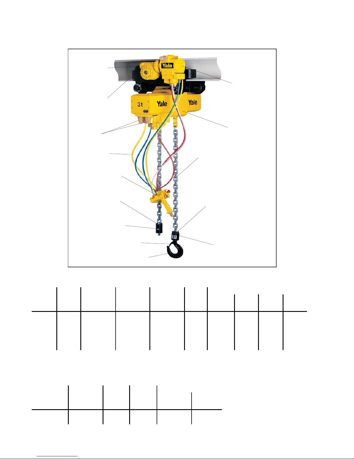
Fig. 1
Trolley
Pendant control
Trolley motor
Air filter
Chain hoist
Buffer
Chain stop
Load chain 11 x 31
Buffer
Lower block
Safety latch
Load hook
Technical Data CPA
Technical Data Motor Trolley
Controls
Air pressure hose
Page 3

3
1. GENERAL INFORMATION
Attention: All users must read these operating instructions care-
fully prior to the initial operation. These instructions are intended
to acquaint the user with the hoist/trolley and enable him to use it
to the full extent of its intended capabilities
The operating instructions contain important information on how
to handle the hoist/trolley in a safe, correct and economic way.
Acting in accordance with these instructions helps to avoid dangers, reduce repair costs and down time and to increase the reliability and lifetime of the hoist/trolley. Anyone involved in doing
any of the following work with the hoist/trolley must read the operating instructions and act accordingly:
operation, including preparation, trouble shooting during operation and cleaning maintenance, inspection, repair
transport
Apart from the operating instructions and the accident prevention
act valid for the respective country and area where the hoist/trolley is used, also the commonly accepted regulations for safe and
professional work must be adhered to.
Every unit leaving the factory is furnished with a test certificate
showing the serial number of the hoist.
The continuous sound level at the place of work is equal to 75 dB.
The measurement was taken at a distance of 2.2 m from the hoist
in 1 position in accordance with DIN 45635 precision class 2.
2 OPERATING INSTRUCTIONS
2.1 CORRECT OPERATION
Capacity / max. safe working load
The Yale pneumatic chain hoist CPA is designed to lift and lower
loads up to the rated capacity. The lifting capacity indicated on the
hoist is the maximum safe working load which must not be exceeded.
Danger zones:
Do not lift or transport loads while
personnel are in the danger zone.
Do not allow personnel to pass
under a suspended load.
After lifting or tensioning, a load
must not be left unattended for a
longer period of time.
Start moving the load only after it
has been attached correctly and
all personnel are clear of the
danger zone.
Fig. 2
Attaching the hoist
The operator must ensure that the hoist is attached in a manner
that does not expose himself or other personnel to danger by the
hoist, chain(s) or the load.
INDEX PAGE
1. General information 3
2. Operating instructions 3
2.1 Correct operation 3
Capacity / max. safe working load 3
Danger zones 3
Attaching the hoist 3
Temperature range 4
Regulations 4
Maintenance/repair 4
2.2 Incorrect operation 4
2.3 Commissioning 4
inspection before initial operation 4
Inspection before starting work 4
Inspection of load chain 4
Inspection of chain stop 4
Inspection of chain reeving 4
Inspection of suspension and load hooks 5
Attaching the load 5
Inspecting the traverse (for trolleys) 5
Check adjustment of trolley width 5
3. Assembly 5
3.1 Inspection before assembly 5
3.2 Pneumatic chain hoist with hook suspension
(Standard design) 5
3.3 Pneumatic chain hoist with trolley 5
Fitting the trolley 6
3.4 Air pressure connections 6
4. Functional check after assembly 6
5. Operation 7
Installation, service, operation 7
Traversing the trolley 7
Attaching the load 7
Lifting the load 7
Emergency stop 7
6. Service 8
6.1 Daily checks 8
6.2 Regular inspections, service, testing 8
6.3 Load chain 9
Lubricating the load chain 9
Inspecting the load chain for wear 9
Replace the load chain 9
Single fall design 9
Two-fall design 9
6.4 Load and suspension hooks 10
6.5 Trolleys 10
6.6 Pneumatic hoists in general 10
6.7 Overload protection device 10
6.8 Gearbox 10
Checkoil level
Oil change 10
Disassemble and reassemble the gearbox 11
6.9 Air motor 12
Motor 12
Disassemble and reassemble the motor 12-13
Page 4
4
Temperature range:
The hoists can be operated in ambient temperatures between
-10 OC and +50 OC.
Consult the manufacturer in case of extreme working conditions.
Note: At ambient temperatures below 0 OC check the brake is not
frozen.
Regulations
The accident prevention act and/or safety regulations of the respective country for using manual hoists must be strictly adhered
to. In Germany these are VGB8, VBG9, VBG9a, ZHI/25, ZHI/27.
Maintenance / Repair:
In order to ensure correct operation not only the operating instructions, but also the conditions for inspection and maintenance must
be complied with. If defects are found stop using the hoist immediately.
Attention: Before starting work on pneumatic components switch
OFF the main air supply and secure it against unintentionally being switched back on.
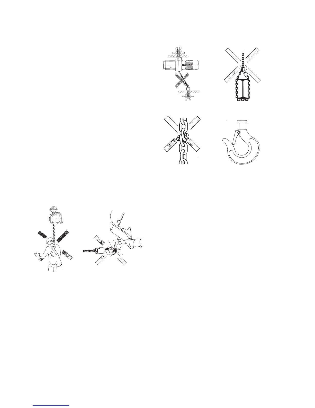
2.2 INCORRECT OPERATION
• Do not exceed the rated capacity of the hoist.
• Do not use the hoist for the transportation of people (fig. 3)
• Welding on hook and load chain is strictly forbidden. The load
chain must never be used as a ground connection during welding
(fig. 4).
Avoid side pull, i. e. side load on either housing or bottom block
(fig. 5).
• Lift/ pull/ tension only when load chain forms a straight line between both hooks.
• The load chain must not be used for lashing purposes (sling
chain) (fig. 6).
• Do not knot or shorten the load chain by using bolts / screws /
screwdrivers or other devices (fig. 7). Do not repair load chains
installed in the hoist.
• Do not remove the safety latch from the suspension or load
hooks (fig. 8).
• Do not use the chain stop as an operational limit device
(see fig. 1 - chain stop)
• Do not throw the hoist down. Always place it properly on the
ground.
2.3 COMMISSIONING
Inspection before initial operation
Each hoist must be inspected prior to initial operation by a
competent person and any faults rectified. The inspection is
visual and functional and shall establish that the hoist is safe
and has not been damaged by incorrect transport or storage.
Inspections should be made by a representative of the manufacturer or the supplier although the company can assign its
own suitably trained personnel.
Inspections are instigated by the user.
Inspection before starting work:
Before starting work inspect the hoist, chain(s) and all load
bearing constructions every time for visual defects. Furthermore test the brake and that the load and hoist are correctly
attached by carrying out a short work cycle of lifting/pulling or
tensioning and releasing. The selection and calculation of a
suitable suspension point for the hoist is the responsibility of
the user.
Inspection of load chain:
Inspect the load chain for sufficient lubrication and visually
check for external defects, deformations, superficial cracks,
wear or signs of corrosion.
Inspection of chain stop:
The chain stop must be connected to the free (idle) chain
strand ( see fig. 1 - chain stop ).
Inspection of chain reeving:
All units equipped with two or more chain strands should be
inspected prior to initial operation for twisted or kinked chains.
The chains of two strand hoists may be twisted if the bottom
block was rolled over (see fig. 9).
Inspection of suspension and load hooks
Inspect suspension and load hooks for deformations,
damage, cracks, wear or signs of corrosion.
Fig. 4
Fig. 3
Fig. 5 Fig. 6
Fig. 8Fig. 7
Page 5

5
3.3 PNEUMATIC CHAIN HOIST WITH TROLLEY
The trolleys are supplied pre-assembled for beam widths A or
B (see table 1). This is shown on the nameplate. Before installation ensure that the trolley width is correct for the intended
carrying beam.
B
b
No. Description
1 Traverse
2 Nut
3 Washer
4 Centre traverse
Beam width Flange width
[mm]
Flange
thickness
[mm]
from to max.
A
98 180 27
B
180 300 27
Roll pins
bAA
B
Attaching the load
The load must always be seated in the saddle of the hook.
Never attach the load to the tip of the load hook. This
also applies to the suspension hook (fig. 10).
Inspecting the traverse (for trolleys)
Inspect the traverse for correct assembly and visually
check for external defects, deformations, superficial
cracks, wear or signs of corrosion. In particular check
that the roll pins in the centre traverse have bee fitted
correctly (fig. 12)
Check adjustment of trolley width
On chain hoists without suspension hook (CPA-VTP/G/
E) check that the clearance between the trolley wheel
flange and the beam outer edge is equal on both sides
and within the tolerances given (see page 6). Enlarging
the clearances, e.g. to enable the trolley to negotiate
tighter curves, is forbidden.
.
3 ASSEMBLY
3.1 Inspection before assembly
Check for transport damage
Check for completeness
Check that the lifting capacity of hoist and load hook
match
3.2 Pneumatic chain hoist with hook suspension
(Standard design)
The standard Yale pneumatic chain hoist is fitted with a
suspension hook.
The suspension hook is connected to the hoist with two
suspension pins. Independent of how the hoist is reeved
it must always hang vertically under the suspension hook.
In single-fall operation the suspension hook is to be installed centred on the marking 1/1, for dual-fall operation centred on the marking 2/1 (see fig. 11).
Attention: Secure the two suspension pins with the locking plate after assembly.
The selection and calculation of a suitable suspension
point is the responsibility of the user and must be adequate to
support the hoist while it is being operated at its maximal lifting capacity.
Fig. 12
1
2
3
4
5
6
7
8
5
3
2
8
Fig. 10
Fig. 9
2/1
1/1
Fig. 11
Fitting the trolley (see fig. 12)
1.) Unscrew the locking nuts (pos. 8) and securing nuts
(pos. 2) from the traverses (pos. 1) and remove the side plates
(pos. 6).
5 Round nut
6 Sideplate
7 Roller
8 Locking nut
Page 6

6
2.) Measure the flange width ”b” of the beam.
3.) Adjust the measurement “B” between the shoulders of the
round nuts (pos. 5) on the threaded traverses (pos. 1).
Ensure that the 4 bores in the round nuts face towards the
outside. Adjust the measurement “B” to equal the measurement “b” plus 4 mm. The measurement “A” must be 2 mm on
each side and the suspension traverse must be centred between the shoulders of the round nuts.
4.) Replace one side plate (pos. 6).
Replace one side plate ensuring that the roll pins in the side
plates engage into the bores in the round nuts. To achieve this
it may be necessary to rotate the round nuts slightly.
5.) Replace the washers (pos. 3) and tighten the securing nuts
(pos. 2). Screw on the locknuts (pos. 8) fingertight and tighten
a further 1/4 to 1/2 turn.
Attention: The locknuts must always be fitted.
6.) Loosely replace second side plate (pos. 6) on the traverse
(pos. 1):
The washers (pos. 3), security nuts (pos. 2) and locknuts (pos.
8) can be fitted loosely.
7.) Raise the complete pre-assembled trolley to the carrying
beam.
8.) Engage the second side plate ensuring that the roll pins in
the sideplate engage into the bores in the round nuts To achieve
this it may be necessary to rotate the round nuts slightly.
9.) Tighten the security nuts (pos. 2) on the second sideplate.
Tighten the locknuts (pos. 8) fingertight and then a further 1/4
to 1/2 turn.
Attention: The locknuts must always be fitted.
10.) By traversing the trolley check following:
That a clearance of 2 mm on each side between the trolley wheel flanges and beam edge is maintained.
The centre traverse is centred below the beam.
That all 4 locknuts are fitted and secured.
11.) Model CPA-VTG only
To fit the handchain, position the slot on the outer edge of the
hand chain wheel below the chain guide. Place one link of the
hand chain vertically into the slot and turn the hand wheel until
the link has passed the chain guides on both sides.
Attention: Do not twist the hand chain when fitting.
Pulling the hand chain moves geared trolleys
3.4 AIR PRESSURE CONNECTIONS
Attention
The brake opening pressure for the disc brake is: min.
2.6 bar. The ”hold open” pressure of 3 bar must be maintained, to ensure that the brake lining does not constantly
slip on the pressure plate.
The operating pressure is 4 - 6 bar.
The compressed air must be clean and enriched with oil to
guarantee adequate lubrication. We, therefore recommend the
use of an oiler that works on the ram-air principle with an adjustable jet. 1 cm
3
of oil amounts to 25 – 30 drops, 2 – 5 drops
are required for every m3 of air used under normal conditions
(see following table).
In any case a lubricator unit comprising of a filter and an oiler
with a pressure regulator in-between (regulator independent
of supply pressure, adjustable and with pressure gauge). When
choosing a unit consider the rate of flow and ensure it is not
fitted more than 5 m away from the hoist.
The lubricant can be replenished in service without disconnecting the air supply.
For the oiler we recommend a resin and acid free lubricating
oil (SAE 5W – SAE 10W), as thicker oils tend to clog the vanes
and reduce the performance of the motor.
The air hose should have a diameter of at least 19 mm. The
connection is R1”.
The connections on the control pendant must not be exchanged.
Page 7

7
Traversing the trolley
Hand trolleys: Pull on the load chain.
Attention: never pull on the air hoses
Geared trolleys: By operating the hand chain
Motor trolleys: By operating the "left" button or "right" button
on the LH side of the pendant control.
Consider the braking distance of the trolley. Do not use the
beam end stops as operational limit devices.
Attaching the load
Attach the load to the hoist using only approved and certified
slings / lifting gear. The load must always be seated in the
saddle of the hook. Never attach the load to the tip of the
hook. Never remove the safety latch from suspension or load
hooks.
Lifting the load
The load is lifting by depressing the "up" button, it is lowered
by depressing the "down" button on the RH side of the pendant control. Do not use the chain stop as an operational limit
device (see fig. 1).
Emergency stop
All movement can be immediately halted by depressing the
red, mushroom shaped button on the pendent control.
Attention: The hoist is still filled with air. To release the
emergency stop, pull the button out again.
4. FUNCTIONAL CHECK AFTER ASSEMBLY
Prior to operating the hoist, grease the trolley pinions (manual
and motor trolleys) and lubricate the load chain when it is not
under load (see page 8).
Before the hoist is put into regular service, following inspections must be made:
• Are all screwed connections on the hoist and trolley tight and
are all locking devices in place and secure?
• Are the end stops on the trolley runway in place and secure?
• Is the hoist correctly reeved?
• Is the chain stop correctly fitted to the loose end of the load
chain (see fig. 1).
• All units equipped with two or more chain strands should be
inspected before initial operation for twisted or kinked chains.
The chains of two fall hoists may become twisted if the bottom
block is rolled over.
• Perform an operating cycle without load. The chain should
move in a steady, smooth way. Check the function of the overload device (max. 5 sec.) by raising the bottom block against
the hoist body.
• Check the brake function when lifting and lowering. The braking distance must not be more than 50 mm.
• Traverse the trolley the complete length of the trolley runway
ensuring that the 2 - 4 mm clearance between the trolley wheel
flange and the beam edge is maintained at all times. Check
that the beam end stops are positioned correctly and secure.
5. OPERATION
In addition to the recommendations in section 1, following rules
must be strictly maintained to ensure the safe operation of the
hoist
Installation, Service, Operation
Users delegated to install, service or independently operate
the hoist must have had suitable training and be competent.
Users are to be specifically nominated by the company and
must be familiar with all relevant safety regulations.
Operating pressure (flow pressure) P 4 5 6 bar
Motor rating P 2 2,75 3,2 kW
RPM (under load) n
bel
2500 2800 3200 1/min
RPM (unloaded) n
leer
4600 5200 5700 1/min
Air consumption at P
Nenn
V 2,9 3,9 4,7 m3/min
Page 8

8
Initial inspection Interval inspection
Inspections and service
work
when
commissioning
after
50 service
hours
after
200 service
hours
daily
after
200 service
hours
annual
Compressed air
components
compressed air supply
•
•
Press-button control Strain
relief
•
•
•
Lubricate load chain
• • •
•
Check for wear in chain
drive
• •
•
Function of slip clutch
•
•
Function of brake
•
•
Chain bolts for cracks
•
•
Check suspension and
load hooks for cracks and
deformation
•
•
Screwed connections for
tightness
•
•
Check trolley for cracks
and deformation
•
•
Oil level in gearbox
•
•
•
Oil change, gearbox
•
•
Check hoist motor and
gearbox
•
Check trolley motor and
gearbox
•
Grease drive transmission
•
Grease lower block
•
•
•
6. SERVICE
Service and inspections may only be carried out by a competent person.
The inspection must determine that all safety devices are
present and fully operational and cover the condition of the
hoist, lifting gear, accessories and supporting constructions.
The service intervals inspections noted are for normal working conditions. Adverse working conditions e.g., heat or chemical environments can dictate shorter periods.
Yale pneumatic hoists conform to the machinery group 1AM
resp. 1Bm in accordance with FEM 9.511. This results in a
theoretical service-lifetime of 800 resp. 400 operating hours
under full load. This is equivalent to 10 years under normal
operating conditions. After this period the hoist requires a general overhaul. Further information is contained in VBG 9 resp.
FEM 9.755.
6.1 DAILY CHECKS
1.) Visually check the pendant control unit and air hoses for
damage.
2.) Check that the brake functions correctly.
3.) Check that the overload safety device functions correctly.
4.) Chain hoists with trolley:
– Check that the trolley runway is free from obstructions.
– Check that the end stops on the trolley runway are fitted
and secured.
6.2 REGULAR INSPECTIONS, SERVICE, TESTING
According to national and international safety regulations hoisting equipment must be inspected annually by a competent
person. Adverse working conditions e.g., heat or chemical
environments can dictate shorter periods.
The commissioning and inspection details can be noted in the
enclosed inspection sheet.
Repairs may only be carried out by specialist workshops that
use original Yale spare parts.
Attention: Disconnect the air supply before performing test
unless air is required for a particular test.
Page 9
9
6.3 LOAD CHAIN
The Yale load chain is quality class 8 chain with the measurements 11 x 13. Yale electric hoists are specially designed
to use this type of chain. For this reason only chains that
have been approved by the manufacturer may be used in
these hoists.
Lubricating the load chain
The load chain is to be lubricated before initial operation
and every 3 months but at the latest after 200 operating hours.
Adverse working conditions, e.g. excessive dust or continued heavy duty can dictate shorter periods between lubrication.
Before the chain is lubricated it must be cleaned. Flamecleaning is forbidden. Use only cleansing methods and
agents that do not corrode the chain material. Avoid cleansing methods that can lead to hydrogen brittleness, e.g. spraying or dipping chain in caustic solvents. Also avoid surface
treatments that can hide cracks and flaws or other surface
damage.
The chain must be lubricated in a no-load condition so that
lubricant can enter between the links, e.g. by dipping in oil.
The whole chain must be lubricated.
Motor oil of the viscosity class 100, e.g. Shell Tonna T68 can
be used to lubricate the chain. For very dusty applications
use a dry lubricant.
Inspecting the load chain for wear
Load chains must be inspected every three months or at the
latest after 200 operating hours (see VBG8 § 27 or local
specifications).
Visually inspect the chain over its full length for deformation,
cracks, flaws, elongation, wear or corrosive pitting.
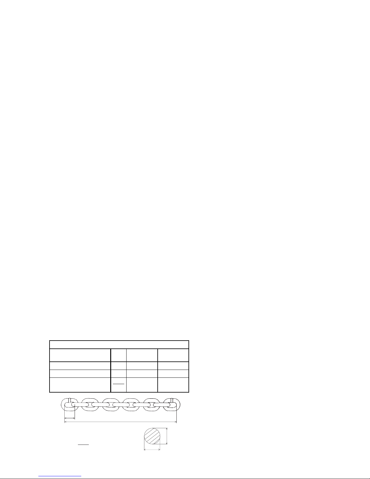
Link chains must be replaced when the nominal thickness
“d” on any part of the chain has been reduced by more than
10% (see fig. 4) or when the partition “t” is elongated by
more than 2% or over 11 partitions (11 x t) by 2%. Nominal
dimensions and wear limits are shown in following table.
Chains that do not fulfil all requirements must be replaced
immediately.
Replace the load chain
Single-fall design
1.) Disassemble lower block
Remove the circlip with suitable pliers. Raise the swivel
tube in the direction of the chain and tap out the chain pin
with a drift.
Attention: Do not damage the chain pin bore.
2.) Remove the chain stop
Remove the 2 screws and remove the chain stop. The chain
is now free.
3.) Fitting the new chain
Cut the second to last link open on the loose end of the
load chain to form a “C”. Remove the last link and connect
the new chain. The new chain must be fitted so that the
welds on the standing links face towards the chain guide
and away from the chain wheel. Operate the hoist in the
“lift” direction to feed the new chain through the hoist.
4.) Fitting lower block and chain stop
Slide the end buffers over the chain ends and refit lower
block and chain stop. The chain stop must be fitted so that
at least 1 link remains free (see fig. 1).
5.) Before initial operation lubricate the unloaded chain and
test all hoist functions under a no-load condition
Two-fall design.
1.) Remove the chain anchor pin
The chain anchor pin is situated on the underside of the
hoist body. With an Allen key remove the grub screw that
serves as the locking device. Tap out the chain anchor pin
from the other side with a drift.
Attention: Do not damage anchor pin or bore.
2.) Pull the load chain through the lower block and remove
the chain stop.
3.) Fitting the new chain
Cut the second to last link open on the loose end of the
load chain to form a “C”. Remove the last link and connect
the new chain. The new chain must be fitted so that the
welds on the standing links face towards the chain guide
and away from the chain wheel. Operate the hoist in the
“lower” direction to feed the new chain through the hoist.
4.) Replace chain stop
Slide the buffer pad over the loose end of the load chain
and refit chain stop ensuring that at least one link remains
free (see fig. 1).
5.) Fitting the chain anchor pin
Inspect the chain anchor pin for flaws, cracks or burrs.
Thread the load chain, ensuring it is not twisted, through
the lower block. Enter the last link of the load chain into the
slot in the underside of the hoist body and enter the anchor
pin through the side bore. Move the last link back and forth
while entering the anchor pin to ensure that it is not trapped
and damaged by the anchor pin. Secure the chain anchor
pin with the grub screw.
6.) Assemble the lower block
Check the chain wheel for damage. Grease the needle bearings in the lower block halves. Place the load hook and the
buffer in the slots provided in one lower block half. Wrap the
load chain around the chain wheel ensuring that the chain is
not twisted and that the welds on the standing links face
away from the chain wheel. Engage the chain wheel, with
load chain, into the pre-assembled lower block half. Ensuring that the buffer pad is situated correctly in its groove replace the second lower block half and secure with the screws.
d1 + d
2
2
<
=
d = nominal thickness of chain
d1, d2 = Actual value
dm = 0,9 d
t
11 x t
d
1
d
2
Link chain 11 x 31 min. quality class 8
Inspection Dim.
Nominal value
[mm]
Limit value
[mm]
Elongation over 11 partitions 11 • t 341 347
Elongation over 1 partition t 31 32
Average link thickness
d
1+d2
2
11,3 10,2
Page 10
10
7.) Functional test
All units with two or more chain strands must be inspected
before initial operation for twisted or kinked chains. Chain
strands may become twisted if the lower block is rolled over.
If a strand is twisted disconnect it from the hoist and rethread it correctly. In some cases it may be necessary to
remove the last link
8.) Before initial operation lubricate the unloaded chain and
test all hoist functions under a no-load condition.
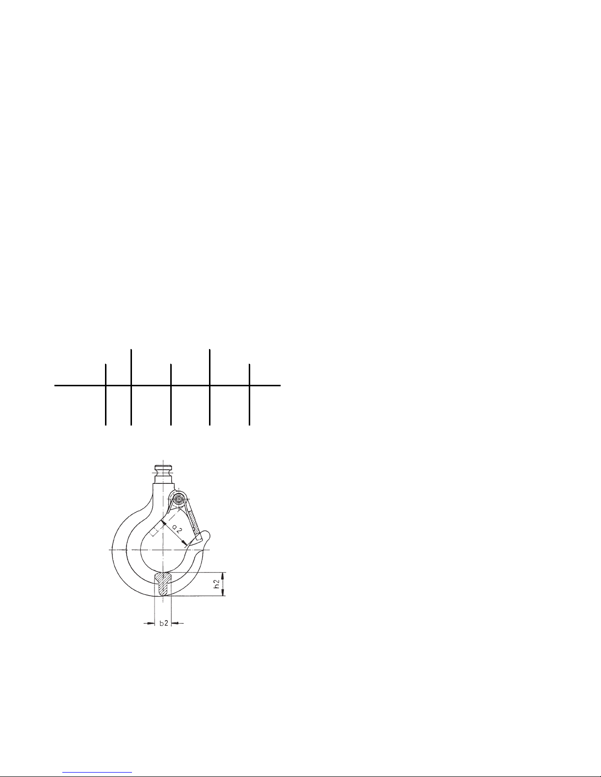
6.4 LOAD AND SUSPENSION HOOKS
Inspect the hooks for deformation, damage, surface cracks,
wear and signs of corrosion as required but at least annu-
ally. Adverse working conditions may dictate much shorter
periods. Hooks that do not fulfil all requirements must be
replaced immediately. Welding on hooks to compensate for
wear or damage is not permissible. Hooks must be replaced
when the mouth of the hook has opened more than 10%
(fig. 14) or the nominal value of other dimensions has decreased by 5% due to wear. Nominal dimensions and wear
limits are shown in the following table. Discard all hooks
that do not fulfil all the requirements of the following table.
6.5 TROLLEYS
In particular check following parts:
• Sideplates:
For cracks or deformation in particular around the areas of
screwed connections.
• Trolley wheels:
Visually check for cracks. Wear on trolley wheel flanges.
Grease the transmission.
• Traverses:
In particular around threaded areas for cracks.
• Fasteners:
Check nuts, screws and locking devices for tightness.
6.6 PNEUMATIC HOISTS IN GENERAL
In particular check following parts:
• Threaded connections in general
Check all nuts, screws and locking devices for tightness.
• Chain bin
Ensure the bin is secure. Check for tears or wear
• Suspension bolts
(Connection between hoist and suspension hook resp. trolley)
Check for cracks or wear. Ensure all safety devices are in
place and secure.
6.7 OVERLOAD PROTECTION DEVICE
The overload protection device is factory set to 110%
+/- 10% of the rated lifting capacity and can be checked by
lifting a suitable load. If the device slips at the rated capacity load it can be adjusted as follows (see fig. 19):
Remove the screws (52) that retain the gearbox cover (51).
Loosen the set screw (47) that presses the steel ball (46)
onto the housing. Turn the adjuster (42) clockwise to increase the tension. Re-check the adjustment with a suitable load. Secure the set screw (47) with a suitable locking
agent, e.g. loctite 243. Replace the gearbox cover (51) and
secure with screws (52).
6.8 GEARBOX
The gearbox is practically service-free. Service is therefore reduced to checking the oil level and changing the oil.
Check oil level
Ensure that the hoist is horizontal and has been stationary
for at least 30 minutes (this allows the oil to drain to the
lower part of the gearbox). Remove the fill-plug. Oil should
be up to the lower edge of the fill hole.
Oil change
The oil (around 0,3 l) is to be changed every 5 years or at
the latest after 400 operating hours.
Remove the screws (52) that retain the gearbox cover (51).
Remove the fill-plug (44). Tip the hoist vertical so that the
oil can drain from the fill hole into a suitable container (can
take up to 30 min.). Replenish the gearbox oil. We recommend a mineral oil viscosity class ISO-VG 460 e.g. FINA
GIRAN L 460. Finally re-adjust the overload protection device and secure the screw with a locking-agent, e.g. Loctite
241.
CPA 20 / 30 CPA 40 / 50 / 60
Inspection Dim. Nominal
[mm]
Limit
[mm]
Nominal
[mm
Limit
[mm]
Hook saddle b
2
24 22,8 29,5 28
Hook saddle h
2
35 33,2 44,5 42,3
Mouth
dimension
a
2
43 47,3 54 59,4
Fig. 14
Page 11

11
Disassemble and reassemble the gearbox
Attention: The gearbox has oil lubrication
Disassemble (see fig. 19)
1. Remove the coupling (50) from the shaft (35). Remove
the screws (52) and remove the gearbox cover (51).
2 Remove the filler plug (44) and gasket (45)
3. Stand the gearbox upright and drain the oil into a suitable
container.
4. Loosen the set screw (47) and remove the steel ball
(46). Unscrew the adjuster (42).
5. Remove the cup spring (41).
6. Remove the locking screw (38) and remove the
retention pin (39).
7. Remove the circlip (37), bearing plate (33) and bearing
( 36). Remove circlip (34) and press the bearing (36)
out of the bearing plate (33). Remove the circlip (37)
from the gearbox shaft (35).
8. Remove brake disks (28) and gear ring (29).
9. Remove planet gears (32), needle bearing (31), thrust
washer ( 30), planetary gear shaft (27) and pinion gear
(26). Remove gearbox shaft ( 35).
10. Remove set screw (17).
11. The remaining parts within the housing (1) can be
removed from the flange side. It is helpful to tap the
edge of the body in an axial direction (flange end) with
a wooden or rubber hammer to loosen the bearing end
plate (15).
12. Remove the planet gears (25), needle bearings (24)
and thrust washers (23) from the planet carrier (22).
13. Remove planet carrier ( 22) and pinion (21) from the
plant carrier (3).
14. Remove bearing (20) and bearing plate (15) from the
planet carrier (3).
15. Remove the circlip (11) from the planet carrier (3) and
press out the planet wheel shaft ( 10).
16. Remove planet wheels (7), needle bearings (8), thrust
washers (6) and spacer ring (9).
17. Remove bearing (5) and seal (4).
Clean and inspect all parts. Replace all worn or damaged
parts and the gearbox is ready for reassemble.
Expendable parts are:
thrust washers (6, 23, 30), needle bearings (8, 24,
31), O-Rings and seals (4, 16, 18, 43) and the seal (45)
Reassemble
Reassemble the gearbox in the reverse order according to
the sectional drawing (see fig. 19).
Take great care to fit the planet gears (7) with needle
bearings (8) of the same sort, thrust washers (6) and spacer
washers (9) properly into the planet carrier (3).
The brake disks either side of the gear ring (28) must be
steeped in oil (soak for one hour in oil) before they are fitted.
The exact adjustment of the overload device is first possible
when the unit is completely reassembled. A preliminary
adjustment is made by compressing the cup springs (41)
with the adjuster (42). Once the final adjustment has been
made secure the adjustment with the set screw (47) and
steel ball (46).
Fill the gearbox with around 0,3l gearbox oil (CLP 460
according to DIN 51547).
Replace plug (44) and gasket (45).
Page 12

12
6.9 AIR MOTOR
Motor
The length of the motor's working life is influenced greatly
by the factors:
a) cleanliness of the air supply
b) lubrication conditions and service
to a) if water and rust can build up inside the air supply system
dirt and water traps must be fitted.
to b) Always use resin and acid free oil (SAE 5W - SAE
10W). Thicker oils clog the vanes and reduce the speed and
power of the hoist. An optimal lubrication extends the working
life of the motor considerably. We highly recommend that
service and oiler units are fitted.
Adjust the oiler so that for every m
3
/min. of air consumed
around 2 - 5 drops of oil are sprayed.
Expendable parts - in particular the vanes - should be
replaced on time. They are worn when their height is less
than 25 mm. We also recommend that the O-Rings (18) that
serve as start-up helps are also be replaced.
One of the main expendable parts are the brake linings (44).
The lining thickness should be controlled at regular intervals
as the wear affects the efficiency of the brake to hold.
The brake disk must be replaced when it's total thickness
becomes less than 7.5 mm or if the brake lining on any side
is less than 2 mm thick.
Disassemble and reassemble the motor
Disassemble - vanes and brake disk
1.) Change vanes (see fig. 20)
Remove the screws (27), end plate (25) and cup spring (24).
With the help of a puller remove the seal plate with bearing
(20) from the rotor. Remove the spacer (23). Remove the
vanes (17) from the rotor slots.
If a puller is not available the complete internal parts can be
removed to be further disassembled on the workbench.
To remove the sealing plates (5) and (20) it can be helpful to
tap the rotor shaft ends on a wooden surface. The motor
cylinder (9) can now be removed and the vanes can be
extracted from the rotor slots. Before replacing new vanes
clean the rotor slots from oil and resin residues. The new
vanes must move freely in the rotor slots (12).
2.) Renew the brake disc
Remove screws (33) and motor end cover (32). Remove
the screws (55). ATTENTION: the springs (53) are under
tension. Remove the brake housing cover (54) and springs
(53). Withdraw the air brake housing (46) complete with parts
(47 - 52) from the brake housing (40). Note the O-Ring (45).
Remove the brake disc (44) from the rotor shaft and check
the lining thickness.
Before reassemble clean the brake housing (40) pressure
plate (51) from brake dust.
Coat the rotor shaft end (12, spline) and the inner spline of
the brake disk (44) with an antirust paste (e.g. Altemp Q NB
50) to ensure that the brake disc (44) can move freely on the
rotor (12) spline. Repeat this procedure on the pressure plate
spline (51) and the brake housing (40).
3.) Complete disassembly
Once the motor parts have been removed as described in
1.) and the seal plates (5 and 20) have been removed from
the rotor, the motor cylinder (9) and vanes (17) can been
removed, if required, the bearings (6 and 21) can be removed
from the seal plates (5 and 20) by releasing the circlips (7
and 22). Remove the complete control valve from the motor
body (1). Remove the screws (55) and withdraw the brake
assembly (40 - 54) from the body (1). Remove the O-Ring
(29), seal plate (30) and oil seal (31). Normally the silencer
(2) remains in the body (1) and is only removed if defect.
Original
size
Replace
O-Ring
Brake disk
assy.
Original
Original
Replace
Replace
Page 13

13
The brake unit is, in part, disassembled as described in 2.).
After removing the circlip (52) the pressure plate (51) can be
removed from the air brake piston (49) this, in turn, can now
be removed from the air brake housing (46). If the exchange
valve function in the brake housing (40) is defect release the
spacer screws ( 42) and remove the control piston (41).
Reassemble
In the main reassemble is performed in the reverse order to
disassembly.
Pay attention to the motor clearances.
The axial play between the rotor (12) and the seal plates
(5 and 20) should be around 0.04 mm
The broken edges on the spacer rings (8 and 23) must face
in toward the middle of the rotor
Before replacing the vanes (17) clean the rotor slots from oil
and resin residues. The new vanes must move freely in the
rotor slots (12). Grease the bearings (6 and 21).
ATTENTION: If the bearings (6 and 21) have been renewed
the clearances must be readjusted (see drawing above).
Ensure that the bearing inner race is pressed, without play,
against the circlip to set the spacer ring (8 and 23) clearances
(new spacer rings must always be adapted). After fitting the
motor cover (25) the rotor (12) must rotate freely. If the rotor
is hard to rotate or does not rotate at all it can be helpful to
apply light taps with a rubber hammer to the motor housing
(1, to the side or axially) to seat the rotor (12) and remove
tensions. Replace the oil seal (31) and seal plate (30). Take
care not to damage the sealing lips! Position the O-Ring
(29) and replace the brake housing (40) complete with
change valve. Remember to position O-Ring (43).
Apply antirust paste as described above (to rotor splines
(12), brake housing (40) and brake disc (44)). Replace brake
disc and ensure it moves freely. Pre-assemble air brake
piston and (49) and pressure plate (51) into the air brake
housing. Coat all moving faces with antirust paste. Replace
the brake housing assembly (40). Enter the springs (53).
Centre the brake housing cover (54) and secure with screws
(55). Replace motor cover (32) and secure with screws (33).
Replace the air control valve and check all motor functions.
Due to the asymmetric design of the hoist the running noises
and idle speeds for RH and LH rotation differ. The values
quoted in the table on page 7 always refer to the pull/lifting
side. Test the brake open and hold open functions when air
is applied. To prevent a continual slipping of the brake linings
a pressure of at least 2.6 bar must be applied.
Broken edges
Around
Around
Page 14

14
1
2
6
4
7
8
9
11
11
15
20
25
5
7
Fig. 16: Hoist body
3
10
18
22
17
14
16
13
23
29
12
26
14
14
14
Motor siehe
Seite 18-19
Motor see
page 18 - 19
Page 15

15
Yale-part. No.
No. Description Qty. CPA 20-8 CPA 30-6 CPA 40-4 CPA 50-3 CPA 60-3
1-11 S uspension unit assy. 1 0609449 0609449 0609449 0609449 0609449
1 Body half, motor side 1 0608972 0608972 0608972 0608972 0608972
2 Body half, gearbox side 1 0608974 0608974 0608974 0608974 0608974
3 Chain guide 1 0608976 0608976 0608976 0608976 0608976
4 Chain stripper 1 0608978 0608978 0608978 0608978 0608978
5 Load chain sheave 1 0609374 0609374 0609374 0609374 0609374
6 Roll pin 2 9134001 9134001 9134001 9134001 9134001
7 Pin 2 9124169 9124169 9124169 9124169 9124169
8 Pin 2 9124111 9124111 9124111 9124111 9124111
9 Bearing 1 9151106 9151106 9151106 9151106 9151106
10 Screw 1 9102253 9102253 9102253 9102253 9102253
11 Screw 2 9102254 9102254 9102254 9102254 9102254
12 Air motor 1 0850003 0850003 0850003 0850003 0850003
13 Planetary gearbox 1 0609678 0608814 0609678 0608814 0608814
14 Screw 8 9101660 9101660 9101660 9101660 9101660
15 Shaft 2 0609388 0609388 0609388 0609388 0609388
16 Locking plate 1 0609448 0609448 0609448 0609448 0609448
17 Screw 2 9102150 9102150 9102150 9102150 9102150
18 Plug 2 9110007 9110007 9110007 9110007 9110007
20 Plug 1 9192003 9192003 9192003 9192003 9192003
21 Plug 1 9192002 9192002 9192002 9192002 9192002
22-23 Suspension hook assy. 1 0609393 0609393 0609517 0609517
23 Safety latch kit 1 0408671 0408671 0408671 0408671
25 Nameplate 1 0800058 0800058 0800058 0800058 0800058
26 Nail 2 9128004 9128004 9128004 9128004 9128004
27 Capacity plate 1 0600002 0609696 0600001 0609511 0600212
28 Nameplate 2 0609692 0609692 0609692 0609692 0609692
29 Anchor pin 1 --- --- 0608855 0608855 0608855
Page 16

16
1
9
7
4
8
6
3
2
5
15
19
21
24
28
17
25
29
12
13
15
20
18
21
20
11
10
14
26
27
22
23
16
2223
Fig. 17: Lower block
1- fall
2- fall
Yale-Part. No.
Y
No. Desc ription Qty. CPA 20-8 C PA 30-6 No. Description Qty. CPA 40-4
1-8 Lower block assy. 1 0609993 0609909 15-23 Lower block assy. 1 0609994
1-2 Hook assy. 1 0408430 0408430 15 Coupling half 2 0609495
2 Safety latch kit 1 0408671 0408671 16 Load chain sheave 1 0609505
3 Load hook coupling 1 0608851 0608851 17 Buffer 1 0601704
4 Tube 1 0600003 0609908 18 Capacity plate 2 0600001
5
Ball kit (15 pieces. á ∅5)
1 0404767 0404767 19
Nail ∅3 x 4
8 9128004
6 Set screw 1 9114030 9114030 20 Screw 2 9102053
7 Circlip 1 9139020 9139020 21 Nut 2 9115118
8 Anchor pin 1 0608855 0608855 22 Needle bearing 2 9153083
9 Buffer 1 0609734 0609734 23 Shim 2 9121218
10-14 Sw ivel block a ssy. 1 0609995 0609995 24-25 Load hook assy. 1 0408434
10 Swivel block half 2 0608867 0608867 25 Safety latc h kit 1 0408672
11 Screw 1 9102019 9102019 26-28 Hook connector 1 0404850
12 Lock washer 1 9122032 9122032 27
Ball kit (16 pieces. á ∅6)
1 0404799
13 Nut 1 9115014 9115014 28 Set screw 1 9114184
14 Buffer 1 0609734 0609734 29 C hain (for all units)*
* Quote length
Page 17

17
2
3
Yale-Part. No.
No. Description Qty. all units
1 Chain container assy. for 13 m chain 1 06109467
1 Chain container assy. for 21 m chain 1 06109468
2 Screw 1 9102255
3 Nut 1 9115098
1
Fig. 18: Chain container
Page 18

18
Fig. 19: Gearbox
Page 19

19
Yale-Part. No. Yale-Part. No.
No.
Description
Qty.
CPA 20-8
CPA 30-6
CPA 40-4
CPA 50-3
CPA 60-3
No.
Description
Qty.
CPA 20-8
CPA 30-6
CPA 40-4
CPA 50-3
CPA 60-3
Planetary gearbox, ass. 1 00600230 27 Planet carrier assy. 1 00600251
1 Housing 1 00600237 27.1 Washer 1 00600252
2 Ring 1 00600238 27.2 Planet shaft 3 00600253
3 Planet carrier 1 00600239 28 Brake lining 2 00600254
4 Oil seal 1 09172110 29 Annulus 1 00600255
5 Bearing 1 09150043 30 Thrust washer 3 09153043
6 Thrust washer 6 091530 43 31 Needle bearing 3 09153090
7 Planet gear 3 00600240 32 Planet gear 3 00600171
8 Needle bearing 6 09153090 33 Washer 1 00600256
9 Spacer ring 3 00600241 34 Retaining ring 2 09130034
10 Planet shaft 3 00600242 35 Shaft 1 006002 57
11 Retaining ring 1 09129070 36 Bearing 1 09150043
13 Ring 1 00600243 37 Retaining ring 2 09129029
14 Retaining ring 1 09129071 38 Lock screw 1 00600258
15 Ring 1 00600244 39 Pin 1 00600259
16 O-Ring 1 09171352 40 O-Ring 1 09171169
17 Set screw 1 09114134 41 Cup spring 4 09120041
18 Oil seal 1 09172112 42 Adjuster 1 00600260
19 Shim 1 091212 34 43 O-Ring 1 09171170
20 Bearing 1 09151101 44 Plug 1 09110052
21 Sun wheel 1 00600245 45 Gasket 1 09179004
22 Planet carrier assy. 1 00600246 46 Ball 1 09159011
22.1 W asher 1 00600247 47 Set screw 1 09114136
22.2 Planet shaft 3 00600248 48 Shim 1 09121056
23 Thrust washer 3 09153043 50 Cou pling 1 00608879
24 Needle bearing 3 09153090 51 Cover 1 00600262
25 Planet gear 3 00600249 52 Screw 4 09102019
26 Sun wheel 1 00600250
Attention: When ordering spare parts please indicate item number and manufacturing year of the unit.
Page 20

20
Fig. 20: Motor
60
Yale-Part. No Yale-Part. No
No Description Qty.
for all units
Description Q ty.
for all units
Motor assy. 1 00850003 31 Oil seal 1 00800042
1 Housing 1 00800013 32 Cover 1 00800024
2 Silencer assy. 6 00800014 33 Screw 4 09102268
3 O-Ring 12 09171115 40-55 Disc brake assy. 1 00800025
4 Roll pin 1 09134048 40 Brake housing assy. 1 00800026
5 Seal plate 1 00800015 41 Control piston f. brake air 1 00800027
6 Bearing 1 09151119 42 Spacer screw 2 00800043
7 Retaining ring 1 09130001 43 O-Ring 2 09171165
8 Spacer ring 1 00800016 44 Brake disc assy. 1 00800028
9 Motor cylinder asymmetric 1 00800017 45 O-Ring 1 09171165
10 Roll pin 1 09134052 46 Air brake housing 1 00800039
11 Roll pin 1 09134048 47 Quad-Ring 1 00800044
12 Rotor 1 00800018 48 O -Ring 1 09171166
17 Vane 7 00800019 49 Brake air piston 1 00800030
18 O-Ring 7 09171163 50 S eal ring 1 00800045
20 Seal plate 1 00800020 51 Pressure plate 1 00800031
21 Bearing 1 09151119 52 Retaining ring 1 09129024
22 Retaining ring 1 09130001 53 Spring 10 00800046
23 Spacer ring 1 00800016 54 Cover 1 00800032
24 Cup spring 1 00800041 55 Screw 4 09102110
25 Cover 1 00800022 60 Sinter metal silencer 2 00800047
26 Oil seal 1 00800042
27 Screw 6 09102040
29 O-Ring 1 09171164
30 Seal plate 1 00800023
Page 21

21
Yale-Part. No Yale-Part. No
No Description Qty.
for all units
Description Qty.
for all units
Remote control assy. 1 08600003 13 Spring 2 00800053
1 Control valve assy. 1 00800033 14 Adjusting screw 2 00800051
2 Guide bushing 2 00800034 15 Seal washer 2 00800054
3 O-Ring 2 09171167 16 Control piston assy. (lift) 1 00800037
4 Cover 1 00800048 17 Control piston assy. (lower) 1 00800038
5 Switch piston 1 00800035 18 Glyd Ring assy. 2 00800055
6 Pneum. Lip ring 1 00800049 19 Pneum. Lip ring 2 00800056
7 O-Ring 1 09171168 20 Seal 1 00800057
8 Spring 1 00800050 21 Connection plate 1 00800039
9 Adjusting screw 1 00800051 22 Screw 6 09102065
10 Seal washer 1 00800052 23 S eal 1 00800040
11 Bushing 2 00800036 24 Screw 6 09102015
12 O-Ring 2 09171167
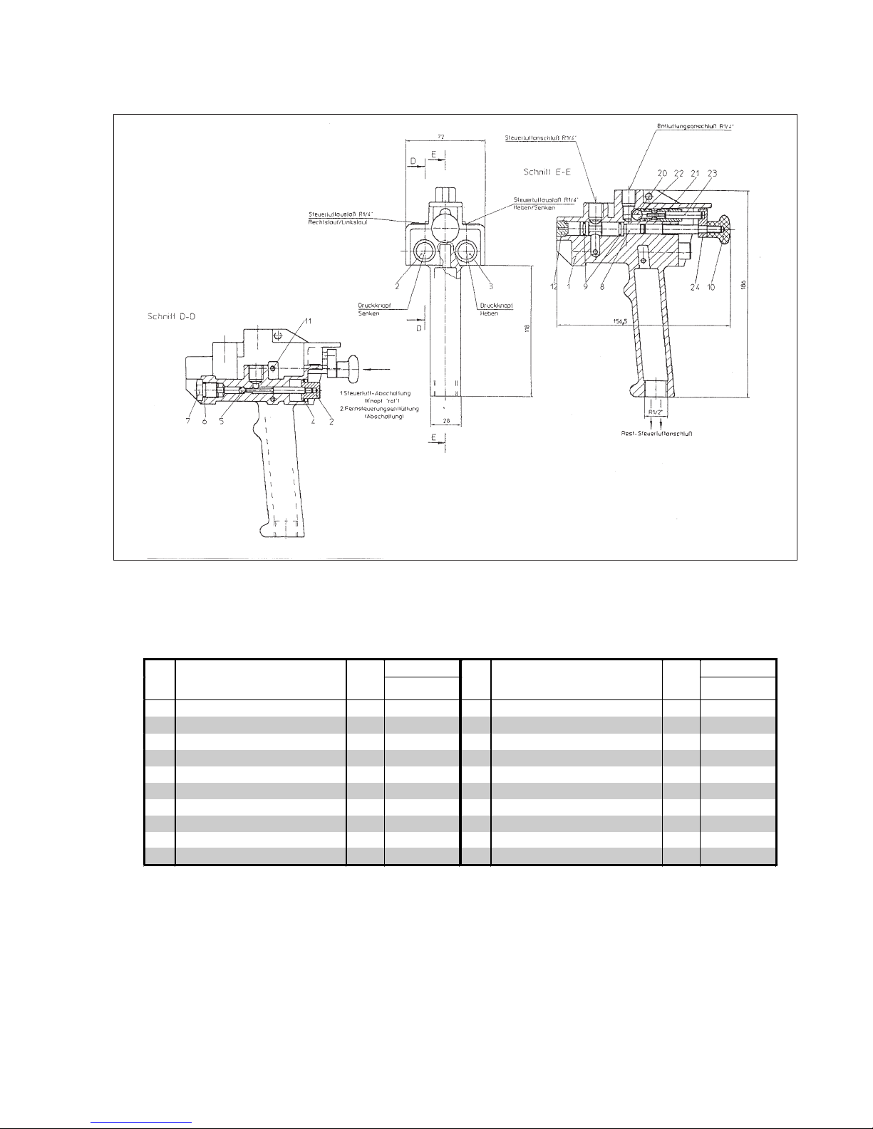
Fig. 22: Remote control
Page 22

22
Fig. 23: Rope control
Yale-Part. No Yale-Part. No
No Description Qty.
for all units
Description Qty
for all units
Rope control unit 1 17 Square ring 1 00800064
1 Housing assy. 1 00800059 18 Control gear 1 00800068
2 Reversing bushing 1 00800060 19 Retaining ring 1 09129025
3 Reversing piston 1 00800061 20 Seal 1 00800069
4 Needle bearing 2 09153096 21 Screw 6 09102175
5 Shaft l 1 00800062 22 Centring ring 2 00800070
6 Key 1 09131025 23 Spring guide 2 00800071
7 Seal bushing 2 00800063 24 Spring 2 00800072
8 Square ring 2 00800064 25 Plug 2 00800073
9 Retaining ring 2 09129025 26 Screw 8 09102061
10 Toggle 1 00800065 27 O-Ring 2 09171171
11 Housing 1 00800066 28 Seal 1 00800074
12 Needle bearing 2 09153096 29 Lockwasher 3 09122031
13 Seal bushing 1 00800063 30 Screw 3 09102040
14 Square ring 1 00800064 31 Screw 3 09102169
15 Shaft II 1 00800067 32 Seal 2 00800075
16 Key 1 09131025
Page 23
23
Yale-Part. No. Yale-Part. No.
No Description Qty.
for all units
Description Qty
for all units
Button control assy. (2 way) 1 08600001 9 O-Ring 2 09171174
1 Button control -housing assy. 1 00800076 10 Button, red 1 00800081
2 Valve pusher 2 1 00800077 11 Spring compressor 1 00800082
3 Valve pusher 1 1 00800078 12 S top screw 1 00800083
4 Retaining ring 2 09130059 20 Ball 1 09159016
5 Ball 2 09159019 21 Valve screw 1 00800084
6 O-Ring 2 09171173 22 O-Ring 1 09171172
7 Plug 2 00800079 23 Valve pin 1 00800085
8 Switch piston 1 00800080 24 Carrier pin 1 00800086
Abb. 24: Button control (2 way)
Page 24

24
Fig. 25: Button control (4 way )
Yale-Part. No. Yale-Part. No.
No Description Qty.
for all units
Description Qty
for all units
Button control assy. (4 way) 1 08600002 9 O-Ri ng 2 09171174
1 Button control-housing assy. 1 00800087 10 Button, red 1 00800081
2 Valve pusher 2 2 00800077 11 Spring presser 1 00800082
3 Valve pusher 1 2 00800078 12 S top screw 1 00800083
4 Retaining ring 4 09130059 20 Ball 1 09159016
5 Ball 4 09159019 21 Valve screw 1 00800084
6 O -Ring 4 09171173 22 O-Ring 1 09171172
7 Plug 4 00800079 23 Valve pin 1 00800085
8 Switch piston 1 00800080 24 Carrier pin 1 00800086
Page 25

25
2
5
8
6
8
6
8
8
6
1
9
5
15
15
13
6
11
9
5
4
4
5
11
10
3
9
7
10
7
12
7
14
Yale-Part. No. Yale-Part. No.
No Description Qty.
for all units
Description Qty.
for all units
1 Sideplate 1 0559163 8 Locknut 4 9115155
2 Sideplate 1 0559167 9 Roller 4 0508210
3 Roll pin 4 9134120 10 Bearing 8 9151079
4 Traverse beam width A 2 0559169 11 Retaining ring 4 9129003
4 beam width B 2 0559170 12 Nameplate 1 0559869
5 Round nut 4 0559168 13 Nail 4 9128004
6 Washer 4 9121213 14 Centre traverse 1 0559353
7 Nut 4 9115156 15 Roll pin 2 9134002
Fig. 26: trolley
9
10
7
10
11
Page 26

26
Yale-Part. No. Yale-Part. No.
No Description Qty.
for all units
Description Qty.
for all units
1 Roller, geared 2 0508214 10 Chain guide 1 0558062
2 Bearing 8 9151079 11 Screw 2 9101014
3 Retaining ring 4 9129003 12 Nut 2 9115148
4 Mounting 1 0508229 13 Drive shaft 1 0710029
5 Guide 1 0710030 14 Roll pin 1 9134052
6 Lockwasher 4 9122016 15 Hand chain sheave 1 0558061
7 Screw 2 9101050 16 Hand chain * 4307654
8 Bushing 1 0102503 17 Connecting link 1 0404733
9 Shim 4 9121205 18 Sideplate 1 0559165
*Quote length
1
10
15
11
6
3
2
12
8
9
7
6
Fig. 27: Geared drive for trolley (other parts see trolley)
17
16
5
18
13
14
4
Page 27

27
Yale-Part. No. Yale-part. No.
No Description Qty.
for all units
Description Qty.
for all units
1 Roller, geared 2 0508214 13 Screw 2 9101014
2 Bearing 8 9151079 14 Lockwasher 2 9122004
3 Retaining ring 4 9129003 15 Key 7 9121215
4 W orm gearbox 1 0719764 16 Pinion 1 0719373
5 Flange 1 0719371 17 Retaining ring 1 9123038
6 Drive shaft 1 0719372 18 Connection 1 9184082
7 Key 1 9131072 19 A ir motor 1 00810001
8 Needle bearing 1 9153077 20 Reducer 1 0719868
9 Retaining ring 1 9129016 21 Bushing 1 0719870
10 Screw 4 9101170 22 Screw 4 9101439
11 Lockwasher 4 9122003 23 S ideplate 1 0559165
12 Roll pin 1 9134080 24 Worm gearbox 1 00710033
Fig. 28: Air motor for trolley (other parts see trolley)
1
2
3
5
6
7
8
9
10
11
12
13
14
15
16
17
19
21
23
Druckluftmotor für
Fahrwerk siehe
Seite 28-29
24
Air motor for trolley
see pages 28 - 29
Page 28

28
Fig. 29: Air motor for trolley
Page 29

29
Yale-Part. No Yale-Part. No
No Description Qty.
for all units
Description Qty
for all units
Air drive 1 00810001 21 Screw 6 09120265
1 Housing 1 00800124 22 Cover 1 00800129
2 Air entry 1 00800125 23 Screw 4 09102248
3 Silencer material 1 00800089 24 Sinter metal silencer 1 00800047
4 Plug 2 00800090 30 Flange housing 1 00800130
5 Seal plate 1 00800091 31 Bearing 1 09151122
6 Bearing 1 09151086 32 Retaining ring 1 09130034
7 Retaining ring 1 09130045 33 Drive shaft 1 00800191
8 Spacer ring 1 00800092 34 Retaining ring 1 09129029
9 Motor cylinder 1 00800126 35 Key and sleeve 1 00719868
10 Roll pin 1 09134077 36 Coupling 1 00800132
11 Roll pin 1 09134042 37 Bearing 1 09150040
12 Rotor 1 00800094 38 W asher 1 00800133
13 Vane 5 00800127 39 Loc kwasher 4 09122031
14 O-Ring 5 09171176 40 Screw 4 09102169
15 Seal plate 1 00800091
16 Bearing 1 09151086
17 Retaining ring 1 09130045
18 Spacer ring 1 00800128
19 Cup spring 1 00800098
20 Cover 1 00800099
Page 30

30
Inspection notes
Inspection before initial operation:
by:
Commissioning date:
Scheduled inspections
Date Result Repair Test
on by*
* Competent person
Page 31

31
EG-DECLARATION OF CONFORMITY
In accordance with EG-Machinery Directive 98/37/EG. Appendix II A.
We,
Yale Industrial Products GmbH
D- 42549 Velbert, Am Lindenkamp 31
hereby declare, that the design, construction and commercialised execution of the below mentioned machine
complies with the essential health and safety requirements of the EC Machinery Directive. The validity of this
declaration will cease in case of any modification or supplement not being agreed with us previously.
Furthermore, validity of this declaration will cease in case that the machine will not be operated correctly and in
accordance to the operating instructions and/or not be inspected regularly.
Machine description:
Pneumatic chain hoist CPA
Mod. CPA20-8, CPA30-6,
Mod. CPA40-4, CPA50-3,
Mod. CPA 60-3
Capacity 2000 - 6000 kg
Machine type:
Pneumatic chain hoist
Serial number:
from manufacturing year 01/00
(serial numbers for the individual capacities/models are registered
in the production book with the remark CE-sign)
Relvant EC Directives:
EG-Machinery Directive (98/37/EWG)
Transposed harmonised
EN 292, part 1 (safety of machines)
Standards in particular:
EN 292, Part 2 (safety of machines)
EN 349 (safety of machines)
EN 818, part 1 (round link chains)
prEN 818, part 4 (round link chains)
Transposed (either complete
FEM 9.671; DIN 5684 (Lastketten)
or in extracts) national
FEM 9.682 (Hubmotoren)
standards and technical
FEM 9.755 (Betriebsdauer)
specifications in particular:
FEM 9.511 (classification)
DIN 15018 (Krane)
DIN 15400 (Lasthaken für Hebezeug)
DIN 15404 (Lasthaken für Hebezeug)
VBG 8 (Winden, Hub- und Zuggeräte)
VBG 9 (Krane)
VBG 9.a (Lastaufnahmemittel)
ZH 1/27 (Prüfung von Kranen)
ZH1/25 (Prüfung von Hubgeräten)
Quality assurance:
DIN/ISO 9001 (Certificate Registration No.: 150)
Date/Manufacturer’s authorised signature:
2001-03-05
Identification of the signee:
Dipl.-Ing. A. Oelmann
Mana
g
er Quality assurance
 Loading...