

Page 1
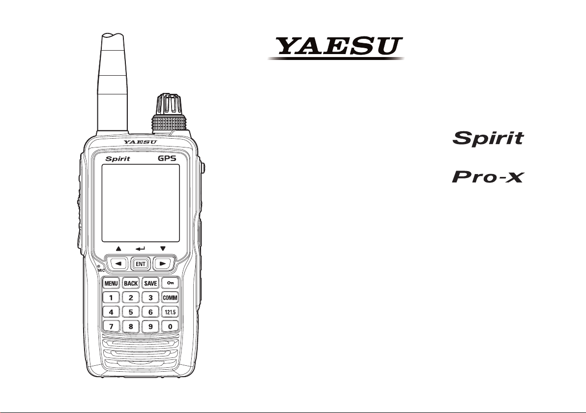
AIR BAND TRANSCEIVER
FTA-750
FTA-550
Operating Manual
Page 2

Contents
Important Notice! .......................................................... 1
Introduction ................................................................... 2
Models, Accessories and Options .............................. 3
Models ............................................................................... 3
Supplied Accessories ......................................................... 3
Available Options .............................................................. 3
Controls & Connectors
LCD Display .................................................................. 8
Before You Begin ........................................................ 12
Battery Installation and Removal .................................... 12
Battery Charging .............................................................. 13
Alkaline Battery Tray Installation ................................... 14
Low Battery Indication .................................................... 14
External DC Power Supply Connection .......................... 15
Antenna Installation ......................................................... 15
Belt Clip Installation ........................................................ 16
Headset Connection ......................................................... 16
Precautions ....................................................................... 17
Basic Operation .......................................................... 18
Reception (COM Band) ................................................... 18
Accessing the 121.5 MHz Emergency Frequency ........... 21
Transmission (COM Band) .............................................. 22
Operation Bands .............................................................. 23
Operation Modes ............................................................. 24
Resetting the Radio .......................................................... 25
Advanced Operation .................................................. 27
Reception of VOR Signals ............................................... 27
Reception of ILS Signals ................................................. 31
Split Operation ................................................................. 33
Reception of Weather Channel Broadcasts ...................... 35
Dual Watch Operation ..................................................... 37
Timer Mode Operation .................................................... 39
TOT Feature ..................................................................... 43
................................................ 4
Saving the Battery during Reception ............................... 43
Using the Headset Microphone ....................................... 44
VOX Operation ................................................................ 44
Side Tone Control ............................................................ 45
Lock Function .................................................................. 46
ANL Feature .................................................................... 48
Memory Operation ...................................................... 49
Recalling the Memories ................................................... 49
Instant Storage ................................................................. 51
Maintenance of the Memory ............................................ 52
Scanning Operation ................................................... 55
Scanning All Channels ..................................................... 55
Scanning the Specied Channels ..................................... 56
GPS Function (FTA-750 Only) ................................... 58
Activating the GPS Unit .................................................. 58
Displaying the Position Information ................................ 59
Memorizing the Position Information ............................. 61
Recording the Position Information ................................ 62
Waypoint Navigation (FTA-750 Only) ........................ 63
Entering the Navigation (NAVI) Mode ........................... 63
Setting the Destination ..................................................... 64
SETUP Mode ............................................................... 67
Basic Operation ............................................................... 67
Maintenance of the Memory ............................................ 68
Setting of the COMM Mode Operation ........................... 69
Setting of the GPS Mode Operation (FTA-750 Only) ..... 72
Setting of the Operation and Conguration of
the Radio .......................................................................... 77
About the Radio ............................................................... 79
Summary of the SETUP Menu ........................................ 80
Specications ............................................................. 82
Troubleshooting for Headset Connection ................ 84
Page 3
Important notIce!
FCC RF Exposure Compliance Requirements for Occupational Use Only:
The
FTA-750/FTA-550
sure limits for Occupational Use/Controlled Exposure Environment. In addition, both radios comply with the following
Standards and Guidelines:
FCC 96-326, Guidelines for Evaluating the Environmental Effects of Radio-Frequency Radiation.
FCC OET Bulletin 65 Edition 97-01 (1997) Supplement C, Evaluating Compliance with FCC Guidelines for Hu-
man Exposure to Radio Frequency Electromagnetic Fields.
ANSI/IEEE C95.1-1992, IEEE Standard for Safety Levels with Respect to Human Exposure to Radio Frequency
Electromagnetic Fields, 3 kHz to 300 GHz.
ANSI/IEEE C95.3-1992, IEEE Recommended Practice for the Measurement of Potentially Hazardous Electromag-
netic Fields - RF and Microwave.
This radio is NOT approved for use by the general population in an uncontrolled environment. This radio is
restricted to occupational use, work related operations only where the radio operator must have the knowledge to control its RF exposure conditions.
When transmitting, hold the radio in a vertical position with its microphone 1 to 2 inches (2.5 to 5 cm) away
from your mouth and keep the antenna at least 1 inch (2.5 cm) away from your head and body.
The radio must be used with a maximum operating duty cycle not exceeding 50%, in typical Push-to-Talk
congurations. DO NOT transmit for more than 50% of total radio use time (50% duty cycle). Transmitting
more than 50% of the time can cause FCC RF exposure compliance requirements to be exceeded.
The radio is transmitting when the “TX” icon is displayed on the upper left corner of the screen of the radio.
You can cause the radio to transmit by pressing the PTT button.
Always use YAESU authorized accessories.
have been tested and comply with the Federal Communications Commission (FCC) RF expo-
NOTICE
There are no user-serviceable points inside this transceiver.
All service jobs must be referred to your Authorized Service Center.
FTA-750/FTA-550 OperATing MAnuAl
1
Page 4

IntroductIon
The YAESU
and receive) capability on the International Aircraft Communication Band (“COM” band: 118 to 136.975 MHz), and
they additionally provide VOR and ILS navigation features on the “NAV” band (108 to 117.975 MHz).
The
FTA-750/FTA-550
a row. The
gurations can be easily reprogrammed in minutes using the optional PC Programming Software and your PC. In addition, the
We recommend that you read this manual in its entirety, so as to understand the many features of the
completely. Keep this manual handy, so you may use it for reference.
550
Note: The VOR, ILS, and GPS navigation features of the
tion only, and are not intended to be a substitute for accurate (primary) VOR or landing service equipment.
You assume full responsibility for the use of the
FTA-750/FTA-550
FTA-750/FTA-550
FTA-750
provides positioning and navigation features realized by the internal GPS unit.
boast a 1.7” x 1.7” (43.2 x 43.2 mm) full dot matrix LCD displaying a plenty of information in
are compact, stylish, solid hand-held transceivers providing communication (transmit
include NOAA weather band monitoring and 200 memory channels. The channel con-
FTA-750/FTA-
FTA-750/FTA-550
FTA-750/FTA-550
are for supplemental aids to naviga-
.
Congratulations!
You now have at your ngertips a valuable communications tool, a YAESU two-way radio! Rugged, reliable
and easy to use, your YAESU radio will keep you in constant touch with your friends and colleagues for years to
come, with negligible maintenance or down-time.
Please take a few minutes to read this manual carefully. The information presented here will allow you to derive
maximum performance from your radio, in case questions arise later on.
We’re glad you joined the YAESU team. YAESU products cover the entire spectrum of radio communications
applications, and our worldwide support network is here to serve you. Let us help you get your message across.
2
FTA-750/FTA-550 OperATing MAnuAl
Page 5

models, accessorIes and optIons
Models
FTA-750L
FTA-550L
FTA-550 AA Battery Version
Rechargeable battery pack not includ-
Supplied Accessories
Lithium-ion Battery Pack (7.4V)
AC Charger
Charger Cradle
Cigarette Lighter DC/DC Converter
Helical Antenna
Belt Clip
Headset Adapter Cable
Alkaline Battery Tray
USB Cable
Ferrite Core
Operating Manual
Warranty Card
Lithium-ion battery pack included
Lithium-ion battery pack included
ed. Requires “AA” batteries for operation.
SBR-12LI
SAD-11
SBH-11
SDD-12
SRA-13A
SHB-11
SCU-15
SBT-12
T9101606
L9190192
*1 These accessories are not supplied with the
FTA-550 AA Battery Version
*2 Antenna gain: 2.15 dBi
Impedance: 50 ohms
.
*1
*1
*1
*2
Available Options
SSM-10A
SEP-10A
YCE01
Availability of accessories may vary. Some accessories
are supplied as standard per local requirements, while
others may be unavailable in some regions. Consult
your YAESU Dealer for details regarding these and any
newly-available options.
Connection of any non-YAESU-approved accessory,
should it cause damage, may void the Limited Warranty
on this apparatus.
Speaker Microphone
Earphone (available only with the
SSM-10A
PC Programming Software
)
FTA-750/FTA-550 OperATing MAnuAl
3
Page 6
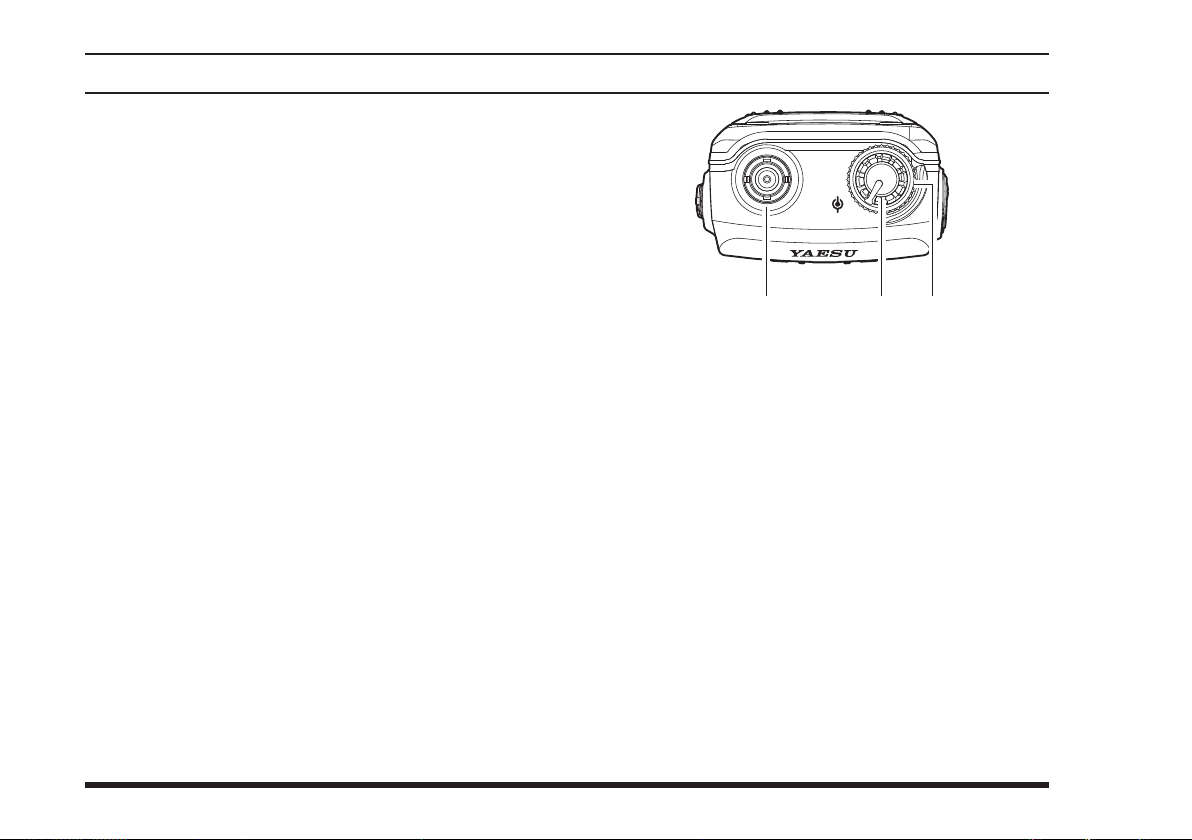
controls & connectors (top panel
Antenna Jack
This BNC connector accepts the supplied flexible
antenna, or an external antenna designed to provide
50 Ω impedance on the Aircraft Communication
Band.
)
VOL
DIAL
VOLUME
Turn this (inner) control clockwise to increase the
volume.
DIAL
This (outer) 20-position detented rotary switch tunes
the operating frequency or selects the memory channels.
(Inner) Knob
Selector (Outer) Knob
4
FTA-750/FTA-550 OperATing MAnuAl
Page 7
controls & connectors (Front panel
)
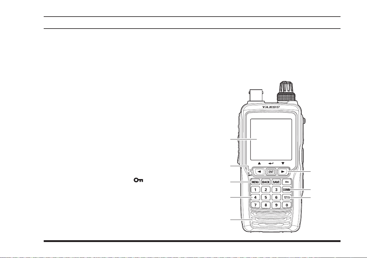
LCD (Liquid Crystal Display)
The display shows selected operating conditions, as
indicated on Pages 8 to 11.
Microphone
Speak into this opening in a normal voice level,
while pressing the
Cursor Keys and
The cursor keys
item displayed on the LCD.
Press the
entered values.
Control Keys
Press the
Press the
previous screen.
Press the
information to the memory.
Press and hold the lock key
lock feature. Controls and keys will be disabled.
Press and hold again to disable the lock feature.
COMM
Press this key to enter the COMM mode instantly.
Numeric Keypad
The keypad is used when setting frequencies.
key to determine the selection or
ENT
MENU
BACK
SAVE
Key
switch, to transmit.
PTT
Key
ENT
[◄]
key to display the
key to return the display to the
key to store the current channel
and
[►]
are used to select an
screen.
MENU
[
]
to enable the
FTA-750/FTA-550 OperATing MAnuAl
121.5
Press and hold this key to access the emergency
frequency (121.5 MHz) instantly.
Loudspeaker
The internal speaker is located in this position.
Key
5
Page 8
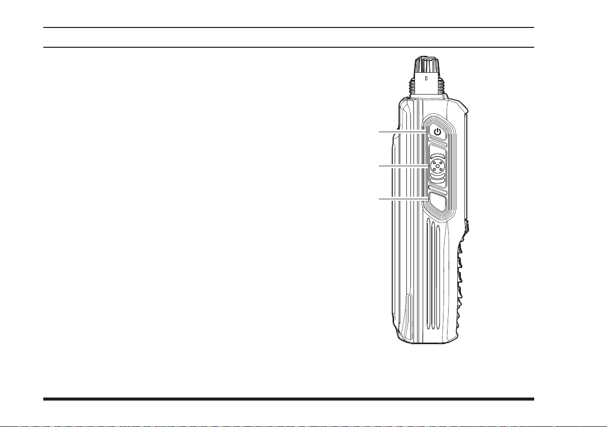
controls & connectors (leFt sIde
)
POWER
Press and hold this button to turn the radio on and
off.
PTT
Press and hold this button to transmit when you are
operating in the COM band. Release this button to
return to the “Receive” mode. See Page 22 for details.
SQL
This button may be pressed to “open” the squelch
manually, allowing you to listen for very weak
signals. Press and hold this button for 2 seconds
to “open” the squelch continuously. Press this button again to resume normal (quiet) monitoring. See
Page 20 for details.
Switch
(Push To Talk) Switch
(Squelch) Switch
PTT
SQL
6
FTA-750/FTA-550 OperATing MAnuAl
Page 9
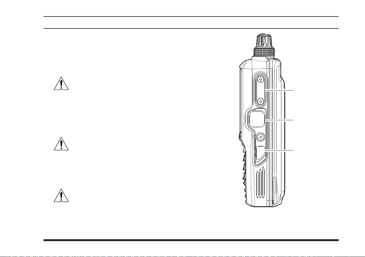
controls & connectors (rIght sIde
PTT
SQL
)
MIC/SP
You may connect the supplied
Adapter Cable or the optional
Microphone to this jack. To use this jack, you must
rst remove the cover from the transceiver body.
DATA
You may connect the optional USB cable to this
jack. To use this jack, you must rst lift the rubber
cover away from the transceiver body.
EXT DC
When an external 9.5- to 10.5-Volt DC power
source is available, you may connect the
Cigarette Lighter DC/DC Converter here.
proved by YAESU to supply DC power.
Jack
SCU-15
SSM-10A
Do not allow the
wet while the cover over the MIC/SP jack is
removed.
FTA-750/FTA-550
Headset
Speaker/
to get
Jack
Do not allow the
wet while the rubber cover is removed.
FTA-750/FTA-550
to get
Jack
1) Do not allow the
get wet while the rubber cover is removed.
2) Do not connect any accessory unap-
FTA-750/FTA-550
SDD-12
to
MIC/SP
DATA
EXT
DC
FTA-750/FTA-550 OperATing MAnuAl
7
Page 10
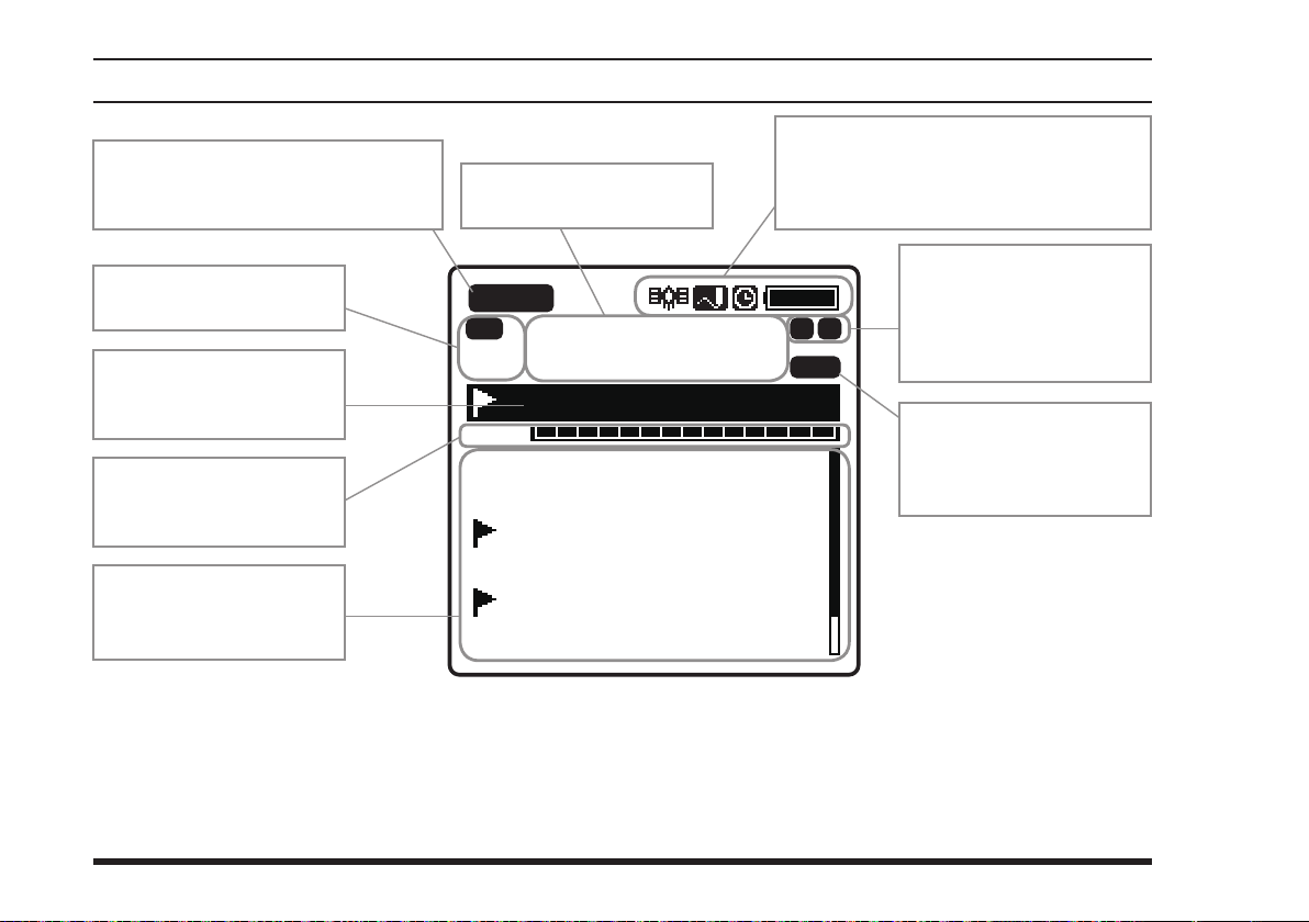
lcd dIsplay (com Band
VOL
BUSY
MEM
VDW ±
FLG
MR
133.800
132.400
134.800 MIAMI
127.600 MIAMI 2
119.150
124.250 North
129.200
Los Angeles
“BUSY” icon appears during
audio reception, or “TX” during
transmission.
This field displays the
operating frequency.
)
This field displays the icons indicating
various statuses of the transceiver, such
as “GPS on”, “Data Logger on”, “Timer
on”, “Battery full”, etc.
This field displays the
operation modes.
This field displays the
tag name of the current
channel.
This field displays the
level of the audio volume
or the squelch.
This field displays the
channels you have
previously used.
8
This field displays the
icons indicating various
statuses of functions,
such as “VOX on”, “Split
on”, etc.
“MEM” icon appears if
the selected channel is
programmed into the Scan
Memory.
FTA-750/FTA-550 OperATing MAnuAl
Page 11
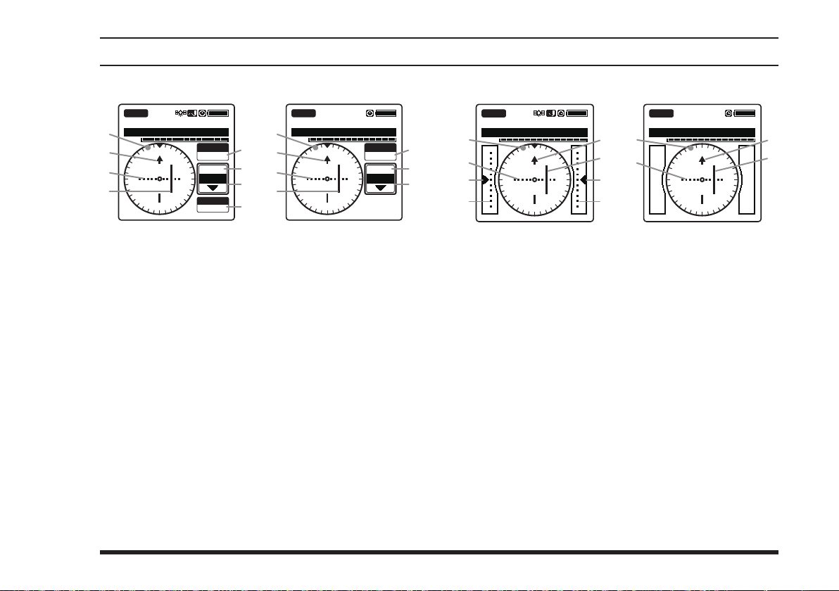
lcd dIsplay (naV Band
)
Vor cdI screen
NAV VOR
113.600
Compass rose
Course indicator (OBS direction)
Deviation marks
Course deviation needle
OBS (omni bearing selector) value
VOR value
TO/FROM indicator
SOG (speed over ground) value according to the
KLAX-VOR
VOL
N
33
30
24
21
S
FTA-750 FTA-550
OBS
000
355
FROM
SOGKT
150
°
°
3
6
EW
12
15
GPS signal
NAV VOR
VOL
33
30
24
21
113.600
KLAX-VOR
N
3
6
EW
12
15
S
OBS
000
355
FROM
Ils cdI screen
NAV
LOC GS
108.500
KLAX-RWY07R
VOL
°
°
N
33
Compass rose
Course (runway) indicator
Deviation marks for localizer
Course deviation needle for localizer
Height deviation indicator for glide slope
Deviation marks for glide slope
3
30
24
FTA-750 FTA-550
6
12
15
21
S
EW
NAV
LOC
108.500
KLAX-RWY07R
VOL
FTA-750/FTA-550 OperATing MAnuAl
9
Page 12
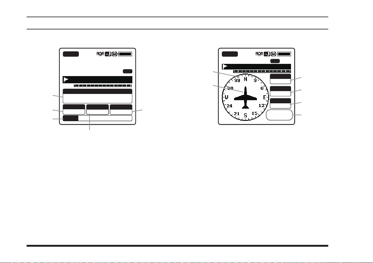
lcd dIsplay (Fta-750 only
)
gps InFormatIon screen
BUSY
MR
FLG
133.800
KLAX-ATIS
VOL
DATE
LAT/LON
23°56.890N
123°56.890W
COG
095
SOGKT
095
°
Oct/25 09:56
0956.8
Latitude and longitude values
COG (course over ground) value
Date obtained from the GPS signal
SOG (speed over ground) value
Altitude value
ALT
AM
MEM
M
gps compass screen
BUSY
MR
FLG
VOL
133.800
KLAX-ATIS
Oct/25
09:56
Compass rose
Course indicator
COG (course over ground) value
SOG (speed over ground) value
Altitude value
Date obtained from the GPS signal
MEM
COG T
000
SOGkph
360
ALTft
10000
°
AM
10
FTA-750/FTA-550 OperATing MAnuAl
Page 13
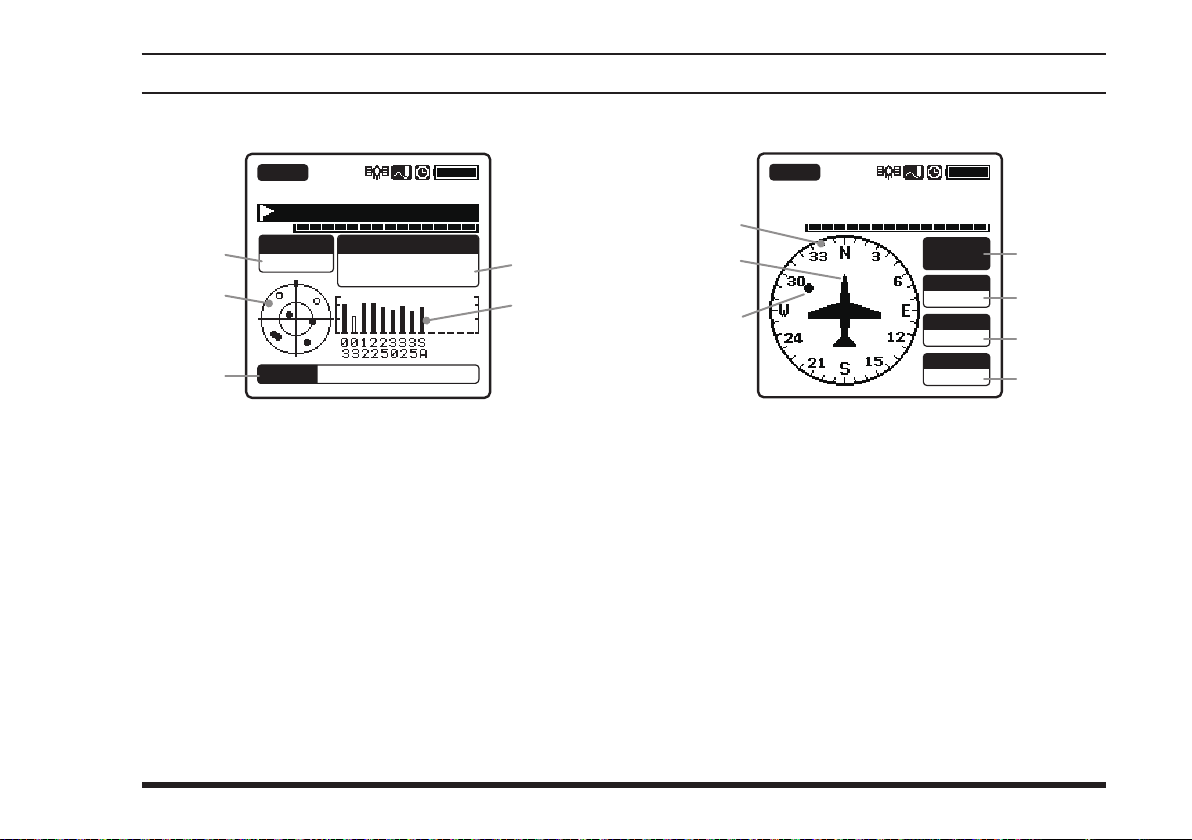
lcd dIsplay (Fta-750 only
)
gps status screen
BUSY
MR
FLG
VOL
STATUS
SEARCH
133.800
KLAX-ATIS
LAT/LON
23°56.890N
123°56.890W
Oct/25 09:56AM
GPS receiver operation status
Radar scope for captured GPS satellites
Date obtained from the GPS signal
Latitude and longitude values
GPS signal strength indicator
DATE
WaypoInt naVIgatIon screen
BUSY
MR
ALL
VOL
Compass rose
Course indicator
Destination indicator
Tag name of the destination
DST (distance) value
COG (course over ground) value
SOG (speed over ground) value
133.800
KLAX-ATIS
KLAX
DSTkm
10
COG T
000
SOGkph
360
°
FTA-750/FTA-550 OperATing MAnuAl
11
Page 14
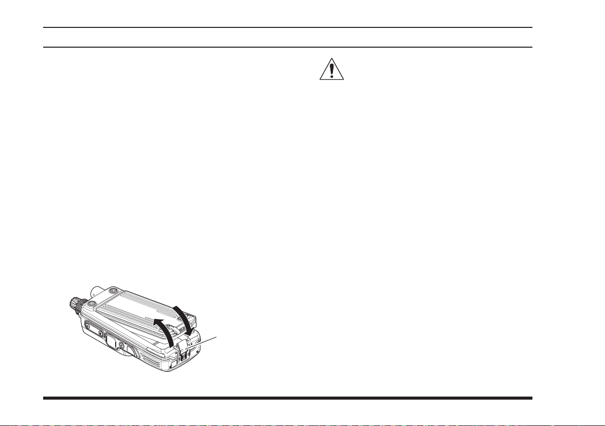
BeFore you BegIn
Battery Installation and Removal
To install the battery, insert the battery pack
into the battery compartment on the back of
12LI
transceiver
the
while pressing the battery pack latch on the bottom of the
the locking plate beside the latch until the entire
“LOCK” appears
Note:
Be sure that the rubber gasket on the
not loose when inserting.
To remove the battery, turn the
the locking plate until the
tirely
, lift up the
the battery pack latch, then pull out the battery from
the radio.
, press the end of the battery pack
transceiver
, then lock the pack by sliding
.
transceiver
“UNLOCK” appears
end of the battery pack by pressing
MIC/SP
DATA
EXT
DC
PUSH
SBR-12LI
off, slide
Battery Pack
Latch
SBR-
is
en-
Do not attempt to open any of the rechargeable Lithium-ion packs, as personal injury
or damage to the Lithium-ion pack could
occur if a cell or cells become accidentally shortcircuited.
Note:
To remove the battery pack after the belt clip
SHB-11
is
mounted (see Page 16), lift up the clip before you press
the battery pack latch.
12
FTA-750/FTA-550 OperATing MAnuAl
Page 15
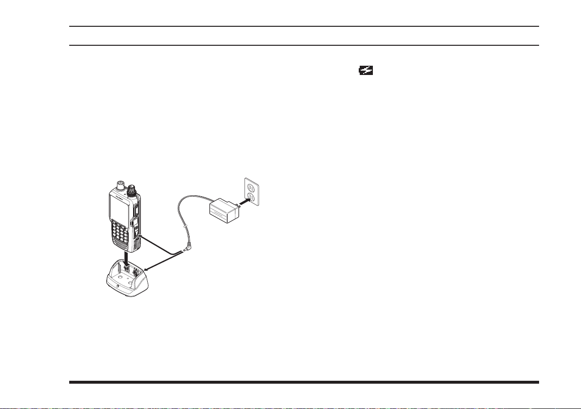
BeFore you BegIn
Battery Charging
It is necessary to charge the Lithium-ion battery fully
before its rst use. Follow the procedure below:
1.
Install the Lithium-ion battery pack onto the transceiver. Ensure that the transceiver is switched off.
2. Insert the cable plug of the
SAD-11
ger into the jack located on the back of the
Charging Cradle, then plug the
line outlet.
VOL
DIAL
MIC/SP
DATA
EXT
DC
SBH-11
3. Insert the transceiver into the
SBH-11
jack should be at the left side when viewing the
cradle from the front.
You may insert the cable plug of the
11
into the
EXT DC
jack located on the right
Battery Char-
SAD-11
SAD-11
SBH-11
into the AC
; the antenna
SAD-
side of the transceiver directly. In this case, the
“ ” icon will appear in the top right corner
of the LCD display.
4. If the transceiver is inserted correctly, the RED indicator on the
A fully-discharged pack will be charged com-
pletely in 4 hours, and then the GREEN indicator on the
It takes 8 hours for full charge with the
11
SBH-11
connected to the transceiver directly.
will glow.
SBH-11
will glow.
Important Notes:
The
SAD-11
is not designed to power the trans-
ceiver for operation (transmission).
Do not leave the charger connected to the trans-
ceiver for continuous periods in excess of 24 hours.
Long term overcharging can degrade the Lithium-
ion battery pack and signicantly shorten its useful
life.
If using a charger other than the
SAD-11, SBH-11
or if using a battery pack other than the
follow the appropriate instructions provided with
the charger/battery. Contact your Dealer if you have
any doubts about the appropriateness of the particular charger or battery pack you intend to use.
SAD-
SBR-12LI
,
,
FTA-750/FTA-550 OperATing MAnuAl
13
Page 16
BeFore you BegIn
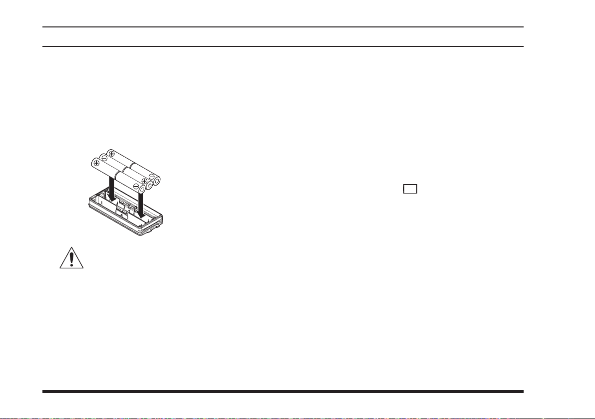
Alkaline Battery Tray Installation
The
supplied
the
FTA-750/FTA-550
battery cells.
When installing a cell, insert the (–) end rst, then
press in the (+) end so the cell snaps into place. Pay
attention to the polarity indicated inside the case.
tion circuits required when utilizing Ni-Cd and NiMH cells.
Note: Replace all six cells at the same time in case of
low battery.
SBT-12
The SBT-12 must not be used with rechargeable cells. The SBT-12 does not contain the thermal and over-current protec-
Battery Tray allows operation of
using six “AA” size alkaline
SBT-12
Alkaline Battery Tray
14
To install the
tery pack first from the transceiver, turn the open
side of the
tery compartment.
Note: Be sure that the rubber gasket on the
is not loose when inserting.
SBT-12
SBT-12
, remove the Lithium-ion bat-
down, then insert it into the bat-
SBT-12
Low Battery Indication
As your battery discharges during use, the voltage will
gradually become lower. When the battery voltage
reaches 6.0 Volts, the “ ” icon will blink on the
LCD display, indicating that the battery pack must be
recharged or the alkaline battery cells must be replaced
before further use.
Avoid recharging Lithium-ion batteries before the
“Low Battery” indicator is observed, as this can
degrade the charge capacity of your Lithium-ion
battery pack. YAESU recommends that you carry an
extra, fully-charged pack with you so you will not
lose communications capability due to a depleted
Lithium-ion battery.
The fully-charged battery lasts for 12 hours on the
FTA-750
conditions below:
Battery saver ... OFF
Operation ratio ... TX:RX:Standby = 6:6:48 (sec)
or 13.5 hours on the
FTA-550
under the
FTA-750/FTA-550 OperATing MAnuAl
Page 17
BeFore you BegIn
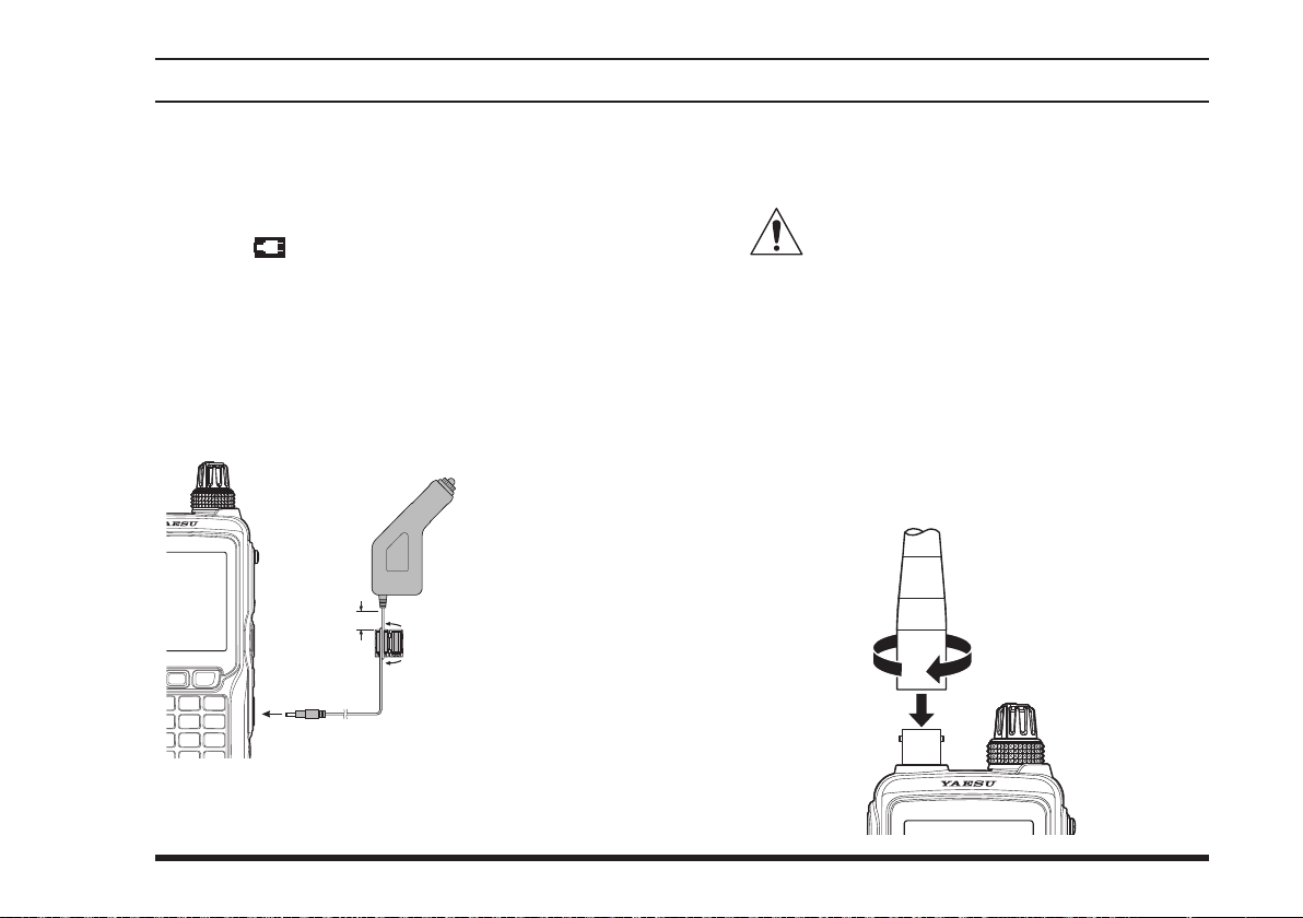
External DC Power Supply Connection
You may insert the cable plug of the optional
Cigarette Lighter DC/DC Converter into the
jack located on the right side of the transceiver. In this
case, the “ ” icon will appear in the top right corner
of the LCD display.
When making DC connections via the
solutely certain to observe the proper voltage level and
polarity guidelines.
The
SDD-12
power sources.
can be connected to 12 to 24 Volt DC
SDD-12
Cigarette Lighter DC/DC
Converter (12 to 24 Volts)
As close
as possible
Ferrite Core
Wind the cable one turn,
then snap two halves
SDD-12
SDD-12
EXT DC
, be ab-
and snap its two halves together, per the illustration
above. Attach the ferrite core as close as possible to
the
SDD-12
body, as shown.
Do not connect any accessory unapproved
by YAESU to supply DC power; otherwise
the
FTA-750/FTA-550
may be damaged.
Antenna Installation
To attach the supplied antenna to the
FTA-550
exert a moderate “pinching” pressure on the base
as you press the antenna onto the radio’s antenna
connector. While exerting this pressure, rotate the
antenna clockwise 1/4 turn to lock the antenna in
place.
, grasp the base of the antenna rmly, and
FTA-750/
For noise reduction from exogenous noise, wind one
turn of the
SDD-12
cable around the ferrite core,
15
FTA-750/FTA-550 OperATing MAnuAl
Page 18
BeFore you BegIn
DATA
MIC/SP
EXT
DC
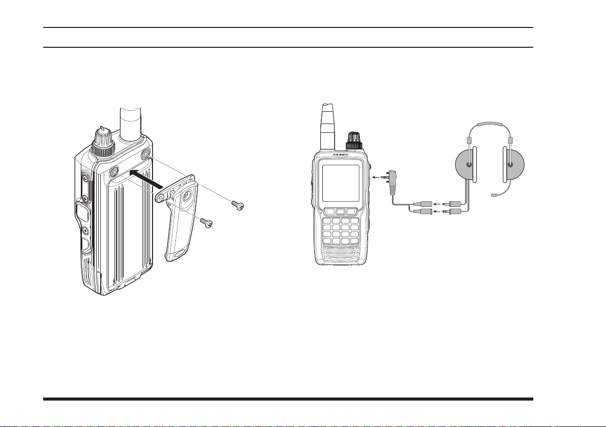
Belt Clip Installation
You may mount the clip to the rear of the
FTA-550
using the supplied screws.
SHB-11
Belt Clip
with two screws (M3 x 8)
FTA-750/
Headset Connection
You may use an optional headset through the supplied
SCU-15
1. Remove the cover and two screws of the
2. Insert the plug of the
3. Fix the plug with two screws attached to the
Headset Adapter Cable (see also Page 84).
Headset
(not supplied)
SCU-15
Headset Adapter Cable
MIC/SP
jack located on the right side of the transceiver.
SCU-15
to the
MIC/SP
jack.
SCU-
.
15
Either of the plug directions are acceptable as
long as the both screws t the screw holes.
4. Insert the plugs of the headset to the sockets of the
SCU-15
.
16
FTA-750/FTA-550 OperATing MAnuAl
Page 19

BeFore you BegIn
Precautions
The
FTA-750/FTA-550
communication on channels used for critical aviation safety communications. Therefore, it is important that this radio be kept away from children or
other unauthorized users at all times.
Do not dispose of the Lithium-ion battery pack in a
re. Do not carry a Lithium-ion battery pack in your
pocket, where keys or coins could short the terminals. This could create a serious fire/burn danger,
and possibly cause damage to the Lithium-ion pack.
The
FTA-750/FTA-550
waterproof capability equivalent to IPX5. Do not
allow the radio to become submerged, and do not
subject it to water spray under pressure.
are capable of two-way
are designed to have the
FTA-750/FTA-550 OperATing MAnuAl
17
Page 20
Reception (COM Band)
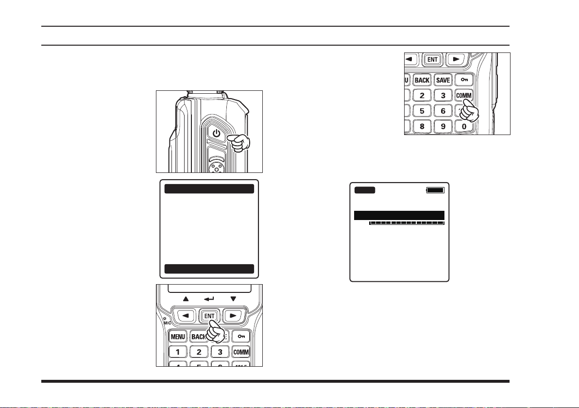
Turning the radio on and off
To turn the radio on,
press and hold the
POWER
“
displayed.
WARNING
switch.
” will be
BasIc operatIon
A channel frequency will
The “
PTT
appear on the display. If
not, press the
key.
BUSY
audio signal is received on the current frequency.
[
COMM
” icon appears on the display when the
]
If you agree with the
warning message, press
the [
ENT
18
] key.
WARNING
This device can only
be used as an aid to
navigation for VFR.
All information
is presented for
reference only.
You assume total
responsibility and
risk associated with
using this device.
I agree
BUSY
127.300
VOL
To turn the radio off, press and hold the
switch.
FTA-750/FTA-550 OperATing MAnuAl
POWER
Page 21
BasIc operatIon
Adjusting the frequency
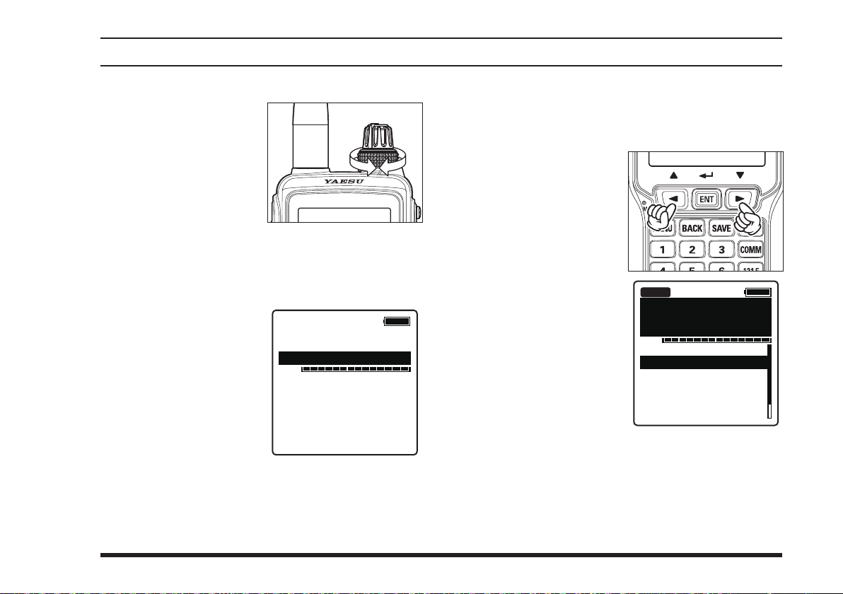
You may turn the
selector (outer) knob on
the top panel to choose
the desired operating
frequency. The channel
frequency will appear
on the LCD.
Directly entering frequencies from the keypad is the
easiest method if you know the frequency on which
you wish to operate. Just enter the ve digits of the
frequency to move to that frequency.
For example, to set
134.35 MHz,
[1]
[1]
.
[5]
[3]
.
[8]
press
[3]
To set 118.275 MHz,
you do not need to
press the nal “5” in the
frequency as below:
[1]
[7]
DIAL
[4]
[2]
13-.---
VOL
You may recall the operating frequency that you
have used by pressing the [
A list of frequencies you have used will appear be-
low the VOL meter on the display.
Select the desired fre-
quency by pressing the
[◄]
press the [
or
[►]
key, then
ENT
] key.
ENT
BUSY
] key.
133.800
VOL
132.400
134.800
127.600
119.150
124.250
129.200
FTA-750/FTA-550 OperATing MAnuAl
19
Page 22
PTT
PTT
BasIc operatIon
Adjusting the volume
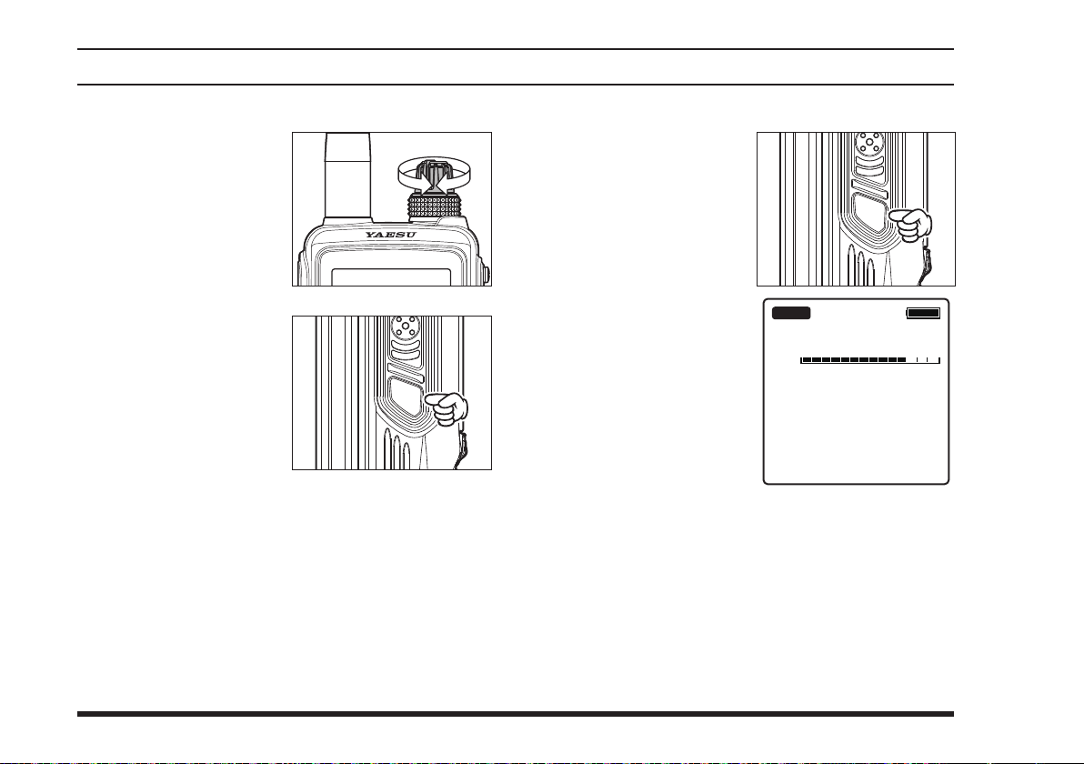
Rotate the
knob to set the volume
level. If no signal is
present, press the
switch; background
noise will now be heard,
and you may use this
noise to set the
knob for the desired
audio level. Press and
hold the
to silence the noise and
resume normal (quiet)
monitoring.
VOL
SQL
(inner)
SQL
VOL
switch
Adjusting the squelch
Press the
then rotate the
selector knob to set the
SQL
squelch threshold (0 to
15) so that the receiver
is just silenced. A higher number indicates that
a higher signal level
is required in order to
open the squelch.
Press and hold the
threshold to 0 (off).
Your new setting will be saved each time you per-
form either of the operations above.
SQL
switch,
DIAL
SQL
SQL
BUSY
127.300
SQL
switch to set the squelch
20
FTA-750/FTA-550 OperATing MAnuAl
Page 23
BasIc operatIon
Monitor Switch
When listening to a very weak signal from an aircraft or
ground station, you may observe the signal disappearing
periodically as the incoming signal strength becomes too
weak to override the squelch threshold setting.
To disable the squelch temporarily, press and hold the
switch for 2 seconds. The squelch will remain
SQL
open and you should have a better chance of hearing
weak signals.
To return to normal operation, press the
tarily.
SQL
momen-
Accessing the 121.5 MHz Emergency Frequency
The
FTA-750/FTA-550
121.500 MHz emergency frequency. This function can
be activated even when the keypad lock function (described on Page 46) is in use.
can quickly access the
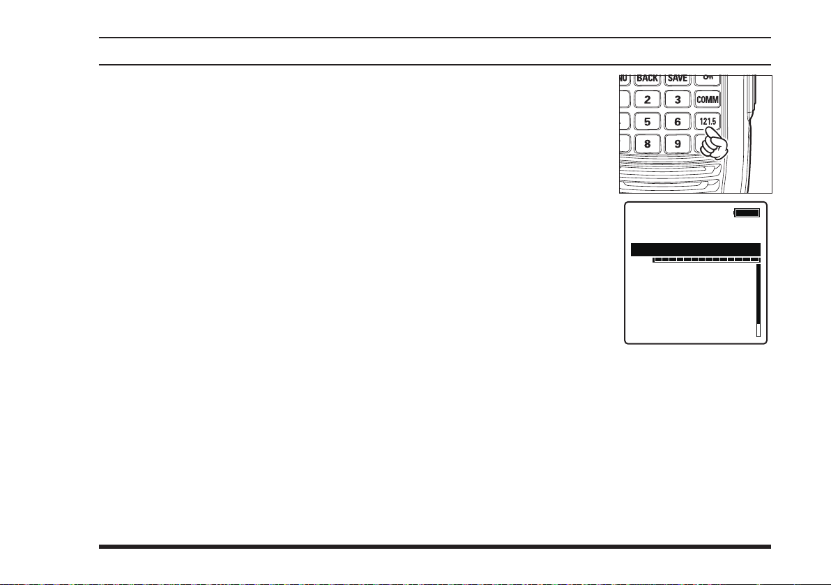
To access the emergen-
cy frequency, press and
[
hold the
After four beeps, the
transceiver enters the
emergency mode and
the frequency is automatically tuned to
121.500 MHz.
To exit the emergency mode, press the
key. The message conrming the cancelation of the
emergency mode will appear. Press the
key to select “
121.5
]
key.
”, then press the
YES
EMG
121.500
EMERGENCY
VOL
132.400
134.800
127.600
119.150
124.250
129.200
[◄]
[
]
key.
ENT
[
COMM
or
[►]
]
FTA-750/FTA-550 OperATing MAnuAl
21
Page 24
BasIc operatIon
Transmission (COM Band)
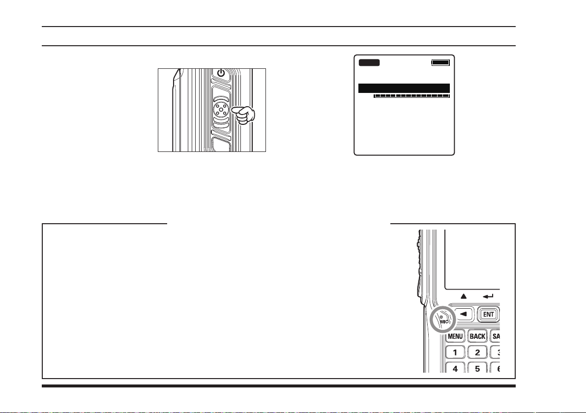
To transmit, press and
hold the
Speak into the microphone area of the front
panel grille in a normal
voice level.
The “
Your
seals around the microphone and speaker enclosure. This requires that you focus your
speech in the direction of the microphone’s location, so as to ensure sufcient voice
input to the radio. Refer to the illustration and observe the location of the internal microphone.
If you nd it difcult to utilize the
speaking directly into the microphone, we recommend the use of the
er/Microphone (option), or an aftermarket aviation headset with boom microphone.
TX
indicates that the
750/FTA-550
the transmit mode, appears on the display.
FTA-750/FTA-550
switch.
PTT
” icon, which
FTA-
are in
PTT
SQL
To return to the receive mode, release the
switch.
Operating Advice: Use of Internal Microphone
are sealed against water ingress, which includes waterproof
FTA-750/FTA-550
conveniently and safely while
SSM-10A
TX
127.300
VOL
Speak-
PTT
22
FTA-750/FTA-550 OperATing MAnuAl
Page 25
BasIc operatIon
Operation Bands
When the
FTA-750/FTA-550
time, it enters the COMM mode and displays the COM
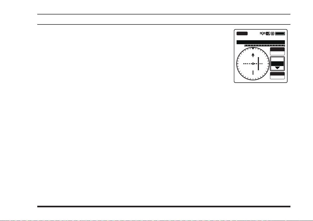
band screen. The COMM mode is the basic operation
mode of the
FTA-750/FTA-550
through either of the NAV and COM bands using the
knob or the keypad.
NAV band (108.000 - 117.975 MHz):
Band for navigation utilizing data signals emitted by
VOR (VHF omnidirectional range) stations and ILS
(instrument landing system) of airports.
COM band (118.000 - 136.975 MHz):
Band for communication utilizing audio signals.
are turned on for the rst
that
allows you to tune
DIAL
When the
550
FTA-750/FTA-
receive a data signal
associated with VOR or
ILS, the display will automatically switch to the NAV
band screen which shows a
CDI (course deviation indicator) based on the received
signal, and “
indicates that the
FTA-550
are on the NAV
band, appears on the display.
NAV
”, which
FTA-750/
NAV VOR
113.600
KLAX-VOR
VOL
N
33
30
24
When receiving a VOR
signal on the FTA-750
21
15
S
OBS
3
000
6
355
EW
FROM
12
SOGKT
°
°
150
FTA-750/FTA-550 OperATing MAnuAl
23
Page 26
BasIc operatIon
Operation Modes
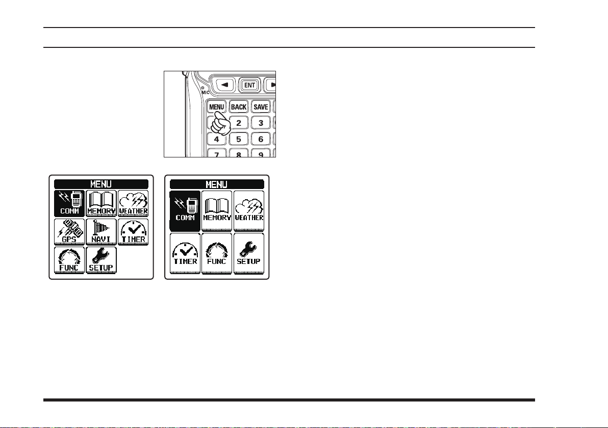
The
FTA-750/FTA-550
erate in either of the modes
below. You can switch the
modes via the
displayed by pressing the
[
MENU
panel.
When turning on the
you have used before turning off will automatically be
entered.
MENU
]
key on the front
FTA-750 FTA-550
op-
screen
FTA-750/FTA-550
, the last mode
COMM
The basic operating mode for communication. Navi-
gation through the NAV band is also performed on
this mode.
MR
This mode provides you with the ability to store and
The receive mode for the VHF weather chan-
The position information and status of the GPS sat-
Navigation to the waypoint (destination) memorized
This mode allows certain aspects of your radio’s
(MEMORY)
recall as many as 200 channels in the radio’s main
memory bank.
WX
(WEATHER)
nel broadcasts. 10 weather channels are pre-programmed at the factory.
GPS
(FTA-750 only)
ellites according to the signals received by the builtin GPS unit are displayed during this mode.
NAVI
(FTA-750 only)
or manually input is carried out in this mode.
SETUP
configuration to be customized for your personal
operating conditions.
24
FTA-750/FTA-550 OperATing MAnuAl
Page 27
BasIc operatIon
Convenient menu items
The
which provide advanced and convenient usage of the
FTA-750/FTA-550
TIMER
You may use the
down timer or a stopwatch through this menu.
FUNCTION
Enables and disables various functions such as scan
and dual watch features through this menu.
screen also includes the following items
MENU
.
FTA-750/FTA-550
as a count-
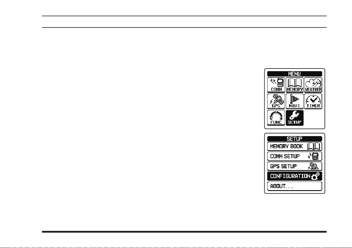
Resetting the Radio
To clear all memories and other settings to factory defaults:
1.
Press the
2. Select
screen by pressing the
[◄]
then press the
key.
3. Select “
TION
pressing the
key, and then press the
[
ENT
[
“
SETUP
[►]
or
CONFIGURA-
” on the screen by
]
key.
MENU
” on the
key, and
[◄]
]
key to display the
[
]
ENT
[►]
or
MENU
screen
.
FTA-750/FTA-550 OperATing MAnuAl
25
Page 28
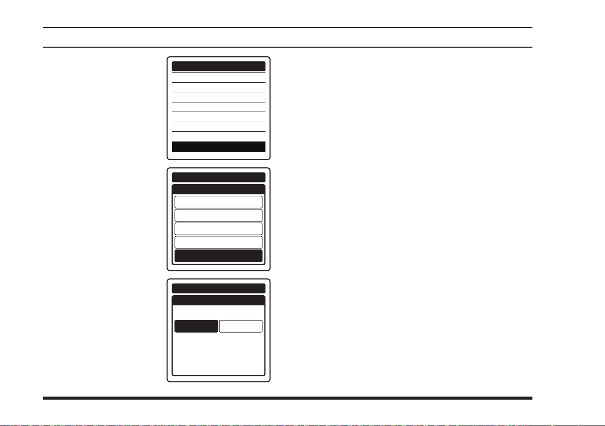
4.
Select
“
RESET
screen by pressing the
[◄]
then press the
key.
or
[►]
key, and
” on the
[
ENT
CONFIGURATION
DIMMER
LAMP
CONTRAST
]
KEY BEEP
TIMER ALARM
BATTERY SAVE
LOCK SELECT
RESET
BasIc operatIon
The initialization will start and then “
will be displayed after the radio returns to factory
default.
COMPLETED!
”
26
5.
Select
the screen
[◄]
the
then press the
key.
6.
Select
screen
[◄]
or
then press the
key.
“
FACTORY
by pressing
[►]
or
“
OK?
by pressing the
[►]
key, and
on
”
key, and
[
ENT
on the
”
[
ENT
CONFIGURATION
]
CONFIGURATION
CONFIGURATION
]
OK?
RESET
FUNCTION
MEMORY
COMM & GPS
FACTORY
RESET
FACTORY
CANCEL
FTA-750/FTA-550 OperATing MAnuAl
Page 29

adVanced operatIon
Reception of VOR Signals
When the
FTA-750/FTA-550
omnidirectional range) signal, the display will automatically switch to the NAV band screen which shows a
CDI (course deviation indicator) based on the received
signal, and “
FTA-550
are receiving the VOR signal, appears on the
”, which indicates that the
VOR
display.
NAV VOR
113.600
Compass rose
Course indicator (OBS direction)
Deviation marks
Course deviation needle
OBS (omni bearing selector) value
VOR value
TO/FROM indicator
SOG (speed over ground) value according to the
KLAX-VOR
VOL
N
33
30
24
21
S
FTA-750 FTA-550
OBS
3
000
°
6
355
°
EW
FROM
12
SOGKT
15
150
GPS signal
receive a VOR (VHF
NAV VOR
113.600
VOL
30
24
KLAX-VOR
33
21
N
S
3
6
EW
12
15
FTA-750/
OBS
000
°
355
°
FROM
FTA-750/FTA-550 OperATing MAnuAl
The OBS is set to 0 degree when you use the
750/FTA-550
for the rst time.
FTA-
The last value you have set as the OBS will be dis-
played next time the NAV band screen appears.
The upside of the compass rose always indicates the
direction set as the OBS.
When the OBS is set to a degree within the “TO”
range relative to the VOR signal, the
FTA-550
displays a degree adding (or subtracting)
FTA-750/
180° to (or from) the VOR signal as the VOR value.
The SOG is displayed only when the internal GPS
unit is activated and receives a x in the
FTA-750
.
Note:
You may change the COM band receive frequency while
[
receiving a VOR signal. If the
]
key is pressed
ENT
during the tag name of the VOR station is selected,
the recall screen listing the frequencies you have used
will temporarily appear on the display, so that you may
select a frequency from the list with the
or change the frequency with the
DIAL
[◄]
selector knob.
or
[►]
key
27
Page 30
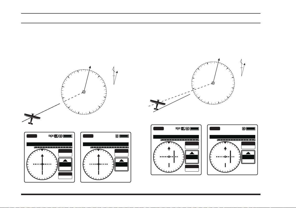
adVanced operatIon
Reading the CDI
If the OBS is set to 50° and your aircraft is at 230°
from a certain VOR station, for example, you are “on
course” and the course deviation needle of the CDI
will be at the center of the compass rose.
VOR 230°
OBS 50°
0°
340°
350°
330°
320°
310°
300°
290°
280°
270°
260°
250°
240°
230°
220°
210°
200°
190°
180°
VOR
Station
170°
10°
20°
130°
140°
150°
160°
N
Magnetic
30°
40°
120°
North
50°
60°
70°
80°
90°
100°
110°
If the OBS is set to 50° but your aircraft is at 236°
from a certain VOR station, for example, you are “off
course” and the course deviation needle of the CDI
will be inside the right half of the compass rose.
VOR 236°
OBS 50°
320°
310°
300°
290°
280°
270°
260°
250°
240°
230°
220°
210°
200°
190°
180°
VOR
Station
170°
10°
20°
130°
140°
150°
160°
0°
340°
350°
330°
N
Magnetic
30°
120°
North
40°
50°
60°
70°
80°
90°
100°
110°
28
NAV VOR
VOL
3
N
33
30
W
24
113.600
KLAX-VOR
6
E
12
15
S
21
OBS
050
TO
050
SOGKT
150
°
°
VOL
33
30
3
N
W
24
113.600
KLAX-VOR
6
E
21
FTA-750 FTA-550
NAV VOR
12
S
15
OBS
050
TO
050
°
°
NAV VOR
VOL
N
33
30
W
113.600
KLAX-VOR
6
3
21
24
OBS
050
E
12
15
S
TO
056
SOGKT
150
°
°
NAV VOR
VOL
N
33
30
W
113.600
KLAX-VOR
6
3
21
24
OBS
050
E
12
15
S
TO
056
°
°
FTA-750 FTA-550
FTA-750/FTA-550 OperATing MAnuAl
Page 31
adVanced operatIon
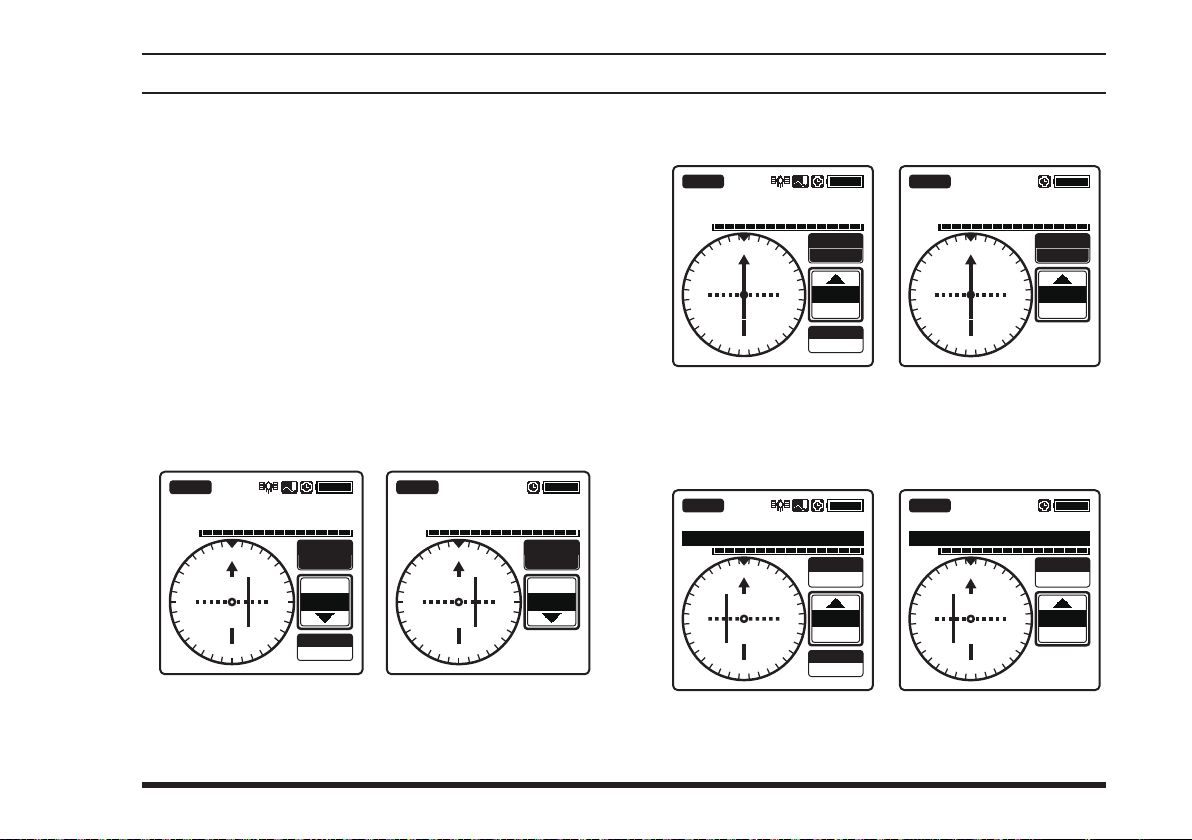
The course deviation needle moves to the right if
your aircraft is off course to the left of the OBS, or
moves to the left if your aircraft is off course to the
right of the OBS.
The deviation marks indicate off-course level by
2 degrees up to 10 degrees per each side. If your
deviation exceeds 10 degrees, the course deviation
needle will stay at the position of the fth mark (the
end of the scale) of the left or right side.
Flying to a VOR station
1. Set the frequency to the desired VOR station
2. Press
the
[◄]
or
[►]
key to
select
screen.
NAV VOR
113.600
KLAX-VOR
VOL
24
30
33
21
N
15
S
OBS
3
000
EW
355
FROM
SOGKT
150
°
°
6
12
FTA-750 FTA-550
NAV VOR
VOL
33
30
24
21
113.600
KLAX-VOR
N
S
“
3
15
OBS
6
EW
12
.
” on the
OBS
000
355
FROM
°
°
3. Enter the course to the VOR station with the keypad
or the
NAV VOR
VOL
15
12
E
6
3
knob.
DIAL
NAV VOR
113.600
KLAX-VOR
S
21
24
W
30
33
N
OBS
175
TO
175
SOGKT
150
°
°
VOL
12
E
6
113.600
KLAX-VOR
S
15
3
N
21
24
30
33
FTA-750 FTA-550
OBS
175
°
TO
W
175
°
4. Correct your course until the course deviation
needle on the screen is at the center of the compass
rose.
NAV VOR
113.600
KLAX-VOR
VOL
S
15
12
E
6
21
3
33
N
OBS
175
24
30
°
TO
W
170
°
SOGKT
150
FTA-750 FTA-550
NAV VOR
VOL
15
12
E
6
3
113.600
KLAX-VOR
S
21
24
W
30
33
N
OBS
175
TO
170
°
°
FTA-750/FTA-550 OperATing MAnuAl
29
Page 32
adVanced operatIon
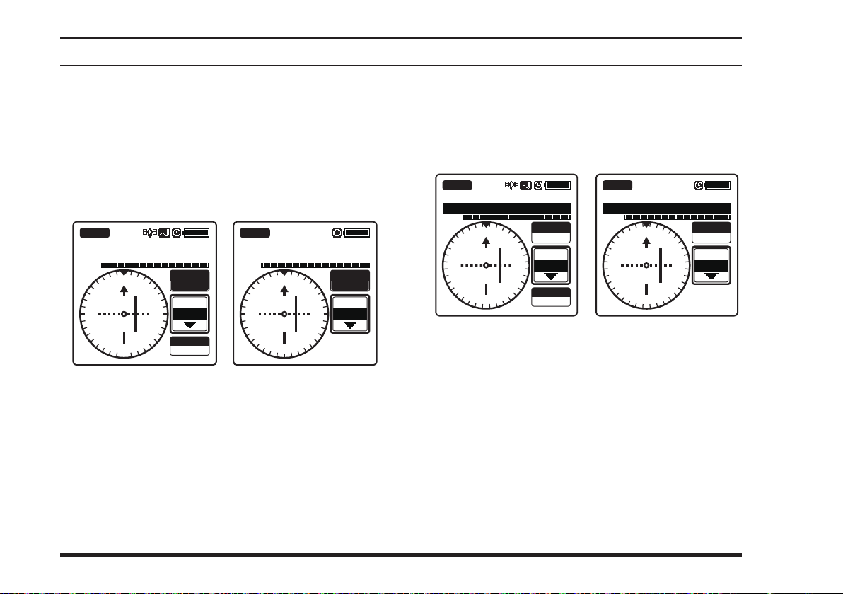
Flying to a desired course
If you know the direction of your destination from a
specic VOR station, you may use the CDI to correct
your course of ying.
1. Set the frequency to the desired VOR station
2. Press
the
[◄]
or
[►]
key to
select
screen.
NAV VOR
113.600
KLAX-VOR
VOL
24
30
33
21
N
15
S
OBS
3
000
EW
355
FROM
SOGKT
150
°
°
6
12
FTA-750 FTA-550
NAV VOR
VOL
33
30
24
21
113.600
KLAX-VOR
N
S
“
3
15
OBS
6
EW
12
.
” on the
OBS
000
°
355
°
FROM
3. Enter the course from the VOR station with the keypad or the
DIAL
knob.
4. Correct your course until the course deviation
needle on the screen is at the center of the compass
rose.
NAV VOR
113.600
KLAX-VOR
VOL
N
33
30
W
24
21
15
S
OBS
3
355
6
12
°
350
°
FROM
E
SOGKT
150
FTA-750 FTA-550
NAV VOR
VOL
33
30
W
24
21
113.600
KLAX-VOR
N
3
6
E
12
15
S
OBS
355
350
FROM
°
°
30
FTA-750/FTA-550 OperATing MAnuAl
Page 33

adVanced operatIon
Reception of ILS Signals
When the
FTA-750/FTA-550
ment landing system) signal, the display will automatically switch to the NAV band screen which shows a
CDI (course deviation indicator) based on the received
signal, and “
FTA-550
are receiving the localizer signal, and “GS”,
”, which indicates that the
LOC
which indicates that the
slope signal, appear on the display.
NAV
LOC GS
108.500
KLAX-RWY07R
VOL
Compass rose
Course (runway) indicator
Deviation marks for localizer
Course deviation needle for localizer
Height deviation indicator for glide slope
Deviation marks for glide slope
N
33
3
30
24
FTA-750 FTA-550
6
EW
12
15
21
S
receive an ILS (instru-
FTA-750/
FTA-750
is receiving the glide
NAV
LOC
108.500
KLAX-RWY07R
VOL
In the
FTA-750
when the internal GPS unit is not
activated or cannot receive a x even it is activated,
or in the
FTA-550
, the upside of the compass rose
always indicates the direction of the runway and
no sign indicating the bearings is displayed on the
compass rose.
In the
FTA-750
when the internal GPS unit is acti-
vated and receives a x, the compass rose rotates to
display the approaching course up. The course indicator, deviation marks, and deviation needle also
rotate to display the runway direction if registered
in advance.
NAV
LOC GS
108.500
KLAX-RWY07R
VOL
Without GPS With GPS, no GS signal,
NAV
LOC
108.500
KLAX-RWY07R
VOL
N
33
21
3
15
S
30
24
runway direction registered
6
EW
12
FTA-750/FTA-550 OperATing MAnuAl
31
Page 34

adVanced operatIon
Note:
You may change the COM band receive frequency
[
while receiving an ILS signal. If the
ENT
]
key is
pressed while the tag name of the airport is selected,
the recall screen listing the frequencies you have used
will temporarily appear on the display, so that you may
[◄]
select a frequency from the list with the
or change the frequency with the
DIAL
selector knob.
or
[►]
key
Terminology:
The localizer signal guides the approach to the
runway in horizontal direction.
The glide slope signal guides the approach to the
runway in vertical direction. Note that some airports
are unequipped with the glide slope.
Guided by
localizer
Localizer
Glide slope
Runway
Course of approach
Guided by
glide slope
Reading the CDI
The course deviation needle moves to the right if
your aircraft is off course to the left of the runway,
or moves to the left if your aircraft is off course to
the right of the runway.
The height deviation indicator moves up if your
aircraft ies lower than the ideal altitude, or moves
down if your aircraft ies higher than the ideal alti-
tude.
High
(GS)
Left
(LOC)
Low
(GS)
CDI Examples Corresponding to Aircraft Location
(Runway is to be at the back of the screen)
Right
(LOC)
On course
32
FTA-750/FTA-550 OperATing MAnuAl
Page 35
adVanced operatIon
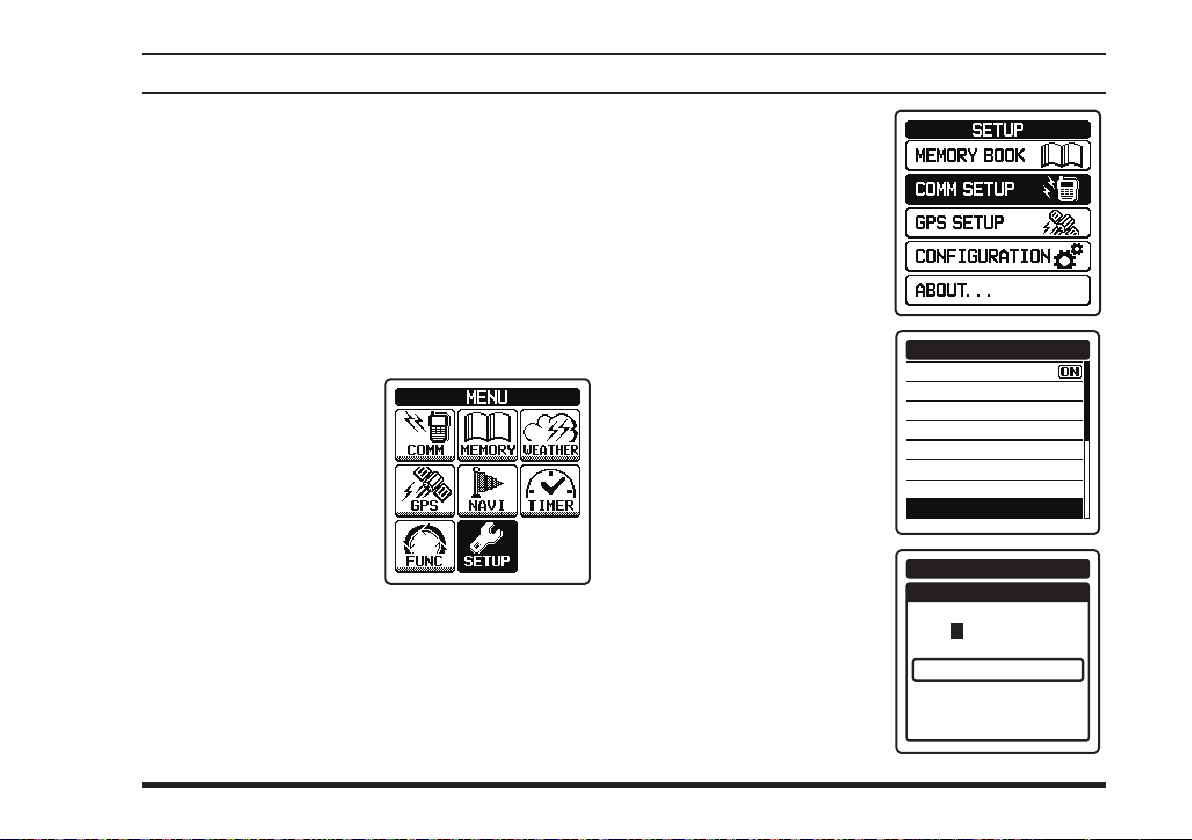
Split Operation
The split operation feature allows you to transmit a call
to a ight service station using the COM band frequencies, while receiving a station in the NAV band. VOR
stations equipped with this capability typically are
shown, on navigation charts, with the voice calling frequency in parenthesis above the navigation frequency.
Programming a transmit frequency
or
[
MENU
“
SETUP
[►]
1.
Press the
2. Select
screen by pressing the
[◄]
then press the
key.
]
key to display the
” on the
key, and
[
]
ENT
MENU
screen
.
3. Select “
UP
pressing the
key, and then press the
[
ENT
4.
Select
QUENCY
by pressing the
[►]
the
5.
Enter the transmit
frequency with the
keypad
COMM SET-
” on the screen by
[◄]
]
key.
“
SPLIT FRE-
” on the screen
key, and then press
[
]
key.
ENT
.
or
[◄]
[►]
or
COMM SETUP
EMERGENCY CALL
ANL
WEATHER ALERT
PTT SCAN STOP
SCAN RESUME
SCAN STOP TYPE
DUAL WATCH FREQ.
SPLIT FREQUENCY
COMM SETUP
SPLIT FREQUENCY
---.---
FINISH
MHz
FTA-750/FTA-550 OperATing MAnuAl
33
Page 36
adVanced operatIon
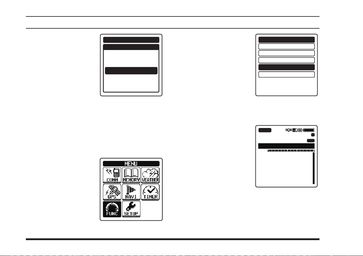
6.
Select
“
FINISH
screen
[◄]
then press the
key.
The frequency will be
determined and the display will return to the
COMM SETUP
Note:
Only the COM band frequencies can be set as the
transmit frequency.
by pressing the
[►]
or
on the
”
key, and
[
ENT
menu.
COMM SETUP
SPLIT FREQUENCY
]
122.100
FINISH
MHz
Activating the split mode
or
[
MENU
“
FUNC
[►]
1.
Press the
2. Select
screen by pressing the
[◄]
then press the
key.
]
key to display the
” on the
key, and
[
]
ENT
MENU
screen
.
3. Select “
screen by pressing the
[◄]
or
then press the
key.
If “ON” is displayed in the right hand of “
the
mode.
The display will return
to the previous screen
and the “
indicates that the
750/FTA-550
the split mode, will appear on the display.
” on the
SPLIT
[►]
key, and
[
]
ENT
FTA-750/FTA-550
” icon, which
±
FTA-
are in
SCAN MEM
DUAL WATCH
SCAN
SPLIT
LOGGER
are already in the split
BUSY
MR
VOL
132.400 Las Vega
FUNCTION
OFF
OFF
OFF
OFF
OFF
SPLIT
133.800
Los Angeles
”,
±
MEM
34
FTA-750/FTA-550 OperATing MAnuAl
Page 37

adVanced operatIon
Operating in the split mode
To transmit a voice call during the NAV band recep-
tion, press and hold the
.
the microphone
played with the frequency you have set.
To exit the split mode,
select “
press the
the
FUNCTION
The COM band screen will be dis-
” and
SPLIT
[
]
key in
ENT
menu.
switch, and speak into
PTT
FUNCTION
SCAN MEM
DUAL WATCH
SCAN
SPLIT
LOGGER
OFF
OFF
OFF
ON
OFF
Reception of Weather Channel Broadcasts
The
FTA-750/FTA-550
nel broadcasts, which may assist your flight planning.
The
FTA-750/FTA-550
of storing 10 weather channels, which simplies access
when you are in an unfamiliar location.
To receive weather
channels, press the
[
MENU
“
WEATHER
screen by pressing the
[◄]
then press the
key.
The last channel you
have tuned will be received.
]
key, select
[►]
or
can receive VHF weather chan-
include a special bank capable
” on the
key, and
[
]
ENT
BUSY
162.475
VOL
162.550 WX01
162.400 WX02
162.475 WX03
162.425 WX04
162.450 WX05
162.500 WX06
WX03
FTA-750/FTA-550 OperATing MAnuAl
35
Page 38
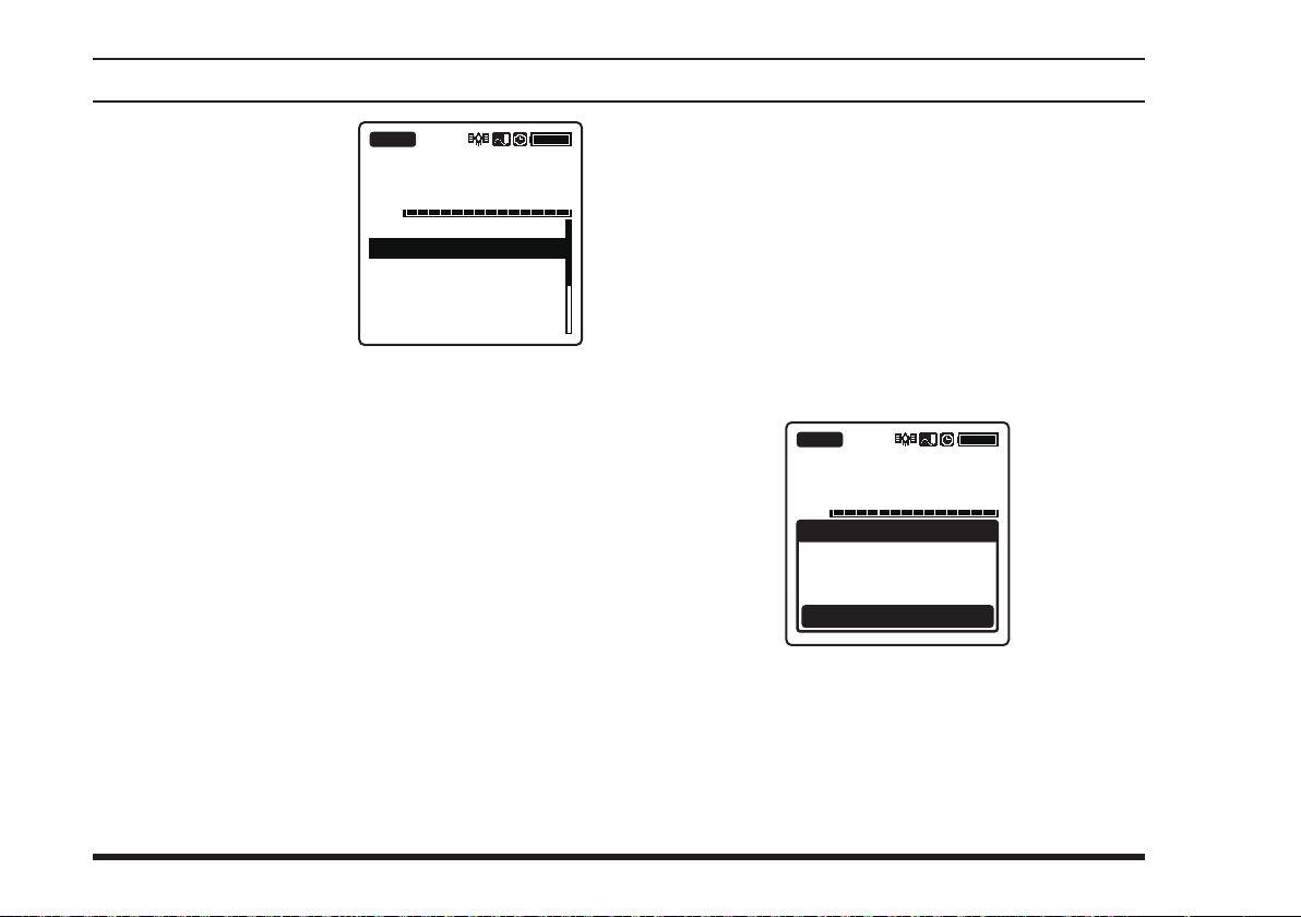
You can also select a
weather channel from
the pre-programmed list
with the
knob.
To conrm the weather
channel frequency selection, press the
key.
To exit the WX mode, press the
lect the mode other than “
by pressing the
[
]
key.
ENT
DIAL
selector
[
ENT
[◄]
or
BUSY
VOL
162.550 WX01
162.400 WX02
162.475 WX03
162.425 WX04
162.450 WX05
162.500 WX06
]
WEATHER
[►]
adVanced operatIon
162.475
WX03
[
MENU
key, and then press the
]
key, se-
” on the screen
Weather alert reception
In the event of extreme weather disturbances, such as
storms and hurricanes, the NOAA (National Oceanic
and Atmospheric Administration) sends a weather alert
accompanied by a 1050 Hz tone and subsequent weather
report on one of the NOAA weather channels.
When the radio receives the weather alert on the operating frequency, it displays a warning as below on the
screen and continues to make alarm sounds until either
of the keys is pressed.
BUSY
162.475
VOL
You may enable or disable the alarm function when receiving the weather alert signal via the
menu, if desired. See Page 69 for details.
WX03
WARNING
Radio received
Weather Alert!
Press any keys
COMM SETUP
36
FTA-750/FTA-550 OperATing MAnuAl
Page 39

adVanced operatIon
Dual Watch Operation
The dual watch feature automatically checks for activity
on the P-ch (priority channel) set via the
menu while you are operating on another channel. During the dual watch operation, the current channel and the
P-ch will be polled alternately for a 200 ms interval.
COMM SETUP
Setting the P-ch
or
[
MENU
“
SETUP
[►]
1.
Press the
2. Select
screen by pressing the
[◄]
then press the
key.
]
key to display the
” on the
key, and
[
]
ENT
MENU
screen
.
3. Select “
UP
pressing the
key, and then press the
[
ENT
4.
Select
FREQ.
pressing the
key, and then press the
[
ENT
5.
Enter the frequency you
want to poll, with the
keypad
COMM SET-
” on the screen by
[◄]
]
key.
“
DUAL WATCH
” on the screen by
[◄]
]
key.
.
or
or
[►]
[►]
COMM SETUP
EMERGENCY CALL
ANL
WEATHER ALERT
PTT SCAN STOP
SCAN RESUME
SCAN STOP TYPE
DUAL WATCH FREQ.
SPLIT FREQUENCY
COMM SETUP
DUAL WATCH FREQ.
---.---
FINISH
MHz
FTA-750/FTA-550 OperATing MAnuAl
37
Page 40

adVanced operatIon
6.
Select
“
FINISH
screen
[◄]
then press the
key.
The frequency will be
determined and the display will return to the
COMM SETUP
by pressing the
[►]
or
on the
”
key, and
[
ENT
menu.
]
Starting the dual watch
or
[
MENU
“
FUNC
[►]
1.
Press the
2. Select
screen by pressing the
[◄]
then press the
key.
]
key to display the
” on the
key, and
[
]
ENT
COMM SETUP
DUAL WATCH FREQ.
127.600
FINISH
MENU
MHz
screen
3. Select “
on the screen by
pressing the
key, and then press the
[
.
The display will return to the previous screen and
the “
FTA-550
pear on the display.
When the radio encounters a signal in the current
channel, it still polls both channels alternately with
longer staying time on the current channel.
When the radio encounters a signal in the P-ch, the
radio stays on the P-ch until the signal disappears,
and the frequency indication on the display blinks.
After the signal disappears, the dual watch resumes.
DUAL WATCH
[◄]
]
key.
ENT
If “ON” is displayed in the right hand of “
WATCH
ing the dual watch.
DW
”, the
” icon, which indicates that the
are performing the dual watch, will ap-
”
[►]
or
FTA-750/FTA-550
SCAN MEM
DUAL WATCH
SCAN
SPLIT
LOGGER
FUNCTION
OFF
OFF
OFF
OFF
OFF
DUAL
are perform-
FTA-750/
38
FTA-750/FTA-550 OperATing MAnuAl
Page 41
adVanced operatIon
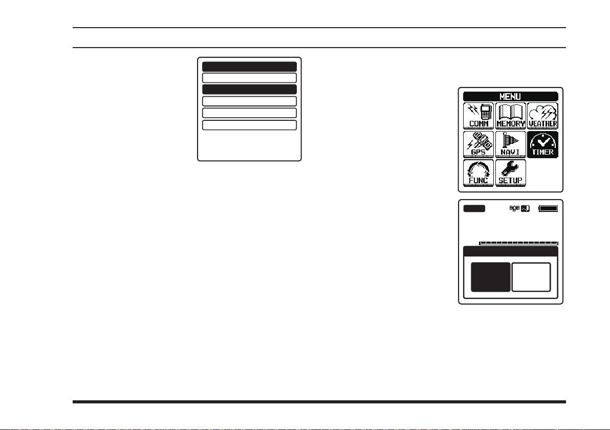
To stop the dual watch,
select “
and press the
key in the
menu.
DUAL WATCH
FUNCTION
[
ENT
”
]
Timer Mode Operation
The
FTA-750/FTA-550
timer and a “Countdown” timer. These can be used for a
variety of time-keeping purposes.
Even while the timer is in operation, you can move to
the other operation modes to receive, transmit, scan, etc.
both provide a “Stopwatch”
FUNCTION
SCAN MEM
DUAL WATCH
SCAN
SPLIT
LOGGER
OFF
ON
OFF
OFF
OFF
Using the stopwatch timer
1.
Press the
2. Select
screen by pressing the
[◄]
then press the
key.
3. Select “
on the screen by
pressing the
key, and then press the
[
ENT
[
“
TIMER
[►]
or
STOPWATCH
]
key.
MENU
” on the
key, and
[◄]
]
key to display the
[
]
ENT
”
[►]
or
VOL
MENU
BUSY
127.300
TIMER
STOP
WATCH
COUNT
DOWN
screen
.
FTA-750/FTA-550 OperATing MAnuAl
39
Page 42
adVanced operatIon
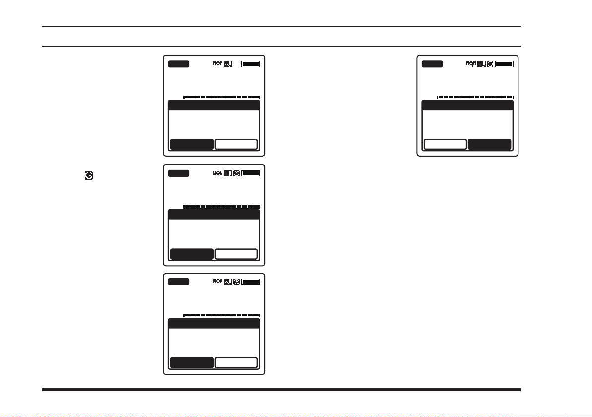
4. To start the counting,
select
“
START
screen by pressing the
[◄]
or
then press the
key.
The displayed time will
increase and “
changes to “
The “ ” icon appears
on the top right of the
display while counting.
5. To stop the counting,
select
“
STOP
[
the
ENT
To resume the count-
ing, select “
changed from “
and press the
key again.
[►]
key, and
STOP
” and press
]
key.
” on the
[
ENT
START
”.
START
STOP
[
ENT
”
”
”
BUSY
127.300
VOL
]
BUSY
TIMER
STOPWATCH
00:00:00
START
127.300
VOL
BUSY
TIMER
STOPWATCH
00:00:03
STOP
127.300
VOL
]
TIMER
STOPWATCH
00:01:53
START
RESET
RESET
RESET
6. To clear the count,
select
“
RESET
screen
[◄]
then press the
key.
by pressing the
[►]
or
on the
”
key, and
[
ENT
BUSY
127.300
VOL
]
STOPWATCH
TIMER
00:01:53
START
If “
continue to count from “
If “
time will be changed to “
will keep stopping.
Note:
You may change the receive frequency while counting.
Select the tag name field with the
then press the
listing the frequencies you have used temporarily on the
display, so that you may select a frequency from the list
with the
the
DIAL
” is selected while counting, the timer will
RESET
00:00:00
” is selected while stopping, the displayed
RESET
00:00:00
[
]
key to display the recall screen
ENT
[◄]
selector knob.
or
[►]
key or change the frequency with
RESET
”.
” and the timer
[◄]
or
[►]
key,
40
FTA-750/FTA-550 OperATing MAnuAl
Page 43
adVanced operatIon
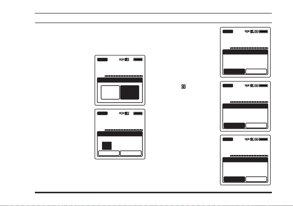
Using the countdown timer
1.
Press the
2. Select
or
3. Select “
on the screen by
pressing the
key, and then press the
[
ENT
4. Input the time with the
keypad or the
selector knob, and then
press the
Press the
key to move the cursor
to hour, minute, or second.
Press the
to cancel the input time.
[
MENU
“
TIMER
[►]
key, and then press the
COUNTDOWN
]
key.
[
]
key to display the
” on the screen by pressing the
”
BUSY
[◄]
[►]
or
VOL
BUSY
DIAL
ENT
[◄]
[
BACK
]
key.
or
[►]
]
key
VOL
screen
MENU
[◄]
[
]
key.
ENT
127.300
TIMER
STOP
WATCH
COUNT
DOWN
127.300
TIMER
COUNTDOWN
00:00:00
START
RESET
5. To start the counting,
select
.
The displayed time will
The “ ” icon appears
“
screen by pressing the
[◄]
or
then press the
key.
decrease and “
changes to “
on the top right of the
display while counting.
START
[►]
STOP
” on the
key, and
[
ENT
START
”.
BUSY
127.300
VOL
]
”
TIMER
COUNTDOWN
00:04:00
START
BUSY
127.300
VOL
RESET
TIMER
COUNTDOWN
00:03:55
RESET
TIMER
RESET
6. To stop the counting,
select
“
” and press
STOP
[
ENT
]
key.
START
STOP
[
ENT
”
”
the
To resume the count-
ing, select “
changed from “
and press the
key again.
STOP
BUSY
127.300
VOL
COUNTDOWN
00:03:42
]
START
FTA-750/FTA-550 OperATing MAnuAl
41
Page 44

adVanced operatIon
7. To clear the count,
select
“
RESET
screen
[◄]
then press the
key.
The displayed time
will be changed to
“
timer will stop.
Note:
You may change the receive frequency while counting.
Select the tag name field with the
then press the
listing the frequencies you have used temporarily on the
display, so that you may select a frequency from the list
with the
the
DIAL
by pressing the
[►]
or
00:00:00
[◄]
or
selector knob.
on the
”
key, and
[
ENT
” and the
[
]
key to display the recall screen
ENT
[►]
key or change the frequency with
BUSY
127.300
VOL
]
TIMER
COUNTDOWN
00:01:53
START
[◄]
RESET
or
[►]
key,
When the count-
down timer reaches
“
00:00:00
will continuously sound
and “
will be displayed on the
screen. Press any key to
stop the beeps.
You can set the timer to alarm without beeps. Select
“
OFF
FIGURATION
”, the beeps
Timer Alarm!
” on the item “
menu in the SETUP mode.
CONFIGURATION
DIMMER
LAMP
CONTRAST
KEY BEEP
TIMER ALARM
BATTERY SAVE
LOCK SELECT
RESET
BUSY
127.300
VOL
”
TIMER ALARM
TIMER
Timer Alarm!
Press any keys
CONFIGURATION
TIMER ALARM
” of the
ON
OFF
CON-
42
FTA-750/FTA-550 OperATing MAnuAl
Page 45
adVanced operatIon
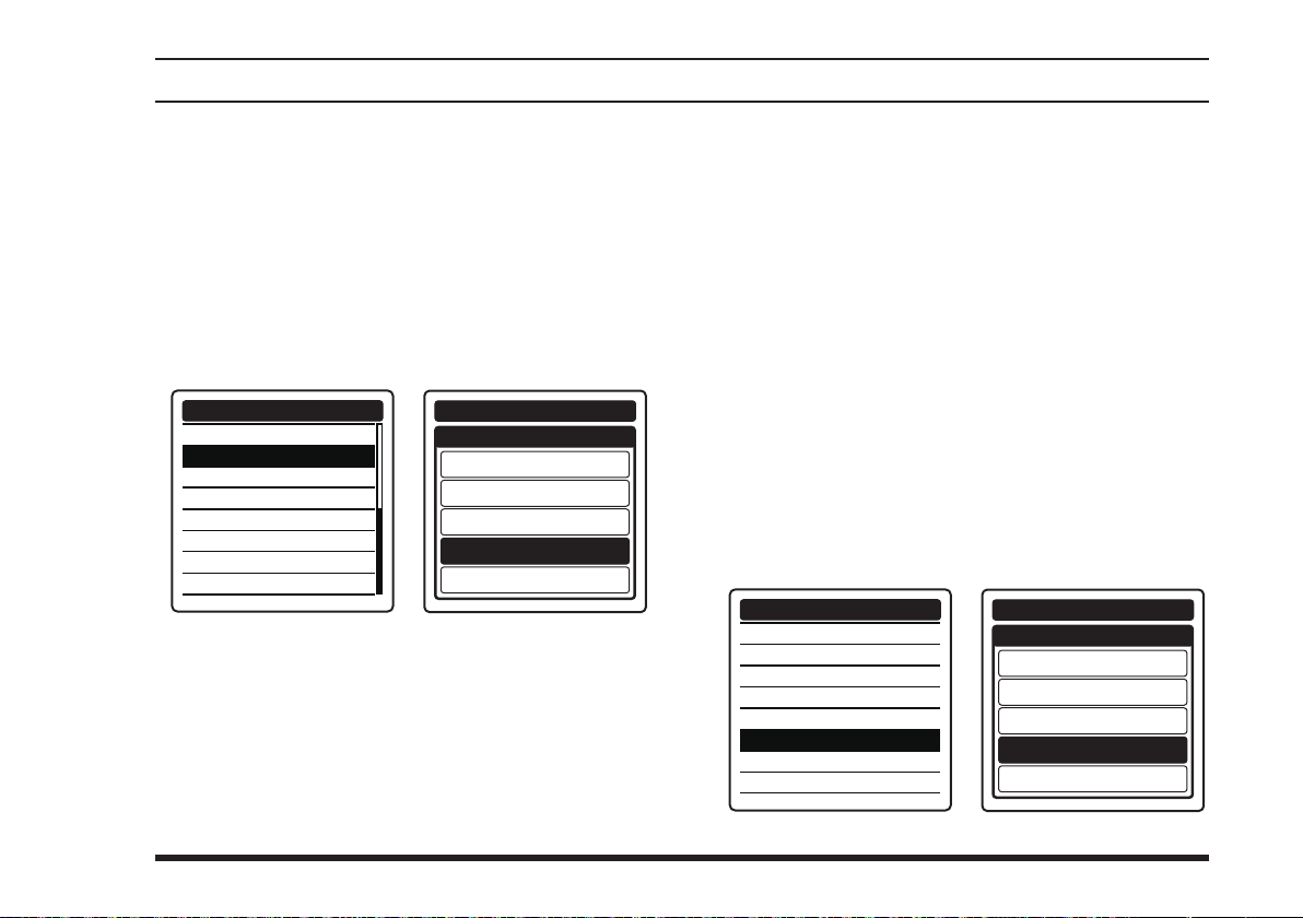
TOT Feature
The TOT (time-out timer) shuts off the transceiver after
continuous transmission exceeds the programmed time.
This feature prevents unintended transmission by mistake and reduces battery consumption.
To activate the TOT, select either of “
“
”, “
3min
menu in the SETUP mode.
SETUP
COMM SETUP
FREQUENCY STEP
TX TOT
AF PITCH CONT.
MIC SELECT
SIDE TONE
VOX
VOX LEVEL
VOX DELAY
” on the item “
5min
TX TOT
COMM SETUP
”, “
1min
” of the
TX TOT
OFF
1min
2min
3min
5min
”,
2min
COMM
Saving the Battery during Reception
One of the important features of the
are its battery saver, which “puts the radio to sleep”
550
for a time interval, periodically “waking it up” to check
for activity. If somebody is talking on the channel, the
FTA-750/FTA-550
then resume its “sleep” cycles. This feature signicantly
reduces quiescent battery drain.
To activate the battery saver, select one of the following
interval time ratios on the item “
CONFIGURATION
... Sleeps for 100 ms after 100 ms awake
50%
... Sleeps for 250 ms after 100 ms awake
70%
... Sleeps for 450 ms after 100 ms awake
80%
... Sleeps for 900 ms after 100 ms awake
90%
will remain in the “awake” mode,
menu in the SETUP mode.
CONFIGURATION
DIMMER
LAMP
CONTRAST
KEY BEEP
TIMER ALARM
BATTERY SAVE
LOCK SELECT
RESET
FTA-750/FTA-
BATTERY SAVE
CONFIGURATION
BATTERY SAVE
OFF
50%
70%
80%
90%
” of the
FTA-750/FTA-550 OperATing MAnuAl
43
Page 46
adVanced operatIon
Using the Headset Microphone
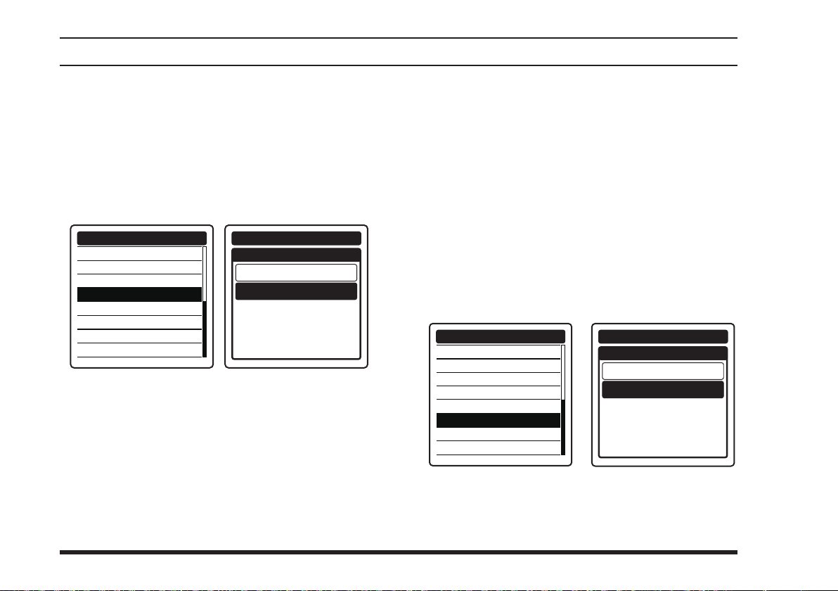
If you want to use the microphone of an aviation
headset prepared by yourself, change the assignment of
microphone controlled with the
To assign the headset microphone, select “
the item “
the SETUP mode.
MIC SELECT
” of the
COMM SETUP
FREQUENCY STEP
TX TOT
AF PITCH CONT.
MIC SELECT
SIDE TONE
VOX
VOX LEVEL
VOX DELAY
When an optional aviation headset is connected, the
switch on the radio will activate the headset micro-
PTT
phone for transmission.
Note:
If you nd it difcult to use the
dio, we recommend to use an aftermarket external PTT
switch. See also Page 84 for details.
switch.
PTT
EXT MIC
COMM SETUP
COMM SETUP
MIC SELECT
INT MIC
EXT MIC
switch of the ra-
PTT
44
” on
menu in
VOX Operation
If you want to have both hands free, use a headset and
activate the VOX (voice-actuated transmit/receive
switching) system.
Notes:
The VOX system does not function when using just
the internal microphone; an external headset must
be used.
Do not activate the VOX system when connecting
the optional microphone
To activate the VOX system, select “ON” on the
item “
UP mode.
VOX
” of the
SSM-10A
COMM SETUP
COMM SETUP
FREQUENCY STEP
TX TOT
AF PITCH CONT.
MIC SELECT
SIDE TONE
VOX
VOX LEVEL
VOX DELAY
The “V” icon, which indicates that the VOX system
is active, will appear at the right side of the channel frequency when the display returns to the COM
band screen.
.
menu in the SET-
COMM SETUP
VOX
OFF
ON
FTA-750/FTA-550 OperATing MAnuAl
Page 47
To adjust the VOX
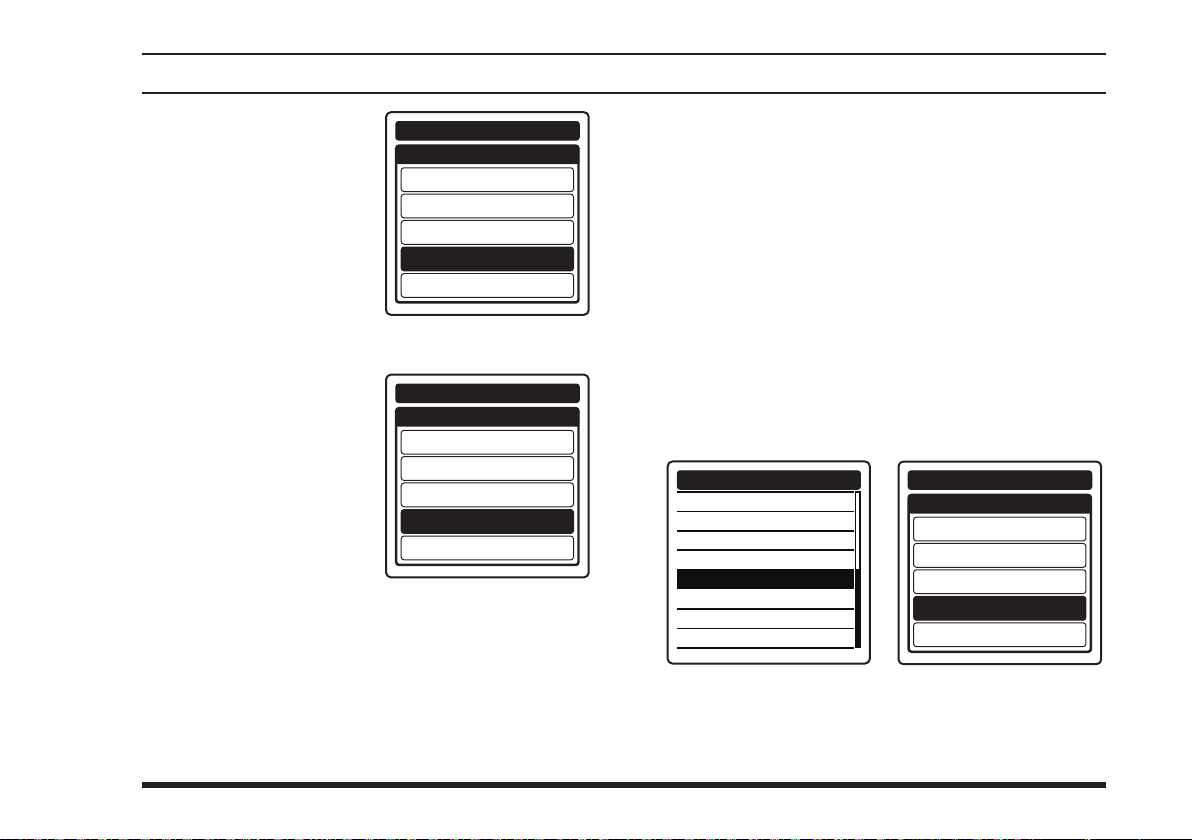
gain, select one of the
following gain levels on
the item “
of the
menu in the SETUP
mode.
MIN / LEVEL1 /
LEVEL2 / LEVEL3 /
MAX
To set the VOX delay,
select one of the following times on the item
“
VOX DELAY
COMM SETUP
the SETUP mode.
0.5sec / 1.0sec /
1.5sec / 2.0sec /
3.0sec
VOX LEVEL
COMM SETUP
” of the
menu in
adVanced operatIon
COMM SETUP
VOX LEVEL
”
MIN
LEVEL1
LEVEL2
LEVEL3
MAX
COMM SETUP
VOX DELAY
0.5sec
1.0sec
1.5sec
2.0sec
3.0sec
Side Tone Control
When utilizing an external headset, you may monitor
your own voice talking to the microphone through the
headphone.
Note:
Do not activate the side tone function when connecting
the optional microphone
To activate the monitoring of your voice (side tone),
select one of the following side tone level on the
item “
SIDE TONE
the SETUP mode.
MIN/LEVEL1/LEVEL2/MAX
SSM-10A
” of the
COMM SETUP
FREQUENCY STEP
TX TOT
AF PITCH CONT.
MIC SELECT
SIDE TONE
VOX
VOX LEVEL
VOX DELAY
.
COMM SETUP
COMM SETUP
SIDE TONE
OFF
MIN
LEVEL1
LEVEL2
MAX
menu in
FTA-750/FTA-550 OperATing MAnuAl
To change the side tone level temporarily during
the monitoring, rotate the
pressing and holding the
selector knob when
DIAL
switch.
PTT
45
Page 48
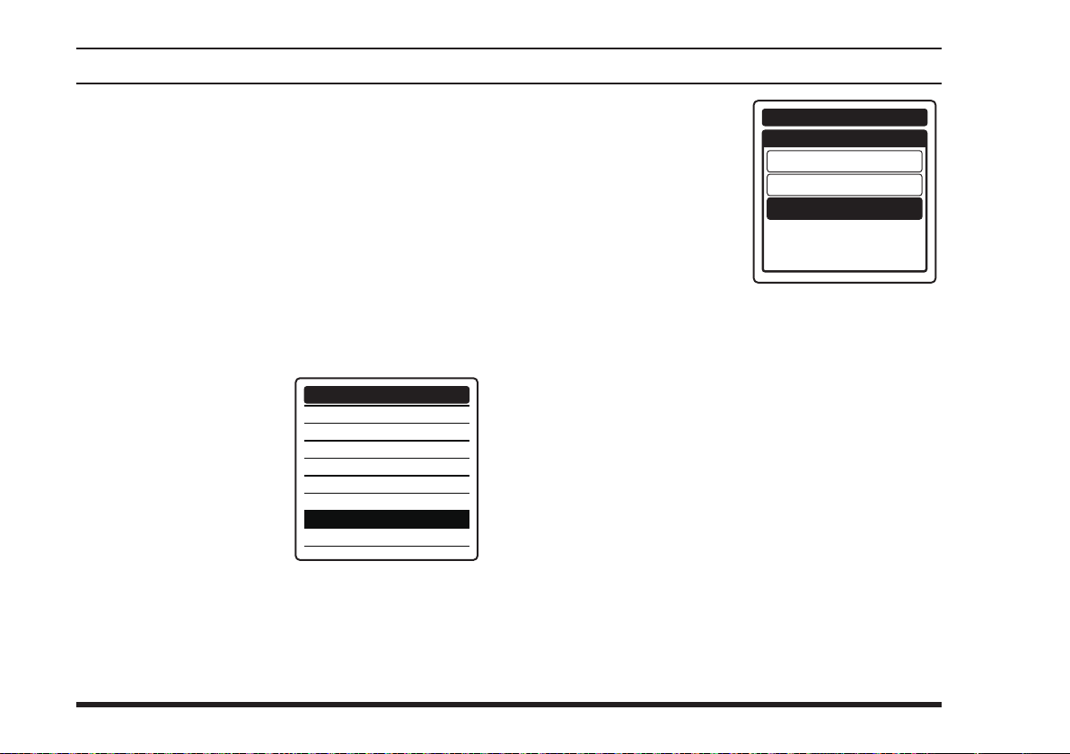
adVanced operatIon
Lock Function
This function prevents accidental changes to the frequency setting and the keypad controls.
Setting the lockout conguration
You may choose the controls to be locked.
1.
Press the
2. Select
or
3. Select “
the
4. S
elect
on the screen by pressing the
key, and then press the
[
ENT
[
MENU
“
SETUP
[►]
key, and then press the
CONFIGURATION
[◄]
or
“
LOCK SELECT
[◄]
]
key.
]
key to display the
” on the screen by pressing the
” on the screen by pressing
[►]
key, and then press the
”
or
[►]
DIMMER
LAMP
CONTRAST
KEY BEEP
TIMER ALARM
BATTERY SAVE
LOCK SELECT
RESET
MENU
[
]
key.
ENT
CONFIGURATION
[
ENT
screen
[◄]
]
key.
5. Select one of the following lock configuration by pressing the
[►]
or
press the
KEY LOCK /
.
DIAL LOCK /
ALL LOCK
The setting will be determined and the display will
return to the
key, and then
[
ENT
[◄]
]
key.
CONFIGURATION
CONFIGURATION
LOCK SELECT
DIAL LOCK
menu.
KEY LOCK
ALL LOCK
46
FTA-750/FTA-550 OperATing MAnuAl
Page 49

adVanced operatIon
Activating the lock feature
Press and hold the
]
[
key.
According to the setting
of the lockout configuration, either of “
”, “
LOCK
or “
pear on the screen for
2 seconds and then the
display will return to
the previous screen.
DIAL LOCK
ALL LOCK
KEY
”,
” will ap-
While the
trols with the
except the
the
If the
the keys is pressed, either of “
LOCK
for 2 seconds and then the display will return to the
previous screen.
To turn the lock feature
off, press and hold the
[
“
UNLOCK
pear on the screen for
2 seconds and then the
display will return to
the previous screen.
FTA-750/FTA-550
PTT
[
]
key are disabled.
121.5
selector knob is rotated or any of
DIAL
”, or “
ALL LOCK
] key again.
” will ap-
selector knob and/or the keys
DIAL
switch, the
” will appear on the screen
are locked, the con-
POWER
switch, and
DIAL LOCK
”, “
KEY
FTA-750/FTA-550 OperATing MAnuAl
47
Page 50
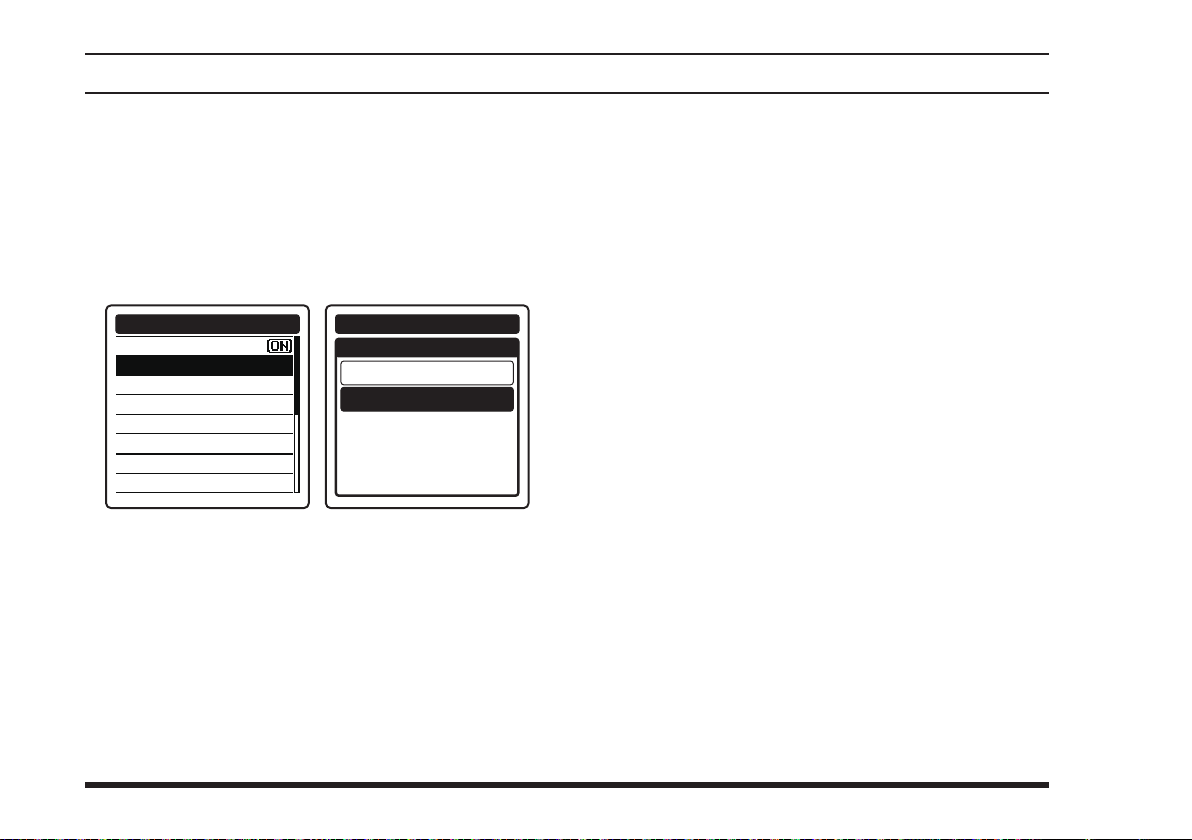
adVanced operatIon
ANL Feature
For reduction of impulse noise, such as that produced by
an engine’s ignition system, the ANL (automatic noise
limiter) feature may prove helpful.
To activate the ANL, select “ON” on the item “
the
COMM SETUP
COMM SETUP
EMERGENCY CALL
ANL
WEATHER ALERT
PTT SCAN STOP
SCAN RESUME
SCAN STOP TYPE
DUAL WATCH FREQ.
SPLIT FREQUENCY
menu in the SETUP mode.
COMM SETUP
48
ANL
OFF
ON
ANL
” of
FTA-750/FTA-550 OperATing MAnuAl
Page 51
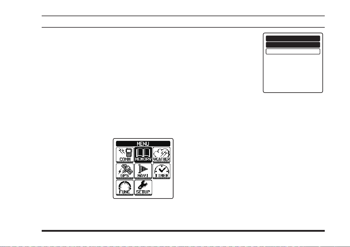
memory operatIon
The
FTA-750/FTA-550
ble memories which can hold sets of information about
channels such as its channel frequency, position infor-
mation, channel tag (name) up to 15 characters, and ag
(marking for search renement).
The stored channels can be assigned to the priority
group which can be named with up to 10 characters.
The
FTA-750/FTA-550
store, label, and recall channel frequencies you may use
frequently.
provide 200 user-programma-
’s memory system allows you to
Recalling the Memories
1. Press
2.
Select
the screen by pressing
the
then press the
key.
the
“
[◄]
[
MEMORY
or
MENU
[►]
key, and
]
key to display the
” on
[
]
ENT
MENU
screen.
3. Select a group that the
desired channel belongs
to, by pressing the
[►]
or
key followed by
[
the
]
key.
ENT
The memory channels belong to either of the
following groups.
... Group including all the memory chan-
ALL
nels
... Group of memory channels you have
FLAG
[◄]
set the item “
ing
MEMORY BOOK
ALL
FLAG
” to “
Flag
Yes
” when stor-
FTA-750/FTA-550 OperATing MAnuAl
49
Page 52
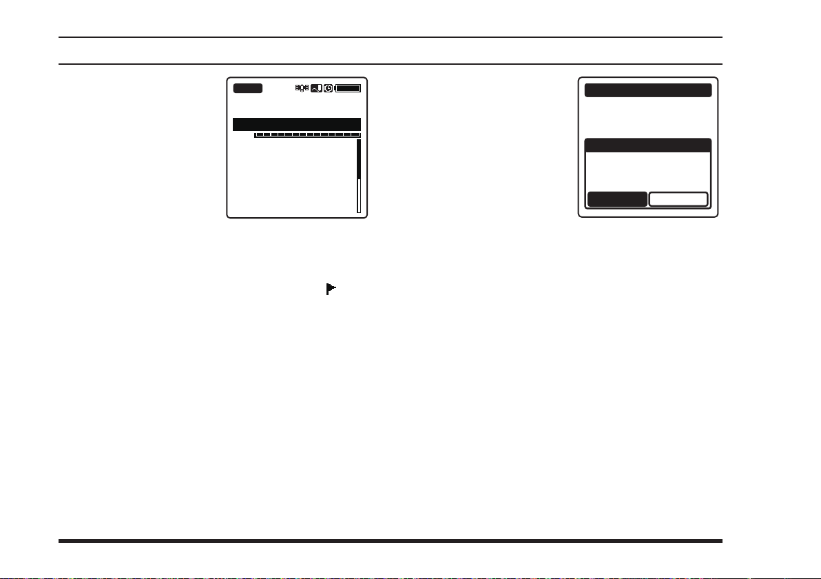
memory operatIon
The frequency and
tag name of the channel listed first, “MR”
which indicates that the
FTA-750/FTA-550
are in the MR (memory
recall) mode, and the
group name selected in
step 3 will appear on
the upper field of the
display.
If the channel has the setting of ag, the “
will appear at the left side of its tag name.
The list of memory channels will also appear below
the VOL meter on the display. You may move to the
list by pressing the
to one of the channels in the list by pressing the
[►]
or
key followed by the
[
BUSY
MR
ALL
133.800
Los Angeles
VOL
133.800 Los Ange
121.650 KLAX-TWR
121.750 KLAX-DEP
120.950 Kansas
124.300 Las Vega
125.200 KLAS-APP
]
key, then select and tune
ENT
[
]
key.
ENT
” icon
[◄]
If you have not yet
stored any memory
channel, a dialog box
titled “
will appear, which asks
whether you want to
make an entry. Select
“
[
ENT
ory channel entries.
See Page 52 for the detailed procedure of storing
channel information.
To exit the MR mode, press the
No Address
” and press the
YES
]
key to add mem-
”
MEMORY BOOK
No Address
Do you make a
memory book?
YES
[
COMM
]
key.
NO
50
FTA-750/FTA-550 OperATing MAnuAl
Page 53
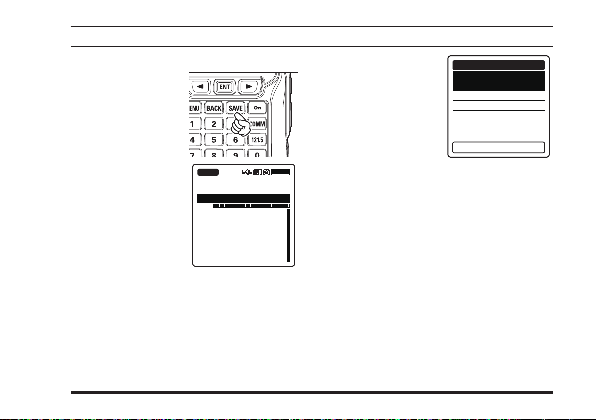
Instant Storage
Select a desired fre-
quency in the COMM
mode, then press the
[
]
SAVE
The frequency will be
stored and a tag name
automatically assigned
will appear on the display.
key.
memory operatIon
BUSY
127.600
VOL
132.400 Las Vega
120.950
133.800
001FRQ
If you want to custom-
ize the information to
be stored, press and
hold the
The
form appears on the display, with the channel
name (tag), frequency,
flag, and position information (if exists)
already lled.
Press the
press the
Input letters and/or numerics with the keypad or the
DIAL
or
inputs or changes have been done, select “
[SAVE] KEY
[◄]
them into the memory.
[
MEMORY BOOK
[◄]
[
ENT
selector knob, or select a setting with the
[►]
key, then press the
[►]
or
]
SAVE
key.
[►]
or
” at the bottom of the display with the
key, then press the
key to select the item, then
]
key.
MEMORY BOOK
Name:
001FRQ_________
Freq.:127.600
Flag:No
LAT --˚--.--LON ---˚--.---
MHz
-
-
Press [SAVE] key
[◄]
[
]
key. After all the
ENT
PRESS
[
]
key to store
ENT
FTA-750/FTA-550 OperATing MAnuAl
51
Page 54
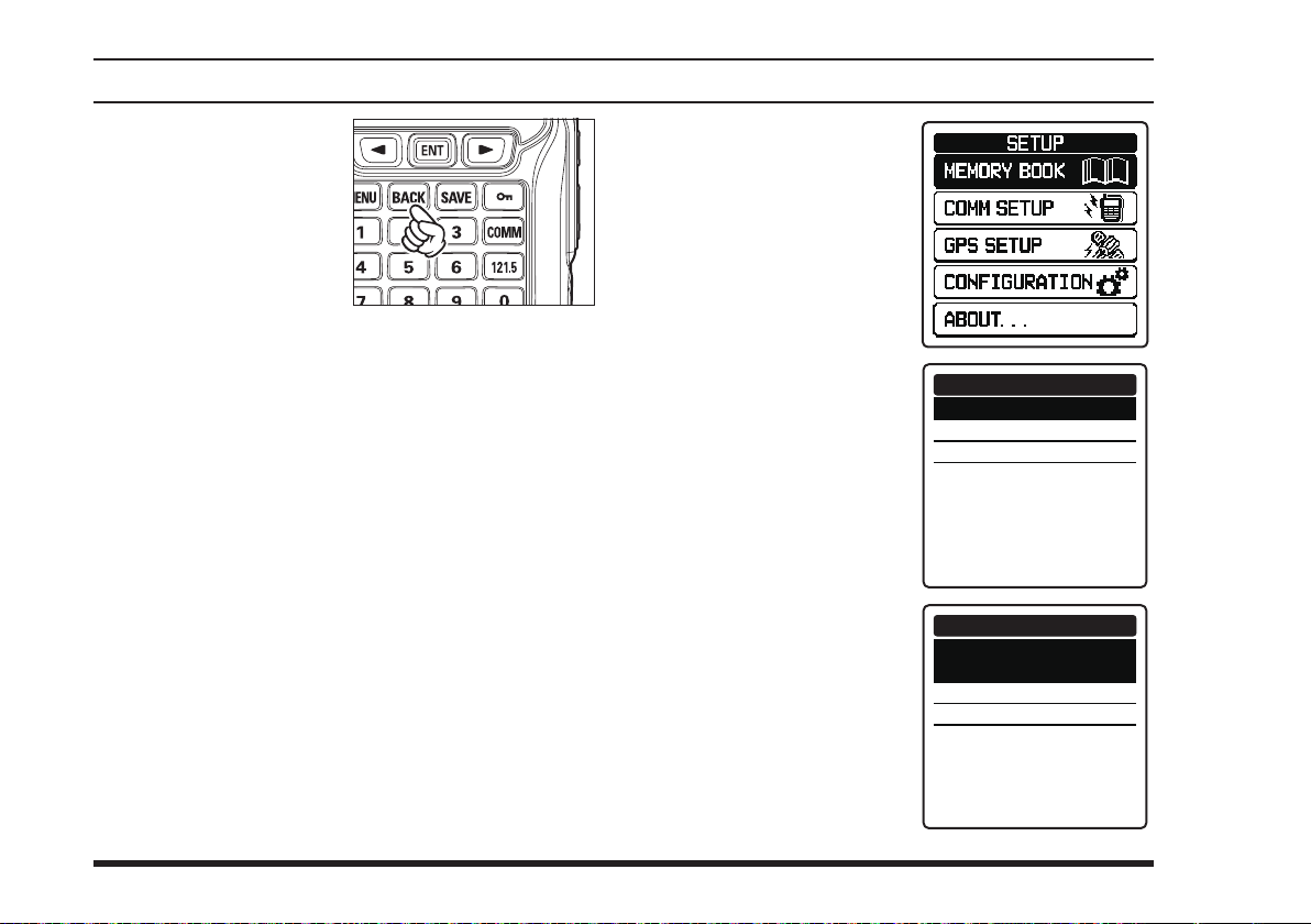
memory operatIon
Press the
to cancel the changes or
inputs.
Note:
You cannot store weather channels to the memory by
pressing the
[
[
SAVE
]
BACK
key
]
key during the WX mode.
Maintenance of the Memory
Adding new addresses, editing the stored information,
and deleting the stored addresses are allowed through
the SETUP mode.
Adding entries
1.
Press the
2. Select
[►]
or
[
MENU
“
SETUP
key, and then press the
]
key to display the
” on the screen by pressing the
[
ENT
MENU
]
key.
screen
.
[◄]
3. Select “
” on the screen by
BOOK
pressing the
key, and then press the
[
]
key.
ENT
4. S
elect
“
ADD
ing the
key, and then press the
[
]
key.
ENT
5. Select the item, input
letters and/or numerics, select a setting, and
store the changes in the
same way as the instant
storage described previously.
MEMORY
[◄]
or
” by press-
[◄]
or
[►]
[►]
MEMORY BOOK
ADD
EDIT
DELETE
MEMORY BOOK
Name:
001MEMORY_______
Freq.:---.--Flag:No
LAT --˚--.--LON ---˚--.---
MHz
-
-
52
FTA-750/FTA-550 OperATing MAnuAl
Page 55

memory operatIon
Notes:
You cannot skip the input of “
You must input either of “
cy) or “
the channel).
LAT
” and “
LON
Editing the information
1.
Press the
2. Select
or
3. Select “
the
4. S
elect
ing the
key, and then press the
[
ENT
[
MENU
“
SETUP
[►]
key, and then press the
MEMORY BOOK
[◄]
or
“
EDIT
[◄]
]
key.
]
key to display the
” on the screen by pressing the
[►]
key, and then press the
” by press-
[►]
or
” (channel tag).
Name
” (channel frequen-
Freq.
” (position information of
screen
]
key.
.
[◄]
MENU
[
]
key.
ENT
” on the screen by pressing
[
ENT
MEMORY BOOK
ADD
EDIT
DELETE
[
ENT
[◄]
]
key.
[◄]
[
ENT
5. Press the
key to select the group
including the entry you
want to edit, then press
the
6. Press the
key to select the entry
you want to edit, then
press the
7. Select the item, input letters and/or numerics, select
a setting, and then store the changes in the same
way as the instant storage described previously.
or
or
]
key.
[►]
[►]
MEMORY BOOK
ALL
FLAG
MEMORY BOOK
ALL
CHICAGO
DALLAS
DAYTON
DETROIT
EL TORO
FLORIDA
GUATEMALA
EDIT
EDIT
FTA-750/FTA-550 OperATing MAnuAl
53
Page 56
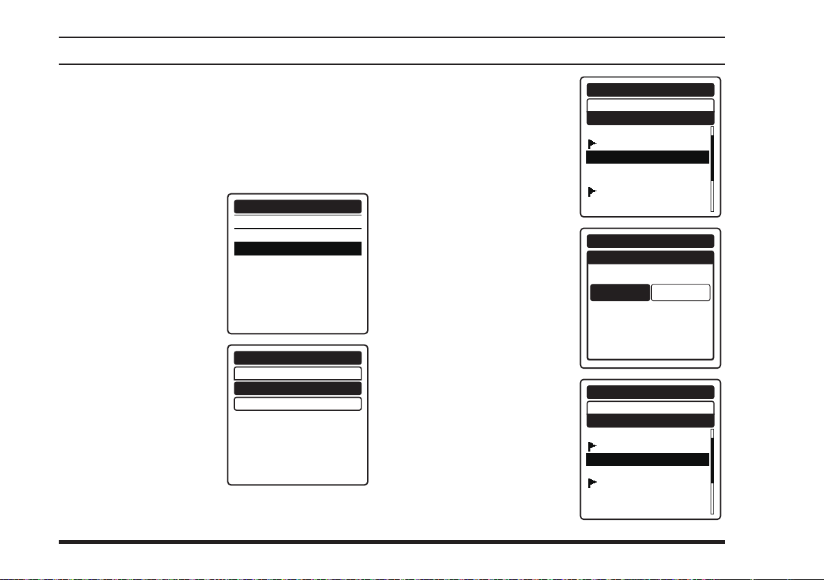
memory operatIon
Deleting the memory
1.
Press the
2. Select
or
3. Select “
the
4. S
elect
pressing the
key, and then press the
[
ENT
5. Press the
key to select the group
including the entry you
want to delete, then
press the
[
MENU
“
SETUP
[►]
key, and then press the
MEMORY BOOK
[◄]
or
“
DELETE
]
key.
[
ENT
]
key to display the
” on the screen by pressing the
[►]
key, and then press the
” b y
[◄]
[►]
or
[◄]
or
]
key.
[►]
screen
MENU
[◄]
[
]
key.
ENT
” on the screen by pressing
[
]
key.
ENT
MEMORY BOOK
ADD
EDIT
DELETE
MEMORY BOOK
DELETE
ALL
FLAG
6. Press the
.
key to select the entry
you want to delete, and
then press the
key.
7.
Select
screen
[◄]
then press the
key.
The display will return
to the previous screen
after the deletion of the
entry from the memory.
[◄]
“
OK?
by pressing the
[►]
or
[►]
or
[
ENT
on the
”
key, and
[
ENT
ALL
CHICAGO
]
DALLAS
DAYTON
DETROIT
EL TORO
FLORIDA
GUATEMALA
]
ALL
CHICAGO
DALLAS
DETROIT
EL TORO
FLORIDA
GUATEMALA
HONOLULU
MEMORY BOOK
DELETE
MEMORY BOOK
DELETE
DAYTON
OK?
CANCEL
MEMORY BOOK
DELETE
54
FTA-750/FTA-550 OperATing MAnuAl
Page 57
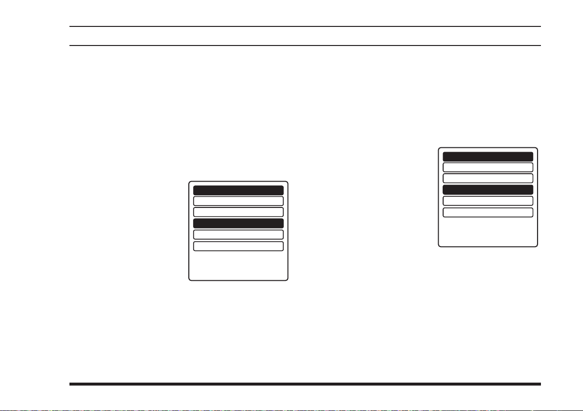
scannIng operatIon
The
FTA-750/FTA-550
nels automatically in the COMM (COM band), MR, and
WX modes. It pauses on signals encountered, so you can
talk to the station(s) on that frequency if you like.
allow you to scan active chan-
Scanning All Channels
1. Set the radio to the COMM mode.
2.
Press the
3. Select
[►]
4. Select
screen by pressing the
[◄]
then press the
key.
The scanning starts and the display returns to the
COMM mode screen.
[
MENU
“
FUNC
key, and then press the
“
SCAN
[►]
or
]
key to display the
” on the screen by pressing the
[
ENT
” on the
key, and
[
ENT
SCAN MEM
DUAL WATCH
]
SCAN
SPLIT
LOGGER
MENU
]
key.
FUNCTION
screen
[◄]
OFF
OFF
OFF
OFF
OFF
.
or
The scanner searches signals from the lower fre-
quency to higher.
When the scanner encounters a signal, the scanning
pauses and the radio remains on that channel until
the signal disappears, and the frequency indication
on the display blinks.
After the signal disappears, the scanning resumes.
To stop the scanning,
press the
or select “
in the
FUNCTION
Next time the scanning is activated, the search will
start from the frequency at which the scanning was
stopped last time.
PTT
SCAN
switch,
” again
menu.
FUNCTION
SCAN MEM
DUAL WATCH
SCAN
SPLIT
LOGGER
OFF
OFF
ON
OFF
OFF
FTA-750/FTA-550 OperATing MAnuAl
55
Page 58

scannIng operatIon
Note:
When you enable the alarm function at reception of the
weather alert signal via the
SETUP mode, the last weather channel will be watched
as the every second frequency during a scan.
Example: when the last weather channel is
162.4 MHz, the radio scans in the following order.
108.000 → 162.400 → 108.025 → 162.400 →
108.050 → 162.400 ...
The frequency of the last weather channel, however,
will not be displayed until the scanner encounters the
weather alert signal.
COMM SETUP
menu in the
Scanning the Specied Channels
Among the memory and weather channels, you may
scan only those on which you want to see if a signal
exists.
Marking the channels
1. Set the radio to the MR or WX mode and tune to the
channel that you want to be scanned.
2.
Press the
3. Select
[►]
key, and then press the
[
“
FUNC
MENU
]
key to display the
” on the screen by pressing the
[
ENT
]
key.
MENU
screen
[◄]
.
or
4. Select
The current channel is
5. Repeat steps 1 to 4 above to mark other channels as
“
SCAN MEM
the screen by pressing
[◄]
the
then press the
key.
marked to be scanned
and the “
which indicates that the
channel is the target
of scanning, will appear at the right side of
the channel frequency
when the display returns to the MR or WX
mode screen.
well.
or
[►]
MEM
” on
key, and
[
ENT
” icon,
FUNCTION
SCAN MEM
DUAL WATCH
]
SCAN
SPLIT
LOGGER
BUSY
MR
133.800
Los Angeles
VOL
132.400 Las Vega
OFF
OFF
OFF
OFF
OFF
MEM
56
FTA-750/FTA-550 OperATing MAnuAl
Page 59

scannIng operatIon
Scanning the marked channels
Set the radio to the MR or WX mode, then perform
steps 2 to 4 of the section “Scanning All Channels”
in the previous page.
The scanning starts and the display returns to the
MR or WX mode screen.
The
Note:
When you enable the alarm function at reception of the
weather alert signal via the
SETUP mode, the last weather channel will be watched
as the every second channel during a scan.
The frequency of the last weather channel, however,
will not be displayed until the scanner encounters the
weather alert signal.
FTA-750/FTA-550
as that when scanning all channels described in the
previous page, except that it searches a signal on the
marked frequencies only.
Example: when the last weather channel is WX03, the
radio scans in the following order.
MEM001 → WX03 → MEM002 → WX03 →
MEM003 → WX03 ...
operate in the same way
COMM SETUP
menu in the
FTA-750/FTA-550 OperATing MAnuAl
57
Page 60
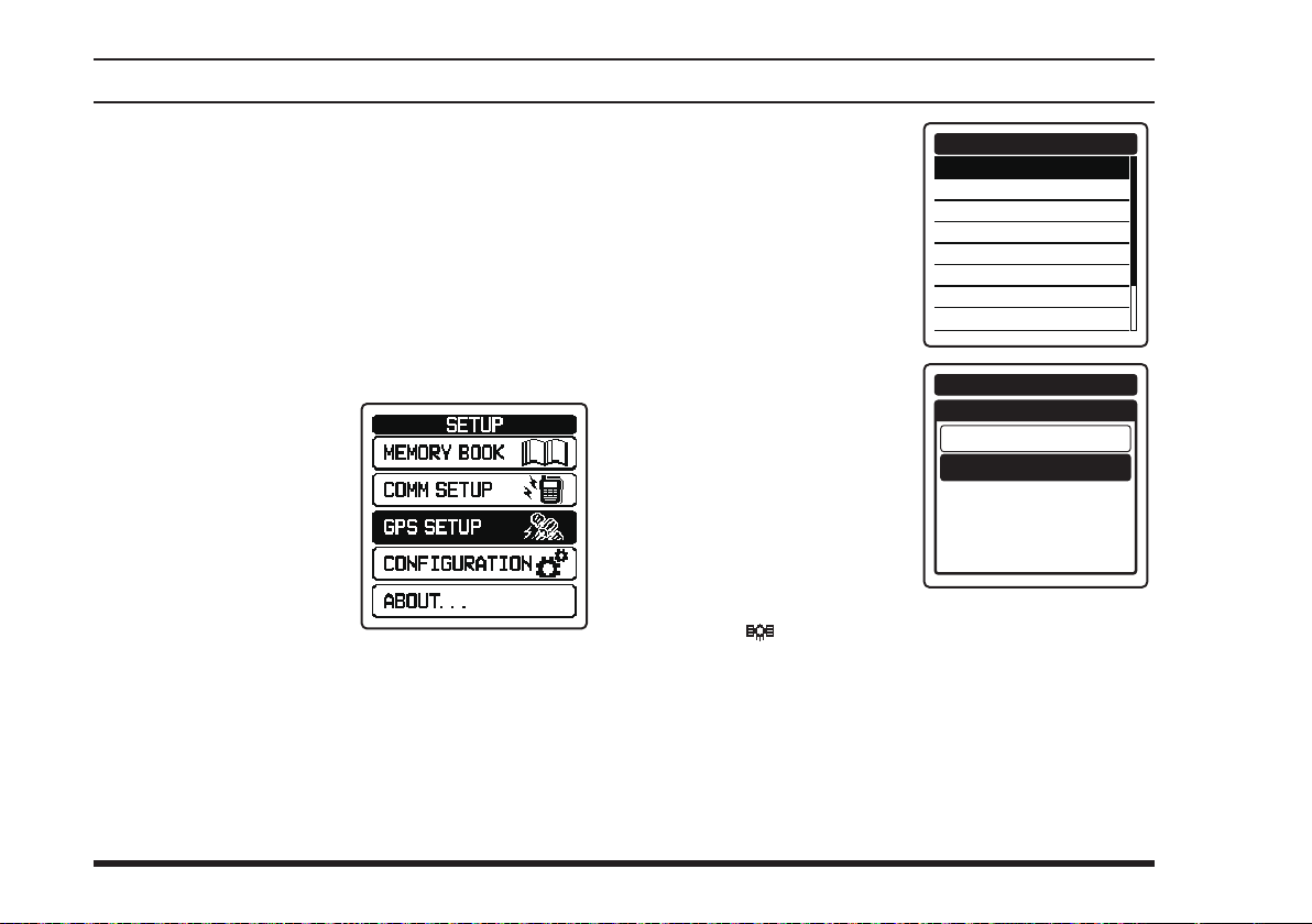
gps FunctIon (Fta-750 only)
The
FTA-750
receive and display the position information at all
times. The position information of your own as well as
recieved stations can be memorized and utilized later for
navigation.
has an internal GPS reception unit to
Activating the GPS Unit
1.
Press the
2. Select
or
3. Select
the screen by pressing
the
then press the
key.
[
MENU
“
SETUP
[►]
key, and then press the
“
GPS SETUP
[◄]
or
]
key to display the
” on the screen by pressing the
” on
[►]
key, and
[
]
ENT
[
ENT
MENU
]
key.
58
screen
[◄]
4. Select
.
5. Select
The GPS unit is set to
The “ ” icon will appear on the top of the display
Notes:
The GPS unit is set to ON by default.
To reduce the power consumption, you are recom-
“
GPS ON/OFF
on the screen by pressing the
key, and then press the
[
ENT
screen by pressing the
[◄]
then press the
key.
ON and the display
will return to the
SETUP
when returning to the screen of the COMM, MR, or
other operation mode.
mended to turn the GPS unit OFF if unnecessary.
[◄]
]
key.
“ON” on the
[►]
or
key, and
menu.
or
[►]
[
ENT
GPS
”
GPS SETUP
GPS ON/OFF
POWER SAVE
RECALL GPS + F
LOCATION FORMAT
UTC/LOCAL
TIME OFFSET
TIME FORMAT
UNIT OF MEASURE
GPS SETUP
GPS ON/OFF
]
OFF
ON
FTA-750/FTA-550 OperATing MAnuAl
Page 61

gps FunctIon (Fta-750 only)
Displaying the Position Information
You can choose the way to display the position
information from three types; numerical, compass, and
numerical with GPS status.
Notes:
You may change the unit of displayed measure-
ments via the SETUP mode.
You may set the time area and offset via the SETUP
mode.
The position information will be displayed with
the screen type you have selected last time before
switching the operation mode or turning off the radio.
Numerical display
or
[
MENU
“
GPS
[►]
1.
Press the
2. Select
screen by pressing the
[◄]
then press the
key.
]
key to display the
” on the
key, and
[
]
ENT
MENU
screen
.
3. Select
The latitude and lon-
Note:
The power save operation of the GPS unit is disabled
while displaying the position information.
“
GPS INFO
the screen by pressing
[◄]
the
then press the
key.
gitude of your current
position, COG (course
over ground), SOG
(speed over ground),
altitude, and the date
will be displayed below
the VOL meter on the
screen.
or
[►]
” on
key, and
[
ENT
MARK POSITION
]
GPS INFO
COMPASS
GPS STATUS
BUSY
MR
FLG
133.800
KLAX-ATIS
VOL
LAT/LON
23°56.890N
123°56.890W
COG
095
°
DATE
Oct/25 09:56
GPS
SOGKT
095
MEM
ALT
M
0956.8
AM
FTA-750/FTA-550 OperATing MAnuAl
59
Page 62

gps FunctIon (Fta-750 only)
Compass display
1.
Press the
2. Select
[►]
3. Select
[
MENU
“
GPS
key, and then press the
“
COMPASS
the screen by pressing
[◄]
the
or
then press the
key.
The compass with
your traveling course
up, COG (course over
ground), SOG (speed
over ground), altitude,
and the date will be displayed below the VOL
meter on the screen.
Note:
The power save operation of the GPS unit is disabled
while displaying the position information.
]
key to display the
MENU
” on the screen by pressing the
[
]
key.
ENT
[►]
” on
key, and
[
ENT
]
GPS
MARK POSITION
GPS INFO
COMPASS
GPS STATUS
BUSY
MR
133.800
FLG
KLAX-ATIS
VOL
screen
[◄]
MEM
COG T
000
°
SOGkph
360
ALTft
10000
Oct/25
09:56
AM
.
or
Numerical display with GPS status
1.
Press the
2. Select
[►]
3. Select
[
“
GPS
key, and then press the
“
GPS STATUS
on the screen by pressing the
[◄]
key, and then press the
[
]
key.
ENT
The latitude and lon-
gitude of your current
position, a radar scope
showing the position of
captured GPS satellites,
bars indicating the signal strength of captured
GPS satellites, and the
date will be displayed
below the VOL meter
on the screen.
]
MENU
key to display the
MENU
” on the screen by pressing the
[
]
key.
ENT
or
[►]
”
GPS
MARK POSITION
GPS INFO
COMPASS
GPS STATUS
BUSY
MR
133.800
FLG
KLAX-ATIS
VOL
STATUS
SEARCH
DATE
LAT/LON
23°56.890N
123°56.890W
Oct/25 09:56AM
screen
[◄]
.
or
60
FTA-750/FTA-550 OperATing MAnuAl
Page 63
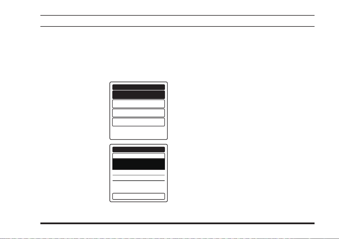
gps FunctIon (Fta-750 only)
Memorizing the Position Information
You can save your position information at a certain point
of time in the memory book of the radio.
1.
Press the
2. Select
[►]
3. Select
TION
pressing the
key, and then press the
[
ENT
[
MENU
“
GPS
key, and then press the
“
MARK POSI-
” on the screen by
]
key.
]
key to display the
” on the screen by pressing the
[
ENT
]
key.
MENU
GPS
[◄]
or
[►]
MARK POSITION
GPS STATUS
GPS INFO
COMPASS
screen
[◄]
.
or
If you need no change to the items on the form,
[
press the
be stored into the memory and the display returns
to the screen displayed before entering the menu
mode.
If you want to change or input either of the items
in the form, press the
item, then press the
Input letters and/or numerics with the keypad or
the
DIAL
Press the
have been done to store them into the memory.
Press the
puts.
]
key. The position information will
SAVE
[◄]
[
ENT
selector knob, then press the
[
]
key after all the inputs or changes
SAVE
[
BACK
]
key to cancel the changes or in-
or
]
key.
[►]
key to select the
[
ENT
]
key.
The
MARK POSITION
form appears on the
display, with the name
(tag), frequency, group
tag, and current position information already
lled.
GPS
MARK POSITION
Name:
001MARK________
Freq.:133.800
Flag:No
LAT 33˚56.325
LON 118˚24.225
MHz
N
W
Press [SAVE] key
FTA-750/FTA-550 OperATing MAnuAl
61
Page 64
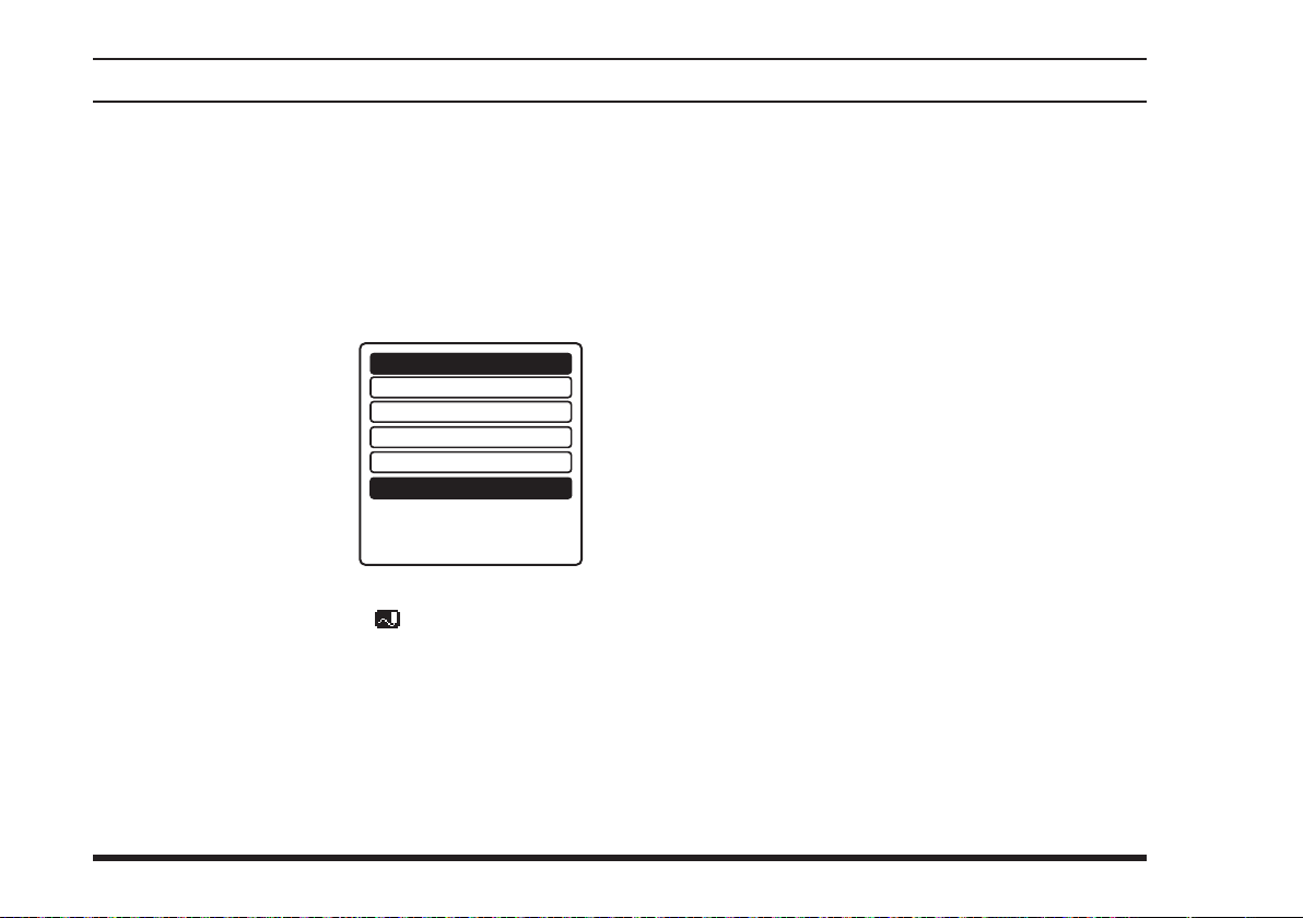
gps FunctIon (Fta-750 only)
Recording the Position Information
The
FTA-750
that allows you to record your location at a regular
interval.
1.
Press the
2. Select
[►]
3. Select
the screen by pressing
the
then press the
key.
The recording starts and the display returns to the
previous screen with the “ ” icon on the top of
the display.
You may change the interval time of recording via
the SETUP mode.
includes a logger for position information
[
MENU
“
FUNC
key, and then press the
“
LOGGER
[◄]
or
]
key to display the
” on the screen by pressing the
[
ENT
” on
[►]
key, and
[
ENT
SCAN MEM
DUAL WATCH
]
SCAN
SPLIT
LOGGER
MENU
]
key.
FUNCTION
screen
[◄]
OFF
OFF
OFF
OFF
OFF
.
or
Notes:
The power save operation of the GPS unit is dis-
abled while the logger is activated.
To utilize the records, connect the
and take the log data from the radio by using the PC
Programming Software
be downloaded through the YAESU website).
YCE01
FTA-750
(the
to a PC
YCE01
may
Logger operation alert
When the memory for log data becomes full, three
beeps will sound and a warning message will be
displayed.
Afterwards the logger does not operate until the log
data in the memory are erased.
When the logger cannot record for some reasons,
three beeps will sound and a warning message will
be displayed.
Afterwards the logger does not operate anymore.
An error message will be displayed when the radio
cannot erase the log data in the memory during the
operation following the alert of memory full (see
above) or in the SETUP mode (see Page 76).
62
FTA-750/FTA-550 OperATing MAnuAl
Page 65
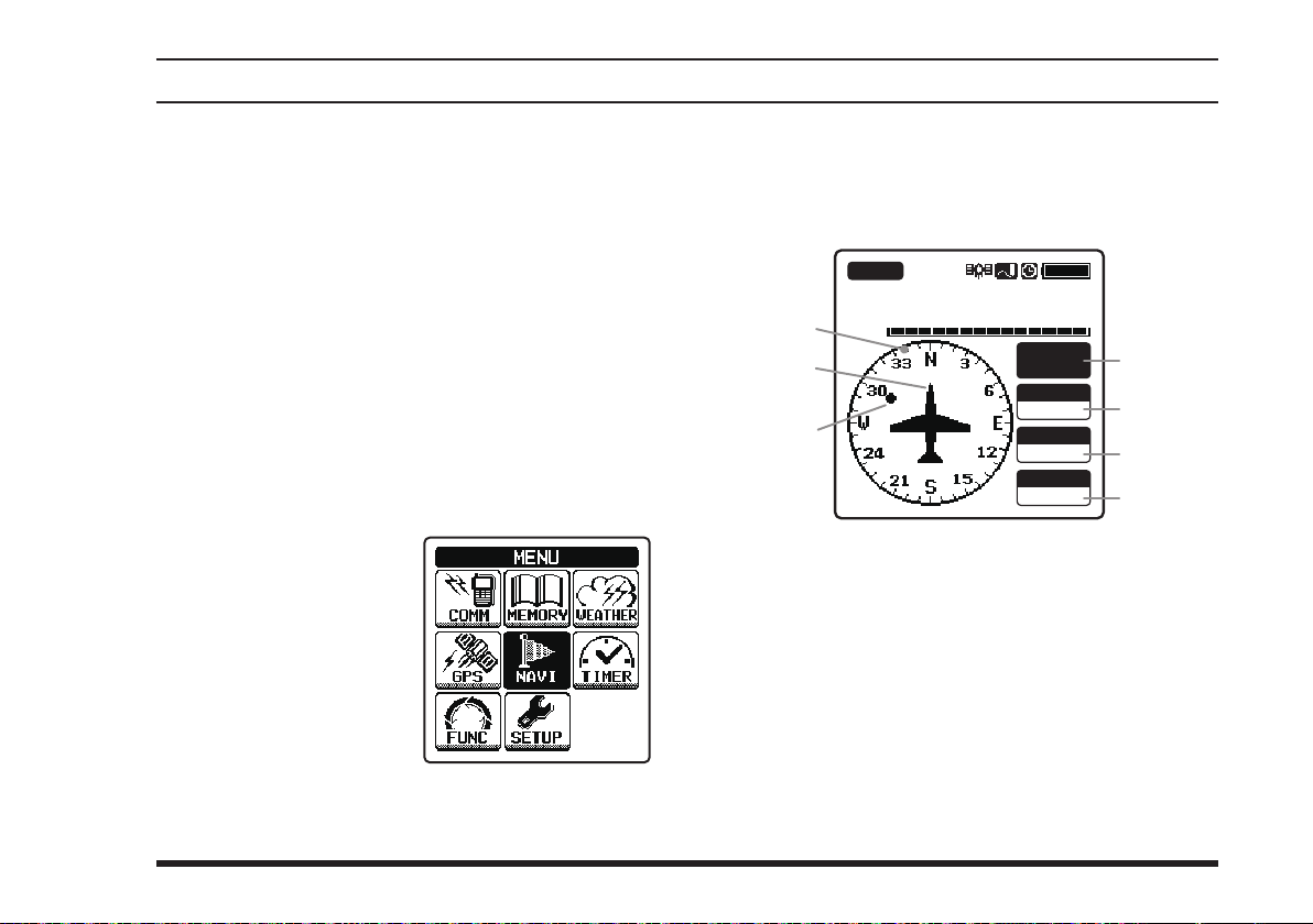
WaypoInt naVIgatIon (Fta-750 only)
The navigation feature of the
compass that helps you to gure out the destination and
your traveling direction at a glance.
The destination can be selected from the memory
channels and the list of points you have selected
previously, or can be directly specied.
Notes:
Be sure that the internal GPS unit has been activated
before using the navigation.
The navigation does not work when insufficient
number of GPS satellites are captured to obtain your
position.
FTA-750
is presented in a
Entering the Navigation (NAVI) Mode
Select
MENU
ing the
key, and then press the
[
“
NAVI
screen by press-
[◄]
]
key.
ENT
” on the
[►]
or
The compass screen including the destination you
have selected last time will be displayed if you did
not reach there before switching the operation mode
or turning off the radio.
BUSY
MR
ALL
VOL
Compass rose
Course indicator
Destination indicator
Tag name of the destination
DST (distance)
COG (course over ground)
SOG (speed over ground)
The compass rose rotates to display the travelling
course up.
133.800
KLAX-ATIS
KLAX
DSTkm
10
COG T
000
SOGkph
360
°
FTA-750/FTA-550 OperATing MAnuAl
63
Page 66

WaypoInt naVIgatIon (Fta-750 only)
Setting the Destination
When the radio enters the NAVI mode for the rst time,
or if you have reached the destination during the NAVI
mode last time, the
selecting “
NAVI
” on the
menu will be displayed after
NAVI
screen.
MENU
Selecting from the memory
1.
Select
on the
pressing the
key, and then press the
[
ENT
2. Select a group that the
desired station is assigned by pressing the
[◄]
then press the
key.
]
key.
or
NAVI
[►]
“
MEMORY
menu by
[◄]
or
key, and
[
ENT
[►]
”
NAVI
HISTORY
MEMORY
MANUAL
NAVI
MEMORY
ALL
FLAG
]
3. Select a station from the
station list of the group
]
key.
[◄]
or
by pressing the
[►]
key, and then press
[
the
ENT
The information of the
selected station will appear with the reversed
“
the bottom.
” displayed at
GOTO
ALL
Los Angeles
McCarran
Lakeland
KLGB
KLAK
KSAN-VOR
MIAMI
Name:
KLAK
Freq.:127.600
Flag:No
LAT 33˚56.325
LON 118˚24.225
NAVI
MEMORY
NAVI
GOTO
[
4. Press the
The compass screen will be displayed.
ENT
]
key.
Selecting from the history
Select
“
and set the desired station in the same way as steps
3 and 4 above.
History
” on the
menu, and then select
NAVI
MHz
N
W
64
FTA-750/FTA-550 OperATing MAnuAl
Page 67
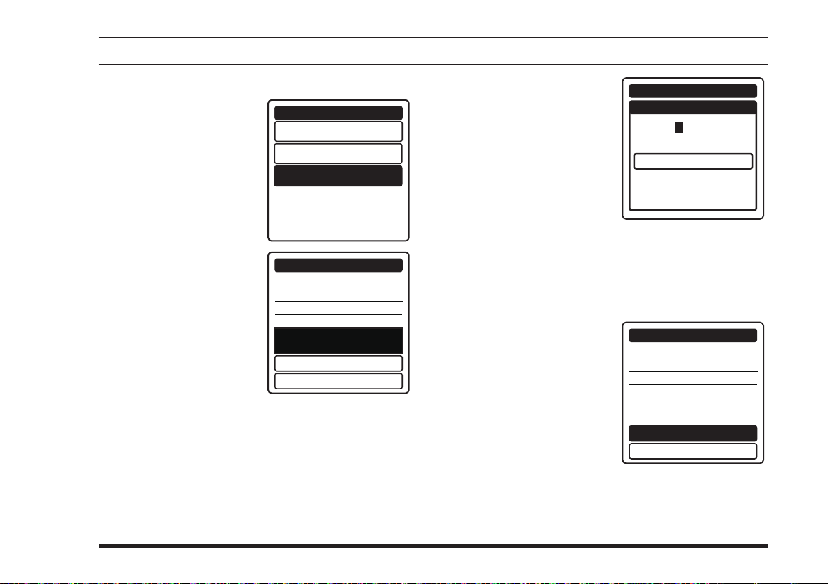
WaypoInt naVIgatIon (Fta-750 only)
Specifying the position directly
1.
Select
on the
pressing the
key, and then press the
[
ENT
2. Select the “
“
LON
the
then press the
key.
“
MANUAL
menu by
NAVI
[◄]
or
]
key.
” and
LAT
” eld by pressing
[◄]
[►]
or
key, and
[
ENT
[►]
”
HISTORY
Name:
001WPT
Freq.:---.---
]
Flag:No
LAT --˚--.--LON ---˚--.---
SAVE AND GOTO
NAVI
MEMORY
MANUAL
NAVI
_________
MHz
-
-
GOTO
3. Input numerics and letters with the keypad or
the
then press the
key.
The cursor will move
to the next digit of the
position information.
4. Repeat step 3 to input all digits of the position information.
If you want to correct a mistake, press the
[►]
change, then perform step 3 again.
5. Select “
pressing the
key, and then press the
[
ENT
The input information
will appear with the
reversed “
played at the bottom.
6. Press the
The compass screen will be displayed.
selector knob,
DIAL
[
ENT
key to move the cursor to the digit you want to
[◄]
or
” b y
[►]
FINISH
]
LAT
LON
Name:
001WPT
]
key.
Freq.:---.--Flag:No
LAT 33˚56.325
LON 118˚24.225
” dis-
GOTO
[
]
key.
ENT
NAVI
POSITION
--˚--.---
---˚--.---
-
-
FINISH
[◄]
NAVI
_________
MHz
N
W
GOTO
SAVE AND GOTO
or
FTA-750/FTA-550 OperATing MAnuAl
65
Page 68

WaypoInt naVIgatIon (Fta-750 only)
You may store the input information to the memory
of the radio by selecting
step 6 above.
You may give a custum tag name to the input
information and
step 6, in the same way as steps 2 to 5.
assign it to a desired group before
“
SAVE AND GOTO
” before
66
FTA-750/FTA-550 OperATing MAnuAl
Page 69
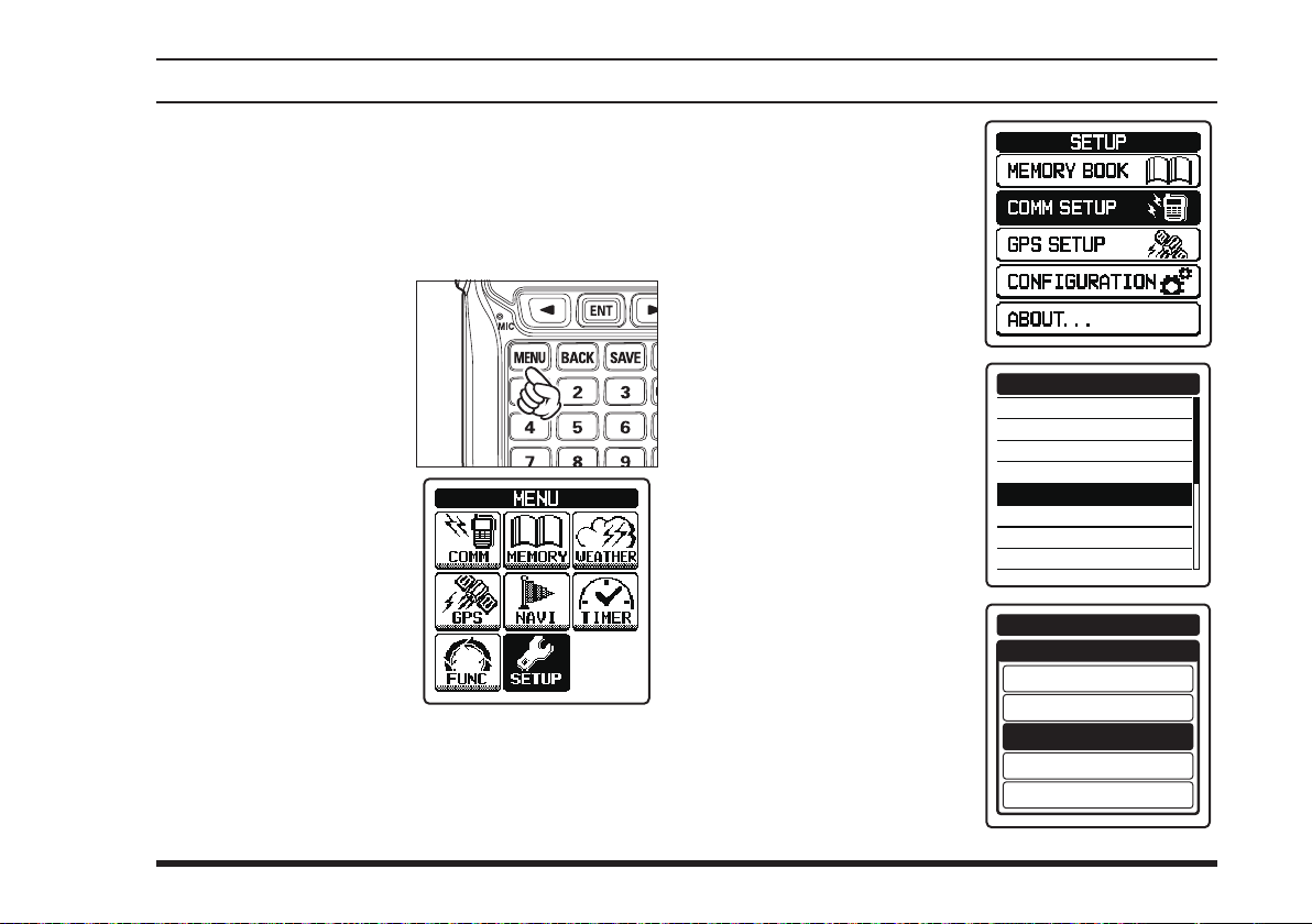
setup mode
Note:
We do not recommend that any of the default settings
be changed until you are thoroughly familiar with the
operation of the
FTA-750/FTA-550
.
Basic Operation
1. Press the
to display the
screen
2.
Select
MENU
ing the
key, and then press the
[
ENT
[
MENU
.
“
SETUP
screen by press-
[◄]
]
key.
]
key
MENU
” on the
[►]
or
3.
Select
the item on the
menu by press-
SETUP
ing the
key, and then press the
[
ENT
4. S
elect
wish to view and/or
change the settings by
pressing the
key, and then press the
[
ENT
5. Enter or select settings
on the screen dedicated
to each item, and then
press the
determine the new settings.
[◄]
]
key.
the item you
]
key.
[
ENT
[◄]
or
or
]
key to
[►]
[►]
COMM SETUP
EMERGENCY CALL
ANL
WEATHER ALERT
PTT SCAN STOP
SCAN RESUME
SCAN STOP TYPE
DUAL WATCH FREQ.
SPLIT FREQUENCY
COMM SETUP
SCAN RESUME
0sec
1sec
2sec
3sec
5sec
FTA-750/FTA-550 OperATing MAnuAl
67
Page 70
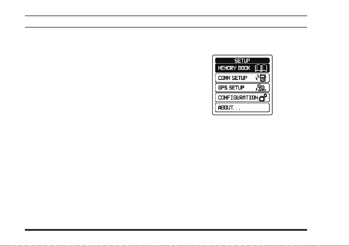
setup mode
Menu items
MEMORY BOOK
You may store the frequencies or positions with a
tag name to the memory of the radio, and maintain
the stored entries.
COMM SETUP
You may set and adjust the operations of the radio
in the COMM mode.
GPS SETUP
You may set and adjust the operations of the radio
in the GPS mode.
CONFIGURATION
You may set and adjust the various conditions of the
radio.
ABOUT...
You may confirm the version of the software cur-
rently operating on the radio.
(FTA-750 only)
Maintenance of the Memory
See Pages 52 to 54 for details.
68
FTA-750/FTA-550 OperATing MAnuAl
Page 71

setup mode
Setting of the COMM Mode Operation
Turning on/off the emergency call
You may enable or disable the quick access to the
121.500 MHz emergency frequency (see also Page 21).
COMM SETUP
EMERGENCY CALL
ANL
WEATHER ALERT
PTT SCAN STOP
SCAN RESUME
SCAN STOP TYPE
DUAL WATCH FREQ.
SPLIT FREQUENCY
COMM SETUP
EMERGENCY CALL
OFF
ON
Turning on/off the automatic noise limiter
See Page 48 for details.
FTA-750/FTA-550 OperATing MAnuAl
Turning on/off the weather alert
You may enable or disable the alarm function when receiving the weather alert signal (see also Page 36).
COMM SETUP
EMERGENCY CALL
ANL
WEATHER ALERT
PTT SCAN STOP
SCAN RESUME
SCAN STOP TYPE
DUAL WATCH FREQ.
SPLIT FREQUENCY
COMM SETUP
WEATHER ALERT
OFF
ON
Turning on/off the scan stop with the PTT
You may lock out the
tion (see also Page 55).
COMM SETUP
EMERGENCY CALL
ANL
WEATHER ALERT
PTT SCAN STOP
SCAN RESUME
SCAN STOP TYPE
DUAL WATCH FREQ.
SPLIT FREQUENCY
switch during the scan opera-
PTT
COMM SETUP
PTT SCAN STOP
OFF
ON
69
Page 72

setup mode
Setting the scan resume time
You may select a waiting time till the resuming of scan
after the encountered signal disappears (see also Page
55).
COMM SETUP
EMERGENCY CALL
ANL
WEATHER ALERT
PTT SCAN STOP
SCAN RESUME
SCAN STOP TYPE
DUAL WATCH FREQ.
SPLIT FREQUENCY
COMM SETUP
SCAN RESUME
0sec
1sec
2sec
3sec
5sec
Setting the operation after stopping a scan
You may select either of the operations below when encountering a signal during a scan (see also Page 55).
BUSY STOP
5sec STOP
10sec STOP
COMM SETUP
EMERGENCY CALL
ANL
WEATHER ALERT
PTT SCAN STOP
SCAN RESUME
SCAN STOP TYPE
DUAL WATCH FREQ.
SPLIT FREQUENCY
... Stays at the frequency and will not
resume the scan
... Stays at the frequency for 5 seconds
and then resume the scan
... Stays at the frequency for 10 sec-
onds and then resume the scan
COMM SETUP
SCAN STOP TYPE
BUSY STOP
5sec STOP
10sec STOP
70
FTA-750/FTA-550 OperATing MAnuAl
Page 73
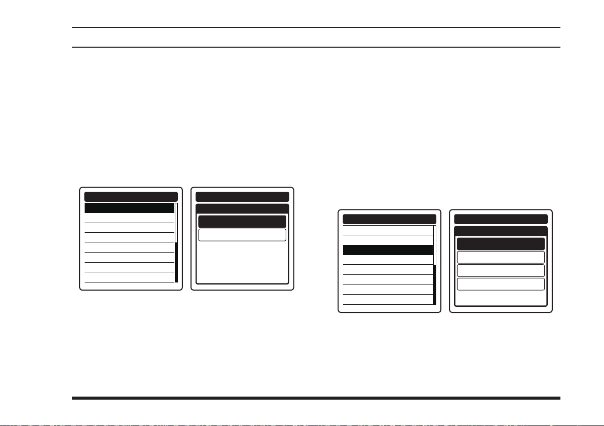
setup mode
Setting the polled frequency for dual watch
See Page 37 for details.
Setting the transmit frequency during the
NAV band reception
See Page 33 for details.
Setting the frequency step for tuning
You may select the frequency rate for one click of the
selector knob (see also Page 19).
DIAL
COMM SETUP
FREQUENCY STEP
TX TOT
AF PITCH CONT.
MIC SELECT
SIDE TONE
VOX
VOX LEVEL
VOX DELAY
COMM SETUP
FREQUENCY STEP
25kHz
8.33kHz
Setting the time-out timer for transmission
See Page 43 for details.
Setting the audio lter of the receiver
You may select the operation of the audio lter from the
following 4 types.
NORMAL
LOW CUT
HIGH CUT
HIGH AND LOW CUT
FREQUENCY STEP
TX TOT
AF PITCH CONT.
MIC SELECT
SIDE TONE
VOX
VOX LEVEL
VOX DELAY
... No ltering
... Cuts off the lower range of sound
... Cuts off the higher range of sound
... Cuts off the higher and
lower ranges of sound
COMM SETUP
COMM SETUP
AF PITCH CONT
HIGH AND LOW CUT
NORMAL
LOW CUT
HIGH CUT
FTA-750/FTA-550 OperATing MAnuAl
71
Page 74

setup mode
Setting the microphone conguration
See Page 44 for details.
Setting the side tone operation
See Page 45 for details.
Turning on/off the VOX operation
See Page 44 for details.
Setting the sensitivity of the VOX system
See Page 45 for details.
Setting the sensing time of the VOX system
See Page 45 for details.
Setting of the GPS Mode Operation
(FTA-750 Only)
Turning on/off the internal GPS unit
See Page 58 for details.
72
FTA-750/FTA-550 OperATing MAnuAl
Page 75
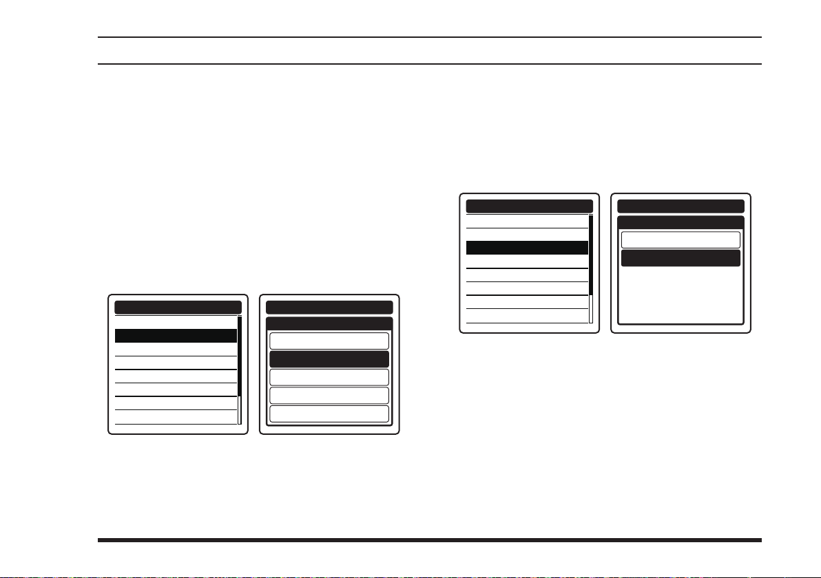
setup mode
Setting the power save operation of the
internal GPS unit
You may select an interval time of periodical operation
of the GPS unit to reduce battery consumption (see also
Pages 59, 60, 62).
... Operates all the time
OFF
... Sleeps until a GPS signal is received or the
AUTO
radio enters the GPS or NAVI mode
... Sleeps for 3 sec after 3 sec operation
50%
... Sleeps for 9 sec after 3 sec operation
75%
... Sleeps for 27 sec after 3 sec operation
90%
GPS SETUP
GPS ON/OFF
POWER SAVE
RECALL GPS + F
LOCATION FORMAT
UTC/LOCAL
TIME OFFSET
TIME FORMAT
UNIT OF MEASURE
GPS SETUP
POWER SAVE
OFF
AUTO
50%
75%
90%
Turning on/off the recall of the frequency
during the NAVI mode
You may tune the radio to the frequency of the
marked position set as the destination of the waypoint
navigation, if the position has been saved with its
frequency.
GPS SETUP
GPS ON/OFF
POWER SAVE
RECALL GPS + F
LOCATION FORMAT
UTC/LOCAL
TIME OFFSET
TIME FORMAT
UNIT OF MEASURE
GPS SETUP
RECALL GPS + F
OFF
ON
FTA-750/FTA-550 OperATing MAnuAl
73
Page 76
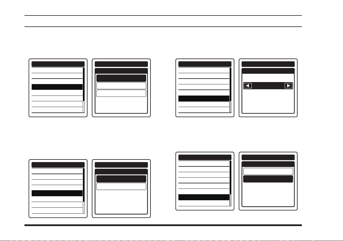
setup mode
Setting the notation format of location
You may select the coordinate system for position information to be shown on the display (see also Page 59).
GPS SETUP
GPS ON/OFF
POWER SAVE
RECALL GPS + F
LOCATION FORMAT
UTC/LOCAL
TIME OFFSET
TIME FORMAT
UNIT OF MEASURE
GPS SETUP
LOCATION FORMAT
ddd˚mm.mmm
ddd˚mm.mm
ddd˚mm.ss
Setting the time area
You may select either of the UTC (universal time coordinated) time or local time to be shown on the display (see
also Page 59).
GPS SETUP
GPS ON/OFF
POWER SAVE
RECALL GPS + F
LOCATION FORMAT
UTC/LOCAL
TIME OFFSET
TIME FORMAT
UNIT OF MEASURE
GPS SETUP
UTC/LOCAL
UTC
LOCAL
Setting the time offset
You must set the time offset of your current area when
using the local time (see also Page 59).
GPS SETUP
GPS ON/OFF
POWER SAVE
RECALL GPS + F
LOCATION FORMAT
UTC/LOCAL
TIME OFFSET
TIME FORMAT
UNIT OF MEASURE
GPS SETUP
TIME OFFSET
+09:00
Setting the notation format of time
You may select either of the 24-hour or 12-hour notation
of time to be shown on the display (see also Page 59).
GPS SETUP
GPS ON/OFF
POWER SAVE
RECALL GPS + F
LOCATION FORMAT
UTC/LOCAL
TIME OFFSET
TIME FORMAT
UNIT OF MEASURE
GPS SETUP
TIME FORMAT
24hour
12hour
74
FTA-750/FTA-550 OperATing MAnuAl
Page 77
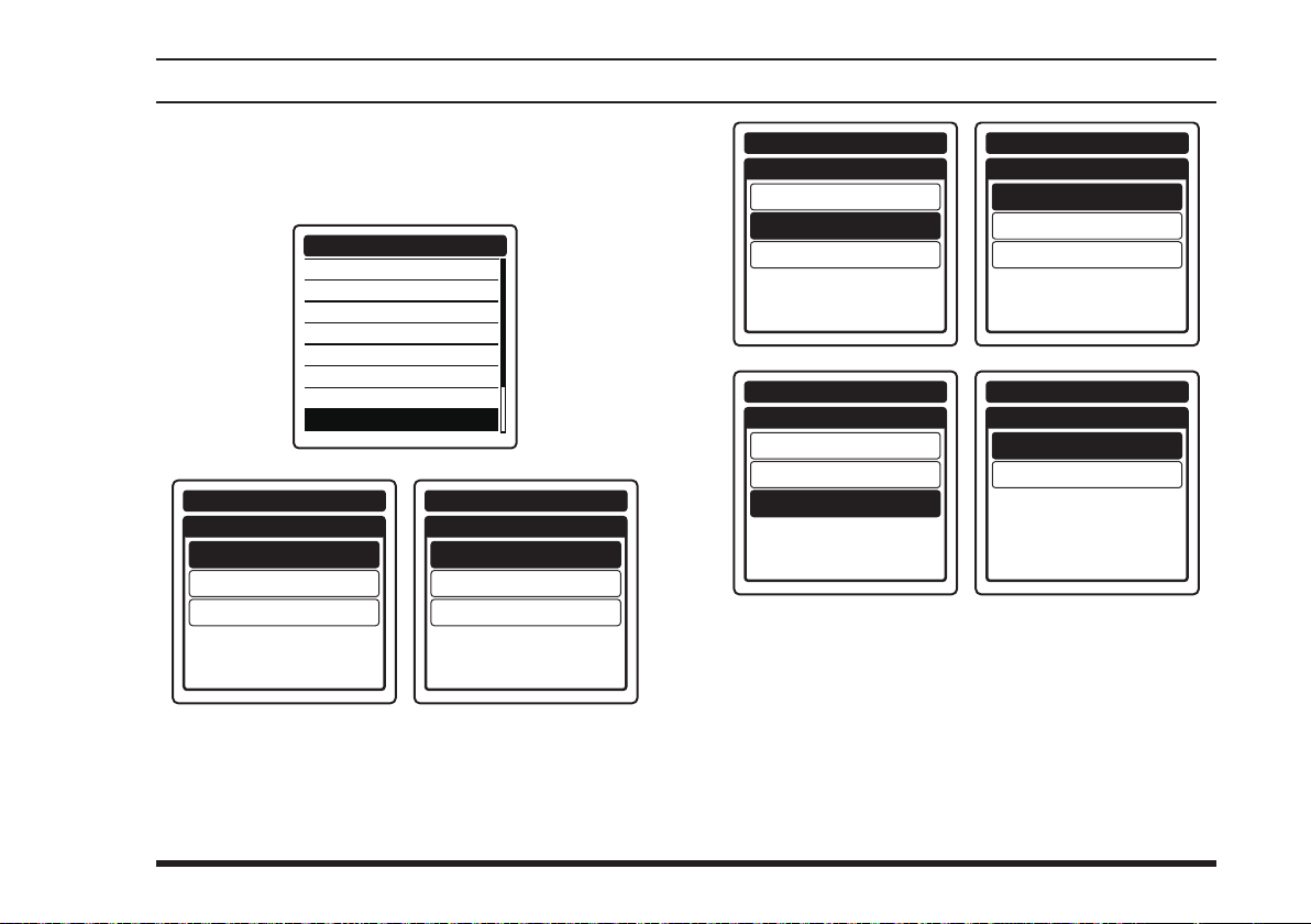
setup mode
Setting the unit of measurement
You may select the unit of speed, distance, and altitude
to be shown on the display (see also Page 59).
GPS SETUP
GPS ON/OFF
POWER SAVE
RECALL GPS + F
LOCATION FORMAT
UTC/LOCAL
TIME OFFSET
TIME FORMAT
UNIT OF MEASURE
GPS SETUP
UNIT OF MEASURE
SPEED
DISTANCE
ALTITUDE
kts
sm
ft
GPS SETUP
SPEED
knots
mile/h
km/h
GPS SETUP
UNIT OF MEASURE
SPEED
DISTANCE
ALTITUDE
kts
sm
ft
GPS SETUP
UNIT OF MEASURE
SPEED
DISTANCE
ALTITUDE
kts
sm
ft
GPS SETUP
DISTANCE
statute mile
nautical mile
GPS SETUP
ALTITUDE
km
feet
meter
FTA-750/FTA-550 OperATing MAnuAl
75
Page 78

setup mode
Turning on/off the pinning
You may enable or disable the update of the position
information when you have stayed at a location for a
certain period of time.
GPS SETUP
POWER SAVE
RECALL GPS + F
LOCATION FORMAT
UTC/LOCAL
TIME OFFSET
TIME FORMAT
UNIT OF MEASURE
PINNING
GPS SETUP
PINNING
OFF
ON
Turning on/off the differential GPS feature
You may use the SBAS (satellite-based augmentation
system) while obtaining the position information.
GPS SETUP
RECALL GPS + F
LOCATION FORMAT
UTC/LOCAL
TIME OFFSET
TIME FORMAT
UNIT OF MEASURE
PINNING
D-GPS
GPS SETUP
D-GPS
OFF
ON
Setting the interval time of logging
You may select a time rate for recording of the position
information obtained from the GPS (see also Page 62).
GPS SETUP
LOCATION FORMAT
UTC/LOCAL
TIME OFFSET
TIME FORMAT
UNIT OF MEASURE
PINNING
D-GPS
LOGGER INTERVAL
GPS SETUP
LOGGER INTERVAL
1sec
3sec
5sec
10sec
30sec
Erasing the log
You may delete the records of the position information
obtained from the GPS (see also Page 62).
GPS SETUP
UTC/LOCAL
TIME OFFSET
TIME FORMAT
UNIT OF MEASURE
PINNING
D-GPS
LOGGER INTERVAL
LOG ERASE
GPS SETUP
LOG ERASE
OK?
CANCEL
76
FTA-750/FTA-550 OperATing MAnuAl
Page 79

setup mode
Setting of the Operation and
Conguration of the Radio
Setting the brightness of the display
You may adjust the dimmer in 5 levels.
CONFIGURATION
DIMMER
LAMP
CONTRAST
KEY BEEP
TIMER ALARM
BATTERY SAVE
LOCK SELECT
RESET
CONFIGURATION
DIMMER
3
Setting the lamp of the display
You may select the operation of the display lighting
from the following 4 types.
... No lighting at any time
OFF
CONTINUOUS
KEY ON
EXT PO/KEY
CONFIGURATION
DIMMER
LAMP
CONTRAST
KEY BEEP
TIMER ALARM
BATTERY SAVE
LOCK SELECT
RESET
... Lights at all time
... Lights for 5 seconds only when any key
is pressed
... Lights for 5 seconds only when any
key is pressed, or lights at all time
when the power is supplied through
the
EXT DC
jack
CONFIGURATION
CONTINUOUS
EXT PO/KEY
LAMP
OFF
KEY ON
FTA-750/FTA-550 OperATing MAnuAl
77
Page 80
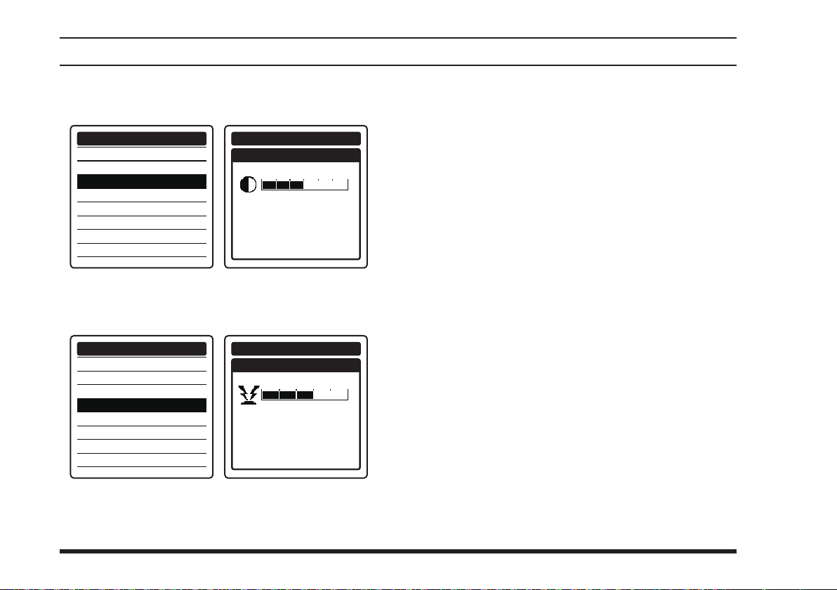
setup mode
Setting the contrast of the display
You may adjust the contrast in 30 levels.
CONFIGURATION
DIMMER
LAMP
CONTRAST
KEY BEEP
TIMER ALARM
BATTERY SAVE
LOCK SELECT
RESET
CONFIGURATION
CONTRAST
15
Setting the loudness of key beeps
You may adjust the loudness in 5 levels.
CONFIGURATION
DIMMER
LAMP
CONTRAST
KEY BEEP
TIMER ALARM
BATTERY SAVE
LOCK SELECT
RESET
CONFIGURATION
KEY BEEP
3
Turning on/off the timer alarm
See Page 42 for details.
Setting the power save operation
See Page 43 for details.
Setting the lockout conguration
See Page 46 for details.
78
FTA-750/FTA-550 OperATing MAnuAl
Page 81
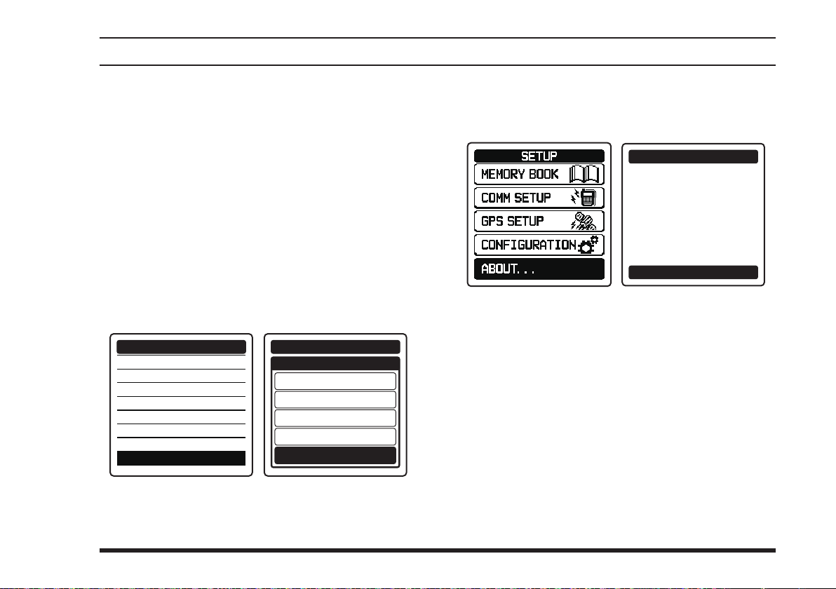
setup mode
Resetting the radio
You may initialize the memories and settings of the
menu categories independently or all at once (see also
Pages 25 and 26).
FUNCTION
MEMORY
COMM & GPS
CONFIGURATION
FACTORY
CONFIGURATION
DIMMER
LAMP
CONTRAST
KEY BEEP
TIMER ALARM
BATTERY SAVE
LOCK SELECT
RESET
... Initializes the on/off settings in the
FUNCTION
... Clears the entries in the memory
... Initializes the settings in the
COMM SETUP
menus
... Resets the radio to factory default
menu
and
GPS SETUP
... Initializes the settings in the
CONFIGURATION
menu
CONFIGURATION
RESET
FUNCTION
MEMORY
COMM & GPS
CONFIGURATION
FACTORY
About the Radio
You may conrm the version of the software currently
operating on the radio.
ABOUT...
Software Version
Ver:00.**
Date:Oct 25.20**
Yaesu Musen co., ltd
OK
FTA-750/FTA-550 OperATing MAnuAl
79
Page 82
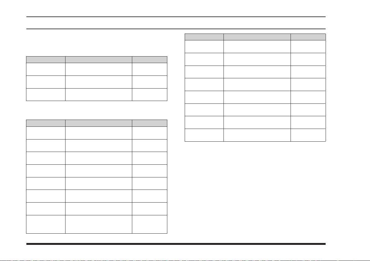
setup mode
Summary of the SETUP Menu
MEMORY BOOK
Item Description Default Value
ADD Adding new channels or
EDIT Editing the stored informa-
DELETE Deleting the stored channel
destinations
tion
or destination
COMM SETUP
Item Description Default Value
EMERGENCY
CALL
ANL Turning on/off the automatic
WEATHER
ALERT
PTT SCAN
STOP
SCAN
RESUME
SCAN STOP
TYPE
DUAL WATCH
FREQ.
SPLIT
FREQUENCY
Turning on/off the emergency call
noise limiter
Turning on/off the weather
alert
Turning on/off the scan stop
with the PTT
Setting the scan resume
time
Setting the operation after
stopping a scan
Setting the polled frequency
for dual watch
Setting the transmit
frequency during the NAV
band reception
−
−
−
ON
OFF
OFF
ON
3 sec
BUSY STOP
−
−
Item Description Default Value
FREQUENCY
STEP
TX TOT Setting the time-out timer
AF PITCH
CONT.
MIC SELECT Setting the microphone
SIDE TONE Setting the side tone opera-
VOX Turning on/off the VOX
VOX LEVEL Setting the sensitivity of the
VOX DELAY Setting the sensing time of
Setting the frequency step
for tuning
for transmission
Setting the audio lter of the
receiver
conguration
tion
operation
VOX system
the VOX system
25 kHz
5 min
NORMAL
INT MIC
OFF
OFF
LEVEL 2
1.5 sec
80
FTA-750/FTA-550 OperATing MAnuAl
Page 83
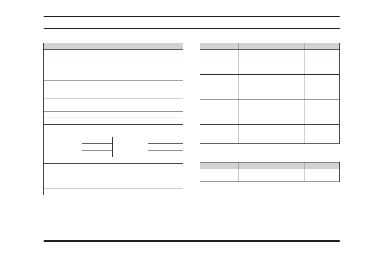
setup mode
GPS SETUP (FTA-750 only)
Item Description Default Value
GPS ON/OFF Turning on/off the internal
POWER SAVE Setting the power save
RECALL GPS
+ F
LOCATION
FORMAT
UTC/LOCAL Setting the time area UTC
TIME OFFSET Setting the time offset 0:00
TIME FORMAT Setting the notation format
UNIT OF
MEASURE
PINNING Turning on/off the pinning OFF
D-GPS Turning on/off the differen-
LOGGER
INTERVAL
LOG ERASE Erasing the log −
GPS unit
operation of the internal
GPS unit
Turning on/off the recall of
the frequency during the
NAVI mode
Setting the notation format
of location
of time
SPEED Setting
DISTANCE nautical mile
ALTITUDE feet
tial GPS feature
Setting the interval time of
logging
the unit of
measurement
AUTO
dddºmm.
mmm
24 hour
knots
5 sec
ON
OFF
ON
CONFIGURATION
Item Description Default Value
DIMMER Setting the brightness of the
LAMP Setting the lamp of the
CONTRAST Setting the contrast of the
KEY BEEP Setting the loudness of key
TIMER ALARM Turning on/off the timer
BATTERY
SAVER
LOCK
SELECT
RESET Resetting the radio −
display
display
display
beeps
alarm
Setting the power save
operation
Setting the lockout congu-
ration
EXT PO/KEY
ALL LOCK
ABOUT...
Item Description Default Value
− Conrming the version of
the software
5
15
3
ON
50%
−
FTA-750/FTA-550 OperATing MAnuAl
81
Page 84

specIFIcatIons
General
Frequency Range: TX: 118.000 to 136.975 MHz
RX: 108.000 to 136.975 MHz (NAV and COM bands)
161.650 to 163.275 MHz (Weather Channels)
329.150 to 335.000 MHz (Glide slope; FTA-750 only)
Channel Spacing: 25 kHz/8.33 kHz
Emission Type: TX: AM
RX: AM & FM (FM: for receiving the Weather Channels)
Supply Voltage: 6.0 to 9.5 VDC
Current Consumption (approx.): 300 µA (power off),
70 mA (battery saver on, saver ratio 50%)
80 mA (squelch on),
300 mA (receive),
0.9 A (transmit 1.5 W Carrier)
Temperature Range: +14 ºF to + 140 ºF (–10 ºC to +60 ºC)
Case Size (W x H x D): 2.4 x 5.2 x 1.3 inches (62 x 133 x 34 mm) with SBR-12LI
Weight (approx.): 14.5 oz (410 g) with SBR-12LI, antenna and belt clip
Receiver
Circuit Type: Double-conversion superheterodyne
IFs: 47.25 MHz & 450 kHz
Sensitivity: Better than 0.8 µV (for 6 dB S/N with 1 kHz, 30 % modulation)
Selectivity: >8 kHz/–6 dB
Adjacent CH. Selectivity: <25 kHz/–60 dB
AF Output (@7.4 V): 0.8 W @ 16 Ohms, 10 % THD
82
FTA-750/FTA-550 OperATing MAnuAl
Page 85

specIFIcatIons
Transmitter
Power Output (@ 7.4 V): 5.0 W (PEP), 1.5 W (Carrier Power)
Frequency Stability: Better than ±1 ppm (+14 ºF to + 140 ºF [–10 ºC to +60 ºC])
Modulation System: Low Level Amplitude Modulation
Spurious Emission: >70 dB below carrier
Int. Microphone Type: Condenser
Ext. Mic. Impedance: 150 Ohms
GPS Unit (FTA-750 only)
Receiver Channels 66 Channels
Sensitivity Less than –147 dBm
Time to First Fix 1 minute typical (@ Cold Start)
5 seconds typical (@ Hot Start)
Geodetic Datum WGS84
Specications are subject to change without notice or obligation.
FTA-750/FTA-550 OperATing MAnuAl
83
Page 86

trouBleshootIng For headset connectIon
Question Answer
When connecting the
cable between the radio and a headset, the “
icon appears on the display and the radio cannot
be operated.
Can I purchase the optional PTT Switch from
Yaesu?
Will my headset work with this radio? The
SCU-15
headset adapter
3.5mm plug
Speaker
PTT
Microphone
Ground
This happens when the plug on the
inserted into the
”
TX
To make proper contacts within the radio, the plug must be pushed all the way
in the
Contact your Aviation dealer for details on purchasing an aftermarket Push-ToTalk switch.
however to be concretely sure to check with the headset manufacturer providing
the wiring shown below. Please confirm the connections and connector sizes are
correct.
SCU-15
Headset specication requirements for SCU-15
Earphone (speaker) impedance: 8 Ω or above
Microphone impedance: 150 Ω ±20%
PTT pressed: Ground
PTT not pressed: Open
84
MIC/SP
SCU-15
SCU-15
MIC/SP
jack and be fixed with the two screws.
headset adapter cable is made to operate with most headsets;
jack.
Speaker
PJ-055
(accepts 0.25” phone plug)
Microphone
PJ-068
(accepts 0.206” phone plug)
headset adapter cable is simply
FTA-750/FTA-550 OperATing MAnuAl
Page 87

note
FTA-750/FTA-550 OperATing MAnuAl
85
Page 88

note
86
FTA-750/FTA-550 OperATing MAnuAl
Page 89
key again to
key.
]
key.
key.
[ ]
[
[SAVE]
Press the
the frequency to be stored with
the DIAL selector knob or the key-
pad.
name or attribute, press and hold
Saving the Frequency to Memory
1. In the COMM mode screen, set
(Cut Here)
Quick Reference
2.
3. To save the data with a specific
FTA-750
FTA-550
FTA-750/FTA-550 OperATing MAnuAl
the MENU screen.
2. Press the [◄] or [►] key to se-
key.
[ENT]
the
2. Press the [◄] or [►] key to select
lect “WEATHER”, then press the
the desired channel from the list,
the [SAVE] key.
Receiving the Weather Channels
1. Press the [MENU] key to display
press
YAESU MUSEN CO., LTD.
Quick Reference Card
Recalling the Previous Frequencies
1. In the COMM mode screen,
[ENT]
Press the
[ENT] key.
the desired channel from the list.
Press and hold the
3. Press the [◄] or [►] key to select
4.
Locking the Dial and Keys
key.
[ENT]
press the
then
the MENU screen.
Recalling the Memory Channels
1. Press the [MENU] key to display
2. Press the [◄] or [►] key to select
unlock.
Press and hold the
“MEMORY”, then press the [ENT]
key.
Selecting the Operation Mode
the [◄] or [►] key to se-
Press
3.
the MENU screen.
the mode, then press the [ENT] key.
before pressing the [MENU] key,
press the [BACK] key several
1. Press the [MENU] key to display
2. Press the [◄] or [►] key to select
3. To return to the screen displayed
key.
[ENT]
press the
the [◄] or [►] key to select
Press
lect a group including the desired
channel from the list, then press
the [ENT] key.
4. After switching to the MR mode
the desired channel from the list,
screen,
87
5.
times.
key.
[ENT]
press the
then
Page 90

press the [BACK] key several
times.
OBS Setting on the VOR CDI Screen
1. Press the [MENU] key to display
key.
2. Press the [◄] or [►] key to select
“SETUP”, then press the [ENT]
GPS Activation
the MENU screen.
2. Press the appropriate keys on
the keypad to enter numbers, or
rotate the DIAL selector knob to
select a degree.
3. Select “GPS SETUP”, then press
4. Select “GPS ON/OFF”, then press
5. Select “ON”, then press the [ENT]
6. To return to the screen displayed
the [ENT] key.
the [ENT] key.
key.
before pressing the [MENU] key,
1. In the VOR CDI on the NAV band
screen,
to select “OBS”.
press
4. Press the [BACK] key to delete
5.
clear all the characters in the in-
put eld.
one character.
Press and hold the
[BACK] key to
3.
Press
the cursor.
the [◄] or [►] key to move
(FTA-750 only)
Entering and Editing Characters
2. Press the appropriate keys on the
the character.
keypad to enter numbers.
1. Rotate the DIAL selector knob to
select alphabets and numbers,
then press the [ENT] key to set
3.
Press the
reversed.
[ENT]
key with “GOTO”
4.
press the [ENT] key.
the desired destination from the
list, then
Press
the [◄] or [►] key to select
press the
[ENT]
key.
3. Press the [◄] or [►] key to select
“HISTORY” or “MEMORY”, then
the [◄] or [►] key
Waypoint Navigation
1. Press the [MENU] key to display
2. Press the [◄] or [►] key to select
the MENU screen.
“NAVI”, then press the [ENT] key.
(FTA-750 only)
88
FTA-750/FTA-550 OperATing MAnuAl
Page 91
Under Industry Canada regulations, this radio transmitter may only operate using an antenna of a type
and maximum (or lesser) gain approved for the transmitter by Industry Canada. To reduce potential radio interference to other users, the antenna type and its gain should be so chosen that the equivalent
isotropically radiated power (e.i.r.p.) is not more than that necessary for successful communication.
Conformément à la réglementation d’Industrie Canada, le présent émetteur radio peut fonctionner
avec une antenne d’un type et d’un gain maximal (ou inférieur) approuvé pour l’émetteur par Industrie Canada. Dans le but de réduire les risques de brouillage radioélectrique à l’intention des autres
utilisateurs, il faut choisir le type d’antenne et son gain de sorte que la puissance isotrope rayonnée
quivalente (p.i.r.e.) ne dépassepas l’intensité nécessaire à l’établissement d’une communication satisfaisante.
This radio transmitter (identify the device by certication number, or model number if Category II) has
been approved by Industry Canada to operate with the antenna types listed below with the maximum
permissible gain and required antenna impedance for each antenna type indicated. Antenna types not
included in this list, having a gain greater than the maximum gain indicated for that type, are strictly
prohibited for use with this device.
Le présent émetteur radio (identier le dispositif par son numéro de certication ou son numéro de
modèle s’il fait partie du matériel de catégorie I) a été approuvé par Industrie Canada pour fonctionner
avec les types d’antenne énumérés ci-dessous et ayant un gain admissible maximal et l’impédance
requise pour chaque type d’antenne. Les types d’antenne non inclus dans cette liste, ou dont le gain
est supérieur au gain maximal indiqué, sont strictement interdits pour l’exploitation de l’émetteur.
Part 15.21: Changes or modications to this device not expressly approved by YAESU MUSEN could
void the user’s authorization to operate this device.
Page 92

YAESU MUSEN CO., LTD.
Tennozu Parkside Building
2-5-8 Higashi-Shinagawa, Shinagawa-ku, Tokyo
140-0002 Japan
YAESU USA
6125 Phyllis Drive, Cypress, CA 90630, U.S.A.
YAESU UK
Unit 12, Sun Valley Business Park, Winnall Close
Winchester, Hampshire, SO23 0LB, U.K.
YAESU HK
Unit 2002, 20/F, 9 Chong Yip Street,
Kwun Tong, Kowloon, Hong Kong
Copyright 2014
YAESU MUSEN CO., LTD.
All rights reserved.
No portion of this manual may be
reproduced without the permission of
YAESU MUSEN CO., LTD.
Printed in Japan
1402L-0O
 Loading...