

Page 1
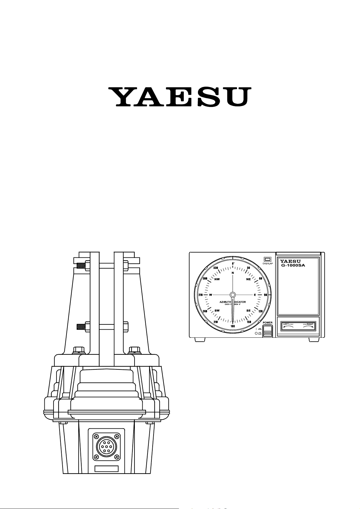
G-800SA
G-1000SA
Antenna Rotator & Controller
User Manual
VERTEX STANDARD CO., LTD.
4-8-8 Nakameguro, Meguro-Ku, Tokyo 153-8644, Japan
VERTEX STANDARD
US Headquarters
10900 Walker Street, Cypress, CA 90630, U.S.A.
YAESU EUROPE B.V.
P.O. Box 75525, 1118 ZN Schiphol, The Netherlands
YAESU UK LTD.
Unit 12, Sun Valley Business Park, Winnall Close
Winchester, Hampshire, SO23 0LB, U.K.
VERTEX STANDARD HK LTD.
Unit 5, 20/F., Seaview Centre, 139-141 Hoi Bun Road,
Kwun Tong, Kowloon, Hong Kong
Page 2

IMPORTANT !
The installation of a rotatable antenna on a tower system is a dangerous and potentially life-threatening task, if due care
is not taken.
A tower must never be installed in a position where it could fall across power distribution cables in the event of a
catastrophic tower failure during a windstorm or earthquake.
The control cable attached to this rotator could, in the event of a nearby or direct lightning strike, carry lethal voltages
down the cable and into your home. Yaesu strongly recommends the installation of suitable lightning arrestors on all
control cables and coaxial lead-in cables from your antenna installation. See your dealer for details of available lightning-protection devices.
If an electrical storm should be reported in your area, quickly unplug the control cable from the rear of the rotator’s
controller box, and disconnect the AC cable from the wall outlet. Disconnect the coaxial cable(s) from the antenna(s) as
well. Do this only if the lightning is not in your immediate area, as you could be killed instantly if lightning should
strike while you are holding a cable.
If you have any doubts about your ability to install this rotator safely, enlist the services of a professional antenna
installation company.
Page 3
G-800SA
G-1000SA
Heavy-Duty Antenna Rotator & Controller
The Yaesu G-800SA and G-1000SA are designed to
rotate large tower-mounted amateur and professional antenna arrays under remote control from the station operating position. The clamshell rotator design utilizes 98
7/16-inch dual-stacked circumferential ball bearings to
distribute load over the full diameter of the housing. This
design minimizes stress and wear, and practically eliminates the possibility of destructive water entry: there is
no shaft hole in the top of the housing.
Instead of the usual AC motor drive used in older rotator
designs, the G-800SA and G-1000SA use a DC motor,
obviating the need for a large starting capacitor with its
potential for failure exposed to outside temperature variations. The factory-lubricated rotator unit is housed in
melamine resin-coated die-cast aluminum, intended to
provide maintenance-free operation under all climatic
conditions. A mast alignment gauge on the rotator housing simplifies accurate mechanical alignment during installation.
The handsome desktop controller matches the design of
modern transceivers, providing 360° radial indication of
actual antenna bearing azimuth.
The operator may select the stopper heading (the bearing through which the rotator cannot be turned) most
convenient for his location and operation, allowing full
rotation through north, south or both, if desired. In any
case, 90° overlapping rotation allows rotation through
the selected stopper heading (450° total rotation).
The rotator is intended for mounting inside a support
tower (not supplied), at least 1 meter from the top, with
an optional (Yaesu model GS-065 or GS-680U) thrust
bearing above.
The G-800SA and G-1000SA includes one mast clamp
and related hardware, plus plug connectors for both the
rotator and controller. A six conductor cable of the necessary length must be supplied by the owner.
Please read this manual through carefully before installing the rotator, to acquaint yourself with the procedures
that will be required, and to ensure that you have all necessary items for your installation.
G-800SA/G-1000SA User Manual Page 1
Page 4
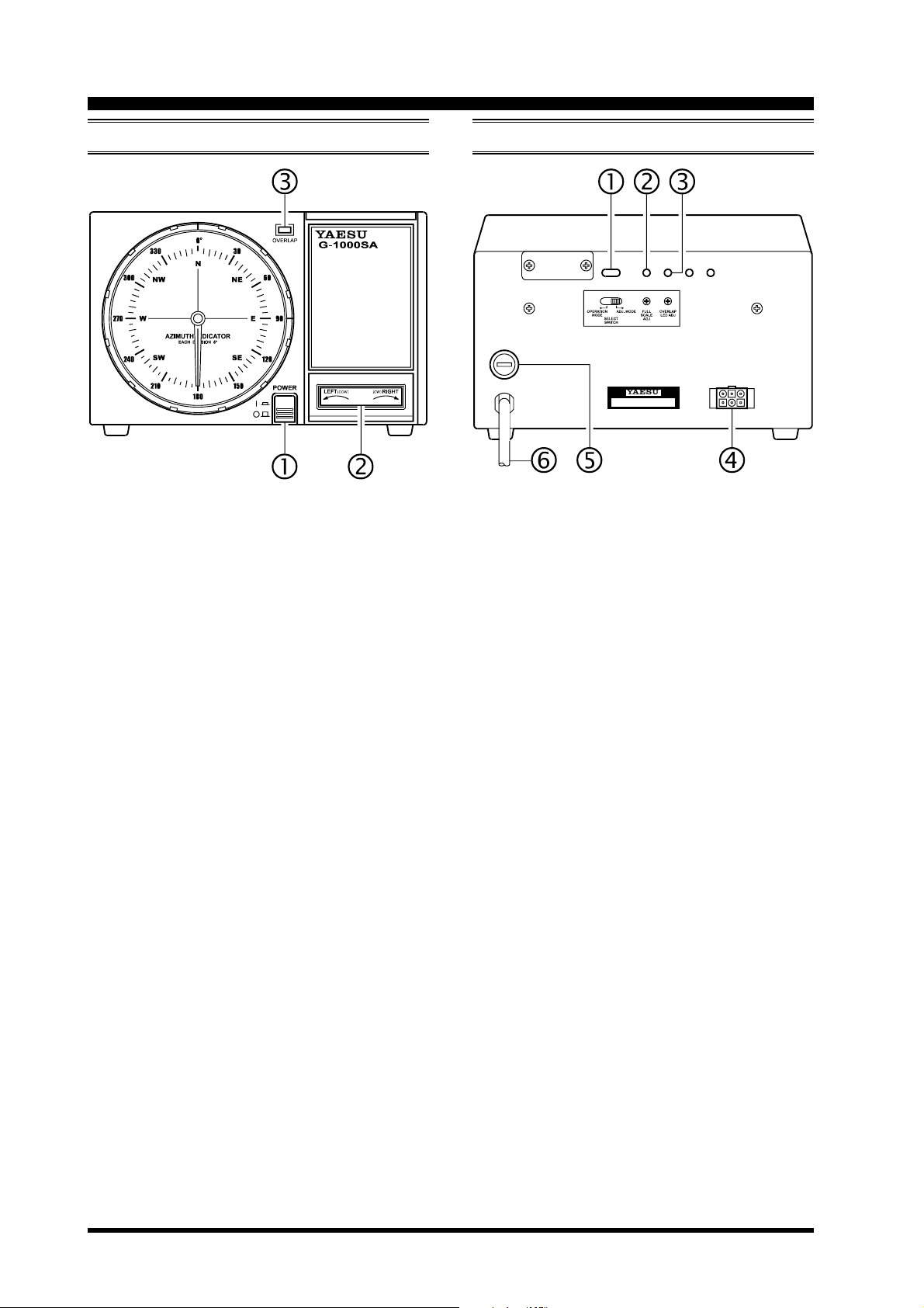
Controller Switches & Controls
FRONT PANEL REAR PANEL
POWER Switch
Press this switch to turn the controller on to rotate
the antenna. Turn it off when the rotator is not in
use.
LEFT/RIGHT Seesaw Switch
Press the LEFT side of this switch to rotate the antenna counter-clockwise (CCW). Press the RIGHT
side to rotate the antenna clockwise (CW).
OVERLAP Indicator
This red LED glows when the antenna is rotated
beyond about 180° (to 270°) from its original installation direction (180°). Check this indicator before rotating the antenna clockwise, and turn the
antenna counter-clockwise to the desired position if
the indicator is on.
SELECT SWITCH
Set this switch to the “ADJ. MODE” position while
calibrating the internal adjustments of the controller. During normal operation, however, set this switch
to the “OPERATION MODE” position.
FULL SCALE ADJ Potentiometer
This control calibrates the maximum rotation angle
(range) of the azimuth indicating needle to match
the maximum angle of the rotator.
OVERLAP LED ADJ Potentiometer
This control calibrates the OVERLAP Indicator to
match the azimuth indicating needle.
Rotator Control Cable Jack
The supplied control cable from the rotator connects
to this 6-pin jack.
FUSE Holder
This holder requires a 2-A fuse for 117V AC. If the
fuse is blown, replace only with a fuse of the same
rating.
AC Cable
Connect this cable to the 117V AC wall outlet.
G-800SA/G-1000SA User ManualPage 2
Page 5
Antenna Considerations
The types of antennas that can be attached to this product differ widely, depending on the installation method, local
terrain, and the maximum expected wind speeds at your location.
The following pages described typical antennas which are acceptable for installation with the G-800SA or G-1000SA.
The discussion below assumes maximum wind speeds of 30 meters per second, and it is recommended that you include
a safety margin of at least 40% to account for higher wind gusts or other factors which might potentially cause
damage to your installation.
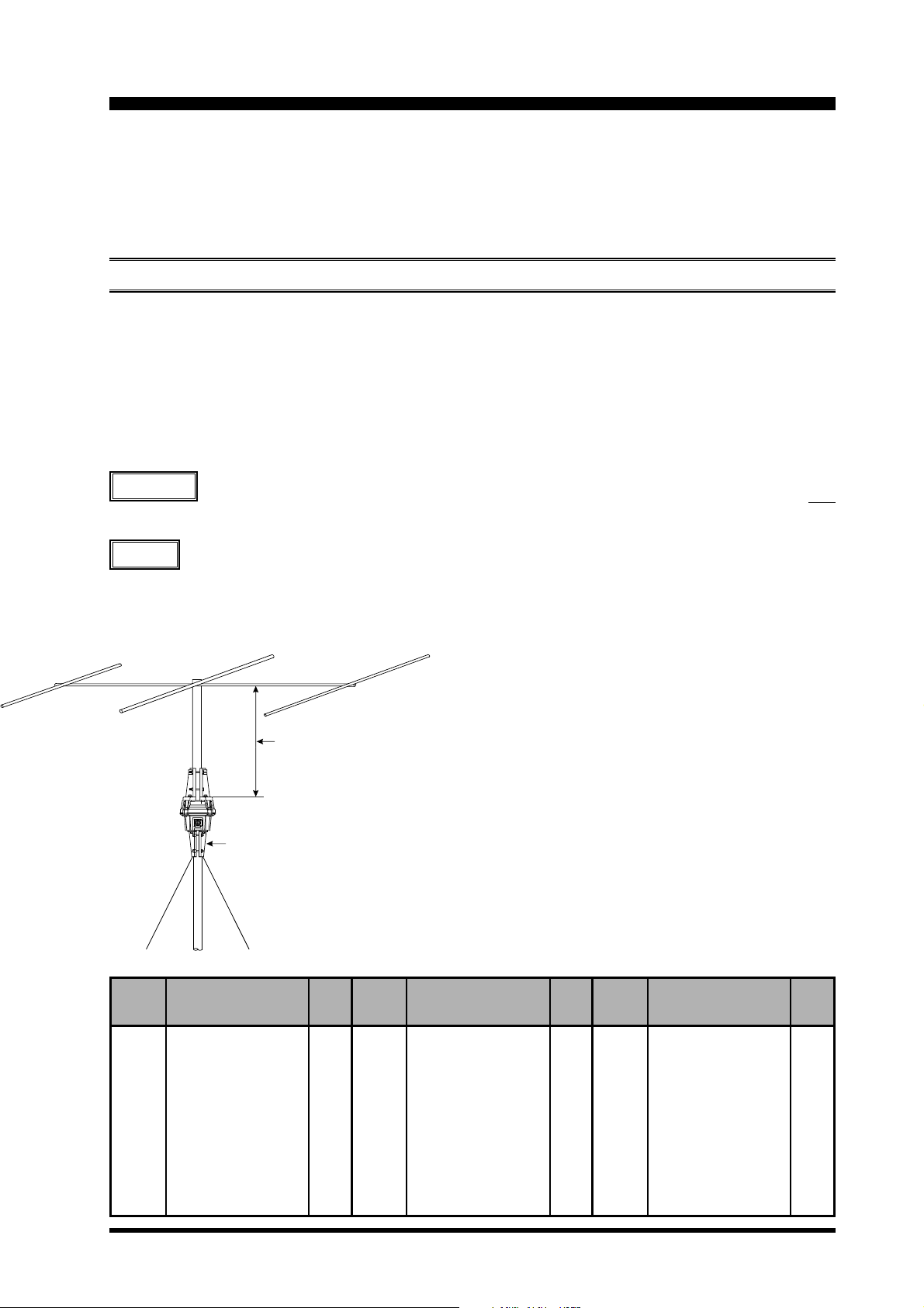
POLE-MOUNTED ANTENNAS
Mounting of the rotator on a pole or mast results in a significant de-rating of the size of the antenna which can be
mounted, due to the tremendous bending forces applied to the rotator’s clamps. For pole mounting, the product of
multiplying the [Antenna Wind Load Area (in m2)] by the [Height of the Antenna Mast (in m)] must be less than 0.45.
See below Table and Figure.
[
Antenna Wind Load Area
] x [
Height of Antenna Mast] = 0.45
Refer to the antenna manufacturer’s specification sheet for determining the weight and the surface area of the proposed
antenna.
Example
For a 14 MHz 3-element Yagi of Surface area of 0.7 m2 (see Table 1), the above specifications for pole
mounting will be met if the antenna is mounted on a mast not longer than 0.3 m (0.7 m2 x 0.3 m = 0.21
< 0.27 [0.45 x 40% safety margin].
Advice
We recommend that your antennas/mast should not exceed 60% of the maximum rating, to ensure a
safety margin.
Less than 0.3m
Optional Mast Clamp GC-038
Example of a 14 MHz Band, 3-Element Yagi Antenna
Wind Loading Areas for Common Antennas (Typical)
Band
(MHz)
7
7
7
7
14
14
14
21
21
21
21
21
Elements
2-element
1-element, w/loading coi ls
2-element, w/loading coi ls
3-element, w/loading coi ls
3-element
4-element
5-element
3-element
4-element
5-element
6-element
2-element, Swiss Quad
Area
(m
2.2
0.2
0.6
1.1
0.7
1.2
1.7
0.45
0.6
0.8
1.3
0.3
2
)
Band
(MHz)
28
28
28
28
7/14
7/14
14/21
14/21
21/28
21/28
14/21/28
14/21/28
Elements
3-element
4-element
5-element
2-element, Swiss Quad
3-element, trapped
4-element, trapped
3-element, trapped
4-element, trapped
3-element, trapped
4-element, trapped
3-element, trapped
4-element, trapped
Area
(m
0.3
0.42
0.6
0.3
0.5
0.8
0.4
0.5
0.3
0.4
0.4
0.5
2
)
Band
(MHz)
50
50
50
50
14 4
14 4
14 4
14 4
43 0
43 0
43 0
43 0
Elements
4-element
5-element
6-element
2-element, Swiss Quad
10 - ele me nt
10-elem en t, s tacked
10-element, x 4
10-element, x 4 x 2
12 - ele me nt
12-elem en t, s tacked
12-element, x 4
12-element, x 4 x 2
Area
(m
0.25
0.3
0.37
0.3
0.2
0.44
0.95
2.0
0.06
0.12
0.3
0.6
2
)
G-800SA/G-1000SA User Manual Page 3
Page 6

Antenna Considerations
TOWER-MOUNTED ANTENNAS
In the preferred tower-mounting configuration, the antenna Wind Loading Area must be less than 2 m
2
(G-800SA) or 2.2 m2 (G-1000SA),
and the “K” factor (see below) must not exceed 180 (G-800SA) or
230 (G-1000SA), where K = [Antenna Turning Radius (m)
] x [
Antenna + Mast Weight (kg)].
MODEL
Wind Loading Area
“K” Factor
G-800SA
2
2 m
180
G-1000SA
2
2.2 m
230
Refer to the antenna manufacturer’s specification sheet for determining the turning radius and weight of the antenna.
Example
(1) 14/21/28 MHz 5-element Yagi of Turning Radius 5.6 m, Weight of 26 kg, and Surface area 0.7 m
(2) 50 MHz 5-element Yagi of Turning Radius 2.6 m, Weight of 4.5 kg, and Surface area 0.3 m
In this example, mount the following antennas stacked on a 6 kg mast.
2
2
Note: In such “Christmas Tree” installations, compute the mast weight separately for each antenna, using the relative
heights of the antennas to apportion the mast weight.
The antenna system K factor, then, is the sum of the three antenna K factors:
K1 = K factor of 14/21/28 MHz 5-element Yagi.
K1 = Turning Radius (5.6 m) x Weight (26 kg + 3 kg) = 162.4
Antenna Weight Mast Weight (6 kg/2)
K2 = K factor of 50 MHz 5-element Yagi.
K2 = Turning Radius (2.6 m) x Weight (5 kg + 3 kg) = 20.8
Antenna Weight Mast Weight (6 kg/2)
TOTAL
K
= K1 + K2 = 162.4 + 20.8 = 183.2
The antenna system Wind Loading Area is: 0.7 m2 + 0.3 m2 = 1.0 m
2
The Wind Loading Area (1.0 m2) is within the specifications for the G-800SA and G-1000SA, but the net K factor
(183.2) can only be met by the G-1000SA. Therefore, the above antenna system should only be mounted using a G-
1000SA.
Advice
We recommend that your antennas/mast should not exceed 60% of the maximum rating, to ensure a
safety margin.
Mast Bearing GS-065 (option)
Note: Installation of a Thrust Bearing
such as the GS-065 does not allow the
elimination of the mast weight from the
K-factor calculations above.
Sq. Ft
1
2
3
4
5
6
m
0.093
0.186
0.279
0.372
0.465
0.557
2
Sq. Ft
7
8
9
10
11
12
m
0.650
0.743
0.836
0.929
1.022
1.115
2
Sq. Ft
13
14
15
16
17
18
2
m
1.208
1.301
1.396
1.486
1.579
1.672
Sq. Ft
19
20
21
22
–
–
m
1.765
1.858
1.951
2.044
–
–
2
G-800SA/G-1000SA User ManualPage 4
Page 7

Control Cable Installation
Before installing the rotator, mast, and antenna, prepare the rotator control cable and test rotator system performance on
the ground. Potential alignment, cabling, or other problems can quickly be resolved on the ground; once a rotator is
mounted, however, troubleshooting may require that the tower be climbed and/or the rotator be removed and lowered to
the ground!
CONTROL CABLE PREPARATION
In this Rotator, the user must supply and prepare the
control cable, per the simple instructions below.
The control cable to be used should have six stranded
conductors of at least 0.5 mm (#20 AWG) diameter if
the cable is shorter than 40 m in length (125’); if the
cable is longer than 40 m, use conductors with a diameter of 0.75 mm (#18 AWG) or larger.
1. Disassemble the supplied round plug: slide off the
rubber boot, remove the setscrew from the shell using a small screwdriver, then unscrew the shell from
the plug. Save the setscrew in a safe place until step
10, so you don’t lose it.
2. Slide the rubber boot and the round shell over the
“rotator” end of the cable. Leave enough cable protruding to allow easy dressing the end of the cable.
3. Using special care to avoid nicking the insulation of
the individual wires, strip back 15 mm (about 5/8”)
of the outer jacket of the cable from both ends. Now
strip 5 mm (about 3/16”) of insulation from each
wire, being careful not to nick the conductors.
4. Solder the wires to the round plug pins, noting the
color of the wire and the number associated with
each pin for reference later. Pin 7 of the round con-
nector is not used! Confirm that all solder joints are
firm and cleanly made, as this part of the cable will
be difficult to access once the rotator is installed on
top of the tower. Do not slide the shell onto the connector at this time.
5. Crimp the supplied pin contacts onto the wires on
the opposite end of the cable, per the illustration
below.
6. Referring to your notes of the wire color at each pin
of the round (rotator end) connector, insert the pins
into the rectangular plug at the opposite (controller)
end of the cable. Be sure that each wire from the
round connector is routed to the corresponding pin
number in the rectangular connector (i.e. 1 to 1, 2 to
2, etc.).
7. Temporarily connect the round plug to the rotator,
and the rectangular plug to the controller. Make sure
that the POWER switch on the controller is set to
“OFF,” then plug the controller’s AC cable into your
station’s AC outlet.
8. Set the controller’s POWER switch to “ON.” Verify
that the controller’s pilot lights have become illuminated.
9. Press the LEFT (rotation) side of the seesaw switch,
and confirm that the rotator (when viewed from the
top) and the controller’s needle turn counter-clockwise together. Stop rotation, then press the RIGHT
(rotation) side of the seesaw switch, and confirm that
the rotator and indicator needle turn clockwise. If
rotation does not occur as indicated, turn the
POWER switch “OFF,” and re-check your cable
connections.
10. If the rotator and controller are working as described,
replace the plug shells, setscrew, and rubber boot
(removed in step 1).
15 mm Crimp with a pair of pliers
5 mm
Insert to the fullest extent
Assembly of 6-pin Plastic Connector
Pin No. 7 for the metal connector is not used.
Assembly of 7-pin Metal Connector
G-800SA/G-1000SA User Manual Page 5
Page 8

Mounting the Rotator and Antenna
INDOOR PERFORMANCE CHECK AND ALIGNMENT
1. Temporarily connect the control cable between the
rotator unit and the controller.
2. Set the SELECT SWITCH on the rear panel to the
right (ADJ. MODE) position.
3. Check to be sure that the POWER switch on the
controller is set to “OFF,” then plug the controller’s
AC cable into your station’s AC outlet.
4. Set the controller’s POWER switch to “ON.” The
pilot lamps on the controller should become illuminated, and the meter needle on the controller may
rotate so as to align itself with the current position
of the rotator (remember the two units have not been
aligned with each other).
5. Press the LEFT (rotation) side of the seesaw switch,
and continue to hold it until the rotator reaches the
counter-clockwise position where it automatically
stops (“Left” represents counter-clockwise rotation
when the rotator is viewed from the top).
6. When the rotator has reached the left “stop” position, release the LEFT switch, and check to see if
the controller’s indicator needle is pointing to 180°
(S: South).
If the indicator needle is out of alignment, grasp the
edge of the bezel around the bearing window, turn it
10 ° counter-clockwise, and pull it off. Then, grasp
the needle at its center and pull it straight off, replace the needle to 180° (straight down), and replace
the bezel.
7. Just above the round connector jack on the rotator
unit, you will observe two raised calibration marks
(one each on the “rotating” bell and “fixed” base of
the rotator). These two marks should be directly
aligned with each other. If not, place a small piece
of masking tape on the rotating bell and the fixed
base of the rotator unit, and make a calibration mark
will be used to verify the amount of rotation in the
next step.
8. Press the RIGHT (rotation) side of the seesaw switch,
and continue rotating to the right until the calibration marks (from step 7) are again precisely aligned.
Now check the indicator needle, which should also
have rotated fully 360° so as to be pointing exactly
to 180°.
If the indicator needle is not pointing exactly to 180°,
go to the rear panel of the controller, and use a small
screwdriver to adjust the FULL SCALE ADJ potentiometer (see the drawing to the right) so that the
indicator needle points exactly to 180°.
9. Press the RIGHT switch again, and continue rotation to the right. You should observe the OVER-
LAP LED becoming illuminated as rotation passes
the 180° point.
If the OVERLAP LED does not light up at the 180°
position, the OVERLAP LED ADJ potentiometer
(on the rear panel of the controller) may be used to
align the illumination threshold to the 180° point.
10. Check to verify that rotation automatically stops at
approximately 270° (West; representing a total rotation range of 450° from the original starting point).
11. Press the LEFT and RIGHT (rotation) switches a
few more times, verifying that rotation appears to
be normal. If so, press the LEFT or RIGHT (rotation) switch to set the rotator to 270° (West).
12. Set the SELECT SWITCH on the rear panel to the
left (OPERATION MODE) position, and turn the
POWER switch “OFF.”
13. This completes the ground-based testing of the rotator and controller.
Controller Rear Panel
G-800SA/G-1000SA User ManualPage 6
Page 9

Mounting the Rotator and Antenna
INSTALLING THE DIAL HEADING SHEET
A clear plastic round dial heading sheet is provided with the kit, which can be installed with north at any position you
desire. This is particularly useful when you need to have south at the top of the dial (or east or west) instead of north. To
install the heading scale:
Turn on the POWER switch and press the seesaw switch
to set the indicator needle to 180° (straight down), then turn
off the POWER switch.
Grasp the edge of the bezel around the bearing window,
turn it 10° counter-clockwise, and pull it off.
Note the position of the needle, then grasp it at its center,
and pull it straight off.
Determine which compass direction you desire to be upmost,
and install the compass heading label sheet against the azimuth scale, so that the small teeth in the edges of the sheet
lock around the edge.
Replace the needle and bezel in the same direction as they
were before (see diagram at the right).
Azimuth Indicator Needle
Bezel
Dial Heading Sheet
G-800SA/G-1000SA User Manual Page 7
Page 10

Mounting the Rotator and Antenna
INSTALLATION OF THE ROTATOR AND ANTENNA ON TOWER
Important!! Before mounting the mast to the rotator, a
single hole must be drilled through the bottom of the
mast to accommodate an anti-twist support bolt used in
the base support clamp halves.
1. Drill a 9 mm diameter hole through both walls of
the mast, centered 50 mm from the mast bottom (see
Figure 1). Ensure the drill is maintained perpendicular and centered when making the holes, to ensure
proper alignment of the holes in the mast with those
in the base support clamp.
2. Attach the rotator to the tower’s rotator mounting
plate, using the supplied M8 x 16 bolts and spring
washers. It is recommended that the tips of the bolts
be lightly dipped in lubricating grease, to ease disassembly in the future (see Figure 2).
3. If a thrust bearing (such as the optional Yaesu model
GS-065) is to be utilized, mount it on the top of the
tower (see Figure 3) using the supplied hardware.
4. Partly tighten the mast clamp to the rotator housing using the supplied M8 x 25 bolts , spring
washers and flat washers (see Figure 5).
5. Using a “gin pole” or other raising fixture, insert the
antenna mast through the bearing from above, and
set the mast in the rotator’s mast clamps, then partly
tighten the mast clamps using the supplied M8 x 70
bolts and spring washer.
Advice
should be inserted from this side, so the ridges hold
the bolt head from turning.
6. Pass the supplied M8 x 95 screw through the
mast clamps and through the mast, then partly tighten
it using the supplied square nut .
7. Partly tighten the thrust bearing’s mast bolts, so as to
center the mast in the thrust bearing. When you are
satisfied that the mast is centered, tighten the thrust
bearing’s mast bolts to secure the mast in place.
8. Now tighten all the nuts of the mast clamp except
for the square nut holding the M8 x 95 bolt through
the mast clamps and mast. Leave the square nut only
lightly secured at this time.
Caution
ened until the spring washer becomes flat, then tightened further by ½ to one turn maximum.
One side of the clamp has ridges on
either side of the bolt holes; the bolts
Do not over-tighten the nuts on the
mast clamps. They should be tight-
9. Install the rotator control cable’s round plug into the
jack on the side of the rotator’s base, and tighten the
connector ring to secure the connector. Slide the rubber boot over the connector; while putting a slight
amount of inward pressure on the rubber boot, use
electrical tape to secure the back end of the rubber
boot to the cable. This slight inward pressure on the
rubber boot will enhance the weatherproofing of the
installation. Secure the control cable to the tower in
several places, using electrical tape and/or UV-resistant cable ties.
10. Get a ground crew member to set the controller to
180° (South), which corresponds to 180° of rotation clockwise from the left “stop” point. During rotation, watch the M8 x 95 bolt to be sure it does not
bind between the mast and the mast clamps. If binding is observed, stop rotation and make slight adjustments to the thrust bearing and/or mast clamps,
so as to eliminate the binding. If the M8 x 95 bolt is
not binding, you can go ahead and tighten the square
nut securely.
11. Provide sufficient slack in the coaxial cable such
that the antenna can rotate over its full 450° range
without putting any tension on the coax (see Figure
8). Secure the coax to the tower, using electrical tape
and/or UV-resistant cable ties.
12. Installation is now complete. If you have scratched
through the melamine coating of the rotator during
installation, you may wish to apply several coats of
clear acrylic spray to help protect the bare metal from
corrosion. After installation is complete, test the system by operating the rotator through the entire range
of its rotation. It is helpful to do so with the help of
an observer, so that rotation can be stopped if some
obstruction, binding, or tension on the coaxial cable’s
turning loop should be encountered during the performance test.
Installation Note
If using a roof tower with a long mast between
the top of the tower and the antenna, the use of a
“Guy Bearing” is highly recommended. The
Yaesu GS-050 and GS-065 include guying
“ears” which allow attachment of guy cables. As
installing a guying system may cause the centerlines of the guy bearing and the rotator to become
mis-aligned, be certain to check the roof tower
attachment and guy cable alignment to ensure that
the mast is straight.
G-800SA/G-1000SA User ManualPage 8
Page 11

Mounting the Rotator and Antenna
INSTALLATION OF THE ROTATOR AND ANTENNA ON TOWER
Figure 1 Figure 3Figure 2
Mast
Mast Gauge
Figure 5Figure 4 Figure 6
Figure 7 Figure 8
G-800SA/G-1000SA User Manual Page 9
Page 12

Specifications
G-800SA G-1000SA
Power Supply Voltage: 117 VAC, 50/60 Hz 117 VAC, 50/60 Hz
Power Supply Current Consumption:1A 1A
Rotor Voltage: 20 VDC 20 VDC
360° Rotation Time (Non Loaded): Approx. 55 second Approx. 55 second
Rotation Range: 450° +0°/–5° 450° +0°/–5°
Rotation Torque: 800 kgf-cm (58 ft-lbs) 800 kgf-cm (58 ft-lbs)
Braking Torque: 4,000 kgf-cm (289 ft-lbs) 6,000 kgf-cm (434 ft-lbs)
Maximum Vertical Load: 200 kg (441 lbs) or less (continuous) 200 kg (441 lbs) or less (continuous)
800 kg (1764 lbs) (momentary) 800 kg (1764 lbs) (momentary)
Mast Outside Diameter:
Braking Type: Mechanical & Electrical stoppers Mechanical & Electrical stoppers
Antenna K Coefficient: 180 or less 230 or less
Wind Loading Area: 0.75 m2 x 0.6 m or less (Pole Type) 0.75 m2 x 0.6 m or less (Pole Type)
Maximum Continuous Duty: 3 minutes 3 minutes
Operating Temperature Range: 0 °C to +40 °C (Controller) 0 °C to +40 °C (Controller)
Rotator Dimensions:
Rotator Weight: Approx. 3.6 kg (7.9 lbs) Approx. 3.6 kg (7.9 lbs)
Controller Dimensions: 200 x 130 x 193 mm 200 x 130 x 193 mm
Controller Weight: Approx. 2.8 kg (6.2 lbs) Approx. 2.8 kg (6.2 lbs)
φ
38 to φ 63
2 m2 or less (Tower Type) 2.2 m2 or less (Tower Type)
–20 °C to +40 °C (Rotator) –20 °C to +40 °C (Rotator)
φ
186 x 300 mm (φ 7.3 x 11.8 inch)φ 186 x 300 mm (φ 7.3 x 11.8 inch)
(7.8 x 5.1 x 7.6 inch) (7.8 x 5.1 x 7.6 inch)
φ
38 to φ 63
Rotator Attachment Dimensions
G-800SA/G-1000SA User ManualPage 10
Page 13

Accessories & Options
UNPACKING & INSPECTION
When unpacking the rotator make sure you find the following items:
Item QUANTITY
Controller Unit 1
Rotor Unit 1
Mast Clamp 1 pair
7-pin Round Plug (with Rubber Boot) 1 set
6-pin Rectanglar Plug 1 set
M8 x 95 mm Socket Head Cap Screw 1
M8 x 16 mm Hex Bolts 4
M8 x 25 mm Hex Bolts 4
M8 x 70 mm Hex Bolts 4
Split Washers 14
Flat Washers 4
M8 Nuts 4
Square Nut 1
Plastic Dial Heading Sheet 1
If any of these items are missing or damaged, save the
packing material and notify the shipping company (or the
shop where your bought it).
OPTIONAL ACCESSORIES
GC-038 Mast Clamp
GS-050 Thrust Bearing (for 50 mm mast)
GS-065 Thrust Bearing (for 65 mm mast)
GS-680U Universal Thrust Bearing
(for 35 ~ 63 mm mast)
C-25MWP Control Cable (25 m)
C-40MWP Control Cable (40 m)
GA-2500 Absorber Joint
G-800SA/G-1000SA User Manual Page 11
Page 14

Circuit Diagram
G-800SA/G-1000SA User ManualPage 12
Page 15

Page 16

Copyright 2003
Vertex Standard Co., Ltd.
All rights reserved.
No portion of this manual
may be reproduced without
the permission of
Vertex Standard Co., Ltd.
EAA64X100
 Loading...