

C4FM/FM 144/430MHz
DUAL BAND DIGITAL TRANSCEIVER
FT5DR
FT5DE
Advance Manual

Contents
Digital Personal ID (DP-ID) feature ................................................. 6
About the Digital Personal ID (DP-ID) feature ............................................. 6
Registering the DP-ID of the other station .................................................... 6
Deleting the registered DP-ID ...................................................................... 7
Communicating with specified other station in the Analog FM mode
Selecting the Squelch Type in the Analog FM Mode .................................. 9
Tone squelch feature ................................................................................... 10
Setting CTCSS Tone frequency .................................................................10
Searching for the CTCSS Tone transmitted by the other Station ............... 10
Digital Code Squelch (DCS) feature .......................................................... 11
Setting the DCS CODE .............................................................................. 11
Searching for the DCS Code Used by the Other Station ........................... 12
Two-Tone CTCSS Pager Function .............................................................. 12
Using the Pager Function ........................................................................... 12
Setting the Code for Your Station ............................................................... 12
Calling a Specific Station ............................................................................ 13
Receiving “pager code” calls from a Remote Station (Standby Operation) 14
Using the Pager Answer Back .................................................................... 14
Notification of a Call from a Other Station by the Bell Function ............ 14
User Programmed Reverse CTCSS Decoder ............................................ 15
... 9
Memory Function ........................................................................... 16
Memory Channel List .................................................................................. 16
The Memory Channel Only Mode ............................................................... 16
Using Memory Banks .................................................................................. 17
Registering to Memory Banks .................................................................... 17
Open the Memory Bank display ................................................................. 18
Open Memory Bank Channels ................................................................... 18
Canceling a Memory Channel Registered in Memory a Bank .................... 18
Assigning a Name to a Memory Bank ........................................................ 19
Split Memory ................................................................................................ 20
Setting Skip Memory Channel and Specified Memory Channel ............. 21
Skipping Unwanted Scan Frequencies (Skip Search Memory) .............. 22
Programmable Memory Channel Scan (PMS) .......................................... 22
Registering to the Programmable Memory Channels ................................ 22
Performing Programmable Memory Channel Scan .................................... 22
Memory Bank Scanning .............................................................................. 23
Memory Bank Link Scanning ..................................................................... 23
Setting Bank Link ....................................................................................... 23
Performing Bank Link Scan ........................................................................ 23
Dual Receive (D.RCV) Function ................................................................. 24
Registering the priority channel .................................................................. 24
Activating the Dual Receive (D.RCV) feature ............................................. 25
Setting the Dual Receive (D.RCV) Resume Conditions ............................. 25

Contents
Using the GPS Function ................................................................ 26
The GPS Function ....................................................................................... 26
Activating the GPS Function ...................................................................... 26
Displaying Position Information of Remote Stations in Digital Mode .... 26
Saving GPS Information (GPS Log Function) .......................................... 28
Checking Tracks on Your PC ......................................................................28
GPS Screen Information and Operation .................................................... 29
Smart Navigation Function ......................................................................... 30
Real-Time Navigation Function ..................................................................30
Backtrack Function ..................................................................................... 30
Functions to Use as Necessary .................................................... 32
AF-DUAL Receive Function ........................................................................ 32
DTMF Operation .......................................................................................... 33
Setting the DTMF Memory ......................................................................... 33
Transmitting the Registered DTMF Code ................................................... 33
Transmitting DTMF code automatically using DTMF memory ...................33
Manually Transmitting the DTMF Code ...................................................... 33
Using the Transceiver for Packet Communication ..................................34
Clone Operation .......................................................................................... 35
Connecting to a PC ..................................................................................... 36
Updating the FT5DR/DE firmware .............................................................. 36
All Reset ....................................................................................................... 37
Setup Menu Reset ....................................................................................... 37
Using Setup Menu .......................................................................... 38
Setup Menu Operation ................................................................................ 38
Tables of Setup Menu Operations ................................................ 39
Setup Menu Operations ................................................................. 45
DISPLAY Menu ............................................................................................. 45
1 TARGET LOCATION ............................................................................... 45
2 COMPASS ............................................................................................... 45
3 BAND SCOPE ......................................................................................... 45
4 LAMP .......................................................................................................45
5 LANGUAGE ............................................................................................ 46
6 LCD BRIGHTNESS ................................................................................. 46
7 DISPLAY COLOR .................................................................................... 46
8 OPENING MESSAGE ............................................................................. 47
9 SENSOR INFO ........................................................................................ 47
10 SOFTWARE VERSION ......................................................................... 47

TX/RX Menu ................................................................................................. 48
1 MODE ......................................................................................................... 48
1 ANTENNA ATT ........................................................................................ 48
2 FM DEVIATION ....................................................................................... 48
3 RX MODE ................................................................................................ 48
2 DIGITAL .....................................................................................................48
1 DIGITAL POPUP .....................................................................................48
2 LOCATION SERVICE ..............................................................................49
3 STANDBY BEEP .....................................................................................49
4 DIGITAL VW ............................................................................................ 49
5 AUDIO PITCH ......................................................................................... 49
3 AUDIO ........................................................................................................ 50
1 MIC GAIN ................................................................................................ 50
2 MUTE ...................................................................................................... 50
3 RX AF DUAL ............................................................................................50
4 SP SELECT ............................................................................................. 50
5 VOX ......................................................................................................... 51
6 RECORDING .......................................................................................... 51
MEMORY Menu ............................................................................................51
1 BANK LINK .............................................................................................. 51
2 BANK NAME ........................................................................................... 51
3 MEMORY NAME ..................................................................................... 51
4 MEMORY PROTECT ..............................................................................51
5 MEMORY SKIP .......................................................................................52
6 MEMORY WRITE .................................................................................... 52
SIGNALING Menu ........................................................................................ 52
1 BELL ........................................................................................................ 52
2 DCS CODE ............................................................................................. 52
3 DCS INVERSION .................................................................................... 52
4 DTMF MODE ........................................................................................... 52
5 DTMF MEMORY .....................................................................................53
6 PAGER .................................................................................................... 53
7 PR FREQUENCY .................................................................................... 53
8 SQL LEVEL ............................................................................................. 53
9 SQL S-METER ........................................................................................53
10 SQL EXPANTION .................................................................................. 54
11 SQL TYPE .............................................................................................54
12 TONE SQL FREQ ................................................................................. 54
13 TONE SEARCH ..................................................................................... 54
14 WX ALEAT ............................................................................................. 55
SCAN Menu .................................................................................................. 55
1 DW TIME ................................................................................................. 55
2 SCAN LAMP ............................................................................................55
3 SCAN RE-START .................................................................................... 55
4 SCAN RESUME ...................................................................................... 55
5 SCAN WIDTH .......................................................................................... 56
6 PRIORITY REVERT ................................................................................ 57

GM Menu ...................................................................................................... 57
WIRES-X Menu ............................................................................................. 57
CONFIG Menu .............................................................................................. 57
1 APO ......................................................................................................... 57
2 BCLO ....................................................................................................... 58
3 BEEP ....................................................................................................... 58
4 BEEP LEVEL ........................................................................................... 58
5 BUSY LED ...............................................................................................59
6 CLOCK TYPE .......................................................................................... 59
7 GPS LOG ................................................................................................ 59
8 HOME VFO ............................................................................................. 59
9 LOCK ....................................................................................................... 59
10 MONI/T-CALL ........................................................................................ 60
11 TIMER .................................................................................................... 60
12 PASSWORD .......................................................................................... 61
13 PTT DELAY ...........................................................................................61
14 RPT ARS ............................................................................................... 62
15 RPT SHIFT ............................................................................................ 62
16 RPT SHIFT FREQ ................................................................................. 62
17 SAVE RX ............................................................................................... 62
18 STEP ..................................................................................................... 63
19 DATE & TIME ADJ ................................................................................. 63
20 TOT .......................................................................................................63
21 VFO MODE ........................................................................................... 63
22 BAND SELECT .....................................................................................64
23 DIAL KNOB CHANGE ........................................................................... 64
APRS Menu Operations .............................................................................. 64
Setup Menu: SD CARD Menu Operations ................................................. 65
1 BACKUP ..................................................................................................65
2 MEMORY CH ..........................................................................................65
3 MEMORY INFO ....................................................................................... 66
4 FORMAT ..................................................................................................66
OPTION Menu .............................................................................................. 66
1 USB CAMERA ......................................................................................... 66
2 Bluetooth ................................................................................................. 66
3 DEVICE LIST ..........................................................................................67
4 Bluetooth Audio ....................................................................................... 67
CALLSIGN Menu .......................................................................................... 67
Appendix ......................................................................................... 68
The folder configuration of the micro-SD card ......................................... 68
Preset receiver channel lists ...................................................................... 69
Recall a preset receiver .............................................................................. 69
Weather Broadcast Stations (10 channels) ................................................ 69
International VHF Marine Radio (57 channels) .......................................... 70
International World Wide Broadcast (89 channels) .................................... 71
In case of a malfunction ................................................................ 72

Digital Personal ID (DP-ID) feature
About the Digital Personal ID (DP-ID) feature
When operating in digital C4FM communications, each transceiver is programmed with,
and sends its own individual ID information (Radio ID) in each transmission. The DP-ID
function and the individual identification information, makes possible group communications of stations that are within communications range.
Digital Personal ID (DP-ID) feature opens the speaker audio only when a signal set to
the same DP-ID in the Digital Mode is received, even if each transceiver is set a different
Digital Group ID (DG-ID) number.
The digital C4FM repeater equipped with the DP-ID function allows preferentially contact
in an emergency, regardless of the repeater setting or if the repeater is being used without
the DG-ID setting.
• Digital C4FM mode transceivers compatible with the DG-ID function are required in order
to utilize this function.
• If the firmware is not compatible with the DG-ID function, update to the latest firmware to
use the DG-ID function. The latest firmware is available on the YAESU website.
Registering the DP-ID of the other station
• Once registered, DP-ID is stored until deleted.
• Register with each other's transceivers nearby.
• When setting the DG-ID code to “00”, the transceiver will receive signals from all digital
C4FM stations. To utilize the DP-ID function, it is necessary to set the receive DG-ID code
to a number other than “00”.
1. Press and hold the [F MENU] key touch [GM] touch [1 DP-ID LIST].
• The DP-ID list is displayed.
• If a number of DP-IDs are registered, rotate the DIAL
knob to display the desired DP-ID.
2. A transmission in the digital C4FM mode from the other
transceiver will register the DP-ID.
When a signal from the other station is received, the
callsign and “REGISTRATION?” are displayed on the
LCD.
• When a signal from another registered transceiver is
received, nothing is display on the LCD.
• When registering a transceiver already registered
with a different call sign, the call sign registered in
the DP-ID list is changed to the new registered call
sign.
6
W6DXC
REGISTRATION?

3. Touch [OK] to save the setting.
DG-ID: TX01 RX01
A station and C station do not register
the DP-ID of each other
on both transceivers, but each
transceivers may communicate
because the same DG-ID is set to
both transceivers.
The transceivers may communicate
B Station may not receive the C
station's signal because B station does
C station may receive the B station's
signal because C station register the B
• When registering in the DP-ID list is finished, “COMPLETED” is displayed for three
seconds, then the display returns to the DP-ID list screen.
• If not registering the DP-ID, press the [CANCEL].
• If registering several DP-IDs, repeat step 2 and 3.
• A maximum of 24 stations may be registered.
4. Press the PTT switch to save the setting and return to normal operation.
• Similarly, register all of the communicating transceivers’ DP-IDs to the DP-ID lists
of the other stations.
• The DP-ID setting is complete.
For communicating using the DP-ID function, register the DP-ID of each other’s transceiver
on both transceivers. By registering the DP-ID, users may communicate even if the Digital
group ID (DG-ID) is a different setting
even if the Digital Group ID (DG-ID) is
a different setting because A Station
and B station register the DP-ID of
each other's transceiver on both
transceivers.
DP-ID list
B station's DP-ID “bbbbb”
A B
DP-ID: aaaaa
DG-ID: TX01 RX01
DP-ID: bbbbb
DG-ID: TX02 RX02
DP-ID list
A station's DP-ID “aaaaa”
Deleting the registered DP-ID
1. Press and hold the [F MENU] key touch [GM] touch [1 DP-ID LIST].
The DP-ID list is displayed.
's transceiver
DP-ID: ccccc
C
B station's DP-ID “bbbbb”
not register the C station's DP-ID.
station's DP-ID.
DP-ID list
1 JA1ZRL
2 W6DXC
3 JQ1YBF
7

2. Rotate the DIAL knob to select the call sign of the other
transceiver, then touch [DEL].
Confirmation screen “DELETE?” is displayed.
3. Touch [OK] to delete.
• When finished registering in the DP-ID list, “COMPLETED” is displayed for three
seconds.
• If not registering another DP-ID, touch [CANCEL].
• If deleting several DP-IDs, repeat step 2 and 3.
4. Press the PTT switch to save the setting and return to normal operation.
W6DXC
DELETE?
8
Communicating with specified other station in the Analog FM mode
Selecting the Squelch Type in the Analog FM Mode
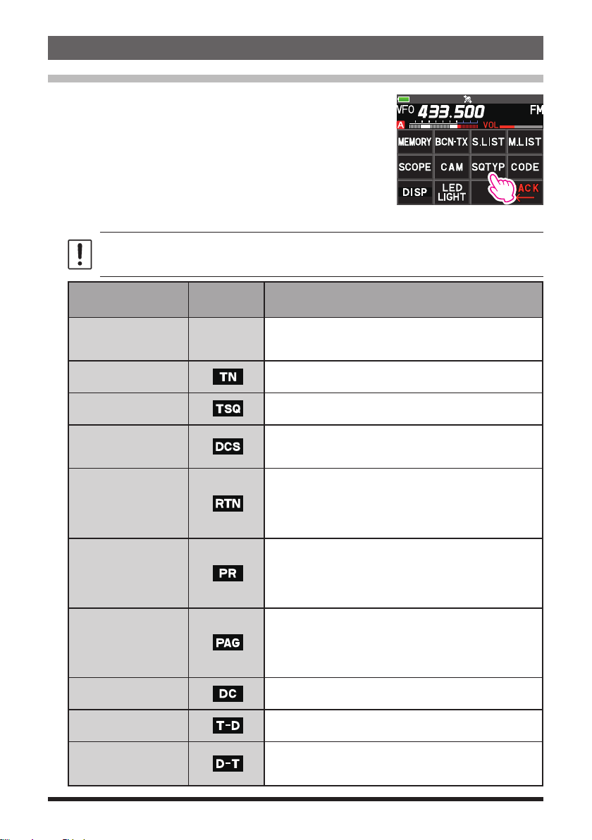
1. Press the [F MENU] key [SQTYP].
If [SQTYP] is not displayed, touch [FWD →] to display
[SQTYP] and then touch it.
2. Turn the DIAL knob and select the type of squelch, refer to the table below.
Tone squelch (CTCSS), DCS and the New PAGER (EPCS) functions do not operate in
the C4FM digital mode. Touch [MODE] to change to the Analog FM mode, or turn the
AMS function ON.
Squelch type
OFF
TONE
TONE SQL
DCS
REV TONE
PR FREQ
PAGER
D CD*
TONE-DCS*
D CD-TONE SQL*
Icon
indication
-
Description
Deactivates the tone squelch function and DCS function
OFF, then returns to the normal squelch operation in the
Analog FM mode.
Analog FM Transmissions contain the CTCSS tone.
Receives as a normal squelch operation.
Activates the CTCSS tone squelch function on Analog
FM receive.
Activates the Digital Code Squelch (DCS) function.
The DCS code may be selected from 104 codes (from
023 to 754).
Activates the reverse tone function.
Used to monitor communications based on the squelch
control system. When a signal contains the designated
tone, the squelch is not opened, and when the tone signal
disappears, the squelch opens, and communication starts.
Activates the no-communication squelch function for
radios.
The no-communication signal tone frequencies may
be specified within the range from 300 Hz to 3000 Hz
in steps of 100 Hz.
Activates a new two-tone CTCSS pager function.
When communicating with FT5DR/DE transceivers
among friends, specify personal codes (each code is
composed of two tones) so that only specific stations
are called.
Transmits the signal containing the DCS CODE.
Receives as a normal squelch operation.
Sends a tone signal when transmitting, and receives
the only signal matches the DCS code when receiving.
Sends the DCS CODE when transmitting and receives
only signals that contain a matching tone signal when
receiving.
9
*: Press and hold the [F MENU] key [SIGNALING] [10 SQL EXPANTION] set to
“ON”, “D CD”, “TONE-DCS” and “D CD-TONE SQL” setting values are activated.
3. Press the PTT switch to save the settings and return to normal operation.
• The squelch type may be set for each frequency band (BAND).
• The CTCSS and DCS squelch settings are also active during scanning. If scanning is
performed with the CTCSS and DCS squelch function activated, scanning stops only
when a signal containing the specified CTCSS tone or DCS code is received.
• Pressing the MONI/T-CALL switch allows signals that do not contain a tone or DCS code,
and signals with different tones, DCS codes, digital mode signals to all be heard.
• Press and hold the [F
the DCS code of the inverted phase.
] key [SIGNALING] [3 DCS INVERSION] allows to receive
MENU
Tone squelch feature
The tone squelch opens the speaker audio only when a signal containing the specified
CTCSS tone is received. The receiver will be quiet while waiting for a call from a specific
station.
The tone squelch function does not function in digital mode. Touch [MODE] to change the
communication mode to Analog FM mode or turn the AMS function ON.
Setting CTCSS Tone frequency
The tone frequency may be selected from 50 frequencies (from 67.0 Hz to 254.1 Hz).
1. Press the [F
If [SQTYP] is not displayed, touch [FWD →] to display [SQTYP] and then touch it.
2. Rotate the DIAL knob to select “TONE SQL”.
3. Press the PTT switch to save the settings and return to normal operation.
4. Press the [F
5. Rotate the DIAL knob to select the tone frequency.
6. Press the [BACK] key to save the setting and return to
normal operation.
MENU] key [SQTYP].
MENU] key] [CODE].
12 TONE SQL FREQ
TONE : 100.0 Hz
• The tone frequency setting is common with the squelch types as follows:
TONE, TONE SQL, REV TONE, TONE-DCS, D CD-TONE SQL
• The default setting is “100.0 Hz”
Searching for the CTCSS Tone transmitted by the other Station
The tone search function does not function in digital mode. Touch [MODE] to change the
communication mode to Analog FM mode or turn the AMS function ON.
Search and display the tone squelch CTCSS tone transmitted by the other station.
1. Press the [F
MENU] key [SQTYP].
If [SQTYP] is not displayed, touch [FWD →] to display [SQTYP] and then touch it.
2. Rotate the DIAL knob to select the “TONE SQL”.
3. Press the PTT switch to save the setting and return to normal operation.
10
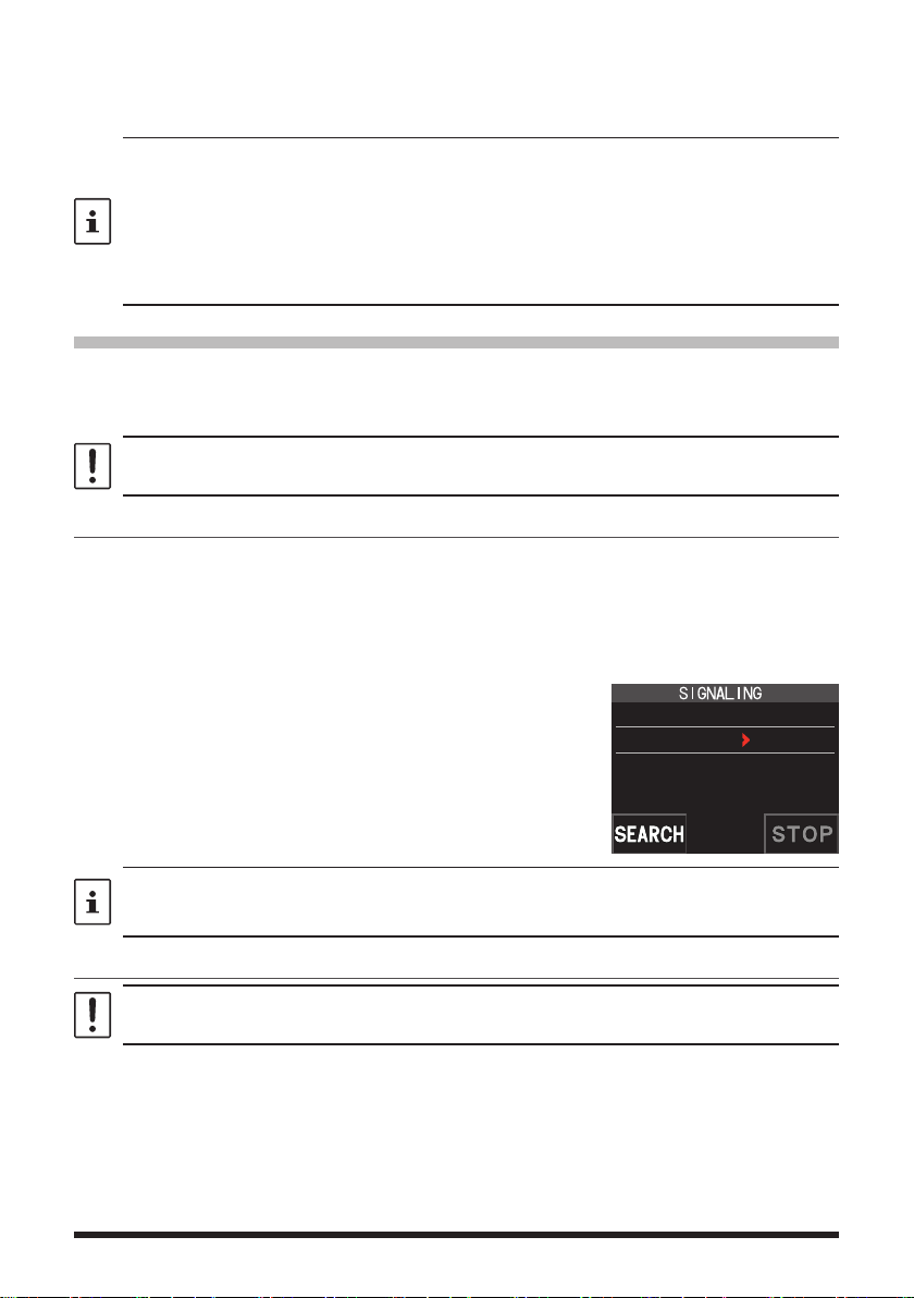
4. Press the [F MENU] key [CODE].
The setting screen of the tone frequency is displayed.
5. Touch [SEARCH].
• The transceiver begins searching for a matching
tone frequency.
12 TONE SQL FREQ
TONE : 123.0 Hz
• When a corresponding tone frequency is detected,
a beep sound is emitted, and the detected tone
frequency blinks. The searching stops for 5 seconds
and the audio is heard.
6. Touch [STOP] to stop searching.
7. Press the [BACK] key to save the detected tone frequency and return to normal
operation.
To set the transceiver operation when scanning stops, press and hold the [F
[SCAN] [4 SCAN RESUME]. This setting is common with the scan setting, tone search
function and DCS search function.
MENU
] key
Digital Code Squelch (DCS) feature
The Digital Code Squelch opens the speaker audio only when a signal containing the
specified DCS code is received.
The DCS code may be selected from 104 types (from 023 to 754).
The tone search function does not function in digital mode. Touch [MODE] to change the
communication mode to Analog FM mode or turn the AMS function ON.
Setting the DCS CODE
1. Press the [F MENU] key [SQTYP].
If [SQTYP] is not displayed, touch [FWD →] to display [SQTYP] and then touch it.
2. Rotate the DIAL knob to select “DCS”.
3. Press the PTT switch to save the setting and return to normal operation.
4. Press the [F
5. Rotate the DIAL knob to select the DCS code.
6. Press the [BACK] key to save the detected tone
frequency and return to normal operation.
MENU] key [CODE].
2 DCS CODE
DCS : 023
• The DCS code set by the above operation is the common setting for all transmissions
with a DCS Code (DCS, D CODE, T DCS, D TONE).
• The default DCS code is “023”.
11

Searching for the DCS Code Used by the Other Station
Search for the DCS code used by the other station.
1. Press the [F
MENU] key [SQTYP].
If [SQTYP] is not displayed, touch [FWD →] to display [SQTYP] and then touch it.
2. Rotate the DIAL knob to select “DCS”.
3. Press the PTT switch to save the setting and return to normal operation.
4. Press the [F
MENU] key [CODE].
The DCS code setting screen is displayed.
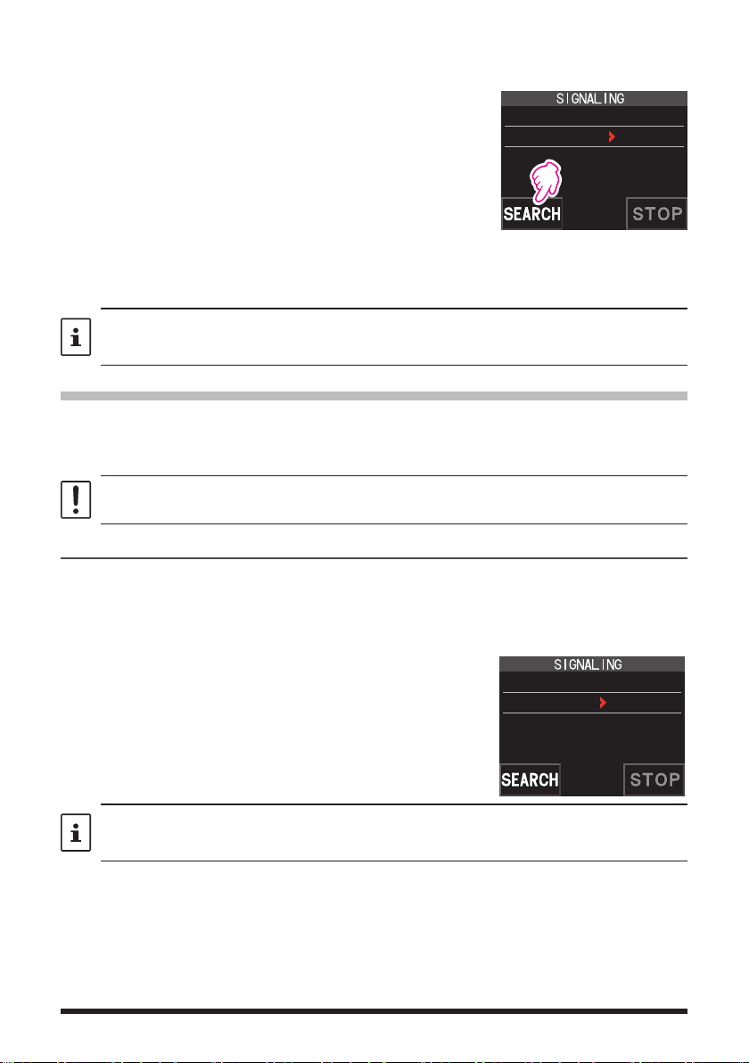
5. Touch [SEARCH].
• The transceiver starts to search for the DCS code.
• When a corresponding DCS code is detected, a
2 DCS CODE
DCS : 023
beep sound is emitted. The detected DCS code
blinks. The searching stops for 5 seconds and the
audio is heard.
6. Touch [STOP] to stop searching.
7. Press the [BACK] key to save the detected DCS code and return to normal operation.
To set the transceiver operation when scanning stops, press and hold the [F
[SCAN] [4 SCAN RESUME]. This setting is common for all scan settings, the tone search
function and DCS search function.
MENU
] key
Two-Tone CTCSS Pager Function
When using FT5DR/DE transceivers with a group of friends, setting the Two-Tone CTCSS
personal codes allows calling just the specific stations. Even when the person who is
called is not near the transceiver, the information on the LCD indicates that a call was
received.
The new two-tone CTCSS pager feature does not operate in digital mode. Touch [MODE] to
change the communication mode to Analog FM mode or turn the AMS function ON.
Using the Pager Function
1. Press the [F MENU] key [SQTYP].
If [SQTYP] is not displayed, touch [FWD →] to display [SQTYP] and then touch it.
2. Rotate the DIAL knob to select the “PAGER”.
3. Press the PTT switch to save the setting and return to normal operation.
Setting the Code for Your Station
Set the “pager code” to be called by other stations.
1. Activate the pager function by referring to “Using the pager function” above.
2. Press the [F
MENU] key [CODE].
If [CODE] is not displayed, touch [FWD →] to display [CODE] and then touch it.
12
3. Rotate the DIAL knob to select “CODE-RX”.
6 PAGER
ANS-BACK: OFF
CODE-RX : 05 47
CODE-TX : 05 47
4. Press the [F MENU] key to move the “u” icon to the first
element of the code.
Rotate the DIAL knob to select the first element of the
code from 01 to 50.
6 PAGER
ANS-BACK: OFF
CODE-RX : 05 47
CODE-TX : 05 47
5. Press the [F MENU] key to move the “u” icon to the
second element of the code.
Rotate the DIAL knob to select the second element of
the code from 01 to 50.
The same code cannot be use for both elements.
6 PAGER
ANS-BACK: OFF
CODE-RX : 05 47
CODE-TX : 05 47
6. Press the PTT switch to save the setting and return to
normal operation.
• The reverse combination works as the same code, that is “05 47” is the same as “47 05”.
• If the same code is specified for all individuals, all the individuals can be called at the
same time.
• The default code is “05 47”.
• When receiving the signals, the intermittent sound of the tone signal may be heard slightly.
Calling a Specific Station
The “pager code” may be set to call specific stations.
1. Activate the pager function by referring to “Using the Pager Function” (page 12).
2. Press the [F
MENU] key [CODE].
If [CODE] is not displayed, touch [FWD →] to display [CODE] and then touch it.
3. Rotate the DIAL knob to select “CODE-TX”.
4. Press the [F
MENU] key to move the “u” icon to the first element of the code.
Rotate the DIAL knob to select the first element of the code from 1 to 50.
5. Press the [F
MENU] key to move the “u” icon to the second element of the code.
Rotate the DIAL knob to select the second element of the code from 1 to 50.
The same code cannot be use for both elements.
6. Press the PTT switch to save the setting and return to normal operation.
7. Press the PTT switch to transmit a call to the specific station.
13
Receiving “pager code” calls from a Remote Station (Standby Operation)
When the Pager function is activated, and a call is received with a corresponding Code,
the audio is heard. When the PTT switch is pressed, the “
” icon blinks and the other
station's audio is heard regardless of whether the code matches or not. About 10 seconds
after the signal disappears, the “
” icon will light, and the sound of the unmatched
signal will not be heard.
Furthermore, when the Bell function (see below) is activated, the bell rings and the “
” icon
blinks when receiving calls from the other station.
Using the Pager Answer Back
when called by another station with a corresponding pager code, the transceiver is automatically placed in the transmit mode (for about 2.5 seconds) to notify the other station
that you are ready to communicate.
1. Activate the pager function by referring to “Using the Pager Function” (page 12).
2. Press the [F
MENU] key [CODE].
If [CODE] is not displayed, touch [FWD →] to display [CODE] and then touch it.
3. Press the [F
to select “ON”.
MENU] key, and then rotate the DIAL knob
6 PAGER
ANS-BACK: ON
CODE-RX : 05 47
CODE-TX : 05 47
4. Press the PTT switch to transmit a call to the specific station.
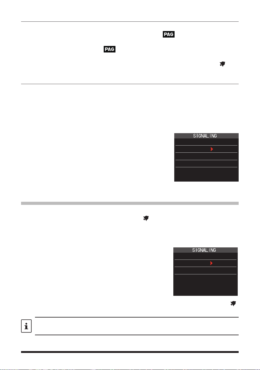
Notification of a Call from a Other Station by the Bell Function
The Bell may be set to sound an Alert when a call from another station containing a corresponding tone, DCS or pager code is received. “
” icon on the display blinks to provide
a later notice of the call from the other station.
1. Press and hold the [F
2. Press the [F
MENU] key.
MENU] key touch [SIGNALING] [1 BELL].
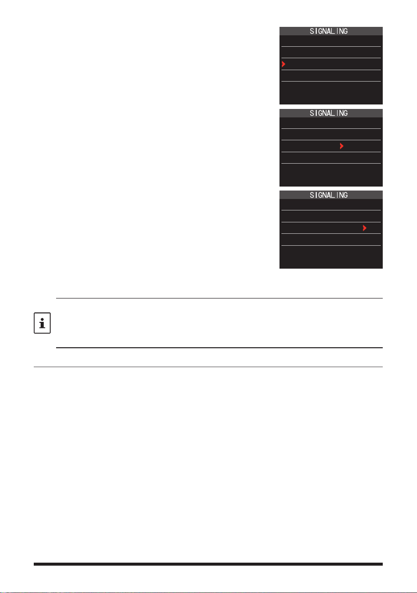
3. Rotate the DIAL knob to select “BELL”.
4. Press the [BACK] key, and then rotate the DIAL knob to
select “RINGER”, and then press the [F
MENU] key.
5. Rotate the DIAL knob to select the desired number of
1 BELL
SELECT : BELL
RINGER : 1time
times (1-20 times or continuous) the Bell rings.
• • • 1time ↔ 2times ↔ • • • ↔ 20times ↔ CONTI • • •
6. Press the PTT switch to save the setting and return to normal operation, and the “ ”
icon appears on the display.
If the setting is “CONTI” (continuous), the bell keeps sounding until an operation is made.
14

User Programmed Reverse CTCSS Decoder
The tone signal frequency can be set at 100 Hz intervals between 300 Hz and 3000 Hz
to mute the audio when receiving a signal containing a CTCSS tone matching the programmed tone.
1. Press the [F
2. Rotate the DIAL knob to select “PR FREQ”.
3. Press the PTT switch to save the setting and return to
normal operation.
4. Press the [F
The setting screen containing the CTCSS tone
frequencies is displayed.
5. Rotate the DIAL knob to select the desired CTCSS
tone frequency.
300Hz to 3000Hz (100Hz steps)
6. Press the PTT switch to save the setting and return to
normal operation.
MENU] key [SQTYP].
MENU] key [CODE].
7 PR FREQUENCY
1600Hz
15

Memory Function
Memory Channel List
Since memory channels are displayed in a list, you can easily recall the memory by
checking the frequency and memory tag display.
1. Press the [F
• If [MEMORY] is not displayed, touch [FWD →] to
display [MEMORY] and then touch it.
• You can switch between memory tag display and
frequency display by press and hold the [V/M •] key.
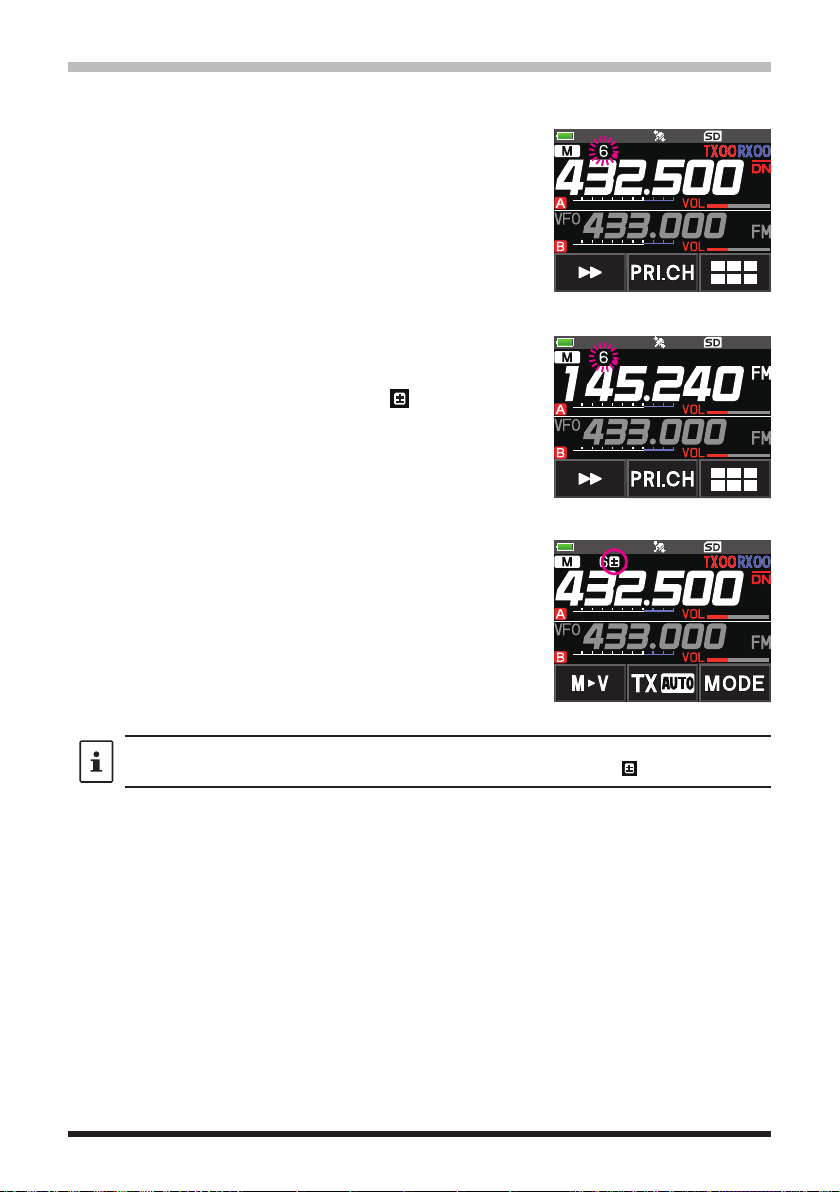
• The “ ” icon is displayed at the left of memory channels
set as skip memory, and the “
left of memory channels set as specified memory.
• Deleted memory channels are displayed in gray text.
• Touching [
channel to blink. Then turning the DIAL knob will fast
forward memories in 10 channel steps. To cancel fast
forward, touch [
2. Rotate the DIAL knob to select the desired memory channel.
3. Touch [ENT] to recall the selected memory channel and enter memory mode.
The Memory Channel Only Mode
The FT5DR/DE may be set to operated only in the registered memory channels.
1. While pressing the [V/M •] key, press and hold the POWER switch to turn the
transceiver ON.
• The memory channel only mode is ON, the previously selected memory channel is
recalled.
• Rotate the DIAL knob to select the memory channels.
• Touch and hold the frequency display to display the numeric keypad, enter a 3-digit
memory channel number, and then touch [ENT] to recall the memory channel.
• In the memory only mode, only the following functions will operate:
• Pressing the [V/M •] key, will sound the beep, “M-ONLY” will be displayed, and the
zCanceling Memory Only Mode
1. Turn the transceiver OFF; and then while pressing the [V/M •] key, press and hold the
POWER switch to turn the transceiver ON.
MENU] key [MEMORY].
1 145.030.00
2 439.700.00
3 145.620.00
4 432.500.00
” icon is displayed at the
], will cause the 10 digits of the memory
] again.
• Changing the communication mode (touch [MODE])
• The transmission mode setting of the AMS function (touch [TX AUTO], [TX FM] or [TX DN])
• Switching MAG groups (press the [BAND] key)
• Audio level adjustment
• Key lock function (press the POWER switch)
• Function menu MEMORY, DISP, LED LIGHT, SCAN, and D.RCV functions
• SQL level adjustment (press the [SQL] key)
• Group monitor (GM) function (press the [GM] key)
• WIRES-X function (press the [X] key)
function will not operate.
16
Using Memory Banks
The transceiver allows using up to 24 memory banks to be recalled with the sorted memory channels. One memory channel may also be registered in two or more memory banks
according to the intended use.
Example of registering memory channels to the memory banks:
Memory channels Memory banks
1 145.000 MHz
2 145.500 MHz
3 120.400 MHz
4 5 439.700 MHz
6 432.800 MHz
7 108.700 MHz
8 9 10 -
~
900 -
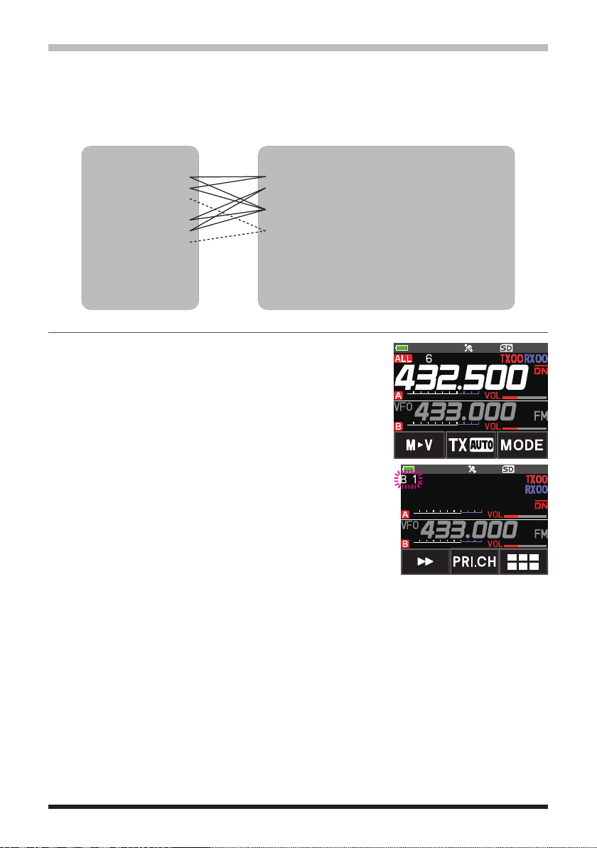
Registering to Memory Banks
1. Press the [V/M •] key to enter the memory mode.
2. Rotate the DIAL knob to recall the memory channel to
register in the memory bank.
BANK1 (1 - 100) 144 MHz Amateur Band Channels
BANK2 (1 - 100) 430 MHz Amateur Band Channels
BANK3 (1 - 100)
BANK4 (1 - 100) All Amateur Band Channels
BANK5 (1 - 100)
BANK6 (1 - 100) Air Band Channels
BANK7 (1 - 100)
BANK8 (1 - 100)
BANK9 (1 - 100)
BANK10 (1 - 100)
~
BANK24 (1 - 100)
3. Press and hold the [V/M •] key.
Memory channel will blink.
BANK 1
4. Rotate the DIAL knob to select the memory bank (BANK1
to BANK24) to register the memory channel.
The memory bank channels are displayed between the memory channel 1 (1CH), and
PMS memory channel U50.
5. Press the [V/M •] key.
The memory channel is registered in the selected memory bank and the transceiver
operation returns to the memory mode.
17
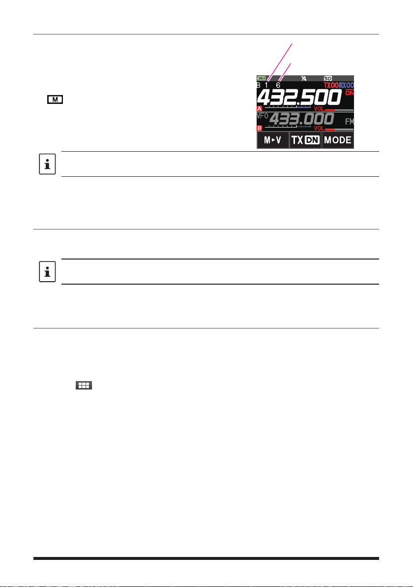
Open the Memory Bank display
1. Press the [V/M •] key to enter the memory mode.
2. Press the [F
MENU] key [BANK].
If [BANK] is not displayed, touch [BACK ←] to
Memory Bank Number
Memory Channel Number
display [BANK] and then touch it.
B1 to B24: The memory bank display
: The memory channel display
If no memory channel is registered, setting the following operation sounds the beep and “NO
BANK” will be displayed.
zDisable the memory bank display
1. Press the [F
MENU] key [MR].
If [MR] is not displayed, touch [BACK ←] to display [MR] and then touch it.
Open Memory Bank Channels
1. While the memory bank is displayed, press the [BAND] key.
2. Rotate the DIAL knob to select the memory bank (BANK1 to BANK24) to be recalled.
If no memory channel is registered, the memory bank may not be selected.
3. Press the [BAND] key or PTT switch.
The selected memory bank is activated.
Canceling a Memory Channel Registered in Memory a Bank
1. Recall the memory bank to cancel registering.
2. Press and hold the [V/M •] key.
3. Rotate the DIAL knob to select the memory channel to cancel registering to the
memory channel.
4. Touch [
], and then touch [M.DEL].
18

Assigning a Name to a Memory Bank
A name can be assigned to a memory bank using up to 16 characters.
The following types of characters can be entered:
• Alphabetic characters (1 byte and 2 byte letters, uppercase and lowercase
characters)
• Numbers (1 byte and 2 byte numbers)
• Symbols
1. Press and hold the [F
MENU] key touch [MEMORY]
[2 BANK NAME].
2. Touch the bank where you want to edit the tag.
• The character input screen is displayed.
• Use the numeric keys or DIAL knob, to input the
name characters.
• Touch 【
】: to move the cursor to the right
• For additional details on inputting a memory tag,
refer to “Text input screen” in the Operating Manual.
The default memory bank names are set from “BANK 1” to
“BANK24. Each name may be changed.
3. When input is complete, press the PTT switch to save
the characters and return to normal operation.
19
Split Memory
Two different frequencies, one for receive and another for transmit, may be registered to
a memory channel.
1. Register the receive frequency to a memory channel first.
• For additional details on registering to a memory channel,
refer to the “Registering to Memory Channels” in the
Operating Manual.
2. Set the transceiver to the desired transmit frequency.
3. Press and hold the [V/M •] key .
4. Rotate the DIAL knob to select the channel number that
the receive frequency was registered to on step1.
5. While pressing and holding the PTT switch, press the
[V/M •] key.
• The beep sounds and the split memory is saved.
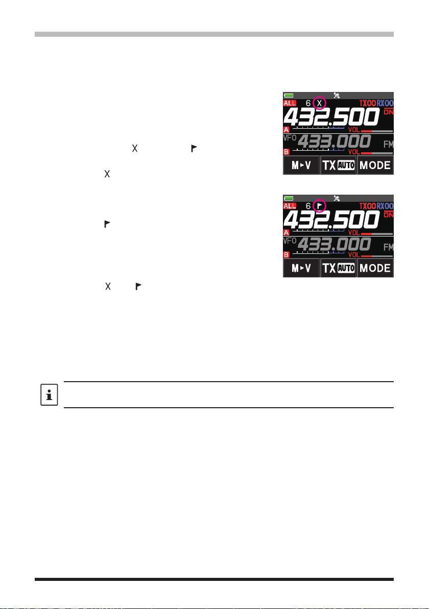
• While recalling the split memory, “
” is displayed on
the LCD.
Registering the receive
frequency.
Registering the transmit
frequency.
Recalling the split memory
While operating the split memory, Press the [F
and receive frequencies temporarily. When reversing the frequencies,“
key [REV], to reverse the transmit
]
MENU
20
” will blink.
Setting Skip Memory Channel and Specified Memory Channel
For efficient memory channel scanning, two types of memory channels may be designated, “skip memory channels” and “specified memory channels”. Set “Skip Memory Channels” will be skipped during the memory scanning; and only “Specified Memory Channels”
will be scanned during specified memory channel scanning.
1. Recall the memory channel to skip or specify.
2. Press and hold the [F
[5 MEMORY SKIP].
3. Rotate the DIAL knob to change as follows:
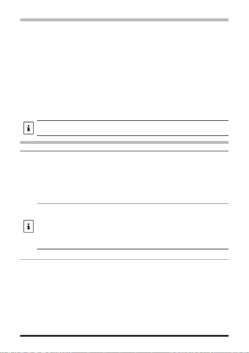
• • • OFF SKIP
• SKIP: Skip Memory Channel
” at the right of the memory channel
The “
number lights up, and then the channel is
skipped during scanning of memory channels.
• SELECT: Specified Memory Channel
The “
” at the right of the memory channel
number lights up, and then only designated
memory channels are scanned during memory
scanning.
• OFF: Normal Memory Channel
The “
” or “ ” at the right of the memory
channel number turns OFF.
zScanning Only the Specified Memory Channels
1. Recall the memory channel registered as a specified memory channel.
2. Press the [F
MENU] key [SCAN].
• If [SCAN] is not displayed, touch [BACK ←] to display [SCAN] and then touch it.
• Only the memory channels registered as the specified memory channels are
scanned.
MENU] key touch [MEMORY]
SELECT • • •
Skip Memory
Specified Memory
Unless two or more specified memory channels are registered, the specified memory
channel scanning does not function.
21
Skipping Unwanted Scan Frequencies (Skip Search Memory)
During the VFO scan, an unwanted frequency may be skipped by registering it to the “skip
search memory channels” in advance.
zSet the temporary scan stop to the skip search memory
1. Press and hold the [V/M •] key to temporarily stop the VFO scan.
2. Rotate the DIAL knob to select a skip search memory channel from 901-999.
Only skip search memory channels 901-999 may be selected.
3. Press the [V/M •] key.
The beep sounds, and the search skip channel is saved to memory, then the scan
resumes.
zSpecifying Unwanted VFO Scan Frequencies
1. In the VFO mode, set the frequency that you do not want to receive.
2. Register the skip search memory (901-999) with the same steps as “Registering to
Memory Channels” (see the Operating Manual).
The skip search memory may be deleted with the same steps as “Clearing Memories” (see
the Operating Manual). The deleted frequency is scanned again.
Programmable Memory Channel Scan (PMS)
Registering to the Programmable Memory Channels
50 sets of PMS memory channels (L1/U1 to L50/U50) are available.
• Register the lower and upper frequencies of the frequency range in a pair of
Programmable Memory Channels.
L££: Lower limit memory channel
U££: Upper limit memory channel
• For more details on registering frequencies to the memory channel, refer to the
“Registering to Memory Channels” in the Operating Manual.
• Make sure to use the corresponding numbers for the lower and upper limit memory
channels.
• Set the PMS memory channel for performing the Programmable Memory scanning (PMS)
as follows:
• The scan width of the upper and lower limit frequencies must be 100 kHz or more.
• The lower and upper limit memory channels must be within the same frequency band.
• The lower and upper limit memory channels must not be registered in reverse.
• The PMS memory channel must not be registered as a skip memory channel.
Performing Programmable Memory Channel Scan
The programmable memory channel scan allows scanning a specified frequency range
within the same frequency band.
1. Recall the PMS memory channel to which the lower limit (L££) or upper limit (U££)
of the frequency band is registered.
2. Press the [F
MENU] key [SCAN].
• If [SCAN] is not displayed, touch [BACK ←] to display [SCAN] and then touch it.
• Programmable memory channel scanning starts.
• During scanning, “PMSP££” appears on the upper left side of the display.
• If the DIAL knob is rotated while scanning is in progress, the scanning will continue
up or down in frequency according to the direction of the DIAL Knob rotation.
22
 Loading...