

Yaesu FL-2000B Instruction Manual

Downloaded by
Amateur Radio Directory
INSTRUCTION
MANUAL
FL-2000B
YAESU MUSEN CO., LTD.
TOKYO JAPAN

******************************************
FL-2000B LINEAR AMPLIFIER
******************************************
GENERAL
The YAESU FL-2000B Linear Amplifier is designed to match the "F" series
transceivers and transmitters in appearance and drive requirements to run high
power Snout covering the ham bands 80 through 10 meters.
The FL-2000B uses a pair of 572B/T160 transmitting triodes in a class B grounded
grid circuit configuration. The tubes are forced— air cooled by two very quiet high
speed internal fans.
Automatic Level Control circuit controls the exciter gain to allow the highest average
power without distortion caused by peak clipping. Changeover circuit biases the
tubes to cut-off, eliminating unwanted heat and diode noise generation when
receiving.
An internal changeover relay feeds the antenna to the exciter for barefoot operation
when the FL-2000B is turned off or is on standby condition. A built-in SWR bridge
measures SWR on by barefoot and linear operations.
The built-in solid state power supply requires no warm-up period and provides
excellent voltage regulation.
CAUTION
DO NOT TURN ON THE FL-2000B WITH THE TOPSHIELD COVER REMOVED.
THE HIGH VOLTAGE SAFETY LOCK SHORTS OUT THE HIGH VOLTAGE AND
WILL DAMAGE THE POWER SUPPLY CIRCUIT.
- 1 -

SPECIFICATIONS
Downloaded by
Amateur Radio Directory
Circuit : Grounded Grid Class B
Frequency Coverage : Ham bands 80 through 10 meters
Plate Input : 1200 Watts PEP, 1000 Watts CW and 600 Watts AM
Plate voltage : 2400 Volts DC
Drive Requirement : 100 Watts PEP
Input Impedance : 50 ohms, unbalanced
Output Impedance : 50 - 75 ohms, unbalanced
Third Order Distortion : 30 db or better at 1000 Watts PEP
Tube Complement : 2 x 572B/T160
Cooling : Forced-air cooling
Power Requirements : AC 100, 1 10 Volts 50/60Hz 17 Amps
AC 200, 220, 230 Volts 50/60Hz 9 Amps
Dimensions : 14
1/2
" Wide, 6
1/4
" High, 11
1/2
" Deep
Weight : 44 Ibs
FRONT PANEL CONTROLS
POWER - OFF : Rocker switch turns power on
OPER - TUNE. : Rocker switch applies Bias when standby and relay
is disengaged.
SWR - IP : Rocker switch selects either SWR or plate current
meter reading.
F - R : Rocker switch selects either forward or reflected
SWR bridge reading.
SENS : Potentiometer adjusts meter sensitivity for SWR
measurement.
PLATE : Plate capacitor in tank circuit.
INSTALLATION
The FL-2000B has been designed incorporating two safety locks to prevent
dangerous high voltage shock. However, extreme care is recommended when
servicing inside the cabinet
.
- 2 –

Unpacking
Carefully remove FL-2000B and tubes from their packing cartons and examine them
for any visible shipping damage, check the control knobs and switches for complete
freedom of action. Should any damage be apparent, notify the delivering carrier
immediately stating the nature of the damage in detail.
Tube Installation.
Tubes can be installed after removing the top cover (see SERVICING). First, check
to see if the tube holders at the tube sockets are loose enough to install tubes. If not,
loosen them. Notice the mark pin of the tube base comes to the right of the socket
for correct insertion into the socket.
Push the tubes straight in to insert them and fasten the tube holders. Insert the plate
caps on the top of the tubes. Check to make sure that the plastic choke coil has
enough clearance from the surrounding parts to avoid electrical short.
After replacing the top shield of the tube compartment and the top cover, the
amplifier can be connected for operation.
In general, care should be taken to insure that enough space is allowed around the
amplifier cabinet to permit adequate air circulation within the linear amplifier. Do not
cover the top of the FL-2000B with books, papers or other equipment. Do not insert
anything under the bottom of the FL-2000B or overheating may result.
POWER REQUIREMENT
The FL-2000B has a built-in power supply which can be operated from either 100,
117 or 220 volts AC 50-60 cps. The FL-2000B is shipped from the factory
connected to operate on 220 volts AC.
- 3 -
It is recommended that the FL-2000B is operated from its own 220 volt 10 amp or
Downloaded by
Amateur Radio Directory
greater circuit. If 117 or 100 volts is all that is available, it should be fused for 20
Amps, circuit conductors should be larger than #10 and no other equipment should
be operated from this circuit. Do NOT, under any circumstances, operate the FL2000B from a 115 volt lighting circuit, as the circuit conductors are not large enough
to carry this load.
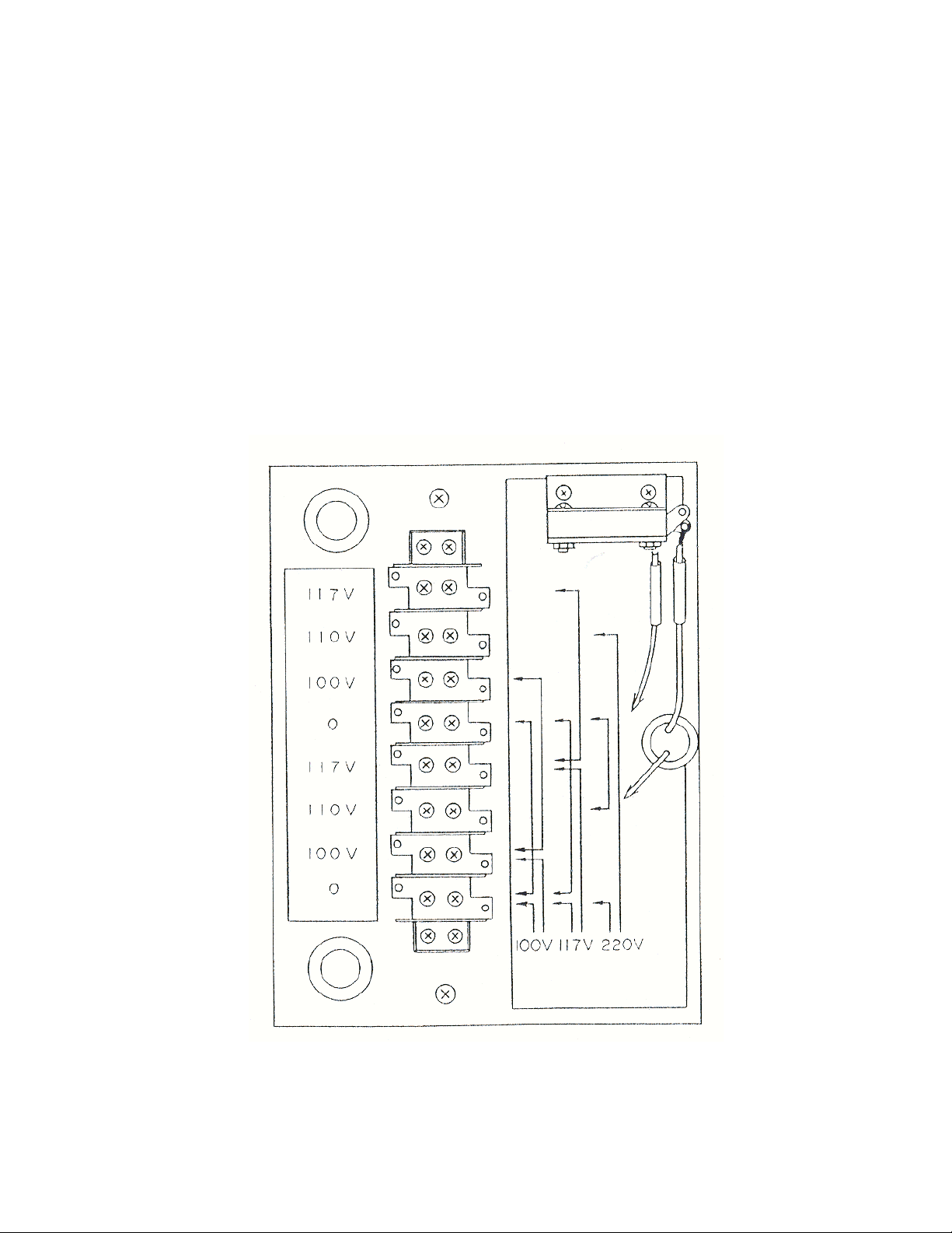
The following diagram shows the wiring connections for 1 10, 1 15 and 220 volt
operation. Connections must be made as shown or serious damage may result.
- 4 -

ANTENNA REQUIREMENT
The FL.-2000B has been designed for use with an antenna resonant at the operating
frequency and having approximate impedance within the limit of 40 to 80 ohms. The
nominal output impedance of the FL-2000B is 50 ohms. When the impedance of the
antenna used is far from this value, it is recommended that an antenna matching
network be used which will allow the FL-2000B to work into its nominal 50 ohm load
for maximum power transfer into the antenna.
GROUND REQUIREMENT
The FL-2000B should be connected to a good earth ground through as
short and as large a gauge wire as possible for best performance and maximum
safety. A connecting post marked "GND" is provided on the rear apron of the
chassis.
CAUTION
NEVER OPERATE THE FL-2000B WITHOUT FIRST CONNECTING IT TO AN
EARTH GROUND, AND AN ANTENNA OR 50 OHM DUMMY LOAD, OR SERIOUS
DAMAGE MAY RESULT.
EXCITER REQUIREMENT
To operate the FL-2000B at its maximum power input, it will be required that the
exciter deliver 100 Watts PEP SSB output. Our FT-400/500, FT-560, FT-200 and
FT-101 transceivers and FL-400 transmitter all have sufficient power to drive the
FL-2000B at its maximum input. The exciter should be placed as close to the
amplifier as practical to avoid long coax and ground connections.
ALC
On the rear of the FL-2000B, a terminal is provided for connection to the exciter of
the ALC voltage which controls the gain of the exciter to prevent distortion caused by
peak clipping.
- 5 -
 Loading...