

Page 1

Manual
MJK Data Transmitter 795
Valid from software version 830434
COMLI PROTOCOL
MJK Automation A/S
Byageren 7
DK-2850 Nærum
Denmark
Tel: +45 45 56 06 56
Fax: +45 45 56 06 46
www.mjk.com
Station ID:
795 Type:
795 Serial no:
M795GB0503
As our products are developed continuously,
we reserve the right to make any changes without prior notice.
Page 2

Data Transmitter 795
Konformitetserklæring
Vi, MJK Automation A/S,
DK-2850 Nærum, påtager os
det fulde ansvar for at produktet
som denne erklæring angår, er i
overensstemmelse med følgende
standard(er) eller andre
normdokument(er).
EN 50081-1:1995
EN 50082-1:1995
efter bestemmelserne i
direktiv
89/336/EØF; 93/68/EØF
Declaration of Conformity
We, MJK Automation A/S,
DK-2850 Nærum, declare under
our sole responsibility that the
product
MJK Data Transmitter 795
to which this declaration relates
is in conformity with the following
standard(s) or other normative
document(s).
EN 50081-1:1995
EN 50082-1:1995
following the provisions of
Directive
89/336/EWG; 93/68/EWG
Konformitätserklärung
Wir, MJK Automation A/S,
DK-2850 Nærum, erklären in
alleiniger Verantwortung, dass
das Produkt
auf das sich diese Erklärung
bezieht mit der/den folgenden
Nor me(en) oder normativen
Dokument(en) übereinstimmt.
EN 50081-1:1995
EN 50082-1:1995
Gemäss den Bestimmungen der
Richtlinie
89/336/EWG; 93/68/EWG
Declaration de conformite
Nous, MJK Automation A/S,
DK-2850 Nærum, déclarons
sous notre seule responsabilité
que le produit
auquel se réfère cette
déclaration est conforme á la
(aux) norme(s) ou autre(s)
document(s) normatif(s)
EN 50081-1:1995
EN 50082-1:1995
conformément aux dispositions
de Directive
89/336/EWG; 93/68/EWG
Dichiarazione di conformità
Noi, MJK Automation A/S,
DK-2850 Nærum, dichiariamo
sotto la nostra esclusiva
responsabilità che
l’apparecchio
MJK Data Transmitter 795
al quale questa dichiarazione
si riferisce, è conforme alla
seguente normativa(e) standard o ad altri documenti di
normativa(e)
EN 50081-1:1995
EN 50082-1:1995
conformemente alla
disposizioni della Direzione
89/336/EWG; 93/68/EWG
Declaración de Conformidad
Nosotros, MJK Automation A/S,
DK-2850 Nærum, declaramos
bajo nuestra única
responsabilidad que el producto
al cual se refiere esta
declaración, está en
conformidad con la(s)
siguente(e) norma(s) u otros
documentos normativos
EN 50081-1:1995
EN 50082-1:1995
según las disposiciones de la(s)
directiva(s)
89/336/EWG; 93/68/EWG
M795GB0503
2
SW ver. 830434
Page 3

Data Transmitter 795
Contents
1 Introduction .......................................... 5
1.1 Versions........................................................5
1.2 Communications protocols ........................... 5
1.3 MJK-Link™ .................................................. 6
1.4 About this manual ........................................ 6
1.5 Safety instructions ........................................6
1.6 Product identification .................................... 6
1.6.1 Standard versions 7
1.6.2 Versions with built-in options 7
2 Mechanical mounting ..........................8
2.1 Mounting on a wall ....................................... 8
3 Electrical mounting .............................. 9
3.1 Power supply................................................ 9
3.2 In- and output signals 9
3.2.1 I/O terminals, 8 DI/8 DO/4 AI 9
3.2.2 I/O terminals, 12 DI/4 DO/4 AI 10
3.2.3 I/O terminals, 16 DI/4 AI 10
3.3 Connection examples ................................. 11
3.3.1 Digital inputs 11
3.3.2 Digital outputs 11
3.3.3 Analogue inputs 11
3.3 Connection of Pump Controller 704 ...........12
3.4 Connection of communications ports ......... 12
3.4.1 Communications port 12
3.4.2 Built-in modem 12
4 The front panel ................................... 13
4.1 Display and keys 13
4.2 Menu structure ...........................................13
5 Functional menus ............................... 14
5.1.1 F0 - Program version, time and date 14
5.1.2 F0 - Interlock, operation or alarm signal 14
5.1.3 F0 - Internal flag, operation
or alarm signal 14
5.1.4 F0 - Limits, high/low 14
5.1.5 F0 - Digital inputs,
operation or alarm signal 14
5.2 F1 - Digital inputs on/off ............................. 14
5.3.1 F2 - Digital outputs on/off 14
5.3.2 F2 - Internal flag on/off 14
5.4 F3 - Limits - High/Low ................................ 15
5.5 F4 - Analogue input value # ........................ 15
5.5.1 F5 - Analogue input scaling 15
5.5.2 F5 - Analogue input on
Pump Controller 704 15
5.6 F6 - Counter for inputs ...............................15
5.7 F7 - Counter for time ..................................15
5.8 F8 - Alarm / Alarm number ........................16
5.9.1 F9.1 - Stormflow volume 16
5.9.2 F9.2 - Stormflow calculation 16
5.10 F# - Modem/Line status .............................16
5.11 F* - Communication status ......................... 16
6 Programming of main functions........ 17
6.1 Select language ..........................................17
6.2 Set time and date ....................................... 17
6.3 Automatic change between
summer time and winter time .....................17
6.4 Access code enabled/disabled ................... 17
6.4.1 Enter password 17
6.5 Calculation of average values on
analogue inputs .......................................... 17
6.6 Data logging interval ...................................17
6.7 Tone / pulse dialing ..................................... 17
6.8 Alarm call on power failure.......................... 17
6.9 Number of incoming rings before answer ... 18
6.10 ID. no. for the Data Transmitter ................... 18
6.11 Automatic reset of alarms ...........................18
6.11.1 Call on automatic alarm reset 18
6.12 Start time for operational reports ................18
6.13 795 telephone number ...............................18
6.14 SMSC telephone number ...........................18
6.15 RS485 function........................................... 18
6.15.1 Master ID number 18
7 Programming of analogue inputs ..... 19
7.1 Select analogue input ................................. 19
7.2 0 - 20 or 4 - 20 mA input ............................ 19
7.3 Scaling at 0 / 4 mA ..................................... 19
7.4 Scaling at 20 mA ........................................19
7.5 Monitoring of high limit ............................... 19
7.5.1 Set high limit 19
7.5.2 High limit operation / alarm 19
7.5.3 Dialout on high limit 19
7.5.4 Signal delay for exceeding high limit 19
7.6 Monitoring of low limit ................................. 19
7.6.1 Set low limit 20
7.6.2 Low limit operation / alarm 20
7.6.3 Dialout on high limit 20
7.6.4 Signal delay for exceeding low limit 20
7.7 Divisor ........................................................20
8 Programming of digital inputs ........... 20
8.1 Select a digital input ................................... 20
8.2 NO or NC ................................................... 20
8.3 Operational or alarm input ..........................20
8.3.1 Dialout on alarm 20
8.4 Signal delay ................................................20
9 Programming of digital outputs ........21
9.1 Select a digital output ................................. 21
9.2 NO or NC ................................................... 21
9.3 Time controlled output................................ 21
9.4 ON time ...................................................... 21
9.4.1 Time before start 21
M795GB0503
3
SW ver. 830434
Page 4

Data Transmitter 795
10 Programming of logical functions ..... 21
10.1 Select the output to receive the result
of the logical function.................................. 21
10.2 Select logical function .................................21
10.2.1 Select signals for the logical function 21
10.2.2 Operational or alarm signal on
internal flag 22
10.2.3 Dialout when alarm signal on
internal flag 22
10.2.4 Signal delay on internal flag 22
11 Programming of interlock .................. 22
11.1 Interlock of this station ................................ 22
11.2 Interlock interval.......................................... 22
11.3 Selection of substation ...............................22
11.4 Interlock active / inactive ............................ 23
11.4.1 Start of interlock 23
11.4.2 Stop interlock 23
11.4.3 Receivers telephone / ID number 23
11.4.4 Receiver's output 24
12 Programming of Pump Controller(s) . 25
12.1 704 connected ...........................................25
12.2 Call on alarm or system error on 704 .......... 25
12.2 Programming of the
internal Pump Controller .............................25
12.2.1 Select level signal 25
12.2.2 Start level for pump no. 1 25
12.2.2 Stop level for pump no. 1 25
12.2.3 Levels in use in 795 25
12.2.4 Start level for pump no. 2 25
12.3.2 Stop level for pump no. 2 25
12.3.3 Alternation of pumps 25
13 Telephone list for alarms ................... 26
13.1 Telephone number 1-9 ............................... 26
13.2 Number type .............................................. 26
13.2.1 Telephone number 26
13.2.2 Enter pager message 26
13.2.3 Enter SMS message 27
13.2.4 Pause between calls 27
15 Programming of 702 ComTroller ....... 29
15.1 Select 702 ..................................................29
16 Alarms ................................................. 30
16.1 Operational or alarm signal ......................... 30
16.2 Alarm calls .................................................. 30
16.3 Reset of alarms .......................................... 30
15.3.1 Automatic reset of alarms 30
17 Factory settings ................................. 31
18 Signal lists .......................................... 33
19 Register list ......................................... 37
20 Menu structure ................................... 44
20.1 Functional menus .......................................44
20.2 Programming menus ..................................45
A Appendix............................................. 50
A1 Technical specifications .............................. 50
A2 Number of signals available ........................50
A3 Inputs and outputs ..................................... 50
A4 Dimensions ................................................. 50
B Appendix............................................. 51
B1 Maintenance ............................................... 51
B2 Service codes ............................................. 51
B2.2 Forced setup
without reset of datalogger 51
B2.3 Forced setup
including reset of datalogger 51
B2.4 Baud rate and communication method 51
B2.5 Activation of SIM card for GSM/GPRS
modem 51
B2.6 Total reset 51
B3 Software upgrade .......................................51
B4 SMSC telephone numbers .........................52
B5 Spare parts................................................. 52
14 Programming of stormflow calculation .. 27
14.1 Stormflow calculation .................................27
14.2 Stormflow calculation in use ....................... 28
14.2.1 Zero point input no. 28
14.2.2 Level signal for flow calculation 28
14.2.3 Number of Q(h) points 28
14.2.4 Height value [h] for level point 28
14.2.5 Flow value [Q] for level point 28
M795GB0503
4
SW ver. 830434
Page 5
Data Transmitter 795
1 Introduction
Thank you for choosing an MJK Data Transmitter
795. A great effort has been put into developing a
product, which complies with all demands.
MJK Data Transmitter 795 is mounted in the field
and with its digital in- and output and analogue
input it is capable to receive and transmit most
types of digital and analogue signals. From a
built-in RS232 serial port, the MJK Data Transmitter 795 can communicate directly with other
equipment i.e. a pc, PLC or a Scada system.
MJK Data Transmitter 795 can with one click on
the mouse or from a telephone call activate digital
output and/or read in- and outputs, alarm signal
type for the latest 9 alarms and all logged data.
All settings, alarms and logged data can be read
in the display, from easy to use functionnal
menus.
MJK Data Transmitter 795 can be supplied in
versions that communicates via a built-in GSM
modem or telephone modem, or in versions for
radio modem.
MJK Data Transmitter 795 is easy to install and
operate, but read the instruction manual carefully
in order to make optimum use of the unit.
You can allways contact your sales reprsentative
or the MJK Automation Hotline in case of doubt
or for guidance. Try also to log onto http://
www.mjk.com.
1.1 Versions
MJK Data Transmitter 795 is as standard
supplied in the following hardware versions:
- 8, 12 or 16 digital inputs
- 0,4 or 8 digital outputs
- 4 analogue inputs
- 1 or 2 RS232 ports
Display of a pumping station from a pc with the
monitoring program MJK-Link™.
MJK Data Transmitter 795 can also be programmed to make a telephone call when there is an
alarm and transmit the alarm as text to a pc or
SCADA system and to a cell phone as SMS text.
The Data Transmitter 795 has a bult in battery for
telephone calls at power failure.
The RS 232 ports is used as connection to MJK
Pump Controller 704 and to connection of a PC
for configuration or reading of data in the field for
i.e. a portable PC or for configuration or reading
of data, when the Data Transmitter 795 is used
as data
logger.
1.2 Communications protocols
MJK Data Transmitter 795 can be connected to a
distribution station either through a serial
connection (RS232-RS 485), a built-in Hayes
compatible telephone modem, a data radio or a
GSM modem.
Communication complies with one protocol
which must be followed by master and slave.
Data Transmitter 795 is always the slave, i.e. the
Data Transmitter must receive a command before
it can reply. MJK Data Transmitter 795 is supplied
with Comli PLC-protocol as standard. The
following historical data are available in this
protocol:
- Time counter on digital inputs, total, total
today, total yesterday and the latest 24 hours,
all with 1 hour interval.
An MJK Data Transmitter 795 with built-in modem
can transmit alarms as SMS messages directly to
the cell phone of employee on duty.
M795GB0503
- Analogue values stored with 5 min. interval 24
hours back, and in the extended log with a
user defined logging interval.
5
SW ver. 830434
Page 6

1.3 MJK-Link™
The Windows based program MJK-Link™ can be
applied to monitor one or several MJK Data
Transmitter 795. Via a PC with modem it is
possible with MJK-Link™ to read values, modify
setpoints and read datalogger for e.g. storm flow
values. All settings in Data Transmitter 795 can
be implemented via MJK-Link™.
Furthermore, MJK Link™ can be used to control
the MJK Pump Comtroller 704. This facitily is
used when e.g. MJK Data Transmitter 795 and
MJK Pump Controller 704 is used together.
This manual covers MJK Data Transmitter 795 in
Comli versions for communication via telephone
modem, GSM modem or closed radio networks.
1.4 About this manual
The manual is divided into 4 main sections:
1: Introduction
Presentation of Data Transmitter 795 and this
manual.
Data Transmitter 795
Explosion hazardous areas
MJK Data Transmitter 795 is not approved for
use in explosion hazardous areas.
All current local and national standards and
regulations regarding installation and use of Ex
approved material, certifications and safety
instructions for Ex equipment that have been
used in connection with installation of Data Transmitter 795 must be strictly observed.
1.6 Product identification
Check that the item(s) delivered corresponds to
the ordered item(s). The item number is printed
on a label that is sticked onto the packing.
2: Mounting
Information for performing mechanical and
electrical mounting.
3: Basic settings
A look through the most common settings.
4: Field operation
A look through all settings for special
applications of Data Transmitter 795.
1.5 Safety instructions
1: Read this manual carefully.
2: Be aware of the environment on the installa-
tion site. Wear necessary protective
equipment and follow all current safety
regulations.
3: MJK Data Transmitter 795 can give out start
signals to dangerous machinery. Therefore, it
must be ensured that eventually connected
machinery and other equipment are
effectively being put out of service by i.e.
removal of main fuses, lock main- and/or
security switches in off position before
commencing setting, fault finding, service and
maintenance work etc.
➀➀
➀
➀➀
➁➁
➁
➁➁
➂➂
➂
➂➂
➃➃
➃
➃➃
➀➀
➀ Item number
➀➀
➁➁
➁ Item description
➁➁
➂➂
➂ Serial number
➂➂
➃➃
➃ Communications program
➃➃
An identical marking can be found on the right
hand side of the cabinet:
4: There is a risk of lethal electrical shock from
some of the terminals on Data Transmitter
795. Be careful not touch these while the unit
is in operation.
Repair
1: Repair must only be made by MJK or a
representative approved by MJK.
M795GB0503
6
SW ver. 830434
Page 7

Data Transmitter 795
1.6.1 Standard versions
This manual covers the following standard versions with Comli protocol:
Item no.: In- and outputs: Communication:
204510
204511
204512
204520
204521
204522
MJK Data Transmitter 795 with 2 X RS232 and
4 AI / 8 DI / 8 DO
4 AI / 12 DI / 4 DO
4 AI / 16 DI / 0 DO
4 AI / 8 DI / 8 DO
4 AI / 12 DI / 4 DO
4 AI / 16 DI / 0 DO
built-in telephone modem.
(Item no. 204510/204511/204512)
2 × RS232 w. modem
2 × RS232 w. modem
2 × RS232 w. modem
1 × RS232 wo. modem
1 × RS232 wo. modem
1 × RS232 wo. modem
1.6.2 Versions with built-in options
The following type options can be built into Data
Transmitter 795:
Varenr.: Betegnelse:
204570 Galvanically insulated RS232 port
204571 Galvanically insulated RS485 port
204572 Galvanically insulated port for TP 6000
204573 Galvanically insulated port for Niros UHF
204574
205105 GSM modem complete w. aerial
205106 GPRS modem complete w. aerial
Galvanically insulated port for external modem
The factory mounted options can be determined
read on the terminal box lid:
MJK Data Transmitter 795 delivered from factory
with galvanically insulated communications port.
MJK Data Transmitter 795 with 1 X RS232 and 1 x
communications option port.
(Item no. 204520/204521/204522)
MJK Data Transmitter 795 delivered from factory
with built-in GSM-modem.
For both types of option applies that the data
transmitter is mounted and connected like a standard data transmitter.
Please see separate documentation for the builtin options.
M795GB0503
7
SW ver. 830434
Page 8

2 Mechanical mounting
Data Transmitter 795
explosion hazardous areas!
Data Transmitter 795 is IP65 enclosed, and can
be mounted outdoors directly on a wall or a
railing, eventually by means of MJK rain roof
200115 and MJK universal fitting 200205.
must not be mounted in
Data Transmitter 795
Dimensional drawing for mounting screws.
See also page 51.
MJK rain roof 200115 mounted on pole with MJK
universal bracket 200205.
Data Transmitter 795 can also be mounted in a
panel by means of MJK panel mounting kit
200105.
Data Transmitter 795 mounted in a panel with MJK
panel mounting kit 200105.
2.1 Mounting on a wall
The cabinet is mounted using three screws. The
upper screw is used for the suspension and the
two lower screws is used to fix the cabinet.
Remove the terminal box lid to gain access to the
two lower mounting holes.
The cabinet is suspended by the upper screw and.
fastened with the two lower screws.
The distance between the mounting screws is
shown on the dimensional drawing.
Please observe minimum distance if more than
one cabinet is mounted.
You will find a jig in full size at the back of this
manual.
MJK Data Transmitter 795 must be mou
ted vertically in order to comply with the IP68
standard.
M795GB0503
X
Do not use a screw machine!
8
SW ver. 830434
Page 9

Data Transmitter 795
3 Electrical mounting
Data Transmitter 795
explosion hazardous areas!
Data Transmitter 795 must not be connected to
the power supply before all connections are
Remove the terminal lid and the front panel to
gain acces to all terminals.
3.1 Power supply
Data Transmitter 795 can be supplied from both
230 V AC and 24 V DC.
must not be mounted in
made.
Terminal: Designation:
Protective ground
N 230 V AC neutral
L 230 V AC live
- 24 V DC negative
+ 24 V DC positive
Please note, that 24 V DC will not be available on
the terminals marked '24 V DC forsyning' unless
the Data Transmitter is fed from the mains.
3.2 In- and output signals
Data Transmitter 795 is delivered in 3 different I/O
variants; 4AI / 8DI / 8DO, 4AI / 12DI / 4DO and
4AI / 16DI respectively.
Specifications:
DI: Passive with common negative, max. 24 V DC.
(Optocoupler med 10 kΩ serial resistor)
Trig voltage: < 1 V DC = Off, > 10 V DC = On,
pulse length > 100 ms.
DO: Voltage free relay contacts,
max. 1 A @ 24 V DC / 0,5 A @ 48 V AC.
AI: 0/4 - 20 mA or 0 - 1 V DC.
Input impedance = 50 Ω.
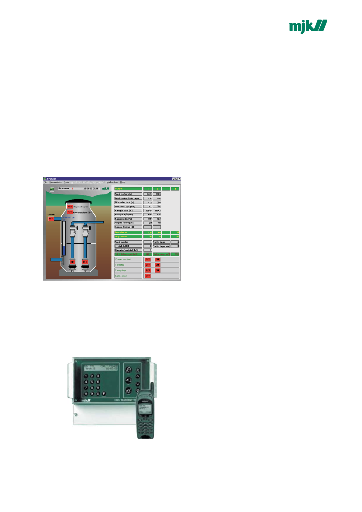
3.2.1 I/O terminals, 8 DI/8 DO/4 AI
DO 1
DO 2
DO 3
DO 4
DO 1/2/3/4 common -
DO 5
DO 6
DO 7
DO 8
DO 5/6/7/8 common -
Shield for RS232 to 704
Signal ground for RS232 to 704
24 V DC out +
24 V DC out -
DI 1 +
DI 2 +
DI 3 +
DI 4 +
DI 1/2/3/4 common DI 5 +
DI 6 +
DI 7 +
DI 8 +
DI 5/6/7/8 common AI 1 +
AI 1 AI 2 +
AI 2 AI 3 +
AI 3 AI 4 +
AI 4 Rx for RS232 to 704
Tx for RS232 to 704
M795GB0503
9
SW ver. 830434
Page 10
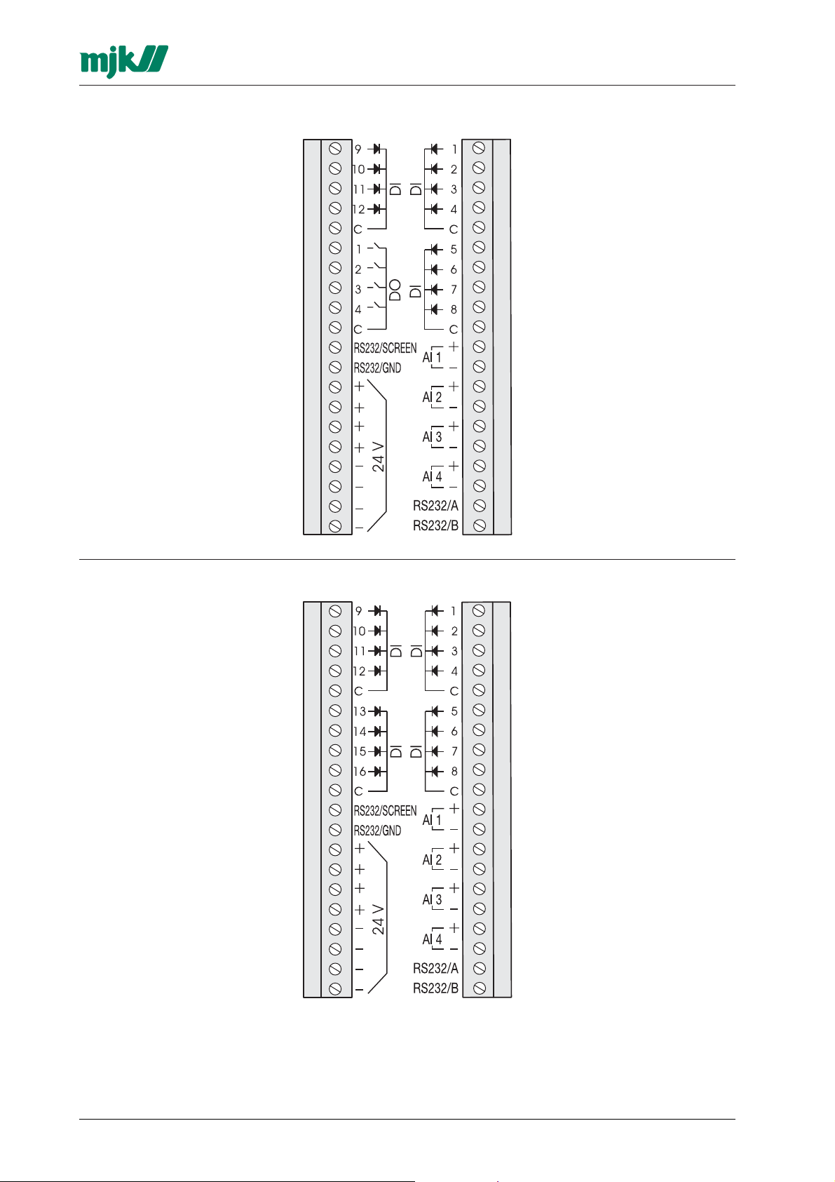
3.2.2 I/O terminals, 12 DI/4 DO/4 AI
Data Transmitter 795
DI 9 +
DI 10 +
DI 11 +
DI 12 +
DI 9/10/11/12 common -
DO 1
DO 2
DO 3
DO 4
DO 1/2/3/4 common -
Screen for RS232 to 704
Signal ground for RS232 to 704
24 V DC out +
24 V DC out -
DI 1 +
DI 2 +
DI 3 +
DI 4 +
DI 1/2/3/4 common DI 5 +
DI 6 +
DI 7 +
DI 8 +
DI 5/6/7/8 common AI 1 +
AI 1 AI 2 +
AI 2 AI 3 +
AI 3 AI 4 +
AI 4 Rx for RS232 to 704
Tx for RS232 to 704
3.2.3 I/O terminals, 16 DI/4 AI
DI 9 +
DI 10 +
DI 11 +
DI 12 +
DI 9/10/11/12 common -
DI 13 +
DI 14 +
DI 15 +
DI 16 +
DI 13/14/15/16 common -
Screen for RS232 to 704
Signal ground for RS232 to 704
24 V DC out +
24 V DC out -
DI 1 +
DI 2 +
DI 3 +
DI 4 +
DI 1/2/3/4 common DI 5 +
DI 6 +
DI 7 +
DI 8 +
DI 5/6/7/8 common AI 1 +
AI 1 AI 2 +
AI 2 AI 3 +
AI 3 AI 4 +
AI 4 Rx for RS232 to 704
Tx for RS232 to 704
M795GB0503
10
SW ver. 830434
Page 11
Data Transmitter 795
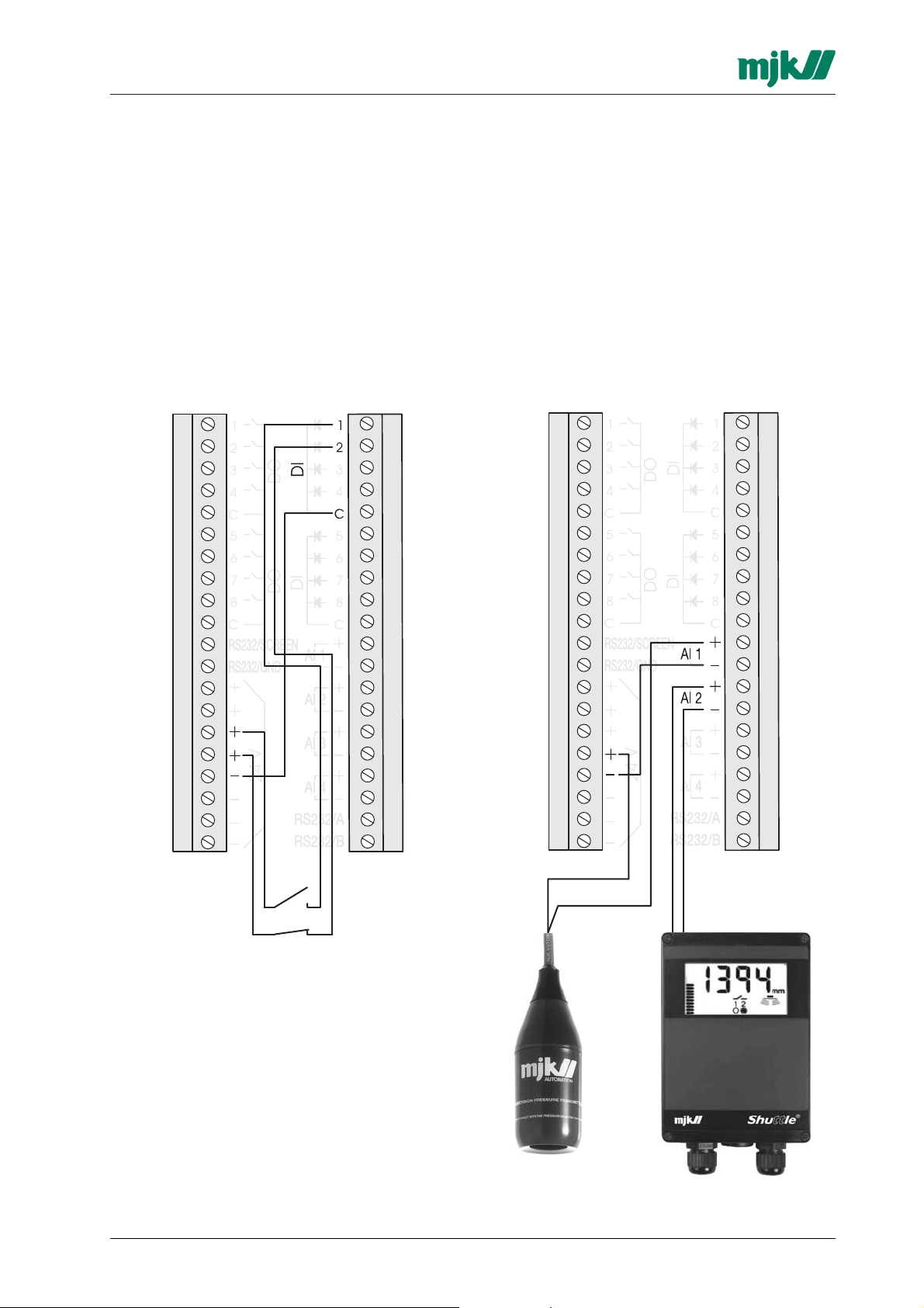
3.3 Connection examples
3.3.1 Digital inputs
The digital inputs are passive, i.e. they need to be
supplied from an external power source or from
the terminals marked '24 V'.
Note, that the inputs has common negative in
groups of 4 inputs.
A common installation error is that an input is
not connected to the correct negative terminal!
The inputs can be individually configured to be
normally open (NO) or normally closed (NC).
3.3.3 Analogue inputs
The analog inputs are passive. i.e. they must be
supplied from an external power source or from
the terminals marked '24 V'.
Every input have its own plus and negative terminal.
A common installation fault is that an input is
not connected to the correct negative terminal!
The input range can be individually configured to
0-20 mA or 4-20 mA.
Above diagram show an example of connecting two
switches to DI1 and DI2. Note the common
negative terminal!
3.3.2 Digital outputs
The digital outputs are voltage-free relay contacts
with a capacity of max. 24 V DC / 1 A or max. 48
V AC / 0,5 A resistive load.
The outputs can be individually configured to be
normally open (NO) or normally closed (NC).
M795GB0503
A passive mA signal
from a pressure
transmitter.
11
An active mA signal from
a level transmitter.
SW ver. 830434
Page 12
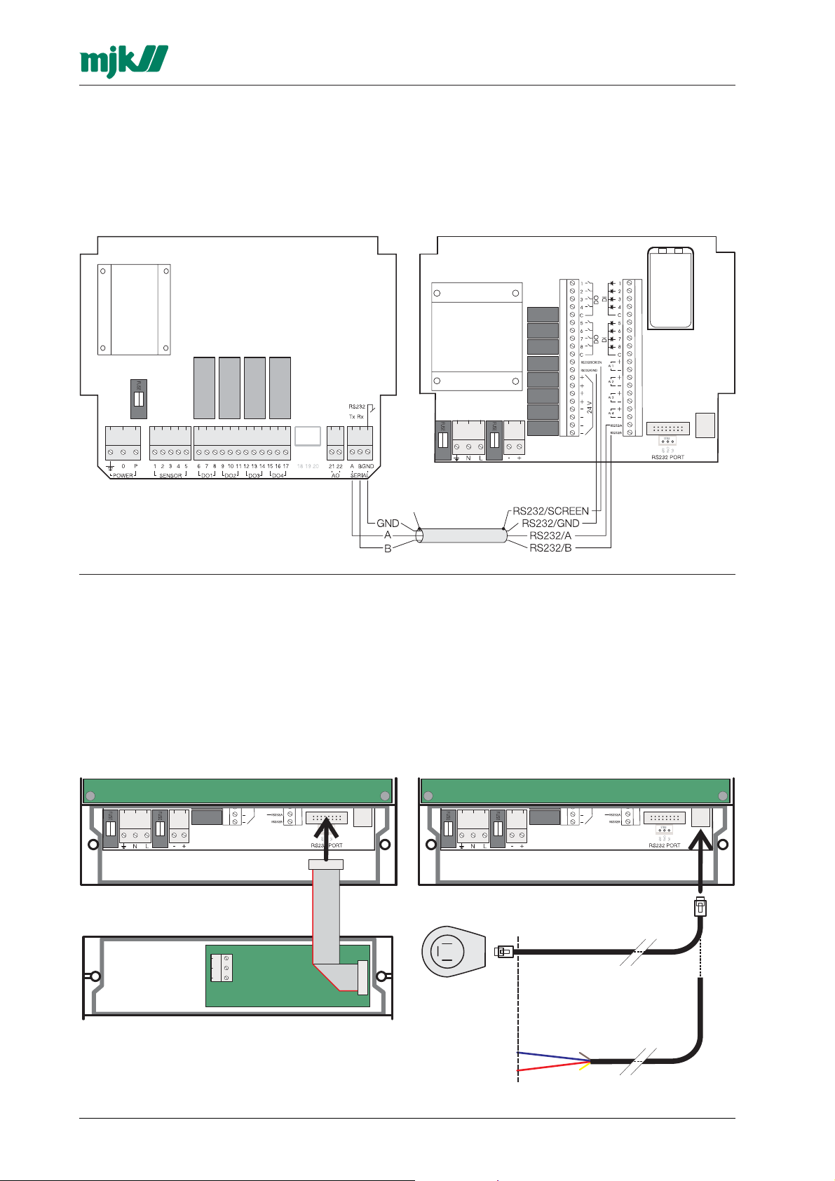
3.3 Connection of Pump Controller 704
Only the RS232 port on the plug-in terminals of
the Data Transmitter can be used for connecting
a MJK Pump Controller 704. A screened, twisted
pair cable must be used, and it should be
connected as shown below:
Data Transmitter 795
The shield must not be connected to the Pump
Controller 704.
Max. cable length is 15 metres.
DO NOT CONNECT
3.4 Connection of communications ports
(Only item no. 204520 / 21 / 22.)
3.4.1 Communications port
All options listed in section 1.6.2 is supplied with
a flat cable, that just need to be mounted in the
communications port socket on the lower PCB.
See also separate documentation for the option
in question.
THE SHIELD IN
THIS END!
3.4.2 Built-in modem
The built-in modem can be connected to a
telephone outlet with the enclosed RJ11 cable. If
the modem should be connected to a terminal,
the cable should be stripped and only the red og
blue wire need to be connected. The two other
wires are not used.
M795GB0503
12
SW ver. 830434
Page 13

Data Transmitter 795
4 The front panel
Display
2 x 24 digit backlit
alphanumerical display
for indication of user
menus and measuring
values.
4.1 Display and keys
Numerical keys
The keys 0-9, #,
used to enter
are
*
telephone numbers,
delays, analogue
scaling etc.
ESC. key
This key is used to go
back to the previous
menu, or to cancel a
selection. Press this
key 2 or 3 times to
revert to functional
indication.
Functional key F
The function key are
used for selecting the
different functional
menus to be displayed.
The illustration show
the function menu F0
for program version,
time and date.
MENU key
This key is used to
switch between main
menus and submenus.
ENTER key
The ENTER kry is used
to change between the
main menu and
submenus and to go
through the submenus.
The ENTER kay is
always used to confirm
a selection in a
submenu.
Arrow keys
The arrow keys are
sed for altering the
current setting. In a
sub-menu the current
selection is always
shown in the upper
line, and the alternative
selection is shown in
brackets in the lower
line. The arrow keys
are used to select an
alternative setting. The
arrow keys are also
used to select input
and output number.
The ↑ key increase
and the ↓ key
decrease a value.
4.2 Menu structure
Above figure is an overview of the general function of the functional keys.
INDICATION
MENUS
MAIN
MENU
SUBMENU W.
SELECTION
SUBMENU W.
SELECTION
See also page 42.
MAIN
MENU
M795GB0503
13
SW ver. 830434
Page 14

5 Functional menus
Data Transmitter 795
5.1.1 F0 - Program version, time and date
Menu F0 displays date og and time. Moreover, it
will display the current communications protocol
and program version.
5.1.2 F0 - Interlock, operation or alarm signal
Menu F0 followed by 1 x 'down arrow' will display
which signals that initiate the 9 programmable interlock sequences:
'A': alarm signal, '+': operation signal,
'-': not in use.
5.1.3 F0 - Internal flag, operation or alarm signal
Menu F0 followed by 2 x 'down arrow' will display
which signals that are linked to the internal flags:
5.2 F1 - Digital inputs on/off
Menu F1 indicates if the digital inputs are set ON
or OFF. Up to 8 inputs are shown simultaneously.
If there are more than 8 inputs, the remaining
inputs will be displayed by pressing one of the
arrow keys:
Note, that a delay period can be set for every digital input so that the digital input can go ON for a
short period without triggering an eventual alarm.
When the input is OFF, an empty field is
shown. When the input goes ON, a flashing field
is shown during the delay time, after which a field
is shown constantly.
5.3.1 F2 - Digital outputs on/off
Menu F2 displays whether the digital outputs are
set ON or OFF:
'A': alarm signal, '+': operation signal, '-':
not in use.
5.1.4 F0 - Limits, high/low
Menu F0 followed by 2 x 'down arrow' will
indicate which analogue inputs that are linked to
a high/low alarm limit, and also if the limit will
release an operational or alarm signal:
'A': alarm signal, '+': operation signal, '-':
not in use.
5.1.5 F0 - Digital inputs, operation or alarm signal
Menu F0 followed by 4 (and 5) x 'down arrow'
display which digital inputs, that releases an operation or alarm signal:
'A': alarm signal, '+': operation signal, '-':
not in use.
A delay period can be set for every digital output.
This delay period must run out before the output
are activated.
When the output is OFF, an empty field is
shown. When the output goes ON, a flashing field
are shown during the delay time, after which a
field are shown constantly.
5.3.2 F2 - Internal flag on/off
Menu F2 followed by 1 x 'down arrow' will display
the status for the internal flags.
M795GB0503
14
SW ver. 830434
Page 15
Data Transmitter 795
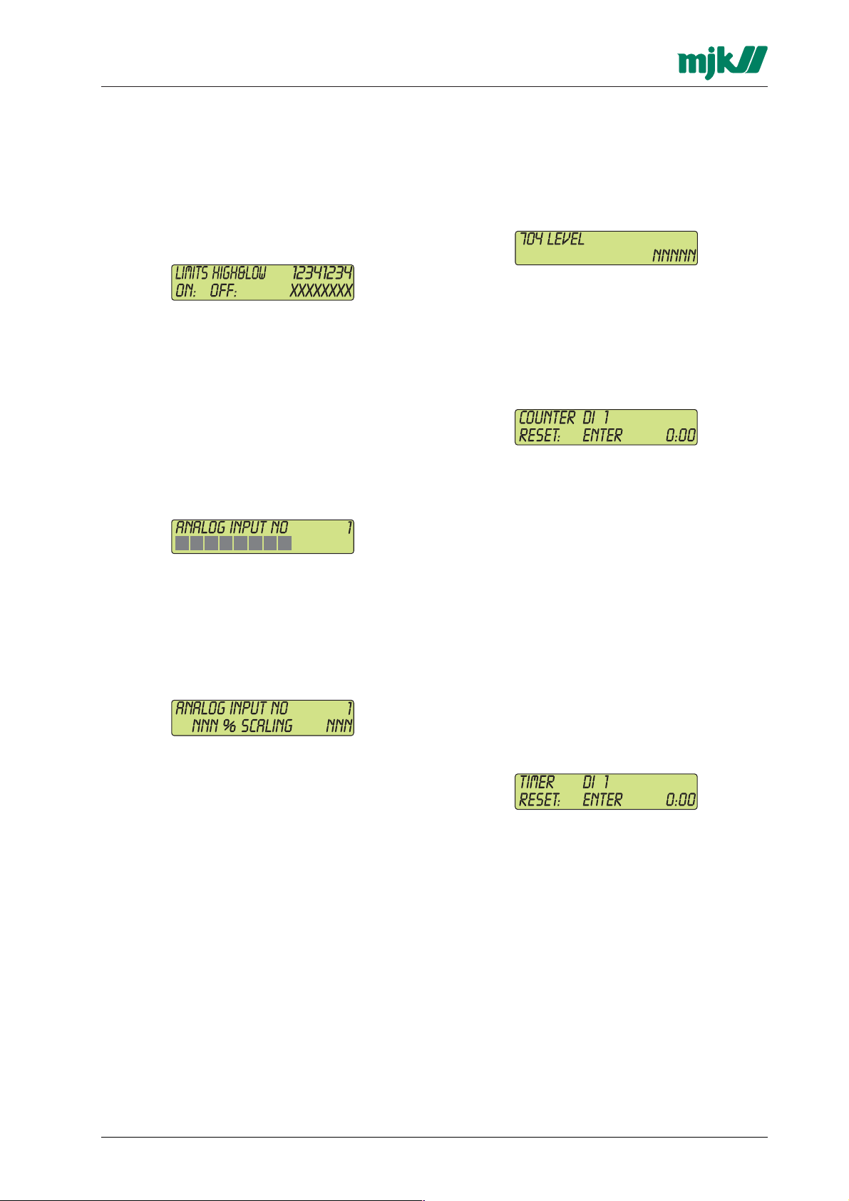
5.4 F3 - Limits - High/Low
Menu F3 indicates if high and low limit is ON or
OFF for the analogue inputs. The first four digits
indicate if the high limit setting is exceeded and
the last four digits indicate if the low limit setting is
exceeded:
A delay time can be set individually for each
analogue input in that the the input can exceed the
limit for a short period without activating an alarm.
An empty square is displayed when the limit is
not exceeded. When the limit is exceeded, a solid
square is displayed. If a delay period is set, the
square will flash during the delay period.
5.5 F4 - Analogue input value #
Menu F4 indicates the value of the analogue inputs
as a bargraph:
Select the desired input with the arrow keys or
the numeric keys.
5.5.1 F5 - Analogue input scaling
Menu F5 indicates the value of an analogue input
as a percentage and the mA signal and as a
scaled value:
Select the desired input with the arrow keys or
the numeric keys.
5.5.2 F5 - Analogue input on Pump Controller 704
Menu F2 followed by 1 x 'down arrow' display
the value of the analogue input on the Pump
Controller 704 (if connected):
Please observe that the value is collected directly
from the Pump Controller 704 and is not scaled.
5.6 F6 - Counter for inputs
Whenever a digital input or an analogue high/low
limit is active, it will be recorded by a counter. The
number is displayed in menu F6:
Use the arrow keys to change between:
- digital input 1 - 8/12/16
- analogue high limit 1 - 4
- analogue low limit 1 - 4
In addition, the numerical keys 1 - 8 can be used
to select the desired input.
The selected counter can be reset by pressing
the ENTER key.
5.7 F7 - Counter for time
Menu F7 indicate for how long the digital input
and the analogue high and low limits have been
active. Time counters is running continuously
such as if the input is set to OFF for some time
and then is set to ON, the counter will count from
the last value. The time is displayed in hours and
minutes:
The scaled value is determined by the
programming of the analogue input.
If the value represents e.g. a level measurement
in a tank, and the level normally varies between 2
m and 3 m, the analogue input will normally be
programmed so 2 m corresponds with '200' (low
value) and 3 m corresponds with '300' (high
value).
A level of 2,5 m will then give a scaled readout of
250 and 50 %.
If the scaled value should be shown as '2,5', it is
possible to set a divisor for each input. In this
example the divisor should have the value 100.
See also section 7.
M795GB0503
Use the arrow keys to change between:
- digital input 1 - 8/12/16
- analogue high limit 1 - 4
- analogue low limit 1 - 4
In addition, the numerical keys 1 - 8 can be used
to select the desired input.
The selected counter can be reset by pressing
the ENTER key.
15
SW ver. 830434
Page 16
Data Transmitter 795
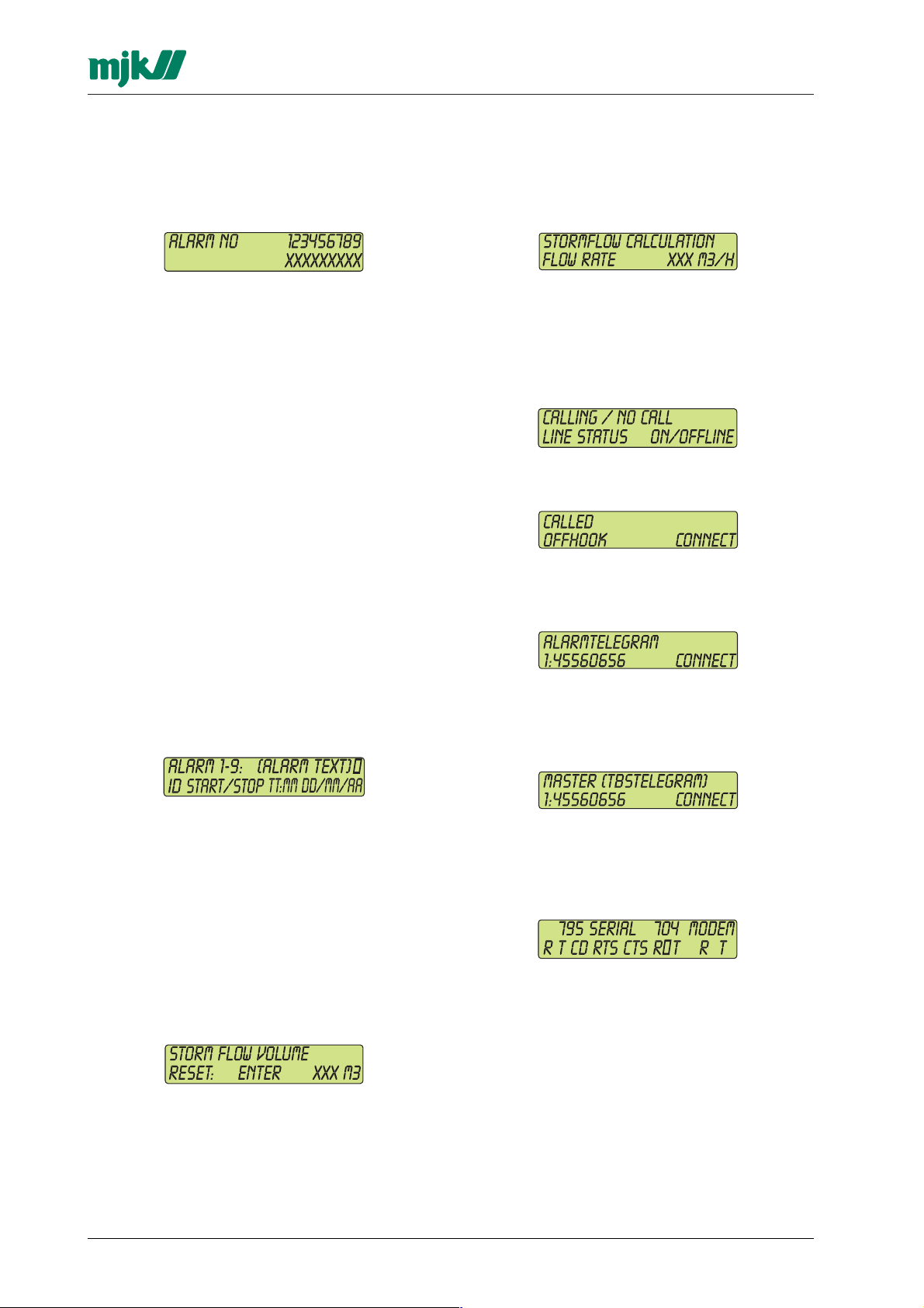
5.8 F8 - Alarm / Alarm number
Menu F8 indicate if the last 9 alarms are ON or
OFF:
Each time a new alarm is activated, it will be
recorded as alarm no. 1 and all other recorded
alarms will move down one place and alarm 9 will
be deleted. When the alarm for one input has
been ON one time it must be set to OFF before a
new alarm from the same input is accepted as an
alarm.
If the alarm has not been reset and another 9
alarms occur, i.e. the first alarm become no. 10
and therefore will become invisible in the alarm
list, this alarm will be reset automatically.
A flashing square is shown when an alarm
goes ON.
If the alarm are being reset but is still active, a solid square is shown constantly. When the alarm
goes OFF again, a square is shown constantly.
By means of the arrow keys or by entering the
alarm number, the status, type and timestamps
for on and off time can be displayed. Whenever
an alarm goes ON, the input number and start
time will be recorded. Similarly, when the alarm is
reset, the reset time is recorded, and when the
alarm goes OFF, the end time will be recorded:
5.9.2 F9.2 - Stormflow calculation
Whenever a stormflow occur, the flow is
3
displayed as m
/h in menu F9-2:
5.10 F# - Modem/Line status
(Only for versions with built-in telephone modem
or GSM modem.)
Menu F# displays the status of outgoing alarm
calls or incoming calls:
The following is displayed during an incoming
call:
The following is displayed during an outgoing
alarm call to one of the telephone numbers in the
telephone number list:
When Data Transmitter 795 interlocks another
Data Transmitter 795 i.e. in order to perform a
remote start or stop of a pump, the following is
displayed:
'ID' indicates the ID number of the Data Transmitter itself.
If the Data Transmitter are configured as a Master
in a multidrop system, the 'ID' can also be the ID
number of a connected Slave unit.
Return to normal operating display with the arrow
keys or by prssing the '0' key.
5.9.1 F9.1 - Stormflow volume
Menu F9 displays the recorded stormflow
volume.
The counter can be reset with the ENTER key.
M795GB0503
5.11 F* - Communication status
Menu F* indicate the communication status on
the serial port, the port to Pump Controller 704,
and the built-in telephone modem:
795 serial: R = Rx, T = Tx, CD = Carrier Detect,
RTS = Request to send og CTS = Clear to send.
704: R = Rx, T = Tx and = Pump Controller
704 not interlocked / Pump Controller 704
interlocked. The Pump Controller 704 signal to
the Data Transmitter that the Pump Controller
704 will not activate any control outputs, because
the Pump Controller are interlocked.
16
SW ver. 830434
Page 17

Data Transmitter 795
6 Programming of main functions
6.1 Select language
Select the desired language with the arrow keys
and confirm with ENTER.
6.2 Set time and date
Enter time and date with the numerical keys or
the arrow keys. Confirm with ENTER:
Just press ENTER at all entries if changes are not
needed in order to proceed to the next menu.
6.3 Automatic change between summer
time and winter time
Select if the clock should change automatically
between summer time and winter time:
6.5 Calculation of average values on
analogue inputs
The value of an analogue input is recorded every
second, and every 5 minutes the values is logged. If averaging of the analogue values are
selected, an average of the analogue value over
the last 5 minutes will be calculated and logged.
If averaging is not selected, the analogue value at
the actual time will be logged.
Use the arrow keys to select and confirm with
ENTER.
6.6 Data logging interval
The data logging interval is used for the extended
logging function, where the value for the analogue
input and the level from MJK Pump Controller
704 is stored.
Use the arrow keys to select and confirm with
ENTER.
Just press ENTER at all entries if changes are not
needed in order to proceed to the next menu:
6.4 Access code enabled/disabled
Select if an access code is required to gain access to the remaining system menus. This
function make it possible to protect the system
configuration from unauthorized changes:
Use the arrow keys to select and confirm with
ENTER.
6.4.1 Enter password
If access code protection is selected, a 4-digit
access code is required in order to gain access
to the remaining system menus.
The interval between loggings can be chosen
amongst the following values: 30 sec. (00:30), 1
min. (01:00), 5 min. (05:00), 10 min. (10:00), 30
min. (30:00) and 1 hour (60:00).
Use the arrow keys to select and confirm with
ENTER.
6.7 Tone / pulse dialing
Select between pulse or tone dialing from a
telephone modem:
Use the arrow keys to select and confirm with
ENTER.
6.8 Alarm call on power failure
If alarm call at power failure is selected, the Data
Transmitter will call the first telephone number in
the telephone list when the power supply fail. A
power failure will not be detected before the
supply has been gone for minimum 30 sec.
Hereby alarm calls on short power surges are
avoided.
M795GB0503
Use the arrow keys to select and confirm with
ENTER.
17
SW ver. 830434
Page 18

Data Transmitter 795
6.9 Number of incoming rings before
answer
Set the number of rings (1 to 5) before Data
Transmitter 795 answer the call.
Use the arrow keys or numerical keys 1 to 5 to
select and confirm with ENTER.
6.10 ID. no. for the Data Transmitter
The ID number is used for identification of the
individual data transmitters.
Use the arrow keys or numerical keys and
confirm with ENTER.
6.11 Automatic reset of alarms
Select if incoming alarms should be automatically
reset when the alarm condition disappears.
6.13 795 telephone number
Enter the telephone number that the Data Transmitter is connected to. The number is used as ID
no. in connection with transmission of SMS
alarms through landlines.
Use the numerical keys and confirm with ENTER.
6.14 SMSC telephone number
SMS messages need to be dialed to a specific
SMS gateway, that will handle the further transmission through the cellphone network.
Use the numerical keys and confirm with ENTER.
Telephone numbers to SMSC gateway can be
found in Appendix B.
6.15 RS485 function
This function is only available on Data Transmitter
795 with RS485 port.
If 'NO' are selected, all incoming alarms need to
be reset manually.
Use the arrow keys and confirm with ENTER.
6.11.1 Call on automatic alarm reset
If 'Automatic reset of alarms' have been selected
as described in the previous section, there will be
an option to select if the Data Transmitter should
perform a call, if an alarm condition disappear
and therefore releases an automatic reset of an
alarm.
Use the arrow keys and confirm with ENTER.
6.12 Start time for operational reports
Many plant managers want to have the
operational reports displaced so they will elapse
between i. e. 07:00 to 06:59. Enter the desired
displacement counted from midnight:
Select if this Data Transmitter 795 should be a
Master (the unit sending out alarms), or if this
Data Transmitter 795 should be a Slave which is
interconnected to another Master via the RS485
port:
Use the arrow keys and confirm with ENTER.
6.15.1 Master ID number
Select the Master ID for this Data Transmitter 795
if it is set to Master, or select the Slave ID for the
unit in the multidrop cluster which should receive
alarms and relay them via modem or radio:
Use the arrow keys and confirm with ENTER.
Use the arrow keys or numerical keys and
confirm with ENTER.
M795GB0503
18
SW ver. 830434
Page 19

Data Transmitter 795
7 Programming of analogue inputs
7.1 Select analogue input
Select the desired analogue input with the arrow
keys and confirm with ENTER.
7.2 0 - 20 or 4 - 20 mA input
Select input type with the arrow keys and confirm
with ENTER.
7.3 Scaling at 0 / 4 mA
Set the scaling of the low (0/4) mA value.
NB! The setting for the low mA value must be
lower than the setting for the high mA value! (See
next section.)
Use the numerical keys and confirm with ENTER.
7.4 Scaling at 20 mA
Set the scaling of the high mA value.
7.5.1 Set high limit
Set the upper limit value that should cause a
recording in the operational or alarm log - see
also section 13, "Operational or alarm signal".
In case the input are not scaled, 20 mA on the
analogue input will correspond to 9999.
Use the arrow keys or numerical keys and
confirm with ENTER.
7.5.2 High limit operation / alarm
Select if a high limit excession should be
recorded in the alarm log or the operational log see also section 15, "Operational or alarm signal".
Use the arrow keys and confirm with ENTER.
7.5.3 Dialout on high limit
Select if a high limit activation should cause a
dialout attempt.
NB! The setting for the high mA value must be
higher than the setting for the low mA value! (See
previous section.)
Use the numerical keys and confirm with ENTER.
7.5 Monitoring of high limit
Select if exceeding a high limit should be
recorded or not.
Use the arrow keys and confirm with ENTER.
Use the arrow keys and confirm with ENTER.
7.5.4 Signal delay for exceeding high limit
Select the period in which the analogue value can
exceed the high limit without activating an alarm:
Use the arrow keys (double arrow for minutes
and single arrow for seconds) and confirm with
ENTER.
7.6 Monitoring of low limit
Select if exceeding a low limit should be recorded
or not.
Use the arrow keys and confirm with ENTER.
M795GB0503
19
SW ver. 830434
Page 20

Data Transmitter 795
8 Programming of digital inputs
7.6.1 Set low limit
Set the lower limit value that should cause a
recording in the operational or alarm log - see
also section 13, "Operational or alarm signal".
In case the input are not scaled, 0 / 4 mA on the
analogue input will correspond to 0.
Use the arrow keys or numerical keys and
confirm with ENTER.
7.6.2 Low limit operation / alarm
Select if a low limit excession should be recorded
in the alarm log or the operational log - see also
section 15, "Operational or alarm signal".
Use the arrow keys or numerical keys and
confirm with ENTER.
7.6.3 Dialout on high limit
Select if a low limit activation should cause a
dialout attempt.
(Maximum period is 8 hours.)
8.1 Select a digital input
Select the desired digital input with the arrow
keys and confirm with ENTER.
8.2 NO or NC
Select if the input should be active (ON) when
there is a signal on the input or passive (OFF)
when there is no signal on the input.
Use the arrow keys and confirm with ENTER.
8.3 Operational or alarm input
Select if an activation of the input should be
recorded in the alarm log or in the operational log
- see also section 15, "Operational or alarm signal".
Use the arrow keys and confirm with ENTER.
8.3.1 Dialout on alarm
Select if an activation of the digital input should
cause a dialout attempt:
Use the arrow keys and confirm with ENTER.
7.6.4 Signal delay for exceeding low limit
Select the period in which the analogue value can
exceed the low limit without activating an alarm:
Use the arrow keys (double arrow for hours/
minutes and single arrow for seconds) and
confirm with ENTER.
7.7 Divisor
Set the desired divisor value for the analogue input. The divisor has only significance for
displaying of analogue values in function menu
F5, and not to the values that are transmitted to
other data transmitters or SCADA systems.
The divisor has no significance for the setting of
high or low limits.
Use the arrow keys and confirm with ENTER.
8.4 Signal delay
Select the period in which the digital input can be
active without causing an alarm or a recording of
an operational signal: (Maximum period is 8
hours.)
Use the arrow keys (double arrow for hours/
minutes and single arrow for seconds) and
confirm with ENTER.
Use the arrow keys or numerical keys and
confirm with ENTER.
M795GB0503
20
SW ver. 830434
Page 21

Data Transmitter 795
9 Programming of digital outputs
9.1 Select a digital output
Select the desired digital output with the arrow
keys and confirm with ENTER.
9.2 NO or NC
Select if the relay contact should be open (NO) or
closed (NC), when the output is not active.
Use the arrow keys and confirm with ENTER.
9.3 Time controlled output
Select if the output should go ON and stay ON
when the Data Transmitter receive a start signal
('FIXED'), or if the output should go ON when the
Data Transmitter receive a start signal and stay
ON for a pre-set period of time ('TIME').
If 'FIXED' are selected, the Data Transmitter need
a stop signal in order to deactivate the output.
10 Programming of logical functions
This menu gives the possibility to program simple
logical functions like AND, OR, and SET/RESET
based on different digital signals in both Data
Transmitter 795 and the Pump Controller 704 (if
connected).
Since it is also possible to set internal flags in
Data Transmitter 795, it will be possible to make
combina-tions of several logical function and thus
obtain PLC-like logical functions in the Data Transmitter 795.
10.1 Select the output to receive the result of
the logical function
The result of a logical function can be sent to an
internal flag or directly to a digital output.
Select the desired signal with the arrow keys and
confirm with ENTER.
10.2 Select logical function
Select the desired logical function for the signal.
Use the arrow keys and confirm with ENTER.
9.4 ON time
Select the period in which the output should be
active, if the output is set to be 'TIME' controlled.
Use the arrow keys (double arrow for minutes
and single arrow for seconds) and confirm with
ENTER.
9.4.1 Time before start
Select the delay time for activation of the output
relay. The delay time is from the moment the Data
Transmitter receive an ON command and until the
relay output will be activated.
Use the arrow keys (double arrow for minutes
and single arrow for seconds) and confirm with
ENTER.
Use the arrow keys and confirm with ENTER.
10.2.1 Select signals for the logical function
Select the signals to be used for the logical function.
In the left hand side of the display is shown the
previous selected signal type to receive the result
of the logical function together with the selected
logical function.
In the right hand side of the display is shown the
input signals for the selected logical function.
M795GB0503
21
SW ver. 830434
Page 22

1: Select the upper input signal with the arrow
keys and confirm with ENTER.
2: After that, select the lower input signal and
confirm with ENTER.
Please note, that DO1 and DO2 may be used
by the pump controller function - see also
section 12.
10.2.2 Operational or alarm signal on internal flag
If the signal type is selected as internal flag it is
possible to select if an internal flag should be an
operational signal or alarm signal.
Data Transmitter 795
11 Programming of interlock
With this function it will be possible for two Data
Transmitters to send command to each other.
E.g. one Data Transmitter can control a digital
output on another Data Transmitter.
Furthermore, if a Pump Controller 704 is
connected to a Data Transmitter, the output
relays on the Pump Controller 704 can be
controlled by another Data Transmitter 795.
11.1 Interlock of this station
This menu makes it possible to block remote
commands from other Data Transmitters
(substations).
Use the arrow keys and confirm with ENTER.
10.2.3 Dialout when alarm signal on internal flag
Selct if the internal flag should release an alarm
call attempt on an alarm.
Use the arrow keys and confirm with ENTER.
10.2.4 Signal delay on internal flag
This menu is used to set the period in which both
input signals should be active in order to set the
internal flag.
Use the arrow keys and confirm with ENTER.
Note, that interlock of a connected Pump
Controller 795 also will be blocked.
Use arrow keys and confirm with ENTER.
11.2 Interlock interval
This menu is used to set the interval for how often
other Data Transmitters should be dialed for
remote control.
The actual application and communication
method is decisive for setting the interlock interval. As an example, in case communication are
taking place through a dialed line, it would be
expensive to exchange interlock commands
between two Data Transmitters every 5 minutes, if
it is about stopping a waste water pump in
connection with an overrun.
Use arrow keys and confirm with ENTER.
The setting will be valid for all Data Transmitters
(substations) that are being set to interlock in the
following menus.
M795GB0503
11.3 Selection of substation
Select the Data Transmitter (substation) to be
interlocked.
Use arrow keys and confirm with ENTER..
22
SW ver. 830434
Page 23

Data Transmitter 795
11.4 Interlock active / inactive
Select if the previously chosen Data Transmitter
(substation) should be interlocked.
Use arrow keys and confirm with ENTER.
11.4.1 Start of interlock
Select the signal initiating an interlock on the
selected Data Transmitter (substation):
The following signals are available:
- internal flag 1-8
- digital input 1-8/12/16
- analogue limit HIGH 1-4
- analogue limit LOW 1-4
- 704 system error
- power failure
- 704 output 1-2
The following signals are available:
- internal flag 1-8
- digital input 1-8/12/16
- analogue limit HIGH 1-4
- analogue limit LOW 1-4
- 704 system error
- power failure
- 704 output 1-2
As long as the signal is ON, all calls will take
place in the interlock interval previously chosen.
If the interlock interval is set to 10 minutes or
more, the remote controlled output should be
configured as time controlled with an ON-time set
to more than 10 minutes (e.g. 15 minutes) to
avoid a situation where the remote output is ON
constantly caused by a communications error.
(E.g. a broken telephone cable.) In this way it is
ensured, that the output is switched OFF, if
communications fail.
On error-free communication the ON-timer on the
remote controlled output will be initialized on
every call, and with that the output will stay ON as
long as the controlling signal is active.
Only one call attemt will be made. In case the
same signal are selected as both start condition
and stop condition, the stop condition will be
when the digital signal goes OFF.
Use the arrow keys and confirm with ENTER.
11.4.3 Receivers telephone / ID number
Enter the telephone number / ID number of the
Data Transmitter to be interlocked.
Enter the ID number if radio modems are used.
If the receiver is another Data Transmitter which is
directly connected to the same multidrop line via
the RS485 port, the ID number of the Data Trans-
preceeded with a minus. (The F key is used
mitter
to enter the minus character.)
Use arrow keys and confirm with ENTER.
11.4.2 Stop interlock
Select the digital signal that - when switched OFF
- will cause the Data Transmitter to call the other
Data Transmitter and set an output OFF:
M795GB0503
Ex.: Data Transmitter ID 001 is supposed to
remote control Data Transmitter ID 003:
Enter the ID number "- 003" into Data
Transmitter 001.
If the receiver is another Data Transmitter which is
communicating via data radio, the Data Transmitter's ID-nummer should be entered
without a
preceeding minus.
23
SW ver. 830434
Page 24

Eks.: Data Transmitter ID 001 is supposed to
remote control Data Transmitter ID 003:
Enter the ID number "003" into Data
Transmitter 001.
If the receiving unit is another Data Transmitter
which is communicating via telephone/GSM modem, the telephone number to the Data Transmitter is entered here.
Data Transmitter 795
Please note, that only a Master Data Transmitter
can directly remote control other Data Transmitters belonging to other clusters.
Use the numeric keys and confirm with ENTER.
11.4.4 Receiver's output
Select the desired digital output on the
interlocked Data Transmitter:
Use the arrow keys and confirm with ENTER.
Ex.: Data Transmitter no. 1 is supposed to
remote control the Data Transmitter no. 3:
Enter the telephone number "45560656"
into Data Transmitter no. 1.
If the receiving unit is a Data Transmitter
belonging to another cluster of Data Transmitters,
the ID number / telephone number belonging to
the Master in the cluster should be entered
followed by the ID number of the desired Data
Transmitter in the cluster.
Eks.: Data Transmitter 001 in the lower cluster is
remote controlling Data Transmitter 003 in
the upper cluster: Enter telephone / IDnumber "45560656-003" into Data Transmitter no. 001.
M795GB0503
24
SW ver. 830434
Page 25

Data Transmitter 795
12 Programming of Pump Controller(s)
12.1 704 connected
Select if a MJK Pump Controller 704 are
connected to the Data Transmitter:
Use the arrow keys and confirm with ENTER.
12.2 Call on alarm or system error on 704
Select if the Data Transmitter should perform a
call caused by an alarm signal, a control signal or
a system error signal from Pump Controller 704.
Calls will be made to the telphone numbers entered in the telephone number list in Data Transmitter 795.
Use the arrow keys and confirm with ENTER.
12.2 Programming of the internal Pump
Controller
Select the number of pumps connected to Data
Transmitter 795:
12.2.2 Start level for pump no. 1
Select the desired start level for pump no. 1:
Use the arrow keys and confirm with ENTER.
12.2.2 Stop level for pump no. 1
Select the desired stop level for the pump(s).
Use the arrow keys and confirm with ENTER.
12.2.3 Levels in use in 795
If 2 pumps are connected to Data Transmitter
795, two different start and stop levels are
available.
Use the arrow keys and confirm with ENTER.
12.2.4 Start level for pump no. 2
Select the desired start level for pump no. 2:
Note, that DO1 and DO2 will be assigned to the
internal pump controller. If '1' is selected, DO1
will be assigned as control relay for pump no. 1,
and if '2' is selected, DO2 will also be assssigned
as control relay (for pump no. 2).
Use the arrow keys and confirm with ENTER.
12.2.1 Select level signal
Select the desired level signal:
Select between one of the analogue inputs on
Data Transmitter 795 or the analogu input on
Pump Controller 704.
Use the arrow keys and confirm with ENTER.
Use the arrow keys and confirm with ENTER.
12.3.2 Stop level for pump no. 2
Select the desired stop level for pump no. 2:
Use the arrow keys and confirm with ENTER.
12.3.3 Alternation of pumps
Select if the pumps should be alternated.
Use the arrow keys and confirm with ENTER.
M795GB0503
25
SW ver. 830434
Page 26

13 Telephone list for alarms
(Not valid for versions with radio modem.)
13.1 Telephone number 1-9
This menu contain a list where up to 9 telephone
numbers can be entered.
The numbers in the list will be called in the same
order they are entered.
Data Transmitter 795
The message can be different for the individual
telephone numbers. Pager messages will be
displayed in the pager together with a code for
the alarm type that have caused the call.
An example: When digital input no. 5 on a Data
Transmitter with telephone number 45560656
receives an alarm input, the code 05-45560656
will be sent to the pager.
The alarm codes are:
Use the numerical keys and confirm with ENTER.
13.2 Number type
Select the telephone number type for the current
entry.
Select between SMS, ordinary telephone, pager
or PC.
Note, that 'PAGER' will only be available on
versions with built-in modem.
Use the arrow keys and confirm with ENTER.
13.2.1 Telephone number
Enter the telephone number.
The '#' key can be used to wait for dialing tone
for calls from a local exchange. The '#' key can
also give a 2 second break. E.g. 0#45 56 06
56**39: Dial 0, wait for dialing tone from city line,
call 45560656, wait 4 seconds, and then call 39.
Use the numerical keys and confirm with ENTER.
Max. number of digits is 17.
13.2.2 Enter pager message
If a telephone number is selected as a pager
number, a pager message/code (e.g. the Data
Transmitter's own telephone number) of
maximum 17 digits can be entered here.
01 : Digital input no. 1
02 : Digital input no. 2
03 : Digital input no. 3
04 : Digital input no. 4
05 : Digital input no. 5
06 : Digital input no. 6
07 : Digital input no. 7
08 : Digital input no. 8
09 : Digital input no. 9 (option)
10 : Digital input no. 10 (option)
11 : Digital input no. 11 (option)
12 : Digital input no. 12 (option)
13 : Digital input no. 13 (option)
14 : Digital input no. 14 (option)
15 : Digital input no. 15 (option)
16 : Digital input no. 16 (option)
21 : Analogue limit no. 1 LOW
22 : Analogue limit no. 2 LOW
23 : Analogue limit no. 3 LOW
24 : Analogue limit no. 4 LOW
31 : Analogue limit no. 1 HIGH
32 : Analogue limit no. 2 HIGH
33 : Analogue limit no. 3 HIGH
34 : Analogue limit no. 4 HIGH
40 : MJK 704 system error
41 : MJK 704 output no. 1
42 : MJK 704 output no. 2
43 : MJK 704 output no. 3
44 : MJK 704 output no. 4
51: Internal flag no. 1
52: Internal flag no. 2
53: Internal flag no. 3
54: Internal flag no. 4
55: Internal flag no. 5
56: Internal flag no. 6
57: Internal flag no. 7
58: Internal flag no. 8
Use the numerical keys and confirm with ENTER.
M795GB0503
26
90 : MJK 795 power failure
SW ver. 830434
Page 27

Data Transmitter 795
14 Programming of stormflow calculation
13.2.3 Enter SMS message
If the current telephone number type is selected
as an SMS type, enter an SMS message/code of
up to 8 digits:
Use the numerical keys and confirm with ENTER.
If the message is entered via the keypad of the
Data Transmitter, the message can only consist
of numbers, but with MJK-Link™ it will be
possible to enter text messages.
The SMS message will be displayed on the cell
phone with 'MJK 795' as headline followed by
location and cause of the alarm and the SMS
message.
Test the SIM card in a cell phone if the SMS
messages are not received. Also, check if the
telephone number to the receiving SMS gateway
is correct.
Pager messages and SMS messages are
delivered as telegraphic alarm to an external server, which implies that Data Transmitter 795 has
no option to test that the telegraphic alarm has
been received by the recipient.
13.2.4 Pause between calls
Enter a pause between the call attempts to the
telephone numbers on the telephone list:
Use the numerical keys and confirm with ENTER.
14.1 Stormflow calculation
Data Transmitter 795 can calculate the flow of an
overrun via a digital input an an analogue input.
MJK 795
MJK 501
MJK 7062
In above example, MJK Pressure Transmitter
7062 provides the level signal to the Data Transmitter, and an MJK Level Electrode 501 is
mounted where the stormflow starts. By this, the
level measurement is set to zero and flow is
calculated by means of the level signal.
Usually, the Data Transmitter is connected to a
Pump Controller 704 with a level transmitter with
its measuring range adopted to the pump
controller. The measuring range is normally higher
than necessary for flow measurement, typically
10 m for the pump control and 10-20 cm for flow
calculation. The accuracy on the level
measurement of the pump controller is as the total measuring range of the flow measurement.
M795GB0503
The Q/h curve of the weir must be entered in this
menu such as the data transmitter can calculate
the stormflow. Include as many Q(h) points as
possible in order to obtain the highest possible
calculation accuracy.
Below is demonstrated Q(h) curve and Q(h) table
for a rectangular weir with side contraction:
Q(h) point no.: h[m] Q[m3]
1 0,00 0,00
2 0,01 48,71
3 0,02 137,78
4 0,03 253,12
5 0,04 389,70
6 0,05 544,62
7 0,06 715,92
8 0,07 902,17
27
SW ver. 830434
Page 28

Data Transmitter 795
If these Q(h) values are entered in this menu, the
resulting Q(h) curve will be as shown below, and
the Data Transmitter will calculate the flow
according to this curve:
Note, that Q
must be no more than
MAX
59.999 m3/
h.
14.2 Stormflow calculation in use
Select if stormflow calculation should be used:
Use the arow keys and confirm with ENTER.
14.2.3 Number of Q(h) points
In this menu the number of Q(h) points that are
desired for the piece by piece linearization of the
flow calculation.
The number of Q(h) points can be set from 1 and
9, as the zero point value will be provided to be 0
3
/h.
m
Use the arow keys and confirm with ENTER.
14.2.4 Height value [h] for level point
Enter the height [h] for the Q(h) point.
The entered value MUST be higher than that for
the previous Q(h) point.
Use the numerical keys and confirm with ENTER.
14.2.5 Flow value [Q] for level point
Enter the volume [Q] for the Q(h) point.
14.2.1 Zero point input no.
Select the input that the level electrode are
connedted to. This input will activate the stormflow calculation.
The following inputs can be selected:
- 795: DI 1 - 8 / 12 / 16
- 795: High/low limit 1 - 4
- 704: Output 1 - 4
- Combi alarm 1 - 8
Use the arow keys and confirm with ENTER.
14.2.2 Level signal for flow calculation
Select the input that provide the level signal for
the stormflow calculation:
The following inputs can be selected:
- 795: Al 1-4
- 704: Level
Use the numerical keys and confirm with ENTER.
The current flow value and the total stormflow
value can be read in functional menu F9. See also
section 5.10.
Use the arow keys and confirm with ENTER.
M795GB0503
28
SW ver. 830434
Page 29

Data Transmitter 795
15 Programming of 702 ComTroller
If one or more 702 ComTrollers is connected to
the Data Transmitter as multidrop units on the
RS485 port, they can all be programmed via the
Data Transmitter's keyboard and display. (The
Data Transmitter must be the Master in the
cluster.)
15.1 Select 702
Enter the ID number for the desired 702
ComTroller:
Use the arow keys and confirm with ENTER.
The Data Transmitter will now attempt to
establish a connection with the selected 702
ComTroller:
If the selected 702 ComTroller does not respond,
the connection attempt can be interrupted by
pressing the
ComTroller can be selected.
When the selected 702 ComTroller responds,
svarer, the Data Transmitter's display and keyboard can now be used for remote programming
of the ComTroller:
The function will be interrupted by pressing the
key.
key, whereafter another
*
*
M795GB0503
29
SW ver. 830434
Page 30

16 Alarms
Data Transmitter 795
16.1 Operational or alarm signal
The digital inputs can be set to be either a
operational or alarm signals.
An operational signal defines a non-critical condition, e.g. a signal that only need to be recorded
in the operational log. It would typically be a signal indicating whether a pump is running or not.
An alarm signal is a signal, which normally is not
active and only becomes active when critical conditions occur, e.g. a thermal overload signal from
a pump. Furthermore, an alarm signal has memory and reset, i.e. when the alarm signal
becomes no-active, the previous active condition
are remembered. This previous active condition
must be reset by the user before a new change
to active condition will be accepted as an alarm
signal.
For both types of signals are applied that both the
number of changes to active condition and the
period of time where the signal has been active
will be recorded in the alarm record.
16.2 Alarm calls
If 'Call on alarm' is selected, the Data Transmitter
will call all the numbers in the telephone list starting with the first entry. Proceeding to the next
number in the list will take place after a preset
period of time -'Pause between calls'. See also
section 13.
If a call is made to a modem on a SCADA main
station, it will be the main station's task to reset
the alarm and stop the dialout routine. If call are
made to a pager or telephone, the dialout routine
is stopped by making a call to the Data Transmitter. A tone will be heard in the handset. This will
not reset the alarms, but only stop the dialout
routine. See also section 15.3.1.
If another alarm occur during the dialout routine,
the dialout routine will continue, and the new
alarm will be reported in to the next number in the
telephone list.
16.3 Reset of alarms
When an alarm signal becomes active, it will be
visible in menu F8 (see section 5.8).
Whenever a digital alarm signal becomes active,
the alarm will be present in menu F8.1. This menu
will show the alarm type and start time together
with a flashing symbol ''. The symbol will flash
as long as the alarm has not been reset, and the
symbol will appear solid when the alarm has been
reset but still active.
The symbol disappear when the alarm has been
reset and the alarm signal is inactive. When the
symbol disappear, the stop time for the alarm is
displayed instead of the start time.
In order to reset an alarm from the front panel of
MJK Data Transmitter 795, the menu F8 must be
shown. Then use the arrow keys to select the
alarm to be reset. Reset the selected alarm by
pressing ENTER. The symbol '' will then appear
solid if the alarm signal is still active or disappear,
if the alarm signal is no longer active. An alarm
can also be reset from a SCADA system.
An alarm signal must have been reset and
change from non-active to active condition in
order to be visible in the alarm list again. This
means that if you do not want to receive the
same alarm call several times on the SCADA station, the alarm should not be reset. The Data
Transmitter will then stop further alarm calls
concerning that particular alarm even if the alarm
signal change from non-active to active condition.
15.3.1 Automatic reset of alarms
If an alarm has not been reset, and another 9
alarms occur, meaning that the not yet reset
alarm becomes no. 10 and therefore no longer
will be visible in the alarm list, the alarm will be
reset automatically, if the function 'Automatic
reset of alarms' has been activated. See also
section 6.11.
Versions with radio modem transmit all alarms to
the main station (ID no. 0).
M795GB0503
30
SW ver. 830434
Page 31

Data Transmitter 795
17 Factory settings
Main functions: Settings: Main functions: Settings:
Language English No. of rings before answer 1
Autochange summer/winter time No ID no. for data transmitter 1
Access code No Automatic alarm reset No
Averaging of analog inputs No Call on auto alarm reset No
Datalogging interval 00:30 (30 sek.) Start time for operational report 00:00
Tone/Pulse dialing Tone 795 telephone number Alarm call on power failure No SMSC telephone number -
Analogue inputs: AI1: AI2: AI3: AI4:
0-20mA/4-20mA 4-20 mA 4-20 mA 4-20 mA 4-20 mA
Scaling @ 0/4 mA 0 0 0 0
Scaling @ 20 mA 9999 9999 9999 9999
High limit yes/no No No No No
High limit value 999 999 999 999
High limit operational/alarm Operational Operational Operational Operational
Signal delay (sec.) 0 0 0 0
Dialout on high limit No No No No
Low limit yes/no No No No No
Low limit value 0 0 0 0
Low limit operational/alarm Operational Operational Operational Operational
Signal delay (sec.) 0 0 0 0
Dialout on high limit No No No No
Divisor 0 0 0 0
Digital inputs: NO/NC: Operational/Alarm Alarm call Signal delay:
Digital indgang nr. 1-8/12/16 NO Operational No 0
Digital outputs: NO/NC: Time/Fixed: On time: Time before start:
DO no. 1-4/8 NO Time 10 sec. 5 sec.
Interlock: Setting: (Station 1-9)
Interlock of this station No
Interlock interval 5 min + 0
Start of interlock DI 1
Stop of interlock DI 1
Receivers tel/ID no. 0
Receivers output DO 1
Pump control: Setting:
704 connected No
704 output alarm call No
704 system errror alarm call No
795 no. of pumps 0
795 start level 1 0
795 stop level 1 0
795 level 2 in use No
795 start level 2 0
795 stop level 2 0
795 alternation No
Telephone list:
Telephone no. 1-9 Available 0 0
M795GB0503
Type (PC/pager/ Telephone Pager/SMS
Tel/SMS): number: message:
31
Pause in min.:
SW ver. 830434
Page 32

Storm flow calculation: Setting:
In use Yes/No No
Zero point DI1
Level signal 704 level
No of Q(h) points 9
Q(h) point no. 1 Level: 10 ; Flow (m
Q(h) point no. 2 Level: 10 ; Flow (m
Q(h) point no. 3 Level: 10 ; Flow (m
Q(h) point no. 4 Level: 10 ; Flow (m
Q(h) point no. 5 Level: 10 ; Flow (m
Q(h) point no. 6 Level: 10 ; Flow (m
Q(h) point no. 7 Level: 10 ; Flow (m
Q(h) point no. 8 Level: 10 ; Flow (m
Q(h) point no. 9 Level: 10 ; Flow (m
3
/h) : 1.11
3
/h) : 2.22
3
/h) : 3.33
3
/h) : 4.44
3
/h) : 5.55
3
/h) : 6.66
3
/h) : 7.77
3
/h) : 8.88
3
/h) : 9.99
Data Transmitter 795
M795GB0503
32
SW ver. 830434
Page 33

Data Transmitter 795
g
18 Signal lists
PUMP STATION NO: MJK 795 ID NO: PUMP CONTROLLER TYPE:
NAME: SERIAL NO. MJK 795: CONTROLLER SERIAL NO.:
TELEPHONE NO.: DATE: SENSOR SERIAL NO.:
DATA TRANSMITTER MJK 795
MAIN FUNCTIONS
CODE: ANALOG
AVERAGING
YES NO TONE PULSE YES NO
ANALOG INPUT:
AI 1-4 SIGNAL NAME: 0-20 mA 4-20 mA Zero Span
AI 1
AI 2
AI 3
AI 4
ANALOG LIMITS:
DIAL METHOD DIALOUT ON
VOLTAGE ERROR
HIGH/LOW
LIMIT
0-9999
SIGNAL ALARM
DATA LOGGING
INTERVAL
MM:SS
NO. OF RINGS
BEFORE
ANSWER
1-5
SIGNAL
DELAY
MIN:SEK
LOW LIMIT ANALOG INPUT 1
HIGH LIMIT ANALOG INPUT 1
M795GB0503
2
3
4
2
3
4
33
SW ver. 830434
Page 34

DIGITAL INPUTS
Data Transmitter 795
DI 1-8
DI 1-12
DI 1-16
DI 1
DI 2
DI 3
DI 4
DI 5
DI 6
DI 7
DI 8
DI 9
DI 10
DI 11
DI 12
SIGNAL NAME: SIG-
NAL
ALARM NO NC
SIGNAL
DELAYED
MIN:SEC
DIAL VIA
TEL.:
DI 13
DI 14
DI 15
DI 16
DIGITAL OUTPUTS (@ 8 or 12 DI)
SIGNAL NAME: TIME FIXED NO NC
DO 1
DO 2
DO 3
DO 4
DO 5
DO 6
DO 7
DO 8
DELAY
BEFORE
START
MIN:SEC
ON-TIME
MIN:SEC
DO 9
DO 10
DO 11
DO 12
M795GB0503
34
SW ver. 830434
Page 35

Data Transmitter 795
INTERLOCK
START
INTERLOCK
PUMP CONTROLLER MJK 704 YES NO
STOP
INTERLOCK
RECEIVERS
OUTPUT NO.
RECEIVERS
TEL NO.:
CONNECTED
ALARM CALL OUTPUT 1
ALARM CALL OUTPUT 2
ALARM CALL OUTPUT 3
ALARM CALL OUTPUT 4
ALARM CALL ON SYSTEM ERROR
TELEPHONE NUMBERS FOR ALARM CALLS
TELEPHONE NUMBER PC: TEL.: PAGER: SMS: PAGE / SMS MESSAGE:
NO. 1:
NO. 2:
NO. 3:
NO. 4:
NO. 5:
NO. 6:
NO. 7:
NO. 8:
NO. 9:
M795GB0503
35
SW ver. 830434
Page 36

Data Transmitter 795
STORM FLOW CALCULATION
IN USE: YES: NO:
ZERO POINT:
LEVEL MEASUREMENT:
NO. OF Q(h) POINTS:
LEVEL: FLOW: (M3/h)
HEIGHT VALUE NO. 1:
HEIGHT VALUE NO. 2:
HEIGHT VALUE NO. 3:
HEIGHT VALUE NO. 4:
HEIGHT VALUE NO. 5:
HEIGHT VALUE NO. 6:
HEIGHT VALUE NO. 7:
HEIGHT VALUE NO. 8:
HEIGHT VALUE NO. 9:
COMBI ALARMS
IN USE:
YES / NO
COMBI ALARM 1: AND
COMBI ALARM 2: AND
COMBI ALARM 3: AND
COMBI ALARM 4: AND
COMBI ALARM 5: AND
COMBI ALARM 6: AND
COMBI ALARM 7: AND
COMBI ALARM 8: AND
ALARM
SIGNALS:
DELAY:
(MM:SS)
ALARM CALL:
YES / NO
M795GB0503
36
SW ver. 830434
Page 37

Data Transmitter 795
19 Register list
ONLINE VALUES: I/O NO.: VALUE: DESCRIPTION:
Digital output 1 0 read/write Digital outputs are READ and WRITE signals
Digital output 2 1 read/write
Digital output 3 2 read/write
Digital output 4 3 read/write
Digital output 5 4 read/write
Digital output 6 5 read/write
Digital output 7 6 read/write
Digital output 8 7 read/write
Digital input 1 10 read Digital inputs are READ ONLY signals.
Digital input 2 11 read
Digital input 3 12 read
Digital input 4 13 read
Digital input 5 14 read
Digital input 6 15 read
Digital input 7 16 read
Digital input 8 17 read
Digital input 9 20 read
Digital input 10 21 read
Digital input 11 22 read
Digital input 12 23 read
Digital input 13 24 read
Digital input 14 25 read
Digital input 15 26 read
Digital input 16 27 read
Alarm input 1 30 read/reset Alarms are READ and RESET signals.
Alarm input 2 31 read/reset
Alarm input 3 32 read/reset
Alarm input 4 33 read/reset
Alarm input 5 34 read/reset
Alarm input 6 35 read/reset
Alarm input 7 36 read/reset
Alarm input 8 37 read/reset
Alarm input 9 40 read/reset
Alarm input 10 41 read/reset
Alarm input 11 42 read/reset
Alarm input 12 43 read/reset
Alarm input 13 44 read/reset
Alarm input 14 45 read/reset
Alarm input 15 46 read/reset
Alarm input 16 47 read/reset
Limit relay (high)1 50 read The condition of the limit relays can be read.
Limit relay (high)2 51 read
Limit relay (high)3 52 read
Limit relay (high)4 53 read
Limit relay (low)1 54 read
Limit relay (low)2 55 read
Limit relay (low)3 56 read
Limit relay (low)4 57 read
Limit relay (high)1 60 read/reset Alarms can be set and reset (cancelled).
Limit relay (high)2 61 read/reset (0-255)
Limit relay (high)3 62 read/reset
Limit relay (high)4 63 read/reset
Limit relay (low)1 64 read/reset
Limit relay (low)2 65 read/reset
Limit relay (low)3 66 read/reset
Limit relay (low)4 67 read/reset
704 output 1 70 read/write An output (pump) can be activated if the level is higher
704 output 2 71 read/write than the stop level, or an output can be deactivated
704 output 3 72 read/write if the level is lower than the start level.
704 output 4 73 read/write
704 alarm 1 74 read/reset Read or reset alarm
704 alarm 2 75 read/reset Læs eller afstil alarm
704 alarm 3 76 read/reset Læs eller afstil alarm
704 alarm 4 77 read/reset Reset
Communication flag 102 read/write Bit 102 is set by the 795 on alarm transmission ans must be reset
Power failure 103 read/reset Reset
704 system error 104 read/reset Reset
704 Flow calculation possible 106 read/write
Alarm bit for test alarm 107 read/reset Test alarm bit is set and reset on I/O107
100 read/write
101 read/write
by the main station when the alarm has been received.
105 read/write
110 read/write
111 read/write
112 read/write
113 read/write
114 read/write
115 read/write 704 Interlock status bit ( Read / Write bit)
M795GB0503
37
SW ver. 830434
Page 38

Data Transmitter 795
ONLINE VALUES: I/O NO.: DESCRIPTION:
116 read/write
Internal flag 1 140 read/reset The Combi alarms are a combination of 2 signals ANDed together. The programming of the
Internal flag 2 141 read/reset The programming of the Combi alarms is made on the MJK Data transmitter 795.
Internal flag 3 142 read/reset All the Combi Alarms are READ or RESET bits
Internal flag 4 143 read/reset
Internal flag 5 144 read/reset
Internal flag 6 145 read/reset
Internal flag 7 146 read/reset
Internal flag 8 147 read/reset
Test alarm 150 read/reset I/O150 activates a 2 min. timer which activates I/O 107
ONLINE VALUES: REG. NO.: VALUE: DESCRIPTION:
Digital outputs 1-8 0 0-255 The outputs can be read and set (0-255)
Digital inputs 1-8 1 0-255 Inputs can be read (0-255)
Digital inputs 9-16 2 0-255 Option
Alarm inputs 1-8 3 0-255 Read an reset (0-255)
Alarm inputs 9-16 4 0-255 Option
Limit Switches 1-4 5 0-255 Read (0-255)
Alarm limits 1-4 6 0-255 Read and reset (cancelled) (0-255)
704 output/alarm 1-4 7 0-255 (Outputs can only be controlled bit-wise !)
Control signals 8 Read and reset (795 voltage failure and 704 system error)
Cluster and ID no. 10 0-255 Read
Status for internal flags 11 Read
Alarms from internal flags 12 Read and reset
Test register 13 Writing 1 to this register activates a test procedure.
Password 15 Enter 1795 to enable change in the setup page (page 2)
Analogue indgang 1 16 0-9999
Analogue indgang 2 17 0-9999
Analogue indgang 3 18 0-9999
Analogue indgang 4 19 0-9999
795 ID no. 20 1-247
704 level 21 0-1000 (0-255)
795 stormflow m³/h 22 0-65535
Extended log interval 23 0=30 sec. 1=1 min. 2=5 min. 3=10 min. 4=30 min. 5=1 hour
704 P1 start level 24 0-1000
704 P2 start level 25 0-1000
704 P3 start level 26 0-1000
704 P4 start level 27 0-1000
704 P1 stop level 28 0-1000
704 P2 stop level 29 0-1000
704 P3 stop level 30 0-1000
704 P4 stop level 31 0-1000
Al1 high limit value 32 0-9999 Analog limits can be read and set
Al2 high limit value 33 0-9999
Al3 high limit value 34 0-9999
Al4 high limit value 35 0-9999
Al1 low limit value 36 0-9999
Al2 low limit value 37 0-9999
Al3 low limit value 38 0-9999
Al4 low limit value 39 0-9999
ID number from Inter, Master 40
Interlock output 41
795 P1 start level 44 0-9999
795 P2 start level 45 0-9999
795 P1 stop level 46 0-9999
795 P2 stop level 47 0-9999
117 read/write
Combi alarms is made on the MJK Data transmitter 795.
9
14
42
43
M795GB0503
38
SW ver. 830434
Page 39

Data Transmitter 795
COUNTERS, 'TOTAL' REG. NO.: VALUE: DESCRIPTION:
DI 1 pulse counter 48 0-65535 Pulse counter can be read and set.
DI 2 pulse counter 49 0-65535
DI 3 pulse counter 50 0-65535
DI 4 pulse counter 51 0-65535
DI 5 pulse counter 52 0-65535
DI 6 pulse counter 53 0-65535
DI 7 pulse counter 54 0-65535
DI 8 pulse counter 55 0-65535
DI 9 pulse counter 56 0-65535
DI 10 pulse counter 57 0-65535
DI 11 pulse counter 58 0-65535
DI 12 pulse counter 59 0-65535
DI 13 pulse counter 60 0-65535
DI 14 pulse counter 61 0-65535
DI 15 pulse counter 62 0-65535
DI 16 pulse counter 63 0-65535
DI 1 time counter 64 0-65535 Time counters can be read and set.
DI 2 time counter 65 0-65535 Time counters counts in whole hours.
DI 3 time counter 66 0-65535
DI 4 time counter 67 0-65535
DI 5 time counter 68 0-65535
DI 6 time counter 69 0-65535
DI 7 time counter 70 0-65535
Di 8 time counter 71 0-65535
DI 9 time counter 72 0-65535
DI 10 time counter 73 0-65535
DI 11 time counter 74 0-65535
DI 12 time counter 75 0-65535
DI 13 time counter 76 0-65535
DI 14 time counter 77 0-65535
DI 15 time counter 78 0-65535
DI 16 time counter 79 0-65535
Limit 1 (high) pulse 80 0-65535 Pulse counters can be read and set.
Limit 2 (high) pulse 81 0-65535
Limit 3 (high) pulse 82 0-65535
Limit 4 (high) pulse 83 0-65535
Limit 1 (low) pulse 84 0-65535
Limit 2 (low) pulse 85 0-65535
Limit 3 (low) pulse 86 0-65535
Limit 4 (low) pulse 87 0-65535
Limit 1 (high) time 88 0-65535 Time counters can be read and set. (0-65535)
Limit 2 (high) time 89 0-65535 Time counters counts in whole hours.
Limit 3 (high) time 90 0-65535
Limit 4 (high) time 91 0-65535
Limit 1 (low) time 92 0-65535
Limit 2 (low) time 93 0-65535
Limit 3 (low) time 94 0-65535
Limit 4 (low) time 95 0-65535
704 output 1 pulse 96 0-65535 Pulse counters can be read and set.
704 output 2 pulse 97 0-65535
704 output 3 pulse 98 0-65535
704 output 4 pulse 99 0-65535
704 output 1 time 100 0-59999 Time counters can be read and set. (0-65535)
704 output 2 time 101 0-59999 Time counters counts in whole hours.
704 output 3 time 102 0-59999
704 output 4 time 103 0-59999
795 stormflow counter m³ 104 0-65535
704 pumped value P1 105 0-65535
704 pumped value P2 106 0-65535
704 pumped value P3 107 0-65535
704 pumped value P4 108 0-65535
704 value total 109 0-65535
704 capacity P1 112 0-65535
704 capacity P2 113 0-65535
704 capacity P3 114 0-65535
704 capacity P4 115 0-65535
Analogue 1 max value total 120 0-9999
Analogue 2 max value total 121 0-9999
Analogue 3 max value total 122 0-9999
Analogue 4 max value total 123 0-9999
704 level max value total 124 0-9999
M795GB0503
39
SW ver. 830434
Page 40

COUNTERS, 'TODAY' REG. NO.: VALUE: DESCRIPTION:
DI 1 pulse counter 128 0-65535
DI 2 pulse counter 129 0-65535
DI 3 pulse counter 130 0-65535
DI 4 pulse counter 131 0-65535
DI 5 pulse counter 132 0-65535
DI 6 pulse counter 133 0-65535
DI 7 pulse counter 134 0-65535
DI 8 pulse counter 135 0-65535
DI 9 pulse counter 136 0-65535
DI 10 pulse counter 137 0-65535
DI 11 pulse counter 138 0-65535
DI 12 pulse counter 139 0-65535
DI 13 pulse counter 140 0-65535
DI 14 pulse counter 141 0-65535
DI 15 pulse counter 142 0-65535
DI 16 pulse counter 143 0-65535
DI 1 time counter 144 0-1440 Time counters count in whole minutes.
DI 2 time counter 145 0-1440
DI 3 time counter 146 0-1440
DI 4 time counter 147 0-1440
DI 5 time counter 148 0-1440
DI 6 time counter 149 0-1440
DI 7 time counter 150 0-1440
DI 8 time counter 151 0-1440
DI 9 time counter 152 0-1440
DI 10 time counter 153 0-1440
DI 11 time counter 154 0-1440
DI 12 time counter 155 0-1440
DI 13 time counter 156 0-1440
DI 14 time counter 157 0-1440
DI 15 time counter 158 0-1440
DI 16 time counter 159 0-1440
Limit 1 (high) pulse 160 0-65535
Limit 2 (high) pulse 161 0-65535
Limit 3 (high) pulse 162 0-65535
Limit 4 (high) pulse 163 0-65535
Limit 1 (low) pulse 164 0-65535
Limit 2 (low) pulse 165 0-65535
Limit 3 (low) pulse 166 0-65535
Limit 4 (low) pulse 167 0-65535
Limit 1 (high) time 168 0-1440 Time counters count in whole minutes.
Limit 2 (high) time 169 0-1440
Limit 3 (high) time 170 0-1440
Limit 4 (high) time 171 0-1440
Limit 1 (low) time 172 0-1440
Limit 2 (low) time 173 0-1440
Limit 3 (low) time 174 0-1440
Limit 4 (low) time 175 0-1440
704 output 1 pulse 176 0-65535
704 output 2 pulse 177 0-65535
704 output 3 pulse 178 0-65535
704 output 4 pulse 179 0-65535
704 output 1 time 180 0-1440 Time counters count in whole minutes.
704 output 2 time 181 0-1440
704 output 3 time 182 0-1440
704 output 4 time 183 0-1440
795 stormflow counter m³ 184 0-65535
704 pumped value P1 185 0-65535
704 pumped value P2 186 0-65535
704 pumped value P3 187 0-65535
704 pumped value P4 188 0-65535
704 value total 189 0-65535
Data Transmitter 795
M795GB0503
40
SW ver. 830434
Page 41

Data Transmitter 795
COUNTERS, 'YESTERDAY' REG. NO.: VALUE: DESCRIPTION:
D1 1 pulse counter 208 0-65535
D1 2 pulse counter 209 0-65535
D1 3 pulse counter 210 0-65535
D1 4 pulse counter 211 0-65535
D1 5 pulse counter 212 0-65535
D1 6 pulse counter 213 0-65535
D1 7 pulse counter 214 0-65535
D1 8 pulse counter 215 0-65535
D1 9 pulse counter 216 0-65535
D1 10 pulse counter 217 0-65535
D1 11 pulse counter 218 0-65535
D1 12 pulse counter 219 0-65535
D1 13 pulse counter 220 0-65535
D1 14 pulse counter 221 0-65535
D1 15 pulse counter 222 0-65535
D1 16 pulse counter 223 0-65535
D1 1 time counter 224 0-1440 Time counters count in whole minutes.
D1 2 time counter 225 0-1440
D1 3 time counter 226 0-1440
D1 4 time counter 227 0-1440
D1 5 time counter 228 0-1440
D1 6 time counter 229 0-1440
D1 7 time counter 230 0-1440
D1 8 time counter 231 0-1440
D1 9 time counter 232 0-1440
D1 10 time counter 233 0-1440
D1 11 time counter 234 0-1440
D1 12 time counter 235 0-1440
D1 13 time counter 236 0-1440
D1 14 time counter 237 0-1440
D1 15 time counter 238 0-1440
D1 16 time counter 239 0-1440
Limit 1 (high) pulse 240 0-65535
Limit 2 (high) pulse 241 0-65535
Limit 3 (high) pulse 242 0-65535
Limit 4 (high) pulse 243 0-65535
Limit 1 (low) pulse 244 0-65535
Limit 2 (low) pulse 245 0-65535
Limit 3 (low) pulse 246 0-65535
Limit 4(low) pulse 247 0-65535
Limit 1 (high) pulse 248 0-59999 Time counters count in whole minutes
Limit 2 (high) pulse 249 0-59999
Limit 3 (high) pulse 250 0-59999
Limit 4 (high) pulse 251 0-59999
Limit 1 (low) pulse 252 0-59999
Limit 2 (low) pulse 253 0-59999
Limit 3 (low) pulse 254 0-59999
Limit 4 (low) pulse 255 0-59999
704 output 1 pulse 256 0-65535
704 output 2 pulse 257 0-65535
704 output 3 pulse 258 0-65535
704 output 4 pulse 259 0-65535
704 output 1 time 260 0-1440 Time counters count in whole minutes
704 output 2 time 261 0-1440
704 output 3 time 262 0-1440
704 output 4 time 263 0-1440
795 stormflow counter m³ 264 0-65535
704 pumped value P1 265 0-65535
704 pumped value P2 266 0-65535
704 pumped value P3 267 0-65535
704 pumped value P4 268 0-65535
704 value total 269 0-65535
M795GB0503
41
SW ver. 830434
Page 42

Data Transmitter 795
LOG, 24 h á 5 min: REG. NO.: VALUE: DESCRIPTION:
Analogue input 1 288 The lowest logged value.
Analogue input 1 575 The oldest logged value.
Analogue input 2 576 The lowest logged value.
Analogue input 2 863 The oldest logged value.
Analogue input 3 864 The lowest logged value.
Analogue input 3 1151 The oldest logged value.
Analogue input 4 1152 The lowest logged value.
Analogue input 4 1439 The oldest logged value.
704 level 1440 The lowest logged value.
704 level 1727 The oldest logged value.
LOG, 24 h á 1 h: REG. NO.: VALUE: DESCRIPTION:
D1 1 pulse counter 1728-1751 24 x time difference counters.
D1 2 pulse counter 1752-1775 24 x time difference counters.
D1 3 pulse counter 1776-1799 24 x time difference counters.
D1 4 pulse counter 1800-1823 24 x time difference counters.
D1 5 pulse counter 1824-1847 24 x time difference counters.
D1 6 pulse counter 1848-1871 24 x time difference counters.
D1 7 pulse counter 1872-1895 24 x time difference counters.
D1 8 pulse counter 1896-1919 24 x time difference counters.
D1 9 pulse counter 1920-1943 24 x time difference counters.
D1 10 pulse counter 1944-1967 24 x time difference counters.
D1 11 pulse counter 1968-1991 24 x time difference counters.
D1 12 pulse counter 1992-2015 24 x time difference counters.
D1 1 time counter 2016-2039 24 x time difference counters in minutes.
D1 2 time counter 2040-2063 24 x time difference counters in minutes.
D1 3 time counter 2064-2087 24 x time difference counters in minutes.
D1 4 time counter 2088-2111 24 x time difference counters in minutes.
D1 5 time counter 2112-2135 24 x time difference counters in minutes.
D1 6 time counter 2136-2159 24 x time difference counters in minutes.
D1 7 time counter 2160-2183 24 x time difference counters in minutes.
D1 8 time counter 2184-2207 24 x time difference counters in minutes.
D1 9 time counter 2208-2231 24 x time difference counters in minutes.
D1 10 time counter 2232-2255 24 x time difference counters in minutes.
D1 11 time counter 2256-2278 24 x time difference counters in minutes.
D1 12 time counter 2280-2303 24 x time difference counters in minutes.
Limit 1 (high) pulse 2304-2327 24 x time difference counters.
Limit 2 (high) pulse 2328-2351 24 x time difference counters.
Limit 3 (high) pulse 2352-2375 24 x time difference counters.
Limit 4 (high) pulse 2376-2399 24 x time difference counters.
Limit 1 (low) pulse 2400-2423 24 x time difference counters.
Limit 2 (low) pulse 2424-2447 24 x time difference counters.
Limit 3 (low) pulse 2448-2471 24 x time difference counters.
Limit 4 (low) pulse 2472-2495 24 x time difference counters.
Limit 1 (high) time 2496-2519 24 x time difference counters in minutes.
Limit 2 (high) time 2520-2543 24 x time difference counters in minutes.
Limit 3 (high) time 2544-2567 24 x time difference counters in minutes.
Limit 4 (high) time 2568-2591 24 x time difference counters in minutes.
Limit 1 (low) time 2592-2615 24 x time difference counters in minutes.
Limit 2 (low) time 2616-2639 24 x time difference counters in minutes.
Limit 3 (low) time 2640-2663 24 x time difference counters in minutes.
Limit 4 (low) time 2664-2687 24 x time difference counters in minutes.
704 output 1 pulse 2688-2711 24 x time difference counters.
704 output 2 pulse 2712-2735 24 x time difference counters.
704 output 3 pulse 2736-2759 24 x time difference counters.
704 output 4 pulse 2760-2783 24 x time difference counters.
704 output 1 time 2784-2807 24 x time difference counters in minutes.
704 output 2 time 2808-2831 24 x time difference counters in minutes.
704 output 3 time 2832-2855 24 x time difference counters in minutes.
704 output 4 time 2856-2879 24 x time difference counters in minutes.
795 stormflow pulse 2880-2903 24 x time difference counters in minutes.
704 pumped value P1 2904-2927 24 x time difference counters in minutes.
704 pumped value P2 2928-2951 24 x time difference counters in minutes.
704 pumped value P3 2952-2975 24 x time difference counters in minutes.
704 pumped value P4 2976-2999 24 x time difference counters in minutes.
704 pumped value total 3000-3023 24 x time difference counters in minutes.
SPECIAL REGISTERS: REG. NO.: VALUE: DESCRIPTION:
795 Log interval in sec. 3068 Read only
795 Log Pointer 3069 Read only
Software Release 3070 Read only
Data Page 3071 READ and WRITE Register. 0=standard Comli 1= 704 COMLI, 2=795 Setup parameters,
3=Datalogger for 704 level, 4-7=Datalogger for Analogue 1-4
M795GB0503
42
SW ver. 830434
Page 43

Data Transmitter 795
M795GB0503
43
SW ver. 830434
Page 44

20 Menu structure
20.1 Functional menus
Data Transmitter 795
M795GB0503
44
SW ver. 830434
Page 45

Data Transmitter 795
20.2 Programming menus
M795GB0503
45
SW ver. 830434
Page 46

Data Transmitter 795
M795GB0503
46
SW ver. 830434
Page 47

Data Transmitter 795
M795GB0503
47
SW ver. 830434
Page 48

Data Transmitter 795
M795GB0503
48
SW ver. 830434
Page 49

Data Transmitter 795
M795GB0503
49
SW ver. 830434
Page 50

Appendix
Data Transmitter 795
A Appendix
A1 Technical specifications
Dimensions: 185 x 240 x 115 mm (h × w × d)
Power supply: 230 / 115 V AC or 12 / 24 V DC
Emergency power: Built-in accumulator for monitoring of power supply and emergency communication.
Power consumption: 15 VA (Approx.)
Temperature range: - 20 … + 60 °C
Material, housing: Polystyrol
Material, lid: Makrolon
Enclosure: IP 65
Ur: Real time clock with built-in battery backup
Kommunikation
Telephone / fax: Hayes compatible, auto dial, auto answer, 2400 / 4800 baud
GSM / GPRS: 900 / 1800 MHz GSM / GPRS modem
UHF: Data radio via RS 232 port
APL / owned lines: RS 485 for owned lines (multidrop)
Accuracy: < ± ½ % for analogue inputs
CE: EN50081-1, EN50082-1
Kapacitet for ca. 3 nødopkald pr. opladning á 12 timer.
A2 Number of signals available
Number of possible signals on a standard Data Transmitter 795
I/O Limit relays Counters Time counters Alarms
Analoge indgange 4 8 8 8 8
Digitale indgange 8/12/16 8/12/16 8/12/16 8/12/16
Digitale udgange 8/4/0
Antal i alt 20 8 16/20/24 16/20/24 16/20/24
Alle værdier overføres som i dag, i går og totalværdier.
A3 Inputs and outputs
Analogue inputs: 0/4 - 20 mA or 0 - 1 V DC. Input voltage = 50 Ω.
Digital inputs: 8 / 12 / 16 DI, passive with common negative pole, max. 24 V DC. (Optocoupler with 10 kΩ serial resistor)
Digital outputs: 0 / 4 / 8 DO, voltage free relay contacts, max. 1 A v. 24 V DC / 0,5 A v. 48 V AC.
Digital I/O: Total 16 DI + DO
Data communication: 2 x ports (RS 485 with item no. 204570 built-in)
Trig voltage: < 1 V DC = Off, > 10 V DC = On, pulse length > 100 ms.
A4 Dimensions
M795GB0503
50
SW ver. 830434
Page 51

Data Transmitter 795
B Appendix
Appendix
B1 Maintenance
In case the function 'Alarm call at power failure' is
acticvated, it is recommended to exchange the
built-in accumulator yearly. Beyond this, MJK
Data Transmitter 795 require no particular
maintenance.
Check the accumulator by disconnecting the
power and check if the Data Transmitter is able to
perform a dialup sequence in order to transmit a
power failure alarm.
When the power is disconnected, the display
backlight will disappear immediately.
If 'Alarm call at power failure' is deacticvated, the
display will be turned off completely after 20 - 40
sec. If 'Alarm call at power failure' is acticvated,
the Data Transmitteren will start to dial the phone
numbers in the telephone list in a period of max. 5
minutes, and then the Data Transmitter will shut
down.
B2 Service codes
Data Transmitter 795 are equipped with functions
that should not be operated by the end user.
Always contact MJK Hotline before the service codes are used!
B2.1 Universal access code
If the access code is unavailable, the acces code
1 1 1 1 can always be used.
See also separate documentation for GSM/GPRS
option.
B2.6 Total reset
This code give access to a TOTAL RESET.
Enter
F 0 and 2 0 4 5.
B3 Software upgrade
The software is stored in EPROM, that just need
to be exchanged for upgrading.
When the EPROM is exchanged, all basic
settings and all logdata will be preserved, if the
old software are version 800400 and onwards. All
basic settings and logdata will be lost when
upgrading software versions before 800400.
1: Read first the instruction that came with the
new EPROM.
2: Disable the function 'Alarm call at power
failure'. See section 6.8.
3: Disconnect the power supply to the Data
Transmitteren.
4: Remove the front panel by unscrewing the 4
retaining screws in each corner and flip it out
of the cabinet. Note: DO NOT withdraw the
flat cable to the lower PCB!
B2.2 Forced setup without reset of datalogger
If this code is used, the user will be forced to go
through all settings. The logged data will not be
erased.
F 0 followed by 1 2 3 4.
Enter
B2.3 Forced setup including reset of
datalogger
If this code is used, the user will be forced to go
through all settings. All logdata will also be
erased!
F 0 followed by 4 3 2 1.
Enter
B2.4 Baud rate and communication method
This code give access to menus for setting the
baud rate for the serial port and to select
communication method (GSM/GPRS/Pager/
internal modem etc.).
F * followed by 2 0 4 5.
Enter
B2.5 Activation of SIM card for GSM/GPRS
modem
Enter
F # followed by * * 0 5 *.
Note the notch in
the EPROM!
5: Remove the old EPROM.
Mount the new EPROM in the socket marked
'IC4' (see illustration above). Make sure the
EPROM is mounted in the correct orientation!
6: Reassemble the front and connect the power
source to the Data Transmitter.
7: All basic setting must be confirmed.
It is very important that the hardware setup
settings are correct!
Data Transmitter 795 is now ready for operation.
M795GB0503
51
SW ver. 830434
Page 52

B4 SMSC telephone numbers
The SMS messages from Datatransmitter 795
must be dialed to an SMS central server on one
of the following numbers:
Denmark: (+45) 90 13 12 01
The Netherlands: (+31) 653 14 14 14
Norway: (+47) 90 00 21 98
Portugal: (+35) 19 62 11 3000
Sveden: (+46) 7 40 93 00 00
Germany: (+49) 172 227 80 20
B5 Spare parts
Item no.: Description:
550235 Back-up battery
820015 Cabinet, complete
200025 Lid for cabinet
200020 Cover frame for cabinet
200105 Panel mounting kit
200115 Local mounting kit w. rain / sun roof
200205 Universal bracket
200210 Bracket for wall mounting of
universal bracket
200215 Extension for universal bracket
Data Transmitter 795
Options:
204575 External 12 V DC power supply
691040 RS232 cable + 9 pole D-connector
Programs
EPROM with other protocols and language versions are available on request.
M795GB0503
52
SW ver. 830434
Page 53

M795DK0303 SW ver. 830430
53
Page 54

Data Transmitter 795
M795GB0503
54
SW ver. 830434
 Loading...