

Page 1
MANUAL FORMANUAL FOR
MANUAL FOR
MANUAL FORMANUAL FOR
MJK LIQUID SAMPLER 780MJK LIQUID SAMPLER 780
MJK LIQUID SAMPLER 780
MJK LIQUID SAMPLER 780MJK LIQUID SAMPLER 780
ContentsContents
Contents
ContentsContents
ApplicationApplication
Application
ApplicationApplication
1 General information page 2
2 Operation 2
MountingMounting
Mounting
MountingMounting
3 Specifications 2
4 Mounting 2
5 Terminals 3
6 Examples 3
SettingSetting
Setting
SettingSetting
7 Operation 5
8 Start-up 5
9 Sequence 6
10 Adjustment of sequence time 6
11 External sequence 7
12 Example of control with PLC 7
MiscellaneousMiscellaneous
Miscellaneous
MiscellaneousMiscellaneous
13 Maintenance 7
14 Spare parts 8
15 Dimensions 8
M780GB/0911
1
Page 2
GeneralGeneral
General
GeneralGeneral
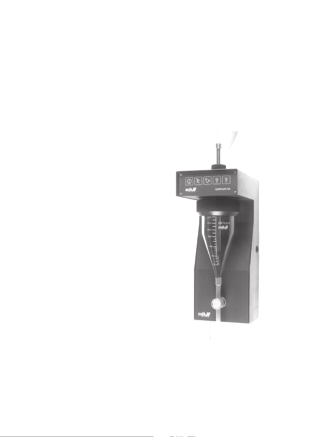
MJK Liquid Sampler 780 is designed to make samples
from lakes, rivers, sewage systems, pumping stations etc. It
can be used in fixed installations or as a portable unit. The
sampler operates from the manual panel, or is controlled
from a flowmeter or a timer.
The sampler can be connected directly to an MJK 713
Ultrasonic flow converter for flow proportional sampling.
The MJK Liquid Sampler 780 consists of 3 modules: a
combined valve / compressor unit, a control panel and a
power supply, all located inside a rugged stainless steel
enclosure. The parts that need to be cleaned are mounted
externally.
OperationOperation
Operation
OperationOperation
MJK Liquid Sampler 780 is operated from the front panel
or can be controlled via external signals from flowmeter,
timer, or MJK Integrator 783. The MJK Liquid Sampler 780
can be connected dirctly to MJK Flowmeter 713 for flow
proportional sampling.
MJK Liquid Sampler 780 uses pressure and vacuum for
sampling. When the sampler receives a start signal from
either the control panel or an external signal, the sample
tube is pressurized to clear residue from the previous
sample. The vacuum remains on until the sample glass is
full. Then the glass is again pressurized to clear the surplus
liquid from leaving the required sample (20 ml to 500 ml) in
the glass.
When the required level is reached, the outlet valve opens
and the sample runs into the collecting container.
MJK Liquid Sampler 780 has a built-in alarm system. If the
sample tube is blocked during the filling of the sample
glass, the alarm operation re-pressurizes the sampler to
clear the obstruction. The cycle then starts again. If the
sample glass is not filled at the second try within a preset
time, the sampler will not be blocked.
The control system of the sampler is in a sturdy design and
is unaffected by electrical noise. The sampler can be
operated manually or controlled from a flowmeter or timer.
Mechanical mountingMechanical mounting
Mechanical mounting
Mechanical mountingMechanical mounting
The sampler should be mounted on a wall or bracket. On
the back of the cabinet there is 2 'keyhole' slots at the top
and a slot at the bottom. Note, that 230 mm free space is
required at the left hand side of the cabinet in order to be
able to open the upper part of the cabinet. The sample
tube is immersed in the channel or the basin where the
sample will be taken from. The outlet tube runs to the
sample container, where the samples are stored until
analysed. The tubes may be extended as required.
Please observe the following when mounting the sampler:
- The sampler must be mounted vertically so the inlet and
outlet can have the most optimum position. Vertical
mounting is required for utilizing the measuring scale on
the sample glass.
- The maximum vacuum capacity of the sampler is 8m WG
(0,8 bar) and is used to lift the sample from an lower
liquid surface, and to overcome pressure loss in the
sample tube.
- The sampler must be mounted so the sample container
can be placed underneath. Under particular
circumstances it can be placed elsewhere, since the
measured sample is forced out of the sample measuring
chamber.
- During the summer months we recommend to avoid
exposing the sample container to the heat of the sun.
- During the winter it will be necessary to protect the
sampler from frost. The sampler is able to function down
to -20° C, since the sampler is drained after every
sample; there is only a minor risk for frost damages. On
the other hand, the sampler must be protected, warmed
and insulated when it is placed outdoors. Consideration
as to air temperature, temperature and size of every
sample as well as how long the samples have to be in
the sample container, must be taken.
However if another cycle is desired , all cycle functions are
located on a terminal block, so the control of the internal
functions and monitoring can be taken over via a PLC or pc.
SpecificationsSpecifications
Specifications
SpecificationsSpecifications
SamplingSampling
Sampling
SamplingSampling
Cycle time: App. 2 min (adjustable to 1 - 10 min)
Amount: 20 ml to 500 ml
Suction height: 0,75 bar abs
Pressure: Max. 1 bar (when flushing the sample hose)
Sample temp.: Max. +60
Environment: –20 - +60
Suction tube: PVC, inner dia. 9,0 mm x 2 m
Outlet tube: Silicone, inner dia. 9,5 mm x 1 m
Mechanical dataMechanical data
Mechanical data
Mechanical dataMechanical data
Housing: Stainless steel
Enclosure: IP 55
Weight: 5 Kg
Dimensions: 165 mm x 410 mm x 235 mm (w x h x d)
Electrical dataElectrical data
Electrical data
Electrical dataElectrical data
Supply: 110/220V AC and 12V DC
Consumption: 30 W during sample, 2 W stand by.
0
C
0
C
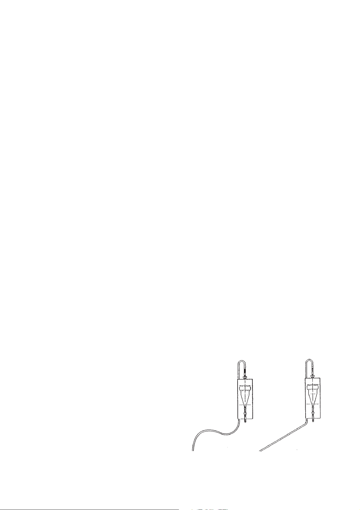
The sample tube must be straight without kinks when the
vacuum cycle begins. (See illustration below).
SAMPLE SAMPLE
TUBE TUBE
WRONG! CORRECT!
2
Page 3
TT
erminalserminals
T
erminals
TT
erminalserminals
The terminals for the electrical connection is found underneath the lid behind the sample glass. The sampler
cabinet is opened with the enclosed cabinet key.
Connect the sampler in accordance with the diagram.
110 - 120V/220 - 240V AC 12VDC
EXT. START EXT. ALARM
RESET
SUPPLY EXT. CONTROL SIGNAL SAMPLE ALARM
ExamplesExamples
Examples
ExamplesExamples
Flow proportional liquid sampling together with MJK Flow Converter 713Flow proportional liquid sampling together with MJK Flow Converter 713
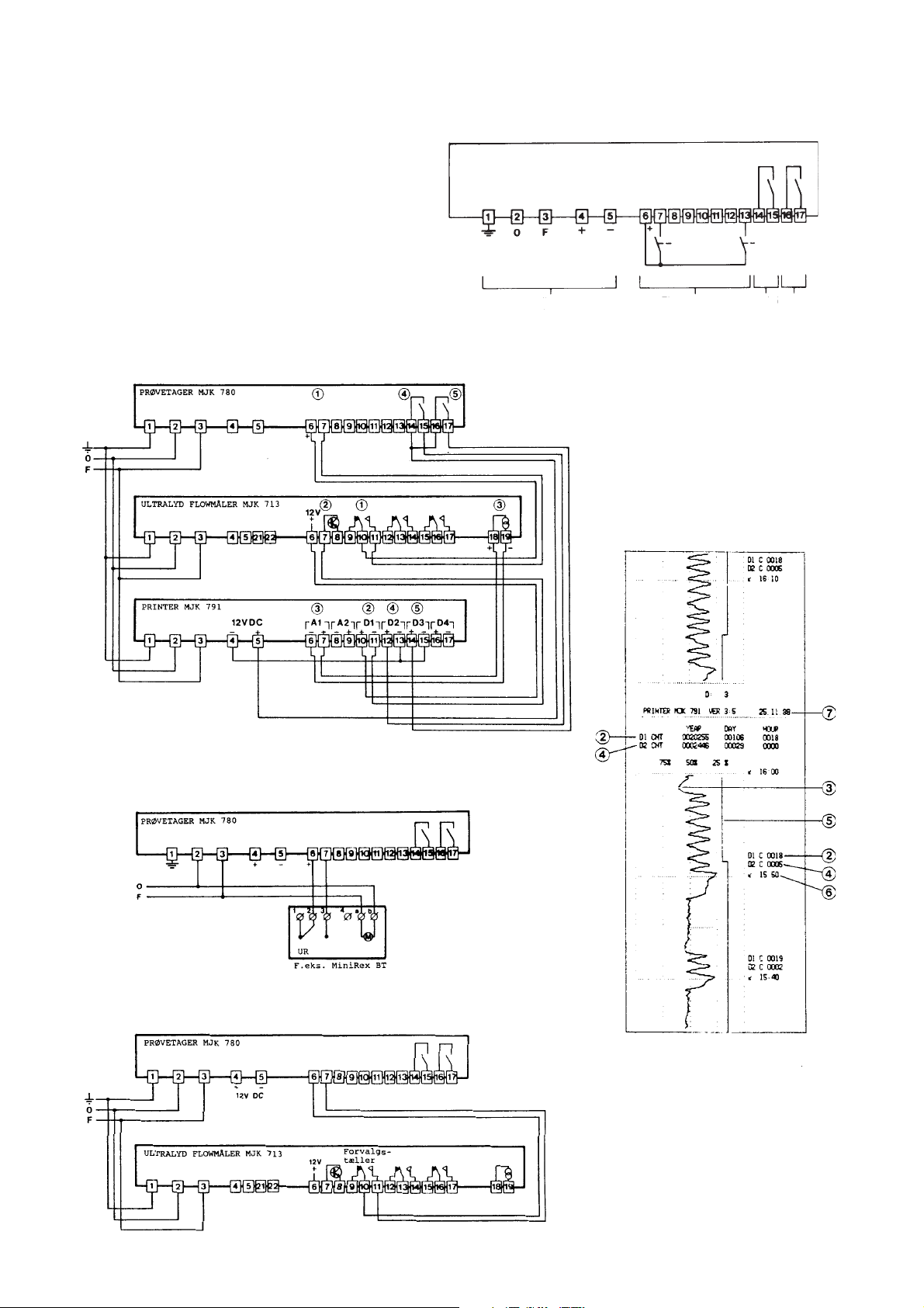
Flow proportional liquid sampling together with MJK Flow Converter 713.
Flow proportional liquid sampling together with MJK Flow Converter 713Flow proportional liquid sampling together with MJK Flow Converter 713
This example show also th econnection of a MJK PRINTER 791 for recording of flow and samlping.
Printout examplePrintout example
Printout example
Printout examplePrintout example
1 Start liquid sampler
2 Totalization of flow
3 Graphic presentation of the flow
4 Sample count
5 Alarm registration from the sampler
6 Time
7 Day - month - year
STO P
Timer controlled liquid samplingTimer controlled liquid sampling
Timer controlled liquid sampling
Timer controlled liquid samplingTimer controlled liquid sampling
Flow proportional liquid samplingFlow proportional liquid sampling
Flow proportional liquid sampling
Flow proportional liquid samplingFlow proportional liquid sampling
3
Page 4

OperationOperation
Operation
OperationOperation
The sampler is operated on the control panel. The symbols
have the following meaning and function.
Pressure indicator
Start/stop of the sampler.
The function is an electrical memory function, so the
chosen position (start or stop) is maintained also after a
power failure. The sampler will continue taking samples or
will stop according to the previous position. The green LED
indicates that the sampler is on and ready (stand by) when
a start signal occurs.
Manuel sampling.
By depressing the start key, a sample cycle is started. This
function is always active and can be used alone or together
with an external control signal. The green LED indicates
that the sampler is in operation.
Alarm (reset).
This LED (green) indicates that the compressor has
pressurized the sample glass in order to:
* to purge out the previous sample from the sample tube.
* to purge out excess liquid during adjustment of the
sample volume.
* to flush the set sample volume into the sample can.
Vacuum indicator.
This LED (green) indicates that there is vacuum in the
sample glass when
* the sampler pulls up the sample in the sample glass.
Start-upStart-up
Start-up
Start-upStart-up
When the sampler is mounted and electrical connections
completed, the sampler is ready for start-up.
Ensure that the sample tube is immersed in the channel or
basin where the sample will be taken. Position the outlet
tube so that it reaches the sample container.
Adjust the sample volume from 20 ml – 0,5 l. The
adjustment is made by loosen the nut and pushing the
measuring pipe until the lower edge of the pipe is on the
level with the line on the sample glass, which corresponds
to the desired flow.
The ALARM key resets the sample cycle.When there is an
alarm, the light diode flashes (yellow), as described in
section 9. It continues to flash until the key is activated to
reset the alarm.
Sample cycleSample cycle
Sample cycle
Sample cycleSample cycle
The sample sequence is presented below:
Function: Purge Suction Volume adjustment Sample pump out Purge
Signal: –––––T 1––––– ––––Level–––– –––––T 2––––– –––––T 3––––– ––––T 1–––––
Compressor: xxxxxxxxxxxxxxxxxxxxxxxxxxxxxxxxxxxxxxxxxxxxxxxxxxxxxxxxxxxxxxxxxxxxxxxxxxxxxx
Pressure xxxxxxxxxxxxxx xxxxxxxxxxxxxxxxxxxxxxxxxxxxxxxxxxxxxxxxxxxxx
Vacuum xxxxxxxxxxxxxxx
Level detection x
Outlet valve open xxxxxxxxxxxxxx
Alarm –––––––T 4––––––––
Connect the power supply when the measuring pipe has
been adjusted to the correct height. The ON/OFF key
activates the green diode light and the sampler is ready for
start (standby) when the “Start” key is pressed.
When the sampler is started, the green diode light will light.
During operation the compressor will be audible. The green
diode lights in the symbols for pressure and the vacuum,
indicate the internal valves are controlling the compressor.
(outlet to sample can)
4
Page 5
As shown in the diagram, the compressor starts when the
sampler is started. When starting, the valves are switched
out to put pressure on the sample glass, to remove any
previous sample. The purge time is determined by the
timer T1 (purge).
When time T1 has elapsed, the valves switch to create a
vacuum. The sample glass and the water will be pulled into
the sample glass, until the level electrodes are activated.
When the level electrodes have been activated, the valves
are switched over again, to put pressure on the sample
glass. Excess sample will be blown back in the sample
tube. Pressure continues until the time, determined by the
timer T2 has elapsed.
The outlet valve opens under pressure and the sample is
dropped into the sample container. The outlet valve
remains open for time T3 (purge).
It is possible to switch off the last purge by cutting off the
connection “Purge“ 2.
The sequence contains an alarm, which activates if the
sample does not contact the electrodes by a preset time
T4 (alarm). This alarm protects the sampler from continuous
cycles caused by blockage. However since the
compressor creates a 4 bar pressure, it is not very likely
that blockage will occur.
There are no dangerous voltages present at the control
unit, so it can be touched during operation. When the
desired adjustment has been made, depress (“ON/OFF”
key) to avoid short circuit during mounting, and the control
unit attachment.
External sequenceExternal sequence
External sequence
External sequenceExternal sequence
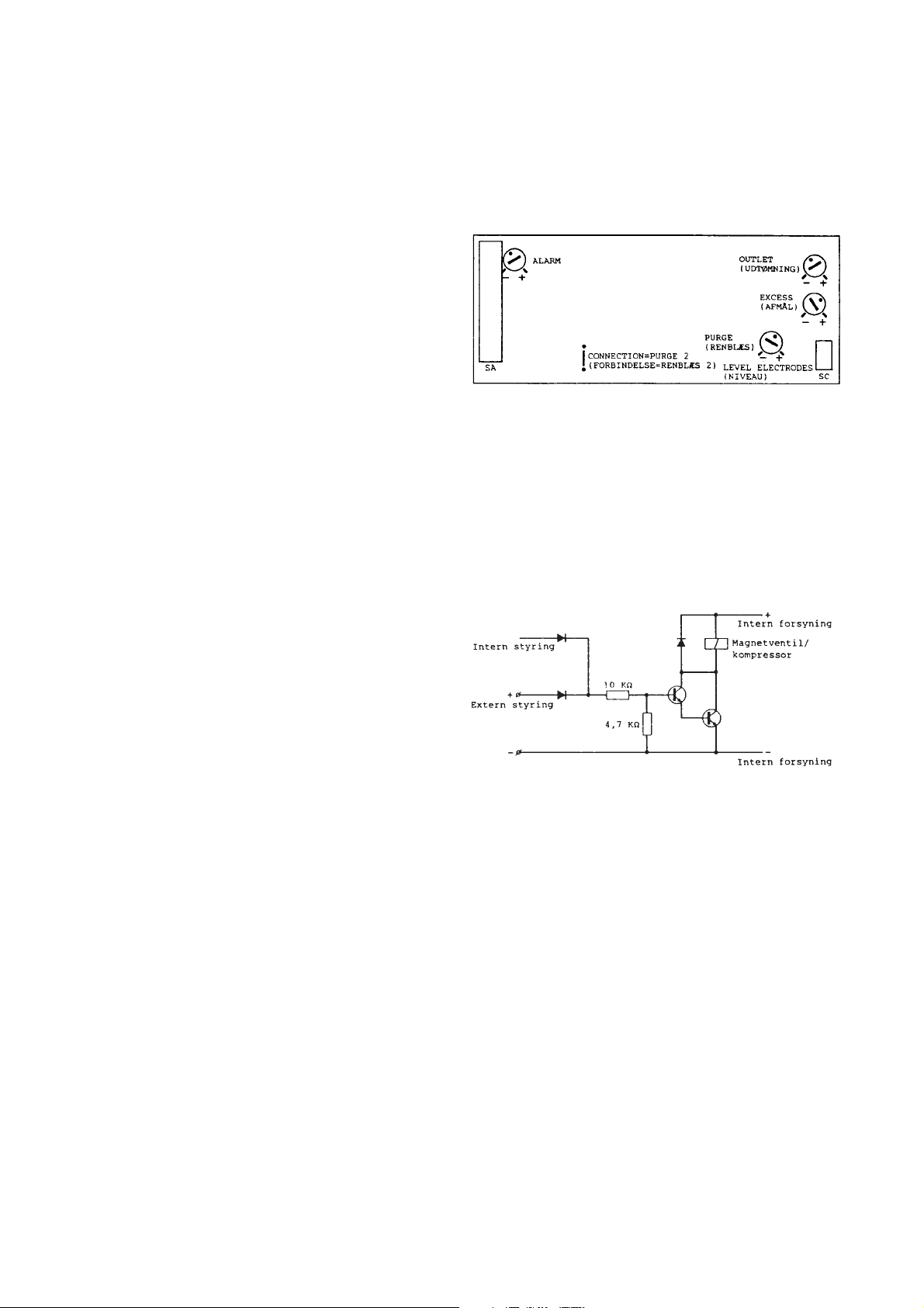
The sampler can be controlled externally, e.g. from a PLC.
When an external control is connected, it works in parallel
with the internal control, so that it is possible to select a
manual sample controlled by the internal system of the
sampler, at the same time as the external control.
The inputs are semi-conductor inputs as indicated at the
diagram.
If the sampler does not succeed to activate the level
electrodes the second time before the time T4 has run out,
the sampler will stop and prevent further starts. To indicate
the alarm, the yellow alarm flashes and the alarm relay is
activated. To make the sampler start again, the alarm state
has to be reset by activating the “alarm” key.
Setting of sequence timesSetting of sequence times
Setting of sequence times
Setting of sequence timesSetting of sequence times
The sequence time is factory adjusted, to a total sample
time of approx. 2 minutes.
The 4 timers have the following time ranges:
Timer (function)Timer (function)
Timer (function)
Timer (function)Timer (function)
Purge T 1: 30 - 150 sec 30 sec
Volume T 2: 30 - 150 sec 30 sec
adjustment
Outlet T 3: 30 - 150 sec 30 sec
(outlet)
Alarm T 4: 30 - 150 sec 60 sec
The sequence times are adjusted with the potentiometers
on the back of the control unit. To adjust the time, the
control unit must be removed. Switch off the sampler (ON/
OFF) key and unscrew the 4 screws, which hold the front
panel to the control panel. The control unit is integral with
the front panel. When the control unit has been removed
the sampler can be started again and the adjustment
made.
RangeRange
Range
RangeRange
Factory settingFactory setting
Factory setting
Factory settingFactory setting
The input signal should be not activated <0,5 V DC
Activated 5-24 V DC.
5
Page 6
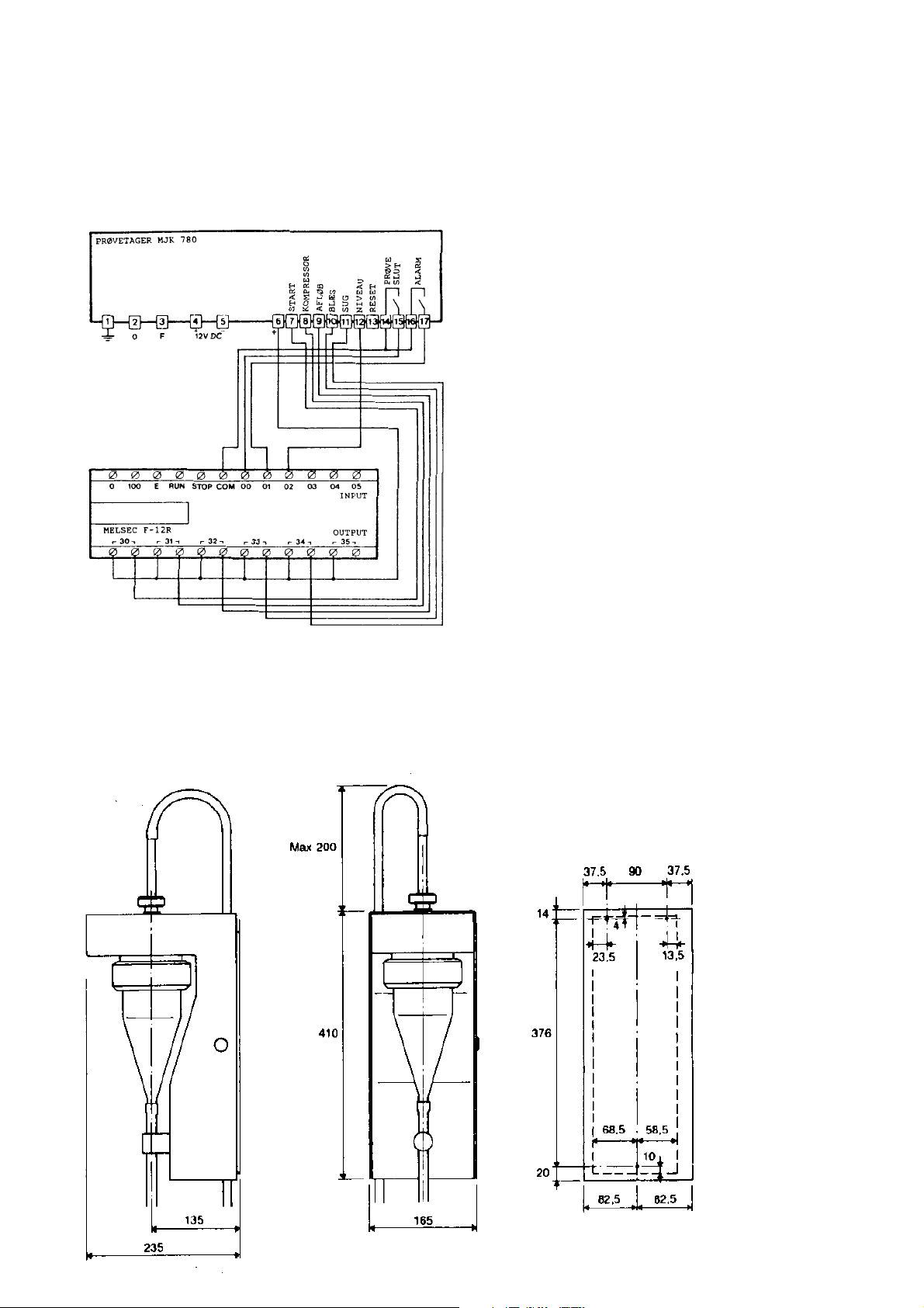
Example of PLC controlled sampleExample of PLC controlled sample
Example of PLC controlled sample
Example of PLC controlled sampleExample of PLC controlled sample
The sampler is connected to a PLC. In the example a
MITSUBISHI MELSEC F-12R is displayed, but any PLC can
be used.
MiscellaneousMiscellaneous
Miscellaneous
MiscellaneousMiscellaneous
MaintenanceMaintenance
Maintenance
MaintenanceMaintenance
The sampler must be kept clean of dirt on the following
points:
* The sampler glass must be kept clean on the inside
* The level electrodes in the top of the sample glass must
be cleaned
* The sample tube and the outlet tube must be cleaned
How often the cleaning is necessary, depends on how often
the sampler is used. In municipal sewage plant, we
recommend monthly cleansing, where the sampler tube is
put in a bucket with 10% diluted hydrochloric acid.
Hydrochloric acid is a degreaser and cleans grease and
sludge from all inside surfaes.
Start the sampler 2-5 times dependent on how much
coating there is on the inside surfaces.
The plastic house inside between the electrodes should be
cleaned.
The outlet tube should be removed during cleaning.
Spare partsSpare parts
Spare parts
Spare partsSpare parts
Item nr.:Item nr.:
Item nr.:
Item nr.:Item nr.:
Complete unitsComplete units
Complete units
Complete unitsComplete units
803510 control unit complete with front panel
803515 Power supply unit
813510 Valve / pumping unit
Description:Description:
Description:
Description:Description:
115/230V AC and 12V DC
Other partsOther parts
Other parts
Other partsOther parts
595120 Suction hose, PVC, dia. 9,0mm.
Specify length.
595121 Discharge hose, Silicone, dia. 9,5mm,
Specify length.
595110 Sample glass
570025 O ring for sample glass, silicone,
dia. 75mm x 8mm
570027 O ring for measuring pipe, nitril, dia. 10 x 3mm
Dimensions Dimensions
Dimensions
Dimensions Dimensions
6
 Loading...