

Page 1
Manual
Flow Converter 713
GB Flow Converter 713 0704
Page 2

Table of Contents
Page
Flow Converter 713 3
Technical section 3
Rectangular sharp edged weir 3
Triangular Weir 4
Parshall Flumes 5
Palmer & Bowlus Flumes 6
Venturi umes 7
Mounting of Sensor 8
Electrical Connection 8
Cable extensions 9
Ultrasonic sensor color codes 9
Cutting the cable 9
Control 10
Function keys 11
Flow key 11
Summation key 11
Alarm key 12
Sample key 13
Menu key 13
Conguring 14
Specications 17
Order numbers 17
Dimensions 17
Functional indications 18
Menues for conguring 19
Settings for the ow converter 20
CE - CERTIFICATE OF CONFORMITY
This product complies with the requirements concerning electromagnetic compatibility (EMC) stipulated in Council directive no.
89/336/EEC of 3rd May 1989, altered at directive no. 92/31/EEC,
on the approximation of the laws of the Member States relating to
electromagnetic compatibility.
MJK Automation A/S declare that the product complies to the
values stipulated in EN 50081-1 and EN 50082-1.
2
Page 3
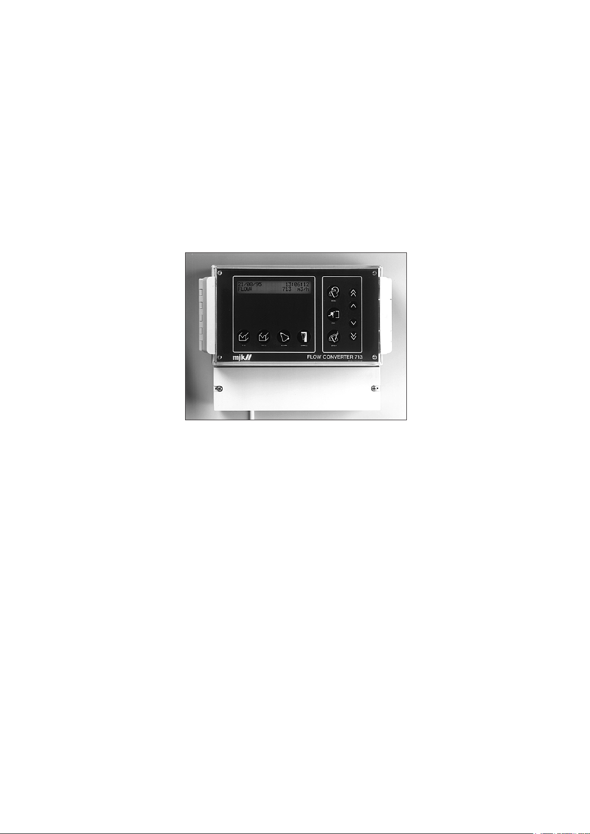
Flow converter 713
Thank you for choosing Flow converter 713. Flow converter 713 is a modern construction, in which the relation
between functions, and "userfriendliness“ and precision
is optimum. In order to gain full use from the equipment,
we recommend that you read the instructions very thoroughly. Should any problems occur during installation or
operation, our technicians will be at your disposal.
Flow converter 713 is for the measurement of ow in
open umes and weirs. The method of measurement
and linearization complies with the norm ISO 1438. This
norm indicates how the head over the weir and umes
are constructed, and how the calculations for linearization are to be arrived at. The owrate is generaly speeking determined by using the following mathematical
function:
Flow Q = f(level
x
· constant)
where the exponent x and the constant depends on the
weir or the ume.
The ow converter has 3 different linearization systems
depending on how the volume of water is measured.
• One choose between a number of predened umes and
weirs, e.g. Parshall umes and V-notch weirs.
• If the ume or weir differ from the normal types of umes
and weirs, the formula Q(h)=k x hn can be applied, where
k and n are keyed in directly.
• Some times it can be desirable to linearizate a levelsignal
which does not follow a mathematical expression. As an
example a ow can be measured in a partly lled pipe,
where the menu point-linearization can be applied.
Technical section with the principles of measuring
Flowconverter 713 converts the level to ow from these
examples. Some of the examples are simplied. The ISO
1438 norm indicates a number af calculation methods
for umes and weirs. The Flowconverter 713 uses these
methods where it is possible.
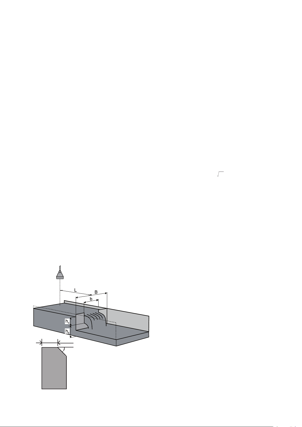
Rectangular sharp edged weir
according to ISO 1438
Rectangular sharp edged weir is supplied in two types:
- with side contraction
where the opening has a smaller width than the feeder
and
- without side contraction
where the width of the opening corresponds to the width
of the channel (B = b).
Rectangular sharp edged weir
with side contraction:
Universal formula: (Kindsvater/Carter)
Q = 3600 × Ce × 2/3 × 2g × be × h
where: Q = ow in m3/h
b = width of weir in [m]
be = effective width of weir in [m]
be = b + k
ha = height in [m]
b
he = effective height in [m]
he = ha+kh, kh = 0,001
hb = depth below edge in [m]
B = ume width in [m]
L = distance to sensor,
4 - 5 × h
g = acc. due to gravity = 9,81 m/s2
a max.
kb is a correction factor in meter.
For determination of k
b/B = 0 kb = 0,0024 m
b/B = 0,2 kb = 0,0024 m
b
b/B = 0,4 kb = 0,0027 m
b/B = 0,6 kb = 0,0036 m
b/B = 0,8 kb = 0,0042 m
b/B = 1,0 kb = -0,0090 m
1,5
e
d
β
ß = minimum 45°
d ~ 1-2 mm
Edge
Ce is a contraction coefcient (no unit) depending on the
ratio of b/B and ha/h
b.
For determination of Ce
b/B = 1,0 Ce = 0,602+0,075 ha/h
b/B = 0,9 Ce = 0,598+0,064 ha/h
b/B = 0,8 Ce = 0,596+0,045 ha/h
b/B = 0,7 Ce = 0,594+0,030 ha/h
b/B = 0,6 Ce = 0,593+0,018 ha/h
b/B = 0,4 Ce = 0,591+0,0058 ha/h
b/B = 0,2 Ce = 0,588-0,0018 ha/h
b/B = 0 Ce = 0,587-0,0023 ha/h
b
b
b
b
b
b
b
b
3
Page 4
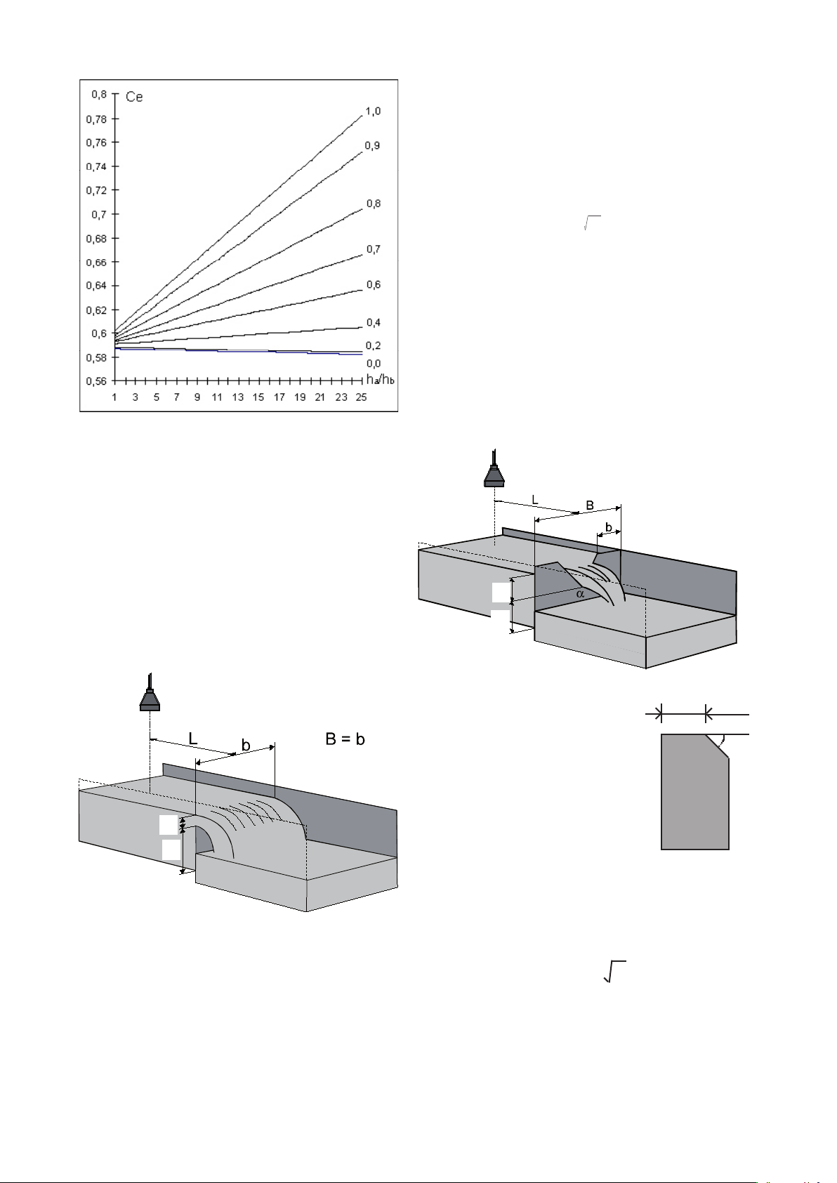
The following limitations apply for the values of ha/hb, ha,
hb and b:
ha/hb = max. 1,0
ha = min 0,03, max 0,75 m
hb = min 0,10 m
b = min 0,30 m
Formula: (Rehbock equation)
Determination of Ce for different values of b/B.
The following limitations apply for the values of ha/hb, ha,
hb and b:
ha/hb = max. 2,5
h
h
b = min 0,15 m
a
b
= min 0,03 m
= min 0,10 m
(B-b)/2 = min 0,10 m
Rectangular sharp edged weir without side
contraction:
Q = 3600 × Ce × 2/3 × 2g × b × h
where: Q = ow in m3/h
b = width of edge in [m]
Ce = 0,602+0,083 ha/h
ha = height in [m]
b
he = effective height in [m]
he = ha+kh, kh = 0,0012
g = acc. due to gravity = 9,81 m/s
Triangular weir
according to ISO 1438
h
a
h
b
1,5
e
2
h
a
h
b
The sides of the channel must continue at minimum 0,3
x h
after the weir.
a max.
ha = height
hb = depth below edge in [m]
B = ume width in [m]
L = distance to sensor,
4 to 5 × h
a max.
ß = minimum 45°
d = 1-2 mm
d
ha = height in [m]
hb = depth below edge in [m]
B = umewidth in [m]
L = distance to sensor,
4 to 5 × h
a max.
The following limitations apply:
α = 20° - 100°
ha/hb = max 0,4
ha/B = max 0,2
ha = min 0,06 m
hb = min 0,09 m
Formula: (Kindsvater-Shen).
Q = 3600 × Ce × 8/15 × 2g × tg(α/2) × h
where: Q = ow in m3/h
ha = height in [m]
he = the effective height in [m]
he = ha + kh, kh = 0,001
g = acc. due to gravity = 9,81 m/s
2
α = aperture angle
β
2,5
e
4
Page 5

kh is set to 0,001 m and is a correction factor.
The ow is calculated from the formula:
Ce is the coefcient of discharge (no unit). For determi-
nation of Ce, look at diagram below.
0,005
0,004
0,003
0,002
0,001
Diagram for determination of k
h
Diagram for determination of Ce.
Q = k × h
n
where:
a
Q = ow in m3/h
b = width in the measuring ume in[ m]
ha = water level before the narrowing in [m]
hb = water level in the narrowing in [m]
L = distance to the sensor (use table below)
The factor k and exponent n are constants.
The formula complies to free ow, hb
< 0,7 × h
max
a max
b k n L
1" 217 1,548 0,24
2" 425 1,548 0,27
3" 630 1,548 0,30
6" 1310 1,574 0,41
9" 1851 1,528 0,58
12" 2407 1,519 0,89
24" 5142 1,55 0,99
36" 7863 1,566 1,09
Table for determination of the constants k, n and the
distance to the sensor.
12"
36"
9"
6"
3"
2"
1"
24"
Parshall ume
The most common type of ume is the Parshall ume.
The Parshall ume is a standardized Venturi ume.
h
a
h
b
At free ow, only the level ha is measured. The location
of the sensor is important and must be carried out as illustrated in the drawing and the table in the next column.
It is important to have a laminar ow (horizontal streaming calm water with no whirls) at the out- and inlet from
the ume. Upstream the measuring ume, must extend
at least ten times the width of the inlet section of the
ume.
On the outlet side the only demand is that the water
should run freely. This is the case when hb ≤ 0,7 × ha.
Q/h diagram for Parshall umes, the height ha is shown
as a function of the ow Q.
5
Page 6
Ark6 Diagram 1
0
0,05
0,1
0,15
0,2
0,25
0,3
0,35
0 50 100 150 200 250 300 350 400 450 500
8"
10"
12"
15"
24"
30"
Q [m3/h]
h
a
[m]
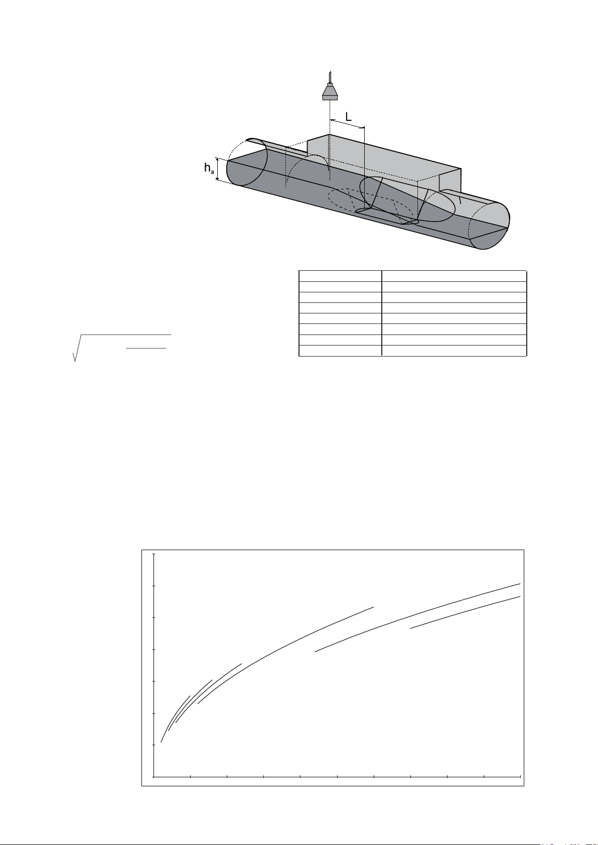
Palmer - Bowlus ume
The Palmer & Bowlus ume is characterized by its circular connection, which makes it easy to install in pipe-
lines. The ume is aimed at measurement in the scale of
20-100% of the prescribed ow.
where:
ha = water level before the narrowing
L = ½ × DN (the nominal diameter of the ume),
measured from the beginning of the meas. section.
No simple ow formulas can be set up for the Palmer
& Bowlus umes, the formulas are dened individually
for every ume. The Flow formulas are derived from the
continuity equation and Bernoulli’s equation:
2
2
A
x A
1
Q = 2g(h1- h2) x
where:
A1 and h1= cross section and height in the inlet of the
ume
2
2
2
A
- A
1
2
Size D Max Flow
6'' (DN 150) 35 m3/h
8'' (DN 200) 70 m3/h
10'' (DN 250) 110 m3/h
12'' (DN 315) 200 m3/h
15'' (DN 400) 325 m3/h
18'' (DN 450) 545 m
3
/h
24'' (DN 600) 1100 m3/h
30'' (DN 800) 1750 m3/h
Table showing the size of D, and the max. ow for the
Palmer & Bowlus umes.
A2 and h2= cross section and height in the outlet of the
ume
For the Palmer & Bowlus umes with the dimensions 6'',
8", 10", 12", 15", 18'', 21'', 24" and 30", the ow formulas
are dened and incorporated in the ow converter. In
the menu „Programming of ow calculation“ the relevant
ume is chosen.
Q/h diagram for the MJK Palmer & Bowlus umes, the
height ha is shown as a function of the ow Q.
6
Page 7

Venturi ume - long throated
according to ISO 1438
The following formula and diagram concern the long
throated Venturi ume.
Venturi ume - Khafagi
The following formula and diagram concern the Khafagi
Venturi ume.
L
b
h
a
713 follows the calculation method for long throated
Venturi umes described in ISO 1438. The connection between level and ow is complex and can not be
described in a simple formula. When dimensioning the
following simplied formula can be applied.
Q = 6495 x b x h
where:Q = ow in [m3/h]
b = width in the ume in [m]
ha = water level before the narrowing
L = distance to the sensor = 3 - 4 x h
1,5
(NB: not ISO 1438!)
a
a max
L
h
a
b
The ow is calculated from the following formula.
Q = 6278 x b x h
1,5
+ 328 x h
a
2,5
a
where:Q = ow in [m3/h]
b = width in the ume in [m]
ha = level
L = distance to sensor = 3 - 4 x h
H = height of the ume
a max
160mm
120mm
H
200mm
200mm
160mm
120mm
Q/h diagram for the long throated Venturi umes,
the height ha is shown as a function of the ow Q.
Q/h diagram for the Khafagi Venturi umes, the
height ha is shown as a function of the ow Q.
Size b H Max Flow
5" (DN 120) 150 mm 35 m3/h
5'' (DN 120) 300 mm 120 m3/h
6'' (DN 160) 300 mm 150 m3/h
8'' (DN 200) 320 mm 200 m3/h
8'' (DN 200) 520 mm 450 m3/h
Table showing the size of b, and max. ow for the
Venturi ume - Khafagi.
7
Page 8

Mounting of sensor
Ultrasonic measuring system
The Ultrasonic sensor must be placed correctly according to the actual
measuring stormows. The sensor has to be installed at right angles
above the liquid surface (level tube). We recommend using bracket
type MJK 200270, and if necessary it can be used together with universal brackets of type MJK 200205.
The following distances ensure a correct function:
Measuring range 0-30 cm 0-1 m 0-3 m
Blocking distance 40 cm 40 cm 75 cm
Min. meas. range 10 cm 10 cm 30 cm
Max. meas. range 30 cm 1 m 3 m
Max. sensor height 70 cm 140 cm 3,75 m
When measuring stormows, it might be necessary to mount a reection plate, within the measuring range, to ensure that the echo signals
are returned. E.g. if the distance at low levels exceeds the maximal
sensor height.
The distance from the reection plane to the 0-level of the measuring (=
normally the height of the weir) is set as the 0-level suppression. Notice
that the 0-level suppression must be added to the measuring range, to
respect the maximal sensor height
The following always applies to ultrasonic measuring systems:
Maximal sensor height = blockingdistance + measuring range +
optional 0-level suppression
Hydrostatisc measuring system
The pressure transmitter must be placed correctly according to actual
measuring stormows. The sensor must be fasted possibly mounted
on a pipe with a 1 inch. internal screw thread. In some case it might be
necessary to mount the pressure transmitter in a measuring well, so the
transmitter will not effect current of water.
The following distances ensures a correct function:
Without 0-level suppression - recommended at
normal ow measuring in
umes and weirs
Blocking
distance
Measur-
ing-
range
Sensor height
With 0-level suppression -
recommended at stormow
measurings
Blocking
distance
Opt. reflection plate
Measuring
range
0-level
suppression
Sensor height
Recommended at ow- and
stormow measurings
Measuring range 0-30 cm 0-1 m 0-3 m
Measuring range
Min. range 10 cm 30 cm 1 m
Max. range 30 cm 100 cm 3 m
The following always applies to hydrostatic measuring systems:
Maximal sensor height = measuring range + optional 0-level suppression
Notice that the 0-level suppression must be added to the measuring
range.
Measuring range
0-level suppression
Electrical connection
Electrical connection of the Flow Converter 713, for hydrostatical, and ultrasonic measurement systems respectively.
Flow Converter 713
Hydrostatic measuring
system
Supply
Hydrostatic sensor 7062
Flow Converter 713
4-20 mA supplied
Supply
Flow Converter 713
Ultrasonic measuring
system
Supply
Level Transmitter 511U
4-20 mA output signal
+ -
Relais 1 to 4 Puls output Analog
output
Ultrasonic sensor 7005
An example of an installation, with long distance
(more than 50 m) between the measuring location
and the amplier. A MJK 511 Level transmitter (with
a 3-wire, 4-20 mA supply) is applied as preamplier,
and the signal is transmitted via an ordinary 3-wire
cable. The 511 level transmitteren is set for 100%
measuring range, this allows any adjusting of the
measuring range to be carried out from the owconverter. This mounting allows you to have a distan-ce
8
between sensor and amplier of more than 1000 m.
Page 9

Cable extensions
One of the most common faults on a MJK 713 installation is bad or faulty cable connections.
It is recommended to use a MJK connection box if the
sensor cable must be extended.
Ultrasonic sensor color codes
The ultrasonic sensor are standard delivered with 40 ft
of cable. The ultrasonic sensor can be delivered with up
to 150 ft of cable on order, or the standard 40 ft cable
can be extended to max. 150 ft.
The cable is a special low capacity cable,
so extensions should always be made with
the same type of cable.
MJK Connection
Box (NEMA 4X),
order no.
200590.
Cutting the cable
The cable is delivered with the wires stripped as shown
with the black wire (no. 5) soldered to the shield:
When the cable is cut, only 4 wires will appear:
To ultrasonic
sensor
Max. 150 ft.
To MJK 713
flow meter
The ultrasonic sensor cable has 5 wires with both color
code and number:
Number Color Designation
1 Brown Ultrasonic pulse
2 Red Ultrasonic pulse
3 Orange Temperature compensation
4 Yellow Temperature compensation
5 Black Shield *)
*) This wire is connected to the cable shield.
The wires are mounted according to the terminal markings on the connection box PCB and on the MJK 713
respectively.
When the cable has been cut, the shield
should be mounted in terminal 5 instead
of the black wire !
9
Page 10

Control
On the front of the Flow Converter, you will nd 4 function keys: the ow key, the summation key, the alarm key
and the sample key.
When one of these keys are pressed once or more the
different function menues appear. The avaliable menus
depend on how the Flow Converter is congured.
The conguring of the Flow Converter takes place in the
conguring menus, which in turn is divided into several
submenus. You gain access to the conguring menus by
pressing the MENU key. In each menu the different settings are obtained by pressing the arrow keys.
A complete diagram of the menus can be found on page
17 in this manual.
On the following pages every submenu is described.
The figure below shows the genel function of the key on
the Flow Converter:
Display
2 x 24 characters text display for indication of menus
and values. The background
of the display is illuminated.
Q(t)
Registers for flow:
- Instantaneous value
- Average flow 1 hour
- Average flow i day
- Average flow 24 hours
The ESCape-key
The key will change back to
the head menu, or undo a
new choice. By pressing the
ESC.-button two or three
MENU
By activating the MENUkey, the display will change
to the next head menu in
the outline of the menu.
times you will always return
to the indication of functions.
ALARM
Alarm record with the previous
nine alarms incl. date and time
of occurance.
As well as time for voltage
coupling.
Σ Q(t)
Registers for either: or:
- Summed flow total - Number of stormflows
- Summed flow 1 hour - Time of stormflow
- Summed flow today - Total stormflow
- Summed flow 24 hours - Amount of most recent stormflow
- 99 days log - Start/finish time for last
stormflow
10
The arrow keys
The arrow keys are used
for changing a current
setting. An arrow key is
pressed to change between a current and not
current setting. Activating
of the arrow keys also
changes the values. By
activating the
↑-key, the number in
the display will increase.
When activating the ↓-key
the value decreases.
ENTER
A shift from the
head menu to
submenu, as
well as between
submenus is
carried out by
activating the
ENTER-key. A
choice from a
submenu also
needs confirming
by pressing the
ENTER-key.
SAMPLER
Registration of:
- Total number of samples
- Number of samples today
- Number of samples within
24 hours
Page 11

Function keys
Flow key
Q(t)
This key gives access to a number of menues that dis-
playes the values of the current ow, as well as various
average values.
F1 Flow
Press once for:
21/06/95 13:34:12
FLOW : 3196 m3/h
The instantaneous current ow is shown. The ow is calculated from the chosen Q(h)-formula. Measuring value
with time and date is indicated.
F2 Average ow 1 HR
Press twice for:
AVERAGE FLOW: 1 HR
FLOW : 3120 m3/h
The summation key
Σ Q(t)
If the ow converter is set up for continuous measuring,
this key will give access to indication of summed quanti-
ties. If the ow converter is set up for stormow measuring the stormow quantities and number of stormows
are indicated.
Measuring of volume
F5 Σ volume
Press once for:
21/06/95 13:34:12
Σ VOLUME: 223196 m
The total volume is indicated, from when the value was
last reset or since start-up.
F6 Σ volume 1 HR
3
The average ow for the last full hour is indicated.
F3 Average ow today
Press three times for:
AVERAGE FLOW: TODAY
FLOW : 3120 m3/h
The average ow from 00:00:00 to the current time is
indicated.
F4 Average ow 24 HR
Press four times for:
AVERAGE FLOW : 24 HR
FLOW : 3120 m3/h
The average ow for the last 24 hours is indicated
(00:00:00 til 23:59:59).
Press twice for:
1 HR 11:00 - 12:00
Σ VOLUME : 77376 m
Here the summed volume for the previous full hour is
indicated (e.g. 14.00-15.00).
3
F7 Σ volume today
Press three times for:
TODAY 00:00 - 13:51
Σ VOLUME: 776 m
The summed volume for today is indicated. The result
along with the time interval is updated every full minute
(xx:xx:00).
3
F8 Σ volume 24 HR
Press four times for:
24 HR : 21/05/95
Σ VOLUME: 77376 m
3
The summed volume for the previous 99 days is indicated. The daily quantity is logged every day at (00:00:00).
Use the arrowkeys to browse through the last 99 days
log.
Quantity values can be reset by pressing ENTER, see
menu F19.
11
Page 12

Stormow measuring
F9 No. of stormows
Press once for:
Alarmkey
21/06/95 13:34:12
NO. OF STORMFLOWS 19621
The total number of stormows is calculated from the last
time the value was reset or the system was restarted.
F10 Stormow time
Press twice for:
21/06/95 13:34:12
STORMFLOW TIME : 00:21
Here the total time (hours:minutes) of stormow is indicated.
F11 Stormow volume total
Press three times for
STORMFLOW VOLUME
TOTAL : 1084 m
The total volume of stormows is indicated. The volume
is calculated from the last time the value was reset or the
system was restarted.
3
F12 Volume last stormow
Press four times for:
STORMFLOW
LAST STORMFLOW : 1084 m
The volume of the last stormow is displayed.
3
F13 Stormow start/stop
Press ve times for:
ALARM
The digital outputs can be congured as alarms of one
of the following alarm types: high ow, low ow, 24 hour
volume, one hour volume and sensor error. Press the
alarm key to see the previous nine alarms. A new alarm
is registered as alarm no 1, the other alarms are moved
one place, and the alarm which was previously regis-
tered as alarm no 9 is erased.
F15 Alarm display
After pressing the key once alarm no. 1 is shown, which
is the latest alarm; press again and alarms 2-9 come up.
By using the arrow keys it is possible to move back-
wards and forwards between the alarms.
The instant an alarm is registered, the alarm type, the
digital output and the time shows on the display:
ALARM 1: HIGH FLOW D#
13/03 23:33
When the alarm is no longer active, the time of switch
off is registered. Beware that different alarms could have
been activated in the meantime, meaning the alarm is no
longer no. 1:
ALARM 2: HIGH FLOW D#
13/03 23:33 13/03 23:54
ALARM 3: VOLTAGE FAILURE
21/06 00:22 21/06 11:23
When a new alarm appears the display will change from
the previous chosen main menu to F14 - alarm indica-
tion, alarm 1.
START 25/12 12:32
STOP 25/12 13:01 00:29
Start and stop times are indicated as well as the duration
of the last stormow. All values can be reset by pressing
ENTER, see under F18.
F14 99 days log
Press six times for:
log 12 138 m
The last 99 stormows is saved in a log. Use the arrowkeys to browse through the log.
18/6 12:56 18´/6 14:21
3
The start time for voltage failure is detected every 5 min.,
and the stop time is registered immediately after the volt-
age is cennected again.
12
Page 13

Sample key
Menu key
SAMPLE
If one or several of the digital outputs are congured for
controlling a sampler, pressing this key will give following
indications:
F16 Number of samples
Press once for:
22/02/95 04:39:12
NUMBER OF SAMPLES: 34245
This display indicates how many samples have been
taken since last reset or system start up. Press ENTER
for reset, see menu F19.
F17 Number of samples today
Press twice for:
TODAY 00:00 - 17:22
NUMBER OF SAMPLES: 45
MENU
This key allows access to the menus with reading and
programming of the readings and functions of the ow
converter. In menus with various options the choices will
be seen on top of one another, the top choice being the
current value. By pressing one arrow (up or down) the
choice varies. A choice is conrmed by pressing ENTER.
Non conrmed choices will ash on the display, where
as a current/conrmed choice stands rm.
0.1 Level
Press once for:
LEVEL= 543.2 I= 12.3 mA
D1=0 D2=0 D3=1 D4=1 D5=0
Here the measured level (LEVEL), the value for the
analog output (I) is indicated. The digital outputs are indicated as D1-D5. 0 indicates non activated output, where
as 1 indicates activated outputs. Outputs chosen to "not
in use" are not shown.
0.2 Language
Press twice for:
This display indicates how many samples have been
taken within 24 hours (00:00:00 - now).
F18 Number of samples 24 HR
Press three times for:
24 HR : 30/06/95
NUMBER OF SAMPLES: 11
This menu indicates how many samples were taken
yesterday. Value and date for the previous 24 hours are
indicated.
F19 Reset value
Reset is possible from the menues F5, F6, F7, F9, F10,
F11. By using the enter key and the following menu will
appear:
RESET type
YES: Enter NO: Menu
LANGUAGE ENGLISH
DANSK
By pressing arrows the languages can be altered. When
changing to a new language the display will be clear for
a few seconds.
0.3 Enter access code
Press three times for:
KEY IN ACCESS CODE
USE ARROW KEYS 0000
This menu shows, when an access code has been cho-
sen (four gures) in the conguring menus. Double arrows changes the rst two digits, single arrows changes
the last two digits. Press ENTER for conrmation of
choice of access key. When the access code is correctly
keyed in access to the conguring menus will be given
for 5 min. since last key pressed.
0.4 Access denied
What happens when the wrong access code is keyed in:
ACCESS DENIED
It will not be possible to make changes in the set up. Return to the previous chosen functional menu by pressing
the ESC-key once.
13
Page 14

Conguring
2.1 Sensor and range
1.0 Programming of main functions
Press Enter to obtain access to the conguring menues.
1.1 Set date and time
Time and date is adjusted with the arrow keys, followed
by ENTER, if no change is desired, press the MENU key.
1.2 Access code enabled/disabled
Choose whether access code is desired or not. The
code blocks the access to the conguring menus, but
allows reading and operation of the ow converter. Use
the arrow keys to change between options and conrm
with ENTER.
1.3 Enter new access code
This menu shows a chosen access code (4 gures) on
the conguring menus. The arrow keys are used for
keying in the code as well as for conguring. Double arrows changes the rst two digits, single arrows changes
the last two digits. Press ENTER to conrm choice of
access codes.
1.4 Measurement Stormow /
Continuous
In this menu a choice can be made of whether the ow
converter measures a continous ow or a stormow. Use
the arrow keys to change between choices and conrm
with ENTER.
1.5 Calc. for stormow delayed
In this menu a delay of the level reading is chosen, in order to ensure that the level is over the setpoint for a certain time before the calculation begins. This time interval
is keyed in with the arrow keys. Double arrow shows a
rapid reading of the value with 10 second jumps. Single
arrow runs the value slowly with one second jumps. The
scale is in seconds (0-999).
1.6 Stormow counter delayed
Here a time interval is keyed in, where the stormows
must be 0 before a new stormow can be registered in
the stormow counter. Use the arrow keys. Double arrow
runs the value rapidly with one hour jumps. Single arrow
runs the value slowly with one minute jumps.
The format is hours:minutes. Maximum time interval is
99 hours and 59 minutes.
2.0 Sensor, data for mounting
The ow converter is delivered with one of two measuring principles, hydrostatic measuring or ultrasonic measurement, In menu 2.0 the setting is shown.
When hydrostatic measurement is applied this is where
the type of sensor applied can be keyed in, use the ar-
row keys to choose between options, and conrm with
ENTER. When ultrasonic measurement is applied, the
type of sensor applied is preset by the factory, the sen-
sor type can be read here.
2.2A Sensor optional range
This menu is only accessible in connection with hydro-
static measurement. When optional range is chosen
the sensor range is set using the arrow keys, double
arrow change the value with 10,0 cm steps, single ar-
row change the value with 0,1 cm steps, conrm with
ENTER.
2.2B Sensor level
This menu is only accessible in connection with ultrason-
ic measurement. The sensors height above the actual
zero is keyed in, use the arrow keys to adjust the value,
and conrm with ENTER.
2.3 Flow measurement 0-point level
The level where the ow is to start being registered is
keyed in. At measurement in e.g. a Palmer/Bowlus weir,
the level is measured from the bottom of the weir. That
is, a ow does not occur further down than 54 mm from
the bottom due to the bulge at the bottom. Therefore
5.4 cm is keyed in as the zero point of owmeasuring.
Another possibility is when a pressure sensor is placed
under a sharp edged plate. Meaning that the ow will be-
gin at ex. 10.4 cm. This height is keyed in with the arrow
keys. Double arrow runs the value fast with 10 cm steps,
single arrow runs the value slowy with 0,1 cm steps.
2.4 Min. level for ow calculations
Here the level for 0-point can be keyed in over the ow
calculation for starts of the ow measurement. This func-
tion is used for instance when a weir has to be meas-
ured. The ow calculation is not done before the level is
above the minimum level, while the actual cal-culation is
made from the 0-point for ow measurements.
2.5 Level for max. ow
Here the span for ow measuring is keyed in. This is the
level at the maximum ow. This level is keyed in with the
arrow keys. Double value runs the value fast with 10 cm
steps. Single arrow runs the value slowly with 0,1 cm
steps. When the chosen level has been conrmed by the
enter key, the ow converter calculates the max. ow ac-
cording to the chosen weir/type of storm ow. By choos-
ing the linearization point this menu does not appear, as
the highest level automatically provides the span.
2.6 Averaging of level over time
In this menu the time for which the level measurement
is to be averaged is keyed in before Q(h) is calculated.
The interval is optional between 1 and 60 seconds. Use
arrow keys; double arrow runs the value fast with 10
second steps, single arrow runs the value slowly with 1
second steps. The format is seconds.
14
Page 15

3.0 Programming of ow calculation
3.6.3 V-notch weir ume width
Here the type and size of ume/weir used for the ow
measuring is chosen.
3.1 Flow measuring unit
Here the unit is chosen between m3/h and l/s. Use arrow
keys to move between options, and conrm with ENTER.
3.2 Select type and range
There are six options for calculation of ow: Parshall
ume, Palmer/Bowlus ume, V-notch weir, rectangular
weir, linearization and optional ow formula. Select the
desired parameter with arrow keys and conrm choice
with ENTER.
3.3 Venturi umes
If a Venturi-ume has been selected, there is a choice
between various sizes: 5", 6" and 8". Change between
the various types withe the arrow keys. Conrm with
ENTER. Both the longthroated and the Khafagi umes
can be chosen.
3.4 Parshall umes
Here the width of the ume where the v-notch weir is
placed, is keyed in. Double arrow runs the value fast
with 10 cm steps, single arrow runs the value slowly with
0,1 cm steps.
3.6.4 V-notch weir depth below edge
Here the depth of the ume below the bottom of the trianglular weir is keyed in with the arrow keys. Double arrow
runs the value fast with 10 cm steps. Single arrow runs
the value slowly with 0,1 cm steps.
3.7.1 Rectangular weir ume width
Here the total width of the channel where the rectangular
weir is placed is keyed in. Use arrow keys. Double arrow
runs the value fast with 10 cm steps, single arrow keys
runs the value slowly with 0,1 cm steps.
3.7.2 Rectangular weir edge width
Here the width of the rectangular weir is keyed in with
the arrow keys. Double arrow runs the value fast with 10
cm steps, single arrow runs the value slowly with 0,1 cm
jumps.
If a Parshall-ume has been selected, there is a choice
between various sizes: 1", 2", 3", 6", 9", 1', 2' og 3'.
Change between the various sizes with the arrow keys.
Conrm choice with ENTER.
3.5 Palmer/Bowlus umes
If a Palmer/Bowlus-ume has been selected there is a
choice between various sizes: 6", 8", 10”, 12”, 15” 18”,
24” og 30”. Change between the various sizes with the
arrow keys. Conrm choice with ENTER.
3.6.1 V-notch weir
If a V-notch weir has been selected there is a choice
between 28.1°, 53.1°, 90° and optional weirs. Below the
weir type the measuring range is shown. Change be-
tween the various types with arrow keys. Conrm choice
with ENTER.
The ISO 1438 standard describes the height and ow
relations in detail for a stormow of 90°, if this angle is
chosen the width of weir and depth under weir must be
keyed in. For other angles only the angle is keyed in.
Provided that a straight inow on at least 10 x width of
the letter V, and free ow from the under weir of the letter
V.
3.7.3 Rectangular weir depth below edge
Here the depth of the channel below the bottom of the
rectangular weir is keyed in with the arrow keys. Double
arrow runs the value fast with 10 cm steps, single arrow
key runs the value slowly with 0,1 cm steps.
3.8.1 Linearization number of Q(h) points
The desired number of Q(h)-points, are indicated for
the linearization. The gure can range between 1 and
10. Use arrow keys. The number of points decides how
many times you run through the menus 3.8.2 og 3.8.3.
Always start with the lowest value, then the next and so
on until the largest value is reached.
3.8.2 Linearization height point
Here level [h] in a Q(h)-point is keyed in. The level is
keyed in with the arrow keys. Double arrow runs the
value fast with 10 cm steps, single arrow runs the value
slowly with 0,1 cm steps. The level can be set in the level
span area. The level MUST be higher than previously
keyed in levels. The quantity can only be shown in total
of m3/h or l/sec. The highest Q(h)-point automatically
gives the measuring range.
3.6.2 Key in optional angle
If optional angle is choosen, key in the angle with the
arrow keys. The angle can be choosen between 10° and
89°, conrm selection with the ENTER key.
3.8.3 Linearization ow point
The volume [Q] in a Q(h)-point is keyed in. The volume
is keyed in with the arrow keys. Double arrow runs the
value fast with 1 m3 jumps, single arrow runs the value
slowly with 0.1 m3 jumps. The volume can be set in the
volume-span area. The quantity MUST be greater than
15
Page 16

previously keyed in quantities. The ow can only be set
in whole numbered m3/h or l/s. The highest Q(h) gives
the measuring eld.
3.9.1 Optional formula enter exponent
The exponent in the ow formula (Q(h)=K*hx) is keyed
in. Q is the ow in m3/h, h presents the level in meters,
K is a factor between 1 and 9999 and x is the exponent
which is between 1.000 and 2.500, K and x is unitless.
Key in with the arrow keys. Double arrow runs the value
fast with 0.1 steps. Single arrow runs the value slowly
with 0.001 steps.
3.9.2 Optional formula enter factor
The factor K in the ow formula (Q(h)=K*hx) is keyed in.
Key in with the arrow keys. Double arrow runs the value
fast with 100 steps. Single arrow runs the value slowly
with 1 steps. The factor can be adjusted in the area 1
- 99999.
4.0 Programming of digital outputs
4.1 Enter digital output
Conguring of the 5 digital outputs. Select with the arrow keys which digital output to program, conrm with
ENTER.
Digital output 5 (DO5) is standard an output for an external counter. DO5 can be ordered as an option for a relay
output.
4.2 Select function for DO
For digital output 1-4 select with arrow keys between
8 various functions: counter output, sampler, ow>0%,
ow high, ow low, alarm 24 hour volume, alarm 1 hour
volume and alarm sensor error. The choice is conrmed
with ENTER.
Counter output: After a programmed number of m3,
the output is activated for an
external counter.
Sampler: After a programmed number of m3,
the output is activated for start up
of an externally connected
sampler, or to a possibly connected
chemical dosing.
Flow>0%: Signal to indicate that ow is
greater than 0, is applied i.e. when
measuring emergency stormow.
Alarm ow high: Activated if ow exceeds an
adjusted value.
Alarm ow low: Activated if ow drops below an
adjusted value.
24 hour volume: Activated is 24hour volume alarm
exceeds a programmed value.
Hour volume: Activated if hourly volume exceeds
a programmed value.
Sensor error: Activated at sensor error.
Out of action: Is chosen when the output is not
applied.
4.3 Alarm ow high
The limit for ow high is keyed in with the arrow keys.
Double arrow runs the value fast with 10cm steps, single
arrow runs the value slowly with 0,1 cm steps. The area
is 0.0 to (maximum ow+10%).
4.4 Alarm ow low
The limit for ow low is keyed in with the arrow keys.
The area is 0.0 to (maximum ow+10%).
4.5 Alarm 24 HR volume
The limit for max. 24 hour volume is keyed in with the
arrow keys.
4.6 Alarm 1 HR volume
The limit for max. hourly volume is keyed in with the ar-
row keys.
4.7 Enter signal delay
The time a limit for an alarm can be exceeded before a
DO is activated, is set. The format is as follows - hours:
minutes. The maximum delay is 99 hours and 59 min-
utes. The delay is working for chamge from not active to
active mode as well as change from active to not active
mode.
4.8 Enter volume between pulses
The volume in m3 that passes between each time a pulse is
sent to a DO is keyed in.
4.9 Digital output ON-time
In this menu the ON-time for the DO is keyed in. Key in
with arrow keys. The area is (0,1-30 sec).
4.10 Digital output NC/NO
In this menu the relay function for digital output is keyed
in, as Normally Open (NO) or Normally Closed (NC).
Select with arrow keys, conrm with ENTER.
5.0 Programming of analog output
In this menu the mA-output of the ow converter is
adjusted.
5.1 Analog output 0-20 / 4-20 mA
Here you select between mA-output 0-20 or 4-20 mA.
Select with arrow keys, conrm with ENTER. The output
follows the ow at max ow, keyed in menu 2.5 gener-
ated 20mA.
16
Page 17

Specications
Ultrasonic sensor 7005-1013 7005-1023
Measuring range: 3 m (10 m) 30 cm or 100 cm
Frequency: 30 kHz 100 kHz
Spreading: 3
Temperature
compensation: built-in
Temperature: -20 - +60oC
Dimensions: ø103 x 94 mm
Materials: PP Green / POM Black
Cable: Screened oil resistant PVC, length 12 m
Can be extended to:100 m 50 m
Housing: IP 68, water proof, withstands immersion, max. 1 bar
Pressure Transmitter 7062-1413 7062-1423 7062-1433
Measuring ranges: 0-30 cm 0-1 m 0-3 m
Function: 2-wire, 4-20mA
Accuracy: ±0,5%
Temperature: -10 - +60oC
Dimensions: ø60 x 132 mm
Materials: House: PP
Diaphragm: Gold-plated ceramic, socket in steel (AISI 316L)
Cable: 2x0,5mm2, length 12 m, can be extended.
Mounting: 1" thread. Mounted on pipe.
Housing: IP 68, water proof, max. 0,5-2 bar
Flow Converter 713
Measuring ranges: 0 - 30 cm, 0 - 1 m, 0 - 3 m
Supply: 220-240, 110-120 or 24V AC, ca. 10 VA
Temperature: -20 - +60oC
Input signal: From ultrasonic sensor or pressure transmitter, 4-20 mA
Accuracy: ±1% (min. ±1 mm)
Outputs: plug 6-17 Relay 1 to 4, max. 250V, 4A ohmic, max. 100 VA
Inductive load 100VA. Can be chosen as alarm,
counter, Flow>0 or sampler outputs.
plug 18-20 Relay 5 (as 1-4) or Pulse (optocoupler) max. 36 V, 50 mA
one shot, 100msec. - 10 sec. programmable
plug 21-22 Analogue: 0-20 / 4-20 mA max. 500W galvanic isolation
Facultativeformula: Q =k.hx; Q=Flow, h=heigth, k=factor, x=exponent (ISO 1438)
or point linearization
Indication: 2x24 characters LCD display for reading and programming
Dimensions: 185 x 240 x 115mm (HxWxD)
CE: EN50081-1, EN50082-1
Housing: IP 65
o
Dimensions
Ultrasonic sensor 7005
Pressure transmitter 7062
Flow Converter 713
Order numbers
Part no: Specifications:
201450 713U-1111 Ultrasonic measuring system, range 0-30 cm
201455 713U-1121 Ultrasonic measuring system, range 0-1 m
201460 713U-1131 Ultrasonic measuring system, range 0-3 m
202600 713-1104 Flow Converter without sensor, 4-20 mA input
202650 713P-1114 Hydrostatic measuring system, range 0-30 cm
202655 713P-1124 Hydrostatic measuring system, range 0-1 m
202660 713P-1134 Hydrostatic measuring system, range 0-3 m
Accessories Flow Converter 713:
200105 Panel Mounting kit
200115 Local mounting set with rain roof
200205 Universal bracket
Accessories Pressure Transmitter 7062:
202922 Connection box for cable for pressure transmitter 7062
Accessories Ultrasonic Sensor 7005:
200205 Universalbracket
200220 Bracket for ultrasonic sensor 7005
200590 Connection box for cable for ultrasonic sensor 7005
690010 Cable for ultrasonic sensor 7005
Sensors:
200570 Ultrasonic sensor 7005-1013, 30 kHz
200575 Ultrasonic sensor 7005-1023, 100 kHz
202942 Pressure Transmitter 7062-1413, 0-30 cm
202943 Pressure Transmitter 7062-1423, 0-1 m
202944 Pressure Transmitter 7062-1433, 0-3 m
17
Accessories for mounting:
Universal bracket
Bracket for ultrasonic sensor 7005
Page 18

F1
24/12/96 21:05:00
FLOW: 3196 m
3
/h
F2
AVERAGE FLOW: 1HR
FLOW: 3120 m
3
/h
F3
AVERAGE FLOW:
TODAY
FLOW: 177 m
3
/h
F4
AVERAGE FLOW: 24 HR
FLOW: 170 m
3
/h
F19
RESET
YES: Enter NO : Menu
F5
24/12/96 21:05:00
Ȉ VOLUME: 223196 m
3
F6
1 HR 20:00 -
21:00
Ȉ ҏVOLUME: 176 m
3
F7
TODAY 00:00 -
21:05
Ȉ VOLUME: 3717 m
3
F8
24 HR 23/12/96
Ȉ VOLUME: 1080 m
3
F9
24/12/96 21:05:00
NO. OF STORMFLOWS:
15
F10
24/12/96 21:05:00
STORMFLOW TIME:
9:51
F11
STORMFLOW VOLUME:
TOTAL: 1084 m
3
/h
F12
STORMFLOW VOLUME:
LAST: 54 m
3
/h
F13
START 24/12 13:05
STOP 24/12 13:55
00:50
F15
ALARM: Alarm type
24/12 13:01 24/12
13:55
F16
24/12/96 21:05:00
NUMBER OF SAMPLES:
937
F17
TODAY: 00:00 -
21:05
NUMBER OF SAMPLES:
45
F18
24 HR 23/12/96
NUMBER OF SAMPLES:
56
0.1
LEVEL = 0.00 i = 4.00 mA
D1=0 D2=0 D3=0 D4=0 D5=0
0.2
LANGUAGE ENGLISH
DANISH
0.3
ENTER ACCESS CODE
USE ARROW KEYS 0000
0.4
ACCESS NOT ALLOWED
Menues for configuring
Q(t) Ȉ Q(t) ALARM SAMPLER
MENU
CONTINOUS
STORMFLOW
Functional Indications
ENTER
ENTER
F14
LOG 22 138
m318/6 12:56 18/6
14:21
18
Page 19

1.0
PROGRAMMING OF
MAIN FUNCTIONS
1.1
SET DATE AND TIME
24/12/96
12:30:55
1.2
ACCESS CODE
ENABLED
DISABLED
1.3
ENTER NEW ACCESS CODE
USE THE ARROW KEYS
XXXX
1.4
MEASUREMENT STORMFLOW
CONTINOUS
1.6
STORMFLOW COUNTER
DELAYED hh:mm
XX:XX
1.5
CALC. FOR STORMFLOW
DELAYED mm:ss XX:XX
2.0A
HYDROSTATIC SENSOR
DATA FOR MOUNTING
2.0B
ULTRASONIC SENSOR
DATA FOR MOUNTING
2.1A
SELECT SENSOR AND
RANGE
7062-1413 30.0
cm
2.1B
SENSOR AND RANGE
7005
30.0 cm
2.2B
SENSOR HEIGHT
XXX.X
cm
2.2A
ENTER SENSOR AND RANGE
OPTIONAL RANGE
XX.X
cm
2.3
FLOW MEASUREMENT 0
-
PUNKT
LEVEL XXX.X
cm
2.4
MIN. LEVEL FOR FLOW
CALCULATION XXX.X
cm
2.5
LEVEL FOR
MAX. FLOW XXX.X
cm
2.6
AVERAGING OF LEVEL
OVER XX seK
3.0
PROGRAMMING OF
FLOW CALCULATION
3.1
FLOW MEASURING UNIT
m
3
/t
l/s
3.2
SELECT TYPE AND RANGE
type
3.4
PARSHALL FLUME
dimension
3.5
PALMER/BOWLUS FLUME
dimension
3.6.3
90° V-NOTCH WEIR
FLUME WIDTH
XXX.X m
3
3.7.2
RECTANGULAR WEIR
EDGE WIDTH XXX.X
cm
3.6.1
V-NOTCH WEIR
type
3.7.3
RECTANGULAR WEIR
DEPTH BELOW EDGE
XXX.X
cm
3.8.2
ENTER HEIGHT POINT #
XXX.X cm
3.6.2
V-NOTCH WEIR
ANGLE XXX °
3.9.1
OPTIONAL FORMULA
ENTER EXPONENT X.XXX
3.9.2
OPTIONAL FORMULA
ENTER FACTOR
XX.XXX
3.6.4
90° V-NOTCH WEIR
DEPTH BELOW EDGE
XXX.X
cm
4.1
ENTER DIGITAL OUTPUT
(1.5) X
4.0
PROGRAMMING OF
DIGITAL OUTPUT
3.7.1
RECTANGULAR WEIR
FLUME WIDTH
XXX.X cm
3.8.1
NUMBER OF Q(h)-POINTS
(1-10) X
5.0
PROGRAMMING OF
ANALOG OUTPUT
5.1
ANALOG output
4-20mA
0-20mA
4.8
ENTER VOLUME BETWEEN
PULSES XXX.X
m
3
4.2
SELECT FUNCTION FOR DO#
FUNCTION
4.4
ENTER SETPOINT FOR
FLOW LOW XXX.X
m
3
/h
4.5
ENTER MAX 24 HR VOLUME
ALARM XXX.X
m
3
4.10
DIGITAL OUTPUT # NO
NC
4.6
ENTER MAX 1 HR
VOLUME ALARM
XXX.X m
3
4.9
DIGITAL OUTPUT #
ON-TIME XX.X
sec
3.8.3
ENTER FLOW POINT ##
XXX.X
m
3
/h
4.7
ENTER DELAY ON
SIGNAL mm:ss XX:XX
PRINCIPLES OF MEASUREMENT
HYDROSTATIC ULTRASONIC
ENABLED
STORMFLOW
OPTIONAL
RANGE
DO 1-4
DO 5
COUNTER
SAMPLER
COUNTER
OUTPUT
SENSOR
ERROR
1 HR VOLUME24 HR VOLUME
FLOW
LOW
FLOW
HIGH
Menues for configuring
Return to
functional
indications
PARSHALL
FLUME
PALMER/BOWLUS
FLUME
V-NOTCH WEIR RECTANGULAR WEIR Q(h) LINEARIZATION
OPTIONAL
FORMULA
FLOW > 0
4.3
ENTER SETPOINT FOR
FLOW HIGH XXX.X
m
3
/h
3.3
VENTURI FLUME
dimension
VENTURI
FLUME
19
Page 20

Setting of MJK 713 Open Channel Flow Converter
Measuring range: Series No.:
Date:
Measuring station:
PROGRAMMING OF MAIN FUNCTIONS
Access key Wanted / Un wanted Access key:
Measuring Continiuosly / Storm flow
Calculations for storm flow delayed min sec
Storm flow counter delayed h min
HYDROSTATIC SENSOR / ULTRASONIC SENSOR - DATA FOR MOUNTING
Sensor type:
Sensor range:
Ultra sonic sensor height cm
0-point for flow measuring cm
Min. level for flow calculation cm
Level for max. flow cm
Averaging of level over sec
PROGRAMMING OF FLOW CALCULATION
Flow measuring unit m3/h / l/sec
Parshall flume / Palmer & Bowlus flume Range: m3/h
Triangular weir / Rectangular weir Weir width: cm
Flume width: cm
Depth below edge: cm
Q(h) Linearization High point: h
Flow point: Q
Optional formular Exponent: Factor:
PROGRAMMING OF DIGITAL OUTPUTS
DO1
NO / NC
Function: Setting: Delay on
signal
m3 between
pulses
On-time:
DO2
NO / NC
Function: Setting: Delay on
signal
m3 between
pulses
On-time:
DO3
NO / NC
Function: Setting: Delay on
signal
m3 between
pulses
On-time:
DO4
NO / NC
Function: Setting: Delay on
signal
m3 between
pulses
On-time:
DO5
NO / NC
Counter output m3 between
pulses
On-time
PROGRAMMING OF ANALOG OUTPUTS
Analog output 4-20mA / 0-20mA
20
 Loading...