

Page 1
CONTROLLER 712
CONTROLLER 712
Instruction
General
Thank you for choosing ConTroller 712, the compact unit for
control of 2 pumps or valves with alternation and level alarm.
ConTroller 712 can be connected to a GSM / GPRS modem
for transmission of system conditions and alarms from the
pumping station to the SCADA system.
ConTroller 712 is DIN rail mounted, and is easy to install and
set up from the front panel.
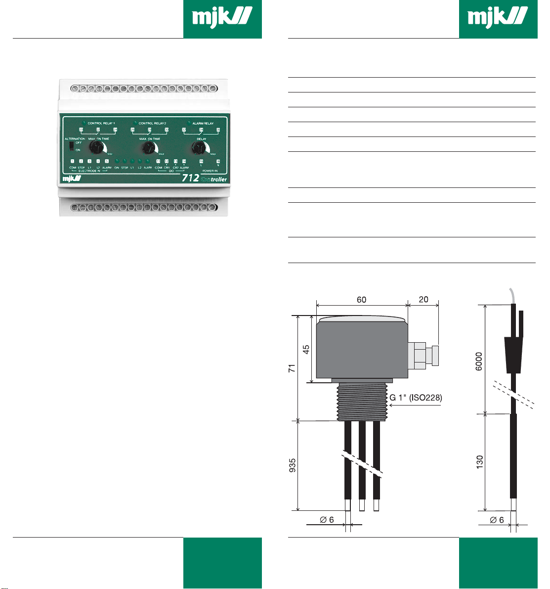
Specifications
ConTroller 712
Dimensions: 86 x 105 x 60 mm (h x w x d)
Power supply: 230 V AC +/- 10 %
Consumption: Approx. 5 VA
Temp. range: - 10 … + 60 °C
Inputs: 4 x level electrodes and 1 x ground electrode
Udgange: 3 x voltage free changeover relays.
(Max. load 4 A resistive / 250 V AC)
Status signas to MJK GSM/GPRS modem.
Enclosure: IP 22
Electrodes With cable For base Base
Dimension:
∅ 6 x ∅ 6 x ∅ 60 x
130 mm 935 mm 71 mm
Level measurement with electrodes
ConTroller 712 is measuring the level in the well by means of
base mounted or suspended level electrodes.
The mounting height of the electrodes determines the start and
stop levels for the pumps and the alarm level.
ConTroller 712 is equipped with 3 voltage free control relays, of
which 2 are used for control of 2 pumps/valve actuators, and
the remaining is alarm output.
Up to 5 level electrodes can be connected, of which 1
electrode is common/ground electrode.
MJK Automation A/S
M712GB0505
1
Byageren 7
DK-2850 Nærum
Denmark
mjk@mjk.com
www.mjk.com
M712GB0505
MJK Automation A/S
2
Byageren 7
DK-2850 Nærum
Denmark
Tel.: +45 45 56 06 56
Fax: +45 45 56 06 56
Page 2
CONTROLLER 712
CONTROLLER 712
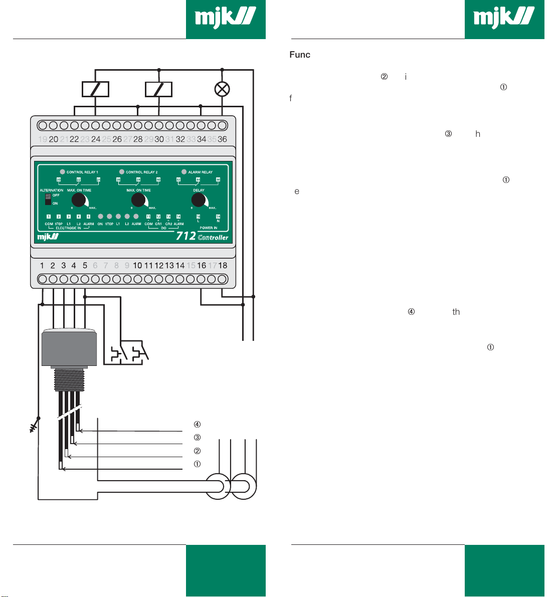
Electrical connection
K1 K2 Alarm
Ground connection in well
Auxiliary switches
on thermal
overload relay
Q1 Q2
activates the alarm
output on overload
trip.
Max. level alarm
Start level pump 2
Start level pump 1
Stop level
Function
Relay no. 1 is activated when the level in the well has reached
the first start electrode Á, which will start pump no. 1. The
pump will be stopped again when the stop electrode À goes
free of the level surface OR when the preset running time has
exeeded.
Relay no. 2 will be activated if the level continues to rise and the
level reaches the second start elektrode Â, which will start pump
no. 2. (Note: BOTH pumps will be started if pump no. 1 in the
meantime has been stopped because of runout of the preset
running time.)
The pump(s) will be stopped when the stop electrode À goes
free of the level surface.
Alarm output
The alarm output is equipped with a timer which is set by means
of the potmeter 'DELAY' on the front panel. This means that an
alarm condition will not activate the alarm relay before runout of
the preset delay time.
The following situations will activate the alarm:
1: When a pump has been in uninterrupted service during a
period beyond the preset maximum running time.
(The pump will also be stopped.)
2: When the alarm electrode Ãÿreaches the liquid surface.
(The pumps are kept running until the preset maximum
running time is reached.)
LN
The alarm is deactivated when the stop electrode À goes free of
the level surface.
Function with short-circuited electrodes
Electrode controls are sensitive to smudging and short-circuiting
of the electrodes, and a piece of wet paper will typically shortcircuit the stop electrode to the ground electrode.
Ã
Â
Á
À
ConTroller 712 will therefore run the pumps on the preset
running time if the electrodes are smudged or short-circuited.
Status outputs
ConTroller 712 is equipped with status outputs for transmission
of service and alarm status to MJK GSM/GPRS-COM for
communication to i.e. a SCADA system.
M712GB0505
Pump 1
Pump 2
MJK Automation A/S
3
Byageren 7
DK-2850 Nærum
Denmark
mjk@mjk.com
www.mjk.com
M712GB0505
4
MJK Automation A/S
Byageren 7
DK-2850 Nærum
Denmark
Tel.: +45 45 56 06 56
Fax: +45 45 56 06 56
Page 3

CONTROLLER 712
Settings
'Max. on time:'
2 potmeters for each relay output are placed in the front panel.
The setting of the potmeters determines the maximum
continuous activation time for the belonging relay:
Setting of the maximum
continuous running time for
the pump for each start.
(Approx. 0,1 to 8 min.)
'Delay:'
If the level for any reason should reach the alarm electrode, or if
one of the pumps has been stopped because of runout of the
preset maximum continuous running time, the caused alarm will
be delayed for a period set by means of this potmeter.
An alarm will also occur if the level does not reach the stop
electrode within a fixed running period.
CONTROLLER 712
'Alternation:'
Relay no. 1 will always be activated first, if the alternation switch
is set to 'OFF'. Thereafter, relay no. 2 is activated if the level
continues to rise
If the switch is set to 'ON', ConTroller 712 will alternate the two
relay outputs so that they will be leading every second time and
thus distribute the service hours equally between the two
pumps.
Maintenance
ConTroller 712 requires no particular maintenance.
The electrodes should be cleaned periodically.
M712GB0505
Setting of activation delay for
the alarm relay.
(Approx. 0,2 to 30 min.)
5
MJK Automation A/S
Byageren 7
DK-2850 Nærum
Denmark
mjk@mjk.com
www.mjk.com
M712GB0505
MJK Automation A/S
6
Byageren 7
DK-2850 Nærum
Denmark
Tel.: +45 45 56 06 56
Fax: +45 45 56 06 56
 Loading...