

Page 1
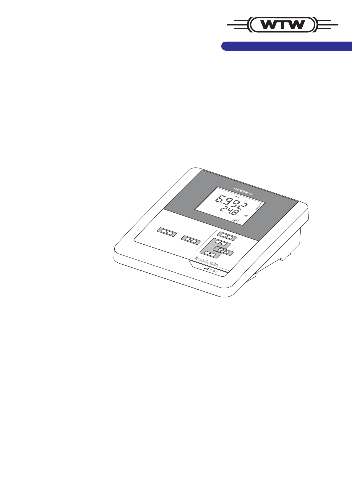
pH 7110
Operating manual
ba75925e02 12/2011
pH meter
Page 2

pH 7110
Copyright © Weilheim 2011, WTW GmbH
Reproduction in whole - or even in part - is prohibited without the express
written permission of WTW GmbH, Weilheim.
Printed in Germany.
2 ba75925e02 12/2011
Page 3

pH 7110 Contents
pH 7110 - Contents
1 Overview . . . . . . . . . . . . . . . . . . . . . . . . . . . . . . . . . 7
1.1 pH 7110 meter. . . . . . . . . . . . . . . . . . . . . . . . . . . . . . . . . . . . . . . . . . 7
1.2 Sensors . . . . . . . . . . . . . . . . . . . . . . . . . . . . . . . . . . . . . . . . . . . . . . . 7
2 Safety. . . . . . . . . . . . . . . . . . . . . . . . . . . . . . . . . . . . 8
2.1 Safety information . . . . . . . . . . . . . . . . . . . . . . . . . . . . . . . . . . . . . . . 8
2.1.1 Safety information in the operating manual. . . . . . . . . . . . . . . . 8
2.1.2 Safety signs on the meter . . . . . . . . . . . . . . . . . . . . . . . . . . . . . 8
2.1.3 Further documents providing safety information. . . . . . . . . . . . 8
2.2 Safe operation . . . . . . . . . . . . . . . . . . . . . . . . . . . . . . . . . . . . . . . . . . 9
2.2.1 Authorized use . . . . . . . . . . . . . . . . . . . . . . . . . . . . . . . . . . . . . 9
2.2.2 Requirements for safe operation. . . . . . . . . . . . . . . . . . . . . . . . 9
2.2.3 Unauthorized use . . . . . . . . . . . . . . . . . . . . . . . . . . . . . . . . . . . 9
3 Commissioning. . . . . . . . . . . . . . . . . . . . . . . . . . . 10
3.1 Scope of delivery . . . . . . . . . . . . . . . . . . . . . . . . . . . . . . . . . . . . . . . 10
3.2 Power supply. . . . . . . . . . . . . . . . . . . . . . . . . . . . . . . . . . . . . . . . . . 10
3.3 Initial commissioning . . . . . . . . . . . . . . . . . . . . . . . . . . . . . . . . . . . . 10
3.3.1 Inserting the batteries . . . . . . . . . . . . . . . . . . . . . . . . . . . . . . . 10
3.3.2 Connecting the power pack. . . . . . . . . . . . . . . . . . . . . . . . . . . 11
3.3.3 Mounting the stand . . . . . . . . . . . . . . . . . . . . . . . . . . . . . . . . . 12
4 Operation. . . . . . . . . . . . . . . . . . . . . . . . . . . . . . . . 13
4.1 General operating principles . . . . . . . . . . . . . . . . . . . . . . . . . . . . . . 13
4.1.1 Keypad . . . . . . . . . . . . . . . . . . . . . . . . . . . . . . . . . . . . . . . . . . 13
4.1.2 Display . . . . . . . . . . . . . . . . . . . . . . . . . . . . . . . . . . . . . . . . . . 14
ba75925e02 12/2011 3
Page 4

Contents pH 7110
4.1.3 Status information . . . . . . . . . . . . . . . . . . . . . . . . . . . . . . . . . 14
4.1.4 Socket field . . . . . . . . . . . . . . . . . . . . . . . . . . . . . . . . . . . . . . 15
4.2 Switching on the meter. . . . . . . . . . . . . . . . . . . . . . . . . . . . . . . . . . 15
4.3 Switching off the meter. . . . . . . . . . . . . . . . . . . . . . . . . . . . . . . . . . 15
4.4 Navigation . . . . . . . . . . . . . . . . . . . . . . . . . . . . . . . . . . . . . . . . . . . 16
4.4.1 Operating modes . . . . . . . . . . . . . . . . . . . . . . . . . . . . . . . . . . 16
4.4.2 Measuring mode (measured value display) . . . . . . . . . . . . . . 16
4.4.3 Setting mode . . . . . . . . . . . . . . . . . . . . . . . . . . . . . . . . . . . . . 16
5 pH value . . . . . . . . . . . . . . . . . . . . . . . . . . . . . . . . . 18
5.1 Measuring. . . . . . . . . . . . . . . . . . . . . . . . . . . . . . . . . . . . . . . . . . . . 18
5.1.1 Measuring the pH value . . . . . . . . . . . . . . . . . . . . . . . . . . . . . 18
5.1.2 Measuring the temperature . . . . . . . . . . . . . . . . . . . . . . . . . . 19
5.2 Calibration . . . . . . . . . . . . . . . . . . . . . . . . . . . . . . . . . . . . . . . . . . . 19
5.2.1 Why calibrate? . . . . . . . . . . . . . . . . . . . . . . . . . . . . . . . . . . . . 19
5.2.2 When to calibrate? . . . . . . . . . . . . . . . . . . . . . . . . . . . . . . . . . 20
5.2.3 Automatic calibration (AutoCal) . . . . . . . . . . . . . . . . . . . . . . . 20
5.2.4 Manual calibration (ConCal) . . . . . . . . . . . . . . . . . . . . . . . . . 22
5.2.5 Calibration points . . . . . . . . . . . . . . . . . . . . . . . . . . . . . . . . . . 24
5.2.6 Calibration data . . . . . . . . . . . . . . . . . . . . . . . . . . . . . . . . . . . 24
6 ORP . . . . . . . . . . . . . . . . . . . . . . . . . . . . . . . . . . . . 27
6.1 Measuring. . . . . . . . . . . . . . . . . . . . . . . . . . . . . . . . . . . . . . . . . . . . 27
6.1.1 Measuring the ORP . . . . . . . . . . . . . . . . . . . . . . . . . . . . . . . . 27
6.1.2 Measuring the temperature . . . . . . . . . . . . . . . . . . . . . . . . . . 27
6.2 Calibration . . . . . . . . . . . . . . . . . . . . . . . . . . . . . . . . . . . . . . . . . . . 28
7 Settings . . . . . . . . . . . . . . . . . . . . . . . . . . . . . . . . . 29
7.1 Measurement settings (pH) . . . . . . . . . . . . . . . . . . . . . . . . . . . . . . 29
7.1.1 Changing the settings for pH measurements. . . . . . . . . . . . . 29
7.1.2 Buffer sets for calibration . . . . . . . . . . . . . . . . . . . . . . . . . . . . 30
7.1.3 Calibration interval . . . . . . . . . . . . . . . . . . . . . . . . . . . . . . . . . 31
7.2 Measurement settings (ORP). . . . . . . . . . . . . . . . . . . . . . . . . . . . . 31
7.2.1 Changing the settings for ORP measurements . . . . . . . . . . . 31
4 ba75925e02 12/2011
Page 5

pH 7110 Contents
7.3 Sensor-independent settings . . . . . . . . . . . . . . . . . . . . . . . . . . . . . 32
7.3.1 Changing the sensor-independent settings . . . . . . . . . . . . . . 32
7.3.2 Energy saving (battery operation) . . . . . . . . . . . . . . . . . . . . . 32
8 Reset . . . . . . . . . . . . . . . . . . . . . . . . . . . . . . . . . . . 34
8.1 Resetting the calibration values . . . . . . . . . . . . . . . . . . . . . . . . . . . 34
8.2 Resetting the measurement and system settings . . . . . . . . . . . . . 34
9 Maintenance, cleaning, disposal. . . . . . . . . . . . . 36
9.1 Maintenance. . . . . . . . . . . . . . . . . . . . . . . . . . . . . . . . . . . . . . . . . . 36
9.1.1 General maintenance activities . . . . . . . . . . . . . . . . . . . . . . . 36
9.1.2 Replacing the batteries . . . . . . . . . . . . . . . . . . . . . . . . . . . . . 36
9.2 Cleaning . . . . . . . . . . . . . . . . . . . . . . . . . . . . . . . . . . . . . . . . . . . . . 37
9.3 Packing. . . . . . . . . . . . . . . . . . . . . . . . . . . . . . . . . . . . . . . . . . . . . . 37
9.4 Disposal . . . . . . . . . . . . . . . . . . . . . . . . . . . . . . . . . . . . . . . . . . . . . 37
10 What to do if... . . . . . . . . . . . . . . . . . . . . . . . . . . . . 38
10.1 pH. . . . . . . . . . . . . . . . . . . . . . . . . . . . . . . . . . . . . . . . . . . . . . . . . . 38
10.1.1 No stable measured value . . . . . . . . . . . . . . . . . . . . . . . . . . . 38
10.1.2 Error message CalError . . . . . . . . . . . . . . . . . . . . . . . . . . . . . 38
10.1.3 Error message OFL, UFL. . . . . . . . . . . . . . . . . . . . . . . . . . . . 39
10.2 ORP . . . . . . . . . . . . . . . . . . . . . . . . . . . . . . . . . . . . . . . . . . . . . . . . 39
10.2.1 No stable measured value . . . . . . . . . . . . . . . . . . . . . . . . . . . 39
10.2.2 Error message OFL, UFL. . . . . . . . . . . . . . . . . . . . . . . . . . . . 40
10.3 General information . . . . . . . . . . . . . . . . . . . . . . . . . . . . . . . . . . . . 40
10.3.1 Symbol for calibration evaluation flashes. . . . . . . . . . . . . . . . 40
10.3.2 [LoBat] display . . . . . . . . . . . . . . . . . . . . . . . . . . . . . . . . . . . . 40
10.3.3 Instrument does not react to keystroke . . . . . . . . . . . . . . . . . 41
10.3.4 Displaying the software version (meter). . . . . . . . . . . . . . . . . 41
11 Technical data . . . . . . . . . . . . . . . . . . . . . . . . . . . . 42
11.1 Measuring ranges, resolution, accuracy. . . . . . . . . . . . . . . . . . . . . 42
11.1.1 Measuring ranges, resolution. . . . . . . . . . . . . . . . . . . . . . . . . 42
11.1.2 Manual temperature input . . . . . . . . . . . . . . . . . . . . . . . . . . . 42
ba75925e02 12/2011 5
Page 6

Contents pH 7110
11.1.3 Accuracy (± 1 digit) . . . . . . . . . . . . . . . . . . . . . . . . . . . . . . . . 43
11.2 General data. . . . . . . . . . . . . . . . . . . . . . . . . . . . . . . . . . . . . . . . . . 43
12 Glossary. . . . . . . . . . . . . . . . . . . . . . . . . . . . . . . . . 46
12.1 pH/ORP . . . . . . . . . . . . . . . . . . . . . . . . . . . . . . . . . . . . . . . . . . . . . 46
12.2 General information . . . . . . . . . . . . . . . . . . . . . . . . . . . . . . . . . . . . 47
13 Index. . . . . . . . . . . . . . . . . . . . . . . . . . . . . . . . . . . . 49
6 ba75925e02 12/2011
Page 7
pH 7110 Overview
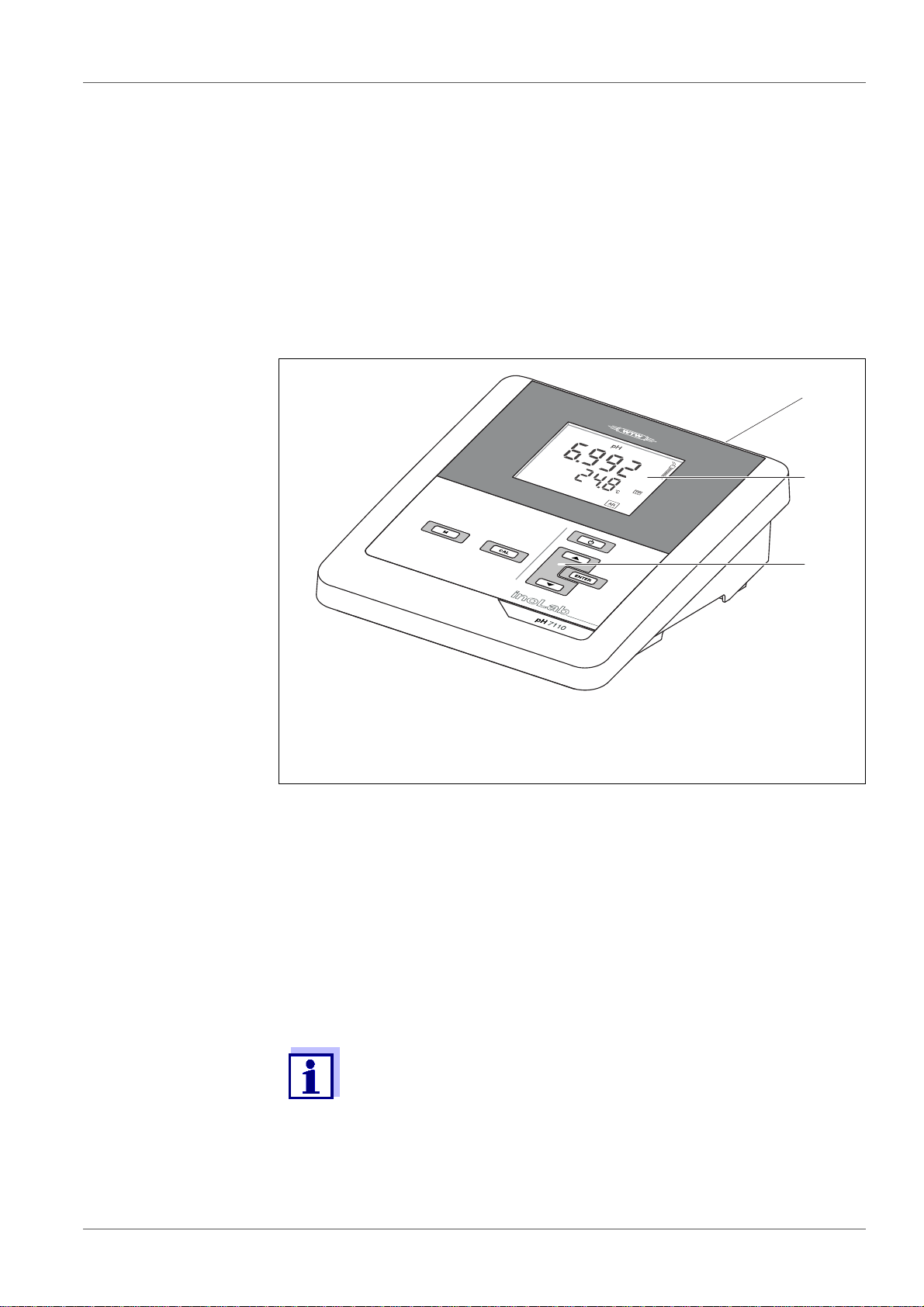
1
2
3
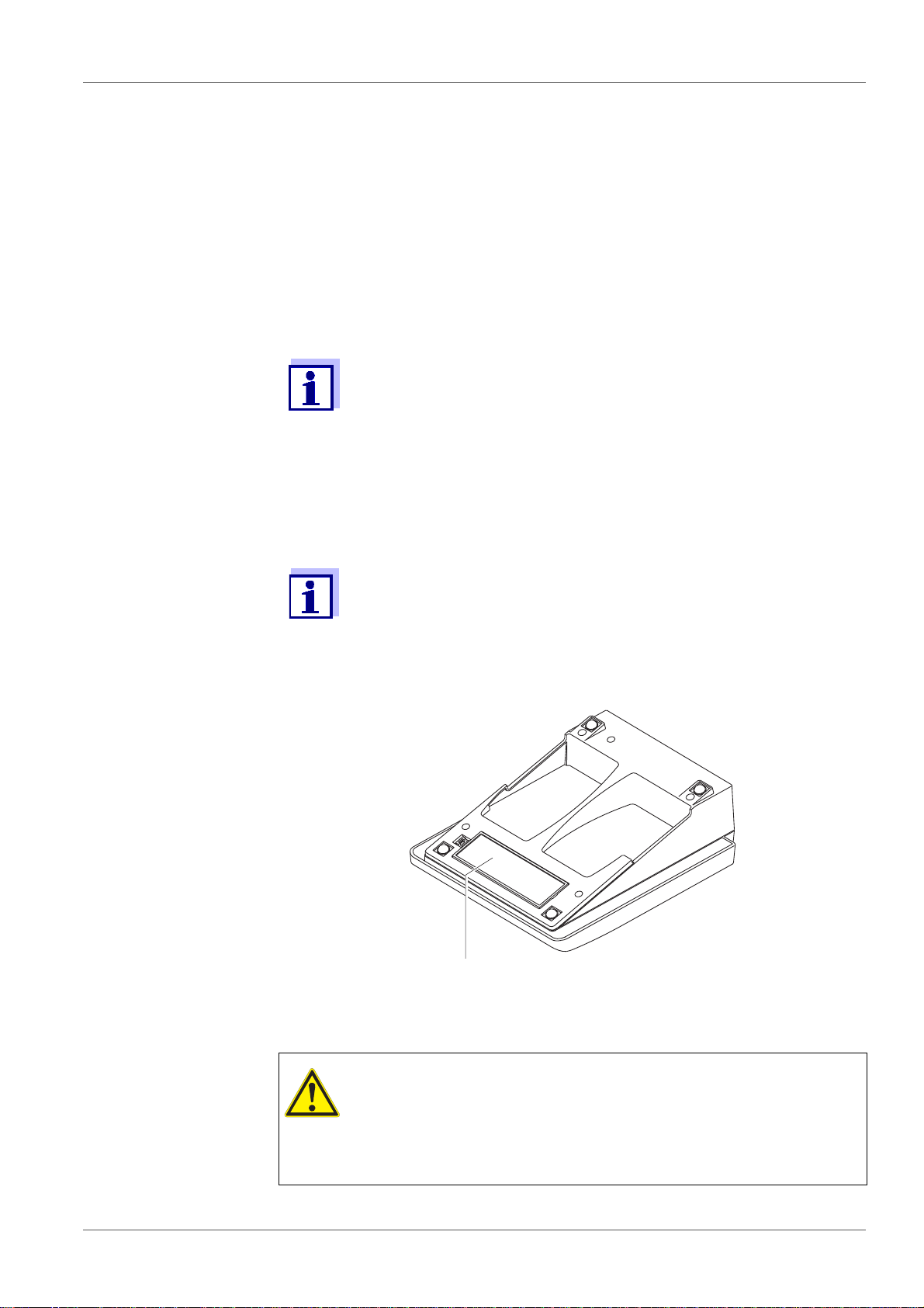
1Overview
1.1 pH 7110 meter
The pH 7110 compact digital precision meter enables you to perform pH and
ORP measurements quickly and reliably.
The pH 7110 provides the maximum degree of operating comfort, reliability and
measuring certainty for all applications.
1 Keypad
2Display
3 Socket field
1.2 Sensors
A measuring system ready to measure consists of the pH 7110 meter and a
suitable sensor.
The pH 7110 can be operated with the following sensors:
• pH electrode
• ORP electrode
Information on available sensors is given on the Internet and in the
WTW catalog, "Laboratory and field instrumentation".
ba75925e02 12/2011 7
Page 8
Safety pH 7110
2 Safety
2.1 Safety information
2.1.1 Safety information in the operating manual
This operating manual provides important information on the safe operation of
the meter. Read this operating manual thoroughly and make yourself familiar
with the meter before putting it into operation or working with it. The operating
manual must be kept in the vicinity of the meter so you can always find the information you need.
Important safety instructions are highlighted in this operating manual. They are
indicated by the warning symbol (triangle) in the left column. The signal word
(e.g. "CAUTION") indicates the level of danger:
WARNING
indicates a possibly dangerous situation that can lead to
serious (irreversible) i njury or death if the safety inst ruction is
not followed.
CAUTION
indicates a possibly dangerous situation that can lead to
slight (reversible) injury if the safety instruction is not
followed.
NOTE
indicates a possibly dangero us situation where goods might be damaged
if the actions mentioned are not taken.
2.1.2 Safety signs on the meter
Note all labels, information signs and safety symbols on the meter and in the
battery compartment. A warning symbol (triangle) without text refers to safety
information in this operating manual.
2.1.3 Further documents providing safety information
The following documents provide additional information, which you should
observe for your safety when working with the measuring system:
• Operating manuals of sensors and other accessories
• Safety datasheets of calibration or maintenance accessories (such as buffer
solutions, electrolyte solutions, etc.)
8 ba75925e02 12/2011
Page 9

pH 7110 Safety
2.2 Safe operation
2.2.1 Authorized use
This meter is authorized exclusively for pH and ORP measurements in the
laboratory.
Only the operation and running of the meter according to the instructions and
technical specifications given in this operating manual is authorized (see
section 11 T
Any other use is considered unauthorized.
2.2.2 Requirements for safe operation
Note the following points for safe operation:
• The meter may only be operated according to the authorized use specified
above.
• The meter may only be supplied with power by the energy sources
mentioned in this operating manual.
• The meter may only be operated under the environmental conditions
mentioned in this operating manual.
• The meter may only be opened if this is explicitly described in this operating
manual (example: Inserting the batteries).
ECHNICAL DATA, page 42).
2.2.3 Unauthorized use
The meter must not be put into operation if:
• it is visibly damaged (e.g. after being transported)
• it was stored under adverse conditions for a lengthy period of time (storing
conditions, see section 11 T
ECHNICAL DATA, page 42).
ba75925e02 12/2011 9
Page 10

Commissioning pH 7110
3 Commissioning
3.1 Scope of delivery
• pH 7110 meter
• 4 batteries 1.5 V Mignon type AA
• Power pack
• Stand
• Stand holder
• Short instructions
• Detailed operating manual (4 languages)
• CD-ROM with detailed operating manual
3.2 Power supply
The pH 7110 is supplied with power in the following ways:
• Mains operation with the supplied power pack.
• Battery operation (4 x alkaline manganese batteries, type AA)
3.3 Initial commissioning
Perform the following activities:
• Insert the supplied batteries
• Connect the power pack (mains operation)
• Mount the stand
• Switch on the meter
(see section 4.2 S
3.3.1 Inserting the batteries
You can operate the meter either with normal batteries or with
rechargeable batteries (Ni-MH).
In order to charge the batteries, an external charging device is
required.
WITCHING ON THE METER, page 15)
10 ba75925e02 12/2011
Page 11
pH 7110 Commissioning
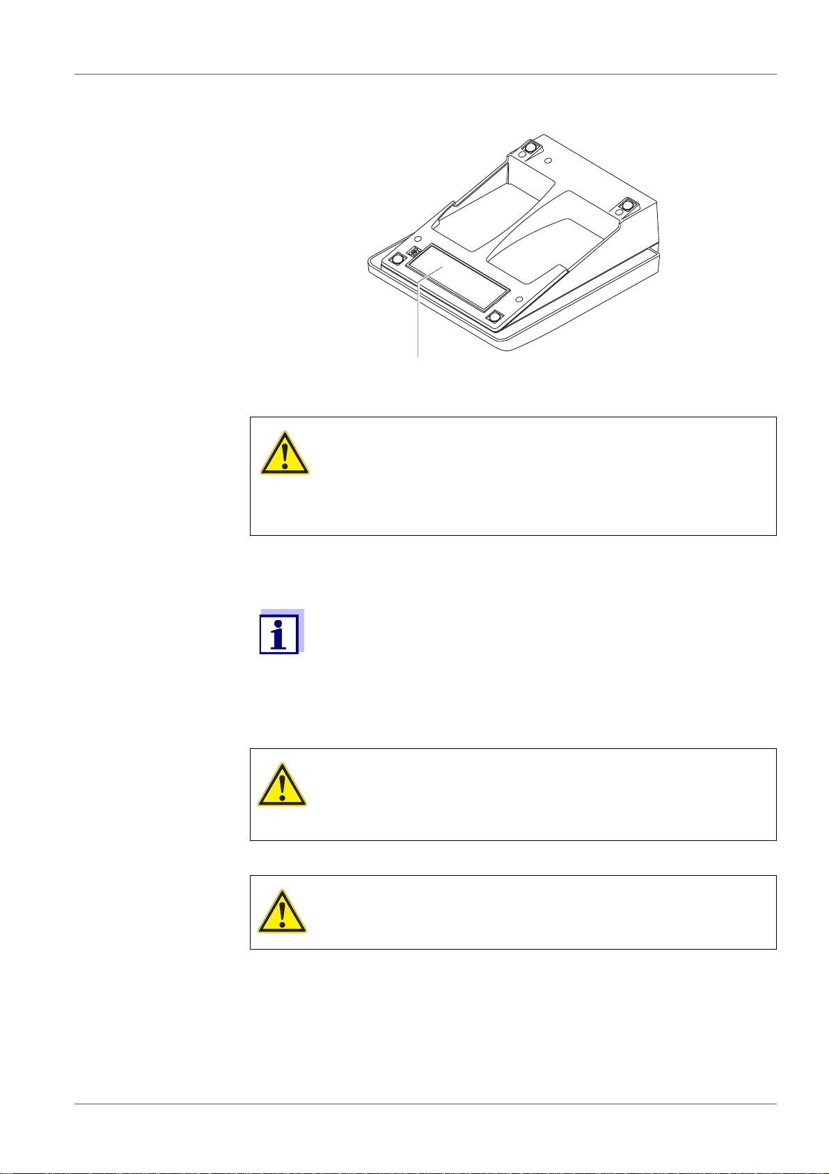
2
1. Open the battery compartment (2) on the underside of the meter.
2. Insert four batteries in the battery compartment.
CAUTION
Make sure that the poles of the batteries are positioned
correctly.
The ± signs on the batteries must correspond to the ± signs
in the battery compartment.
3. Close the battery compartment tightly.
When the batteries are nearly empty, the [LoBat] status indicator is
displayed.
3.3.2 Connecting the power pack
CAUTION
The line voltage at the operating site must lie withi n the input
voltage range of the or iginal po wer pack (see section 11 T
NICAL DATA, page 42).
ECH-
CAUTION
Use original power packs only (see section 11 T
ECHNICAL DATA,
page 42).
1. Connect the plug of the power pack to the socket for the power pack on
the pH 7110.
2. Connect the original power pack to an easily accessible power outlet.
ba75925e02 12/2011 11
Page 12
Commissioning pH 7110
1
2
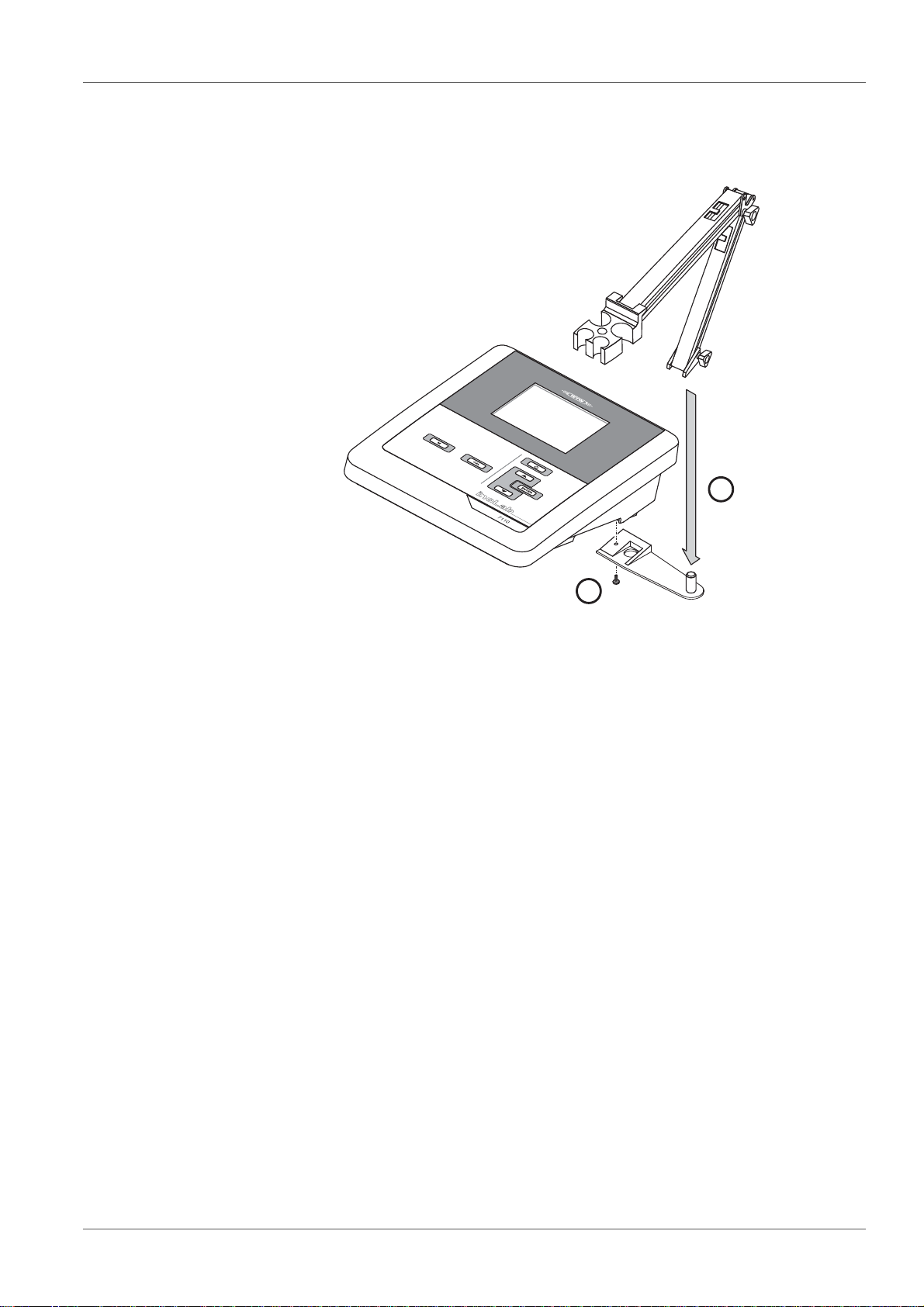
3.3.3 Mounting the stand
The stand base can be mounted at the right side of the meter.
12 ba75925e02 12/2011
Page 13
pH 7110 Operation
4Operation
4.1 General operating principles
This section contains basic information on the operation of the pH 7110.
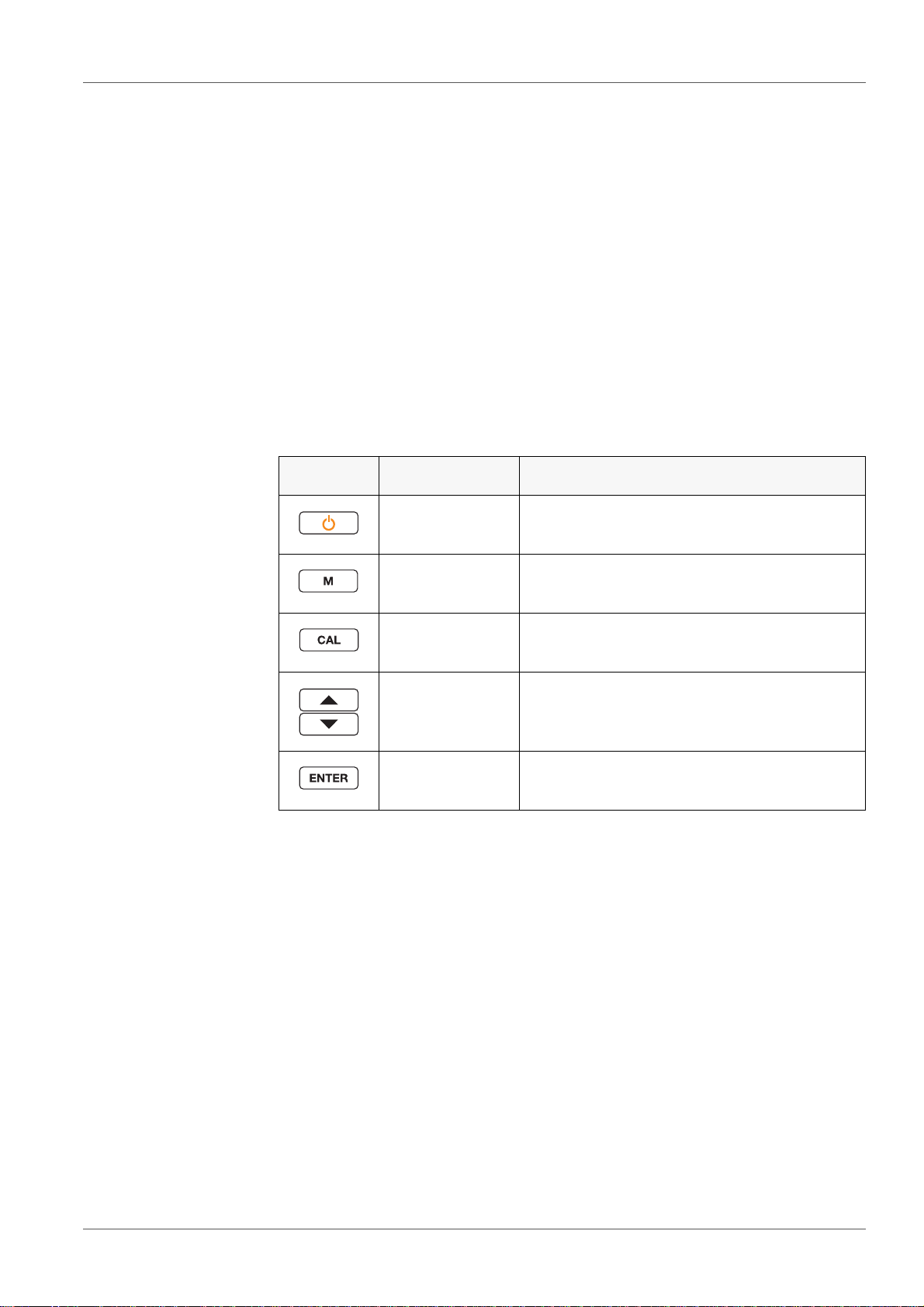
4.1.1 Keypad
In this operating manual, keys are indicated by brackets <..> .
The key symbol (e.g. <ENTER>) generally indicates a short keystroke (under
2 sec) in this operating manual. A long keystroke (approx. 2 sec) is indicated
by the underscore behind the key symbol (e.g. <ENTER__>).
Key Symbol Meaning
<On/Off>
<On/Off__>
<M>
<M__>
<CAL>
<CAL__>
<><>
<__><__>
<ENTER>
<ENTER__>
Switches the meter on or off
Resets calibration data
Selects the measured parameter
Opens the measurement settings
Calls up the calibration procedure
Displays the calibration data
Increments, decrements values
Increments, decrements values continuously
Confirms entries
Opens the menu for system settings
ba75925e02 12/2011 13
Page 14
Operation pH 7110
8
88
8
8
1
8
8
8
°
C
°F
UpH
mV/pH
LoBat
AutoCal DIN
AutoCal TEC ConCal AR
TP
CalError
%
Time
3
2
4
5
1
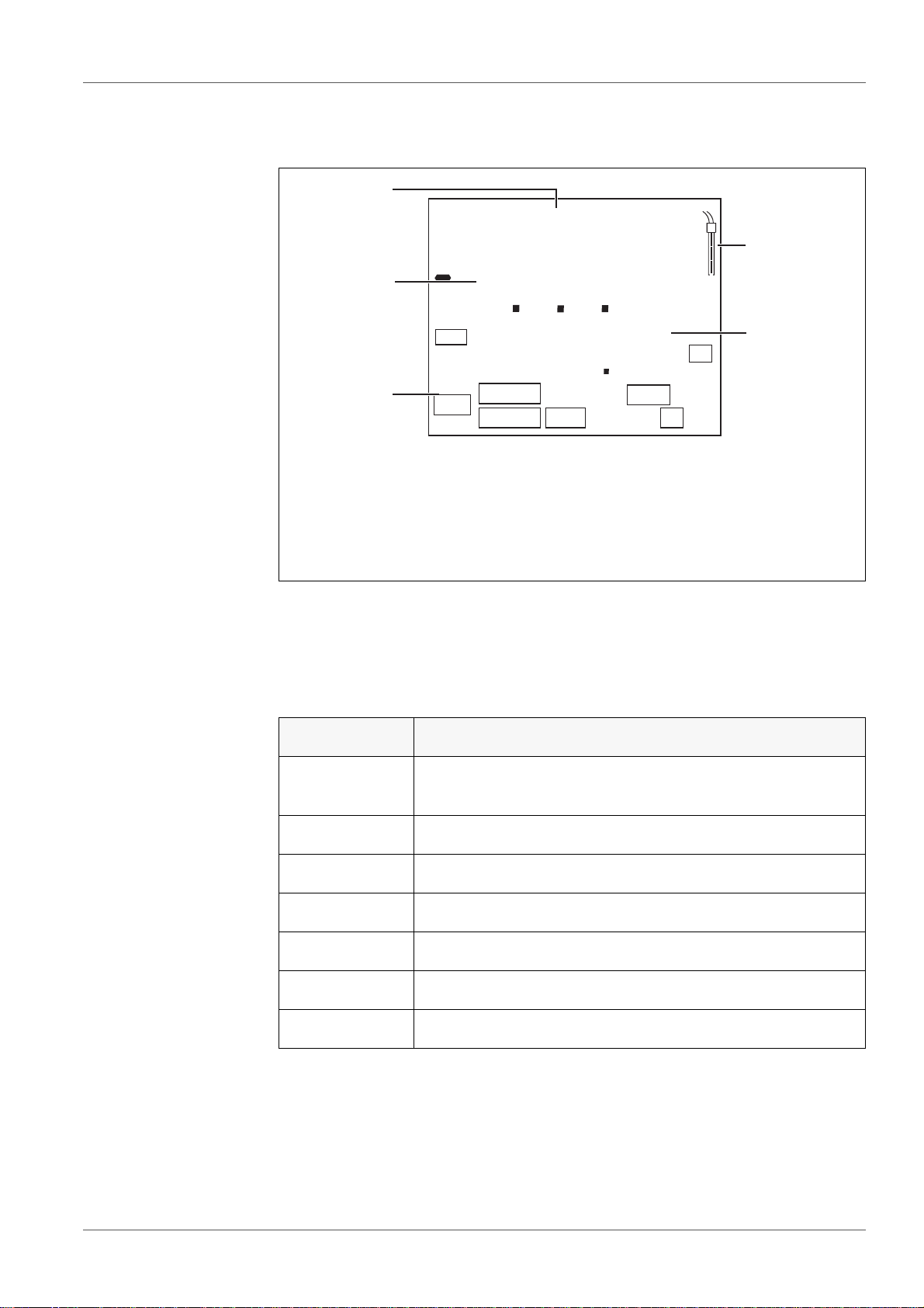
4.1.2 Display
1 Status information
2 Measured value (with unit)
3 Measured parameter
4 Sensor symbol (calibration evaluation, calibration interval)
5 Measured temperature (with unit)
4.1.3 Status information
Display Meaning
[AutoCal TEC]
[AutoCal DIN]
[ConCal] Calibration with any buffers
[CalError] An error occurred during calibration
[AR] Stability control (AutoRead) is active
[TP] Temperature measurement active
Calibration with automatic buffer recognition, e.g. with the
buffer set: Technical buffers
[Time] Setting of calibration interval
[LoBat] Batteries are almost empty
14 ba75925e02 12/2011
Page 15
pH 7110 Operation
1
2
3
4
5
8
4
2
2
9
9
6
pH
°
C
TP
AR
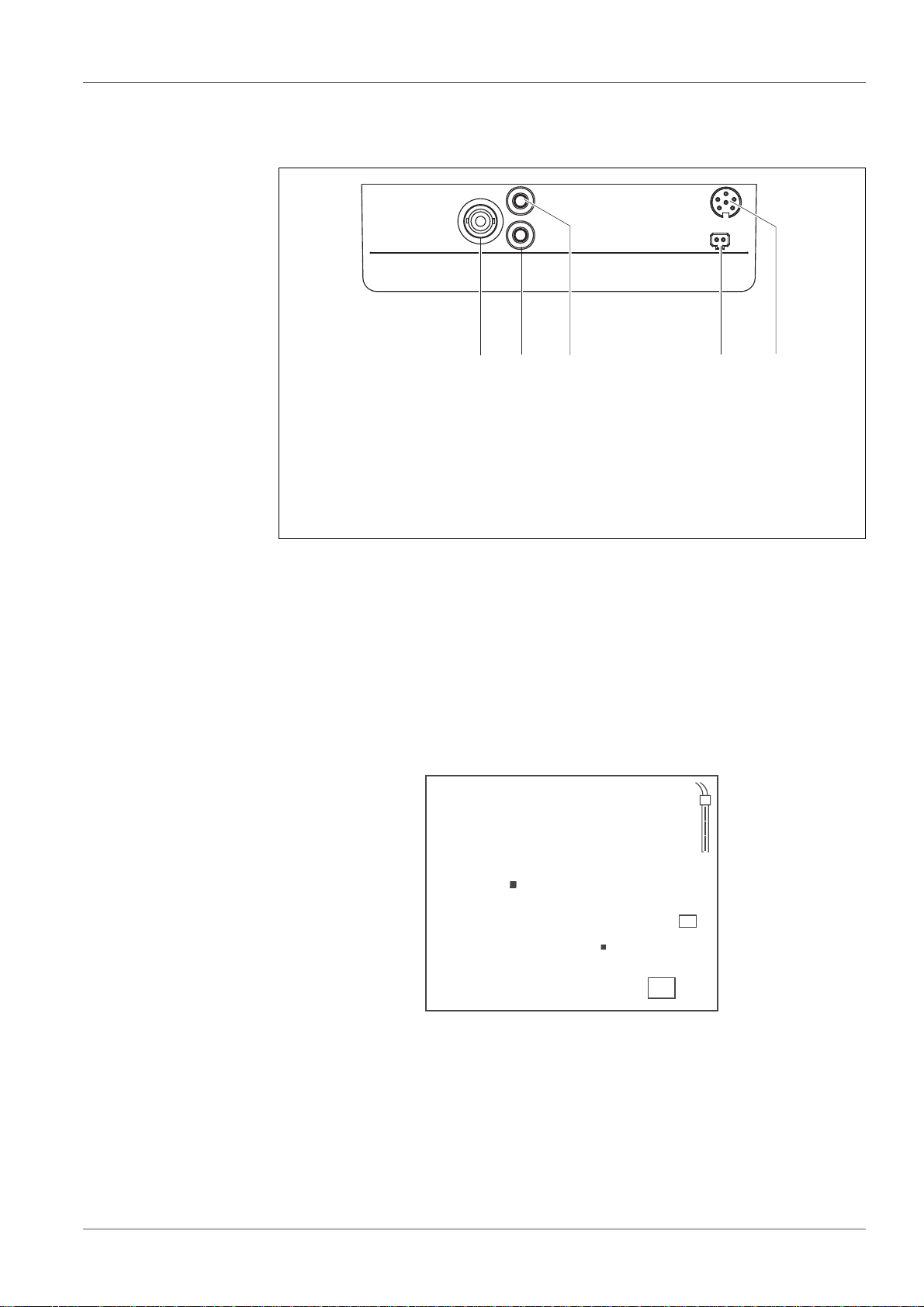
4.1.4 Socket field
1 pH electrode
2 Reference electrode
3 Temperature sensor
4 Power pack
5 Service interface
4.2 Switching on the meter
1. Switch on the meter with <On/Off>.
The meter performs a self-test.
The meter switches to the measuring mode (measured value display).
2. Connect the sensor.
The meter is ready to measure.
4.3 Switching off the meter
1. Switch off the meter with <On/Off>.
The meter is switched off.
ba75925e02 12/2011 15
Page 16
Operation pH 7110
When the meter is powered by the batteries, it switches itself off
automatically after an adjustable interval to save the batteries (see
section Automatic switch-off function, page 32).
4.4 Navigation
4.4.1 Operating modes
The meter has the following operating modes:
Operating mode Description
Measuring The measurement data of the connected sensor are
shown in the measured value display
Calibration The course of a calibration with calibration informa-
tion, functions and settings is displayed
Transmitting data The meter transmits measuring data and calibration
records to a USB-B interface automatically or manually.
Setting A setting is displayed.
4.4.2 Measuring mode (measured value display)
The following functions are available in the measuring mode (measured value
display):
• Change the display in the selected measuring window (e. g. pH <-> mV) by
pressing <M>
• To open the measurement settings, press <M__> (long pressure).
• To open the system settings, press <ENTER__> (long pressure).
4.4.3 Setting mode
The following functions are available in the setting mode:
• To change the current setting, press <><>.
• Confirm the setting with <ENTER>.
The next setting is displayed.
The settings are stored.
16 ba75925e02 12/2011
Page 17

pH 7110 Operation
When the last setting is confirmed, the setting menu is automatically quit.
• Press <M> to exit the setting mode.
ba75925e02 12/2011 17
Page 18

pH value pH 7110
8
4
2
2
9
9
6
pH
°
C
TP
AR
5pH value
5.1 Measuring
5.1.1 Measuring the pH value
To ensure the high measurement accuracy of the measuring system, always measure with A current calibration (see section 5.2
C
ALIBRATION, page 19).
1. Connect the pH electrode to the meter.
2. When measuring without temperature sensor: Temper the test sample or
measure the current temperature.
3. If necessary, select the measured parameter (pH) with <M>.
4. Immerse the pH electrode in the test sample.
The measured value is checked for stability (stability control).
The [AR] status display flashes.
5. When measuring without temperature sensor: Enter the temperature of
the buffer with <><>.
6. Wait for a stable measured value.
The [AR] display indicator no longer flashes.
Stability control (AutoRead )
During the measuring procedure, the stability control function is automatically
activated.
The stability control function (AutoRead) continually checks the stability of the
18 ba75925e02 12/2011
measured values in the monitored time interval. The stability has a consider-
able impact on the reproducibility of measured values. The [AR] display indi-
cator flashes until a stable value is measured.
Page 19

pH 7110 pH value
Stability criteria (AutoRead )
Measured parameter Time interval Stability in the time interval
pH value 15 seconds Δ pH: Better than 0.02
Temperature 15 seconds Δ T (° C): Better than 0.3
The minimum duration until a measured value is assessed as stable is the
monitored time interval. The actual duration is mostly longer.
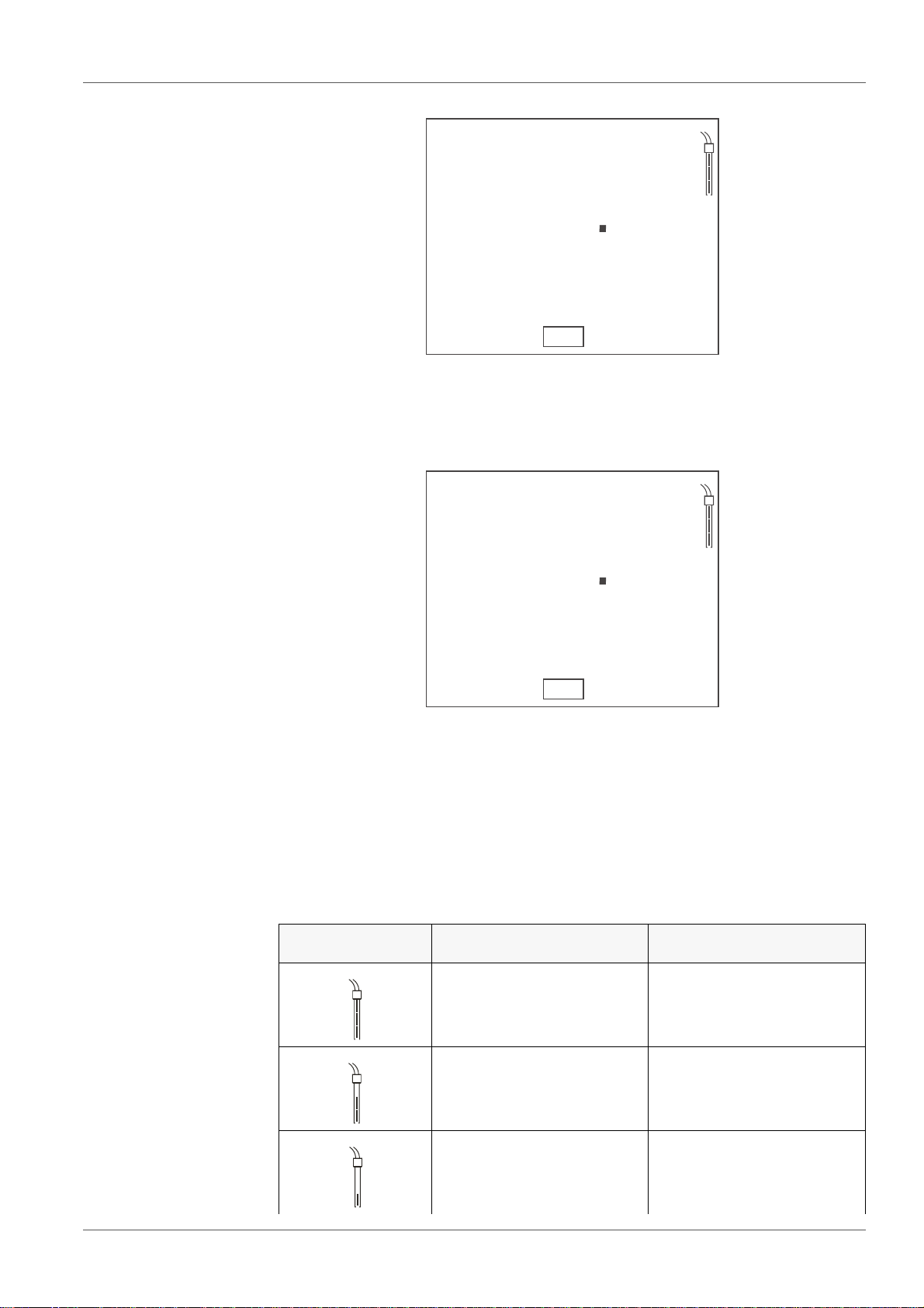
5.1.2 Measuring the temperature
For reproducible pH measurements, it is essential to measure the temperature
of the test sample.
You have the following options to measure the temperature:
• Automatic measurement of the temperature with the temperature sensor
(NTC30 or Pt1000) integrated in the sensor.
• Measurement with an external temperature sensor.
• Manual determination and input of the temperature.
The measuring instrument recognizes whether a suitable sensor is connected
and automatically switches on the temperature measurement.
Which type of temperature measurement is active is indicated by the tempera-
ture display and the [TP] status indicator:
Resolution
Temperature
sensor
yes 0.1 °C [TP] Automatic with temperature
- 1 °C - Manual
If you wish to measure (or calibrate) without temperature sensor, proceed as
follows:
of the temp.
display
Status
indicator
Temp. measurement
sensor
1. Measure the current temperature of the test sample.
2. Set the temperature value with <><>.
5.2 Calibration
5.2.1 Why calibrate?
When a pH electrode is operated, its zero point (asymmetry) and slope change
with the course of time. As a result, an inexact measured value is displayed.
ba75925e02 12/2011 19
Page 20

pH value pH 7110
8
4
2
1
T
C
°
C
pH
AutoCal TEC
TP
Calibration determines and stores the current values of the zero point and
slope. Thus, you should calibrate at regular intervals.
5.2.2 When to calibrate?
• When the calibration interval has expired
• Routinely within the framework of the company quality assurance
• After connecting another combination electrode
5.2.3 Automatic calibration (AutoCal)
Use any one to three buffer solutions of a buffer set (technical buffers or DIN
buffers) in ascending or descending order.
Below, calibration with Technical buffers (TEC) is described. When other buffer
sets are used, other nominal buffer values are displayed. Apart from that, the
procedure is identical.
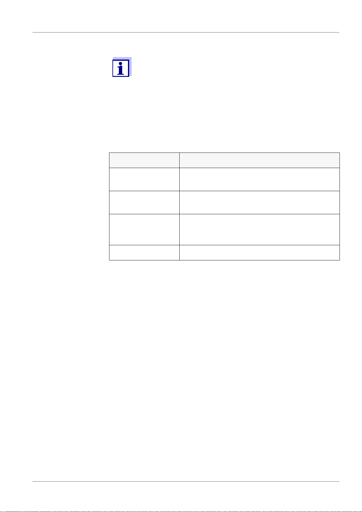
1. Start the calibration with <CAL>.
The calibration display for the first buffer appears.
2. When measuring without temperature sensor: Temper the buffer or
measure the current temperature.
3. If necessary, press <CAL> to select the buffer set used ([AutoCal TEC],
[AutoCal DIN]).
Ct1 or Cd1 is displayed.
4. Thoroughly rinse the pH electrode with deionized water.
5. Immerse the pH electrode in the first buffer solution.
6. When measuring without temperature sensor: Enter the temperature of
the buffer with <><>.
7. Start the measurement with <ENTER> .
The measured value is checked for stability (stability control).
The [AR] status display flashes.
20 ba75925e02 12/2011
The electrode voltage (mV) or the nominal value of the buffer is displayed
(setting: see section 7.1.1 C
MENTS, page 29).
HANGING THE SETTINGS FOR PH MEASURE-
Page 21
pH 7110 pH value
8
4
2
2
T
C
°
C
pH
AutoCal TEC
TP
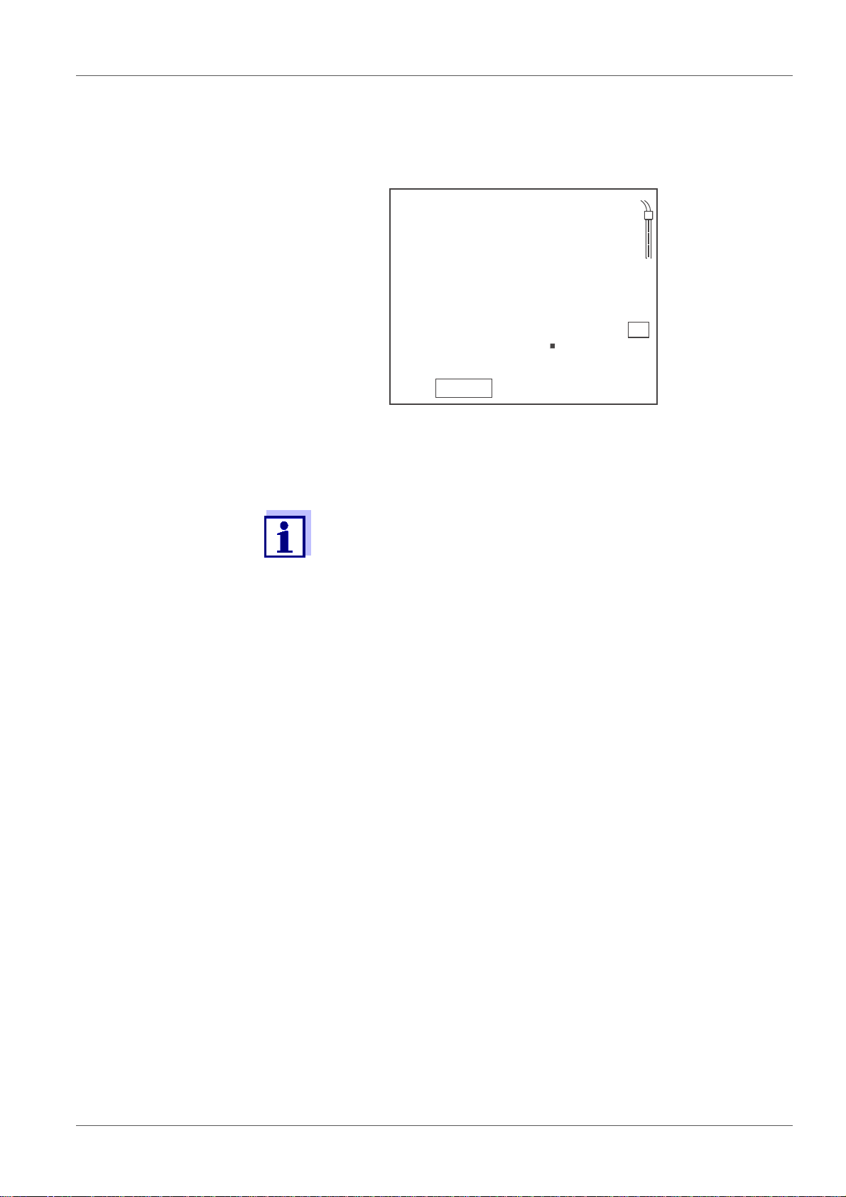
8. Wait for the measurement with stability control to be completed or termi-
nate the stability control with <ENTER>.
The calibration display for the next buffer appears.
Ct2 or Cd2 is displayed.
9. If necessary, finish the calibration procedure as a single-point calibration
with <M>.
The calibration record is displayed.
For single-point calibration, the instrument uses the Nernst
slope (-59.2 mV/pH at 25 °C) and determines the zero point
of the pH electrode.
or
Continue calibration using the next buffer with <ENTER>.
Continuing with two-point calibration
10. Thoroughly rinse the pH electrode with deionized water.
11. Immerse the pH electrode in the second buffer solution.
12. When measuring without temperature sensor: Enter the temperature of
the buffer with <><>.
13. Start the measurement with <ENTER> .
The measured value is checked for stability (stability control).
The [AR] status display flashes.
The electrode voltage (mV) or the nominal value of the buffer is displayed
(setting: see section 7.1.1 C
MENTS, page 29).
14. Wait for the measurement with stability control to be completed or termi-
nate the stability control and take over the calibration value with
<ENTER>.
The calibration display for the next buffer appears.
Ct3 or Cd3 is displayed.
HANGING THE SETTINGS FOR PH MEASURE-
ba75925e02 12/2011 21
Page 22

pH value pH 7110
8
4
2
3
T
C
°
C
pH
AutoCal TEC
TP
15. If necessary, finish the calibration procedure as a two-point calibration
with <M>.
The calibration record is displayed.
or
Continue calibration using the next buffer with <ENTER>.
Continuing with three-point calibrat ion
16. Thoroughly rinse the pH electrode with deionized water.
17. Immerse the pH electrode in the third buffer solution.
18. When measuring without temperature sensor: Enter the temperature of
the buffer with <><>.
19. Start the measurement with <ENTER> .
The measured value is checked for stability (stability control).
The [AR] status display flashes.
The electrode voltage (mV) or the nominal value of the buffer (setting: see
section 7.1.1 C
20. Wait for the measurement with stability control to be completed or termi-
nate the stability control and take over the calibration value with
<ENTER>.
The calibration record is displayed.
5.2.4 Manual calibration (ConCal)
Use any buffer solution for the single-point calibration. The calibration will be
the more accurate the nearer the pH value of the buffer solution is to that of the
test sample.
HANGING THE SETTINGS FOR PH MEASUREMENTS, page 29).
Use the following buffer solutions for two-point calibration:
• one buffer solution with pH 7.0 ± 0.5
• any other buffer solution
22 ba75925e02 12/2011
1. Start the calibration with <CAL>.
The calibration display for the first buffer appears.
2. When measuring without temperature sensor: Temper the buffer or
measure the current temperature.
Page 23
pH 7110 pH value
8
4
2
Y
S
A
°
C
TP
ConCal
8
4
2
O
L
s
°
C
TP
ConCal
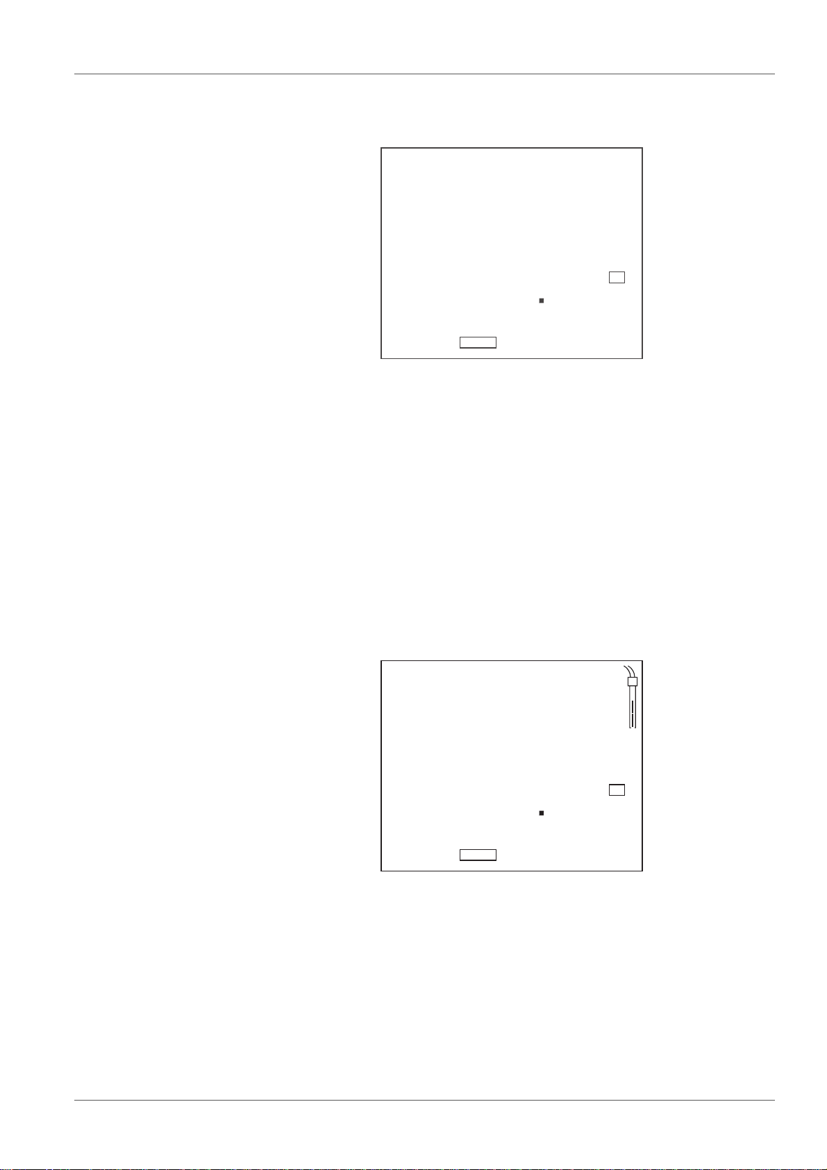
3. If necessary, press <CAL> to select the buffer set ([ConCal]).
ASY is displayed.
4. Thoroughly rinse the pH electrode with deionized water.
5. Immerse the pH electrode in the first buffer solution (pH 7.0 ± 0.5 for
two-point calibration).
6. When measuring without temperature sensor: Enter the temperature of
the buffer with <><>.
7. Start the measurement with <ENTER> .
The pH value of the buffer solution is displayed.
The measured value is checked for stability (stability control).
The [AR] status display flashes.
8. Wait for the measurement with stability control to be completed.
9. Set the nominal pH value of the buffer solution with <><>.
10. Accept the calibration value with <ENTER>.
SLO is displayed.
11. If necessary, finish the calibration procedure as a single-point calibration
with <M>.
The calibration record is displayed.
or
Continue calibration using the next buffer with <ENTER>.
Continuing with two-point calibration
ba75925e02 12/2011 23
12. Thoroughly rinse the pH electrode with deionized water.
13. Immerse the pH electrode in the second buffer solution.
Page 24

pH value pH 7110
14. When measuring without temperature sensor: Enter the temperature of
the buffer with <><>.
15. Start the measurement with <ENTER> .
The pH value of the buffer solution is displayed.
The measured value is checked for stability (stability control).
The [AR] status display flashes.
16. Wait for the measurement with stability control to be completed.
17. Set the nominal pH value of the buffer solution with <><>.
18. Accept the calibration value with <ENTER>.
The calibration record is displayed.
5.2.5 Calibration points
Depending on the number of buffer solutions used, the meter determines the
following values and calculates the calibration line:
Values deter-
Calibration
1-point Asy
2-point Asy
Slo
3-point Asy
Slo
You can display the slope in the units, mV/pH or % (see section
5.2.6 C
ALIBRATION DATA, page 24).
mined
Displayed calibration data
• Zero point = Asy
• Slope = Nernst slope
(-59.2 mV/pH at 25 °C)
• Zero point = Asy
• Slope = Slo
The calibration line goes through both calibration points.
• Zero point = Asy
• Slope = Slo
The calibration line is calculated by linear
regression.
5.2.6 Calibration data
Displaying the calibration data
1. Display the calibration data in the measured value display with <CAL__>.
The value for the asymmetry (ASY) is displayed.
24 ba75925e02 12/2011
Page 25
pH 7110 pH value
y
S
A
2
0
mV
ConCal
O
L
S
2
9
mV/pH
ConCal
5-
While the zero point is being displayed (ASY) you can switch over the unit
of the zero point with <><>.
2. Press <ENTER> to display further calibration data.
The value for the slope (SLO) is displayed.
While the slope is being displayed (SLO) you can switch over the unit of
the slope with <><>.
Calibration evaluation (pH)
After calibrating, the meter automatically evaluates the calibration. The zero
point and slope are evaluated separately. The worse evaluation of both is taken
into account. The evaluation appears on the display.
Display Zero point [mV] Slope [mV/pH]
-15 ... +15 -60.5 ... -58.0
-20 ... <-15
or
>+15 ... +20
-25 ... <-20
or
>+20 ... + 25
>-58.0 ... -57.0
-61.0 ... <-60.5
or
>-57.0 ... -56.0
ba75925e02 12/2011 25
Page 26

pH value pH 7110
Display Zero point [mV] Slope [mV/pH]
-30 ... <-25
or
->+25 ... +30
[CalError] <-30
or
>+30
(see section 10 W
HAT TO DO IF..., page 38)
-62.0 ... <-61.0
or
>-56.0 ... -50.0
<-62.0
or
> -50.0
26 ba75925e02 12/2011
Page 27

pH 7110 ORP
3
6
1
8
2
4
U
°
C
TP
mV
AR
3
6ORP
6.1 Measuring
6.1.1 Measuring the ORP
1. Connect the ORP electrode to the meter.
2. If necessary, call up the measured parameter U with <M>.
3. Immerse the ORP electrode in the test sample.
The measured value is checked for stability (stability control).
The [AR] status display flashes.
4. Wait for a stable measured value.
The [AR] display indicator no longer flashes.
Stability control (AutoRead )
During the measuring procedure, the stability control function is automatically
activated.
The stability control function (AutoRead) continually checks the stability of the
measured values in the monitored time interval. The stability has a consider-
able impact on the reproducibility of measured values. The [AR] display indi-
cator flashes until a stable value is measured.
Stability criteria (AutoRead )
Measured parameter Time interval Stability in the time interval
ORP 15 seconds Δ mV: Better than 0.3
6.1.2 Measuring the temperature
The temperature measurement is absolutely essential for a reproducible ORP
measurement.
ba75925e02 12/2011 27
Page 28

ORP pH 7110
You have the following options to measure the temperature:
• Measurement with an external temperature sensor.
• Manual determination and input of the temperature.
The measuring instrument recognizes whether a suitable sensor is connected
and automatically switches on the temperature measurement.
Which type of temperature measurement is active is indicated by the tempera-
ture display and the [TP] status indicator:
Temperature
sensor
yes 0.1 Automatic with temperature sensor
- 1 °C Manual
If the measurement is made without a temperature sensor, proceed as follows:
1. Measure the current temperature of the test sample.
2. Set the temperature value with <><>.
Resolution of the
temp. display
Temp. measurement
6.2 Calibration
ORP electrodes are not calibrated. You can, however, check ORP electrodes
using a test solution.
28 ba75925e02 12/2011
Page 29

pH 7110 Settings
7 Settings
The meter has separate setting routines for the measurement settings and
system settings.
7.1 Measurement settings (pH)
7.1.1 Changing the settings for pH measurements
1. Open the setting menu in the measured value display with <M__>.
The first setting is displayed.
2. If necessary, indicate the required setting with <ENTER>.
3. To change the current setting, press <><>.
4. Confirm the setting with <ENTER>.
The next setting is displayed.
5. Change or confirm the other settings.
When the last setting is confirmed, the setting menu is automatically quit.
or
Quit the setting menu with <M>.
The settings are stored.
Settings for pH measurements
Default settings are printed in bold.
The settings appear in the following order:
Displayed
(Confirm with
<ENTER>)
pH bUFF pH
Possible setting
(Change with
<><>)
U
Description
Display during calibration
Nominal buffer value (pH) or
Electrode voltage (U)
pH SLO mV/pH
%
pH ASY mV
pH
ba75925e02 12/2011 29
Unit of the value for the slope
Unit of the value for the zero point
Page 30

Settings pH 7110
Displayed
(Confirm with
<ENTER>)
pH rES 0.000
Possible setting
(Change with
<><>)
Description
Resolution of pH display
0.00
0.0
Unit °C
Temperature unit
°F
Int.C 1 ... 7... 999 d Calibration interval
7.1.2 Buffer sets for calibration
You can use the buffer sets quoted in the table for an automatic calibration. The
pH values are valid for the specified temperature values. The temperature
dependence of the pH values is taken into account during the calibration.
The buffer set is selected during calibration (see section 5.2.3
A
UTOMATIC CALIBRATION (AUTOCAL), page 20).
No. Buffer set pH values at
1TEC
WTW Technical buffers
2.000
4.010
25 °C
7.000
10.011
2NIST/DIN
DIN buffers according to DIN 19266
and NIST Traceable Buffers
1.679
4.006
6.865
25 °C
9.180
12.454
3 ConCal 1-point
cal.:
•Any
any,
adjustable
2-point
cal.:
•7.0 ± 0.5
•Any
30 ba75925e02 12/2011
Page 31

pH 7110 Settings
7.1.3 Calibration interval
The calibration interval is set with the measurement settings (see
section 7.1 M
EASUREMENT SETTINGS (PH), page 29).
The calibration evaluation is displayed as a sensor symbol.
The sensor symbol flashes after the adjusted calibration interval has expired.
It is still possible to measure.
To ensure the high measuring accuracy of the measuring system,
calibrate after the calibration interval has expired.
7.2 Measurement settings (ORP)
7.2.1 Changing the settings for ORP measurements
1. Open the setting menu in the measured value display with <M__>.
The first setting is displayed.
2. Indicate the required setting with <ENTER>.
3. To change the current setting, press <><>.
4. Confirm the setting with <ENTER>.
The next setting is displayed.
5. Change or confirm the other settings.
When the last setting is confirmed, the setting menu is automatically quit.
or
Quit the setting menu with <M>.
The settings are stored.
List of the settings for ORP measurements
The settings for ORP measurements are in the same setting routine as the
settings for pH measurements.
Default settings are printed in bold.
ba75925e02 12/2011 31
Page 32

Settings pH 7110
Displayed
(Confirm with
<ENTER>)
U rES 0.0
Unit °C
Possible setting
(Change with
<><>)
0
°F
Description
Resolution of the voltage display
Temperature unit
7.3 Sensor-independent settings
7.3.1 Changing the sensor-independent settings
1. Open the menu for the sensor-independent settings with <ENTER__>.
The first setting is displayed.
2. To change the current setting, press <><>.
3. Confirm the setting with <ENTER>.
The settings are finished.
The meter switches to the measuring mode.
List of sensor-independent settings
Default settings are printed in bold.
Displayed
(Confirm with
<ENTER>)
t.Off 10, 20, 30, 40, 50 min,
1, 2, 3, 4, 5, 10, 15, 20, 24 h
7.3.2 Energy saving (battery operation)
Automatic sw it c h -o ff function
The meter has an automatic switch-off function to avoid unnecessary power
consumption during battery operation.
The energy saving feature switches off the meter during battery operation if no
key is pressed during the adjusted interval.
Possible setting
(Change with
<><>)
Description
Switch-off interval (see section Automatic switch-off
function, page 32)
The automatic switch-off function is not active when the power pack is
connected.
32 ba75925e02 12/2011
Page 33

pH 7110 Settings
The switch-off interval is set with the system settings (see section 7.3
S
ENSOR-INDEPENDENT SETTINGS, page 32).
ba75925e02 12/2011 33
Page 34
Reset pH 7110
8 Reset
You can erase the calibration values and reset (initialize) the measurement and
system settings.
8.1 Resetting the calibration values
1. Press <On/Off__> to open the menu for the reset of the calibration data.
InIt.C is displayed.
2. Use <><> to display no or YES.
• YES: Reset the calibration values
• no: Retain the calibration values.
3. Confirm with <ENTER>.
The menu is finished. The meter switches to the measuring mode.
The calibration values are reset to default. All other meter
settings are retained.
Recalibrate after performing a reset.
Calibration values to be reset
Calibration value Default settings
Zero point (ASY ) 0 mV (pH 7.000)
Slope (SLO ) -59.16 mV/pH (100 %)
8.2 Resetting the measurement and system settings
1. Switch on the meter with <On/Off>.
The display test appears briefly on the display.
2. During the display test, press <M> to open the menu for the reset of the
meter settings.
Init is displayed.
3. Use <><> to display no or YES.
• YES: Reset the meter settings.
• no: Retain the meter settings.
4. Confirm with <ENTER>.
The settings are reset. The menu is finished.
The meter switches to the measuring mode.
34 ba75925e02 12/2011
Page 35
pH 7110 Reset
The following settings are reset to the delivery condition (default):
• Measurement settings
• System settings
• Calibration data
Recalibrate after performing a reset.
Measurement and system settings that can be reset
Measurement settings Default
Display during calibration (bUFF ) pH (nominal buffer value)
Unit of the value for the slope (SLO )mV/pH
Unit of the value for the zero point
mV
(ASY )
Measured value resolution (pH rES) 0.000
Measured value resolution (U rES)0.0
Unit of the measured temperature
°C
value (Unit )
Calibration interval (Int.C )7 d
System settings Default
Switch-off interval (t.Off )1 h
ba75925e02 12/2011 35
Page 36
Maintenance, cleaning, disposal pH 7110
2
9 Maintenan ce , cleaning, disposa l
9.1 Maintenance
9.1.1 General maintenance activities
The only maintenance activity required is replacing the batteries.
See the relevant operating manuals of the sensors for instructions
on maintenance.
9.1.2 Replacing the batteries
You can operate the meter either with normal batteries or with
rechargeable batteries (Ni-MH).
In order to charge the batteries, an external charging device is
required.
1. Open the battery compartment (2) on the underside of the meter.
2. Remove the old batteries.
3. Place four batteries (type AA) in the battery compartment.
CAUTION
Make sure that the poles of the batteries are positioned
correctly.
The ± signs on the batteries must cor respond to th e ± signs in
the battery compartment.
36 ba75925e02 12/2011
Page 37
pH 7110 Maintenance, cleaning, disposal
4. Close the battery compartment tightly.
When the batteries are nearly empty, the [LoBat] status indicator is
displayed.
Dispose of used batteries according to the local regulations of
your country.
End users within the European Union are obligated to return used
batteries (even ecologically compatible ones) to a collection point
set up for recycling purposes.
Batteries are marked with the crossed-out waste container
symbol. Therefore, they may not be disposed with the domestic
waste.
9.2 Cleaning
Occasionally wipe the outside of the measuring instrument with a damp,
lint-free cloth. Disinfect the housing with isopropanol as required.
CAUTION
The housing is made of synthetic material (ABS). Thus, avoid
contact with acetone or similar detergents that contain
solvents. Remove any splashes immediately.
9.3 Packing
This meter is sent out in a protective transport packing.
We recommend: Keep the packing material. The original packing protects the
meter against damage during transport.
9.4 Disposal
At the end of its operational lifetime, the meter must be returned to the
disposal or return system statutory in your country. If you have any questions,
please contact your supplier.
ba75925e02 12/2011 37
Page 38
What to do if... pH 7110
10 What to do if...
10.1 pH
More information and instructions on cleaning and exchange of
sensors are given in the documentation of your sensor.
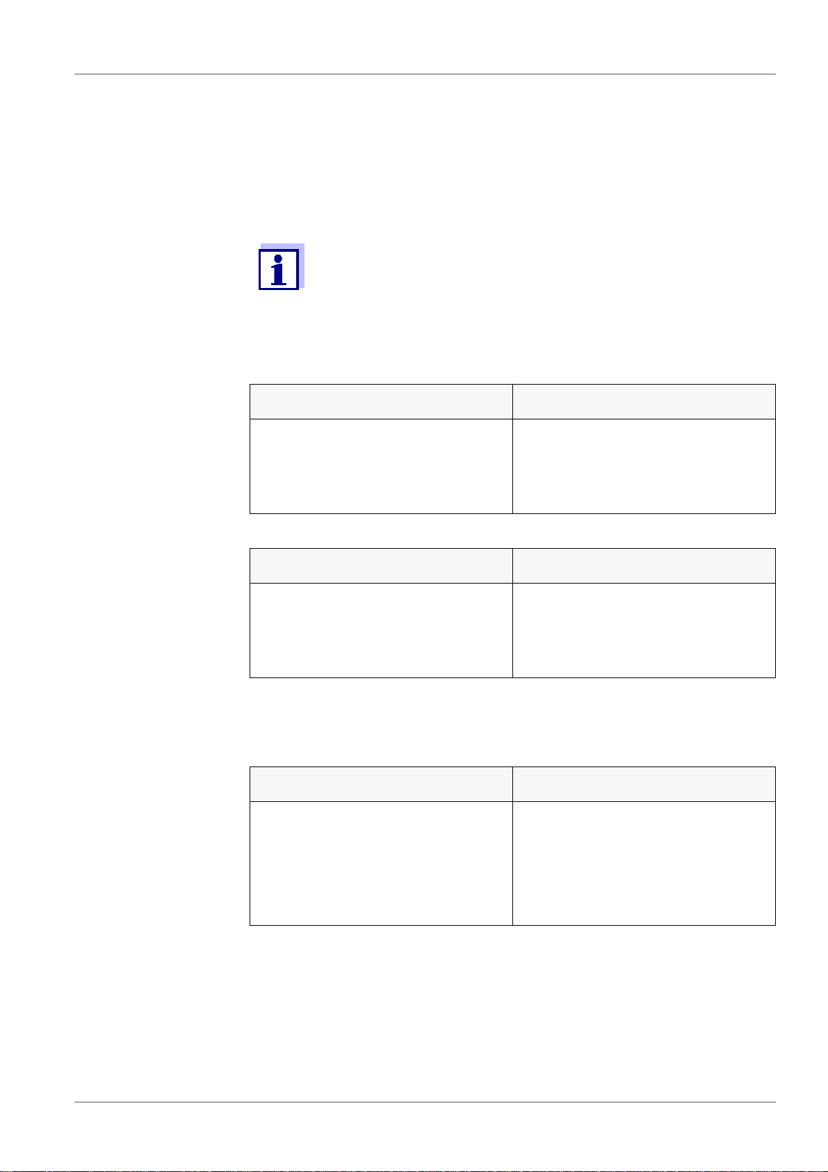
10.1.1 No stable measured value
Cause Remedy
• Junction of the electrode contaminated
• Glass membrane of the electrode
contaminated
Cause Remedy
• pH value of the test sample not
stable
• Temperature of the test sample
not stable
10.1.2 Error message CalError
Cause Remedy
• The values determined for zero
point and slope of the electrode
are outside the allowed limits.
• Clean the junction
• Clean the glass membrane
• Measure with air excluded if
necessary
• Adjust temperature if necessary
• Recalibrate
• Junction contaminated • Clean the junction
• pH electrode broken • Replace the pH electrode
38 ba75925e02 12/2011
Page 39

pH 7110 What to do if...
Cause Remedy
• The used buffer solutions do not
agree with the set buffer set
• Buffer solutions too old • Use only once.
• Buffer solutions depleted • Change solutions
10.1.3 Error message OFL, UFL
The measured value is outside the measuring range.
The measured value is obviously incorrect.
Cause Remedy
• Cable broken • Replace the electrode
• Gel electrolyte dried out • Replace the electrode
• Air bubble in front of the junction • Remove the air bubble
• Set different buffer set
or
• Use different buffer solutions
Note the shelf life
• Air in the junction • Extract air or moisten the junction
10.2 ORP
More information and instructions on cleaning and exchange of
sensors are given in the documentation of your sensor.
10.2.1 No stable measured value
Cause Remedy
• Junction contaminated • Clean the junction
• Pt-ORP electrode contaminated • Clean the Pt-ORP electrode
ba75925e02 12/2011 39
Page 40

What to do if... pH 7110
Cause Remedy
• ORP value not stable • Measure with air excluded if
necessary
• Temperature not stable • Adjust temperature if necessary
10.2.2 Error message OFL, UFL
The measured value is outside the measuring range of the meter.
The measured value is obviously incorrect.
Cause Remedy
• Cable broken • Replace the electrode
• Gel electrolyte dried out • Replace the electrode
• Air bubble in front of the junction • Remove the air bubble
• Air in the junction • Extract air or moisten the junction
10.3 General inform ation
10.3.1 Symbol for calibration evaluation flashes
Cause Remedy
Calibration interval expired Recalibrate the measuring system
10.3.2 [LoBat] display
Cause Remedy
Batteries almost empty Replace the batteries (see section
3.3.1 I
NSERTING THE BATTERIES,
page 10)
40 ba75925e02 12/2011
Page 41

pH 7110 What to do if...
10.3.3 Instrument does not react to keystroke
Cause Remedy
Operating condition undefined or
EMC load unallowed
• Processor reset:
Press the <ENTER> and
<On/Off> key simultaneously
10.3.4 Displaying the software version (meter)
Cause Remedy
E. g., a question by the service
department
• Switch on the meter.
During the display test, display
the software version with
<ENTER>.
ba75925e02 12/2011 41
Page 42

Technical data pH 7110
11 Technical data
11.1 Measuring ranges, resolution, accuracy
11.1.1 Measuring ranges, resolution
Parameter Measuring range Resolution
pH - 2.0 ... + 20.0
- 2.00 ... + 20.00
- 2.000 ... + 19.999
U [mV] - 1200.0 ... + 1200.0
- 2000 ... + 2000
T [°C] - 5.0 ... + 105.0 0.1
T [°F] + 23.0 ... + 221.0 0.1
11.1.2 Manual temperature input
Parameter Range Increment
T
T
[°C] - 25 ... + 130 1
manual
[°F] -13 ... + 266 1
manual
0.1
0.01
0.001
0.1
1
42 ba75925e02 12/2011
Page 43

pH 7110 Technical data
11.1.3 Accuracy (± 1 digit)
Temperature of the
Parameter Accuracy
test sample
pH / range
- 2.0 ... + 20.0
- 2.00 ... + 20.00
- 2.000 ... + 19.999
*
± 0.1
± 0.01
± 0.005
+ 15 °C ... + 35 °C
+ 15 °C ... + 35 °C
+ 15 °C ... + 35 °C
U [mV] / range
- 2000 ... + 2000
-1200.0 ... +1200.0
± 1
± 0.3
+ 15 °C ... + 35 °C
+ 15 °C ... + 35 °C
T [°C] / temperature sensor
•NTC 30
• PT 1000
* when measuring in a range of ± 2 pH around a calibration point
± 0.1
± 0.1
11.2 General data
Dimensions Approx. 240 x 190 x 80 mm
Weight Approx. 1.0 kg
Mechanical
Type of protection IP 43
structure
Electrical
Protective class III
safety
Test certifi-
CE, cETLus
cates
Ambient
Storing: - 25 °C ... + 65 °C
conditions
Operation: +5 °C ... + 55 °C
With the power pack connected:
+5 °C ... + 40 °C
Allowable relative humidity
Yearly mean: < 75 %
30 days/year: 95 %
Other days: 85 %
ba75925e02 12/2011 43
Page 44

Technical data pH 7110
Power supply Batteries: 4 x 1.5 V alkali-manganese batteries, type
AA
Operating time: Approx. 2500 h (operating hours)
Rechargeable batteries: 4 x 1.2 V NiMH rechargeable
batteries, type AA
(no charging function)
Power pack: Ktec KSAC 0900110W1UV-1
Input: 100 ... 240 V ~ / 50 ... 60 Hz / 270 mA
Output: 9 V = / 1.1 A
Connection max. Overvoltage category II
Primary plugs included in the scope of delivery: Euro,
US, UK and Australian.
Sensor input Input resistance: > 5 * 1013 ohm
Service interface
Applicable
directives and
standards
Input current: < 1 * 10
-12
A
This interface can be used for service purposes only.
EMC:
• EC directive 2004/108/EC
• EN 61326-1
• EN 61000-3-2
• EN 61000-3-3
• FCC Class A
Instrument safety:
• EC directive 2006/95/EC
• EN 61010-1
• ANSI/UL 61010-1
• CAN/CSA-C22.2 No. 61010-1
IP type of protection:
• EN 60529
44 ba75925e02 12/2011
Page 45

pH 7110 Technical data
FCC Class A Equipment Statement
Note: This equipment has been tested and found to comply with the limits
for a Class A digital device, pursuant to Part 15 of the FCC Rules. These
limits are designed to provide reasonable protection against harmful
interference when the equipment is operated in a commercial
environment. This equipment generates, uses, and can radiate radio
frequency energy and, if not installed and used in accordance with the
instruction manual, may cause harmful interference to radio
communications. Operation of this equipment in a residential area is likely
to cause harmful interference in which case the user will be required to
correct the interference at his own expense.
Changes or modifications not expressly approved by the manufacturer
could void the user‘s authority to operate the equipment.
ba75925e02 12/2011 45
Page 46

Glossary pH 7110
12 Glossary
12.1 pH/ORP
Specialist
term
Asymmetry see zero point
Diaphragm The junction is a porous body in the housing wall of refer-
ence electrodes or electrolyte bridges. It arranges the
electrical contact between two solutions and makes the
electrolyte exchange more difficult. The expression, junction, is also used for ground or junction-less transitions.
Description
Electromotive
force of an
electrode
ORP The ORP is caused by oxidizing or reducing substances
pH value The pH value is a measure of the acidic or basic effect of
Slope The slope of a linear calibration function.
Zero point The zero point of a pH combination electrode is the pH
The electromotive force U of the combination electrode is
the measurable electromotive force of an electrode in a
solution. It equals the sum of all the galvanic voltages of
the electrode. Its dependency on the pH results in the
electrode function, which is characterized by the parameters, slope and zero point.
dissolved in water if these substances become effective
on an electrode surface (e. g. a gold or platinum surface).
an aqueous solution. It corresponds to the negative
decadic logarithm of the molal hydrogen ions activity
divided by the unit of the molality. The practical pH value is
the value of a pH measurement.
value at which the electromotive force of the pH combination electrode at a specified temperature is zero. Normally,
this is at 25 °C.
46 ba75925e02 12/2011
Page 47

pH 7110 Glossary
12.2 General inform ation
Specialist term Description
Adjusting To manipulate a measuring system so that the relevant
value (e. g. the displayed value) differs as little as possible from the correct value or a value that is regarded
as correct, or that the difference remains within the
tolerance.
AutoRange Name of the automatic selection of the measuring
range.
Calibration Comparing the value from a measuring system (e. g.
the displayed value) to the correct value or a value that
is regarded as correct. Often, this expression is also
used when the measuring system is adjusted at the
same time (see adjusting).
Measured parameter
Measured value The measured value is the special value of a measured
Molality Molality is the quantity (in Mol) of a dissolved sub-
Potentiometry Name of a measuring technique. The signal (depend-
Reset Restoring the original condition of all settings of a mea-
Resolution Smallest difference between two measured values that
The measured parameter is the physical dimension
determined by measuring, e. g. pH, conductivity or
D.O. concentration.
parameter to be determined. It is given as a combination of the numerical value and unit (e. g. 3 m; 0.5 s;
5.2 A; 373.15 K).
stance in 1000 g solvent.
ing on the measured parameter) of the electrode is the
electrical potential. The electrical current remains constant.
suring system.
can be displayed by a meter.
Stability control
(AutoRead )
ba75925e02 12/2011 47
Function to control the measured value stability.
Page 48

Glossary pH 7110
Specialist term Description
Standard solution The standard solution is a solution where the measured
value is known by definition. It is used to calibrate a
measuring system.
Temperature
function
Name of a mathematical function expressing the temperature behavior of a test sample, a sensor or part of a
sensor.
Test sample Designation of the test sample ready to be measured.
Normally, a test sample is made by processing the original sample. The test sample and original sample are
identical if the test sample was not processed.
48 ba75925e02 12/2011
Page 49

pH 7110 Index
13 Index
A
AR . . . . . . . . . . . . . . . . . . . . . . . . . . . . . . . 14
AutoCal . . . . . . . . . . . . . . . . . . . . . . . . . . . 20
Automatic switch-off function . . . . . . . . . . . 32
AutoRead . . . . . . . . . . . . . . . . . . . . . . . 18, 27
B
Battery compartment . . . . . . . . . . . . . . 11, 36
Buffer sets (pH) . . . . . . . . . . . . . . . . . . . . . 30
C
Calibration evaluation (pH) . . . . . . . . . . . . 25
Calibration interval (pH) . . . . . . . . . . . . . . . 31
ConCal . . . . . . . . . . . . . . . . . . . . . . . . . . . . 22
D
Default (calibration values) . . . . . . . . . . . . 34
Default (measurement settings) . . . . . . . . . 35
Default (system settings) . . . . . . . . . . . . . . 35
Display . . . . . . . . . . . . . . . . . . . . . . . . . . . . 14
Stability control . . . . . . . . . . . . . . . . . . 18, 27
Z
Zero point (pH electrode) . . . . . . . . . . . 19, 24
Zero point, pH . . . . . . . . . . . . . . . . . . . . . . 25
I
Initial commissioning . . . . . . . . . . . . . . . . . 10
Initialize . . . . . . . . . . . . . . . . . . . . . . . . . . . 34
K
Keys . . . . . . . . . . . . . . . . . . . . . . . . . . . . . . 13
M
Measured value display . . . . . . . . . . . . . . . 16
Measuring (ORP) . . . . . . . . . . . . . . . . . . . . 27
Measuring (pH) . . . . . . . . . . . . . . . . . . . . . 18
R
Reset . . . . . . . . . . . . . . . . . . . . . . . . . . . . . 34
Resolution setting . . . . . . . . . . . . . . . . . . . 32
S
Safe operation . . . . . . . . . . . . . . . . . . . . . . . 9
Scope of delivery . . . . . . . . . . . . . . . . . . . . 10
Single-point calibration (pH, AutoCal) . . . . 21
Slope (pH electrode) . . . . . . . . . . . . . . 19, 24
Slope, pH . . . . . . . . . . . . . . . . . . . . . . . . . . 25
Socket field . . . . . . . . . . . . . . . . . . . . . . . . 15
ba75925e02 12/2011 49
Page 50

Index pH 7110
50 ba75925e02 12/2011
Page 51

Page 52

Wissenschaftlich-Technische Werkstätten GmbH
Dr.-Karl-Slevogt-Straße 1
D-82362 Weilheim
Germany
Tel: +49 (0) 881 183-0
+49 (0) 881 183-100
Fax: +49 (0) 881 183-420
E-Mail: Info@WTW.com
Internet: http://www.WTW.com
 Loading...