

Page 1
Manual
MJK Comtroller 702
Effective for software version 83XXXX
COMLI PROTOKOL
Unit ID:
Serial no.:
M702GB/0110 Rev. 111001
As our products are developed continuously, we reserve the right
to make any change in dimensions and specifications.
Page 2

CE - CERTIFICATE OF CONFORMITY
This product complies with the requirements concerning electromagnetic compatibility (EMC) stipulated in
Council directive no. 89/336/EEC of 3rd May 1989, altered at directive no. 92/31/EEC, on the
approximation of the laws of the Member States relating to electromagnetic compatibility.
We declare that the product complies to the values stipulated in EN 50081-1 and EN 50082-1.
M702GB/0110 Rev. 111001
2
Page 3

ComTroller 702
Contents
1 General .................................................5
1.2 MJK-Link™ ...................................................5
2 Operation .............................................. 6
3 Menus ................................................... 8
3.1 F0 - Unit type/ID, software version, clock and
protocol type .................................................8
3.2 F1 - Inputs on/off ........................................... 8
3.3 F2 - Outputs on/off........................................8
3.4 F3 - Limits high/low .......................................8
3.5 F4 - Analog inputs # ...................................... 8
3.6 F5 - Analog input scaled ................................8
3.7 F6 - Counter .................................................9
3.8 F7 - Hour ...................................................... 9
3.9.1 F8.1 - Alarm List ........................................... 9
3.9.2 F8.2 Alarm # ................................................. 9
3.10 F9.1 Storm flow volume.................................9
3.11 F9.2 Storm flow calculation ...........................9
4 Main functions ...................................10
4.1 Choose language ........................................10
4.2 Set time and date .......................................10
4.3 Password enabled/disabled ......................... 10
4.4 Summer time / winter time .......................... 10
4.5 Enter password ........................................... 10
4.6 Analog inputs averaging...............................10
4.7 Data logging interval (MM:SS) ...................... 10
4.8 Tone or pulse dialing .................................... 10
4.9 Telephone call at power failure ..................... 10
4.10 Number of incoming rings before answer ..... 10
4.11 Unit ID no. for Comtroller ............................. 10
4.12 Automatic reset of alarms............................ 10
4.13 Telephone number ...................................... 10
4.14 SMSC telephone numbers .......................... 10
4.15 Master or Slave ........................................... 10
6 Digital inputs ..................................... 12
6.1 Digital input # .............................................. 12
6.2 Alarm / in use .............................................. 12
6.3 Signal delayed ............................................. 12
6.4 NO / NC ..................................................... 12
6.5 Alarm - call by telephone ............................. 12
7 Digital outputs ................................... 12
7.1 Digital output # ............................................ 12
7.2 NO / NC ..................................................... 12
7.3 Time / Fixed ................................................ 12
7.4 Time before start ......................................... 12
7.5 Set ON-time ............................................... 12
7.6 Special functions for the digital outputs ........ 12
8 Interlock .............................................. 13
8.1 Interlock in use yes/no ................................ 13
8.2 Start of interlock .......................................... 13
8.3 Stop interlock .............................................. 13
8.4 Interlock on receivers output # ....................13
8.5 Receivers telephone number ....................... 13
8.6 Receivers output # ...................................... 13
9 Pump control ..................................... 13
9.1 Pump control activated YES / NO ............... 13
9.2 Pump control EMPTYING / FILLING ............ 13
9.3 Pump control DO 2 ACTIVE ........................ 13
9.4 Pump alternation YES / NO ......................... 13
9.5 Level 2 in use YES / NO .............................. 13
9.6 Pump control start level ...............................13
9.7 Pump control start level ...............................13
10 Telephone list for alarms .................. 14
10.1 Telephone number 1-9 ................................ 14
10.2 Key In PS Message .....................................14
10.3 Entering SMS messages ............................. 14
5 Analog inputs ....................................11
5.1 Analog input # ............................................. 11
5.2 Input no 1 0 - 20 / 4 / 20 mA ...................... 11
5.3 Input no 1 scaled 0 / 4 mA ..........................11
5.4 Input no 1 scaled 20 mA ............................. 11
5.5 High limit yes / no ........................................11
5.6 Set high limit ...............................................11
5.7 High limit alarm / in use ............................... 11
5.8 High limit - signal delayed ............................ 11
5.9 High alarm - call by telephone ..................... 11
5.10 Low limit yes / no ........................................ 11
5.11 Set low limit................................................. 11
5.12 Low limit alarm / in use ................................ 11
5.13 Low limit - signal delayed............................. 11
5.14 Low limit - call by telephone ........................ 11
M702GB/0110 Rev. 111001
11 Programming of storm flow
calculation .......................................... 15
11.1 Stormflow calculation .................................. 15
11.2 Stormflow calculation in use Yes/no ............. 15
11.3 Zero-point DI # ............................................ 15
11.5 Key in the number of Q(h) points (1-9).......... 15
11.6 Key in the level mark ................................... 15
11.7 Key in the flow mark ................................... 15
12 Combi alarms ..................................... 15
12.1 Combi alarm # ............................................ 15
12.2 Combi alarm in use ..................................... 15
12.3 Combi alarm signals .................................... 15
12.4 Signal delay ................................................. 15
12.5 Combi alarm calls ........................................ 15
MJK Automation A/S
3
Byageren 7
2850 Nærum
Tlf: 45 56 06 56
Fax: 45 56 06 46
Page 4

ComTroller 702
13 Alarms ................................................. 16
13.1 Operational or alarm signal .......................... 16
13.2 Alarm calls .................................................. 16
13.3 Reset of alarms ........................................... 16
13.4 Special factory codes .................................. 16
13.5 Access code ............................................... 16
13.6 Setting up the serial port ............................. 16
13.7 Forced reset to factory settings ...................16
13.8 SMSC telephone numbers .......................... 16
14 Other information ..............................17
14.1 Specifications ..............................................17
14.2 Maintenance ............................................... 17
15 Electrical connection .......................... 18
15.1 Digital inputs ................................................ 18
15.2 Analog inputs .............................................. 18
15.3 Serial ports .................................................. 18
15.4 External 15 V DC supply .............................. 18
15.5 Software upgrade........................................ 18
16 Factory settings ................................. 20
M702GB/0110 Rev. 111001
4
Page 5
ComTroller 702
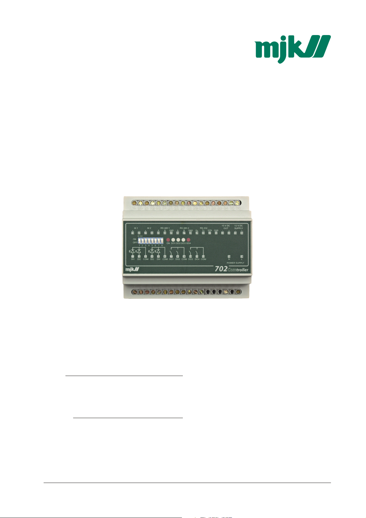
1 General
MJK Comtroller 702 is developed for control and
surveillance of small pumping stations and water
borings. Comtroller 702 is a complete unit with inand outputs, CPU, data logger, real time clock and
communications port for data transmission on
owned lines.
Comtroller 702 is an advanced product based on
the experience from the thousands of monitoring
systems delivered during the past 15 years.
Comtroler 702 is an advanced product for on-site
mounting with control, data logging storing and
transmission of analog and digital measuring values
to be used in both small and large SCADA systems.
Comtroller 702 is typically arranged in clusters
where each Comtroller is connected to a 2-wire
communications line. A Data Transmitter 795 is
then connected as a master communications unit.
Every single Comtroller 702 can be called
individually by their different ID numbers, and the
Data Transmitter 795 simply handles the data
transmission via a telephone modem, a radio
transceiver or a GSM modem directly to the
SCADA system.
Comtroller 702 has all necessary functions built in
such as interface to measuring and control
equipment, a data logger, counters and data
transmission. Comtroller 702 is programmed directly
from a PC, from the SCADA system or via a MJK
Data Transmitter 795 as a master communications
unit.
Comtroller 702 is a compact unit containing all
necessary functions such as communications interface and drivers, software, I/O ports, data storage
memory and RS485 repeater.
Comtroller 702 is simple and economic to utilize
since it contains all necessary facilities to decrease
the number of external components needed to
form a complete unit for control, monitoring and
data transmission.
The RS 232 port is used for interconnection
through external modems, GSM-modems or a PC
for configuring or data readout.
1.2 MJK-Link™
The MS-Windows™-based program MJK-Link™
can be used for monitoring one or more Comtroller
702. It is possible with MJK-Link™ via a PC with a
modem to read realtime values, stored values for
investigation of storm flows and changing of
setpoints.
This manual deals with MJK Comtroller 702 with
Comli-protocol for telephone modems. GSMmodems, RS 485 on owned lines, powerline
modems and closed radio networks.
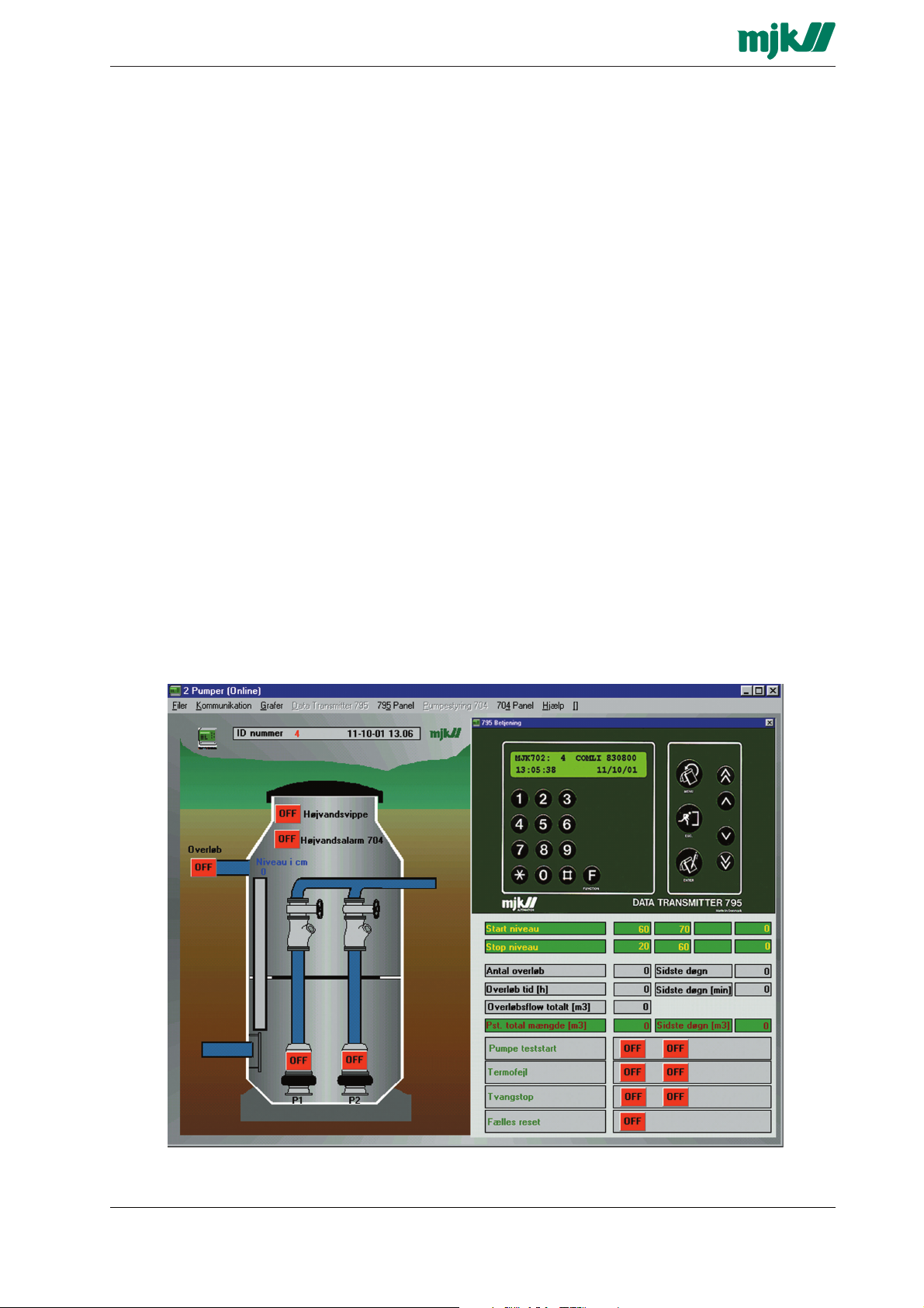
Screen dump from the monitoring program MJK-Link™, where a pumping station with 2 pumps, monitored and
controlled by a Comtroller 702 are operated in a window that appears as the well-known MJK Data Transmitter 795.
MJK Automation A/S
M702GB/0110 Rev. 111001
5
Byageren 7
2850 Nærum
Tlf: 45 56 06 56
Fax: 45 56 06 46
Page 6
ComTroller 702
2 Operation
A Comtroller 702 can be considered as a Data
Transmitter 795 without display and keypad and
with a built-in pump controller. Instead of display
and keypad the Comtroller 702 is operated via the
serial communications port from either a PC with
MJK-Link™ or a Data Transmitter 795.
MJK-Link™ is used for monitoring and operation of
Comtroller 702. The Comtroller 702 will appear
exactly as a Data Transmitter 795 in MJK-Link™
with its well-known 2 x 24 character display and
keypad. The kepad is simply operated via the PC
keyboard.
MJK-Link™ makes it possible to upload,
download and save the settings for one or more
Comtroller 702's interconnected on the same multidrop communications æline. It is thus possible to
download the setting from Comtroller no. 9, save
the setting as i.e. "Pumping station at the bend"
and upload the setting to Comtroller no. 14, placed
at "Pumping station at the pond". It is also possible
to name the in- and outputs individually.
A Data Transmitter 795 with Master-software can
also be used to operate a number of Comtroller
702's on the same multidrop communications line.
The desired Comtroller 702 is selected by entering
the corresponding ID-number on the Data Transmitter 795, after which the selected Comtroller can
be operated exactly as if it were a Data Transmitter
795. At the same time the Data Transmitter 795
contains a surveillance function that calls the
Comtrollers one by one over an adjustable interval.
If a Comtroller does not respond, the Data transmitter will send a system alarm.
A Data Transmitter 795 also manages
comunication to the SCADA system, MJK-Link™
etc.
A typical installation covers five to 20 Comtrollers in
an area where communication takes place via
owned lines or with MJK PowerLine modems
through the mains supply network.
On ie. the main pumping station, a Data Transmitter 795 with master software is installed, which will
be able to send alarms via a telephone- or GSM
modem to the SCADA system and/or one or more
mobile telephones as SMS messages.
M702GB/0110 Rev. 111001
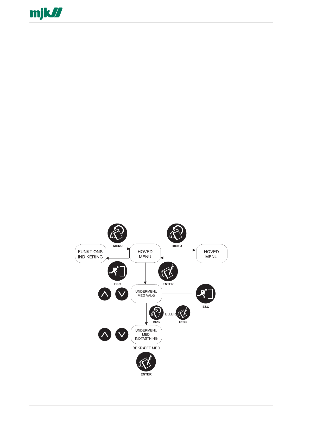
The figure shows an overview of the functional buttons and their general function.
6
Page 7
ComTroller 702
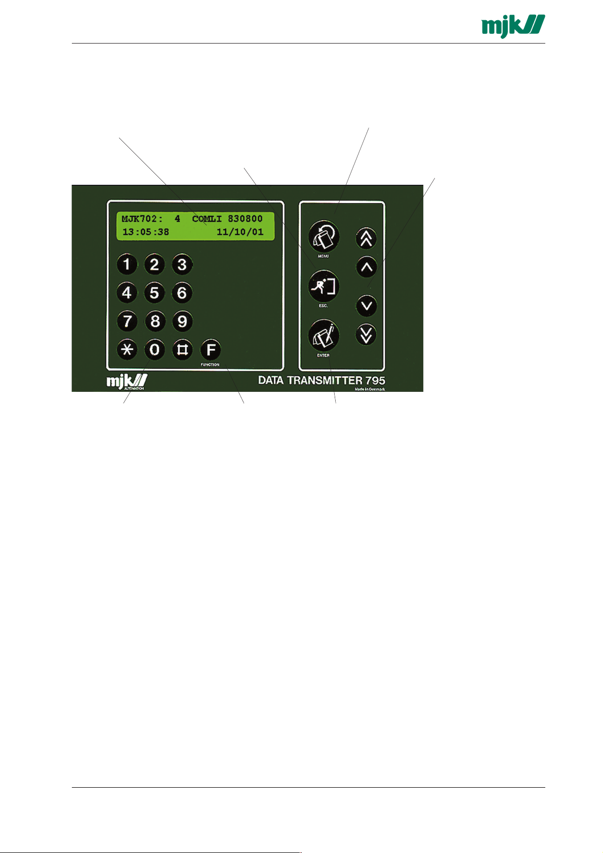
Display
2 x 24 character backlit
display for indication of
programming menus,
measuring values alarms
etc.
ESC.-key
This key changes back to
the previous menu or
cancels a selection. By
pressing the ESC.-key 2-3
times you will always
return to the functional
indication.
MENU
The MENU key are used to
switch between main
menus and submenus.
Arrow keys
The arrow keys are used
for altering the current
setting. In a submenu with
selections, the top line
shows the current setting
and the bottom line shows
the alternative setting (in
brackets). The arrow keys
are used to scroll between
the selections. The arrow
keys also alters the inand output no. By
activating the key, the
number in the display will
increase. By Activating the
key the number will
decrease.
Numerical keys
The keys 0-9,# and * are
used for configuring
telephone numbers,
delays, analog scaling etc.
Function key F
The function key is used
for selecting which
functional indication to
show on the display, e.g.
F0.
ENTER
Press ENTER to change
from a main menu to a sub
menu, as well as between
sub menus. Any choice
made in the sub menus
must be confirmed by
pressing ENTER.
M702GB/0110 Rev. 111001
MJK Automation A/S
7
Byageren 7
2850 Nærum
Tlf: 45 56 06 56
Fax: 45 56 06 46
Page 8

ComTroller 702
3 Menus
3.1 F0 - Unit type/ID, software version, clock
and protocol type
Menu F0 show the MJK unit type, protocol type,
program version and date / time.
MJK 702 : 3 COMLI 830802
16:07:29 24/10/01
In above example, the Data Transmitter is
connected to a Comtroller 702 with unit ID no. 3.
The Unit ID no. is set binary by means of 8
switches on the front panel. (All OFF = 0 - All ON =
255.) Note! The unit ID no. must be set within the
range 1 to 247.
3.2 F1 - Inputs on/off
In menu F1 is shown whether the digital inputs are
ON or OFF.
INPUTS 1 2 3 4
ON : OFF:
The first two fields indicate if the high limits are
exceeded and the last two show if the low limits
are exceeded.
LIMITS HIGH/LOW 1 2
3 4 5 6 1 2
ON : OFF:
A delay time can be set individually for each analog
input allowing the input to exceed the limit
momentarily without i.e. activating an alarm. (See
section 5.)
If the analog input are within limits, the field will be
empty. If the limits are exceeded, the field will flash
during the delay time. When the delay time has
expired, the field is shown in a steady state.
3.5 F4 - Analog inputs #
Menu F4 shows the immediate value of an analog input as a horizontal bar formed of up to 24 fields. If the
input signal is 4 (0) mA (see also section 5.2), none of
the fields is lit (0 %). If the input signal is 20 mA, all 24
fields is lit (100 %).
In above example, DI no. 1 and 2 are ON while DI
3 and 4 are OFF.
A delay time can be set individually for each digital
input in order to allow the input to go ON without
activating i.e. an alarm. (See section 6.)
When the input is OFF an empty field is shown.
When the input is ON, the field will flash for the
duration of the delay time. When the delay time
has expired, a full field will be lit.
3.3 F2 - Outputs on/off
Menu F2 show the status of the digital outputs.
OUTPUTS 1 2 3 4
ON : OFF:
In above example, DO no. 1 and 2 are ON while
DO 3 and 4 are OFF.
A delay time can be set individually for each digital
output in order to delay the activation of the
corresponding output relay. (See section 7.)
When the output is OFF an empty field is
shown. When the output is ON the field will flash
for the duration of the delay time. When the delay
time has expired, the output relay is activated and
the field will be shown in a steady state .
ANALOG INPUT NO #
Select the desired analog input with the arrow
keys or by keying the corresponding input number
(1 - 2).
3.6 F5 - Analog input scaled
Menu F5 shows the immediate value of an analog
input in digits rather than a horizontal bar as in the
previous menu.
The first set of digits read out the signal value as
the percentage between the low mA value (0/4
mA) (see also section 5.2) and the high mA value
(20 mA). The next set of digits read out the same
signal multiplied with a programmable scaling factor.
The readout scaling is determined by programming
the desired readout range corresponding to the
low mA value (0 / 4 mA) and the high mA value (20
mA) respectively. If e.g. a tank level is measured,
and the level varies between 2 metres and 3
metres, the low mA value is set to correspond to
"200" and the high mA value is set to "300". A level
measurement of i.e. 2,5 metres will corespond to a
signal value of 50 %, resulting in a readout of "250"
(See section 5.3 - 5.4)
3.4 F3 - Limits high/low
Menu F3 indicate if the high and low limits for the
analog inputs are exceeded.
M702GB/0110 Rev. 111001
ANALOG INPUT NO #
50 % SKALERET 250
Select the desired analog input with the arrow
keys or by keying the corresponding input number
(1 - 2).
8
Page 9

ComTroller 702
3.7 F6 - Counter
Menu F6 shows how many times a digital input or
an analog high or low limit has been set ON.
COUNTER DI #
RESET: ENTER 257
Every single input / high and low limit has its own
counter. Use the arrow keys to change the readout
between:
- digital input 1 - 4
- analog input high limit 1 - 2
- analog input low limit 1 - 2
(Pressing key 1 to 4 will change the display readout directly to digital input 1 to 4.)
If the ENTER button is keyed, the counter present
in the display - and only this - will be reset.
3.8 F7 - Hour
Menu F7 show the total time the digital inputs and
the analog high limits and low limits have been set
ON.
The ON time is registered continuously; meaning
that if an input or limit is set to OFF and later is set
back to ON, the timer continues from its previous
value.
HOUR : AI # LOW
RESET: ENTER 2:43
Every single input / high and low limit has its own
counter. Use the arrow keys to change the readout
between:
- digital input 1 - 4
- analog input high limit 1 - 2
- analog input low limit 1 - 2
(Pressing key 1 to 4 will change the display readout directly to digital input 1 to 4.)
ALARM NO 1 2 3 4 5 6 7 8 9
A flashing field indicates that the alarm is ON, an
empty field indicates that the alarm is OFF, and
a steady field indicates that the alarm has been
reset.
All alarms in the list will be reset by pressing
ENTER.
3.9.2 F8.2 Alarm #
By depressing an arrow key or 1-9, menu F8.2 will
appear displaying the input number and type
causing the alarm, the corresponding alarm designation, the immediate status of the alarm and the
time when the alarm was set.
ALARM # : AI 2 LAV
START 15:23:1724/12/95
Use either the arrow keys to scroll through the
alarm list or 1 to 9 to jump directly to the desired
alarm number.
The alarm shown in the display will be reset by
pressing ENTER.
Menu F8.1 will reappear by repetitous depressing
of the arrow keys or 0.
3.10 F9.1 Storm flow volume
Menu F9 display the volume of the overflow. The
volume meter is reset by depressing ENTER
STORM FLOW VOLUME
RESET: ENTER 1204 m
3
3.11 F9.2 Storm flow calculation
Menu F9.2 display the immediate flow.
If the ENTER button is keyed, the counter present
in the display - and only this - will be reset.
3.9.1 F8.1 - Alarm List
Menu F8.1 show a list of the last 9 alarms and their
immediate status.
Whenever an alarm occurs, it will be registered as
alarm no. 1 and all other alarms in the list is moved
one place to the right. Furthermore, the previous
alarm no. 9 will be erased and also be
automatically reset if it has not already been reset
manually via the Data Transmitter keypad or via
the SCADA system. Also, an alarm deriving from a
specific input has to be reset before a new alarm
from that input will be put in the list.
M702GB/0110 Rev. 111001
STORM FLOW CALCULATION
FLOW RATE 12.40 m
9
3
/t
MJK Automation A/S
Byageren 7
2850 Nærum
Tlf: 45 56 06 56
Fax: 45 56 06 46
Page 10

ComTroller 702
4 Main functions
4.1 Choose language
The desired language is chosen using the arrow
keys - confirm with ENTER.
4.2 Set time and date
The time and date can be set using the arrow keys
or the numerical keys. Confirm the changes with
ENTER or press MENU if no changes are desired.
4.3 Password enabled/disabled
If password protection is enabled, a code must be
keyed in before access is given to the menus with
the MENU key.
If a password is desired, it must be keyed in
before the system can be set up.
Use the arrow keys to select and confirm with
ENTER.
4.4 Summer time / winter time
Select summer time or winter time with the arrow
keys and confirm the selection with ENTER.
4.5 Enter password
Enter the password number with the numerical
keys and confirm with ENTER.
4.6 Analog inputs averaging
Every second the value of the analog inputs are
registered, and for every 5 minutes the analog
values are logged. If averaging is wanted, a mean
of all the 1 sec. registrations for the last 5 minutes
is logged. If averaging is not wanted, the current
analog value is logged.
Use the arrow keys to select and press ENTER to
confirm.
that would be caused by very short voltage
failures.
This function is only available if the Comtroller is
supplied from an external 12 V DC source with
battery backup.
Use the arrow keys to select and confirm with
ENTER.
4.10 Number of incoming rings before answer
Select the number of rings before the Comtroller
702 should answer a call. The number of rings can
be set between 1 and 5. Use the arrow keys to
select and confirm with ENTER.
4.11 Unit ID no. for Comtroller
In this menu the Unit ID no. of the current
Comtroller is displayed. The Unit ID no. is used to
identify the different Comtroller 702's that may be
interconnected through the same multidrop line.
The Unit ID no. is set binary by means of 8
switches on the front panel. (All OFF = 0 - All ON =
255.)
Note! The unit ID no. must be set within the range
1 to 247.
4.12 Automatic reset of alarms
Select whether an active alarm should be reset
automatically if (1) the alarm cause disappears
before the alarm are transmitted or (2) the alarm is
not reset from the SCADA terminal. Use the arrow
keys to select and confirm with ENTER.
4.13 Telephone number
Enter the number of the telephone line to which the
Comtroller is connected. The telephone number is
used as ID-number when SMS alarms are
transmitted.
4.7 Data logging interval (MM:SS)
The data logging interval are used for the
enhanced logging function that stores the values
from the analog inputs. The logging interval can be
selected in the following fixed intervals: 30 sec.
(00:30), 1 min. (01:00), 5 min. (05:00), 10 min.
(10:00), 30 min. (30:00), and 60 min. (60:00).
Use the arrow keys to select and press ENTER to
confirm.
4.8 Tone or pulse dialing
Select whether the telephone call is to be carried
out with tone or pulse signals.
Use the arrow keys to select and confirm with
ENTER.
4.9 Telephone call at power failure
If this function is selected, the Comtroller will dial
the first number on the telephone list (see section
10) if the mains supply disappears for more than 30
seconds. The 30 second delay avoids alarm calls
M702GB/0110 Rev. 111001
Key in the number and confirm with ENTER.
This function is only available if a modem is
connected.
4.14 SMSC telephone numbers
In order to make the Comtroller able to transmit
SMS messages, the SMS message must be dialed
to a particular SMSC server. See section 10 for
telephone numbers to SMSC-servers.
Key in the number and confirm with ENTER.
This function is only available if a modem is
connected.
4.15 Master or Slave
Select whether the Comtroller 702 should act as a
Master or a Slave on the multidrop
communications line.
Use the arrow keys to select and confirm with
ENTER.
10
Page 11

ComTroller 702
5 Analog inputs
5.1 Analog input #
Select the input to be set by pressing 1. Confirm
with ENTER.
5.2 Input no 1 0 - 20 / 4 / 20 mA
Select if the signal range for the analog input
should be either 0 - 20 mA or 4 - 20 mA.
Use the arrow keys to select and confirm with
ENTER.
5.3 Input no 1 scaled 0 / 4 mA
Set the equivalent of the low mA value. If i.e. "200"
is entered, the display will read out "200" at an input value of 0 / 4 mA. Use the arrow keys or the
numeric keys and confirm with ENTER.
5.4 Input no 1 scaled 20 mA
Set the equivalent of the high mA value. If i.e.
"300" is entered, the display will read out "300" at
an input value of 20 mA. Use the arrow keys or the
numeric keys and confirm with ENTER.
5.5 High limit yes / no
Select if exceeding the high limit setting on the
analog input should be registered.
Use the arrow keys to select and confirm with
ENTER.
5.10 Low limit yes / no
Select if exceeding the low limit setting on the analog input should be registered.
Use the arrow keys to select and confirm with
ENTER.
5.11 Set low limit
Set the low limit that the analog input should
exceed before the event is registered.
Use the arrow keys to select and confirm with
ENTER.
5.12 Low limit alarm / in use
See section 13.1 for a description between "Limit
alarm" and "In use".
Use the arrow keys to select and confirm with
ENTER.
5.13 Low limit - signal delayed
Set the delay time that the input can exceed the
high limit setting without an alarm is being
activated. The format for the delay period is
MM:SS.
In the case of a power failure the analog input will
detect 0 mA. If analog low limit is set to ALARM
simultaneously with a alarm call at power failure
(see section 4.9), the delay time of the low limit
must be set to more than 30 sec.
5.6 Set high limit
Set the high limit that the analog input should
exceed before the event is registered.
Use the arrow keys to select and confirm with
ENTER.
5.7 High limit alarm / in use
See section 13.1 for a description between "Limit
alarm and In use".
Use the arrow keys to select and confirm with
ENTER.
5.8 High limit - signal delayed
Set the delay time that the input can exceed the
high limit setting without an alarm is being
activated. The format for the delay period is
MM:SS.
Use the arrow keys (double arrow for minutes and
single arrow for seconds) or the numeric keys and
confirm with ENTER.
5.9 High alarm - call by telephone
Select whether an activated high limit alarm is to
set off a telephone call.
Use the arrow keys (double arrow for minutes and
single arrow for seconds) or the numeric keys and
confirm with ENTER.
5.14 Low limit - call by telephone
Select whether an activated low limit alarm is to
set off a telephone call.
Use the arrow keys to select and confirm with
ENTER.
Use the arrow keys to select and confirm with
ENTER.
M702GB/0110 Rev. 111001
11
MJK Automation A/S
Byageren 7
2850 Nærum
Tlf: 45 56 06 56
Fax: 45 56 06 46
Page 12

ComTroller 702
6 Digital inputs
6.1 Digital input #
Use the arrow keys or enter 1 to 4 to select the input to be programmed.
6.2 Alarm / in use
See section 13.1 for a description between "Limit
alarm" and "In use".
Use the arrow keys to select and confirm with
ENTER.
6.3 Signal delayed
Set the delay time the input can be ON without an
alarm is being activated.
The format for the delay period is MM:SS.
Use the arrow keys (double arrow for minutes and
single arrow for seconds) or the numeric keys and
confirm with ENTER.
6.4 NO / NC
Select the input as normally open (NO) or normally
closed (NC). At NO the input is ON when the
power is connected; at NC the input is ON when
the power is disconnnected.
Use the arrow keys to select and confirm with
ENTER.
6.5 Alarm - call by telephone
Select if a digital input is to set off a telephone call
when going ON.
Use the arrow keys to select and confirm with
ENTER.
7 Digital outputs
7.1 Digital output #
Use the arrow keys or enter 1 to 4 to select the
output to be programmed.
7.2 NO / NC
Select the relay function to normally open (NO) or
normally closed (NC). At NO the relay switch will
go ON when the output is activated; at NC the
relay switch will go OFF when activated.
Use the arrow keys to select and confirm with ENTER.
At power failure all the outputs will go OFF.
7.3 Time / Fixed
A time controlled output is only ON for a certain
period of time (the ON-time) whereafter it goes
OFF. A fixed output which is turned ON must
receive a command in order to set the output OFF.
Use the arrow keys to select and confirm with
ENTER.
7.4 Time before start
Enter the delay time before start - which is the time
passing from an ON-command is transmitted until
the output responds.
The format for the delay period is MM:SS.
Use the arrow keys (double arrow for minutes and
single arrow for seconds) or the numeric keys and
confirm with ENTER.
7.5 Set ON-time
Enter the ON-time for the output. The On-time is
the period of time the output is turned ON if the
output is set to "time controlled".
The format for the delay period is MM:SS.
Use the arrow keys (double arrow for minutes and
single arrow for seconds) or the numeric keys and
confirm with ENTER.
7.6 Special functions for the digital outputs
(This menu is only accessible if 'Fixed' is selected
as described in section 7.3.)
It is possible to perform AND logic sequences by
means of the digital in- and outputs.
For example the Comtroller 702 can be programmed to activate a digital output when 2 digital
inputs are ON. The digital signals can also derive
from exeeding a limit value on an analog input - or
a combination of a signal caused by exceeding a
limit value and an active digital input.
The following signals can be combined:
- digital input 1 - 4
- analog limit HIGH 1 - 2
- analog limit LOW 1 - 2
- combi alarm 1 - 8
M702GB/0110 Rev. 111001
12
Page 13

ComTroller 702
8 Interlock
When interlocking two MJK Comtroller 702's they
will communicate with one another. In this way one
data transmitter can control a digital output
remotely on the other.
8.1 Interlock in use yes/no
Select whether the interlock function is to be used
or not.
Use the arrow keys to select and confirm with
ENTER.
8.2 Start of interlock
Select the signal which - when it goes ON - will
make the Comtroller call the other Comtroller and
set an output ON.
Use the arrow keys to select and confirm with
ENTER.
The following signals can be selected:
- digital input 1 - 4
- analog limit HIGH 1 - 2
- analog limit LOW 1 - 2
- combi alarm 1 - 8
As long as the signal is ON, calls will take place in
10 minutes interval. The remote controlled output
must therefore be set to "time controlled" and
configured with an ON-time of more than 10
minutes (e.g. 15 min.), thus securing that the output is not constantly ON if an error situation should
occur (e.g. a broken telephone cable). This way
the output is certain to go OFF even in the case of
communication failure.
At faultless communication the ON time of the
remote controlled output will be initialised at each
call and the remote controlled output will stay ON
as long as the controlling signal is active.
8.3 Stop interlock
Select the signal which - when it goes ON - will
make the Comtroller call the other Comtroller and
set an output ON.
Use the arrow keys to select and confirm with
ENTER.
The following signals can be selected:
- digital input 1 - 4
- analog limit HIGH 1 - 2
- analog limit LOW 1 - 2
- combi alarm 1 - 8
Only one call attempt will be made. If the same
signal is chosen both as start and finish condition
for the inter lock, the finish condition will be when
the signal goes OFF.
8.4 Interlock on receivers output #
Select which digital output of the remote Comtroller
is to be controlled.
Use the arrow keys to select and confirm with
ENTER.
8.5 Receivers telephone number
Enter the ID number of the remote Comtroller and
confirm with ENTER or start press ENTER to
correct a number already keyed in.
If Powerline modems, radio modems, or the RS485
port are used, the ID number of the remote
Comtroller should also be used.
8.6 Receivers output #
Select which output on the remote Comtroller to
be controlled.
Use the arrow keys to select and confirm with ENTER.
9 Pump control
9.1 Pump control activated YES / NO
Select if the pump controller should be activated.
Use the arrow keys to select and confirm with
ENTER.
9.2 Pump control EMPTYING / FILLING
Select if output no. 1 or 2 should be configured for
either emptying or filling.
Use the arrow keys to select and confirm with
ENTER.
9.3 Pump control DO 2 ACTIVE
Select if 1 og 2 pumps are used.
Use the arrow keys to select and confirm with ENTER.
9.4 Pump alternation YES / NO
Select if the pumps should alternate. This menu is
only available when 2 pumps are selected in
section 9.2.
Use the arrow keys to select and confirm with ENTER.
9.5 Level 2 in use YES / NO
Select if both pumps may start at the same time.
This menu is only available when 2 pumps are
selected in section 9.2.
Use the arrow keys to select and confirm with ENTER.
9.6 Pump control start level
Set the start level for the pump(s)
Use the arrow keys to select and confirm with ENTER.
9.7 Pump control start level
Set the stop level for the pump(s)
Use the arrow keys to select and confirm with
ENTER.
M702GB/0110 Rev. 111001
13
MJK Automation A/S
Byageren 7
2850 Nærum
Tlf: 45 56 06 56
Fax: 45 56 06 46
Page 14

ComTroller 702
10 Telephone list for alarms
(This section applies is only
10.1 Telephone number 1-9
In this menu up to 9 telephone numbers are keyed
in which will be dialed chronologically at an alarm
situation.
Press key 1 - 9 to select the number which is to be
changed, press ENTER to change the receiver
type (PC, Pager, ph [phone], SMS), press ENTER
to correct the number - key in the number with the
numerical keys, and confirm with ENTER.
After keying in the telephone number the MENU
key must be used in order to move on to the next
menu, the ENTER key will be of no use here.
When calling through a switchboard, a * can be
used for awaiting a dialtone. A * gives a pause of 2
seconds. I.e. 0*00454556,656##23 means:
First dial 0 to get an external line, await the dialling
tone, then dial 0045 45560656, wait for 4 seconds,
then dial 23.
In the parenthesis following the number, it is stated
which type of reciever the call has been made to.
When calling a modem set to 1 [PC]. When calling
a beeper / pager set to 2 [Pager]. When calling an
ordinary telephone set to 3 [PHONE].
10.2 Key In PS Message
If a telephone number has been chosen as a PS
number, a message of up to 8 digits can be typed
in (e.g. the telephone number of the data transmitter), the message can be different for the various
telephone numbers. The message for the pager is
shown in the pager display together with a code
for the alarm, which has caused the call.
E.g. a datatransmitter with telephone number
455660656 where digital input 5 has an active
alarm input; will give the following alarm message
in the PS:
05-45560656
The configuration is stored in a EEPROM which is
not lost even if the supply is disconnected
10.3 Entering SMS messages
Up to 8 characters can be entered here if a receiver type is selected as an SMS type.
It is possible to enter digits as an SMS message
via Data Transmitter 795, and with MJK-Link32™ it
is also possible to enter a text.
The SMS message will be shown on the cellular
phone with "MJK-702" as the opening text,
followed by the cause of the alarm and the
corresponding SMS message. If a GSM modem
are used as communications unit, the pager
message will be changed to an SMS message.
Check the SIM card in a cellular phone if no SMS
message is transmitted, and check, if the phone
number to the SMSC-server is correct. The phone
number to the SMSC-server depends on the GSM
network service provider.
When sending SMS messages and pager
messages, it is not possible to check whether the
message is sent to the recipient or not, since the
messages are delivered to an external server.
The alarm codes are:
01 : Digital input no 1
02 : Digital input no 2
03 : Digital input no 3
04 : Digital input no 4
21 : Analog limit no 1 LOW
22 : Analog limit no 2 LOW
31 : Analog limit no 1 HIGH
32 : Analog limit no 2 HIGH
51 : Combi alarm no. 1
52 : Combi alarm no. 2
53 : Combi alarm no. 3
54 : Combi alarm no. 4
55 : Combi alarm no. 5
56 : Combi alarm no. 6
57 : Combi alarm no. 7
58 : Combi alarm no. 8
90 : Comtroller power failure
M702GB/0110 Rev. 111001
14
Page 15

ComTroller 702
11 Programming of storm flow
calculation
11.1 Stormflow calculation
Comtroller 702 can be applied for calculation of
storm flow by means of one digital and analogue
input. Generally Comtroller 702 is applied to a level
meter with measuring range adapted to the pump
controller. This measuring range is normally
considerably higher, than what is necessary for
flow measurement, generally 10m for the pump
controller and 10-20cm for flow calculation. The
accuracy of the pump controller’s level
measurement is as the whole measuring range.
The data transmitter will compensate by means of
a digital input. An electrode relay, e.g. MJK 501
and a level electrode e.g. MJK 222860 are
applied.
The level electrode is applied where the storm flow
starts. By this, the chosen level meter will be in
zero position and calculate flow on the level signal.
This will improve the accuracy 10 to 15 times in
short term. The system provides a simple and
accurate measurement to a reasonable price.
11.2 Stormflow calculation in use Yes/no
Indicate application of stormflow calculation.
Use the arrow keys and confirm with enter key.
11.3 Zero-point DI #
Indicates the digital input that sets zero-point and
activates the flow calculation.
Choose between AI 1-2
Use the arrow keys, confirm with ENTER.
11.5 Key in the number of Q(h) points (1-9)
Indicate the number of Q/H points for single
linearization of the actual flow. The number can be
set between 1 and 9, as zero-point is set to a flow
3
of 0 m
/h.
12 Combi alarms
It is possible by means of a combi alarm to set off an
alarm call when 2 digital signals is activated
simultaneously. A digital signal can derive from a
digital input or from a limit alarm.
12.1 Combi alarm #
Use the arrow keys or enter 1 to 8 to select the
combi alarm to be programmed.
12.2 Combi alarm in use
Select if the combi alarm should be used. Use the
arrow keys and confirm with ENTER.
12.3 Combi alarm signals
Select the two digital signals to be AND'ed to
activate a combi alarm. The following digital signal
can be selected:
- digital input 1 - 4
- analog limit HIGH 1 - 2
- analog limit LOW 1 - 2
- power failure
12.4 Signal delay
Select the delay for the combilalarm. The delay
time is the time the two digital signals should be
active at the same time to set a combi alarm.
The format for the delay period is MM:SS.
Use the arrow keys (double arrow for minutes and
single arrow for seconds) or the numeric keys and
confirm with ENTER.
12.5 Combi alarm calls
Select if a combi alarm should set off an alarm call.
Use the arrow keys and confirm with ENTER.
Use the arrow keys and confirm with ENTER.
11.6 Key in the level mark
Key in the level (h) in a Q(h) – point. Use the keys
0-9, confirm with ENTER.
The level must be higher than the previous.
11.7 Key in the flow mark
Key in the volume (Q) in a Q(h) point. Use the keys
0-9 and confirm with ENTER.
M702GB/0110 Rev. 111001
15
MJK Automation A/S
Byageren 7
2850 Nærum
Tlf: 45 56 06 56
Fax: 45 56 06 46
Page 16

ComTroller 702
13 Alarms
13.1 Operational or alarm signal
The digital signals can be chosen as either
operational or alarm signals.
A operational signal can be defined as non-critical,
i.e. a signal, that one want to be registered.
Typically a signal, that indicate if a pump is running
or not.
An alarm signal is on the other hand a signal, that
normally is inactive and only will be active, when a
fault condition occurs. A thermal cutout on a pump
is a typical alarm signal.
Alarm signals has memory and reset, i.e, when the
alarm signal becomes non-active, it will be
memorized that the signal has been active. The
"active" state must be reset by the user before a
new active signal can be accepted as an alarm
signal. For both types of signals applies that both
the number of active conditions and the time frame
within the signal has been active, will be
registered.
13.2 Alarm calls
If the function "Alarm - call by telephone" is
selected (see section 6.5), the Comtroller 702 will
start a call routine by making a call attempt to the
first number in the phone list, then the next number
etc.
There will be a pause between the call attemps.
See also section 10.
When dialing to a telephone modem, it will be the
SCADA terminal that will be responsible for
resetting the alarm and stop the call routine.
When dialing a pager or telephone, the call routine
must be stopped with a telephone call back to the
Comtroller. This procedure will not reset the alarm,
only stop the call routine. If an alarm occurs during
the call routine, the call routine will not stop, i.e.
the new alarm will not be reported until the next
call succeeds.
The telephone list is not used if the RS485 port are
used for communication (via radio modem,
Powerline modem owned lines etc.). All alarm calls
is sent to the Master communications unit.
13.3 Reset of alarms
When a digital alarm signal becomes active, it will
be displayed in function menu F 8.1. Function
menu F 8.2 will display the input number and type
causing the alarm, the corresponding alarm designation, the immediate status of the alarm and the
time when the alarm was set.
indicating the status. The symbol flashes until the
alarm is registered which makes the symbol
permanently lit. The symbol stays lit until the alarm
signal is no longer active, then the signal disapears
and the stop time will show instead of the start
time.
To reset an alarm directly from the Data Transmitter keyboard, the display must show indication
F8.1. With the arrow keys the alarm to cancel is
chosen then press ENTER. The symbol will then
stop flashing and the alarm is registered.
An alarm can also be reset from the SCADA station via modem. This is carried out via the
communications protocol. If you do not wish to
have more calls on the account of a specific alarm
signal, it can be left unregistered, and there will be
no more calls, even if the signal changes from not
active to active.
If the alarm is not registered, and a further 9 alarms
occur, i.e. the unregistered alarm becomes no 10
the alarm will be cancelled.
13.4 Special factory codes
Comtroller 702 is provided with functions which
should not be served by the final user.
13.5 Access code
If the access code is lost, the code 1111 can always
be used.
13.6 Setting up the serial port
If the service code 2222 is used, it gives access to
adjustment of the baud rate. Contact the technical
hotline for help.
13.7 Forced reset to factory settings
It is possible to reset all settings to factory setting,
meaning that all settings must be made once
again. Use service code 2045.
13.8 SMSC telephone numbers
SMS-beskederne from Data transmitter 795 and
Comtroller 702 is sent to an SMSC server on the
following telephone numbers:
Denmark: (0045) 43 62 52 50
Nederlands: (0031) 653 14 14 14
Norge: (0047) 90 00 21 98
Portugal: (0035) 19 62 11 3000
Sweden: (0046) 7 40 93 00 00
Germany: (0049) 172 227 80 20
When a digital alarm signal become active, the
alarm status will be shown in funtional indication
F8.1. In functional indication F8.2 will be shown:
the type of alarm, the time of start and a symbol
M702GB/0110 Rev. 111001
16
Page 17

ComTroller 702
14 Other information
14.1 Specifications
Supply: 230 V AC / 12 V DC.
Fuse: 63 mA T built-in
Analog inputs: 2 AI, 0-20 / 4-20 mA
or 0 - 1 V DC
Digital inputs: 4 DI, optocoupler with10 kΩ
serial resistor
Digital outputs: 4 DO, relays, maxs. 48 V AC, 1A
Consumption: Approx. 5 VA
Temp. range: – 20 … + 60 °C
Material: Polystyrol
Enclosure: IP 21
Clock: Real time clock with built in
backup battery
Data- 1 x RS 232 for modem, UHF
communication: radio, GSM modem,
Data Transmitter 795 or PC.
2 x RS 485 for owned lines /
APL lines (multidrop)
Indication: 5 LED's for power indication and
for indication of the relay state.
14.2 Maintenance
MJK Comtroller 702 requires no particular
maintenance.
M702GB/0110 Rev. 111001
17
MJK Automation A/S
Byageren 7
2850 Nærum
Tlf: 45 56 06 56
Fax: 45 56 06 46
Page 18

ComTroller 702
15 Electrical connection
Al connections are shown on the front panel.
15.1 Digital inputs
The digital inputs (DI 1-4) has optocouplers with
10 kΩ serial resistors. The inputs can be
configured individually to normally open (NO) or
normally closed (NC).
15.2 Analog inputs
The input can be configured for either 0 - 20 mA or 4
- 20 mA. Below is shown a connection example with
an active a non-active signal source. The pressure
transmitter is an non-active signal source. The active
power source is fed from a separate power supply.
15.5 Software upgrade
If a software upgrade becomes necessary, it is
possible to perform the upgrade yourself. The software is loaded into an EPROM. Do the following to
change the EEPROM::
Select NO in the menu "Alarm - call by telephone"
is selected (see section 6.5)
Disconnect the Comtroller 702.
Remove the old EPROM from the socket and
insert the new one. Note that the little notch in the
EEPROM is oriented correctly in relation to the
socket.
Connect the Comtroller 702.
Remember to select "Alarm - call by telephone".
15.3 Serial ports
The Comtroller 702 is equipped with 1 x RS232port on terminal 28 - 32, that can be used for
communication to i.e. a PC or PLC that supports
the current communications protocol.
2 RS485 ports is available on terminal 23 - 25 and 26
- 28 for communication via owned lines / APL-lines.
Comtroller 702 is equipped with a repeater, so
maximum distance between every Comtroller on the
multidrop line can be obtained.
15.4 External 15 V DC supply
Terminal 33 / 34 is a 15 V DC output for external
use. Max. load 100 mA.
M702GB/0110 Rev. 111001
18
Page 19

ComTroller 702
M702GB/0110 Rev. 111001
19
MJK Automation A/S
Byageren 7
2850 Nærum
Tlf: 45 56 06 56
Fax: 45 56 06 46
Page 20

ComTroller 702
16 Factory settings
Main functions: Setting:
Language English
Access code No
Change between summer and winter time No
Analog input averaging No
Data logging interval 00:30 (30 sek.)
Tone/Pulse dialing Tone
Alarm - call by telephone No
Rings before answer 1
ID-nr. for Comtroller Set via switches on the front
Automatic reset of alarms No
702 phone number SMSC phone number Master or Slave Slave
Analog inputs: Analog input 1: Analog input 2:
0-20mA/4-20mA 4-20 mA 4-20 mA
Min. scaling 0 00
Max. scaling 999 999
High limit Nej Nej
High limit setting 999 999
High limit operation /alarm Operation Operation
Alarm delay (sec.) 0 0
Call by phone No No
Low limit No No
Low limit setting 0 0
Low limit operation / alarm Operation Operation
Alarm delay (sec.) 0 0
Call by phone No No
Digital inputs: Operation/Alarm: Signal delayed: NO/NC: Call by phone:
Digital input no. 1 Operation 0 NO No
Digital input no. 2 Operation 0 NO No
Digital input no. 3 Operation 0 NO No
Digital input no. 4 Operation 0 NO No
Digital outputs: NO/NC: Timer/Fixed: Time before start: On-time:
Digital output no. 1 NO Tid 5 10
Digital output no. 1 NO Tid 5 10
Digital output no. 1 NO Tid 5 10
Digital output no. 1 NO Tid 5 10
M702GB/0110 Rev. 111001
20
Page 21

ComTroller 702
Pump Controller: Setting:
Pump control activated Yes / No No
Telephone list:
Telephone no 1 Available 0 0
Telephone no 2 Available 0 0
Telephone no 3 Available 0 0
Telephone no 4 Available 0 0
Telephone no 5 Available 0 0
Telephone no 6 Available 0 0
Telephone no 7 Available 0 0
Telephone no 8 Available 0 0
Telephone no 9 Available 0 0
Storm flow calculation: Setting:
In use Yes / No No
Zero level DI 1
Level measurement AI 1
Number of points 9
Q/H point no 1 Level: 10 (cm) ; Flow (m
Q/H point no 2 Level: 20 (cm) ; Flow (m
Q/H point no 3 Level: 30 (cm) ; Flow (m
Q/H point no 4 Level: 40 (cm) ; Flow (m
Q/H point no 5 Level: 50 (cm) ; Flow (m
Q/H point no 6 Level: 60 (cm) ; Flow (m
Q/H point no 7 Level: 70 (cm) ; Flow (m
Q/H point no 8 Level: 80 (cm) ; Flow (m
Q/H point no 9 Level: 90 (cm) ; Flow (m
Combi alarms: In use: Alarm signals: Signal delayed: Alarm call:
Combi alarm 1 No DI 1 AND DI 1 00:00 No
Combi alarm 2 No DI 1 AND DI 1 00:00 No
Combi alarm 3 No DI 1 AND DI 1 00:00 No
Combi alarm 4 No DI 1 AND DI 1 00:00 No
Combi alarm 5 No DI 1 AND DI 1 00:00 No
Combi alarm 6 No DI 1 AND DI 1 00:00 No
Combi alarm 7 No DI 1 AND DI 1 00:00 No
Combi alarm 8 No DI 1 AND DI 1 00:00 No
Type (PC/OPS/ Telephone OPS/SMS-
Telefon/SMS): number: message:
3
/h) : 1.11
3
/h) : 2.22
3
/h) : 3.33
3
/h) : 4.44
3
/h) : 5.55
3
/h) : 6.66
3
/h) : 7.77
3
/h) : 8.88
3
/h) : 9.99
Pause in min.:
M702GB/0110 Rev. 111001
21
MJK Automation A/S
Byageren 7
2850 Nærum
Tlf: 45 56 06 56
Fax: 45 56 06 46
Page 22

 Loading...