

Page 1
photoLab
Functional description
®
6100 VIS
ba75847e01 08/2009
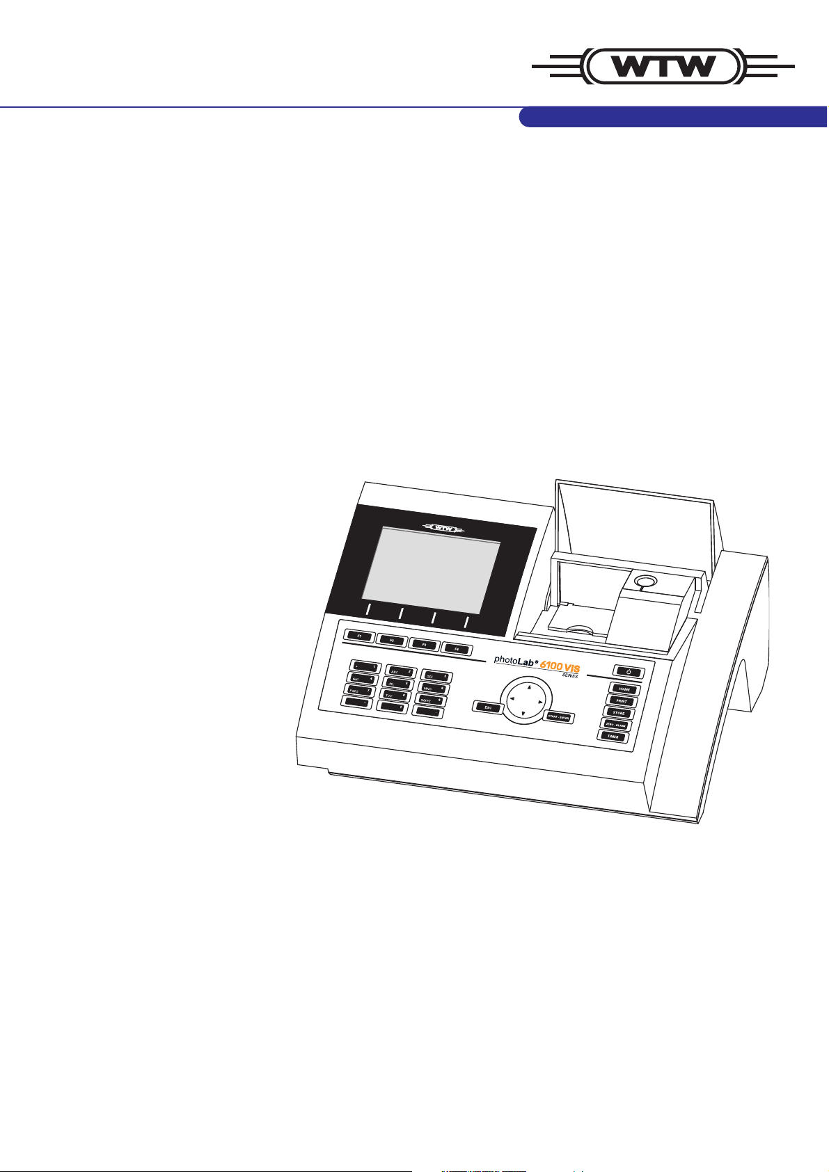
Spectrophotometer
(identical to spectroFlex 6100)
Page 2

photoLab®6100 VIS
Accuracy when going to
press
The use of advanced technology and the high quality standard of our
instruments are the result of continuous development. This may result
in differences between this operating manual and your instrument.
Also, we cannot guarantee that there are absolutely no errors in this
manual. Therefore, we are sure you will understand that we cannot
accept any legal claims resulting from the data, figures or descriptions.
Note
The latest version of the present operating manual is available on the
Internet under http://www.WTW.com.
Copyright
© Weilheim 2009, WTW GmbH
Reprinting - even as excerpts - is only allowed with the explicit written
authorization of WTW GmbH.
Printed in Germany.
ba75847e01 08/2009
Page 3

photoLab®6100 VIS Contents
photoLab®6100 VIS - Contents
1 Overview . . . . . . . . . . . . . . . . . . . . . . . . . . . . . . . . . . . . . . 7
1.1 Overview of the instrument . . . . . . . . . . . . . . . . . . . . . . . 7
1.2 Keypad . . . . . . . . . . . . . . . . . . . . . . . . . . . . . . . . . . . . . . . 8
1.3 Display . . . . . . . . . . . . . . . . . . . . . . . . . . . . . . . . . . . . . . 10
2 Safety instructions . . . . . . . . . . . . . . . . . . . . . . . . . . . . . 11
2.1 Target group and user qualification . . . . . . . . . . . . . . . . 11
2.2 Authorized use . . . . . . . . . . . . . . . . . . . . . . . . . . . . . . . . 12
2.3 General safety instructions . . . . . . . . . . . . . . . . . . . . . . . 12
2.4 Handling of hazardous substances . . . . . . . . . . . . . . . . 13
3 Commissioning . . . . . . . . . . . . . . . . . . . . . . . . . . . . . . . 15
3.1 Scope of delivery . . . . . . . . . . . . . . . . . . . . . . . . . . . . . . 15
3.2 Initial commissioning . . . . . . . . . . . . . . . . . . . . . . . . . . . 15
3.2.1 Inserting the buffer batteries . . . . . . . . . . . . . . . 16
3.2.2 Connecting the power supply . . . . . . . . . . . . . . 17
3.2.3 Switching on the photometer for the first time . . 18
3.2.4 Setting the language . . . . . . . . . . . . . . . . . . . . . 18
3.2.5 Setting the date and time . . . . . . . . . . . . . . . . . 19
3.3 Connecting optional accessories . . . . . . . . . . . . . . . . . . 20
3.3.1 Communication interfaces . . . . . . . . . . . . . . . . . 20
3.3.2 PC/printer . . . . . . . . . . . . . . . . . . . . . . . . . . . . . 21
3.3.3 USB memory device . . . . . . . . . . . . . . . . . . . . . 22
3.3.4 PC keyboard . . . . . . . . . . . . . . . . . . . . . . . . . . . 22
3.3.5 Barcode reader . . . . . . . . . . . . . . . . . . . . . . . . . 23
3.3.6 Car Adapter photoLab
®
6xxx . . . . . . . . . . . . . . 23
4 Operation . . . . . . . . . . . . . . . . . . . . . . . . . . . . . . . . . . . . 25
4.1 Switching on or off the photometer . . . . . . . . . . . . . . . . 25
4.2 General operating principles . . . . . . . . . . . . . . . . . . . . . 28
4.2.1 Navigating with function keys and menus . . . . . 28
4.2.2 Display of navigation paths in short form . . . . . 30
4.2.3 Entry of numerals, letters and characters . . . . . 31
4.2.4 Detailed operating example: Changing the
language . . . . . . . . . . . . . . . . . . . . . . . . . . . 33
4.3 Photometer settings and system administration . . . . . . 34
4.3.1 Language . . . . . . . . . . . . . . . . . . . . . . . . . . . . . 34
4.3.2 Date/Time . . . . . . . . . . . . . . . . . . . . . . . . . . . . . 35
4.3.3 Display settings . . . . . . . . . . . . . . . . . . . . . . . . . 36
ba75847e01 08/2009
3
Page 4

Contents photoLab®6100 VIS
4.4 Zero adjustment . . . . . . . . . . . . . . . . . . . . . . . . . . . . . . . 37
4.5 Measuring in Concentration mode . . . . . . . . . . . . . . . . . 41
4.5.1 Measuring cell tests with barcode . . . . . . . . . . . 41
4.5.2 Measuring reagent tests with AutoSelector . . . . 42
4.5.3 Measuring reagent-free tests and user-defined
methods . . . . . . . . . . . . . . . . . . . . . . . . . . . . . . . 44
4.5.4 Exceeding the upper or lower limits of the
measuring range . . . . . . . . . . . . . . . . . . . . . . . . 46
4.5.5 Selecting a method manually . . . . . . . . . . . . . . . 47
4.5.6 Settings for Concentration mode . . . . . . . . . . . . 48
4.5.7 Measuring diluted samples . . . . . . . . . . . . . . . . 50
4.5.8 Sample blank value . . . . . . . . . . . . . . . . . . . . . . 52
4.5.9 Reagent blank value . . . . . . . . . . . . . . . . . . . . . 54
4.5.10 Automatic Turbidity correction . . . . . . . . . . . . . . 58
4.5.11 Programming / modifying user-defined methods 58
4.5.12 The IQ LabLink procedure . . . . . . . . . . . . . . . . . 68
4.6 Measuring the Absorbance / % Transmission . . . . . . . . 69
4.6.1 General information . . . . . . . . . . . . . . . . . . . . . . 69
4.6.2 Measuring the absorbance or transmission . . . . 69
4.6.3 Measuring against the Reference absorbance . 71
4.7 Multi wavelengths methods . . . . . . . . . . . . . . . . . . . . . . 73
4.7.1 Basic information on Multi wavelengths
measurements . . . . . . . . . . . . . . . . . . . . . . . . . . 73
4.7.2 Programming / modifying Multi wavelengths
methods . . . . . . . . . . . . . . . . . . . . . . . . . . . . . . . 74
4.7.3 Selecting a Multi wavelengths method . . . . . . . 77
4.7.4 Carrying out Multi wavelengths measurements . 78
4.8 Spectrum . . . . . . . . . . . . . . . . . . . . . . . . . . . . . . . . . . . . 80
4.8.1 General information . . . . . . . . . . . . . . . . . . . . . . 80
4.8.2 Recording the Spectrum . . . . . . . . . . . . . . . . . . 81
4.8.3 Loading/editing a spectrum . . . . . . . . . . . . . . . . 84
4.8.4 Saving / exporting a spectrum . . . . . . . . . . . . . . 87
4.9 Kinetics . . . . . . . . . . . . . . . . . . . . . . . . . . . . . . . . . . . . . . 88
4.9.1 Creating/editing profiles for kinetic records . . . . 88
4.9.2 Loading a profile for kinetic recording . . . . . . . . 91
4.9.3 Recording the Kinetics . . . . . . . . . . . . . . . . . . . . 92
4.9.4 Saving / exporting a kinetic record . . . . . . . . . . . 95
4.9.5 Loading a kinetic record . . . . . . . . . . . . . . . . . . . 96
4.9.6 Editing a kinetic record . . . . . . . . . . . . . . . . . . . 97
4.10 Timer . . . . . . . . . . . . . . . . . . . . . . . . . . . . . . . . . . . . . . . . 99
4.10.1 User defined timer . . . . . . . . . . . . . . . . . . . . . . 100
4
ba75847e01 08/2009
Page 5

photoLab®6100 VIS Contents
4.10.2 Analysis timer . . . . . . . . . . . . . . . . . . . . . . . . . 100
4.11 Memory . . . . . . . . . . . . . . . . . . . . . . . . . . . . . . . . . . . . 102
4.11.1 Overview . . . . . . . . . . . . . . . . . . . . . . . . . . . . . 102
4.11.2 Instructions on using USB memory devices 104
4.11.3 Measurement datasets . . . . . . . . . . . . . . . . . . 105
4.11.4 Saving measurement datasets manually . . . . 105
4.11.5 Saving measurement datasets automatically . 106
4.11.6 Displaying measurement data memory . . . . . . 107
4.11.7 Filtering measurement datasets . . . . . . . . . . . 109
4.11.8 Inverting filters . . . . . . . . . . . . . . . . . . . . . . . . . 110
4.11.9 Erasing stored measurement datasets . . . . . . 111
4.12 Copying files . . . . . . . . . . . . . . . . . . . . . . . . . . . . . . . . . 112
4.12.1 Copying individual files to a USB memory
device . . . . . . . . . . . . . . . . . . . . . . . . . . 112
4.12.2 Copying all measurement data files to a USB
memory device . . . . . . . . . . . . . . . . . . . . . . . . 114
4.12.3 Copying files to a PC . . . . . . . . . . . . . . . . . . . . 115
4.13 Transmitting data . . . . . . . . . . . . . . . . . . . . . . . . . . . . . 116
4.13.1 Printer and terminal programs . . . . . . . . . . . . . 116
4.13.2 Settings for data transmission . . . . . . . . . . . . . 116
4.13.3 Printing measurement datasets . . . . . . . . . . . 117
4.13.4 Printing Kinetics records . . . . . . . . . . . . . . . . . 118
4.13.5 Printing spectra . . . . . . . . . . . . . . . . . . . . . . . . 119
4.14 Analytical quality assurance (AQA) . . . . . . . . . . . . . . . 120
4.14.1 General information . . . . . . . . . . . . . . . . . . . . . 120
4.14.2 Photometer monitoring (AQA1) . . . . . . . . . . . . 121
4.14.3 Total system monitoring (AQA2) . . . . . . . . . . . 126
4.14.4 AQA3/MatrixCheck . . . . . . . . . . . . . . . . . . . . . 130
4.15 User management . . . . . . . . . . . . . . . . . . . . . . . . . . . . 136
4.15.1 User levels and user rights . . . . . . . . . . . . . . . 136
4.15.2 Activating or deactivating the User
management function . . . . . . . . . . . . . . . . . . . 137
4.15.3 Creating, changing or deleting a user account 138
4.15.4 Login with active user management . . . . . . . . 141
4.15.5 Changing the password . . . . . . . . . . . . . . . . . 143
4.16 Reset . . . . . . . . . . . . . . . . . . . . . . . . . . . . . . . . . . . . . . 144
4.17 Photometer information ([Info]) . . . . . . . . . . . . . . . . . . 145
4.18 Lamp counter . . . . . . . . . . . . . . . . . . . . . . . . . . . . . . . . 145
4.19 Software and methods update . . . . . . . . . . . . . . . . . . . 146
4.19.1 Update by means of a USB memory device . . 146
4.19.2 Update by means of a PC . . . . . . . . . . . . . . . . 148
4.19.3 Software update "Chinese character set" . . . . 149
ba75847e01 08/2009
5
Page 6

Contents photoLab®6100 VIS
5 Maintenance and cleaning . . . . . . . . . . . . . . . . . . . . .151
5.1 Replacing the lamp . . . . . . . . . . . . . . . . . . . . . . . . . . . . 151
5.2 Exchanging the buffer batteries . . . . . . . . . . . . . . . . . . 153
5.3 Cleaning . . . . . . . . . . . . . . . . . . . . . . . . . . . . . . . . . . . . 154
6 What to do if ... . . . . . . . . . . . . . . . . . . . . . . . . . . . . . . . 155
6.1 Actions in the case of a broken cell . . . . . . . . . . . . . . . 155
6.2 Error causes and remedies . . . . . . . . . . . . . . . . . . . . . . 156
7 Technical data . . . . . . . . . . . . . . . . . . . . . . . . . . . . . . . 159
7.1 Measurement characteristics . . . . . . . . . . . . . . . . . . . . 159
7.2 Measured value documentation and quality assurance 162
7.3 General meter data . . . . . . . . . . . . . . . . . . . . . . . . . . . . 163
8 Accessories and options . . . . . . . . . . . . . . . . . . . . . . .165
8.1 Accessories . . . . . . . . . . . . . . . . . . . . . . . . . . . . . . . . . 165
8.2 Test equipment . . . . . . . . . . . . . . . . . . . . . . . . . . . . . . . 166
8.3 Optional equipment . . . . . . . . . . . . . . . . . . . . . . . . . . . . 166
8.4 Connection cable: . . . . . . . . . . . . . . . . . . . . . . . . . . . . . 167
Appendix . . . . . . . . . . . . . . . . . . . . . . . . . . . . . . . . . . . . 169
A.1 Menus . . . . . . . . . . . . . . . . . . . . . . . . . . . . . . . . . . . . . . 169
A.1.1 Measuring . . . . . . . . . . . . . . . . . . . . . . . . . . . . 169
A.1.2 General settings and functions . . . . . . . . . . . . 173
A.2 Glossary . . . . . . . . . . . . . . . . . . . . . . . . . . . . . . . . . . . . 177
A.3 List of trademarks . . . . . . . . . . . . . . . . . . . . . . . . . . . . . 179
3.1 Index . . . . . . . . . . . . . . . . . . . . . . . . . . . . . . . . . . . . . . . 181
6
ba75847e01 08/2009
Page 7
photoLab®6100 VIS Overview
2
1
35
6
4
7
8
9
10
1 Overview
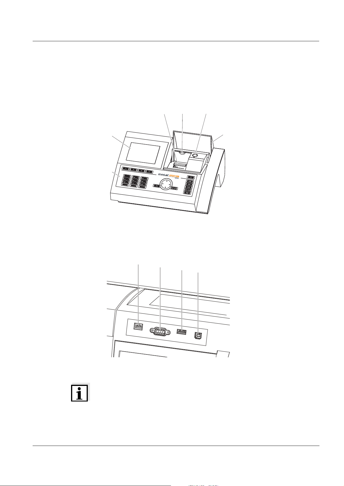
1.1 Overview of the instrument
Front of the
instrument
1Display
2 Keypad
3 Shaft for rectangular cells
4 Turn-up lid
5 Shaft for round cells
6 Cell shaft cover
Fig. 1-1 Front of the instrument with operating elements
Socket field on the
rear panel
7 Connection for power pack
8 RS232 connection
9 USB-A connection
10 USB-B connection
Fig. 1-2 Rear panel with socket field
Note
All connections comply with SELV.
ba75847e01 08/2009
7
Page 8
Overview photoLab®6100 VIS
1
2 3
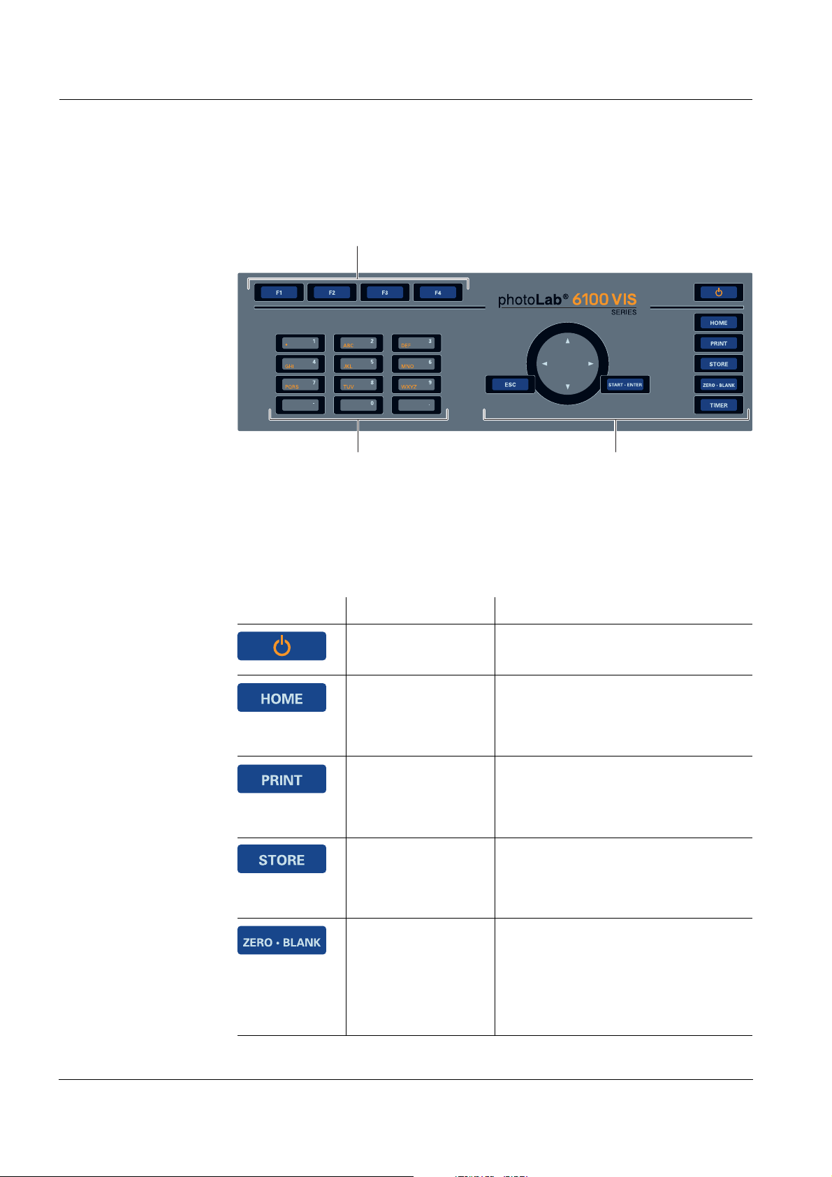
1.2 Keypad
Overview
1 Function keys F1 to F4 (function menu-depending)
2 Alphanumeric keypad
3 Keys with dedicated function
Fig. 1-3 Keypad
Key functions The keys on the right side of the keypad have the following functions:
Key Designation Functions
<ON/OFF> – Switches on and off the
photometer.
<HOME> – Switches to the main menu from
any operating situation. Actions
that are not completed are
canceled.
<PRINT> – Downloads the displayed mea-
sured value to an interface if the
Printer symbol is displayed in the
status line.
<STORE> – Saves a displayed measured
value or spectrum if the Save
symbol is displayed in the status
line.
<ZERO·BLANK> – Starts one of the following
measurements, depending on the
operating situation:
- Zero adjustment
- Blank value measurement
- Baseline measurement.
8
ba75847e01 08/2009
Page 9
photoLab®6100 VIS Overview
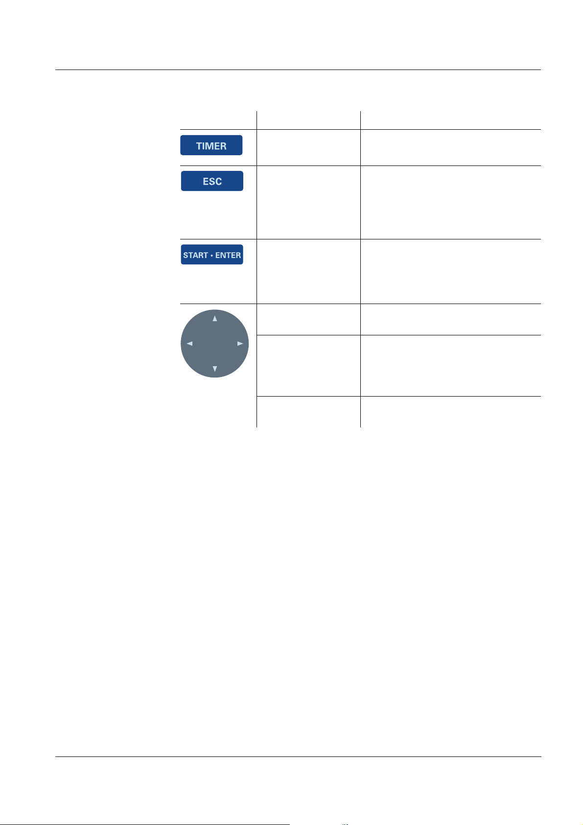
Key Designation Functions
<TIMER> – Opens the menu, Timer.
<ESC> – Cancels the running action.
Entries that have not yet been
accepted are discarded.
– Switches to the next higher menu
level.
<START·ENTER> – Starts an action (e.g.
measurement)
– Opens a selected menu
– Confirms a selection or entry
<▲>or
<▼>
– Moves the selection in menus and
lists one position up or down
<W> – Deletes the character left of the
cursor during character entries
– Moves the cursor to the left in a
spectrum or kinetic diagram
(Arrow keys)
<X> – Moves the cursor to the right in a
spectrum or kinetic diagram
Function keys The function keys F1 to F4 have different functions depending on the
operating situation. The current functions are displayed in the function key
menu at the bottom edge of the display (see section 4.2.1).
ba75847e01 08/2009
9
Page 10
Overview photoLab®6100 VIS
1
2
3
Concentration
04/16/07 9:52
1.92
mg/l
18: 14752
NH4-N
10 mm
0.05 - 3.00 mg/l
Setup
Method list
Citation form Unit
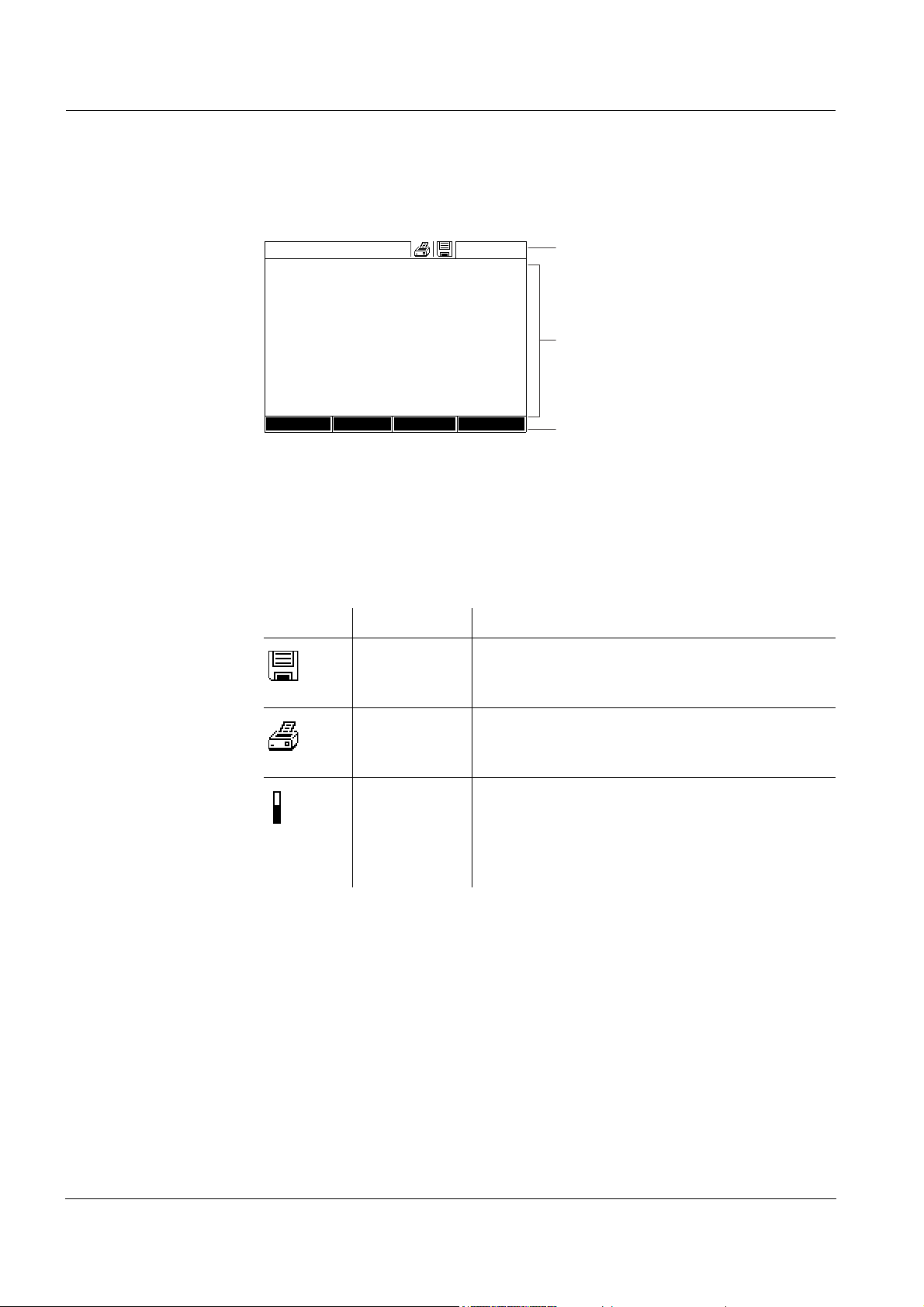
1.3 Display
Display elements
1 Status line (current state, date and time)
2 Display range for menus and measurement results
3 Function keys menu
Bild 1-4 Display
Symbols in the
status line
Symbol Designation Function
Save The <STORE> key is active.
You can store the displayed data with
<STORE> (see section 4.11).
Printer The <PRINT> key is active.
You can output to an interface the displayed
data with <PRINT> (see section 4.13).
Progress bar During the warm-up time (15 minutes) a prog-
ress bar appears on the display.
The reproducibility of measured values is limited during the warm-up time (see section
4.13).
10
ba75847e01 08/2009
Page 11
photoLab®6100 VIS Safety instructions
2 Safety instructions
This operating manual contains basic instructions that you must follow during
the commissioning, operation and maintenance of the photometer.
Consequently, all responsible personnel must read this operating manual
carefully before working with the meter. Keep this operating manual in the
vicinity of the meter.
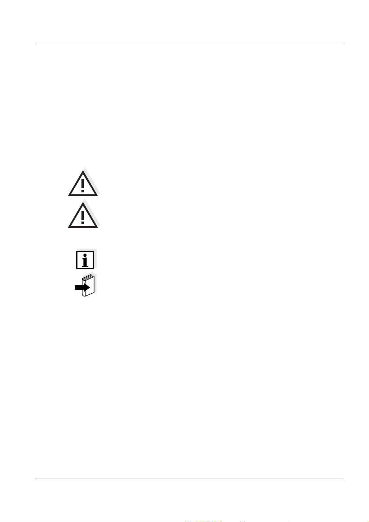
General safety
instructions
Other labels
Safety instructions in this operating manual are indicated by the warning
symbol (triangle) in the left column. The signal word (such as "caution")
indicates the danger level:
Warning
indicates instructions that must be followed precisely in order to
prevent serious dangers to personnel.
Caution
indicates instructions that must be followed precisely in order to avoid
slight injuries to personnel or damage to the instrument or the
environment.
Note
indicates notes that draw your attention to special features.
Note
indicates cross-references to other documents.
2.1 Target group and user qualification
ba75847e01 08/2009
The photometer was developed for use in the laboratory. Carrying out
photometric determinations with the aid of test sets frequently requires the
handling of hazardous substances.
We assume that the operating personnel know how to handle hazardous
substances due to their professional training and experience. The operating
personnel must particularly be able to understand and correctly implement
the safety labels and safety instructions on the packages and inserts of the
test sets.
11
Page 12

Safety instructions photoLab®6100 VIS
2.2 Authorized use
The authorized use of the photometer consists exclusively of the carrying out
of photometric measurements according to this operating manual. Follow the
technical specifications of the cells in chapter 7 T
ECHNICAL DATA. Any other
use is considered to be unauthorized.
2.3 General safety instructions
The photometer is built and inspected according to the relevant guidelines
and norms for electronic instruments (see chapter 7 T
the factory in a safe and secure technical condition.
Note
Opening the photometer or adjustment and repair work must only be
performed by specialist personnel authorized by the manufacturer.
Noncompliance invalidates any claim with regard to the warranty.
ECHNICAL DATA). It left
Function and
operational safety
The smooth functioning and operational safety of the photometer can only be
guaranteed if the generally applicable safety measures and the specific
safety instructions in this operating manual are followed during operation.
The smooth functioning and operational safety of the photometer can only be
guaranteed under the environmental conditions that are specified in chapter
7 T
ECHNICAL DATA.
If the photometer was transported from a cold environment to a warm
environment, the formation of condensate can lead to the faulty functioning
of the meter. In this event, wait until the temperature of the meter reaches
room temperature before putting the meter back into operation.
Safe operation If safe operation is no longer possible, the photometer must be taken out of
operation and secured against inadvertent operation.
Safe operation is no longer possible if the photometer:
z has been damaged in transport
z has been stored under adverse conditions for a lengthy period of time
z is visibly damaged
z no longer operates as described in this manual.
12
If you are in any doubt, contact the supplier of your photometer.
ba75847e01 08/2009
Page 13

photoLab®6100 VIS Safety instructions
2.4 Handling of hazardous substances
When developing test sets, WTW carefully sees that the tests can be carried
out as safely as possible. Some hazards by dangerous substances, however,
cannot always be avoided.
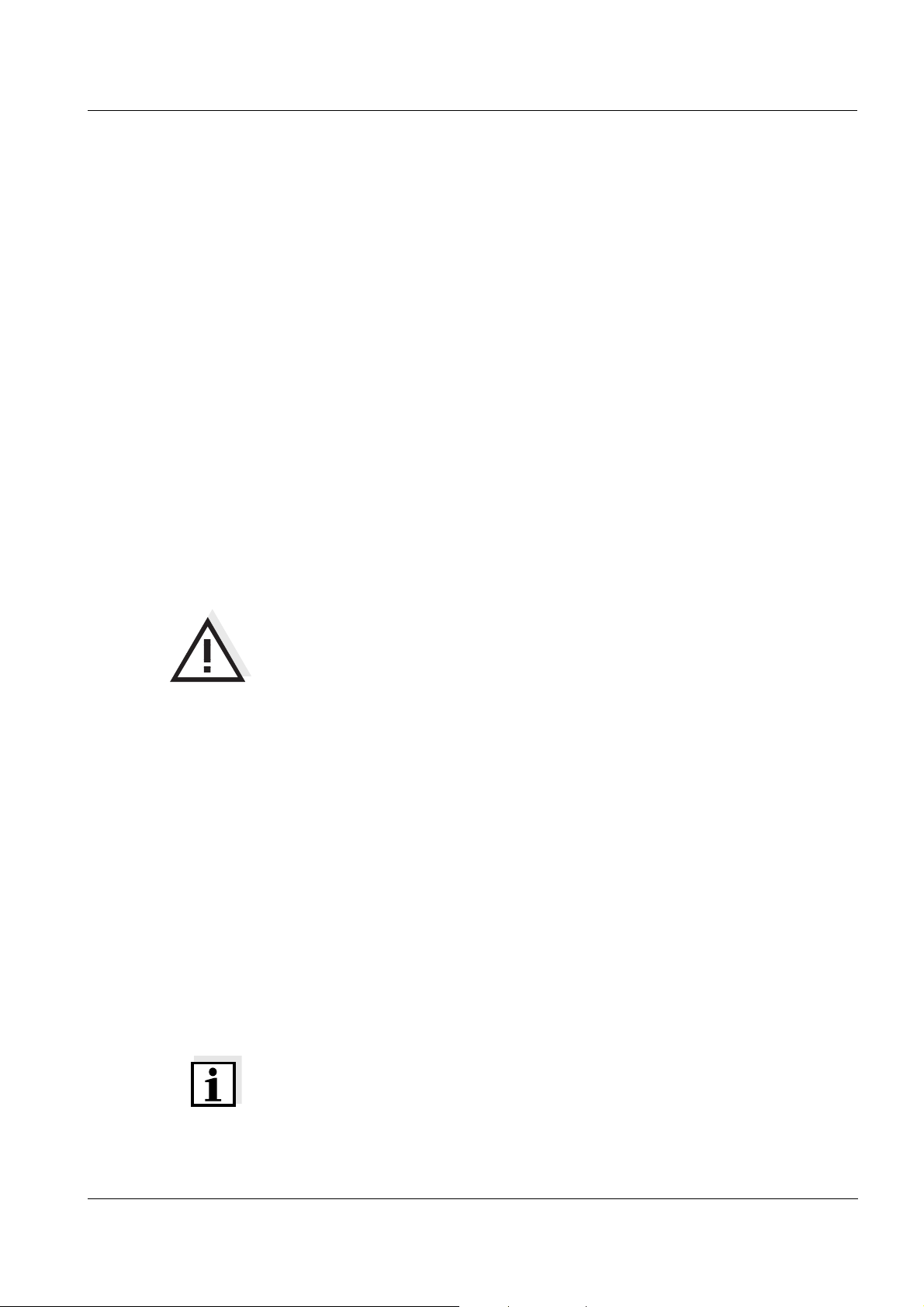
Warning
Improper handling of certain reagents can cause damage to your
health.
In any case follow the safety labels on the packing and the safety
instructions of the package insert. Protective measures specified there
have to be followed exactly.
Safety datasheets The safety datasheets of the chemicals comprise all instructions on safe
handling, occurring hazards, preventive actions and actions to take in
hazardous situations. Follow these instructions in order to work safely.
ba75847e01 08/2009
13
Page 14

Safety instructions photoLab®6100 VIS
14
ba75847e01 08/2009
Page 15
photoLab®6100 VIS Commissioning
3 Commissioning
3.1 Scope of delivery
z Spectrophotometer photoLab®6100 VIS
z Power pack connection cable
z Buffer batteries 4 x AA alkaline manganese (Mignon)
z Zero cell (16 mm, round)
z Short instructions
z CD-ROM with
– Detailed operating manual
– Analysis instructions
– SpectralTransfer software
– Software update "Chinese character set" (see section 4.19.3)
Packing This photometer is sent out in a protective transport packing.
Caution
Keep the original packing including the inner packing to protect the
instrument against hard shocks if it has to be transported.
The original packing is also required for the proper return of the
instrument if it has to be repaired.
Note that damage caused by improper transport voids all warranty
claims.
3.2 Initial commissioning
Perform the following activities:
z Insert the buffer batteries (see section 3.2.1)
z Connect the power supply (see section 3.2.2)
z Switch on the photometer (see section 3.2.3)
z Set the language (see section 3.2.4)
z Set the date and time (see section 3.2.5)
z Carry out a zero adjustment (see section 4.4)
ba75847e01 08/2009
Note
When you set the language, date and time according to the sections and of
this operating manual you will quickly become familiar with the simple
®
operation of the photoLab
operation are given in section 4.2 G
6100 VIS. More detailed instructions on
ENERAL OPERATING PRINCIPLES.
15
Page 16
Commissioning photoLab®6100 VIS
1
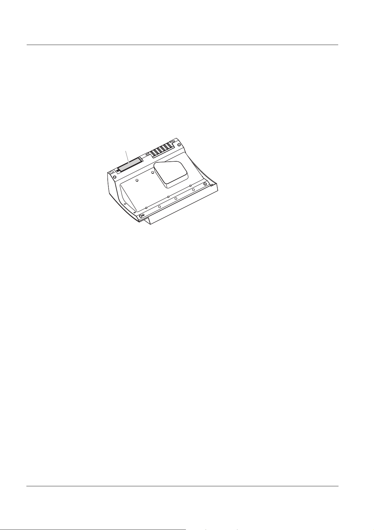
3.2.1 Inserting the buffer batteries
The buffer batteries supply the integrated clock while the photometer is
switched off. Four alkaline manganese batteries (type AA or Mignon)
separately included in the scope of delivery are used as the buffer batteries.
Insert the batteries as follows:
1 Turn the photometer upside down
and place it on a soft surface.
2 Open the lid of the battery
compartment (1).
3 Insert the four batteries in the
battery compartment. Make sure
that the poles of the batteries are
in the correct position.
The ± signs on the batteries must
correspond to the ± signs in the
battery compartment.
4 Close the lid of the battery
compartment.
Battery service life The power consumption of the clock is very low. The lifetime of high quality
batteries is at least 5 years.
16
ba75847e01 08/2009
Page 17

photoLab®6100 VIS Commissioning
1
3.2.2 Connecting the power supply
The power is supplied with the aid of the enclosed plug-in power pack. The
power pack supplies the photometer with low voltage (12 VDC).
Caution
The line voltage of the usage location must fulfill the specifications
stated on the power pack (the specifications are also given in chapter 7
T
ECHNICAL DATA). Always use the supplied 12 V original power pack
only.
Connecting the
plug-in power pack
Operation with a
mobile 12 V power
source
1 Connect the miniplug of the power
pack to the socket (1) of the
photometer.
2 Connect the power pack to an
easily accessible power socket.
The display illumination switches
itself on and then off again.
You can also operate the photoLab
®
6100 VIS on the move and independent
of the local power supply.
To do so, a 12 V power supply such as a commercial 12 V portable power
®
source or a 12 V car battery and the Car Adapter photoLab
6xxx available
as an accessory is required (see section 8.1).
ba75847e01 08/2009
More details on operation are given:
z in section 3.3.6 and
z with the Car Adapter photoLab
®
6xxx.
17
Page 18
Commissioning photoLab®6100 VIS
Language
16.04.07 9:52
Deutsch ✓
English
Français
Español
Italiano
Bulgarian/Български
Česko
Chinese/ 中文
Traditional Chinese/ 繁體中文
Greek/Ελληνικά
Indonesian/Indonesia
Language
16.04.07 9:52
Deutsch ✓
English
Français
Español
Italiano
Bulgarian/Български
Česko
Chinese/ 中文
Traditional Chinese/ 繁體中文
Greek/Ελληνικά
Indonesian/Indonesia
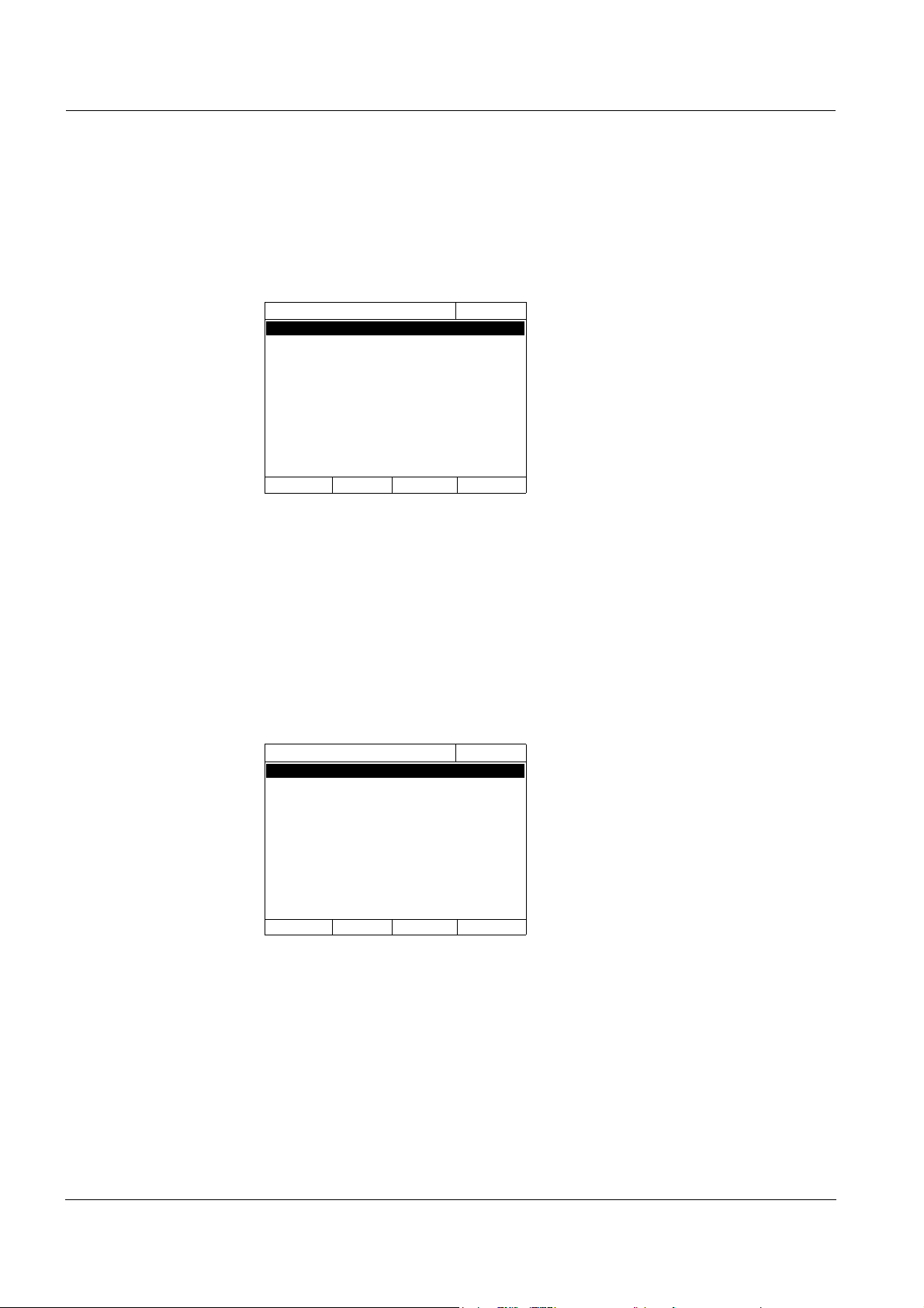
3.2.3 Switching on the photometer for the first time
During the initial commissioning, the photometer automatically guides you
through the setting of the meter language, date and time after switching on
(see following sections).
1 Press <ON/OFF>.
The photometer is switched on.
The display switches to the setting
of the language (see section
3.2.4).
After the setting of the language
the photometer carries out the
self-test.
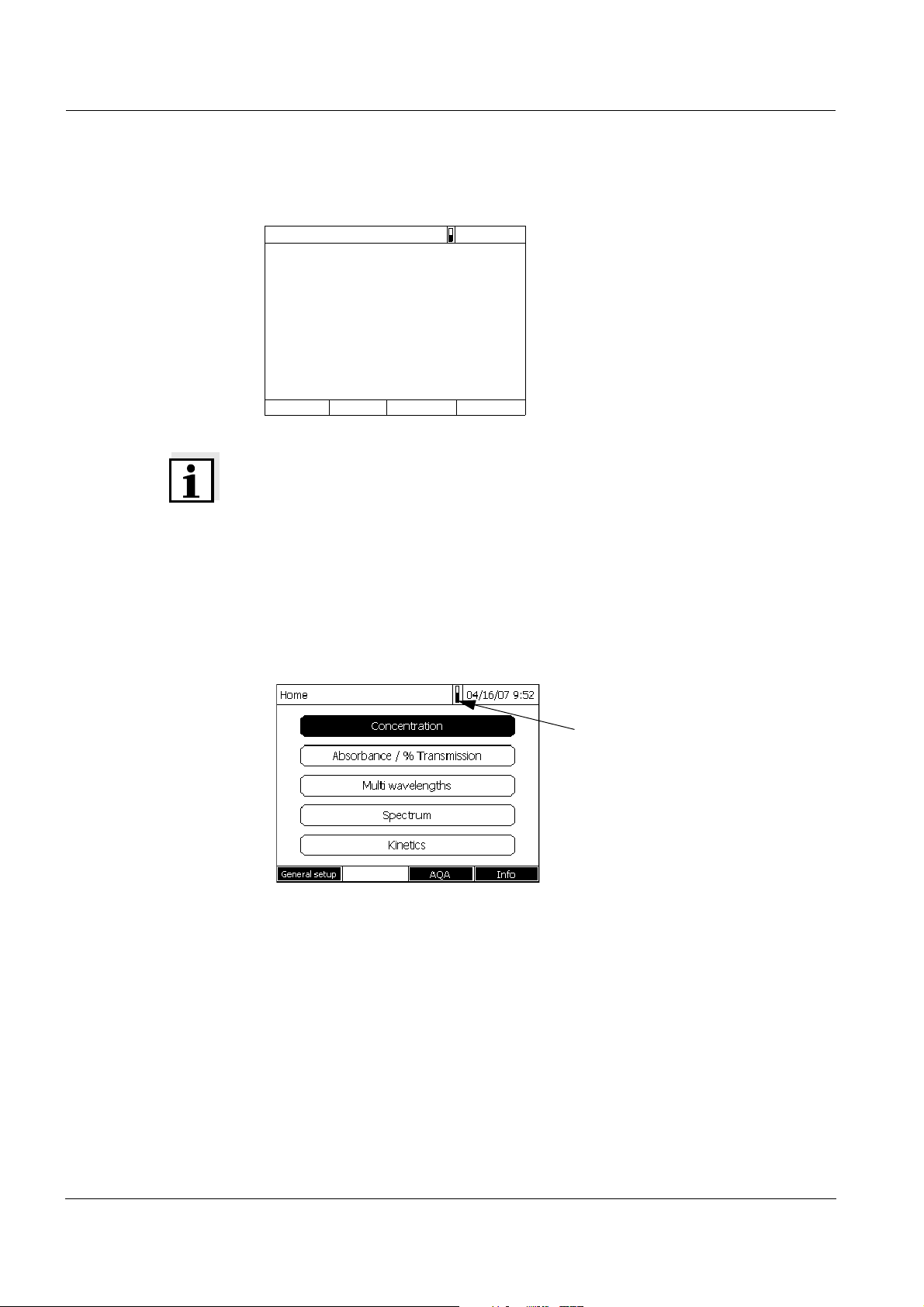
When the initial commissioning is completed, the photometer displays the
Home menu each time after it is switched on and after the self-test (see
section 4.1).
3.2.4 Setting the language
During the initial commissioning the photometer automatically guides you to
the setting of the meter language after switching on.
1 Select a language with <▲><▼>.
2 Confirm the selected language
with <START·ENTER>.
The language has been set.
The currently selected language is
marked by a tick.
The display switches to the setting
of the Date and Time (see section
3.2.5).
After the initial commissioning, you can change the language in the
General setup / Language menu at any time (see section 4.2.4).
18
ba75847e01 08/2009
Page 19
photoLab®6100 VIS Commissioning
Date/Time
16.04.07 9:52
Date 16.04.2007
Time 9:52:09
OK
Date/Time
16.04.07 9:52
Date 16.04.2007
Time 9:52:09
OK
Date
23 .10.2006
Date/Time
16.04.07 9:52
Date 16.04.2007
Time 9:52:09
OK
Time
10
:22 :09
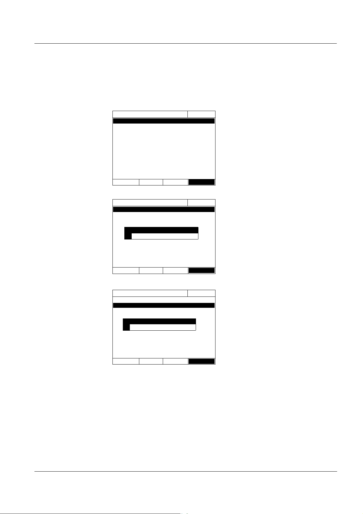
3.2.5 Setting the date and time
During the initial commissioning, the instrument automatically guides you to
the setting of the time and date after the setting of the language.
The Date/Time menu is open.
Using <▲><▼>, select a menu
item and
confirm or open it with
<START·ENTER>
.
1 Select and confirm Date.
The input field for the current date
pops up.
2 Enter the current date with <0...9>
and confirm.
The input field closes.
The date is accepted.
3 Select and confirm Time.
The input field for the current time
pops up.
4 Enter the current time with <0...9>
and confirm.
The input field closes.
The time is accepted.
After the initial commissioning, you can change the date and time in the
General setup / Date/Time menu at any time (see section 4.2.4).
ba75847e01 08/2009
19
Page 20
Commissioning photoLab®6100 VIS
USB-A
RS232
USB-B
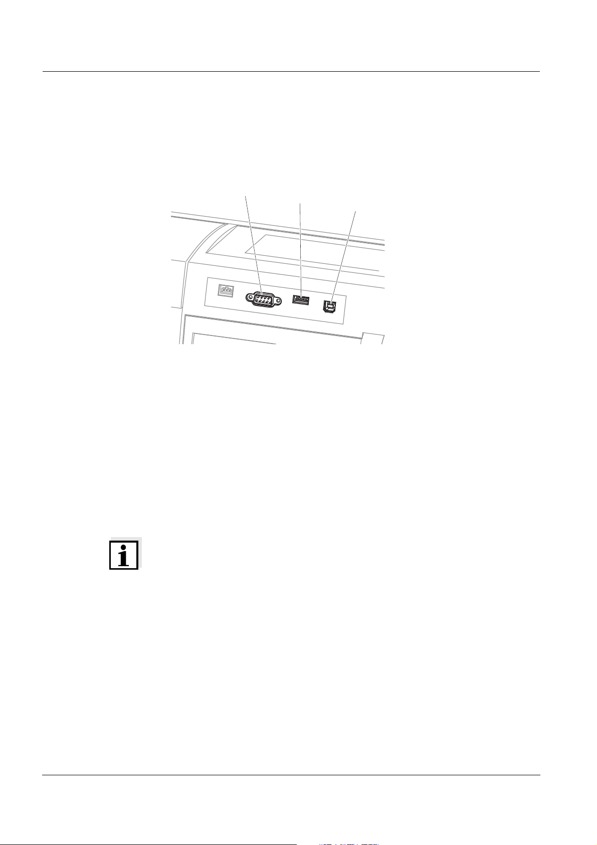
3.3 Connecting optional accessories
3.3.1 Communication interfaces
Connections
Fig. 3-1 Communication interfaces on the rear panel
You can connect the following accessories to the photometer:
z PC (see section 3.3.2)
z Printer (see section 3.3.2)
z USB storage media (see section 3.3.3)
z USB-PC keyboard (see section 3.3.4)
z Barcode reader (see section 3.3.5)
®
z Car Adapter photoLab
6xxx (see section 3.3.6)
Note
If you want to connect several USB devices such as a USB-PC keyboard and
a USB memory device to the meter, you can increase the number of USB-A
sockets by a commercially available USB-2 hub with separate power supply.
20
ba75847e01 08/2009
Page 21
photoLab®6100 VIS Commissioning
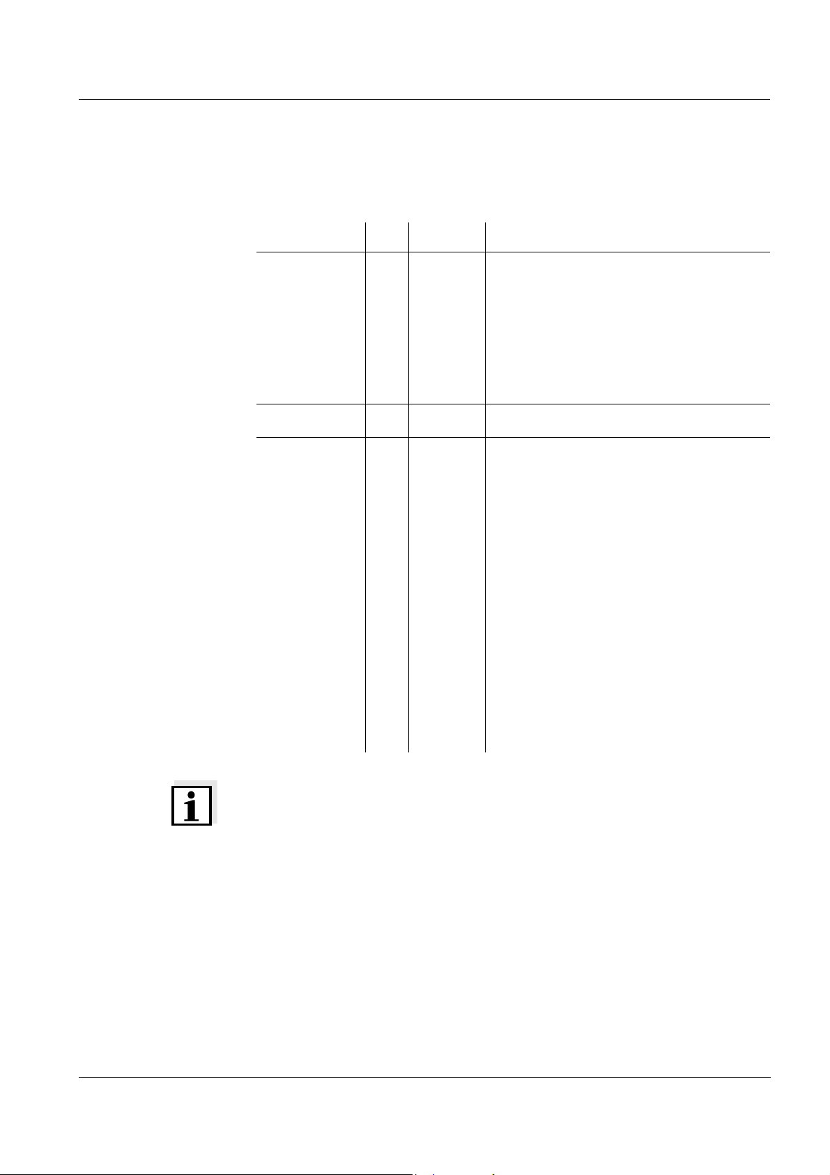
3.3.2 PC/printer
PC and printer can be connected to the photometer as follows:
Interface PC Printer Functions
RS232
USB-A
USB-B
-
The data is sent to the interface with
<PRINT>.
z If a printer is connected the data is
printed out.
z If a PC is connected, the data can be
received with a terminal program
(see section 4.13).
The data is printed out with <PRINT>.
Enables the direct connection of
photometer and PC. With this you can
transmit measurement data to the PC
(see section 4.12section 4.13) or update
the photometer software (see section
4.19.1).
The direct connection with the PC is
established with the aid of the
"SpectralTransfer" program. The
program is provided on the supplied CDROM.
More instructions on how to establish
the connection are given in the
operating manual of the
"SpectralTransfer" program (see CDROM).
ba75847e01 08/2009
Note
Suitable are all printers that can interpret the PCL-3 printer control language.
21
Page 22

Commissioning photoLab®6100 VIS
Operation at RS232 Connect the RS232 interface to the devices as follows:
z PC: with a commercially available zero modem cable
z Printer: with a commercially available RS232 printer cable
The cables are available in specialized computer shops.
Set up the following interface data at the PC/printer:
Baud rate Selectable from 1200, 2400, 4800, 9600, 19200
The baud rate must agree with the baud rate set on
the PC/printer.
Flow control
none
("handshake")
Parity none
Data bits 8
Stop bits 1
3.3.3 USB memory device
Using a USB memory device (such as a USB memory stick), you can
z Update the meter software and method data (section 4.19)
z Transmit data to the USB memory device (section 4.11)
USB memory devices are connected to the USB-A interface.
Note
Follow the instrucions on the use of USB storage media (see section 4.11.2).
22
3.3.4 PC keyboard
With the PC keyboard it is possible to enter letters, e.g. to assign names for
identification (ID).
In addition, the following keys of the PC keyboard are assigned with the
following functions of the photometer:
PC keyboard Photometer
Enter <START·ENTER>
Esc <ESC>
F1 to F4 Function keys <F1> to <F4>
ba75847e01 08/2009
Page 23
photoLab®6100 VIS Commissioning
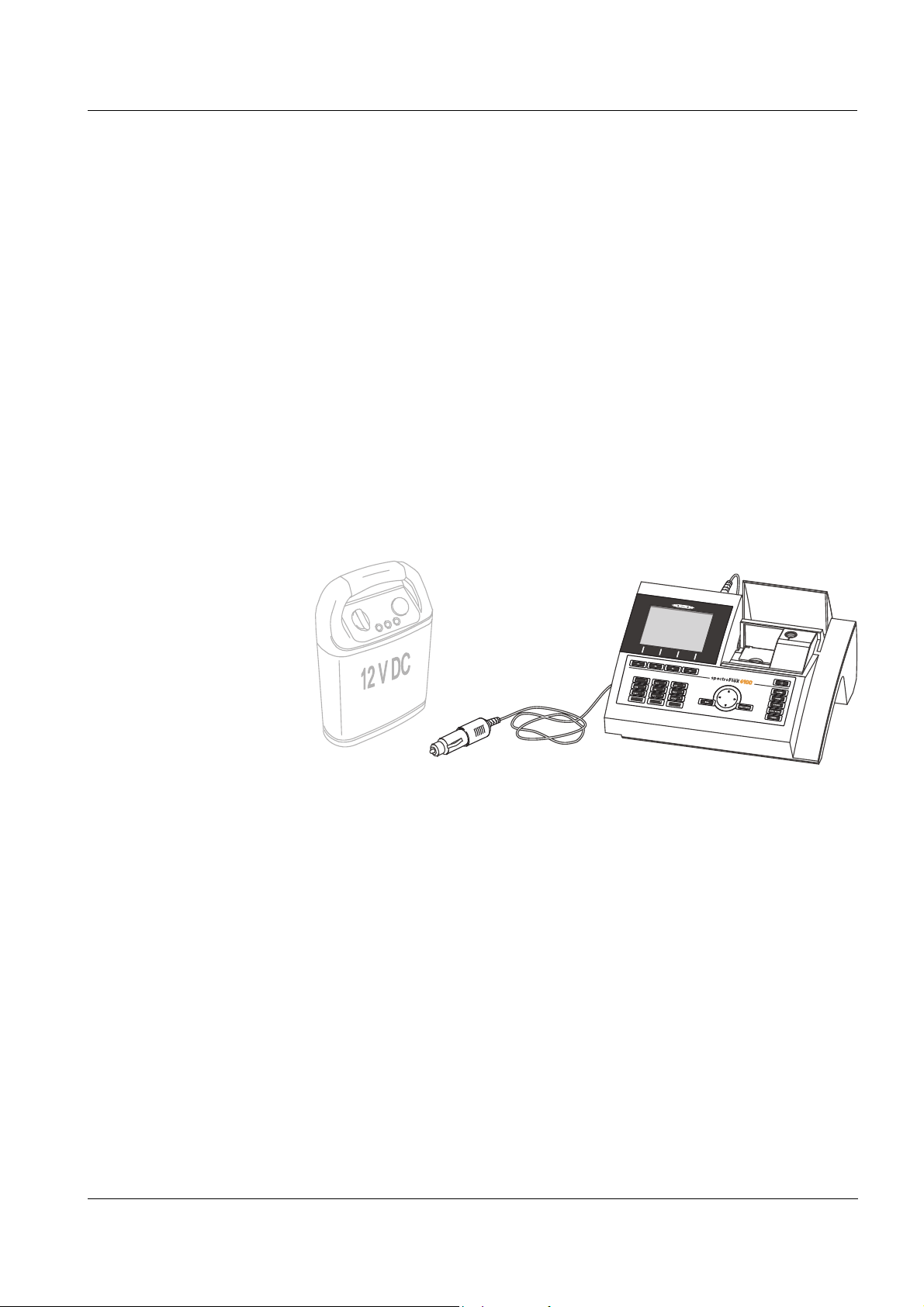
12 V power supply unit
(e.g. portable power
source or car battery )
photoLab
®
6100 VIS
Car Adapter
photoLab
®
6xx
The USB-PC keyboard is connected to the USB-A interface.
3.3.5 Barcode reader
The barcode reader enables the simplified entering of alphanumerical
character strings and can be used in all operating situations that require the
entry of text or numerals. The barcode reader is connected to the USB-A
interface.
3.3.6 Car Adapter photoLab
With the Car Adapter photoLab
®
6xxx
®
6xxx, you can operate the Pharo 6100 and
Pharo 6600 spectrophotometers on the move and independent of the local
power supply.
To do so, a 12 V power supply such as a commercial 12 V portable power
source or a 12 V car battery is required.
Safety instructions For operation with an external battery, follow the safety instructions of the
battery.
Make sure the power source is suitable for operation of the
spectrophotometer (see technical data of the power source and technical
data of the spectrophotometer).
Operating time
with a battery
The maximum operating time depends on various factors:
z Battery (e.g. nominal capacity, condition, age)
z Operating mode of the photometer (e.g. frequency of measurements)
Example:
z Photometer (instrument type)
Operating time with a 12 V / 19 Ah type battery in optimum condition: approx.
6.5 h
ba75847e01 08/2009
23
Page 24
Commissioning photoLab®6100 VIS
Note
The spectrophotometer consumes electricity even while it is in standby
mode.
We recommend to disconnect the photoLab
®
6100 VIS if you do not use the
spectrophotometer during battery operation.
Technical data
Car Adapter
photoLab
®
6xxx
Cable length 2 m
Max. voltage 12 V
Max. current 8 A
24
ba75847e01 08/2009
Page 25
photoLab®6100 VIS Operation
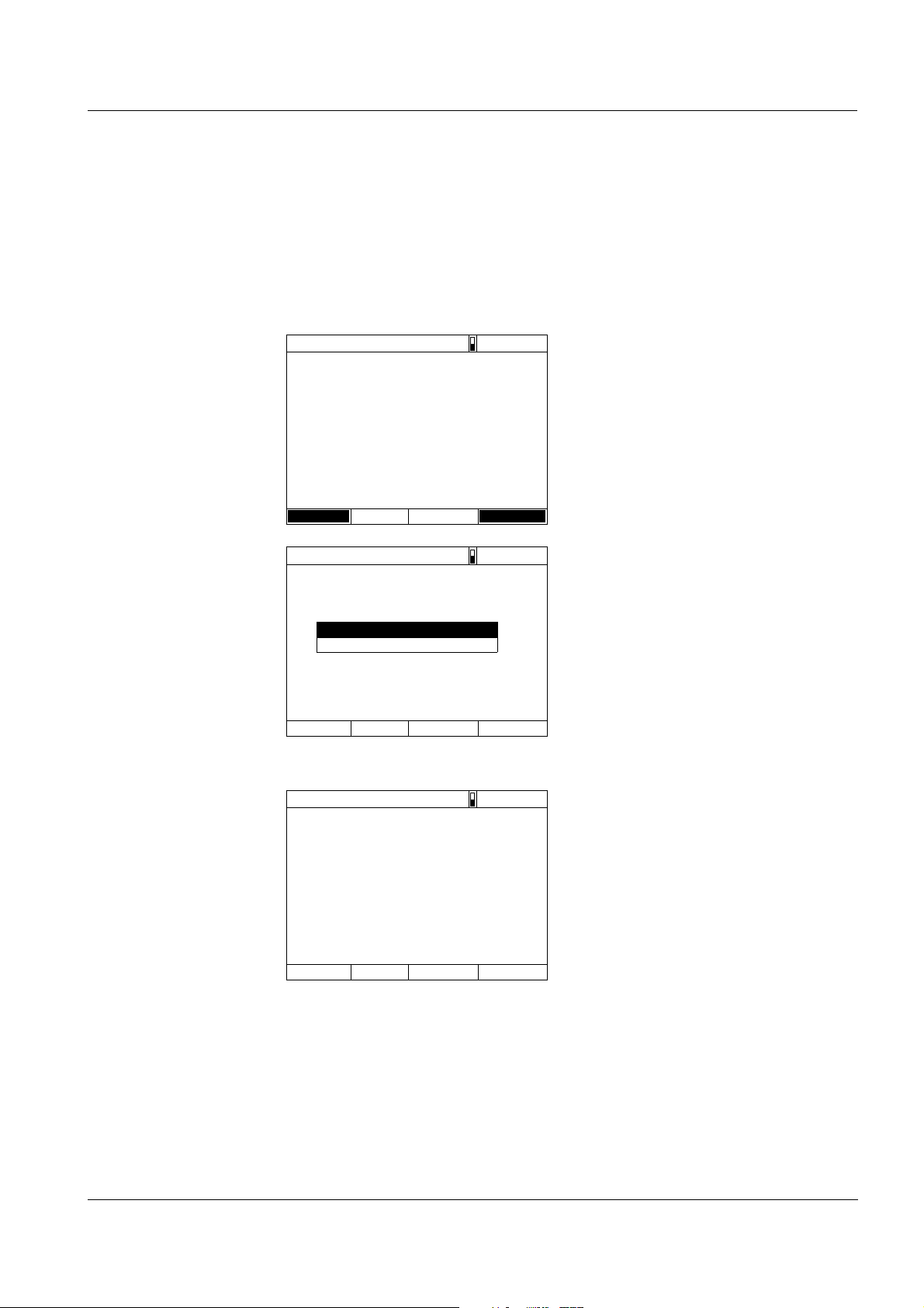
Self test
04/16/07 9:52
Please make sure no cell is inserted and the cover is closed.
Then press <START/ENTER>
Setup Info
Login
04/16/07 9:52
Enter user name
Administrator
Self test
04/16/07 9:52
Please make sure no cell is inserted and the cover is closed.
Then press <START/ENTER>
4 Operation
4.1 Switching on or off the photometer
Switching on
1 Switch the photometer on with
<ON/OFF>.
The display shows
– the Self test dialog (if the user
management is not active).
or
– the Login dialog
(if the user management is
active).
With activated user management:
2 Login
Enter user name and password or
register as a guest (see section
4.15.4).
Then the photometer displays the
Self test dialog.
Starting the
Self test
ba75847e01 08/2009
3 Remove all cells and close the cell
shaft cover.
4 Start the self-test with
<START·ENTER>.
The photometer carries out the
self-test.
25
Page 26
Operation photoLab®6100 VIS
Self test
04/16/07 9:52
Keep cover closed
System test
Filter test
Lamp test
Wavelength calibra tion
Progress bar during warm-up
time
Self test During the self-test, all cells must be removed and the cell shaft cover closed.
The self-test includes:
– the test of the memory,
processor,
internal interfaces,
filter and lamp
– a calibration for each
wavelength
After the self-test is completed,
the main menu is displayed.
Note
The result of the self-test can be viewed and printed with the [Info] function
key (see section 4.17).
Warm-up time After switching on the photometer requires a warm-up time of 15 minutes.
Reproducibility of measurement data is restricted during the warm-up time.
Therefore, do not measure during the warm-up time.
During the warm-up time, a progress bar appears on the display next to the
date. The progress bar disappears as soon as the warm-up time is over.
26
ba75847e01 08/2009
Page 27

photoLab®6100 VIS Operation
AutoCheck With the AutoCheck function the photometer checks and calibrates the
optical measuring unit. The AutoCheck is automatically carried out if
measurement settings were changed since the last measurement, e.g.:
z if a different wavelength was selected or
z if a different method was selected.
If necessary, the photometer asks you to remove the cell from the cell shaft.
With unchanged measurement settings, the AutoCheck is carried out in the
background at regular intervals of 5 minutes. The AutoCheck can only be
carried out in the background if the cell shaft is empty. If a cell is in the cell
shaft the AutoCheck is carried out only after the cell was removed.
Note
Remove the cell from the cell shaft after every measurement. Thus the
photometer can carry out the regular AutoCheck.
Cells must be completely removed from the cell shaft.
Cells that are removed only half disturb the AutoCheck measurement and, as
a consequence, falsify measured values until the next AutoCheck is carried
out.
Plastic cells that are not recognized by the automatic cell recognition also disturb the AutoCheck.
Note
During a running kinetic measurement the photometer cannot carry out any
AutoCheck. That is why in this case a warm-up time of two hours is required.
After this time the signal is stable enough so that the measurement accuracy
is secured over a longer period of time.
Display illumination The photometer automatically switches off the display illumination if no key
has been pressed for 5 minutes. The illumination is switched on again with
the next keystroke. The function of the key becomes active only with the
following keystroke.
Switching off To switch the photometer off, keep the <ON/OFF> key depressed until the
photometer is switched off.
ba75847e01 08/2009
27
Page 28
Operation photoLab®6100 VIS
Press twice<>q
Moves the selection down
by 2 positions
Current selection
in reverse video
Confirm selection
with <START ENTER>
Further navigation
andwith <><>pq
<START ENTER>
Further navigation
with function keys
(here: F1 and F2)
Press the F1
Funktion key
("Settings")
Opens the
"Settings"
submenu
Updated function
key menu in the
multi wavelengths
mode
Function key
menu
Main menu
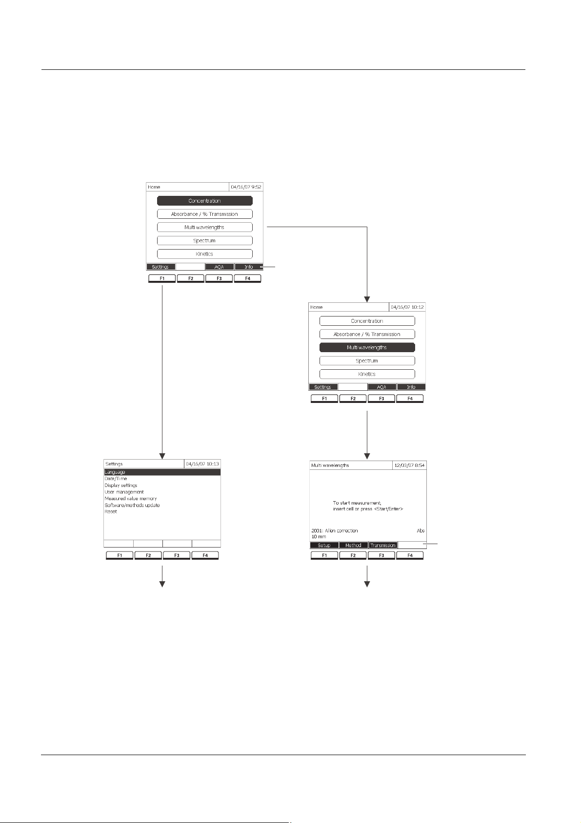
4.2 General operating principles
4.2.1 Navigating with function keys and menus
Bild 4-1 Example of navigation with function keys (left) and "classical" menu navigation
(right)
28
ba75847e01 08/2009
Page 29

photoLab®6100 VIS Operation
Use of the function
keys
Navigation with
arrow keys
(<▲><▼>) and
<START·ENTER>
The function keys F1 to F4 are below the display. Their functions change
depending on the operating situation and mode. The current functions are
displayed in the function key menu at the bottom edge of the display.
Apart from navigation, the function keys are also used for other operations:
z Opening a selection list or input field
z Executing a command (directly or with intermediate query)
z Switch over between two display options,
such as absorbance
Q transmission
These operating elements are used to select an item from a menu or list. The
current selection is displayed in reverse video. Pressing of
<START·ENTER> confirms the selection.
Apart from navigation, the <START·ENTER> key is also used for other
operations:
z Opening a selection list or input field
z Confirming a selection
z Confirming entries of text and numerals
z Executing a command (directly or with intermediate query)
z Activating an item in a selection list (✓ = active)
ba75847e01 08/2009
29
Page 30

Operation photoLab®6100 VIS
<HOME>
[General setup]
– Language
Bold letters and angle brackets
indicate a key on the photometer
(except function keys).
→ Press the "Home" key.
The main menu is called up.
Square brackets indicate a
function key F1 to F4. The text
between the brackets
corresponds to the assignment
according to the function key
menu on the bottom edge of the
display.
→ Press the function key with the
assignment "Settings"
Text without brackets stands for a
menu item indicated on the
display (list item).
→ Select the menu item with the
arrow keys <S><T>. The
current selection is displayed
in reverse video.
→ Then press
<START·ENTER>.
4.2.2 Display of navigation paths in short form
In this operating manual, the introductory navigation steps leading to
individual menus or dialogs are clearly shown in a gray box. The box
indicates a section of the menu tree.
Starting point of the description is always the main menu, which can be
reached with the <HOME> key from any operating situation. From there
navigation takes place downward.
Operating example:
Navigation to the
setting menu for the
The following example shows the elements of the menu tree with the relevant
operating steps:
language
30
Further navigation options:
z The <ESC> key moves you one level up in the menu tree.
z The <HOME> key directly calls up the main menu.
Note
If you are "lost" in a menu, press <HOME> and restart navigating from the
main menu.
ba75847e01 08/2009
Page 31

photoLab®6100 VIS Operation
Note
The complete menu tree is given in the appendix of this operating manual.
4.2.3 Entry of numerals, letters and characters
Numerals, letters, punctuation marks and special characters are entered with
the alphanumeric keypad of the meter or using an external keyboard.
Entries are required in operating situations such as the following:
z Entering the date and time
z Entering an ID e.g. when storing measurement data
z Selecting a method with the [Search] function
z Programming user-defined methods
z Entering user name and password
z Administrating users
Character set The following characters are available:
z Numerals 0 ... 9
z Letters A ... Z and a ... z
z Punctuation marks. -
z Special characters ° / + ² ³ # %
Operating principle Entering characters is always possible if there is an input field on the display.
The numerals and characters (expect for the small letters) assigned to the
keys of the alphanumeric keypad are printed on the keys. Example: With the
<7/PQRS> key you can enter the following characters: 7, P, Q, R, S, p, q, r, s.
Select the required character by pressing the key several times (similar to a
mobile phone). When pressing a key that is assigned to several characters
once, the respective numeral appears first. To enter a numeral, one
keypressing is always sufficient.
When pressing the key for the first time a line pops up that displays all
characters possible with this key. The currently selected character is
highlighted.
A character is taken over in the input field if
ba75847e01 08/2009
z the character is highlighted for more than one second,
z the character is confirmed with <START·ENTER>,
z another alphanumeric key is pressed.
31
Page 32

Operation photoLab®6100 VIS
Enter ID
8
8 T U V t u v
Enter ID
T
8
T
T U V t u v
Enter ID
Tes t_
Note
During mere number entries (such as entering a wavelength), the keys of the
alphanumeric keypad are assigned to the respective numeral only. Each
keypressing directly enters the numeral (like a pocket calculator).
Special characters Special characters are entered with the <1/*> key.
Operating example:
Entering the ID
Correcting incorrect
entries
The Enter ID input field appears if you press the <STORE> key while the
storing symbol is visible. In the following example a measurement dataset
with the ID "Test" is stored.
1 Press <8/TUV> several times until
"T" appears in the input line.
Below the input field, a selection
line pops up with all characters
that are available for this key, e.g.
8 T U V t u v.
The currently selected character is
highlighted.
After approx. one second the
character is taken over and the
selection line closed.
2 Complete the ID with <A...9> and
confirm.
Using <W>, erase all characters until you have reached the incorrect digit and
repeat the entry from there.
32
ba75847e01 08/2009
Page 33

photoLab®6100 VIS Operation
General setup
04/16/07 9:52
Language
Date/Time
Display settings
User managementg
Measured value memory
Software/methods up date
Reset
Data transfer/Printer
Save all data on USB memory
Language
16.04.07 9:52
Deutsch ✓
English
Français
Español
Italiano
Bulgarian/Български
Česko
Chinese/ 中文
Traditional Chinese/ 繁體中文
Greek/Ελληνικά
Indonesian/Indonesia
Deutsch ✓
4.2.4 Detailed operating example: Changing the language
1 Call up the main menu with the
<HOME> key.
2 Open the General setup menu
with the F1 function key [Setup].
3 Using <S><T>
, select the
Language menu item and open
with <START·ENTER>.
The Language menu shows a list
with the available languages. The
currently active language is
marked by a tick.
4 Select the required language from
the list with <S><T> and confirm
with <START·ENTER>.
The selected language is taken
over immediately. The photometer
moves up one menu level.
ba75847e01 08/2009
33
Page 34

Operation photoLab®6100 VIS
4.3 Photometer settings and system administration
The general photometer settings are done in the <HOME> -> General setup
menu. The general photometer settings comprise:
z Language (see section 4.3.2)
z Date/time (see section 4.3.2 and section 4.2.4)
z Display characteristics (see section 4.3.3)
z User management (see section 4.15)
z Administration of the measurement data memory (see section 4.11)
z Software and method update (see section 4.19)
z Reset of the settings to default values (see section 4.16)
z Settings for data transmission (see section 4.13.2)
4.3.1 Language
The complete list of the available instrument languages is given in the
Sprache/LanguageLanguage menu of the photometer and in chapter 7 T
NICAL DATA.
ECH-
Note
You can select the "Simplified Chinese/ 中文 " or "Traditional Chinese/ 繁體中
文 " language only if the Chinese character set has been previously installed
(see section 4.19.3).
Note
How to set the language is described in detail in the operating example in
section 4.2.4.
34
ba75847e01 08/2009
Page 35

photoLab®6100 VIS Operation
<HOME>
[General setup]
– Date/Time
Date/Time
04/16/07 9:52
Date 16.04.2007
Time 9:52:09
OK
Date
23 .10.2006
Date/Time
04/16/07 9:52
Date 16.04.2007
Time 9:52:09
OK
Time
10
:22 :09
4.3.2 Date/Time
The date format is set automatically with the language setting.
According to the locally usual version, the date format is displayed in the
order, Day.Month.Year (DD.MM.YY) or Month/Day/Year (MM/DD/YY or
MM.DD.YY).
The Date/Time menu is open.
1 Select and confirm Date.
The input field for the current date
pops up.
2 Enter the current date with <0...9>
and confirm.
The input field closes.
The date is accepted.
3 Select and confirm Time.
The input field for the current time
pops up.
4 Enter the current time with <0...9>
and confirm.
The input field closes.
The time is accepted.
ba75847e01 08/2009
35
Page 36

Operation photoLab®6100 VIS
<HOME>
[General setup]
– Display settings
Display settings
04/16/07 9:52
Contrast 50 %
4.3.3 Display settings
Here you can adjust the display contrast to the lighting conditions.
1 Select and confirm Contrast.
A slide control for the display
contrast appears.
2 Using <W><X>, set the display
contrast and confirm.
36
ba75847e01 08/2009
Page 37

photoLab®6100 VIS Operation
4.4 Zero adjustment
A valid zero adjustment is required for the calculation of measured values in
the modes, Concentration, Absorbance / % Transmission, Multi wavelengths
and Kinetics. With a zero adjustment, the absorbance of a cell filled with
distilled water ("zero cell") is measured and stored.
Zero adjustment for
absorbance
measurements
Factory zero
adjustment for
concentration
measurements
Notes on zero
adjustment
The zero adjustment has to be carried out separately for each cell type and
each used wavelength. If necessary, the photometer reminds you that a zero
adjustment is due.
For all measurements with WTW test sets (Concentration mode), a factory
zero adjustment is available in the delivery condition. We recommend
replacing it with a zero adjustment of your own.
Note
The cells must be absolutely clean and free of scratches.
Always use a cell of the same type for zero adjustment and measurement of
the sample.
Zero adjustment with round cells:
z Only use clean, scratch-free round cells with distilled water. The minimum
filling level is 20 mm. A ready zero cell is included in the scope of delivery
of the photometer and PhotoCheck (see chapter 8 A
OPTIONS).
CCESSORIES AND
z A ready zero cell can, in principle, be used any number of times. We
recommend, however, to regularly check the zero cell for visible
contamination and scratches and refill or exchange it if necessary (at least
every 24 months).
ba75847e01 08/2009
Zero adjustment with rectangular cells:
z For rectangular cells, the zero adjustment must be carried out with the
same cell type (manufacturer and glass type [e.g. optical glass, quartz
glass]) that is used for measurement. This is important because cells of
different manufacturers have different absorption behavior. When
changing the cell type repeat the zero adjustment with the new type.
z Prior to zero adjustment, clean the rectangular cell and fill it with distilled
water. The minimum filling level is 20 mm.
z Rectangular cells always have to be inserted in the cell shaft with the
same orientation for measurement and zero adjustment (e.g. cell printing
on the left side ).
37
Page 38

Operation photoLab®6100 VIS
Concentration
04/16/07 9:52
3: A6/25
NH4-N
16 mm
0.20 - 8.00 mg/l
Setup
Method list
Citation form Unit
Adjust
Blank value
Zero adj ust men t
Zero adju stm ent
04/16/07 9:52
Please insert zero cell (distilled water)
or press <Start/Enter>
Zero cell
(H O dist.)
2
inner
turn-up lid
Note
Ordering information is given in chapter 8 A
cells listed in the chapter 8 A
CCESSORIES AND OPTIONS are especially adapted
CCESSORIES AND OPTIONS. The
to the WTW test set program. General requirements of the cells are given in
chapter 7 T
ECHNICAL DATA. Note that the spectral transparency of the cell
must be suitable for the intended application (example, quartz cell for UV
range).
Carrying out a zero
adjustment
The zero adjustment takes place similarly in the Concentration, Absorbance
/ % Transmission, Multi wavelengths and Kinetics modes.
1 In the respective mode, press the
<ZERO·BLANK> key.
2 In Concentration mode only:
Select and confirm Zero
adjustment.
The zero adjustment window pops
up.
38
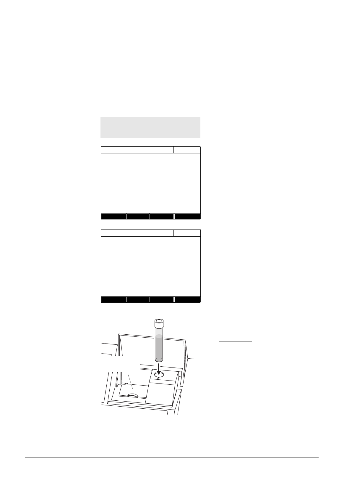
3 Close the inner turn-up lid.
4 Depending on the cell type, insert
the zero cell as follows:
Round cell:
Insert the round cell in the round
cell shaft so it touches the bottom.
If the inner turn-up lid is opened
too wide, a message prompts you
to close the inner turn-up lid.
ba75847e01 08/2009
Page 39

photoLab®6100 VIS Operation
Zero cell
(H O dist.)
2
Zero adju stm ent
04/16/07 9:52
Zero adjustment successful
10 mm
OK
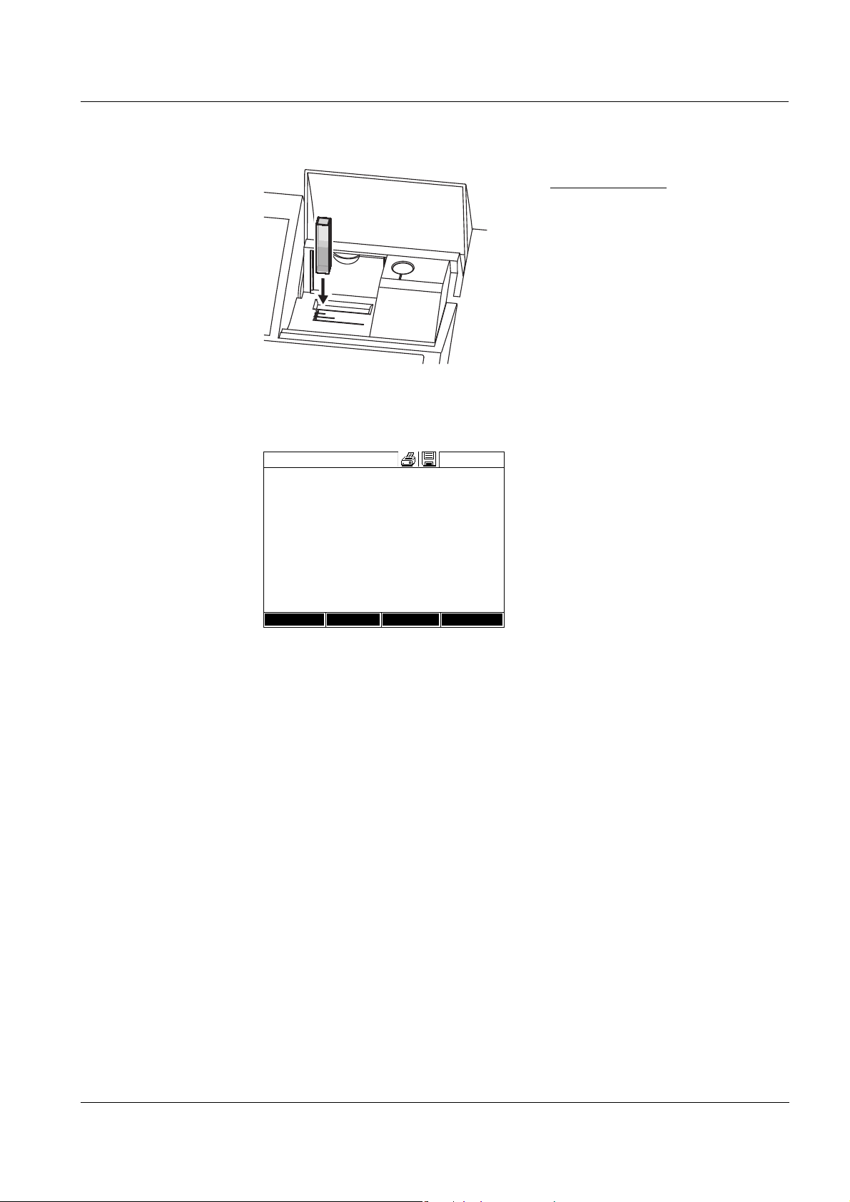
Rectangular cell:
Open the inner turn-up lid.
Insert the rectangular cell
vertically so it touches the bottom
and left edge of the cell shaft. The
opaque sides of the rectangular
cell must point to the front and
back.
The photometer has an external
light recognition. If there is too
much external light, a message
prompts you to close the cell shaft
cover.
The photometer automatically
starts the zero adjustment and
subsequently stores the value.
5 After a successful zero adjustment
switch to measurement with [OK].
ba75847e01 08/2009
39
Page 40

Operation photoLab®6100 VIS
Validity of the zero
adjustment
The data of the zero adjustment is stored in the photometer separately for
each cell type. As long as the data is valid, it is automatically used again after
a temporary change to a different cell type. The validity depends on the
respective mode:
Mode Validity of the zero adjustment
Concentration (permanently
z Till the next zero adjustment
programmed methods)
Absorbance / % Transmission z Till the next zero adjustment with the
same wavelength *
Concentration (user-defined
methods) and
z Till the next zero adjustment for the same
method *
Multi wavelengths
Kinetics z Till another kinetic profile is loaded
z Till the Kinetics mode is exited or the
photometer is switched off
* After the wavelength or method respectively was temporarily exited the photometer
displays that a zero adjustment is available and the time it was carried out. You can then
decide whether to use this zero adjustment or carry out a new zero adjustment.
When to repeat the
zero adjustment?
We recommend to repeat the zero adjustment in the following cases:
z If the photometer was subject to mechanical stress such as strong shock
or transport
z If the ambient temperature changed by more than 5 °C since the last zero
adjustment
z After the lamp was replaced
z At least once per week
z If a new cell type (different manufacturer, different glass type is used)
z Basically each time you want to measure with the highest possible
accuracy.
40
ba75847e01 08/2009
Page 41

photoLab®6100 VIS Operation
<HOME>
Concentration
Concentration
04/16/07 9:52
Please select method for measuring
or insert a barcoded cell
or insert AutoSelector.
Setup
Method list La st method New Method
Line mark
Barcode
Concentration
04/16/07 9:52
49
mg/l
18: C3/25
COD
16 mm
10 - 150 mg/l
Setup
Method list
Citation form Unit
4.5 Measuring in Concentration mode
4.5.1 Measuring cell tests with barcode
Inserting a cell with barcode starts
a measurement.
1 Open the cell shaft cover.
2 Close the inner turn-up lid.
If the inner turn-up lid is opened
too wide, a message prompts you
to close the inner turn-up lid.
3 Insert the barcoded round cell in
the round cell shaft so it touches
the bottom. When doing so, align
the line mark with the notch at the
front of the round cell shaft.
The photometer selects the
method based on the bar code
and automatically starts
measurement.
4 Further options:
– Select a different citation form
with [Citation form],
(e.g. NH
<–> NH4-N).
4
– Select a different measuring
unit with [Unit],
(e.g. mg/l <–> mmol/l).
– Make further settings such as
dilution or blank value
measurements with [Setup]
(see section 4.5.6).
ba75847e01 08/2009
Display if the value is not within the measuring range (see section 4.5.4).
41
Page 42

Operation photoLab®6100 VIS
<HOME>
Concentration
Concentration
04/16/07 9:52
Please select method for measuring
or insert a barcoded cell
or insert AutoSelector.
Setup
Method list La st method New Method
Concentration
04/16/07 9:52
To start measurement,
insert cell or press <Start/Enter>
38: 14761
Fe
10 mm
0.05 - 5.00 mg/l
Setup
Method list
Citation form Unit
Line mark
Barcode
inner
turn-up lid
4.5.2 Measuring reagent tests with AutoSelector
The method is selected by
inserting the AutoSelector.
The photometer is ready to
measure.
1 Open the cell shaft cover.
2 Insert the AutoSelector in the
round cell shaft so it touches the
bottom. When doing so, align the
line mark with the notch at the
front of the round cell shaft.
– The photometer selects the
correct method with the aid of
the barcode.
42
ba75847e01 08/2009
Page 43

photoLab®6100 VIS Operation
Concentration
04/16/07 9:52
1.92
mg/l
18: 14752
NH4-N
10 mm
0.05 - 3.00 mg/l
Setup
Method list
Citation form Unit
3 Open the inner turn-up lid.
4 Insert the rectangular cell
vertically so it touches the bottom
and left edge of the cell shaft. The
opaque sides of the rectangular
cell must point to the front and
back.
The correct measuring range is
automatically selected when the
rectangular cell (1, 2, 5 cm) is
inserted.
The photometer has an external
light recognition. If there is too
much external light, a message
prompts you to close the cell shaft
cover.
The photometer starts measuring
automatically.
5 Further options:
– Select a different citation form
with [Citation form],
(e.g. NH
<–> NH4-N).
4
– Select a different measuring
unit with [Unit],
(e.g. mg/l <–> mmol/l).
– Make further settings such as
dilution or blank value
measurements with [Setup]
(see section 4.5.6).
Display if the measured value is not within the measuring range (see section
4.5.4).
ba75847e01 08/2009
43
Page 44
Operation photoLab®6100 VIS
<HOME>
Concentration
Concentration
04/16/07 9:52
Please select method for measuring
or insert a barcoded cell
or insert AutoSelector.
Setup
Method list La st method New Method
Concentration
04/16/07 9:52
To start measurement,
insert cell or press <Start/Enter>
3: A6/25
NH4-N
16 mm
0.20 - 8.00 mg/l
Setup
Method list
Citation form Unit
inner
turn-up lid
4.5.3 Measuring reagent-free tests and user-defined methods
User-defined methods and reagent-free methods normally do not have a
barcode and therefore, no automatic method recognition. In such a case,
select the method manually:
1 Select the method manually
(see section 4.5.5).
The photometer is ready to
measure.
2 Depending on the type, insert the
cell as follows:
Round cell:
Close the inner turn-up lid.
Insert the round cell in the round
cell shaft so it touches the bottom.
If the turn-up lid is opened too
wide, a message prompts you to
close the inner turn-up lid.
44
ba75847e01 08/2009
Page 45
photoLab®6100 VIS Operation
Concentration
04/16/07 9:52
0.629
mg/l
1001: Nitrite
NO2-N
10 mm
0.050 - 1.000 mg/l
Setup
Method list
Citation form Unit
Rectangular cell:
Open the inner turn-up lid.
Insert the rectangular cell
vertically so it touches the bottom
and left edge of the cell shaft. The
opaque sides of the rectangular
cell must point to the front and
back.
The photometer has an external
light recognition. If there is too
much external light, a message
prompts you to close the cell shaft
cover.
3 Further options:
– Select a different citation form
with [Citation form],
(e.g. NH
<–> NH4-N).
4
– Select a different measuring
unit with [Unit],
(e.g. mg/l <–> mmol/l).
– Make further settings such as
dilution or blank value
measurements with [Setup]
(see section 4.5.6).
Display if the measured value is not within the measuring range (see section
4.5.4).
ba75847e01 08/2009
45
Page 46

Operation photoLab®6100 VIS
4.5.4 Exceeding the upper or lower limits of the measuring range
Measured value display if the measured value is outside the measuring
range:
Range Display Example:
MR: 10 - 150 mg/l
LL < MV < UL Measured value
1 UL < MV < UL + 10% Upper limit of measuring
range exceeded by up to
10% and measured value
LL - 50% < MV < UL Lower limit of measuring
range undercut by up to 50%
and measured value
2MV > UL + 10% Upper limit of measuring
range exceeded by more
than 10%
MV < LL - 50% Lower limit of measuring
range undercut by more
than 50%
3 Invalid measured value
Lines
e.g. MV < 0
MR = Measuring range
UL = Upper limit value of the measuring range
LL = Lower limit value of the measuring range
MV = Measured value
46
ba75847e01 08/2009
Page 47

photoLab®6100 VIS Operation
<HOME>
Concentration
– [Last method]
<HOME>
Concentration
– [Method list]
Select method (all)
04/16/07 9:52
Search:
1 C3/25 COD 10 - 150 mg/l
2 C4/25 COD 25 - 1500 mg/l
3A6/25 NH4-N 0.20 - 8.00 mg/l
4N2/25 NO3-N 0.5 - 25.0 mg/l
5N5/25 NO2-N 0.010 - 0.700 mg/l
6P6/25 PO4-P 0.05 - 5.00 mg/l
7P7/25 PO4-P 0.5 - 25.0 mg/l
160 09717 Pb 0.10 - 5.00 mg/l
67 14834 Cd 0.025 - 1.000 mg/l
39 14552 Cr 0.05 - 2.00 mg/l
▼
Last used
4.5.5 Selecting a method manually
Selecting the
method last used
Selecting a method
from the Method list
The method last used is
immediately selected.
The list of methods is displayed.
The methods are ordered
according to the method number.
The arrows
or on the right
edge indicate that the list
comprises more methods further
up or down.
The method last selected is
highlighted.
Narrowing down the
method list
Select the method:
1 Select the required method with
<▲><▼>. The active selection is
displayed in reverse video.
2 Accept the selection with
<START·ENTER>.
You can narrow down the method list and thus make the search easier:
z Using [Last used], you can restrict the method list to the ten methods last
used.
z With the search function you can search certain character strings in the
list. The search takes place as a full-text search of the entire list contents.
Thus you can search for a method number or certain citation form.
ba75847e01 08/2009
47
Page 48

Operation photoLab®6100 VIS
Select method (last use d)
04/16/07 9:52
14 14540 COD 10 - 150 mg/l
23 14541 COD 25 - 1500 mg/l
All methods
CO_
<HOME>
Concentration
Select a method
– [Setup]
Concentration
04/16/07 9:52
Dilution
Sample blank value
User-defined blank value
Turbidity correction
Display absorbance
AQA
Edit method
New method
Measurement data memory
Search function
Search for a character string:
Enter the character string to be
searched for in the search window
with <A...9>.
The list appearing below shows all
hits containing the character
string. The hit list is updated with
each character that is entered.
Note
Note the case sensitivity when searching. It is not required or possible to
enter inferior characters. When searching for chemical formulas, inferior
characters are treated as normal characters. Example: The search for "NH4"
shows all hits that contain "NH4" as well as "NH
".
4
4.5.6 Settings for Concentration mode
Prior to measuring, check the settings for the selected method.
48
The menu shows an overview of
all settings.
Active settings are marked by a
tick.
ba75847e01 08/2009
Page 49

photoLab®6100 VIS Operation
Overview of the
settings
Menu item Explanation
Dilution Here you can set the dilution prior to measuring if
you want to use a diluted sample.
In the measured value display, the dilution is
indicated in the form [1 + x] (parts sample + parts
distilled water).
For more detailed information on dilution, see
section 4.5.7.
Sample blank value Here you can measure while taking a sample blank
value into account.
In the measured value display, measurements with
sample blank value are marked by [SB] (Sample
blank).
For more detailed information on sample blank
value, see section 4.5.8.
User-defined blank
value
If available, a user-defined reagent blank value is
used.
In the measured value display, measurements with
a user-defined reagent blank value are marked by
[BV/Lot number].
For more detailed information on reagent blank
value, see section 4.5.9.
Turbidity correction Activates/deactivates the automatic turbidity
correction.
In the measured value display, measurements with
automatic turbidity correction are marked by
[TURB].
For more detailed information on the automatic
turbidity correction, see section 4.5.10.
Display absorbance Activates/deactivates the display of the
absorbance value in addition to the main
measured value.
AQA Here you can view and change the AQA settings
without discarding the current measurement.
Edit method Here you can edit user-defined methods.
New method Here you can create user-defined methods.
Measurement data
memory
Here you can view the measurement data
memory.
ba75847e01 08/2009
49
Page 50

Operation photoLab®6100 VIS
<HOME>
Concentration
Concentration
04/16/07 9:52
Please select method for measuring
or insert a barcoded cell
or insert AutoSelector.
Setup
Method list La st method New Method
Concentration
04/16/07 9:52
To start measurement,
insert cell or press <Start/Enter>
3: A6/25
NH4-N
16 mm
0.20 - 8.00 mg/l
Setup
Method list
Citation form Unit
4.5.7 Measuring diluted samples
If the concentration of a sample exceeds the measuring range of a method,
you can specifically dilute the sample so that the concentration of the diluted
sample is in the measuring range of the method. Thus a valid measurement
is possible.
After entering the factor for the dilution the meter converts the concentration
to that of the undiluted sample.
Note
Optimum measurement results are achieved if the concentration of the
diluted sample is in the middle of the measuring range of the method after
diluting.
Setting the dilution
Inserting a cell with barcode starts
a measurement.
If a cell without barcode is used:
Select the method manually
(see section 4.5.5).
The photometer is ready to
measure.
50
ba75847e01 08/2009
Page 51

photoLab®6100 VIS Operation
Concentration
04/16/07 9:52
3: A6/25
NH4-N
16 mm
0.20 - 8.00 mg/l
Setup
Method list
Citation form Unit
Sample + distil led water
1 + _
1 Open the setting menu with
[Setup].
2 Select and confirm Dilution.
The input field for the dilution pops
up.
3 Enter and confirm the dilution
(<0...9>).
The entered dilution is taken into
account with the next
measurement.
The entered value for the dilution factor is valid for the selected method only.
The dilution factor is erased if
z the photometer is switched off
z a different method is selected
z the factor 0 is entered in the Dilution menu.
If a dilution factor is active, it is indicated on the display during measurement
in the form [1 + x].
ba75847e01 08/2009
51
Page 52

Operation photoLab®6100 VIS
<HOME>
Concentration
Concentration
04/16/07 9:52
Please select method for measuring
or insert a barcoded cell
or insert AutoSelector.
Setup
Method list La st method New Method
4.5.8 Sample blank value
By measuring and using a sample blank value, measurement errors due to
coloring and turbidity of the sample matrix can be eliminated to a large extent.
The sample blank value is a characteristic of the sample (coloration) to be
currently determined. It is determined by measuring the blank sample.
The blank sample is prepared from the sample by adding reagents to it and
is especially adapted to measurement with the test to be measured.
No chromophoric reagents, however, are added for the preparation of the
blank sample.
Note
Due to the addition of reagents the sample is diluted. This can also change
the pH value of the sample. For this reason the blank sample also has to be
diluted and the pH value adjusted accordingly.
Validity The sample blank value applies to the next measurement only.
Single and multiple
determination
Measuring the
sample blank value
The sample blank value can be determined by single or multiple
determination. With multiple determination, the sample blank value is
calculated as the median from the individual measured values.
Inserting a cell with barcode starts
a measurement.
If a cell without barcode is used:
Select the method manually
(see section 4.5.5).
52
ba75847e01 08/2009
Page 53

photoLab®6100 VIS Operation
Concentration
04/16/07 9:52
To start measurement,
insert cell or press <Start/Enter>
3: A6/25
NH4-N
16 mm
0.20 - 8.00 mg/l
Setup
Method list
Citation form Unit
Sample blank value
04/16/07 9:52
To start measurement,
insert cell or press <Start/Enter>
3: A6/25
NH4-N
16 mm
0.20 - 8.00 mg/l
Sample blank value
04/16/07 9:52
Last measured absorbance
0.115
Median
0.115 (1 Measurement(s))
3: A6/25
NH4-N
16 mm
0.20 - 8.00 mg/l
Next meas.
Discard Apply
Concentration
04/16/07 9:52
[SB]
To start measurement,
insert cell or press <Start/Enter>
3: A6/25
NH4-N
16 mm
0.20 - 8.00 mg/l
Setup
Method list
Citation form Unit
The photometer is ready to
measure.
1 Open the setting menu with
[Setup].
2 Select and confirm Sample blank
value.
3 Insert the cell with a suitable blank
sample.
The first single measurement for
the sample blank value takes
place.
The following data is displayed as
the result:
– The measured absorbance
from the (last) single
measurement.
– The median from all single
measurements carried out up to
now.
4 If necessary, carry out further
single measurements for the
formation of the median with [Next
meas.]
or
discard the last single
measurement with [Discard].
5 To accept the median value, press
[Apply].
The photometer is ready to
measure.
ba75847e01 08/2009
The use of the sample blank value
is indicated by [SB] in the top right
corner of the display.
53
Page 54

Operation photoLab®6100 VIS
4.5.9 Reagent blank value
The evaluation of the photometric measurement always refers to the
comparison value of a test sample without the substance to be determined
(reagent blank value). Thus the influence of the basic absorbance of the
reagents on photometric measurement is compensated for.
In practice, the reagent blank value is measured with the same amount of
deionized water instead of sample.
Factory and user-
defined reagent
blank values
Validity The factory blank values always remain stored in the meter and can be
Single and multiple
determination
With photometric concentration determination, the reagent blank value is a
constant. The method data for all measurements with WTW test sets
(Concentration mode) include an exactly determined reagent blank value.
This value is overwritten if you measure the reagent blank value yourself
(setting, User-defined blank value, see section 4.5.6).
Note
You can increase accuracy if you determine the reagent blank value with a
test of a new lot and use the reagent blank value for all further measurements
with this lot. This is especially recommended for measurements in the vicinity
of the lower limit of the measuring range. To be able to attribute the reagent
blank value in the measured value documentation later, you can enter the lot
number of the reagent package (Lot number) during the blank value
determination.
activated at any time. The reagent blank values you measured yourself also
remain stored in the meter until they are overwritten by a new blank value
measurement.
The reagent blank value can be determined with single or multiple
determination. With multiple determination, the reagent blank value is
calculated as the median from the individual measured values.
54
ba75847e01 08/2009
Page 55

photoLab®6100 VIS Operation
User-defined
methods
For user-defined methods, you can activate the reagent blank value function
as follows only:
Entry type Function type Reagent
blank value
possible?
Entry of a function
(with and without entering the
Linear Yes
Nonlinear No
ordinate intercept)
Entry of value pairs or
measurement and storage of
standard solutions
Linear Yes
Parabola
Yes
(second-order function)
(with entering or measuring and
storing E0)
Entry of value pairs or
measurement and storage of
standard solutions
(without entering or measuring
and storing E0)
Polygon line No
Linear Yes
Parabola
No
(second-order function)
Polygon line
Polygon line through
zero
Note
If no value for E0 is stored during the entry of value pairs or the measurement
and storing of standard solutions for a nonlinear function (parabola or
polygon line), the message, No blank value correction is intended for this
method. appears when the User-defined blank value function is activated.
The blank value (E0) can be entered later by editing the method.
ba75847e01 08/2009
55
Page 56

Operation photoLab®6100 VIS
<HOME>
Concentration
Concentration
04/16/07 9:52
Please select method for measuring
or insert a barcoded cell
or insert AutoSelector.
Setup
Method list La st method New Method
Concentration
04/16/07 9:52
To start measurement,
insert cell or press <Start/Enter>
3: A6/25
NH4-N
16 mm
0.20 - 8.00 mg/l
Setup
Method list
Citation form Unit
Concentration
04/16/07 9:52
3: A6/25
NH4-N
16 mm
0.20 - 8.00 mg/l
Setup
Method list
Citation form Unit
Adjust
Zero a djustment
Blank value
Measuring the
reagent blank value
Inserting a cell with barcode starts
a measurement.
If a cell without barcode is used:
Select the method manually
(see section 4.5.5).
The photometer is ready to
measure.
56
1 Using <ZERO·BLANK>, open the
Adjust selection list.
2 Select and confirm Blank value.
The window for the measurement
of the reagent blank value pops
up.
The data of the last measurement
appears in the measured value
display.
ba75847e01 08/2009
Page 57

photoLab®6100 VIS Operation
Blank value
04/16/07 9:52
To start measurement,
insert cell or press <Start/Enter>
3: A6/25
NH4-N
16 mm
0.20 - 8.00 mg/l
Blank value
04/16/07 9:52
Last measured absorbance
0.600
Median
0.600 (1 Measurement(s))
3: A6/25
NH4-N
16 mm
0.20 - 8.00 mg/l
Next meas.
Discard Apply
Blank value
04/16/07 9:52
[BV/Lot number]
To start measurement,
insert cell or press <Start/Enter>
3: A6/25
NH4-N
16 mm
0.20 - 8.00 mg/l
Setup
Method list
Citation form Unit
3 Insert the cell with the blank
sample.
The first single measurement for
the reagent blank value takes
place.
The following data is displayed as
the result:
– The measured absorbance
from the (last) single
measurement.
– The median from all single
measurements carried out up to
now.
4 If necessary, carry out further
single measurements for the
formation of the median with [Next
meas.]
or
discard the last single
measurement with [Discard].
ba75847e01 08/2009
5 To accept the median value, press
[Apply].
The Lot number entry field pops
up.
6 Enter and confirm the Lot number
(<A...9>).
The blank value measurement is
completed.
The photometer is ready to
measure.
The use of the reagent blank value
is indicated by [BV/Lot number] in
the top right corner of the display.
57
Page 58

Operation photoLab®6100 VIS
4.5.10 Automatic Turbidity correction
The Turbidity correction function activates the automatic recognition and
compensation of the light absorption caused by turbid substances.
After activating the function remains permanently switched on. Measured
values that were measured with Turbidity correction are labeled with [TURB]
(turbidity correction) on the display and in the documentation (printout and
memory).
The Turbidity correction function is not active in the delivery condition.
Note
The setting for automatic turbidity correction is used with all methods where
the automatic turbidity correction makes sense. The photometer
automatically decides whether or not to use the function.
Switching on the
turbidity correction
Overview For Concentration mode, you can develop and store yourself user-defined
Calibration data and
calibration function
The automatic turbidity correction is activated and deactivated in the setting
menu of the concentration measurement (see section 4.5.6 S
C
ONCENTRATION MODE).
ETTINGS FOR
4.5.11 Programming / modifying user-defined methods
methods under the method numbers 1001 to 1100. The photometer software
supports you when creating the methods.
In photometry, the calibration function describes the dependency between
the measured parameter (e.g. concentration) and the photometric
measurement result (e.g. absorbance) of a sample. The knowledge of this
dependency is a prerequisite for the development of a photometric method.
The calibration function is usually determined by means of a series of
measurements with standard solutions of known concentrations (nominal
value), e.g. a 10-point calibration.
Note
In measuring operation, the reverse calibration function is used to output the
measured absorbance as a concentration value.
58
ba75847e01 08/2009
Page 59

photoLab®6100 VIS Operation
0
0
Nominal value (e. g. concentration)
Absorbance
0
0
Nominal value (e. g. concentration)
Absorbance
0
0
Nominal value (e. g. concentration)
Absorbance
Line types The dependency between the nominal value and absorbance is often linear
in a wide range as shown in the following example:
Bild 4-2 Example of a linear calibration function after a 10-point calibration
In the case of a linear dependency, the calibration function is determined by
means of linear regression. The slope and axis intercept (E0) are the
characteristics of the calibration line.
In the case of a nonlinear dependency, the points of the measuring ranges
can be connected to each other as a polygon line or approximated as a
parabola:
Bild 4-3 Example of a polygon line calibration function after a 10-point calibration
ba75847e01 08/2009
Bild 4-4 Example of a parabola calibration function after a 10-point calibration
59
Page 60

Operation photoLab®6100 VIS
Determining the
calibration function
You have the following options to create a method:
z Measure and store:
Carry out a series of measurements with the following sample solutions
while at the same the photometer takes over the values:
– Blank sample to determine the reagent blank value
(with deionized water instead of sample, see section 4.5.9)
– at least one, up to ten standard solutions in different concentrations.
The photometer stores the nominal value/absorbance value pairs of the
individual measurements and determines the resultant characteristics of
the calibration. When doing so, you can select the following line types:
Polygon line, Straight line or Parabola.
z Enter as value pairs:
Entry of the value pairs, Nominal value (concentration) / Measured
absorbance of an already available
test series with the following sample
solutions:
– Blank sample to determine the reagent blank value
(with deionized water instead of sample, see section 4.5.9)
– at least one, up to ten standard solutions in different concentrations.
Based on the entered value pairs, the photometer determines the
characteristics for the calibration. When doing so, you can select the
following line types: Polygon line, Straight line or Parabola.
z Enter a function:
Entry of a function to calculate the concentration from the absorbance
(reverse calibration function). You can enter on the photometer the
coefficients of a polynomial equation of the following type:
c = a0 + a1·A + a2·A
2
+ a3·A3 + a4·A4 + a5·A
5
with:
c Measurement result, e.g. concentration
a0 to a5 Coefficients (input range 0.000 to 1000,000)
A Absorbance
Note
Entering the formula is especially simple if you measure with a commercial
test set for which the manufacturer has given the value for the coefficient a1.
It is often called the "Factor" and corresponds to the reciprocal value of the
slope of the straight line of the calibration function.
If a linear
function (straight line) should be entered, it is necessary to enter
the coefficients a0 and a1 to receive correct measured values.
60
ba75847e01 08/2009
Page 61

photoLab®6100 VIS Operation
Linear
function
If the value for a1 (slope of the reverse calibration function)
is unknown, you can very simply program the method in
the photometer by measuring/storing or entering the value
pairs (see above).
For entry as a formula, you can determine the coefficients
of the reverse calibration function by linear regression.
When doing so, the concentration has to be on the Y axis
and the absorbance on the X axis.
In the case of a linear function, the coefficients of the
reverse calibration function can also be determined from
the determined reagent blank value and the slope (m) of
the calibration function (Y axis = absorbance, X axis =
concentration). Proceed as described below.
Explanation of the coefficients of the formula:
z a0 = - E0*a1
[E0 = reagent blank value
(absorbance at concentration 0)]
z a1 = 1/m
Reverse value of the slope of the calibration
function
(often referred to as "Factor")
m = slope of the calibration function
z a2, a3, a4, a5 = further coefficients
(when entering a linear function: zero)
Nonlinear
function
The coefficients of the reverse calibration function are
determined by multiple regression. When doing so, the
concentration has to be on the Y axis and the absorbance
on the X axis.
If the exact value for a0 is not known at the time the formula is entered, it is
sufficient to enter the coefficient a1. In this case, the User-defined blank value
function (in the Concentration / Setup menu) has to be activated to measure
with this method.
Prior to measuring with this method, a blank value measurement has to be
carried out in this case. This procedure determines the value for a0, which
then replaces the value from the programming of the method.
If the User-defined blank value function is not activated, the photometer uses
the value zero for the coefficient a0.
More information on
the entry of the
formula
(determination of
coefficients)
ba75847e01 08/2009
61
Page 62

Operation photoLab®6100 VIS
Further method data
Input field Possible entries
Number* 1001 ... 1100
Designation Any name (max. 18 characters)
Version Any version designation (max. 18 characters)
Wavelength* Freely selectable (in nm)
Cell* 16 (round), 10, 20 or 50 mm
Citation form e.g. PO4-P (max. 18 characters)
Unit** e.g. mg/l (max. 18 characters)
Resolution* 0.001, 0.01, 0.1 or 1
Lower and upper limit of
the measuring range *
Any value between zero and the highest
concentration of the used standard solutions
Timer 0 to 3 Up to four analysis timers freely adjustable
AQA2 target value Any value within the measuring range
AQA2 tolerance Any
* necessary inputs
** default: mg/l
62
ba75847e01 08/2009
Page 63

photoLab®6100 VIS Operation
<HOME>
Concentration
– [Setup]
– New method
Edit method
04/16/07 9:52
Number 1001
Designation Nitrite
Ver sion 01
Wavelength 525
Cell 10 mm
Citation form NO2-N
Unit mg/l
Resolut ion 0.001
Calibration curve Measure standard solutions
Method list Delete Ne xt
How to program
user-defined
methods
1 Enter the general method data
here. The next available method
number is already entered as the
number.
You have the following options
when filling out the input fields:
- Fill out all empty input fields one
after the other
- Using [Method list], select an
already existing method as a
model, give it a new method
number and adjust the entries
- Using [Method list], select an
existing method in order to
change it (without changing the
number).
- You can delete the method
completely with [Delete].
2 Select the menu item, Calibration
curve. Select the method for the
determination of the calibration
line. The following variants can be
selected:
- Measure standard solutions
- Enter value pairs
- Enter formula
3 Using [Next], accept all entries on
the page and switch to the next
page.
Note
During the following proceeding, you can return to the previous page at any
time with [Back], e. g. if you want to correct entries, add further value pairs or
eliminate outliers.
ba75847e01 08/2009
63
Page 64

Operation photoLab®6100 VIS
Edit method
04/16/07 9:52
Standard ID
Standard manufacturer
Back Next
Edit method
04/16/07 9:52
Tar g e t v alu e Ab s o r b a n c e
E0 0.000
1
Back Add Delete Next
Edit method
04/16/07 9:52
Tar g e t v alu e Ab s o r b a n c e
E0 0.000
1 0.300
2 0.600
3 1.000
Back Add Delete Next
Edit method
04/16/07 9:52
Tar g e t v alu e Ab s o r b a n c e
E0 0.000
1 0.300
2 0.600
3 1.000
Back Add Delete Next
Variant 1:
Measure standard
solutions
1 Select and confirm Measure
standard solutions.
2 Enter and confirm details of the
standard solutions (optional).
3 Using [Next], accept all entries on
the page and switch to the next
page.
The table for the measurement of
standard solutions pops up.
In the first two lines of the table,
the two value pairs (measuring
points) that are at least required
for a calibration are already
prepared (reagent blank value E0
and any further nominal value).
4 Create further values pairs with
[Add] as necessary.
You can delete a highlighted value
pair with [Delete].
5 In the Target value column, enter
the nominal values of the
individual standard solutions.
Measuring the standard solutions:
6 Using the arrow keys <▲><▼>
and <W><X>, navigate to the
relevant input field in the
Absorbance column and press
<START·ENTER>.
64
ba75847e01 08/2009
Page 65

photoLab®6100 VIS Operation
Absorbance E0
04/16/07 9:52
To start measurement,
insert cell or press <Start/Enter>
525 nm
16 mm
Absorbance E0
04/16/07 9:52
Last measured absorbance
0.009
Median
0.009 (1 Measurement(s))
525 nm
16 mm
Next meas.
Discard Apply
Edit method
04/16/07 9:52
Tar g e t v alu e Ab s o r b a n c e
E0 0.000 0.009
1 0.300 0.664
2 0.600 1.292
3 1.000 2.178
Back Add Delete Next
The measurement display
appears.
7 Insert the cell with the respective
standard.
The absorbance is measured. The
result of the first single
measurement is displayed.
8 If necessary, carry out further
single measurements for the
formation of the median with [Next
meas.]
or
discard the last single
measurement with [Discard].
9 To accept the median value, press
[Apply].
Note
If the zero standard concentration (reagent blank value E0) is not measured
and stored, the photometer calculates the calibration line without this value.
If the User-defined blank value function (in the Concentration / Setup menu)
is activated for measuring with this method, the value for a0 is determined
and replaces the calculated axis intercept from the programming of the
method.
10 Repeat the steps 6 to 9 until all
input fields in the Absorbance
column are filled out.
11 Using [Next], accept all entries on
the page and switch to the next
page.
The value pairs are displayed in a
diagram (standard: Polygon line).
ba75847e01 08/2009
65
Page 66

Operation photoLab®6100 VIS
Edit method
04/16/07 9:52
f(x)=0.73x
R2 = 1.000
Meas. range: 0.050 - 1.000 mg/l
Concentration [mg/l N O2-N]
Back Curve type Mea s. range Next
Absorbance
Edit method
04/16/07 9:52
Timer 0 00:00:00
Timer 1 00:00:00
Timer 2 00:00:00
Timer 3 00:00:00
AQA2 target value 1.00 mg/l
AQA2 tolerance 0.10 mg/l
Back Complete
The related formula f(x) and
correlation coefficient R
2
are
displayed above the diagram.
12 If required, select a different line
type for the line adjustment with
[Curve type].
- Polygon line
- Straight line
- Parabola
13 If required, enter different
measured value limits with [Meas.
range].
- Lower limit
- Upper limit
14 Using [Next], complete the editing
of the calibration line and proceed
to the next page.
The timers and AQA2 data linked
to the method are displayed.
Variant 2:
Enter value pairs
15 If necessary, enter intervals for up
to 4 timers.
16 If necessary, enter the AQA2
target value and AQA2 tolerance.
17 Complete the programming of the
method with [Complete].
The method is programmed and
selected for measuring.
Unlike variant 1, the fields of the Absorbance column are filled out manually
here. Accordingly, the steps 6 to 10 are not applicable here. Apart from that,
the proceeding is identical to variant 1.
66
ba75847e01 08/2009
Page 67

photoLab®6100 VIS Operation
Edit method
16.04.07 9:52
c = a0 + a1·A + a2·A2 + a3·A3 + a4·A4 + a5·A
5
a0 0.605
a1 2
a2
a3
a4
a5
Lower limit of measuring range 1,000 mg/l
Upper limit of measuring range 3.000 mg/l
Method list Delete Ne xt
Edit method
04/16/07 9:52
Timer 0 00:00:00
Timer 1 00:00:00
Timer 2 00:00:00
Timer 3 00:00:00
AQA2 target value 2.000 mg/l
AQA2 tolerance 0.200 mg/l
Back Complete
Variant 3:
Enter formula
1 Select and confirm Enter formula.
Input fields for the coefficients (a0
... a5) of the formula are displayed.
2 Enter and confirm the factors.
If no value is entered for a
coefficient the photometer
automatically uses the value 0.
Note
Entering the formula is especially simple if you measure with a commercial
test set for which the manufacturer has given the value for the coefficient a1.
It is often called the "Factor" and corresponds to the reciprocal value of the
slope of the straight line of the calibration function.
If a linear function (straight line) should be entered, it is necessary to enter
the coefficients a0 and a1 to receive correct measured values.
If the exact value for a0 is not known at the time the formula is entered, it is
sufficient to enter the coefficient a1. In this case, the User-defined blank value
function (in the Concentration / Setup menu) has to be activated to measure
with this method. Prior to measuring with this method, a blank value
measurement has to be carried out in this case. During this procedure the
value for a0 is determined and replaces the previous value.
ba75847e01 08/2009
3 Enter and confirm the measuring
range limits.
4 Complete the entering of the
formula with [Next].
The timers and AQA2 data linked
to the method are displayed.
5 If necessary, enter intervals for up
to 4 timers.
6 If necessary, enter the AQA2
target value and AQA2 tolerance.
7 Complete the programming of the
method with [Complete].
The method is programmed and
selected for measuring.
67
Page 68

Operation photoLab®6100 VIS
4.5.12 The IQ LabLink procedure
The IQ-LabLink procedure enables the secure data exchange between the
sensors of the IQ S
ENSOR NET online measuring system and a photometer
(such as the spectroFlex series) with the aid of a commercial USB memory
device.
During the matrix adjustment of the sensor, the measurement data of the
IQ S
ENSOR NET sensor are adjusted to the photometrically determined
reference data.
Previously, the reference data had to be entered manually during the matrix
adjustment. With the aid of the IQ-LabLink procedure, the reference data can
now be directly transferred to the IQ S
ENSOR NET sensors by means of a
USB memory device, without manual input and with no risk of confusion.
System requirement
for the
IQ-LabLink
procedure
Course of the
IQ-LabLink
procedure
/ IQ SENSOR NET:
– Terminal/controller with USB-A interface and software for the IQ-
LabLink procedure (e.g. MIQ/TC 2020 XT)
– Online sensor with software for the IQ-LabLink procedure
(e.g. VARiON
®Plus
700 IQ)
z Photometer:
– Photometer with software for the IQ-LabLink procedure
(e.g. spectroFlex series)
Step 1 on the IQ S
ENSOR NET terminal:
Automatic creation of a job file on the USB memory device with current
sensor values, parameters, designation of the measuring location and
automatic allocation of a job reference number for clear identification
Step 2 on the photometer:
Automatic recognition of the job files, menu-guided measurement of all
required parameters, storage of the determined data in the job file
Step 3 on the IQ S
ENSOR NET terminal:
Automatic recognition of the job files, complete reading of all data required
for the matrix adjustment on keypressing
68
Note
Carrying out the matrix adjustment of an online sensor with the IQ-LabLink
procedure requires operating steps on both instruments: IQ S
ENSOR NET
system and spectroFlex photometer.
The detailed description of the cross instrument operating steps for the matrix
adjustment with the IQ-LabLink procedure on the IQ S
ENSOR NET and the
photometer is given in an additional operating manual. This operating manual
can be downloaded from the Internet under www.wtw.com.
ba75847e01 08/2009
Page 69

photoLab®6100 VIS Operation
<HOME>
Absorbance / % Transmission
Absorbance
04/16/07 9:52
To start measurement,
insert cell or press <Start/Enter>
300 nm
Setup Wave len gt h Transmission Refer ence
inner
turn-up lid
4.6 Measuring the Absorbance / % Transmission
4.6.1 General information
The absorbance or transmission respectively is measured without the use of
any methods or profiles. All settings are configured during measurement.
Measuring against
the Reference
absorbance
The absorbance or transmission can alternatively be measured against the
absorbance of the zero adjustment or against a Reference absorbance
determined by yourself (see section 4.6.3 M
R
EFERENCE ABSORBANCE).
EASURING AGAINST THE
4.6.2 Measuring the absorbance or transmission
The settings of the last
measurement are active.
1 Using [Wavelength], change the
wavelength as necessary.
2 Using [Absorbance] <–>
[Transmission], you can switch
over between absorbance and
transmission measurement.
ba75847e01 08/2009
3 If necessary, use or measure a
reference measurement with
[Reference] (see section 4.6.3).
4 Depending on the type, insert the
cell as follows:
Round cell:
Insert the round cell in the round
cell shaft so it touches the bottom.
If the inner turn-up lid is opened
too wide, a message prompts you
to close the inner turn-up lid.
69
Page 70

Operation photoLab®6100 VIS
Absorbance
04/16/07 9:52
0.860
489 nm
10 mm
Setup Wave len gt h Transmission Refer ence
Transmission
04/16/07 9:52
13.8
%
489 nm
10 mm
Setup Wave len gt h
Absorbance
Referenc e
Rectangular cell:
Open the inner turn-up lid.
Insert the rectangular cell
vertically so it touches the bottom
and left edge of the cell shaft. The
opaque sides of the rectangular
cell must point to the front and
back.
The photometer has an external
light recognition. If there is too
much external light, a message
prompts you to close the cell shaft
cover.
The photometer starts measuring
automatically.
5 Using [Absorbance] <–>
[Transmission], switch over the
display from Absorbance to
Transmission or vice versa.
70
ba75847e01 08/2009
Page 71

photoLab®6100 VIS Operation
<HOME>
Absorbance / % Transmission
Absorbance
04/16/07 9:52
To start measurement,
insert cell or press <Start/Enter>
489 nm
10 mm
Setup Wave len gt h Transmission Refer ence
4.6.3 Measuring against the Reference absorbance
Each time the photometer is switched on, the absorbance or transmission is
measured against the absorbance of the zero adjustment as a basis. You
can, however, also determine a Reference absorbance and use it as the
basis.
The Reference absorbance refers to the adjusted wavelength. The measured
value remains stored until
z the photometer is switched off
z the cell type is changed
z the wavelength is changed
z a new reference value is measured
z it is deleted manually ([Reference] / Delete).
z the Absorbance / % Transmission measuring mode is exited
Single and multiple
determination
Measuring the
Reference
absorbance
The Reference absorbance can be determined with single or multiple
determination. With multiple determination, the mean value is calculated as
the median from the individual measured values.
The settings of the last
measurement are active.
1 Start the reference measurement
with [Reference].
If a value for the reference
absorbance is already stored, it
can be deleted or overwritten by a
new reference measurement.
After the reference absorbance
value has been deleted, the
photometer measures against the
absorbance of the zero
adjustment.
ba75847e01 08/2009
71
Page 72

Operation photoLab®6100 VIS
Reference absorbance
04/16/07 9:52
To start measurement,
insert cell or press <Start/Enter>
489 nm
10 mm
Reference absorbance
04/16/07 9:52
Last measured absorbance
0.232
Median
0.232 (1 Measurement(s))
489 nm
10 mm
Next meas.
Discard Apply
Absorbance
04/16/07 9:52
Reference::
To start measurement,
insert cell or press <Start/Enter>
489 nm
10 mm
Setup Wave len gt h Transmission Refer ence
2 Insert the cell with the reference
sample.
The first single measurement for
the Reference absorbance is
carried out.
The following data is displayed as
the result:
– The measured absorbance
from the (last) single
measurement.
– The median from all single
measurements carried out up to
now.
3 If necessary, carry out further
single measurements for the
formation of the median with [Next
meas.]
or
discard the last single
measurement with [Discard].
4 To accept the median value, press
[Apply].
The photometer is ready to
measure.
The reference absorbance is
displayed in the top right corner
during absorbance or
transmission measurement.
72
ba75847e01 08/2009
Page 73

photoLab®6100 VIS Operation
(equation 1)
1010...22110
AaAaAaa
R
⋅++⋅+⋅+
=
(equation 2)
)nm260(A76,0)nm280(A55,1]ml/mg[c
Protein
⋅−⋅=
4.7 Multi wavelengths methods
4.7.1 Basic information on Multi wavelengths measurements
®
The multi wavelength function of the photoLab
calculation of any parameters from the absorbance values of several
wavelengths. When doing so, two to ten wavelengths can be used.
Calculation takes place based on the following equation:
6100 VIS enables free
⋅++⋅+⋅+
1010...22110
AbAbAbb
with:
R Result
a0 to a10; b0 to b10 Freely selectable coefficients
(entry range 0.000 to 1000,000)
Example: Protein
determination
according to
Warburg-Christian
A1 to A10 Measured absorbance at the individual
wavelengths 1 to 10
The wavelengths 1 to 10 can be freely selected within the measuring range.
Protein determination according to Warburg-Christian is based on
measurement of the optical density (=absorbance) at 260 and 280 nm in a
10 mm cell. From this the protein content is calculated as follows:
To convert the basic equation (1) into equation (2), the coefficients are set to
the following values:
a0 =0 b0 =1
a1 =1,55 b1 =0 a1 = A(280 nm)
A2 = -0,76 b2 =0 A2 = A(260 nm)
A3 =0 b3 =0 A3 = Not used
A4 =0 b4 =0 A4 = Not used
a5 =0 b5 =0 a5 = Not used
a6 =0 b6 =0 a6 = Not used
a7 =0 b7 =0 a7 = Not used
a8 =0 b8 =0 a8 = Not used
a9 =0 b9 =0 a9 = Not used
a10 =0 b10 =0 a10 = Not used
All absorbances are measured in one step and the result is calculated
according to the equation.
ba75847e01 08/2009
73
Page 74

Operation photoLab®6100 VIS
<HOME>
Multi wavelengths
– [Setup]
– Edit method
Edit method (1 of 6)
04/16/07 9:52
Number 2001
Name PROT
Ver sion 1. 0
Citation form Protein
Unit mg/ml
Resolut ion 0.1
Cell 10 mm
Method list Delete Ne xt
4.7.2 Programming / modifying Multi wavelengths methods
Note
For multi wavelength methods, the method numbers 2001 to 2050 can be
used.
In the delivery condition, one method is stored for demonstration purposes.
1 Page 1 of 6:
Enter the general method data
here. The next available method
number is already entered as the
number.
You have the following options
when filling out the input fields:
- Fill out all empty input fields one
after the other
- Using [Method list], select an
already existing method as a
model, give it a new method
number and adjust the entries
- Using [Method list], select an
existing method in order to
change it (without changing the
number).
- You can delete the method
completely with [Delete].
2 Using [Next], accept all entries on
the page and switch to the next
page.
74
ba75847e01 08/2009
Page 75

photoLab®6100 VIS Operation
Edit method (2 of 6)
04/16/07 9:52
Wavelength 1 280 nm
Wavelength 2 260 nm
Back Add Delete D Next
Edit method (3 of 6)
04/16/07 9:52
a0 + a1 * A1 + a2 * A2 + ... + a10 * A10
R=
b0 + b1 * A1 + b2 * A2 + ... + b10 * A10
a0 0.000 a6 0.000
a1 1.550 a7 0.000
a2 -0.757 a8 0.000
a3 0.000 a9 0.000
a4 0.000 a10 0.000
a5
Back Next
Edit method (4 of 6)
04/16/07 9:52
a0 + a1 * A1 + a2 * A2 + ... + a10 * A10
R=
b0 + b1 * A1 + b2 * A2 + ... + b10 * A10
b0 1.000 b6 0.000
b1 0.000 b7 0.000
b2 0.000 b8 0.000
b3 0.000 b9 0.000
b4 0.000 b10 0.000
b5
Back Next
Edit method (5 of 6)
04/16/07 9:52
Number: 2002
Name: PROT
Ver sion: 1 .0
Citation form: Protein
Unit: mg/ml
Resolut ion: 0.001
Cell: 10 mm
Back D Next
3 Page 2 of 6:
Add another wavelength with
[Add].
Delete the last wavelength with
[Delete].
4 Using [Next], accept all entries on
the page and switch to the next
page.
5 Page 3 of 6:
Enter the coefficients for the basic
equation (more detailed
information of the basic equation,
see section 4.7.1).
6 Using [Next], accept all entries on
the page and switch to the next
page.
ba75847e01 08/2009
7 Page 4 of 6:
Enter the coefficients for the basic
equation (more detailed
information of the basic equation,
see section 4.7.1).
8 Using [Next], accept all entries on
the page and switch to the next
page.
9 Page 5 of 6:
The data is displayed once again
as a summary.
Using [Back], you can correct
wrong data on the previous pages.
Using [Next], accept all entries on
the page and switch to the next
page.
The method is programmed and
selected.
75
Page 76

Operation photoLab®6100 VIS
Edit method (6 of 6)
04/16/07 9:52
1.550 * A(280 nm) - 0.757 * A(260 nm)
R=
1.000
Back Complete
10 Page 6 of 6:
The basic equation is displayed
(for more information on the basic
equation see section 4.7.1).
11 Complete the editing with
[Complete].
76
ba75847e01 08/2009
Page 77

photoLab®6100 VIS Operation
<HOME>
Multi wavelengths
– [Method list]
Select method (all)
04/16/07 9:52
2001 Protein Protein mmol/l
2002 DNA purity
Last used
Select method (last use d)
04/16/07 9:52
2001 Protein Protein mmol/l
All methods
Pro_
4.7.3 Selecting a Multi wavelengths method
To select a method for Multi wavelengths measurements, proceed as follows:
The list of methods is displayed.
The methods are ordered
according to the method number.
Select the method:
1 Select the required method with
<▲><▼>. The active selection is
displayed in reverse video.
Narrowing down the
method list
Search function
2 Accept the selection with
<START·ENTER>.
The photometer is ready to
measure.
If the list is very long, you can narrow down the method list and thus make
the search easier as follows:
z Using [Last used], you can restrict the method list to the ten methods last
used.
z With the search function you can search certain character strings in the
list. The search takes place as a full-text search of the entire list contents.
Thus you can search for a method number or certain citation form.
Search for a character string:
Enter the character string to be
searched for in the search window
with <A...9>.
The list appearing below shows all
hits containing the character
string. The hit list is updated with
each character that is entered.
ba75847e01 08/2009
Note
Note the case sensitivity when searching.
77
Page 78

Operation photoLab®6100 VIS
<HOME>
Multi wavelengths
Multi wavelengths
04/16/07 9:52
Please select method for measuring!
Setup
Method list
Transmission
Multi wavelengths
04/16/07 9:52
To start measurement,
insert cell or press <Start/Enter>
2001:PROT
Protein
10 mm
Setup
Method list
Transmission
inner
turn-up lid
4.7.4 Carrying out Multi wavelengths measurements
1 Select the required method with
[Method list] (see section 4.7.3).
The photometer is ready to
measure after the method has
been selected.
2 Depending on the type, insert the
cell as follows:
Round cell:
Insert the round cell in the round
cell shaft so it touches the bottom.
If the inner turn-up lid is opened
too wide, a message prompts you
to close the inner turn-up lid.
78
ba75847e01 08/2009
Page 79
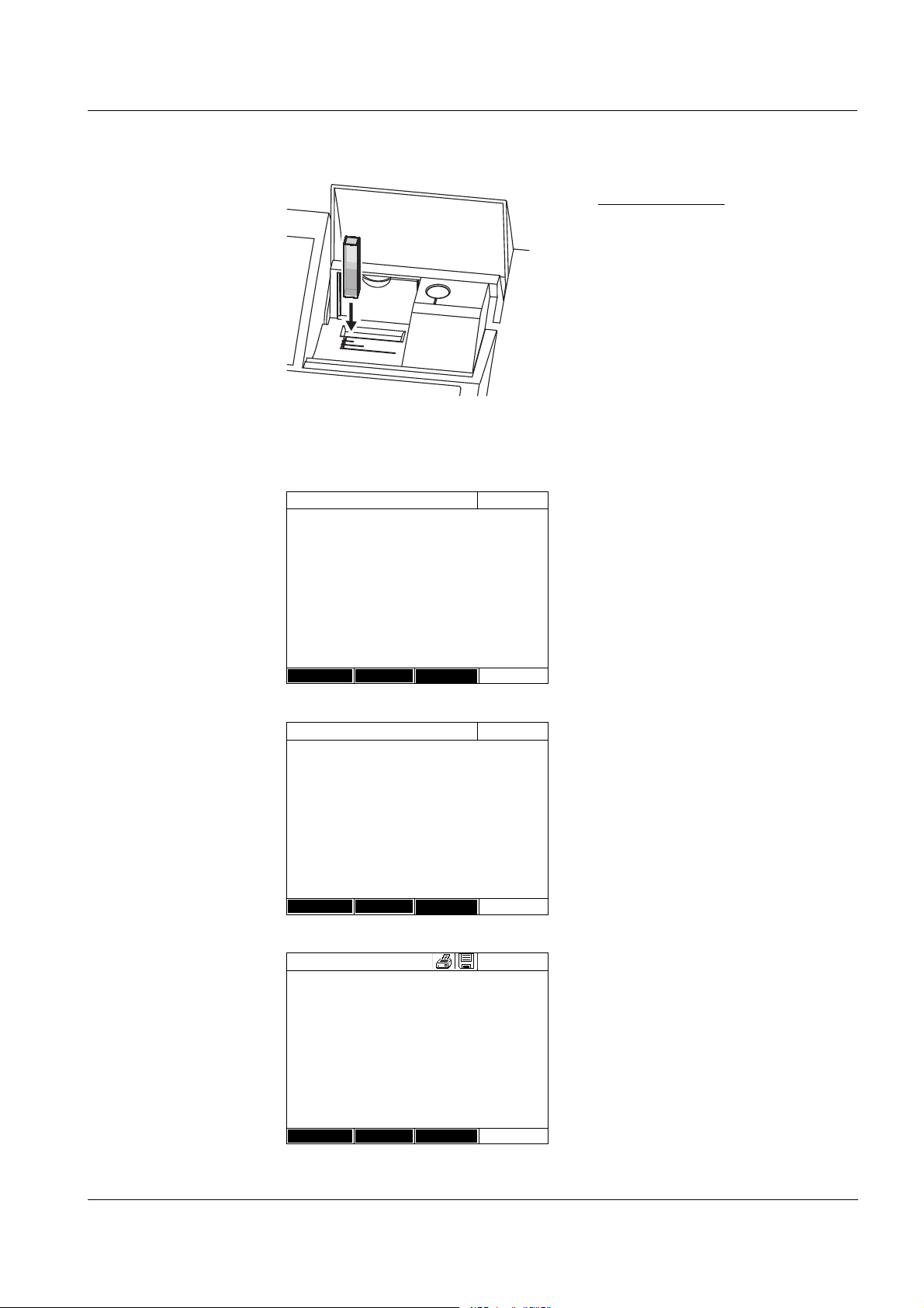
photoLab®6100 VIS Operation
Multi wavelengths
04/16/07 9:52
Zero adjustment successful
2001:PROT 10 mm
Setup
Method list
Transmission
Multi wavelengths
04/16/07 9:52
To start measurement,
insert cell or press <Start/Enter>
2001:PROT
Protein
10 mm
Setup
Method list
Transmission
Multi wavelengths
04/16/07 9:52
A(280 nm) = 2.220 A(260 nm) = 0.925
2.738
mg/ml
2002: PROT Protein
10 mm
Setup
Method list
Transmission
Rectangular cell:
Open the inner turn-up lid.
Insert the rectangular cell
vertically so it touches the bottom
and left edge of the cell shaft. The
opaque sides of the rectangular
cell must point to the front and
back.
The photometer has an external
light recognition. If there is too
much external light, a message
prompts you to close the cell shaft
cover.
If necessary, carry out a zero
measurement.
ba75847e01 08/2009
The photometer is ready to
measure.
The photometer starts measuring
automatically.
If necessary, switch over to
transmission display (%) with
[Transmission].
79
Page 80

Operation photoLab®6100 VIS
4.8 Spectrum
4.8.1 General information
With the Spectrum function, the absorbance or Transmission in dependency
of the wavelength is measured and recorded. The wavelength range can be
freely selected within the measuring range of the photometer. The increment
is 1 nm.
A spectrum is recorded without using any methods or profiles. All settings are
configured during measurement.
Baseline A baseline has to be recorded before a spectrum is recorded. The baseline
has to cover at least the wavelength range of the spectrum to be recorded.
Once the baseline is measured, it remains stored in the photometer until
z a new baseline is recorded
z the Spectrum mode is exited or the photometer is switched off
Settings You can record a spectrum with standard settings without opening the setting
window.
The following settings are possible for a spectrum:
Input field Possible entries
Wavelength start 320* ... 1100 nm
Wavelength stop 320 ... 1100* nm
Mode Absorbance* or
Transmission
Smoothing Yes* or No
Scaling Auto* or Manual
Scaling: Auto* During measurement, the instrument adjusts the
axis scaling (minimum and maximum value of the
axis) to the measured values. The entire curve is
always visible.
Scaling:Manual
Y-axis min
The axis scaling (minimum and maximum value of
the axis) is set manually.
Y-axis max
* default setting
80
Note
You can store the settings as profile with [Save] .
You can load a stored profile with [Open].
Profiles have the file extension "*.profil".
ba75847e01 08/2009
Page 81

photoLab®6100 VIS Operation
<HOME>
Spectrum
Spectrum
04/16/07 9:52
Wavelength [nm]
Setup Open
Absorbance
Spectrum
You have to record a baseline first
(<ZERO>).
Adjustment of wavelength range under
<General setup>.
Spectrum
04/16/07 9:52
Wavelength start 320 nm
Wavelength stop 1100 nm
Mode Absorbance
Cursor All values
Smoothing Yes
Scaling Auto
Apply
Spectrum
04/16/07 9:52
Wavelength [nm]
Setup Open
Absorbance
Spectrum
You have to record a baseline first
(<ZERO>).
Adjustment of wavelength range under
<General setup>.
4.8.2 Recording the Spectrum
A message containing operating
instructions is displayed.
1 Open the setting menu with
[Setup].
2 Select the start and end point of
the spectrum to be recorded and
the mode (Absorbance or
Transmission).
3 Accept all entries with [Apply].
A message containing operating
instructions is displayed.
ba75847e01 08/2009
81
Page 82

Operation photoLab®6100 VIS
Spectrum
04/16/07 9:52
Wavelength [nm]
Absorbance
Spectrum
04/16/07 9:52
Wavelength [nm]
Setup Open
Absorbance
Spectrum
Start measurement with <Start/Enter>
inner
turn-up lid
Recording the baseline:
4 Press the <ZERO·BLANK> key.
The photometer records the
baseline.
5 Wait until the baseline is
completely recorded.
The photometer is ready to
measure after the baseline has
been recorded.
Recording the spectrum:
6 Depending on the type, insert the
cell as follows:
Round cell:
Insert the round cell in the round
cell shaft so it touches the bottom.
7 Close the inner turn-up lid.
8 Start the measurement with
<START·ENTER>.
After the spectrum has been
recorded, the following message
appears: Recording of spectrum is
completed.
82
ba75847e01 08/2009
Page 83

photoLab®6100 VIS Operation
Spectrum
04/16/07 9:52
Wavelength [nm]
Setup Edit Zoom Open
Absorbance
Spectrum
04/16/07 9:52
Wavelength [nm]
Setup Edit Zoom Open
Absorbance
Cursor information
Rectangular cell:
Open the inner turn-up lid.
Insert the rectangular cell
vertically so it touches the bottom
and left edge of the cell shaft. The
opaque sides of the rectangular
cell must point to the front and
back.
9 Close the cell shaft cover.
10 Start the measurement with
<START·ENTER>.
11 Wait until the spectrum is
completely recorded.
At the end of the recording the
following message appears:
Recording of spectrum is
completed.
12 Confirm the message with
<START·ENTER>.
The cursor appears at the
absolute maximum of the
spectrum.
13 You have the following options:
- Immediately edit the spectrum
(see section 4.8.3)
-With <PRINT>, you can output
the spectrum to a connected
printer as a graphic.
- You can save the spectrum as a
*.csv file with <STORE>. As the
storage location, you can select
the photometer (Internal DataB
folder) or a USB memory device
connected to the USB-A
connection (USB memory).
Stored spectra can be recalled
and edited at any time (see
section 4.8.3).
ba75847e01 08/2009
83
Page 84

Operation photoLab®6100 VIS
<HOME>
Spectrum
– [Open]
Open (Internal DataB folder)
04/16/07
26.02.07 Holmium.csv
23.02.07 K2Cr2O7_340nm.csv
Location
Delete
Spectrum
04/16/07 9:52
Wavelength [nm]
Setup Edit Zoom Open
Absorbance
Cursor information
4.8.3 Loading/editing a spectrum
A spectrum can be edited immediately after measurement. Stored spectra
can be loaded and edited as well.
The following tools are available for editing:
z Cursor function for incremental moving along the curve with indication of
the x and y values
z Zoom function to scale up a section
z Mathematical functions for various evaluating and calculating operations.
The functions are described from page 86.
Loading a stored
spectrum
Cursor
The list with the spectra stored in
the exchange memory is
displayed.
1 If necessary, you can select a
different memory location for the
spectrum with [Location] (USB
memory device at the USB-A
connection).
2 Select the required spectrum.
The original view of the curve is
displayed.
The cursor consists of a horizontal
and vertical line that cross each
other on a point of the curve. A box
names the x and y values of the
point of the curve.
Move the cursor along the x axis
(wavelength) with <W><X>. You
can scan and evaluate the curve
point after point.
84
ba75847e01 08/2009
Page 85

photoLab®6100 VIS Operation
Spectrum
04/16/07 9:52
Wavelength [nm]
Setup xy min
Absorbance
Spectrum
04/16/07 9:52
Wavelength [nm]
Setup xy min
Absorbance
Spectrum
04/16/07 9:52
Wavelength [nm]
Setup xy max
Absorbance
Spectrum
04/16/07 9:52
Wavelength [nm]
Setup Edit Zoom Open
Absorbance
Zoom
1 Press [Zoom].
The zoom window appears. The
bottom left corner of the zoom
window is marked by a small black
square.
– You can return to the original
view of the spectrum with
[Original] at any time.
2 Adjusting the zoom window:
– Define the bottom left corner of
the zoom window with <W><X>
and <▲><▼>.
–Use [xy max] to mark the top
right corner of the zoom window
(small black square).
– Define the top right corner of the
zoom window with <W><X>
and <▲><▼>.
3 Scaling up the zoom window:
– Press the <START·ENTER>
key. The zoom window is scaled
up on the entire diagram area.
Leaving the zoom view:
– You can return to the original
view of the spectrum with
<ESC> at any time.
ba75847e01 08/2009
85
Page 86

Operation photoLab®6100 VIS
Edit Open the selection of mathematical functions with [Edit]:
z Extreme values (zoomed area)
Highlights the extreme values (minimum and maximum values) of the
displayed spectrum.
z Mark points
Opens an edit mode where you can highlight individual points of the
spectrum.
With the [Mark] function key you can highlight individual points.
The wavelength and measured valued are displayed at the highlighted
point.
With the [Delete] function key you can remove individual points.
z Delete all marks
Erases all highlighted points in the spectrum.
z Original
Displays the original, unedited spectrum.
z Integral
Calculates the area between the zero line and curve within a freely
selectable wavelength interval [X1,X2].
z Derivative
Calculates the derivative of the total spectrum. To calculate the second
and third derivative, the function can be carried out several times.
z Compare spectrum
Loads a second spectrum into the same diagram for direct comparison.
z Add spectrum
Adds a stored spectrum to the current spectrum.
z Subtract spectrum
Subtracts a stored spectrum from the current spectrum.
z Divide spectrum (ratio)
Divides the absorbance or % transmission values of the current spectrum
by the values of a stored spectrum
z Add fixed value
Adds a constant absorbance or % transmission value to the current
spectrum.
z Multiply fixed value
Multiplies the absorbance or % transmission values of the current
spectrum by a constant value.
Note
The addition, subtraction and division of two spectra always applies to the
common wavelength range of both spectra only.
86
ba75847e01 08/2009
Page 87

photoLab®6100 VIS Operation
Spectrum
04/16/07 9:52
Wavelength [nm]
Setup Edit Zoom Open
Absorbance
4.8.4 Saving / exporting a spectrum
The saving of a spectrum saves both the edited and the original spectrum.
Consequently, the original spectrum can be restored from each stored
spectrum.
Saving
1 Record a spectrum (see section
4.8.2)
or
Load a stored spectrum (see
section 4.8.3).
2 If necessary, connect a USB
memory device to the USB-A
interface.
3 Open the save dialog with
<STORE>.
4 If necessary, change the storage
location with [Location]:
Internal DataB folder:
Exchange folder in the instrument
or
USB memory:
USB memory device connected at
the USB-A connection.
5 If necessary, change the file
name.
6 Save the file with
<START·ENTER>.
Export to a PC Export a stored spectrum to a PC: see section 4.12.3
ba75847e01 08/2009
87
Page 88

Operation photoLab®6100 VIS
4.9 Kinetics
The Kinetics function enables the temporal tracing of the absorbance or
transmission of a sample at a certain wavelength.
The photometer automatically calculates the slope between two adjacent
measuring points from the available measurement data.
The catalytic activity can also be determined and displayed if required.
To record the kinetics, the photometer carries out single measurements at
regular intervals (measuring interval) and stores the measured values as a
time function.
All settings for a recording are administrated as a profile. Profiles can be
created, stored, edited and deleted. Each measurement requires a
respective profile.
4.9.1 Creating/editing profiles for kinetic records
Note
Profiles for kinetic records are stored under the numbers 4001 to 4020.
In the delivery condition, a profile is stored for demonstration purposes.
A profile for a kinetic recording comprises the following data:
Input field Possible entries
Number * 4001 ... 4020
Name Any name (max. 18 characters)
Mode* Absorbance or Transmission
Wavelength* Freely selectable (in nm)
Duration* Total duration in the format hh:mm:ss
(hours:minutes:seconds)
Interval* Measuring interval = time interval between two
successive single measurements in the format
hh:mm:ss (hours:minutes:seconds)
Exception:
With the setting, Measurements/interval: Max/
interval the interval is defined differently (see
below).
88
Delay Time between the start of the recording and the
start of the first single measurement
Scaling Auto or Manual
ba75847e01 08/2009
Page 89

photoLab®6100 VIS Operation
Cat. A. = mean value Slope [Δ/min] * Factor
Input field Possible entries
Scaling: Auto** During measurement, the instrument adjusts the
axis scaling (minimum and maximum value of the
axis) to the measured values. The entire curve is
always visible.
Scaling:Manual
Y-axis min
The axis scaling (minimum and maximum value of
the axis) is set manually.
Y-axis max
Measurements/interval 1/interval or Max/interval
Here you define how many measurements are
carried out per interval.
This setting has an impact on the calculation of the
slope of the individual intervals (see section
4.9.6).
Catalytic activity Yes or No
Here you determine whether the catalytic activity
should be calculated.
The catalytic activity is a measure for the amount
of substance that is converted per time unit.
To accelerate the substance conversion, a
catalyst or enzyme (biological catalyst) is used in
most cases.
Catalytic activity:Yes
Factor
Unit
The catalytic activity or enzymatic activity is
calculated from the slope of the curve.
Resolution
* necessary inputs
** default: Auto
ba75847e01 08/2009
Here you can enter the value for Factor.
The calculated value for the catalytic activity is
displayed in the menu, [Edit] / Slope, together with
the unit and resolution selected here.
89
Page 90

Operation photoLab®6100 VIS
<HOME>
Kinetics
– [Setup]
– Edit profile
Edit profile (1 of 2)
04/16/07 9:52
Number 4001
Name NADH
Mode Absorbance
Wavelength 340 nm
Duration 02:00:00
Interval 00:00:30
Delay 00:01:00
Scaling Auto
Profile Delete Next
Edit profile (1 of 2)
04/16/07 9:52
Measurements/interval
1/interval
Katalytic activity Yes
Factor 1.000
Unit cat
Resolut ion 0.01
Back Complete
Creating/editing a
profile
1 Enter the data for the profile here.
The next available profile number
is already entered as the number.
You have the following options
when filling out the input fields:
- Fill out all empty input fields one
after the other
- Using [Profile], select an
already existing profile as a
model, give it a new profile
number and adjust the entries
90
- Using [Profile], select an
existing profile in order to
change it (without changing the
number).
- You can delete the profile
completely with [Delete].
2 With [Next] you can switch to
further settings.
3 Enter further data for the profile
here.
4 Accept all entries with [Complete].
The profile is created and
selected. The photometer is ready
to measure.
Note
The Catalytic activity function is only available if the Absorbance mode was
selected.
ba75847e01 08/2009
Page 91

photoLab®6100 VIS Operation
<HOME>
Kinetics
– [Profile]
Select profile (all)
04/16/07 9:52
4001 NADH Absorbance
4002 ADH Absorbance
Last used
Select profile (last used)
04/16/07 9:52
4001 NADH Absorbance
All profiles
NA_
4.9.2 Loading a profile for kinetic recording
To load a profile for kinetic recording, proceed as follows:
The list of profiles is displayed.
The profiles are ordered according
to the profile number.
Selecting a profile:
1 Select the required profile with
<▲><▼>. The active selection is
displayed in reverse video.
Narrowing down the
list of profiles
Search function
2 Accept the selection with
<START·ENTER>.
The photometer is ready to
measure.
If the list is very long, you can narrow down the profile list and thus make the
search easier as follows:
z Using [Last used], you can restrict the profile list to the ten profiles last
used.
z With the search function you can search certain character strings in the
list. The search takes place as a full-text search of the entire list contents.
Thus you can search for a profile number or name.
Search for a character string:
Enter the character string to be
searched for in the search window
with <A...9>.
The list appearing below shows all
hits containing the character
string. The hit list is updated with
each character that is entered.
ba75847e01 08/2009
Note
Note the case sensitivity when searching.
91
Page 92

Operation photoLab®6100 VIS
<HOME>
Kinetics
Kinetics
04/16/07 9:52
Please select a profile for measuring!
Setup Profile Open
Kinetics
04/16/07 9:52
To start measurement,
insert cell or press <Start/Enter>
4002
Absorbance
Setup Profile Open
inner
turn-up lid
4.9.3 Recording the Kinetics
Note
During the recording, the photometer cannot carry out any regular self-test or
self-calibration (AutoCheck), because the recording would have to be
interrupted for this. A warm-up time of at least two hours is required for the
photometer to measure reliably during the recording.
Note the warm-up time of at least
2 hours for kinetic recordings.
1 Select the required profile with
[Profile] (see section 4.9.2).
The photometer is ready to
measure after the profile has been
selected.
2 Depending on the type, insert the
cell as follows:
Round cell:
Insert the round cell in the round
cell shaft so it touches the bottom.
If the inner turn-up lid is opened
too wide, a message prompts you
to close the inner turn-up lid.
92
ba75847e01 08/2009
Page 93

photoLab®6100 VIS Operation
Kinetics
04/16/07 9:52
4002 Number of measurements: 4
Duration: 00:00:24 Interval:00:00:06
Time [s]
Stop
Absorbance
Rectangular cell:
Open the inner turn-up lid.
Insert the rectangular cell
vertically so it touches the bottom
and left edge of the cell shaft. The
opaque sides of the rectangular
cell must point to the front and
back.
The photometer has an external
light recognition. If there is too
much external light, a message
prompts you to close the cell shaft
cover.
The photometer starts recording
automatically.
3 Wait until the recording is finished.
Stopping the recording:
-Use [Stop] to terminate the
recording prematurely. The
curve recorded up to this point
can be stored and edited (see
section 4.9.6).
-Use <ESC> to completely
cancel measurement. The
curve recorded up to this point
is discarded.
ba75847e01 08/2009
93
Page 94

Operation photoLab®6100 VIS
Kinetics
04/16/07 9:52
4002 Number of measurements: 4
Duration: 00:00:24 Interval:00:00:06
Time [s]
Setup Profile Edit Open
Absorbance
Cursor information
4 After the specified Duration has
expired, the cursor appears.
You have the following options:
- You can move the cursor along
the curve and have the
measurement data for each
point displayed (see section
4.9.6)
-With <PRINT>, you can output
the kinetic curve to a connected
printer as a graphic.
- You can store the kinetic curve
with <STORE> (see section
4.9.4).
- Execute further functions to edit
the kinetic record (see section
4.9.6)
- Close the kinetic record with
<ESC>.
94
ba75847e01 08/2009
Page 95

photoLab®6100 VIS Operation
Kinetics
04/16/07 9:52
4002 Number of measurements: 4
Duration: 00:00:24 Interval:00:00:06
Time [s]
Setup Profile Edit Open
Absorbance
4.9.4 Saving / exporting a kinetic record
Saving
1 Carry out the kinetic recording
(see section 4.9.3)
or
Load a stored kinetic record (see
section 4.9.4).
2 If necessary, connect a USB
memory device to the USB-A
interface.
3 Open the save dialog with
<STORE>.
4 If necessary, change the storage
location with [Location]:
Internal DataB folder:
Exchange folder in the instrument
or
USB memory:
USB memory device connected at
the USB-A connection.
5 If necessary, change the file
name.
Export to a PC Export a stored kinetic record to a PC: see section 4.12.3
6 Save the file with
<START·ENTER>.
ba75847e01 08/2009
95
Page 96

Operation photoLab®6100 VIS
<HOME>
Kinetics
– [Open]
04/16/07
26.02.07 Enzyme kinetics.csv
24.02.07 ADH.csv
24.02.07 kinetics_4002_070224_1410.csv
Location
Delete
Kinetics
04/16/07 9:52
4002 Number of measurements: 4
Duration: 00:00:24 Interval:00:00:06
Time [s]
Setup Edit Open
Absorbance
4.9.5 Loading a kinetic record
You can load and view stored kinetic records.
Loading a stored
Kinetics record
The list with the stored kinetic
records is displayed (Internal
DataB folder).
1 With [Location] select the memory
location of the kinetic record
(Internal DataB folder or USB
memory for a USB memory device
at the USB-A connection).
2 Select the required kinetic record.
The curve is loaded.
You have the following options:
- You can move the cursor along
the curve and have the
measurement data for each
point displayed (see section
4.9.6)
-With <PRINT>, you can output
the kinetic curve to a connected
printer as a graphic.
- You can store the kinetic curve
with <STORE> (see section
4.9.4).
- Execute further functions to edit
the kinetic record (see section
4.9.6)
- Close the kinetic record with
<ESC>.
96
ba75847e01 08/2009
Page 97

photoLab®6100 VIS Operation
Kinetics
04/16/07 9:52
4002 Number of measurements: 4
Duration: 00:00:24 Interval:00:00:06
Time [s]
Setup Edit Open
Absorbance
Cursor information
Kinetics
04/16/07 9:52
0.63
cat
Interval Slop e (Δ/min) Time
1 0.000 5 s
2 0.000 10 s
3 0.000 15 s
4 0.000 20 s
5 0.000 25 s
6 0.000 30 s
Back
4.9.6 Editing a kinetic record
The following functions are available for kinetic records:
z Moving along the curve with the cursor
z Displaying a list with the slopes of the curve for each interval
z Scaling the Y-axis of the diagram
z Combined display of two kinetic records in one graphic
z Display of the difference of two kinetic records
Cursor
Slope of the curve &
catalytic activity
The cursor consists of a horizontal
and vertical line that cross each
other on a point of the curve. A box
names the x and y values of the
point of the curve.
Move the cursor along the x axis
(time axis) with <W><X>. You can
scan and evaluate the curve point
after point.
The function, Slope indicates the slope of the kinetic curve in the individual
intercepts (intervals) of the curve.
An intercept corresponds to the Interval entered in the profile.
1 Indicate the slope of the kinetic
curve in the individual intercepts
(intervals) of the curve with [Edit] /
Slope.
ba75847e01 08/2009
If the calculation of the catalytic
activity was selected when the
profile was created it is displayed
here together with the slope.
97
Page 98

Operation photoLab®6100 VIS
Note
The Slope function is only available if the kinetic recording was done in the
Absorbance mode.
The displayed slope for an interval is determined as follows, depending on
the slope:
Measurements/interval Slope
1/interval Slope,
converted to the interval, "1 minute"
Max/interval Slope of the straight line determined by linear
regression in an interval, converted to the
interval, "1 minute"
Scaling of the Y-axis You can manually determine the scaling of the Y-axis with [Setup]/Scaling/
Manual.
Compare kinetics For direct comparison, you can load a second kinetic record into the same
diagram with [Edit] / Compare kinetics.
Note
The Compare kinetics function can only be carried out if both kinetic records
were made in the Absorbance mode.
Subtract kinetics You can subtract a stored kinetic record from the current kinetic record with
[Edit] / Subtract kinetics.
Note
The Subtract kinetics can only be carried out if both kinetic records were
made with the following settings:
z Mode: Absorbance
z Measurements/interval:1/interval
z Equal interval
98
ba75847e01 08/2009
Page 99

photoLab®6100 VIS Operation
4.10 Timer
You can use the timers to remind you by an acoustic signal of a time interval
that has expired.
The photometer has two types of timers:
z The User defined timer is a timer that can be freely assigned. The interval
and name can be freely set. Only one freely assignable timer is available.
It cannot be erased (see section 4.10.1).
z Analysis timer are timers permanently stored in the photometer. The
names and intervals of the analysis timers are stored in the method data
of a measuring method (Concentration mode). The number of available
analysis timers corresponds to the number of reaction times prescribed in
the analysis instructions of the programmed methods (see section 4.10.2).
The photometer administrates all timers in the timer overview.
The timer overview (the Timer menu) is opened with the <TIMER> key. The
Timer menu can be opened in any operating situation.
Operation of the timer does not disturb any other functions.
The timer overview can be exited with the <ESC> key.
When the Timer menu is opened for the first time, only the user-defined timer
is in the timer overview. You can include analysis timers into the list or
remove them according to your requirements (see section 4.10.2).
The timer overview displays the status of each timer and, of a started timer,
the remaining time of the specified time interval.
All timers are started manually.
As soon as one single timer has been started the timer symbol appears on
the display in all operating modes.
When a timer has been started it is given the timer status, Active.
When the specified time interval has expired the timer status changes from
Active to Expired and an acoustic signal sounds.
In the timer status Expired the acoustic signal sounds until the timer is
stopped manually.
After the stop, the timer status changes to Inactive and the acoustic signal is
switched off.
ba75847e01 08/2009
99
Page 100

Operation photoLab®6100 VIS
<TIMER>
Timer
04/16/07 9:52
Designation Time Status
User defined timer 00:15:00 Inactiv
A6/25 - 1 00:15:00 Inactiv
Start Stop Edit Add
4.10.1 User defined timer
If you want to manually enter time intervals, use the User defined timer
function.
The Timer menu is open.
1 Highlight the User defined timer.
2 If necessary, change the name
and time of the timer with [Edit].
3 Start the highlighted timer with
[Start].
The status of the timer is Active.
When the specified time interval
has expired, an acoustic signal
sounds and the status changes to
Expired.
4 Stop the highlighted timer with
[Stop].
The status of the timer changes to
Inactive. The acoustic signal is
switched off.
4.10.2 Analysis timer
Between the individual steps of a measurement, reaction times often have to
be observed. The length of the reaction time is defined in the relevant
analysis instructions.
For all required reaction times, the analysis timers with the corresponding
time intervals are stored in the instrument. The names of the analysis timers
include the method name and a current number so several timers within a
method can be distinguished from each other.
To be able to use an analysis timer for a method you have to load it in the
timer overview first.
To do so, first select the required method and then add the available analysis
timers to the timer overview so they can be started as necessary.
The timer overview always comprises the free timer and the selected analysis
timers.
100
ba75847e01 08/2009
 Loading...