

Page 1
Turb 430 IR
Turb 430 T
Operating manual
ba75507e02 12/2005
Handheld Turbidimeter
Page 2

Turb 430 IR/T
Accuracy when
going to press
Firmware
Operating manual
The use of advanced technology and the high quality standard of our
instruments are the result of continuous development. This may result
in differences between this operating manual and your instrument.
Also, we cannot guarantee that there are absolutely no errors in this
manual. Therefore, we are sure you will understand that we cannot
accept any legal claims resulting from the data, figures or descriptions.
Part of the process of consequently improving our products is the
continuos further development of instrument firmware. All current data
for the Turb 430 IR/T can be found on the Internet under http://
www.WTW.com:
! Firmware
! Operating manual
You can easily transfer new firmware to your instrument with the aid of
the AK 540/B cable and a PC. More detailed information can be found
in the appendix of the detailed operating manual on the CD-ROM
provided.
Copyright
© 2005, WTW GmbH
Reprinting - even as excerpts - is only allowed with the explicit written
authorization of WTW GmbH, Weilheim.
Printed in Germany.
2
ba75507e02 12/2005
Page 3

Turb 430 IR/T Contents
1 Overview . . . . . . . . . . . . . . . . . . . . . . . . . . . . . . . . . . . . . . 5
1.1 General features . . . . . . . . . . . . . . . . . . . . . . . . . . . . . . . 5
1.2 Keypad . . . . . . . . . . . . . . . . . . . . . . . . . . . . . . . . . . . . . . . 6
1.3 Display . . . . . . . . . . . . . . . . . . . . . . . . . . . . . . . . . . . . . . . 7
1.4 Socket field . . . . . . . . . . . . . . . . . . . . . . . . . . . . . . . . . . . . 7
1.5 LabStation (optional) . . . . . . . . . . . . . . . . . . . . . . . . . . . . 8
2 Safety . . . . . . . . . . . . . . . . . . . . . . . . . . . . . . . . . . . . . . . . 9
2.1 Authorized use . . . . . . . . . . . . . . . . . . . . . . . . . . . . . . . . 10
2.2 General safety instructions . . . . . . . . . . . . . . . . . . . . . . . 10
3 Commissioning . . . . . . . . . . . . . . . . . . . . . . . . . . . . . . . 13
3.1 Scope of delivery . . . . . . . . . . . . . . . . . . . . . . . . . . . . . . 13
3.2 Power supply . . . . . . . . . . . . . . . . . . . . . . . . . . . . . . . . . 13
3.3 Connecting the LabStation . . . . . . . . . . . . . . . . . . . . . . . 15
3.4 Initial commissioning . . . . . . . . . . . . . . . . . . . . . . . . . . . 17
4 Operation . . . . . . . . . . . . . . . . . . . . . . . . . . . . . . . . . . . . 19
4.1 Switching on the meter . . . . . . . . . . . . . . . . . . . . . . . . . . 19
4.2 Inserting a cell . . . . . . . . . . . . . . . . . . . . . . . . . . . . . . . . 20
4.3 General operating principles . . . . . . . . . . . . . . . . . . . . . 21
4.3.1 Operating modes . . . . . . . . . . . . . . . . . . . . . . . . 21
4.3.2 Navigation . . . . . . . . . . . . . . . . . . . . . . . . . . . . . 21
4.3.3 Navigation example 1: setting the language . . . 24
4.3.4 Navigation example 2: setting the date and time 25
4.3.5 Menu overview . . . . . . . . . . . . . . . . . . . . . . . . . 26
4.4 System settings (System menu) . . . . . . . . . . . . . . . . . . 28
4.4.1 Measured value memory . . . . . . . . . . . . . . . . . . 29
4.4.2 Display . . . . . . . . . . . . . . . . . . . . . . . . . . . . . . . 31
4.4.3 Interface . . . . . . . . . . . . . . . . . . . . . . . . . . . . . . 31
4.4.4 Date/time . . . . . . . . . . . . . . . . . . . . . . . . . . . . . . 32
4.5 Turbidity . . . . . . . . . . . . . . . . . . . . . . . . . . . . . . . . . . . . . 33
4.5.1 General information . . . . . . . . . . . . . . . . . . . . . . 33
4.5.2 Aligning and marking a cell . . . . . . . . . . . . . . . . 33
4.5.3 Measuring turbidity . . . . . . . . . . . . . . . . . . . . . . 34
4.5.4 Settings for turbidity measurements . . . . . . . . . 36
4.5.5 Calibration . . . . . . . . . . . . . . . . . . . . . . . . . . . . 36
4.6 Saving . . . . . . . . . . . . . . . . . . . . . . . . . . . . . . . . . . . . . . 40
4.6.1 Storing measurement datsets . . . . . . . . . . . . . . 40
4.6.2 Filtering measurement datsets . . . . . . . . . . . . . 41
4.6.3 Displaying measurement datsets . . . . . . . . . . . 42
4.6.4 Download the measurement datsets to the RS232
interface . . . . . . . . . . . . . . . . . . . . . . . . . . . . . . 42
4.6.5 Erasing stored measurement datasets . . . . . . . 43
4.7 Transmitting data (RS 232 interface) . . . . . . . . . . . . . . . 43
4.7.1 Connecting a PC/external printer . . . . . . . . . . . 44
ba75507e03 07/2006
3
Page 4

Contents Turb 430 IR/T
4.7.2 Configuring the RS232 interface . . . . . . . . . . . . 44
4.7.3 Selecting the output format of datasets . . . . . . . 45
4.7.4 Transmitting data . . . . . . . . . . . . . . . . . . . . . . . . 47
4.8 Reset . . . . . . . . . . . . . . . . . . . . . . . . . . . . . . . . . . . . . . . 48
4.8.1 Resetting the system settings . . . . . . . . . . . . . . 48
4.8.2 Resetting turbidimeter settings . . . . . . . . . . . . . 48
4.9 Meter information . . . . . . . . . . . . . . . . . . . . . . . . . . . . . . 49
4.10 Software update . . . . . . . . . . . . . . . . . . . . . . . . . . . . . . . 49
5 Maintenance, cleaning, disposal . . . . . . . . . . . . . . . . . 51
5.1 Maintenance . . . . . . . . . . . . . . . . . . . . . . . . . . . . . . . . . . 51
5.1.1 Inserting/exchanging the batteries . . . . . . . . . . . 51
5.1.2 Retrofitting the accumulator pack . . . . . . . . . . . 52
5.2 Cleaning . . . . . . . . . . . . . . . . . . . . . . . . . . . . . . . . . . . . . 53
5.2.1 Cleaning the cell shaft . . . . . . . . . . . . . . . . . . . . 53
5.2.2 Cleaning the cells . . . . . . . . . . . . . . . . . . . . . . . 53
5.3 Disposal . . . . . . . . . . . . . . . . . . . . . . . . . . . . . . . . . . . . . 54
6 What to do if... . . . . . . . . . . . . . . . . . . . . . . . . . . . . . . . . 55
6.1 General errors . . . . . . . . . . . . . . . . . . . . . . . . . . . . . . . . . 55
6.2 Turbidity . . . . . . . . . . . . . . . . . . . . . . . . . . . . . . . . . . . . . 55
7 Technical data . . . . . . . . . . . . . . . . . . . . . . . . . . . . . . . . 57
7.1 General data . . . . . . . . . . . . . . . . . . . . . . . . . . . . . . . . . . 57
7.1.1 Turb 430 IR/T . . . . . . . . . . . . . . . . . . . . . . . . . . . 57
7.1.2 LabStation . . . . . . . . . . . . . . . . . . . . . . . . . . . . . 58
7.2 Turbidity . . . . . . . . . . . . . . . . . . . . . . . . . . . . . . . . . . . . . 59
7.2.1 Turb 430 IR . . . . . . . . . . . . . . . . . . . . . . . . . . . . 59
7.2.2 Turb 430 T . . . . . . . . . . . . . . . . . . . . . . . . . . . . . 59
8 Accessories, options . . . . . . . . . . . . . . . . . . . . . . . . . . . 61
8.1 WTW accessories . . . . . . . . . . . . . . . . . . . . . . . . . . . . . . 61
8.1.1 Connection cable: . . . . . . . . . . . . . . . . . . . . . . . 61
9 Lists . . . . . . . . . . . . . . . . . . . . . . . . . . . . . . . . . . . . . . . . .63
10 Index . . . . . . . . . . . . . . . . . . . . . . . . . . . . . . . . . . . . . . . . 67
Appendix: Firmware update . . . . . . . . . . . . . . . . . . . . . . . . . 69
Appendix: Turbidity values under 1 FNU/NTU . . . . . . . . . .70
4
ba75507e03 07/2006
Page 5
Turb 430 IR/T Overview
1Overview
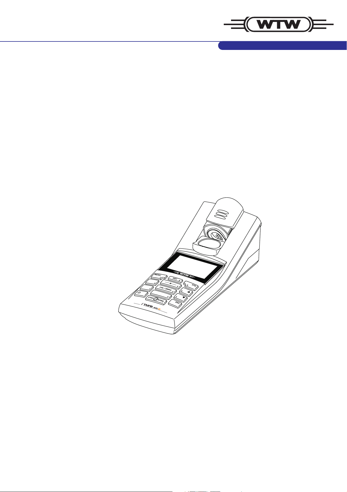
1.1 General features
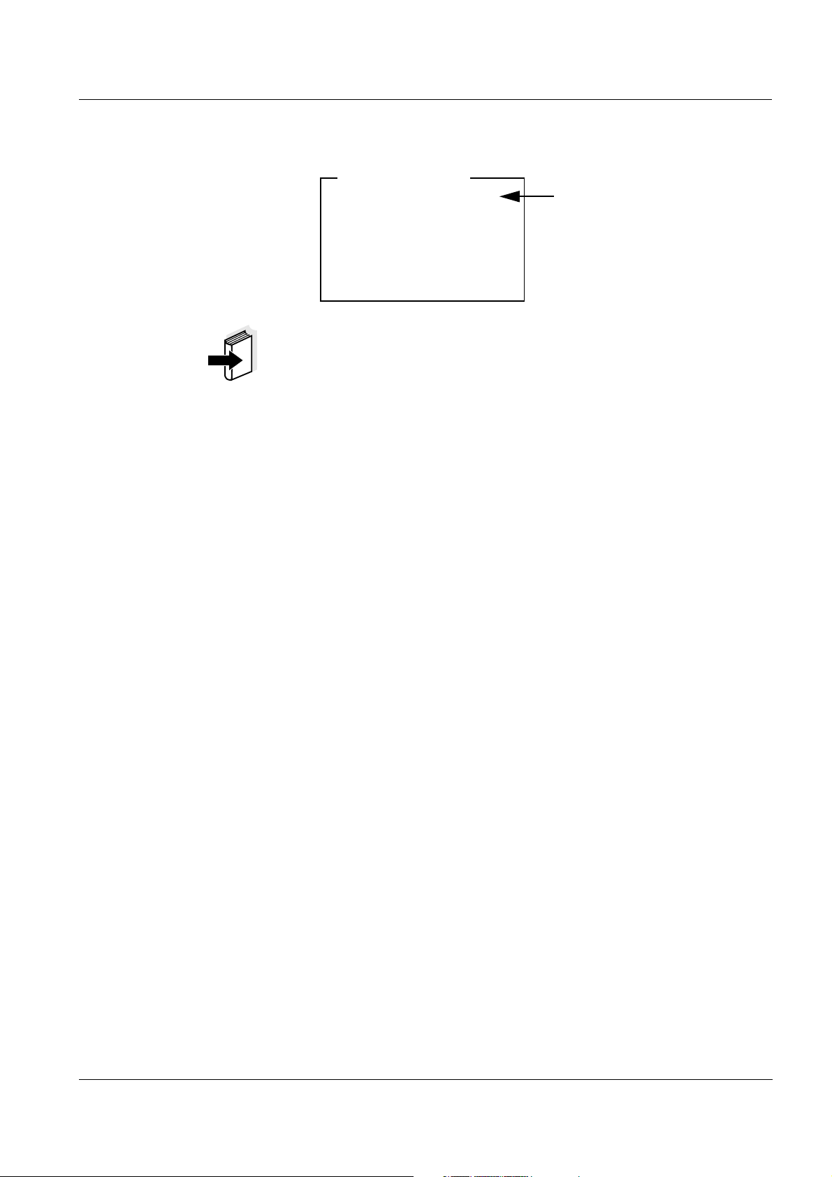
The compact Turb 430 IR/T handheld precision turbidimeter enables
you to carry out turbidity measurements quickly and reliably.
The Turb 430 IR/T handheld meter provides the maximum degree of
operating comfort, reliability and measuring certainty for all
applications.
4
3
2
1
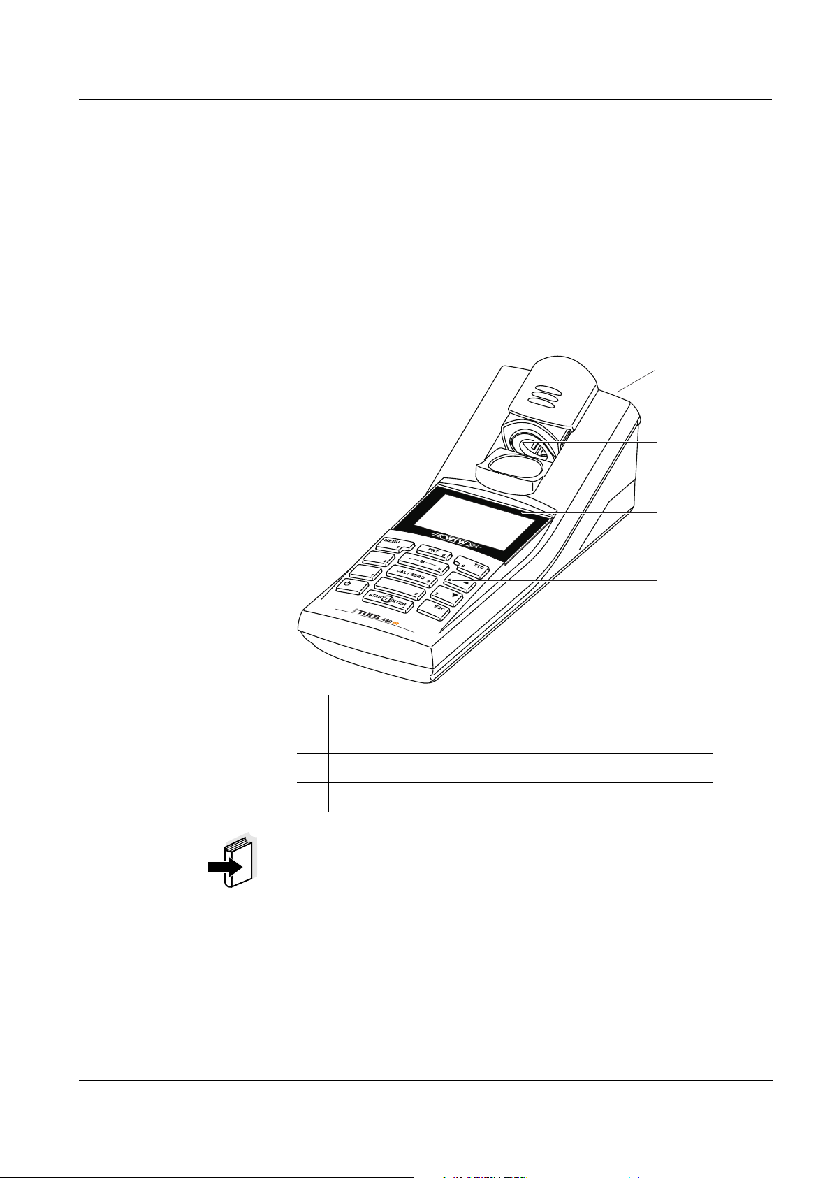
1 Keypad
2 Display
3 Cell shaft
4 Socket field
Note
If you need further information or application notes, you can obtain the
following material from WTW:
! Application reports
! Primers
ba75507e03 07/2006
! Safety datasheets.
Information on available literature is given in the WTW catalog or on the
Internet under www.WTW.com.
5
Page 6
Overview Turb 430 IR/T
1.2 Keypad
.
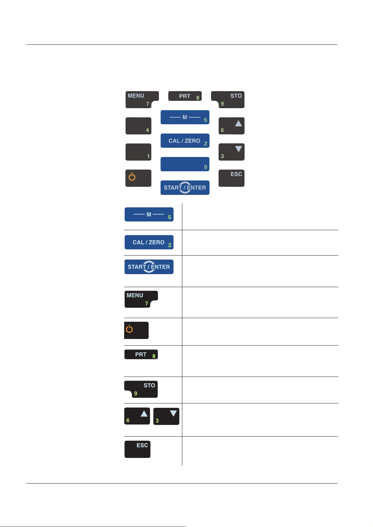
Key functions
PRT
Switch to the measured value display
<M>
Start calibration
<CAL/ZERO>
Open menus / confirm entries /
start measurement
.
<START/ENTER>
Call up the Configuration menu
(all settings are made here)
<MENU>
Switch the measuring instrument on/off
<ON/OFF>
Output display contents to RS232 interface (e.g.
print)
<PRT>
Open the Store menu: <STO>
Quick storing: 2 x <STO>
Highlight menu items or selection
Set values
<▲>, <▼>
Switch to the next higher menu level /
cancel input
<ESC>
6
ba75507e03 07/2006
Page 7
Turb 430 IR/T Overview
Note
Keys with an additional number printed on are assigned doubly.
This enables to directly enter numbers in special menus. Thus, you
can, for example, conveniently enter the date and time via the number
keys.
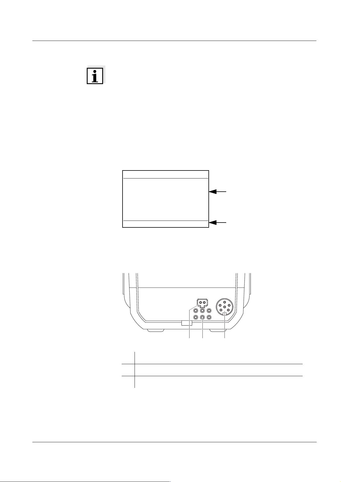
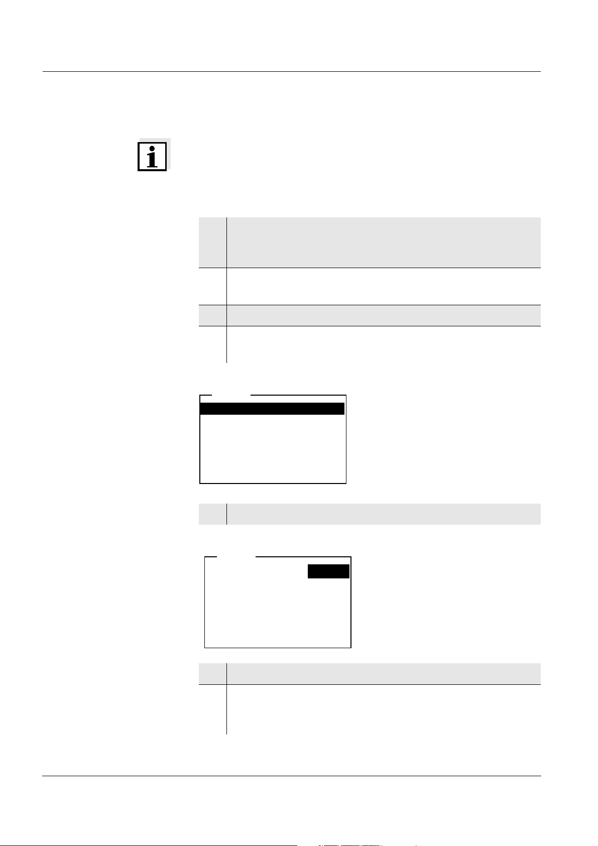
1.3 Display
The graphic display shows all information of the current measurement
in the measured value display. The illumination enables to read the
display even in the darkness.
Example
Turbidity
157.0
01.02.05 15:12
1.4 Socket field
FNU
NTU
Measured value (with unit)
Status line with date and time
Identifying the
connectors
ba75507e03 07/2006
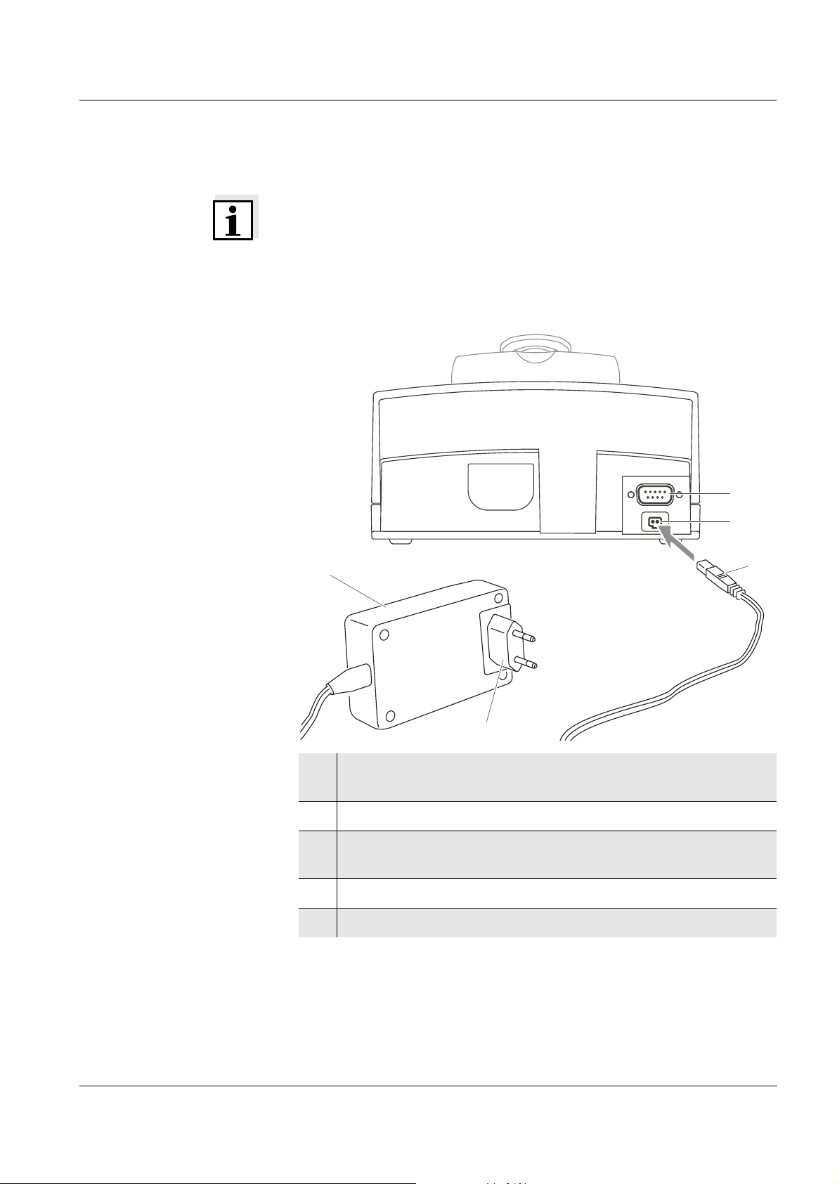
12 3
1 Power pack
2 Contacts for operation on the LabStation
3 RS232 serial interface
7
Page 8
Overview Turb 430 IR/T
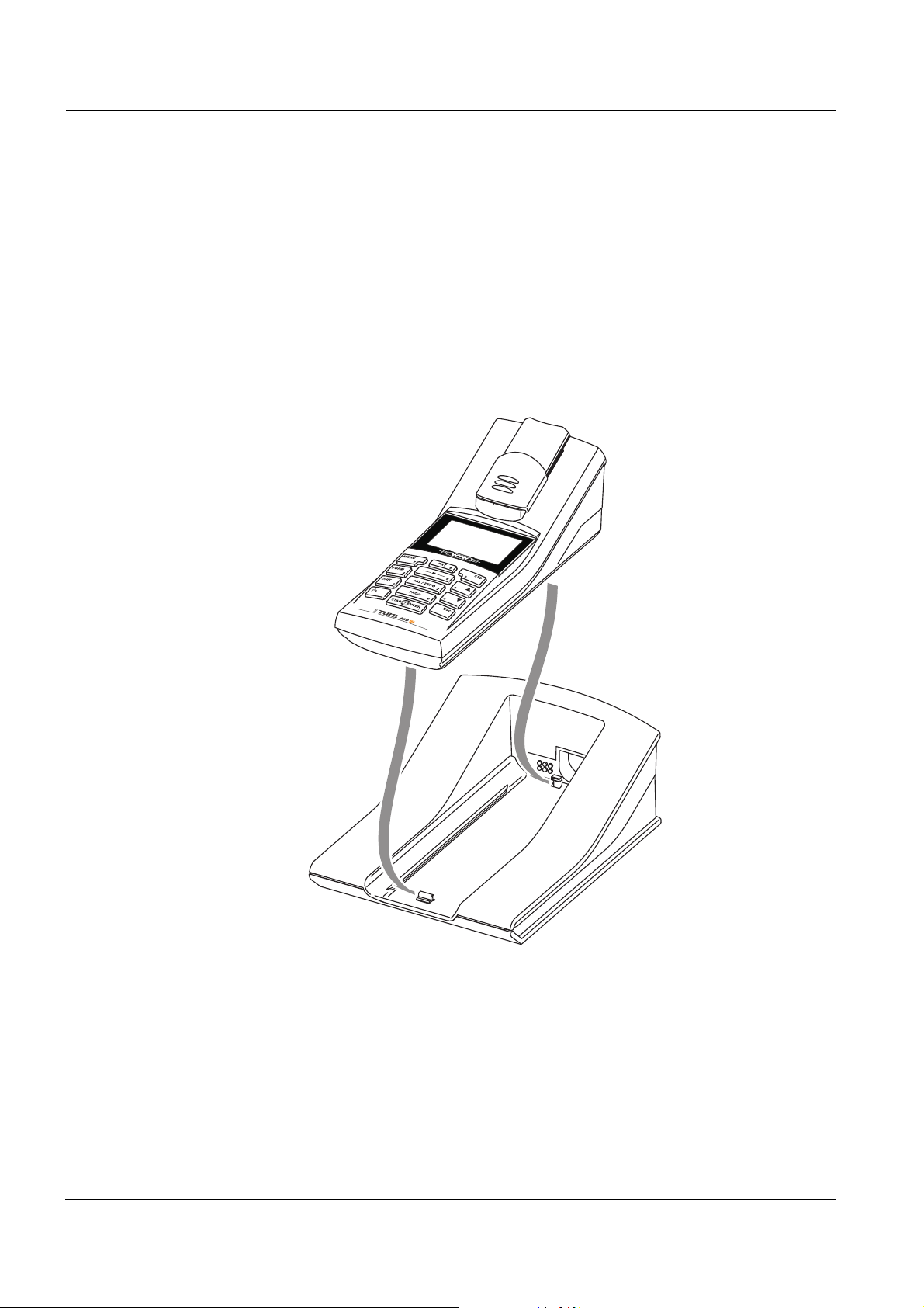
1.5 LabStation (optional)
With the LabStation, which is available as an accessory, you can
conveniently use the Turb 430 IR/T in the laboratory.
Laboratory operation with the LabStation enables the following
additional functions:
! Line power operation is possible to save the batteries or
accumulator pack
! The accumulator pack in the Turb 430 IR/T is automatically charged
as soon as the meter is placed in the LabStation.
LabStation
LabStation
8
ba75507e03 07/2006
Page 9
Turb 430 IR/T Safety
2 Safety
This operating manual contains basic instructions that you must follow
during the commissioning, operation and maintenance of the meter.
Consequently, all responsible personnel must read this operating
manual carefully before working with the meter. The operating manual
must always be available within the vicinity of the meter.
Target group The meter was developed for work in the field and in the laboratory.
Thus, we assume that, as a result of their professional training and
experience, the operators will know the necessary safety precautions
to take when handling chemicals.
The personnel responsible for the commissioning, operation and
maintenance must have the necessary qualifications for this work. If the
personnel do not have the required skills they have to be instructed.
Furthermore, it must be ensured that the personnel read and
completely understand the present operating manual.
Safety instructions Safety instructions in this operating manual are indicated by the
warning symbol (triangle) in the left column. The signal word (e.g.
"Caution") indicates the level of danger:
Caution
indicates instructions that must be followed precisely in order to
avoid the possibility of slight injuries or damage to the instrument
or the environment.
Further notes
Note
indicates notes that draw your attention to special features.
Note
indicates cross-references to other documents, e.g. operating
manuals.
ba75507e03 07/2006
9
Page 10

Safety Turb 430 IR/T
2.1 Authorized use
This meter is authorized exclusively for carrying out turbidity
measurements in the field and laboratory.
The technical specifications as given in chapter 7 T
ECHNICAL DATA must
be observed. Only the operation and running of the meter according to
the instructions given in this operating manual is authorized. Any other
use is considered to be unauthorized.
2.2 General safety instructions
This instrument is built and inspected according to the relevant
guidelines and norms for electronic measuring instruments (see
chapter 7 T
It left the factory in a safe and secure technical condition.
Opening the photometer or adjustment, maintenance and repair work
must only be performed by specialist personnel authorized by the
manufacturer.
The only exceptions to this are the activities described in chapter
5M
AINTENANCE, CLEANING, DISPOSAL. Non-compliance results in the
loss of warranty claims.
Follow the points listed below when operating the photometer:
ECHNICAL DATA).
Function and
operational safety
! Follow the local safety and accident prevention regulations
! Observe the enclosed instructions of reagents and accessories
! Observe the regulations when dealing with dangerous substances
! Follow the operating instructions at the workplace
! Use only original spare parts.
The smooth functioning and operational safety of the meter can only be
guaranteed if the generally applicable safety measures and the specific
safety instructions in this operating manual are followed during
operation.
The smooth functioning and operational safety of the meter can only be
guaranteed under the environmental conditions that are specified in
chapter 7 T
ECHNICAL DATA.
If the instrument was transported from a cold environment to a warm
environment, the formation of condensate can lead to the faulty
functioning of the instrument. In this event, wait until the temperature of
the instrument reaches room temperature before putting the instrument
back into operation.
10
ba75507e03 07/2006
Page 11

Turb 430 IR/T Safety
Safe operation It is the responsibility of the operator to continuously observe the
overall technical condition (externally recognizable deficits and
damage as well as alterations to the operational behavior) of the meter.
If safe operation is no longer possible, the instrument must be taken out
of service and secured against inadvertent operation!
Safe operation is no longer possible if the meter:
! has been damaged in transport
! has been stored under adverse conditions for a lengthy period of
time
! is visibly damaged
! no longer operates as described in this manual.
If you are in any doubt, please contact the supplier of the instrument.
Caution
Danger of eye damage by visible and invisible LED radiation. In
the cell shaft of the Turb 430 IR there are light emitting diodes
(LED) of the 1M class. Do not look at the radiation using optical
instruments. With normal, authorized use there is no hazard.
Obligations of the
purchaser
The purchaser of this meter must ensure that the following laws and
guidelines are observed when using dangerous substances:
! EEC directives for protective labor legislation
! National protective labor legislation
! Safety regulations
! Safety datasheets of the chemical manufacturers.
ba75507e03 07/2006
11
Page 12

Safety Turb 430 IR/T
12
ba75507e03 07/2006
Page 13
Turb 430 IR/T Commissioning
3 Commissioning
3.1 Scope of delivery
! Handheld turbidimeter Turb 430 IR or Turb 430 T
! 4 batteries, 1.5 V type AA (in the battery compartment)
! Optional: Accumulator pack and power pack with Euro plug
and exchange plugs for USA, UK, and Australia
! Optional: LabStation
! 5 empty cells 28 mm
with label to mark the cell
! AMCO
! Microfiber cloth to clean the meter
! Compact operating manual and short operating manual
! CD-ROM with detailed operating manual
®
-Clear turbidity standard
Charging time of the
accumulator pack
Note
The optional parts of the scope of delivery are available as accessories
(see section 8.1).
3.2 Power supply
You can operate the meter either with batteries, accumulator pack or a
power pack. The power pack supplies the meter with low voltage
(9 V DC). At the same time, the accumulator pack is charged. The
accumulator pack is charged even while the meter is switched off.
The LoBat display indicator appears when the batteries or accumulator
pack are nearly discharged.
approx. 36 hours.
Caution
The line voltage at the operating site must lie within the input
voltage range of the original power pack (
DATA).
SEE chapter 7 TECHNICAL
ba75507e03 07/2006
Caution
Use original power packs only (see chapter 7 TECHNICAL DATA).
13
Page 14
Commissioning Turb 430 IR/T
Note
The accumulator pack should not be completely discharged. If you do
not operate the instrument for a longer period of time you should charge
the accumulator pack every six months.
Automatic switchoff
function
The meter has an automatic switch-off function in order to save the
batteries or accumulator pack (see section 4.4).
Display illumination During operation with the batteries or accumulator pack the meter
automatically switches off the display illumination if no key is pressed
for 30 seconds. The illumination is switched on with the next keystroke
again. The display illumination can also be switched off completely (see
section 4.4.2).
Note
Power pack and accumulator pack are available as an accessory (see
section 8.1).
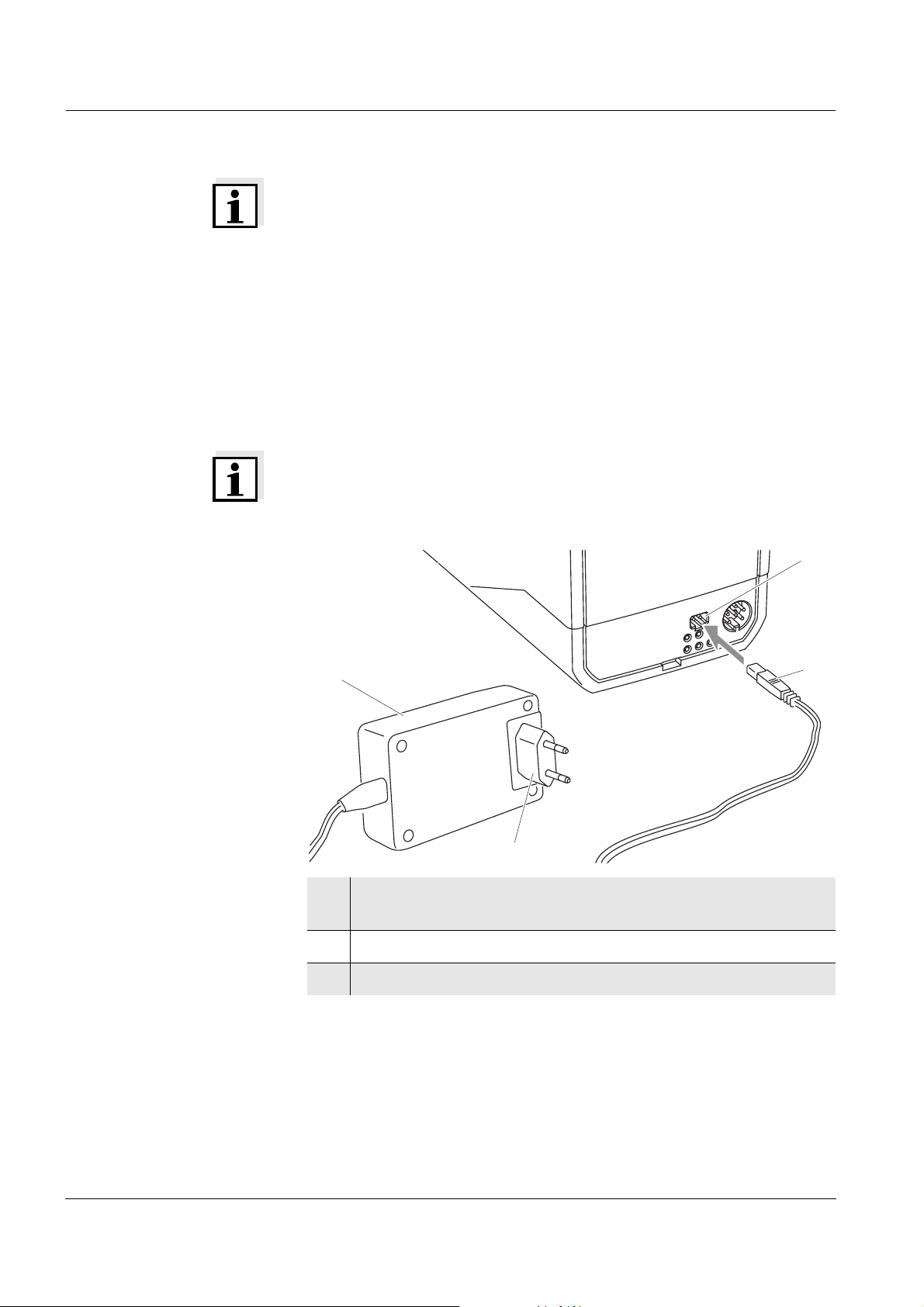
Connecting the power
pack
(optional)
2
4
3
14
1
1 If necessary, replace the Euro plug (1) on the power pack (2)
by the country-specific plug suitable for your country.
2 Connect the plug (3) to the socket (4) of the turbidimeter.
3 Connect the power pack to an easily accessible power socket.
ba75507e03 07/2006
Page 15
Turb 430 IR/T Commissioning
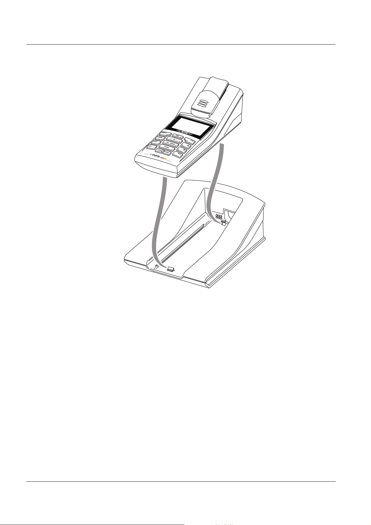
3.3 Connecting the LabStation
Note
The LabStation is available as an accessory (see section 8.1).
In order to use the functions of the LabStation for operation in the
laboratory, connect the LabStation and place the Turb 430 IR/T in the
LabStation.
Connecting the
LabStation (optional)
5
4
2
3
1
1 If necessary, replace the Euro plug (1) on the power pack (2)
by the country-specific plug suitable for your country.
2 Connect the plug (3) to the socket (4) of the LabStation.
3 Connect a PC or printer to the socket (5) of the LabStation as
necessary.
4 Connect the power pack to an easily accessible power socket.
ba75507e03 07/2006
5 Place the Turb 430 IR/T in the LabStation.
15
Page 16
Commissioning Turb 430 IR/T
LabStation
16
ba75507e03 07/2006
Page 17

Turb 430 IR/T Commissioning
3.4 Initial commissioning
Perform the following activities:
! For
– accumulator operation: insert the accumulator pack (see
section 5.1.2)
– line power operation and charging the accumulator pack: connect
the power pack (see section 3.2)
– operation with LabStation: connect the LabStation and place the
Turb 430 IR/T in the LabStation (see section 3.3)
! Switch on the meter (see section 4.1)
! Set the language as necessary (see section 4.3.3)
! Set the date and time as necessary (see section 4.3.4)
Note
When you set the language, date and time according to the mentioned
sections of this operating manual you will quickly become familiar with
the simple operation of the Turb 430 IR/T.
ba75507e03 07/2006
17
Page 18

Commissioning Turb 430 IR/T
18
ba75507e03 07/2006
Page 19
Turb 430 IR/T Operation
4 Operation
4.1 Switching on the meter
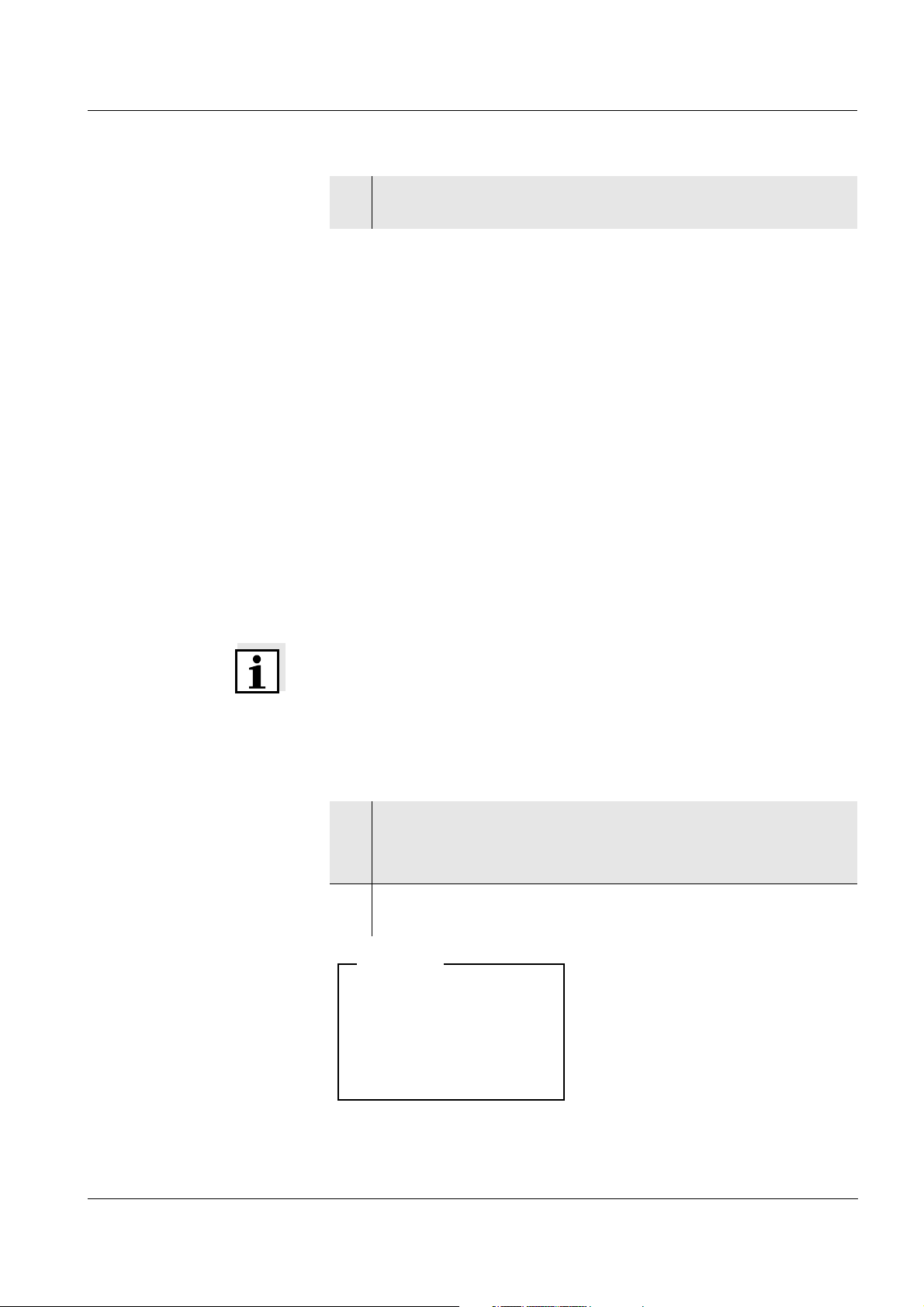
Switching on Press the <ON/OFF> key.
The Start menu appears for 30 seconds.
The status line indicates the meter designation and the version number
of the software.
Start
Turbidity
i Turb 430 IR V 0.24
Switching off Press the <ON/OFF> key.
Automatic switchoff
function
Note
in das Menü Start gelangen Sie bei eingeschaltetem Gerät durch ggf.
mehrfaches Drücken der Taste <ESC>.
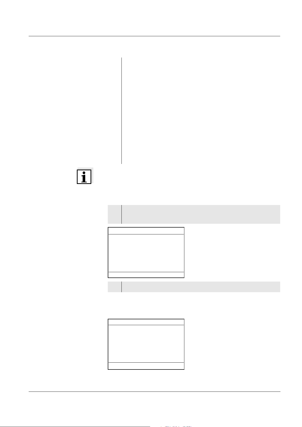
After a few seconds the meter automatically switches to the measuring
mode.
Turbidity
i Insert sample
i Press and hold <START>
i Align sample
The meter has an automatic switch-off function in order to save the
batteries or accumulator pack (see section 4.4). The automatic
switchoff switches off the meter if no key is pressed for an adjustable
period.
ba75507e03 07/2006
The automatic switchoff is not active
! if the power is supplied by the power pack (optional),
! if the power is supplied by the LabStation (optional),
! if the Timer function is running.
19
Page 20
Operation Turb 430 IR/T
Display illumination
with battery-powered
operation
During operation with batteries or accumulator pack the meter
automatically switches off the display illumination if no key is pressed
for 30 seconds. The illumination is switched on again with the next
keystroke.
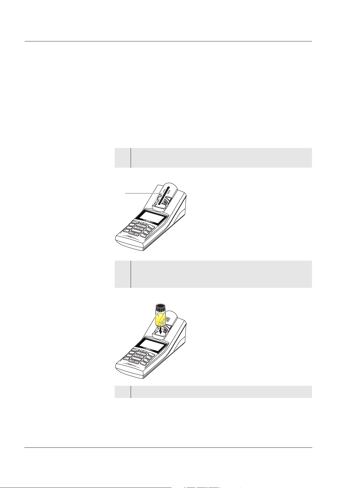
4.2 Inserting a cell
To be able to insert cells in the Turb 430 IR/T, the cell shaft has to be
prepared to take in a cell.
1 Push the dust cover (1) upward.
The cell shaft for 28 mm cells is open.
1
Inserting a 28 mm cell
2 Insert the cell so that it is positioned on the bottom of the cell
shaft.
The cell is ready to be measured.
3 Align the cell (see section 4.5.2).
20
ba75507e03 07/2006
Page 21

Turb 430 IR/T Operation
4.3 General operating principles
This section contains basic information on the operation of the
Turb 430 IR/T.
Operating elements,
display
Operating modes,
navigation
An overview of the operating elements and the display is given in
section 1.2 and section 1.3.
An overview of the operating modes of the Turb 430 IR/T and the
navigation through menus and functions can be found in section 4.3.1
and section 4.3.2.
4.3.1 Operating modes
The instrument has the following operating modes:
! Measurement
The display indicates measurement data in the measured value
display
! Calibration
The display indicates a calibration procedure with calibration
information
! Data transmission
The meter transmits measuring datasets or calibration records to the
serial interface
! Configuration
The display indicates a menu with further menus, settings and
functions
4.3.2 Navigation
Measured value display In the measured value display, open the menu with <MENU>.
Menus and dialogs The menus for settings and dialogs in courses contain further
submenus. The selection is made with the <▲><▼> keys.
The current selection is displayed in reverse video.
! Menus
The name of the menu is displayed at the upper edge of the frame.
Menus are opened by confirming with <START/ENTER>. Example:
ba75507e03 07/2006
21
Page 22

Operation Turb 430 IR/T
Configuration
Turbidity
System
Info
! Settings
Settings are indicated by a colon. The current setting is displayed on
the right-hand side. With <START/ENTER>, the selection of the
possible settings is opened. Subsequently, the setting can be
changed with <▲><▼> and<START/ENTER>.
Example:
System
Language: Deutsch
Beep:
Illumination
Contrast:
Temperature unit
Switchoff time
: On
:
:
Off
48 %
°C
30 min
! Functions
Functions are designated by the name of the function. They are
immediately carried out by confirming with <START/ENTER>.
Example: display the Calibration record function
(in the Turbidity menu).
Turbidity
Calibration record
Calibration interval:
Reset
:
i 2.00 4.01 7.00 10.01
090 d
! Messages
Information or operating instructions are designated by the i
symbol. They cannot be selected.
Example:
22
ba75507e03 07/2006
Page 23
Turb 430 IR/T Operation
Turbidity \ Calibration
i Insert standard
1000 FNU/NTU
i Press and hold <START>
i Align sample
The i indicates
info texts, e.g.
messages, notes or
instructions
Note
The principles of navigation are explained in the two following sections
by reference of examples:
! Setting the language (section 4.3.3)
! Setting the date and time (section 4.3.4).
ba75507e03 07/2006
23
Page 24
Operation Turb 430 IR/T
4.3.3 Navigation example 1: setting the language
Note
The following example describes in the language of the country how to
set the language. On delivery, English is set as the language in the
Turb 430 IR/T. During initial commissioning, the language is set in the
menu, Configuration / System / Language.
1 In the measured value display:
Open the Configuration menu with <MENU>.
The instrument is in the configuration mode.
2 Select the System menu with <▲><▼>.
The current selection is displayed in reverse video.
3 Open the System menu with <START/ENTER>.
4 Select the Language menu with <▲><▼>.
The current selection is displayed in reverse video.
System
Language: Deutsch
Store
Display
Reset
Interface
Continue ...
5 Open the setting of the Language with <START/ENTER>.
System
Language:
Store
Display
Reset
Interface
Continue ...
Deutsch
6 Select the required language with <▲><▼>.
24
7 Confirm the setting with <START/ENTER>.
The setting is active. The menu is displayed in the selected
language.
ba75507e03 07/2006
Page 25
Turb 430 IR/T Operation
8 To make further settings, switch to the next higher menu level
with <ESC>.
4.3.4 Navigation example 2: setting the date and time
The meter has a clock with a date function. The date and time are
indicated in the status line of the measured value display. When storing
measured values and calibrating, the current date and time are
automatically stored as well.
Numerals are generally entered via the number keys.
The correct setting of the date and time and date format is important for
the following functions and displays:
! Current date and time
Setting the date, time
and date format
! Calibration date
! Identification of stored measured values.
Therefore, check the time at regular intervals.
Note
After a fall of the supply voltage (empty batteries or accumulator pack),
the date and time are reset to 01.01.2003, 00:00 hours.
The data format can be switched from the display of day, month, year
(dd.mm.yy) to the display of month, day, year (mm/dd/yy or mm.dd.yy).
1 In the measured value display:
Open the Configuration menu with <MENU>.
The instrument is in the configuration mode.
2 Select and confirm the System / Continue ... / Date/time menu
with <▲><▼> and <START/ENTER>.
Date/time
Time:
:
Date
Date format
: dd.mm.yy
14:53:40
30.10.03
ba75507e03 07/2006
25
Page 26

Operation Turb 430 IR/T
3 Select and confirm the Time menu with <▲><▼> and
<START/ENTER>.
A display for the entry of numerals with the number keys opens
up.
Time
14:53:40
4 Enter the time using the number keys.
The digit to be changed is displayed underlined.
Note
In the case of wrong entries, you can cancel the procedure with <ESC>.
After canceling with <ESC>, it is possible to enter all digits once again.
The new digits are only taken over by confirming with <START/
ENTER>.
5 Confirm the setting with <START/ENTER>.
The time is set.
6 Set the current Date as necessary. The setting is made
similarly to that of the time.
7 Change the date format as necessary.
8 To make further settings, switch to the next higher menu level
with <ESC>.
or
Switch to the measured value display with <M> (short
pressure).
The instrument is in the measurement mode.
26
4.3.5 Menu overview
Turbidity Calibration record
Calibration interval
Reset
Timer
ba75507e03 07/2006
Page 27

Turb 430 IR/T Operation
System Language Deutsch
English
Français
Español
Measured value
Display
memory
RS232 download
Data filter Filter
ID
Date
Delete
i 4 of 1000 occupied
i Filter: No filter
Display Illumination Auto off
On
Off
Contrast 0 ... 100 %
Brightness 0 ... 100 %
Reset
Interface Baud rate 1200, 2400, 4800,
9600, 19200
Info
ba75507e03 07/2006
Continue ... /
Date/time
Continue ... /
Switchoff time
Continue ... /
Beep
Output format ASCII
CSV
Time hh:mm:ss
Date
Date format dd.mm.yy
mm.dd.yy
mm/dd/yy
10, 20, 30, 40, 50 min,
1, 2, 3, 4, 5, 10, 15, 20, 24 h
On
Off
27
Page 28

Operation Turb 430 IR/T
4.4 System settings (System menu)
The following instrument features and general functions can be found
in the Configuration / System menu:
! Language selection (Language)
! Memory and database functions (Store)
! Display settings (Display)
! Restore basic settings (Reset)
! Configuration of the interface for PC/printer (Interface)
! Setting the date/time (Date/time)
! Setting the switch-off time (Switchoff time)
! Setting the keyboard sound (Beep)
Settings/functions The settings are given in the menu, Configuration / System.
Move to the Configuration menu with the <MENU> key.
Menu item Setting Description
Language Deutsch
English
Select the language (see
section 4.3.3)
Français
Español
Store Display
RS232
download
Memory and database
functions
(see section 4.6.2)
Data filter
Delete
Display Illumination
Contrast
Brightness
Switch on/off the display
illumination (see
section 4.4.2)
Reset - Resets all system settings
to default
(see section 4.8.1)
Interface Baud rate
Output format
Baud rate of the data
interface
(see section 4.4.3)
28
Continue ... /
Date/time
Time
Date
Date format
Settings of time and date
(see section 4.3.4)
ba75507e03 07/2006
Page 29

Turb 430 IR/T Operation
Menu item Setting Description
Continue ... /
Switchoff time
10, 20, 30, 40,
50 min,
1, 2, 3, 4, 5, 10,
15, 20, 24 h
The automatic switchoff
function switches the
meter off if no entry is
made for a specified
period of time (Switchoff
time). This saves the
batteries or accumulator
pack.
Continue ... /
Beep
On
Off
Switch on/off the beep on
keystroke
4.4.1 Measured value memory
In the Measured value memory menu, you find functions to display and
edit the stored measurement datasets:
! Display the measurement datsets on the screen (Display)
! Download the measurement datsets to the RS232 interface (RS232
download)
! Set up filter rules for the stored measurement datsets (Data filter)
! Erase all stored measurement datsets (Delete)
! Information on the number of occupied memory locations
The settings are given in the menu, Configuration / System / Measured
value memory.
Move to the Configuration menu with the <MENU> key.
ba75507e03 07/2006
29
Page 30

Operation Turb 430 IR/T
Settings/functions
Menu item Setting/
Description
function
Display - Displays in pages all
measurement datasets that
correspond to the filter
settings.
Further options:
! Scroll through the
datasets with <▲><▼>.
! Output the displayed
dataset to the interface
with <PRT>.
! Quit the display with
<ESC>.
RS232 download - Downloads to the interface all
measurement datasets that
correspond to the filter
settings. The download is
ordered according to the date
and time.
The process can take several
minutes. To terminate the
process prematurely, press
<ESC>.
Data filter see
section 4.6.2.
Allows to set filter criteria in
order to display and
download datasets to the
interface.
Delete - Erases the entire contents of
the measuring data memory,
independent of the filter
settings.
Note:
All calibration data remains
stored when performing this
action.
All details on the subjects of memory and stored data is given in
section 4.6.2.
30
ba75507e03 07/2006
Page 31

Turb 430 IR/T Operation
4.4.2 Display
In the Configuration / System / Display menu, you set the display
features:
! Switching on/off the display illumination (Illumination)
! Display contrast (Contrast)
The settings are given in the menu, Configuration / System / Display.
Move to the Configuration menu with the <MENU> key.
Settings
Menu item Setting Description
Illumination Auto off The display illumination is
automatically switched off if
no key has been pressed
for 30 seconds.
On
Off
Switches the display
illumination on or off
permanently
Contrast 0 ... 100 % Changes the display
contrast
Brightness 0 ... 100 % Changes the display
brightness
4.4.3 Interface
In the Interface menu, you set the features of the interface:
! Transmission speed (Baud rate)
Settings
ba75507e03 07/2006
! Output format (Output format)
The settings are given in the menu, Configuration / System / Interface.
Move to the Configuration menu with the <MENU> key.
Menu item Setting Description
Baud rate 1200, 2400,
4800, 9600,
Baud rate of the data
interface
19200
Output format ASCII
CSV
Output format for data
transmission
For details, see section 4.7
31
Page 32

Operation Turb 430 IR/T
4.4.4 Date/time
In the Configuration / System / Continue ... / Date/time menu, you set
the system clock:
! Current time (Time)
! Current date (Date)
! Format of the date display (Date format)
The settings are given in the menu, Configuration / System / Continue
... / Date/time.
Move to the Configuration menu with the <MENU> key.
Settings
Menu item Setting Description
Time hh:mm:ss Enter the time with the
number keys
Date Enter the date with the
number keys
Date format dd.mm.yy
Settings of time and date.
mm.dd.yy
mm/dd/yy
32
ba75507e03 07/2006
Page 33

Turb 430 IR/T Operation
4.5 Turbidity
4.5.1 General information
Venting the sample Air bubbles in the sample affect the measuring result to a massive
extent because they have a large scattering effect on the incident light.
Larger air bubbles cause sudden changes in the measured values
whereas smaller air bubbles are recorded by the instrument as
turbidity. Therefore, avoid or remove air bubbles:
Avoiding or removing
air bubbles
Aligning the cell
! During sampling, ensure all movement is kept to a minimum
! If necessary, vent the sample (ultrasonic baths, heating or adding a
surface-active substance to reduce the surface tension)
Note
For turbidity values under 1 FNU/NTU, follow the instructions given in
the appendix (see A
PPENDIX: TURBIDITY VALUES UNDER 1 FNU/NTU).
4.5.2 Aligning and marking a cell
Even perfectly clean quality cells exhibit tiny directional differences in
their light transmittance. Therefore, if you want to achieve accurate and
reproducible measurement results, it is necessary to always index the
sample cells and cells for calibration standards in the same way (see
section 2130 of "Standard Methods for the Examination of Water and
Wastewater", 19th edition).
To do so, the optimum alignment of the cell is determined.
1 Clean the cell (see section 5.2.2).
ba75507e03 07/2006
2 Insert the cell (see section 4.2).
3 Align the cell:
! Press and hold the <START/ENTER> key.
! Slowly and in small steps rotate the cell by one complete
rotation (by 360 °).
After each step wait for a short time until the displayed
measured value is stable.
! Turn the cell back to the position with the lowest measured
value.
Note
To keep the drift as low as possible, the time for aligning the cell while
pressing and holding the <START/ENTER> key is limited to 30
seconds. After this time, the meter starts measuring automatically.
33
Page 34

Operation Turb 430 IR/T
4 Release the <START/ENTER> key.
Measurement starts. The measured value is displayed.
Marking a cell To be able to quickly bring a cell into the optimum position, it is helpful
to mark the optimum position of the cell once it is determined. This
shortens each measurement or calibration procedure with this cell
considerably.
The marking can, e. g., be done on a label on the cap of the cell.
5 Mark the optimum position of the cell.
The cell is prepared for the shortened measuring and
calibration procedures.
Measuring
4.5.3 Measuring turbidity
Caution
Never pour any liquids directly into the cell shaft. Always use a
cell for measurement. The meter only measures precisely if the
cell is closed with the black light protection cap (WTW cells).
Note
The outside of the cell always has to be clean, dry, and free of
fingerprints and scratches. Clean the cells before starting to measure
(see section 5.2.2). Only hold the cells by the top or by the black light
protection cap.
1 Rinse out a clean cell with the sample to be measured:
Pour approximately 10 ml sample into the cell. Close the cell
and rotate it several times before throwing the sample away.
2 Repeat the rinsing procedure twice more.
3 Fill the cell with the sample to be measured (approx. 15 ml).
Close the cell with the black light protection cap.
4 Clean the cell (see section 5.2.2).
34
5 Insert the cell (see section 4.2).
ba75507e03 07/2006
Page 35
Turb 430 IR/T Operation
6 Align the cell:
! Marked cell
– Align the marking on the cell cap with the marking on the
cell shaft.
– Press and for a short time hold the <START/ENTER>
key until the measured value is displayed.
! Unmarked cell (see page 33)
– Press and hold the <START/ENTER> key.
– Slowly and in small steps rotate the cell by one complete
rotation (by 360 °). After each step wait for a short time
until the displayed measured value is stable.
– Turn the cell back to the position with the lowest
measured value.
Note
To keep the drift as low as possible, the time for aligning the cell while
pressing and holding the <START/ENTER> key is limited to 30
seconds. After this time, the meter automatically starts measuring or
calibrating.
Display with measuring
range overflow
7 Release the <START/ENTER> key.
Measurement starts. The measured value is displayed.
Turbidity
157.0
8 Repeat the steps 2 to 8 for further samples.
If the measured value is outside the measuring range of the
Turb 430 IR/T, it is indicated on the display:
Turbidity
> 1100
FNU
NTU
01.02.05 15:12
FNU
NTU
ba75507e03 07/2006
01.02.05 15:12
35
Page 36

Operation Turb 430 IR/T
4.5.4 Settings for turbidity measurements
Overview For turbidity measurements, the following settings are possible in the
menu, Configuration / Turbidity:
! Calibration record (display, print)
! Entering the Calibration interval
! Reset
Settings/functions The settings are given in the menu, Configuration / Turbidity.
Move to the Configuration menu with the <MENU> key.
Menu item Possible
setting
Calibration record - Displays the calibration
Calibration interval 1 ... 999 d Calibration interval for
Reset Reset all settings for the
4.5.5 Calibration
When to calibrate? ! After the calibration interval has expired
! With a temperature change
Description
record of the last
calibration.
turbidity measurement (in
days).
If the calibration interval
has expired, the meter
reminds you to calibrate
before each measurement.
Turbidity measuring mode
(see section 4.8.2)
Calibration procedures
and calibration
standards
36
For the menu-guided three-point calibration you need the following
three calibration standards in the mentioned order:
Standard no. FNU/NTU
1 1000
2 10,0
30,02
ba75507e03 07/2006
Page 37
Turb 430 IR/T Operation
Calibration record At the end of each calibration procedure a calibration info (i symbol)
and the calibration record is displayed.
Displaying and
downloading calibration
data to interface
Sample printout of a
record
Preparing the
calibration
You can view the data of the last calibration on the display.
Subsequently, you can download the displayed calibration data to the
interface, e. g. to a printer or PC, with the <PRT> key.
The calibration record of the last calibration can be found under the
menu item, Configuration / Turbidity / Calibration record.
31.10.03 16:13
Turb 430 IR Ser. no. 12345678
Calibration Turbidity
Calibration date 31.10.03 16:13:33
Calibration interval 90 d
Perform the following preparatory activities when you want to calibrate:
1 Keep the cells with the required calibration standards ready
and mark them as necessary (see page 33).
2 Clean the cell (see section 5.2.2).
3 Insert the cell (see section 4.2).
Carrying out calibration
Note
For turbidity values under 1 FNU/NTU, follow the instructions given in
the appendix (see A
PPENDIX: TURBIDITY VALUES UNDER 1 FNU/NTU).
1 Press the <CAL/ZERO> key.
The menu-guided calibration begins.
Follow the instructions on the display.
Turbidity \ Calibration
i Insert standard
1000 FNU/NTU
i Press and hold <START>
i Align sample
2 Insert the cell with the displayed calibration standard (here e.g.
1000 FNU/NTU) in the cell shaft (see section 4.2).
ba75507e03 07/2006
37
Page 38
Operation Turb 430 IR/T
3 Align the cell:
! Marked cell:
– Align the marking on the cell cap with the marking on the
cell shaft.
– Press and hold the <START/ENTER> key until the
measured value is displayed.
! Unmarked cell (see page 33)
– Press and hold the <START/ENTER> key.
– Slowly and in small steps turn the cell by one complete
rotation (by 360 °).
– After each step wait for a short time until the displayed
measured value is stable.
– Turn the cell back to the position with the lowest
measured value.
Turbidity \ Calibration
i Turb. = 1000 FNU/NTU
i Start calibration
by releasing <START>
4 Release the <START/ENTER> key.
Measurement of the calibration standard begins.
Note
Before measuring the third calibration standard of 0.02 FNU/NTU you
can exit the calibration with <ESC> at any time.
The new calibration data is discarded. The old calibration data is further
used.
5 Repeat the steps 4 - 6 with the calibration standards, 10.0 FNU/
NTU and 0.02 FNU/NTU.
After measuring the 0.02 FNU/NTU calibration standard, the
calibration result is displayed.
Calibration is completed.
38
6 Confirm the calibration result with <START/ENTER>.
The calibration record is displayed.
7 Confirm the calibration record with <START/ENTER>.
The display shows instructions for the first measurement.
ba75507e03 07/2006
Page 39

Turb 430 IR/T Operation
Turbidity
i Insert sample
i Press and hold <START>
i Align sample
Note
If i Calibration error! was displayed as the calibration result, a note
appears on the display to recalibrate before measuring.
Should a valid calibration not be possible the meter also offers to
continue measuring with the last valid calibration data.
ba75507e03 07/2006
39
Page 40

Operation Turb 430 IR/T
4.6 Saving
The meter has 1000 memory locations for measurement datsets.
You can transmit measured values (datasets) to the data memory with
the <STO> key.
Each storage process transmits the current dataset to the interface at
the same time.
The number of memory locations that are still free is displayed in the
Store menu. The number of memory locations that are occupied is
displayed in the System Measured value memory menu.
Measurement dataset A complete dataset consists of:
! Date/time
! ID number (ID)
! Measured value
4.6.1 Storing measurement datsets
Proceed as follows to transmit to the data memory and simultaneously
output to the interface a measurement dataset:
1 Press the <STO> key.
The Store display appears.
Store (996 free)
i 02.02.2005 11:24:16
16.80 FNU/NTU
ID:
Store (ID: 1)
1
2 Using <▲><▼>, <START/ENTER> and the number keys,
change and confirm the ID number (ID) as necessary (0 ...
999).
3Using <START/ENTER> or <STO>, confirm Store.
The dataset is stored. The instrument switches to the
measured value display.
40
Note
A measurement dataset is stored quickly by twice pressing <STO>. It
is stored with the ID last set.
ba75507e03 07/2006
Page 41

Turb 430 IR/T Operation
If the memory is full You can erase the entire memory (see section 4.6.5), or overwrite the
oldest dataset with the next storing procedure.
A security prompt appears before a dataset is overwritten.
4.6.2 Filtering measurement datsets
The functions to display and download stored measurement datsets
(see section 4.4.1) refer to all stored measurement datsets that
correspond to the specified filter criteria.
The settings are given in the menu, Configuration / System / Measured
value memory / Data filter.
Move to the Configuration menu with the <MENU> key.
Data filter
Menu item Setting/function Description
Filter Filter criteria:
No filter Data filter switched off
ID Selection according to ID
number
Date Selection according to
period
ID + Date Selection according to
period and ID number
ID Entry of filter criteria
These menu items are
made visible by selecting
Date
the filter criteria in the Filter
menu.
ba75507e03 07/2006
41
Page 42

Operation Turb 430 IR/T
4.6.3 Displaying measurement datsets
You can read out stored datasets to the display. Only those datasets
are displayed that correspond to the selected filter criteria (see
section 4.6.2).
Start reading out the data to the display in the menu, Configuration /
System / Measured value memory / Display.
Representation of a
dataset
02.02.2005 11:24:16
ID: 1
16.80 FNU/NTU
i Scroll with
▲ ▼
Further datasets that correspond to the filter criteria are displayed with
the <▲><▼> keys.
Quitting the display To quit the display of stored measurement datasets, you have the
following options:
! Switch directly to the measured value display with <M> (short
pressure).
! Leave the display and switch to the superordinate menu with <ESC>
or <START/ENTER>.
4.6.4 Download the measurement datsets to the RS232 interface
42
You can download stored datasets to the RS232 interface. Only those
datasets are downloaded that correspond to the selected filter criteria
(see section 4.6.2).
The datasets are downloaded in the specified output format (see
section 4.7.3).
The data download to the interface is started in the menu,
Configuration / System / Measured value memory / RS232 download.
ba75507e03 07/2006
Page 43

Turb 430 IR/T Operation
4.6.5 Erasing stored measurement datasets
You can erase the stored measurement datsets altogether if you do no
longer need them.
Erasing all measurement datsets is done in the menu, Configuration /
System / Measured value memory / Delete.
Note
Erasing individual datasets is not possible. If all memory locations are
occupied, however, it is possible to overwrite the oldest dataset at a
time. A security prompt appears before a dataset is overwritten.
4.7 Transmitting data (RS 232 interface)
Via the RS 232 interface, you can transmit data to a PC or an external
printer.
The data can be transmitted to a PC, for example, with the aid of a socalled terminal program.
Generally, a terminal program serves to establish a connection to a
device on a data interface and to communicate with the device via a
console on the display. A terminal program usually offers the possibility
to save the contents of the console in a text file or print it. If the terminal
program is connected to the meter, it can receive data from the meter
and display it on the console.
Terminal programs are available for different operating systems by
different manufacturers. Windows (version 95 to XP) contains the
"HyperTerminal" terminal program. It is in the program menu under
Accessories.
For more detailed information please refer to the user information of the
terminal program.
The settings required for the use of the "HyperTerminal" program are
given in section 4.7.1.
Note
When using the "HyperTerminal" program you can load the
transmission data automatically using the *.ht file provided on the CD.
ba75507e03 07/2006
43
Page 44

Operation Turb 430 IR/T
4.7.1 Connecting a PC/external printer
Connect the interface to the devices via the AK540/B (PC) or AK540/S
(external printer) cable.
Caution
The RS232 interface is not galvanically isolated. When connecting
an earthed PC/printer, measurements cannot be performed in
earthed media as incorrect values would result.
Set up the following transmission data on the PC/printer:
Baud rate can be selected from: 1200, 2400, 4800, 9600,
19200
The baud rate must agree with the baud rate set on
the PC/printer.
Handshake RTS/CTS
Socket assignment
PC only:
Parity none
Data bits 8
Stop bits 1s
3
4
6
1
5
1 RTS
2 RxD
2
3 TxD
4 DTR
5 SG
RS 232
REC
6 CTS
4.7.2 Configuring the RS232 interface
For error-free data transmission, the RS232 interface should be set to
the same transmission speed (Baud rate) on the Turb 430 IR/T and
PC/printer.
44
You can set the following values for the baud rate on the Turb 430 IR/
T: 1200, 2400, 4800, 9600, 19200.
The baud rate is selected in the menu, Configuration / System /
Interface / Baud rate.
ba75507e03 07/2006
Page 45

Turb 430 IR/T Operation
4.7.3 Selecting the output format of datasets
For downloading data to the interface you can select the output format.
It is selected in the menu, Configuration / System / Interface / Output
format.
The ASCII output format delivers formatted datasets.
The CSV output format delivers datasets separated by ";".
Output format, ASCII
Turb 430 IR Ser. no. 12345678
31.10.04 09:56:20
ID: 1
16.01 FNU/NTU
________________________________________
Turb 430 IR Ser. no. 12345678
31.10.04 15:48:08
ID: 1
26.01 FNU/NTU
________________________________________
etc...
ba75507e03 07/2006
45
Page 46

Operation Turb 430 IR/T
Output format, CSV
123456
15.01.05;15:06:49;1;26.5;FNU/NTU;VALID;
15.01.05;16:06:49;1;16.5;FNU/NTU;VALID;
Data Description
1 Date Date of storing
2 Time Time of storing
3 ID adjusted ID
4 Measured value ! Measured value or
! Upper/lower measuring range limit
(only with measured value status, OFL/
UFL)
5 Unit of 4 ! Unit of the measured value
6 Measured value
status of 4
! VALID: Measured value valid
! INVALID: Measured value invalid
! UFL: Measured value below the lower
measuring range limit
! OFL: Measured value above the upper
measuring range limit
46
ba75507e03 07/2006
Page 47

Turb 430 IR/T Operation
4.7.4 Transmitting data
The following table shows which data are transmitted to the interface in
which way:
Data Operation / description
Current
measured value
! Press <PRT>.
! Simultaneously with every manual storage
process.
Stored measured
values
! Display stored dataset and press <PRT>.
! All datasets according to the filter criteria via
the RS232 download function
(see section 4.6.2).
Note
With the <PRT> key you output data that is being shown on the display
to the interface (displayed measured values, stored measurement
datsets, calibration record).
ba75507e03 07/2006
47
Page 48

Operation Turb 430 IR/T
4.8 Reset
You can reset (initialize) all system and measurement settings.
4.8.1 Resetting the system settings
With the System / Reset function, all resettable settings are reset.
! Settings for Turbidity (see section 4.8.2)
! System settings
System setting Default settings
Baud rate 4800 Baud
Output format ASCII
Illumination Auto off
Contrast 50 %
Brightness 50 %
Switchoff time 30 min
Beep On
4.8.2 Resetting turbidimeter settings
With the Turbidity / Reset function, all turbidimeter settings are reset.
Setting Default settings
Calibration interval 90 d
48
ba75507e03 07/2006
Page 49

Turb 430 IR/T Operation
4.9 Meter information
The following meter information is listed in the Configuration / Info
menu:
! Model designation
! Software version
! Series number of the meter
Info
i Model: Turb 430 IR
i Software: V 0.35
i Ser. no.
: 04280003
4.10 Software update
With a software update you obtain the current instrument software (see
appendix).
The current software version can be found on the Internet under
www.WTW.com.
The proceeding for updating the software is given in the appendix (see
A
PPENDIX: FIRMWARE UPDATE).
ba75507e03 07/2006
49
Page 50

Operation Turb 430 IR/T
50
ba75507e03 07/2006
Page 51
Turb 430 IR/T Maintenance, cleaning, disposal
5 Maintenance, cleaning, disposal
5.1 Maintenance
The meter is almost maintenance-free.
The only maintenance task is replacing the batteries or accumulator
pack.
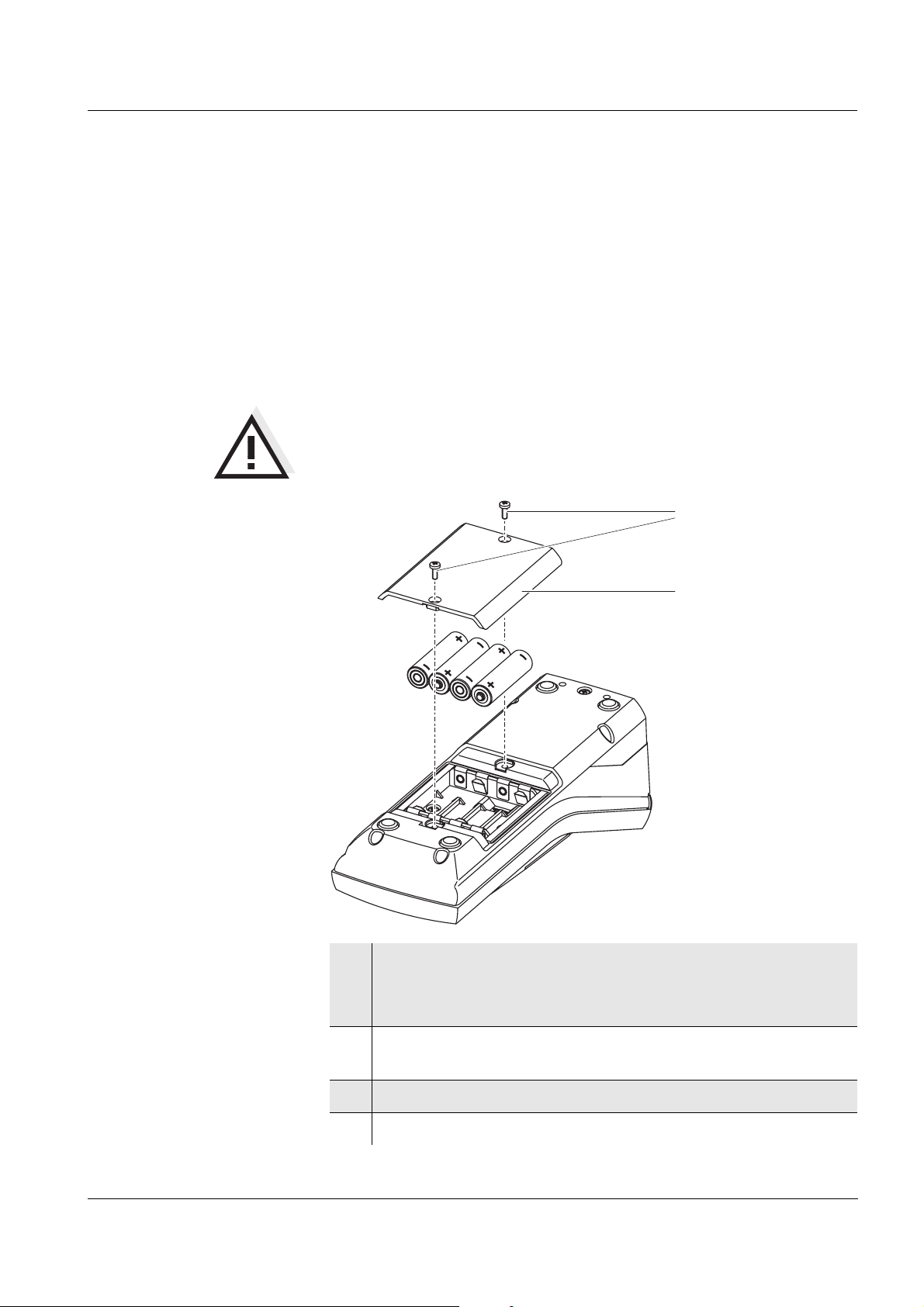
5.1.1 Inserting/exchanging the batteries
Caution
Make sure that the poles of the batteries are the right way round.
The ± signs on the batteries must correspond to the ± signs in the
battery compartment.
1
2
1 Open the battery compartment:
– Unscrew the two screws (1) on the underside of the meter,
– Remove the lid of the battery compartment (2).
ba75507e03 07/2006
2 If necessary, take four old batteries out of the battery
compartment.
3 Insert four batteries (3) in the battery compartment.
4 Close the battery compartment and fix it with the screws.
51
Page 52
Maintenance, cleaning, disposal Turb 430 IR/T
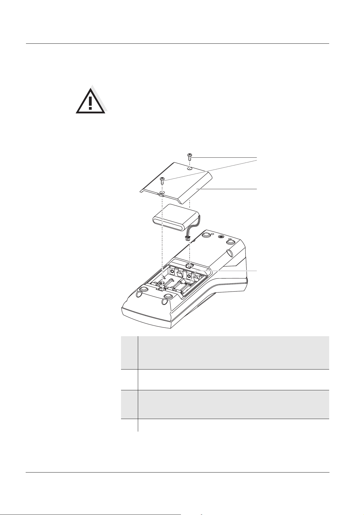
5.1.2 Retrofitting the accumulator pack
Caution
Use original WTW accumulator packs only.
Together with the power pack the accumulator pack is available as an
accessory (see section 8.1).
1
2
3
1 Open the battery compartment:
– Unscrew the two screws (1) on the underside of the meter,
– Remove the lid of the battery compartment (2).
2 If necessary, take four old batteries out of the battery
compartment.
3 Connect the cable of the accumulator pack with the socket (3)
on the bottom of the battery compartment and insert the
accumulator pack in the battery compartment.
4 Close the battery compartment and fix it with the screws.
52
ba75507e03 07/2006
Page 53
Turb 430 IR/T Maintenance, cleaning, disposal
5.2 Cleaning
Occasionally wipe the outside of the meter with a damp, lint-free cloth.
Disinfect the housing with isopropanol as required.
Caution
The housing components are made out of synthetic materials
(polyurethane, ABS and PMMA). Thus, avoid contact with acetone
and similar detergents that contain solvents. Remove any
splashes immediately.
5.2.1 Cleaning the cell shaft
If liquid is in the cell shaft (e.g. due to a spilled cell), clean the cell shaft
as follows:
1 Switch the Turb 430 IR/T off and pull out the power plug.
2 Rinse the cell shaft with distilled water.
5.2.2 Cleaning the cells
Cells have to be clean, dry, and free of fingerprints and scratches.
Therefore, clean them regularly:
1 Clean the cells inside and out with hydrochloric acid or
laboratory soap.
2 Rinse out several times with distilled water.
3 Let them dry in the air.
4 Only hold the cells by the top or by the light protection cap so
that the optical path is not impaired.
5 Before measuring, clean the cell with the enclosed cleaning
cloth.
Note
Scratches in the glass change the optical characteristics of the cell and
falsify the measured value. For this reason, never use scratched cells!
ba75507e03 07/2006
53
Page 54

Maintenance, cleaning, disposal Turb 430 IR/T
5.3 Disposal
Packing This meter is sent out in a protective transport packing.
We recommend: Keep the packing material. The original packing
protects the instrument against damage during transport.
Batteries/accumulator
pack
NiMH
Meter Dispose of the meter without the batteries and accumulator pack as
Remove the batteries or accumulator pack from the meter (see
section 5.1).
Dispose of the batteries or accumulator pack at a suitable facility
according to local legal requirements. It is illegal to dispose of the
accumulator pack with household refuse.
electronic waste at an appropriate collection point.
54
ba75507e03 07/2006
Page 55

Turb 430 IR/T What to do if...
6 What to do if...
6.1 General errors
Display, LoBat
Instrument does not
react to keystroke
Error message,
Error
0, 8, 16, 16384
Cause Remedy
– The batteries or accumulator
pack are largely depleted
Cause Remedy
– Software error
– Operating condition undefined
or EMC load unallowed
Cause Remedy
– Instrument error – Repeat measurement
– Insert new batteries
– Charge the accumulator pack
(see section 3.2)
– Processor reset:
Press the <START/ENTER>
and <PRT> key
simultaneously.
– Meter defective,
send meter to WTW for repair
and quote the error number
Error message,
Measured values
obviously incorrect
Measured value display
< 0.01 FNU
ba75507e03 07/2006
6.2 Turbidity
Cause Remedy
– Cell not correctly inserted – Lock cell into place
– Cell contaminated – Clean the cell
– Calibration too old – Carry out calibration
Cause Remedy
– Calibration defective – Carry out calibration
– Measured value outside the
measuring range
– not possible
55
Page 56

What to do if... Turb 430 IR/T
56
ba75507e03 07/2006
Page 57

Turb 430 IR/T Technical data
7 Technical data
7.1 General data
7.1.1 Turb 430 IR/T
Dimensions approx. 236 x 86 x 117 mm
Weight approx. 0.6 kg (without batteries)
Mechanical structure Type of protection IP 67
Electrical safety Protective class III
Test certificates cETLus, CE, FCC
Ambient
conditions
Allowable relative
humidity
Power
supply
Storage - 25 °C ... + 65 °C
Operation 0 °C ... + 50 °C
Climatic class 2
Yearly mean:
30 days /year:
other days:
Batteries 4 x 1.5 V, type AA
Operating time with
battery operation
Accumulator pack
(optional)
Power pack
Charging device
(optional)
75 %
95 %
85 %
Turb 430 IR: approx. 3000 measurements
Turb 430 T: approx. 2000 measurements
5 x 1.2 V nickel metal hydride (NiMH),
type AA
FRIWO FW7555M/09, 15.1432.500-00
Friwo Part. No. 1883259
Input: 100 ... 240 V ~ / 50 ... 60 Hz / 400 mA
Output: 9 V = / 1.5 A
Connection max. overvoltage category II
Primary plugs contained in the scope of
delivery: Euro, US, UK and Australian.
interface
ba75507e03 07/2006
Serial
Connection of the cable AK 540/B or AK 540/S
Baud rate adjustable:
1200, 2400, 4800, 9600, 19200 Baud
Type RS232
Data bits 8
Stop bits 2
Parity None
Handshake RTS/CTS
Cable length max. 15 m
57
Page 58

Technical data Turb 430 IR/T
Guidelines
and norms used
EMC EC guideline 89/336/EEC
EN 61326-1/A3:2003
FCC Class A
Instrument safety EC guideline 73/23/EEC
EN 61010-1 :2001
UL STD 61010-1
CAN/CSA-C22.2 No. 61010-1
Climatic class VDI/VDE 3540
IP protection EN 60529:1991
FCC Class A Equipment Statement
Note: This equipment has been tested and found to comply with
the limits for a Class A digital device, pursuant to Part 15 of the
FCC Rules. These limits are designed to provide reasonable
protection against harmful interference when the equipment is
operated in a commercial environment. This equipment
generates, uses, and can radiate radio frequency energy and, if
not installed and used in accordance with the instruction manual,
may cause harmful interference to radio communications.
Operation of this equipment in a residential area is likely to cause
harmful interference in which case the user will be required to
correct the interference at his own expense.
58
7.1.2 LabStation
Dimensions approx. 236 x 82 x 170 mm
Weight approx. 0.6 kg
ba75507e03 07/2006
Page 59

Turb 430 IR/T Technical data
7.2 Turbidity
7.2.1 Turb 430 IR
Measuring principle Nephelometric measurement according to DIN EN ISO 7027
Light source Infrared LED
Measuring range 0.01 ... 1100 FNU/NTU
Resolution in the range
0,01 ... 9,99
in the range
10,0 ... 99,9
in the range
100 ... 1100
max. 0.01 FNU/NTU
max. 0.1 FNU/NTU
max. 1 FNU/NTU
Accuracy in the range
0 ... 1100 FNU/NTU
± 2 % of the measured value
or ± 0.01 FNU/NTU
Reproducibility 0,5% of the measured value
Response time 4 seconds
Calibration Automatic 3-point calibration
7.2.2 Turb 430 T
Measuring principle Nephelometric measurement according to US EPA 180.1
Light source White light tungsten lamp
Measuring range 0.01 ... 1100 NTU
Resolution in the range
0,01 ... 9,99
max. 0.01 NTU
in the range
10,0 ... 99,9
max. 0.1 NTU
in the range
100 ... 1100
max. 1 NTU
Accuracy in the range
Reproducibility 1% of the measured value
Response time 7 seconds
Calibration Automatic 3-point calibration
ba75507e03 07/2006
0 ... 500 NTU
in the range
500 ... 1100 NTU
± 2 % of the measured value
or ± 0.01 NTU
± 3 % of the measured value
59
Page 60

Technical data Turb 430 IR/T
60
ba75507e03 07/2006
Page 61

Turb 430 IR/T Accessories, options
8 Accessories, options
8.1 WTW accessories
Description Model Order no.
LabStation pHotoFlex LS 251 301
Accumulator with Turb 430 IR/T
pHotoFlex BB 251 300
power pack
3 empty cuvettes, 28 x 60 mm LKS28-Set 251 302
Calibration standard kit for
Kal.Kit Turb 430 IR 600 560
Turb 430 IR
Calibration standard kit for
Kal.Kit Turb 430 T 600 561
Turb 430 T
Thermoprinter
Needle printer
* a connection cable is required to connect the printer (see
section 8.1.1)
*
*
P3001 250 045
LQ 300+ 250 046
8.1.1 Connection cable:
PC You can connect a PC (serial COM interface) to the Turb 430 IR/T as
follows:
ba75507e03 07/2006
Description Model Order no.
! Connection PC - Turb 430 IR/T
– Cable AK 540/B 902 842
+ USB adapter
Ada USB 902 881
(for USB connection on PC)
! Connection PC - LabStation
– Zero modem cable included in the scope of
delivery of the LabStation
+ USB adapter
Ada USB 902 881
(for USB connection on PC)
61
Page 62

Accessories, options Turb 430 IR/T
Thermoprinter
You can connect the P3001 to the Turb 430 IR/T in the following ways:
Description Model Order
no.
! Connection P3001 - Turb 430 IR/T
– Cable AK 540/S 902 843
! Connection P3001 - LabStation
– Cable AK 3000 250 745
in conjunction with an adapter
Specialist shops
(socket - socket) [GenderChanger]
or:
– Cable, 2 x 9-pin (socket - plug) Specialist shops
Needle printer You can connect an LQ300 needle printer to the Turb 430 IR/T in one
of the following ways:
Description Model Order
no.
! Connection LQ300 - Turb 430 IR/T
– Cable AK 540/B 902 842
with adapter
Specialist shops
9-pin (plug) - 25-pin (plug)
! Connection LQ300 - LabStation
– Cable AK/LQ300 250 746
in conjunction with an adapter
Specialist shops
(socket - socket) [GenderChanger]
or:
– Zero modem cable,
Specialist shops
9-pin (socket) - 25-pin (plug)
62
ba75507e03 07/2006
Page 63

Turb 430 IR/T Lists
9Lists
This chapter provides additional information and orientation aids.
Abbreviations The list of abbreviations explains the indicators and the abbreviations
that appear on the display and in the manual.
Specialist terms The glossary briefly explains the meaning of the specialist terms.
However, terms that should already be familiar to the target group are
not described here.
ba75507e03 07/2006
63
Page 64

Lists Turb 430 IR/T
Abbreviations
Cal Calibration
dDay
h Hour
j Year
LoBat Batteries almost empty (Low battery)
mMonth
s Second
S Slope (internat. k)
SELV Safety Extra Low Voltage
Slp. Slope determined with calibration
64
ba75507e03 07/2006
Page 65

Turb 430 IR/T Lists
Glossary
Adjusting To manipulate a measuring system so that the relevant value (e. g. the
displayed value) differs as little as possible from the correct value or a
value that is regarded as correct, or that the difference remains within
the tolerance.
Calibration Comparing the value from a measuring system (e. g. the displayed
value) to the correct value or a value that is regarded as correct. Often,
this expression is also used when the measuring system is adjusted at
the same time (see adjusting).
Cell Vessel that takes a liquid sample for measurement.
LED Light Emitting Diode
LEDs are used as the light source in the Turb 430 IR/T.
Measured parameter The measured parameter is the physical dimension determined by
measuring, e. g. pH, conductivity or DO concentration.
Measured value The measured value is the special value of a measured parameter to
be determined. It is given as a combination of the numerical value and
unit (e. g. 3 m; 0.5 s; 5.2 A; 373.15 K).
Measuring system The measuring system comprises all the devices used for measuring,
e. g. meter and sensor. In addition, there is the cable and possibly an
amplifier, terminal strip and armature.
Molality Molality is the quantity (in Mol) of a dissolved substance in 1000 g
solvent.
Reset Restoring the original condition of all settings of a measuring system.
Resolution Smallest difference between two measured values that can be
displayed by a meter.
Standard solution The standard solution is a solution where the measured value is
known by definition. It is used to calibrate a measuring system.
Test sample Designation of the test sample ready to be measured. Normally, a test
sample is made by processing the original sample. The test sample
and original sample are identical if the test sample was not processed.
ba75507e03 07/2006
65
Page 66

Lists Turb 430 IR/T
66
ba75507e03 07/2006
Page 67

Turb 430 IR/T Index
10 Index
A
Accumulator pack
Charging time
Air ..........................................................33
Aligning and marking a cell .......................33
Authorized use .........................................10
Automatic switchoff function ................14, 19
.....................................13
C
Calibration ...............................................36
Calibration order ......................................36
Calibration points and measuring ranges ...36
Calibration standards ...............................36
Cleaning .................................................53
Connecting a PC ......................................44
Connecting a printer .................................44
Connecting sensors ...................................7
D
Data filter ................................................41
Dataset ...................................................40
Date and time ....................................25, 32
Default settings
System settings
Turbidimeter .......................................48
Display ................................................7, 31
Display illumination ..............................7, 20
..................................48
F
Filter .......................................................41
Firmware update ......................................69
I
Initial commissioning ................................17
Initialization .............................................48
Inserting a cell .........................................20
Interface ..................................................31
J
Jack field ...................................................7
M
Measured value display ........................... 21
Measured value memory ......................... 40
Measurement dataset .............................. 40
Measuring range overflow ........................ 35
Measuring turbidity .................................. 34
Menus (navigation) .................................. 21
Messages ............................................... 22
N
Navigation .............................................. 21
O
Obligations of the purchaser ..................... 11
Operating modes .................................... 21
Operational safety ................................... 10
P
Power pack ............................................. 13
Print ....................................................... 47
R
Reset ..................................................... 48
RS232 socket assignment ....................... 44
S
Safe operation ........................................ 11
Safety ...................................................... 9
Saving .................................................... 40
Scope of delivery .................................... 13
Storage .................................................. 29
Switching on ........................................... 19
System settings ...................................... 28
T
Target group ............................................. 9
Transmitting data .................................... 43
Transmitting measured values .................. 43
Turbidity ................................................. 33
K
Keys .........................................................6
ba75507e03 07/2006
67
Page 68

Index Turb 430 IR/T
68
ba75507e03 07/2006
Page 69

Turb 430 IR/T
Appendix: Firmware update
General information With the "Firmware Update Turb430" program you can update the
firmware of the Turb 430 IR/T to the latest version with the aid of a
Personal Computer.
A free serial interface (COM port) on your PC and an interface cable is
required for this (see chapter 8 A
Program installation Install the firmware update program on your PC with the
"Turb430_Vx_yy_English.exe" installation program.
Program start Start the "Firmware Update Turb430" program from the WTW directory
in the Windows start menu. The program automatically selects the first
free serial interface (COM port). The selected interface is displayed on
the left side of the status line on the screen bottom.
Via the language menu you can change the adjusted language.
CCESSORIES, OPTIONS).
Firmware update Proceed as follows:
1 With the aid of an interface cable, connect the Turb 430 IR/T to
the serial interface (COM port) of the PC named in the status
line.
2 Make sure the Turb 430 IR/T is switched on.
3 To start the updating process click the OK button.
4 Then follow the instructions of the program.
A corresponding message and a progress bar (in %) appear
during the programming procedure.
The programming procedure takes approx. four minutes.
A final message appears after the successful programming
procedure. The firmware update is completed with this.
5 Disconnect the meter from the PC.
The instrument is ready for operation.
After switching the meter off and on again you can check on the start
display whether the meter has taken over the new software version.
ba75507e03 07/2006
69
Page 70

Turb 430 IR/T
Appendix: Turbidity values under 1 FNU/NTU
With turbidity values (under 1 FNU/NTU), the measured value is
strongly influenced by the cell and its alignment.
In order to increase measuring accuracy with turbidity values under 1
FNU/NTU, calibration in the 0.02 FNU/NTU standard and later
measurement should be carried out in the same cell. For calibration in
the standards 10.0 and 1000 FNU/NTU follow the instructions on the
display.
Proceed as follows to measure turbidity values under 1 FU/NTU:
Calibration procedure:
Measuring
1 Press the <CAL/ZERO> key.
The menu-guided calibration begins.
2 Carry out calibration of the standards 1000 FNU/NTU and
10.0 FNU/NTU in a clean and unscratched cell according to
the menu guidance.
3 Fill the cleaned cell with the 0.02 FNU/NTU standard and
calibrate.
4 Mark the alignment of the cell.
Calibrate
! after the calibration interval has expired
! with a temperature change
5 Fill the marked and cleaned cell with test sample, align it
with the marking and measure.
6 If necessary, fill the marked and cleaned cell once more
with test sample and carry out further measurements.
70
ba75507e03 07/2006
Page 71

Wissenschaftlich-Technische Werkstätten GmbH
Dr.-Karl-Slevogt-Straße 1
D-82362 Weilheim
Germany
Tel: +49 (0) 881 183-0
+49 (0) 881 183-100
Fax: +49 (0) 881 183-420
E-Mail: Info@WTW.com
Internet: http://www.WTW.com
 Loading...