

Page 1
OPERATIONS MANUAL
4010-3
ba76143e01 04/2013
MultiLab 4010-3
pH/ORP/D.O./Cond
DIGITAL METER FOR IDS SENSORS
Page 2

MultiLab 4010-3
For the most recent version of the manual, please visit www.ysi.com.
Contact YSI
1725 Brannum Lane
Yellow Springs, OH 45387 USA
Tel: +1 937-767-7241
800-765-4974
Email: environmental@ysi.com
Internet: www.ysi.com
Copyright © 2013 Xylem Inc.
2 ba76143e01 04/2013
Page 3

MultiLab 4010-3 Contents
MultiLab 4010-3 - Contents
1 Overview. . . . . . . . . . . . . . . . . . . . . . . . . . . . . . . . . . . . . . . . . . 7
1.1 Meter MultiLab 4010-3 . . . . . . . . . . . . . . . . . . . . . . . . . . . . . . . . 7
1.2 Sensors. . . . . . . . . . . . . . . . . . . . . . . . . . . . . . . . . . . . . . . . . . . . 8
1.2.1 IDS sensors . . . . . . . . . . . . . . . . . . . . . . . . . . . . . . . . . . . . 8
1.2.2 IDS adapter for analog pH sensors . . . . . . . . . . . . . . . . . . 9
1.2.3 Automatic sensor recognition . . . . . . . . . . . . . . . . . . . . . . 9
2 Safety . . . . . . . . . . . . . . . . . . . . . . . . . . . . . . . . . . . . . . . . . . . 10
2.1 Safety information . . . . . . . . . . . . . . . . . . . . . . . . . . . . . . . . . . . 10
2.1.1 Safety information in the operating manual . . . . . . . . . . . 10
2.1.2 Safety signs on the meter . . . . . . . . . . . . . . . . . . . . . . . . 10
2.1.3 Further documents providing safety information . . . . . . . 10
2.2 Safe operation. . . . . . . . . . . . . . . . . . . . . . . . . . . . . . . . . . . . . . 10
2.2.1 Authorized use. . . . . . . . . . . . . . . . . . . . . . . . . . . . . . . . . 10
2.2.2 Requirements for safe operation . . . . . . . . . . . . . . . . . . . 11
2.2.3 Unauthorized use. . . . . . . . . . . . . . . . . . . . . . . . . . . . . . . 11
3 Commissioning . . . . . . . . . . . . . . . . . . . . . . . . . . . . . . . . . . . 12
3.1 Scope of delivery . . . . . . . . . . . . . . . . . . . . . . . . . . . . . . . . . . . 12
3.2 Power supply . . . . . . . . . . . . . . . . . . . . . . . . . . . . . . . . . . . . . . 12
3.3 Initial commissioning . . . . . . . . . . . . . . . . . . . . . . . . . . . . . . . . . 12
3.3.1 Connecting the power pack . . . . . . . . . . . . . . . . . . . . . . . 13
4 Operation . . . . . . . . . . . . . . . . . . . . . . . . . . . . . . . . . . . . . . . . 14
4.1 General operating principles . . . . . . . . . . . . . . . . . . . . . . . . . . . 14
4.1.1 Keypad. . . . . . . . . . . . . . . . . . . . . . . . . . . . . . . . . . . . . . . 14
4.1.2 Display . . . . . . . . . . . . . . . . . . . . . . . . . . . . . . . . . . . . . . . 15
4.1.3 Status information . . . . . . . . . . . . . . . . . . . . . . . . . . . . . . 15
4.1.4 Instrument connectors . . . . . . . . . . . . . . . . . . . . . . . . . . . 16
4.1.5 Channel display . . . . . . . . . . . . . . . . . . . . . . . . . . . . . . . . 17
4.1.6 Sensor info. . . . . . . . . . . . . . . . . . . . . . . . . . . . . . . . . . . . 17
4.1.7 Display of several sensors in the measuring mode . . 18
4.2 Switching on the meter . . . . . . . . . . . . . . . . . . . . . . . . . . . . . . . 19
4.3 Switching off the meter . . . . . . . . . . . . . . . . . . . . . . . . . . . . . . . 19
4.4 Login with user name . . . . . . . . . . . . . . . . . . . . . . . . . . . . . . . . 19
4.5 Navigation . . . . . . . . . . . . . . . . . . . . . . . . . . . . . . . . . . . . . . . . . 21
4.5.1 Operating modes . . . . . . . . . . . . . . . . . . . . . . . . . . . . . . . 21
4.5.2 Measured value display . . . . . . . . . . . . . . . . . . . . . . . . . . 21
4.5.3 Menus and dialogs. . . . . . . . . . . . . . . . . . . . . . . . . . . . . . 21
4.5.4 Example 1 on navigation: Setting the language . . . . . . . 23
4.5.5 Example 2 on navigation: Setting the date and time . . . . 25
ba76143e01 04/2013 3
Page 4

Contents MultiLab 4010-3
5 pH value. . . . . . . . . . . . . . . . . . . . . . . . . . . . . . . . . . . . . . . . . . 27
5.1 Measuring . . . . . . . . . . . . . . . . . . . . . . . . . . . . . . . . . . . . . . . . 27
5.1.1 Measuring the pH value . . . . . . . . . . . . . . . . . . . . . . . . . 27
5.1.2 Measuring the temperature . . . . . . . . . . . . . . . . . . . . . . 28
5.2 pH calibration . . . . . . . . . . . . . . . . . . . . . . . . . . . . . . . . . . . . . . 29
5.2.1 Why calibrate? . . . . . . . . . . . . . . . . . . . . . . . . . . . . . . . . 29
5.2.2 When do you have to calibrate? . . . . . . . . . . . . . . . . . . . 29
5.2.3 Carrying out automatic calibration (AutoCal) . . . . 29
5.2.4 Carrying out a manual calibration (ConCal) . . . . . . . . . . 32
5.2.5 Calibration points . . . . . . . . . . . . . . . . . . . . . . . . . . . . . . 35
5.2.6 Calibration data . . . . . . . . . . . . . . . . . . . . . . . . . . . . . . . 36
5.2.7 Continuous measurement control (CMC function) . . 38
5.2.8 QSC function (sensor quality control) . . . . . . . . . . . . 40
6 ORP voltage . . . . . . . . . . . . . . . . . . . . . . . . . . . . . . . . . . . . . . 43
6.1 Measuring . . . . . . . . . . . . . . . . . . . . . . . . . . . . . . . . . . . . . . . . 43
6.1.1 Measuring the ORP . . . . . . . . . . . . . . . . . . . . . . . . . . . . 43
6.1.2 Measuring the temperature . . . . . . . . . . . . . . . . . . . . . . 44
6.2 ORP calibration . . . . . . . . . . . . . . . . . . . . . . . . . . . . . . . . . . . . 45
7 Dissolved oxygen (D.O.) . . . . . . . . . . . . . . . . . . . . . . . . . . . . 46
7.1 Measuring . . . . . . . . . . . . . . . . . . . . . . . . . . . . . . . . . . . . . . . . 46
7.1.1 Measuring D.O. . . . . . . . . . . . . . . . . . . . . . . . . . . . . . . . 46
7.1.2 Measuring the temperature . . . . . . . . . . . . . . . . . . . . . . 48
7.2 Calibration . . . . . . . . . . . . . . . . . . . . . . . . . . . . . . . . . . . . . . . . 48
7.2.1 Why calibrate? . . . . . . . . . . . . . . . . . . . . . . . . . . . . . . . . 48
7.2.2 When to calibrate? . . . . . . . . . . . . . . . . . . . . . . . . . . . . . 48
7.2.3 Calibration procedures . . . . . . . . . . . . . . . . . . . . . . . . . . 48
7.2.4 1-point calibration . . . . . . . . . . . . . . . . . . . . . . . . . . . . . . 49
7.2.5 2-point calibration . . . . . . . . . . . . . . . . . . . . . . . . . . . . . . 50
7.2.6 Calibration data . . . . . . . . . . . . . . . . . . . . . . . . . . . . . . . 53
8 Conductivity . . . . . . . . . . . . . . . . . . . . . . . . . . . . . . . . . . . . . . 55
8.1 Measuring . . . . . . . . . . . . . . . . . . . . . . . . . . . . . . . . . . . . . . . . 55
8.1.1 Measuring the conductivity. . . . . . . . . . . . . . . . . . . . . . . 55
8.1.2 Measuring the temperature . . . . . . . . . . . . . . . . . . . . . . 57
8.2 Temperature compensation. . . . . . . . . . . . . . . . . . . . . . . . . . . 57
8.3 Calibration . . . . . . . . . . . . . . . . . . . . . . . . . . . . . . . . . . . . . . . . 58
8.3.1 Why calibrate? . . . . . . . . . . . . . . . . . . . . . . . . . . . . . . . . 58
8.3.2 When to calibrate? . . . . . . . . . . . . . . . . . . . . . . . . . . . . . 58
8.3.3 Determining the cell constant (calibration in control
standard) . . . . . . . . . . . . . . . . . . . . . . . . . . . . . . . . 58
8.3.4 Calibration data . . . . . . . . . . . . . . . . . . . . . . . . . . . . . . . 59
9 Settings . . . . . . . . . . . . . . . . . . . . . . . . . . . . . . . . . . . . . . . . . . 61
9.1 pH measurement settings . . . . . . . . . . . . . . . . . . . . . . . . . . . . 61
9.1.1 Settings for pH measurements . . . . . . . . . . . . . . . . . . . . 61
9.1.2 Buffer sets for calibration . . . . . . . . . . . . . . . . . . . . . . . . 62
9.1.3 Calibration interval . . . . . . . . . . . . . . . . . . . . . . . . . . . . . 65
9.2 ORP measurement settings. . . . . . . . . . . . . . . . . . . . . . . . . . . 65
4 ba76143e01 04/2013
Page 5

MultiLab 4010-3 Contents
9.3 D.O. measurement settings . . . . . . . . . . . . . . . . . . . . . . . . . . . 66
9.3.1 Settings for D.O. measurement . . . . . . . . . . . . . . . . . . . 66
9.3.2 Enter Sensor Cap coefficients . . . . . . . . . . . . . . . . . . . . 67
9.3.3 Saturation local. . . . . . . . . . . . . . . . . . . . . . . . . . . . . . . . 68
9.4 Cond measurement settings . . . . . . . . . . . . . . . . . . . . . . . . . . 68
9.4.1 Settings for IDS conductivity sensors . . . . . . . . . . . . . . . 68
9.5 Sensor-independent settings. . . . . . . . . . . . . . . . . . . . . . . . . . 71
9.5.1 System . . . . . . . . . . . . . . . . . . . . . . . . . . . . . . . . . . . . . . 71
9.5.2 Data storage. . . . . . . . . . . . . . . . . . . . . . . . . . . . . . . . . . 72
9.5.3 Automatic Stability control . . . . . . . . . . . . . . . . . . . . . . . 72
9.6 Reset . . . . . . . . . . . . . . . . . . . . . . . . . . . . . . . . . . . . . . . . . . . . 73
9.6.1 Resetting the measurement settings . . . . . . . . . . . . . . . 73
9.6.2 Resetting the system settings. . . . . . . . . . . . . . . . . . . . . 75
10 Data storage . . . . . . . . . . . . . . . . . . . . . . . . . . . . . . . . . . . . . . 76
10.1 Manual data storage . . . . . . . . . . . . . . . . . . . . . . . . . . . . . . . . 76
10.2 Automatic data storage at intervals . . . . . . . . . . . . . . . . . . 76
10.3 Measurement data storage . . . . . . . . . . . . . . . . . . . . . . . . . . . 79
10.3.1 Editing the measurement data storage. . . . . . . . . . . . . . 79
10.3.2 Erasing the measurement data storage . . . . . . . . . . . . . 80
10.3.3 Measurement dataset . . . . . . . . . . . . . . . . . . . . . . . . . . . 80
10.3.4 Storage locations . . . . . . . . . . . . . . . . . . . . . . . . . . . . . . 81
11 Transmitting data . . . . . . . . . . . . . . . . . . . . . . . . . . . . . . . . . . 82
11.1 Outputting current measurement data . . . . . . . . . . . . . . . . . . . 82
11.2 Transmitting data . . . . . . . . . . . . . . . . . . . . . . . . . . . . . . . . . . . 82
11.3 Connecting the PC / USB-B interface (USB Device) . . . . . 82
11.4 Connecting a USB memory device/USB printer
(USB-A interface (USB Host)) . . . . . . . . . . . . . . . . . . . . . . . . . 83
11.5 Options for data transmission to the USB-B (PC)
interface and the USB-A (USB printer) interface . . . . . . . . . . . 84
11.6 Data transmission to the USB-A interface
(USB memory device) . . . . . . . . . . . . . . . . . . . . . . . . . . . . . . . 85
11.7 MultiLab Importer. . . . . . . . . . . . . . . . . . . . . . . . . . . . . . . . . . . 85
11.8 BOD Analyst Pro . . . . . . . . . . . . . . . . . . . . . . . . . . . . . . . . . . . 85
12 Maintenance, cleaning, disposal. . . . . . . . . . . . . . . . . . . . . . 86
12.1 Maintenance . . . . . . . . . . . . . . . . . . . . . . . . . . . . . . . . . . . . . . 86
12.1.1 General maintenance activities . . . . . . . . . . . . . . . . . . . 86
12.1.2 Exchanging the battery. . . . . . . . . . . . . . . . . . . . . . . . . . 86
12.2 Cleaning. . . . . . . . . . . . . . . . . . . . . . . . . . . . . . . . . . . . . . . . . . 87
12.3 Packing . . . . . . . . . . . . . . . . . . . . . . . . . . . . . . . . . . . . . . . . . . 87
12.4 Disposal . . . . . . . . . . . . . . . . . . . . . . . . . . . . . . . . . . . . . . . . . . 87
13 What to do if.... . . . . . . . . . . . . . . . . . . . . . . . . . . . . . . . . . . . . 89
13.1 pH . . . . . . . . . . . . . . . . . . . . . . . . . . . . . . . . . . . . . . . . . . . . . . 89
13.2 Dissolved oxygen. . . . . . . . . . . . . . . . . . . . . . . . . . . . . . . . . . . 90
13.3 Conductivity . . . . . . . . . . . . . . . . . . . . . . . . . . . . . . . . . . . . . . . 91
13.4 General information . . . . . . . . . . . . . . . . . . . . . . . . . . . . . . . . . 92
ba76143e01 04/2013 5
Page 6

Contents MultiLab 4010-3
14 Technical data. . . . . . . . . . . . . . . . . . . . . . . . . . . . . . . . . . . . . 94
14.1 Measuring ranges, resolution, accuracy . . . . . . . . . . . . . . . . . 94
14.2 General data . . . . . . . . . . . . . . . . . . . . . . . . . . . . . . . . . . . . . . 94
15 Firmware update. . . . . . . . . . . . . . . . . . . . . . . . . . . . . . . . . . . 98
15.1 Firmware update for the meter MultiLab 4010-3 . . . . . . . . . . . 98
15.2 Firmware-Update for IDS Sensors. . . . . . . . . . . . . . . . . . . . . . 99
16 Glossary . . . . . . . . . . . . . . . . . . . . . . . . . . . . . . . . . . . . . . . . 100
17 Index . . . . . . . . . . . . . . . . . . . . . . . . . . . . . . . . . . . . . . . . . . . 103
18 Appendix . . . . . . . . . . . . . . . . . . . . . . . . . . . . . . . . . . . . . . . . 106
18.1 Oxygen solubility table. . . . . . . . . . . . . . . . . . . . . . . . . . . . . . 106
18.2 DO% Calibration values. . . . . . . . . . . . . . . . . . . . . . . . . . . . . 108
19 Contact Information . . . . . . . . . . . . . . . . . . . . . . . . . . . . . . . 109
19.1 Ordering & Technical Support . . . . . . . . . . . . . . . . . . . . . . . . 109
19.2 Service Information . . . . . . . . . . . . . . . . . . . . . . . . . . . . . . . . 109
6 ba76143e01 04/2013
Page 7
MultiLab 4010-3 Overview
1
2
3
4010-3
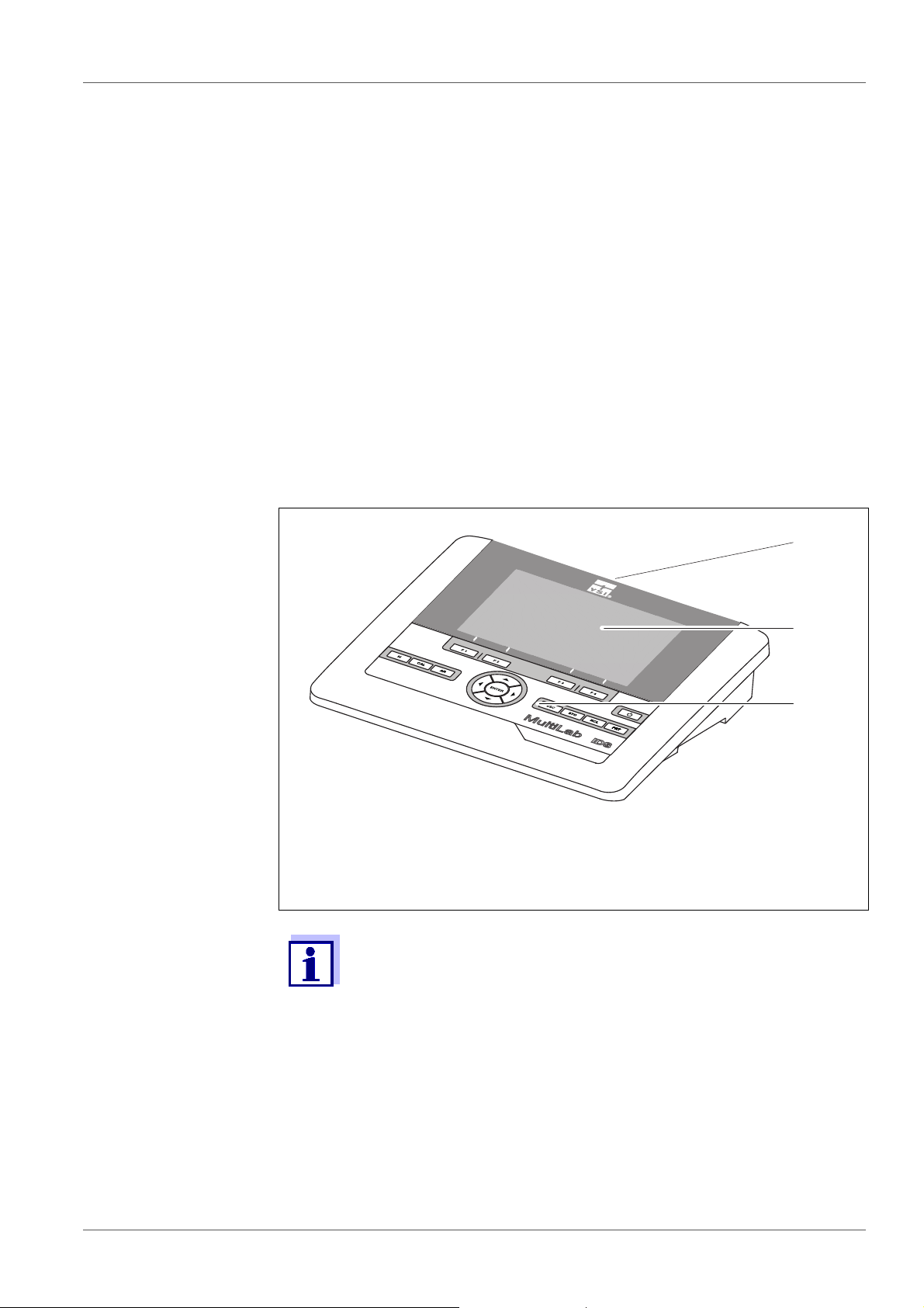
1 Overview
1.1 Meter MultiLab 4010-3
The compact, digital precision meter MultiLab 4010-3 enables you to carry out
pH measurements, ORP measurements, conductivity measurements and dissolved oxygen (D.O.) measurements quickly and reliably.
The MultiLab 4010-3 provides the maximum degree of operating comfort, reliability and measuring certainty for all applications.
The MultiLab 4010-3 supports you in your work with the following functions:
proven calibration procedures
automatic stability control (AR),
automatic sensor recognition
CMC (continuous measurement control)
QSC (sensor quality control).
1 Keypad (antibacterial)
2Display
3 Connectors
Due to its antibacterial properties, the keypad of the
MultiLab 4010-3 is especially suitable for applications in an environment where hygiene is important (see
DATA, page 94).
SECTION 14.2 GENERAL
ba76143e01 04/2013 7
Page 8

Overview MultiLab 4010-3
1.2 Sensors
1.2.1 IDS sensors
IDS sensors
support the automatic sensor recognition
show only the settings relevant to the specific sensor in the setting menu
process signals in the sensor digitally so that precise and interference-free
measurements are enabled even with long cables
facilitate to assign a sensor to a measured parameter with differently colored
couplings
have quick-lock couplings with which to fix the sensors to the meter.
Sensor data from
IDS sensors
IDS sensors transmit the following sensor data to the meter:
SENSOR ID
– Sensor name
– Sensor series number
Calibration data
Measurement settings
The calibration data are updated in the IDS sensor after each calibration procedure. A message is displayed while the data are being updated in the sensor.
In the measured value display, you can display the sensor name
and series number of the selected sensor with the [Info] softkey.
You can then display further sensor data stored in the sensor with
the [More] softkey (see section 4.1.6 S
ENSOR INFO, page 17).
8 ba76143e01 04/2013
Page 9

MultiLab 4010-3 Overview
1.2.2 IDS adapter for analog pH sensors
With the aid of an IDS adapter, you can also operate analog sensors
on the MultiLab 4010-3. The combination of the IDS adapter and analog sensor
behaves like an IDS sensor.
The MultiLab 4010-3 has a recess where the IDS adapter (ADA 94/IDS DIN or
ADA 94/IDS BNC), which is available as an accessory, can be permanently
mounted.
The IDS adapter replaces a digital input (channel 2) with a connector for an
analog pH sensor (DIN or BNC plug) and a temperature sensor.
1.2.3 Automatic sensor recognition
The automatic sensor recognition for IDS sensors allows
to operate an IDS sensor with different meters without recalibrating
to operate different IDS sensors at one meter without recalibration
to assign measurement data to an IDS sensor
– Measurement datasets are always stored and output with the sensor
name and sensor series number.
to assign calibration data to an IDS sensor
– Calibration data and calibration history are always stored and output with
the sensor name and sensor series number.
to activate the correct cell constant for conductivity sensors automatically
to hide menus automatically that do not concern this sensor
To be able to use the automatic sensor recognition, a meter that supports the
automatic sensor recognition (e.g. MultiLab 4010-3) and a digital IDS sensor
are required.
In digital IDS sensors, sensor data are stored that clearly identify the sensor.
The sensor data are automatically taken over by the meter.
ba76143e01 04/2013 9
Page 10
Safety MultiLab 4010-3
2Safety
2.1 Safety information
2.1.1 Safety information in the operating manual
This operating manual provides important information on the safe operation of
the meter. Read this operating manual thoroughly and make yourself familiar
with the meter before putting it into operation or working with it. The operating
manual must be kept in the vicinity of the meter so you can always find the information you need.
Important safety instructions are highlighted in this operating manual. They are
indicated by the warning symbol (triangle) in the left column. The signal word
(e.g. "Caution") indicates the level of danger:
WARNING
indicates a possibly dangerous situation that can lead to serious (irreversible) injury or death if the safety instruction is not
followed.
CAUTION
indicates a possibly dangerous situation that can lead to slight
(reversible) injury if the safety instruction is not followed.
NOTE
indicates a possibly dangerous situation where goods might be damaged
if the actions mentioned are not taken.
2.1.2 Safety signs on the meter
Note all labels, information signs and safety symbols on the meter. A warning
symbol (triangle) without text refers to safety information in this operating
manual.
2.1.3 Further documents providing safety information
The following documents provide additional information, which you should
observe for your safety when working with the measuring system:
• Operating manuals of sensors and other accessories
• Safety datasheets of calibration or maintenance accessories (such as buffer
solutions, electrolyte solutions, etc.)
2.2 Safe operation
2.2.1 Authorized use
The authorized use of the meter consists exclusively of the measurement of the
pH, ORP, conductivity and dissolved oxygen in a laboratory environment.
10 ba76143e01 04/2013
Page 11

MultiLab 4010-3 Safety
Only the operation and running of the meter according to the instructions and
technical specifications given in this operating manual is authorized (see
section 14 T
ECHNICAL DATA, page 94).
Any other use is considered unauthorized.
2.2.2 Requirements for safe operation
Note the following points for safe operation:
• The meter may only be operated according to the authorized use specified
above.
• The meter may only be supplied with power by the energy sources
mentioned in this operating manual.
• The meter may only be operated under the environmental conditions
mentioned in this operating manual.
• The meter may not be opened.
2.2.3 Unauthorized use
The meter must not be put into operation if:
• it is visibly damaged (e.g. after being transported)
• it was stored under adverse conditions for a lengthy period of time (storing
conditions, see section 14 T
ECHNICAL DATA, page 94).
ba76143e01 04/2013 11
Page 12

Commissioning MultiLab 4010-3
3 Commissioning
3.1 Scope of delivery
MeterMultiLab 4010-3
USB cable (A plug on mini B plug)
Power pack
Stand with stand base
Short instructions
Detailed operating manual
CD-ROM
3.2 Power supply
The MultiLab 4010-3 is supplied with power in the following ways:
Mains operation with the supplied power pack
Operation of the system clock with a buffer battery if there is no mains power
supply (see section 12.1.2 E
XCHANGING THE BATTERY, page 86).
3.3 Initial commissioning
Perform the following activities:
Connect the power pack
(see section 3.3.1 C
Switch on the meter
(see section 4.2 S
Set the date and time
(see section 4.5.5 E
page 25)
Mount the stand
(see operating manual of the stand)
ONNECTING THE POWER PACK, page 13)
WITCHING ON THE METER, page 19)
XAMPLE 2 ON NAVIGATION: SETTING THE DATE AND TIME,
12 ba76143e01 04/2013
Page 13
MultiLab 4010-3 Commissioning
3.3.1 Connecting the power pack
CAUTION
The line voltage at the operating site must lie within the input
voltage range of the original power pack (see section 14.2
G
ENERAL DATA, page 94).
CAUTION
Use original power packs only (see section 14.2 GENERAL DATA,
page 94).
1. Connect the plug of the power pack to the socket for the power pack on
the MultiLab 4010-3.
2. Connect the original power pack to an easily accessible power outlet.
The meter performs a self-test.
ba76143e01 04/2013 13
Page 14
Operation MultiLab 4010-3
4 Operation
4.1 General operating principles
4.1.1 Keypad
In this operating manual, keys are indicated by brackets <..> .
The key symbol (e.g. <ENTER>) generally indicates a short keystroke (press
and release) in this operating manual. A long keystroke (hold for approx. 2 sec)
is indicated by the underscore behind the key symbol (e.g. <ENTER
_>).
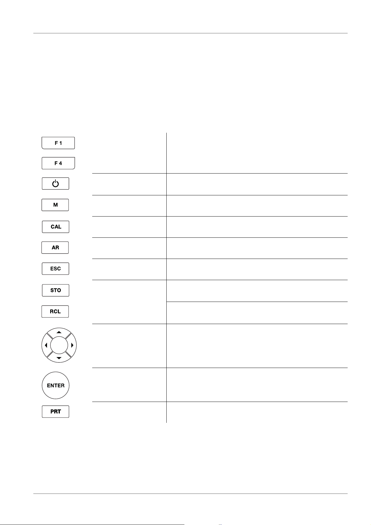
<F1>
<F4>
<On/Off> Switches the meter on or off
<M> Selects the measured parameter
<CAL>
_>
<CAL
<AR> Freezes the measured value (HOLD function)
<ESC> Switches back to the higher menu level /
<STO>
_>
<STO
<RCL>
<RCL
_>
Softkeys providing situation dependent functions, e.g.:
<F1>/[Info]: View information on a sensor
Calls up the calibration procedure
Displays the calibration data
Switches the AutoRead measurement on or off
Cancels inputs
Saves a measured value manually
Opens the menu for the automatic save function
Displays the manually stored measured values
Displays the automatically stored measured values
<><>
<><>
<ENTER>
<ENTER
<PRT>
<PRT_>
14 ba76143e01 04/2013
_>
Menu control, navigation
Opens the menu for measurement settings / Confirms
entries
Opens the menu for system settings
Outputs stored data to the interface
Outputs displayed data to the interface at intervals
Page 15

MultiLab 4010-3 Operation
4
3
2
5
7
8
9
6
1
HOLD AR
AutoCal TEC
03.04.2013 08:00Info
YSI
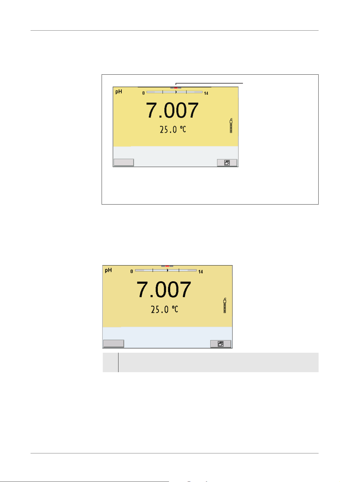
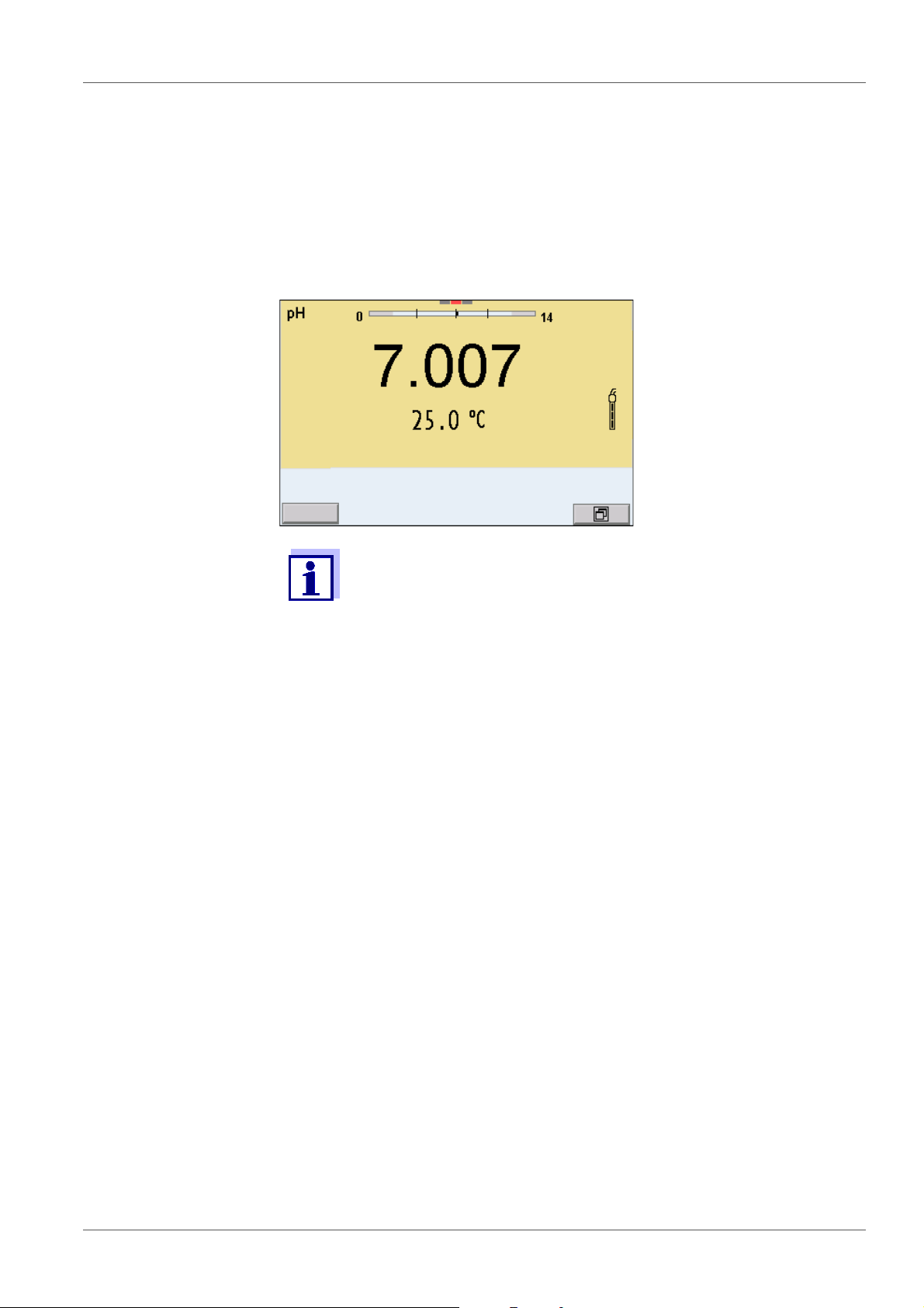
4.1.2 Display
Example (pH):
1 Status information (meter)
2 Status information (sensor)
3 Measured value
4 Measured parameter
5 Continuous measurement control (CMC function)
6 Channel display: Plug position of the sensor
7 Sensor symbol (calibration evaluation, calibration interval)
8 Measured temperature (with unit)
9 Softkeys and date + time
4.1.3 Status information
AutoCal
e.g. YSI
ConCal Calibration with any buffers
Error An error occurred during calibration
AR Stability control (AutoRead) is active
HOLD Measured value is frozen (<AR> key)
Calibration with automatic buffer recognition, e.g. with the buffer set: YSI buffers
Data are automatically output to the USB-B interface at intervals
Data are output to the USB-A interface (USB flash drive)
Data are output to the USB-A interface (USB printer). If there is a USB-B
connection at the same time (e.g. to a PC), the data are output to the USBB interface only.
Connection to a PC is active (USB-B interface)
ba76143e01 04/2013 15
Page 16
Operation MultiLab 4010-3
746
3 51
bac
2
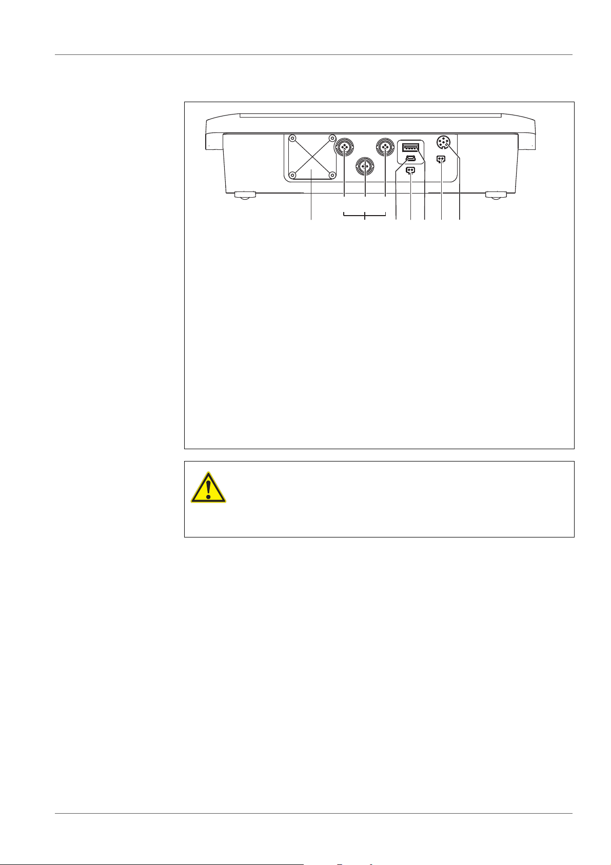
4.1.4 Instrument connectors
1 IDS sensors: (pH, ORP, conductivity, D.O.)
a) Channel 1
b) Channel 2
c) Channel 3
2 USB B (device) interface
3 Stirrer (ProOBOD)
4 USB-A (host) interface
5 Power pack
6 Service interface
7 Cover plate
The cover plate closes the mounting slot for the IDS adapter (4010-2/
3 pH Adapter DIN or 4010-2/3 pH Adapter BNC) available as an
accessory
CAUTION
Only connect sensors to the meter that cannot return any voltages or currents that are not allowed (> SELV and > current circuit with current limiting).
YSI IDS sensors and IDS adapters meet these requirements.
16 ba76143e01 04/2013
Page 17
MultiLab 4010-3 Operation
1
03.04.2013 08:00
Info
03.04.2013 08:00Info
4.1.5 Channel display
The MultiLab 4010-3 manages the connected sensors and displays which sensor is plugged to which connection.
1 Channel display: Display of the plug position for the respective
parameter
The red bar indicates for each connected sensor to which plug position (channel) of the meter it is connected.
4.1.6 Sensor info
You can display the current sensor data and sensor settings of a connected
sensor at any time. The sensor data are available in the measured value display with the /[Info] softkey.
1. In the measured value display:
Display the sensor data (sensor name, series number) with [Info].
ba76143e01 04/2013 17
Page 18
Operation MultiLab 4010-3
03.04.2013 08:00
More
4110
B092500013
03.04.2013 08:00
Man. temperature: 25 °C
pH resolution 0.001
mV resolution 0.1
Buffer YSI
Calibration interval 7d
Unit for slope mV/pH
QSC: off
Software version 1.00
4110
B092500013
03.04.2013 08:00Info
03.04.2013 08:00Info
2. Display further sensor data (settings) with [More].
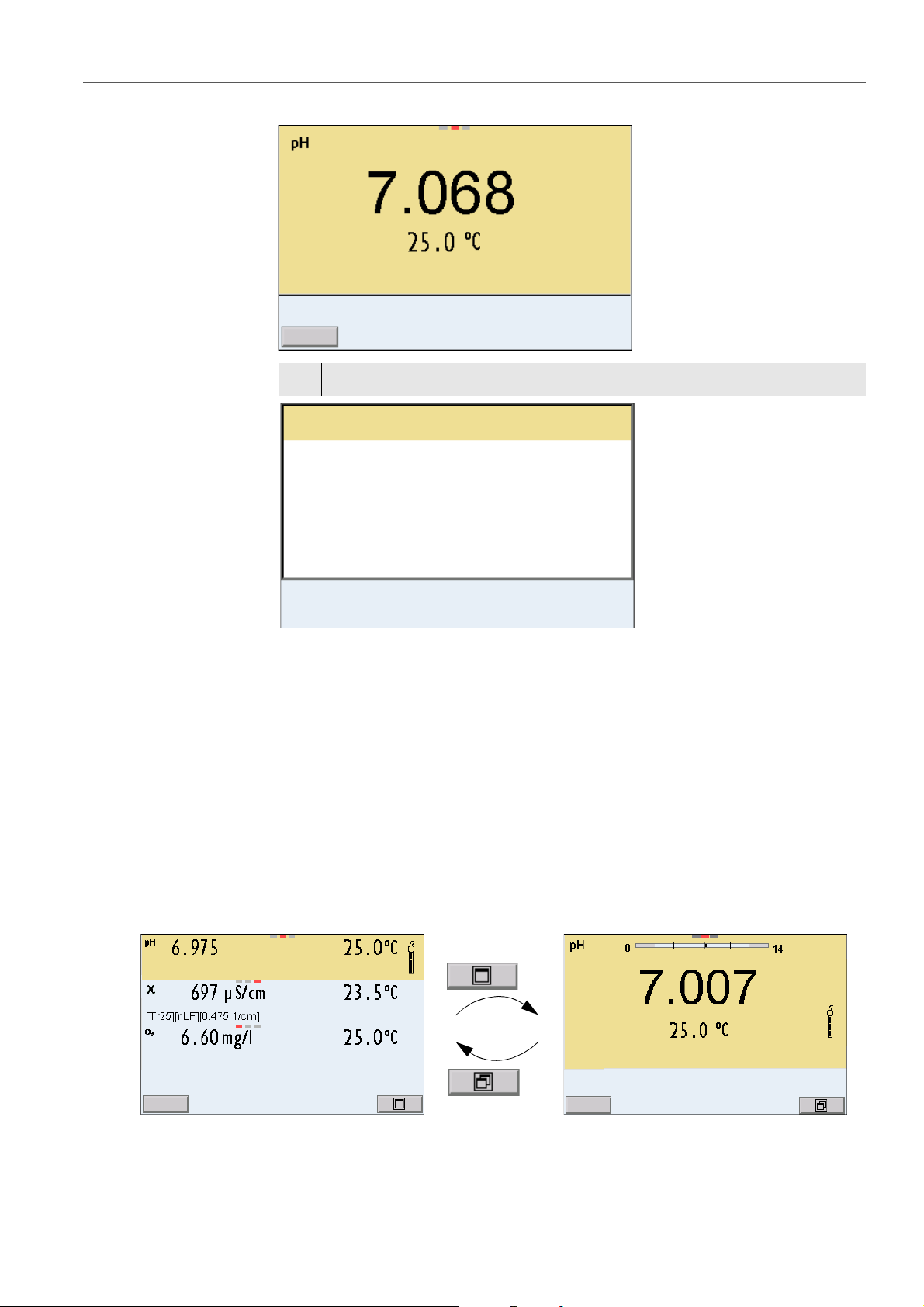
4.1.7 Display of several sensors in the measuring mode
The measured values of the connected sensors can be displayed in the following ways:
Clear display of all connected sensors
Detailed display of one sensor
(e.g. incl. CMC feature with pH sensors)
With the softkey you can very easily switch between the two display types. The
suitable softkey is displayed depending on the operating situation.
18 ba76143e01 04/2013
Page 19
MultiLab 4010-3 Operation
03.04.2013 08:00
Info
4.2 Switching on the meter
1. Switch the meter on with <On/Off>.
The meter performs a self-test.
2. Connect the sensor.
The meter is ready to measure.
If the user administration function is activated, the Login dialog
appears after the meter is switched on (see section 4.4 L
USER NAME, page 19).
OGIN WITH
The user administration function is not active in the delivery condition.
4.3 Switching off the meter
1. Switch off the meter with <On/Off>.
4.4 Login with user name
After activation of the user administration by the administrator, measurements
are only possible after login with a user name. The user name is documented
with the measured values and in records.
All user names entered by the administrator are listed in the User name menu.
The administrator determines for each user whether or not a password is
required for the login to the meter.
If the Password menu item is grayed out, no password is required for the login.
1. Switch on the meter with <On/Off>.
The Login dialog appears.
ba76143e01 04/2013 19
Page 20
Operation MultiLab 4010-3
User name Admin
Password ####
Change password
Login
03.04.2013 08:00
2. Using <><>, select the menu item, User name and confirm with
<ENTER>.
The user name is highlighted.
3. Using <><>, select a user name and confirm with <ENTER>.
The login is done immediately if no password is required.
If a sensor is connected the measured value display appears.
4. If a password is required:
Using <><>, select the menu item, Password and confirm with
<ENTER>.
The user specifies the password when he or she first logs in with a
user name.
A valid password consists of 4 digits.
The user can change the password with the next login.
5. Change the digit of the highlighted position with <><>.
Switch to the next position of the password with <><>.
When the password was completely entered, confirm with <ENTER>.
The login takes place. If a sensor is connected the measured value display appears.
Changing the
If the administrator has set up the access with password protection:
password
1. Switch on the meter with <On/Off>.
2. Using <><>, select the menu item, User name and confirm with
3. Using <><>, select a user name and confirm with <ENTER>.
4. Using <><>, select the menu item, Change password and confirm
20 ba76143e01 04/2013
The Login dialog appears.
<ENTER>.
The user name is highlighted.
with <ENTER>.
Page 21
MultiLab 4010-3 Operation
5. In the Password field, enter the old password with <><> and
<><>and confirm it with <ENTER>.
6. In the New password field, enter the new password with <><> and
<><>and confirm it with <ENTER>.
The password is changed.
The login takes place. If a sensor is connected the measured value display appears.
Forgotten the
password?
Contact the administrator.
4.5 Navigation
4.5.1 Operating modes
Operating
mode
Measuring The measurement data of the connected sensor are shown
Calibration The course of a calibration with calibration information, func-
Storage in
memory
Transmittin
g data
Setting The system menu or a sensor menu with submenus, set-
Explanation
in the measured value display
tions and settings is displayed
The meter stores measuring data automatically or manually
The meter transmits measuring data and calibration records
to a USB interface automatically or manually.
tings and functions is displayed
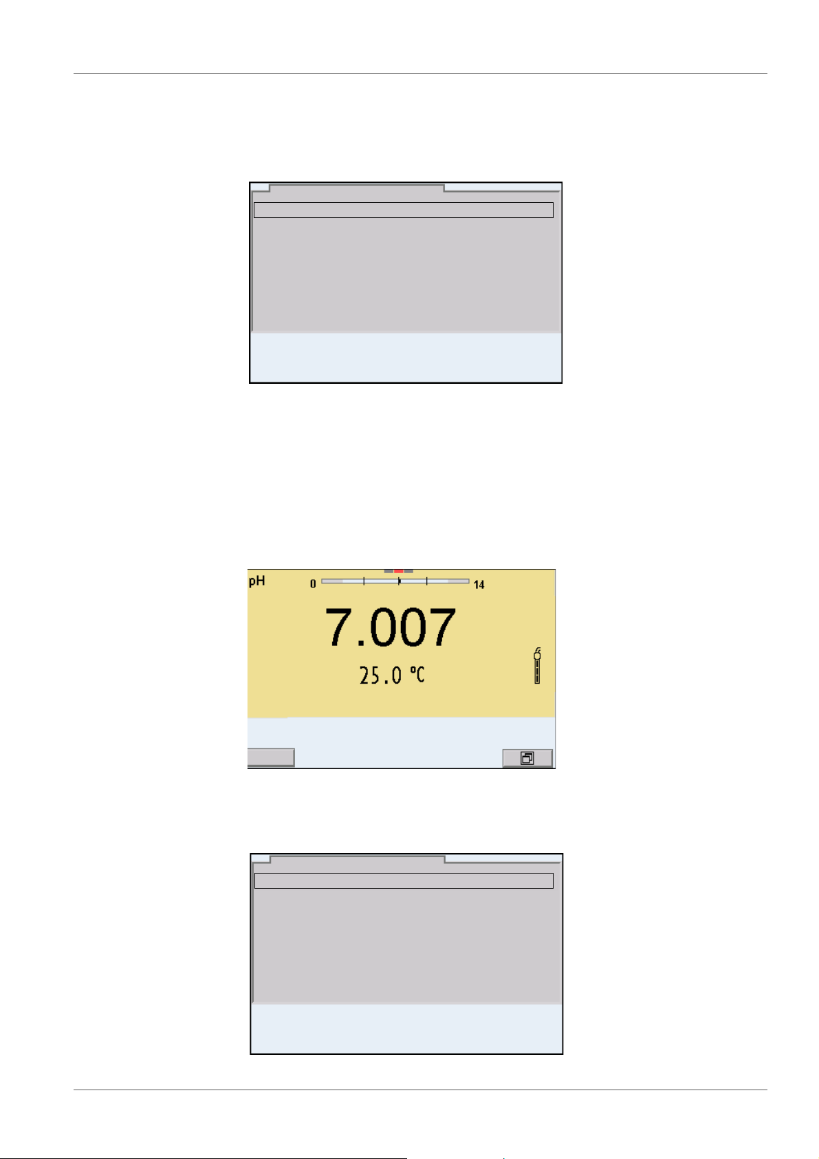
4.5.2 Measured value display
In the measured value display, you can
use <><> to select one of several connected sensors. The selected
sensor is displayed with a colored background.
The following actions / menus refer to the selected sensor
open the menu for calibration and measurement settings with <ENTER>
(short
open the Storage & config menu with the sensor-independent settings by
pressing <ENTER
change the display in the selected measuring screen (e. g. pH <−> mV) by
pressing <M>.
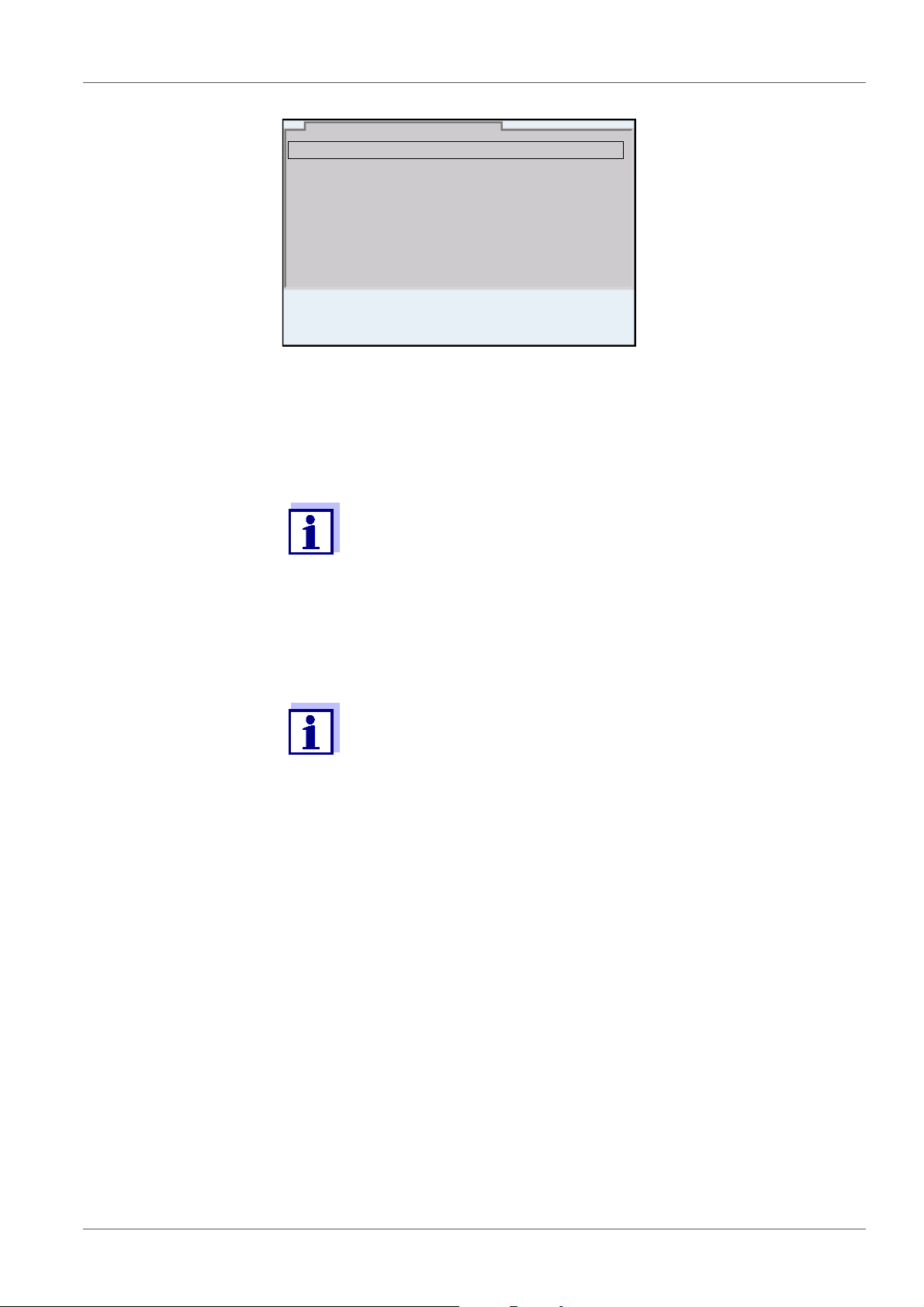
4.5.3 Menus and dialogs
The menus for settings and dialogs in procedures contain further subelements.
ba76143e01 04/2013 21
keystroke)
_> (long keystroke, approx. 2 s).
Page 22
Operation MultiLab 4010-3
General
Interface
Clock function
Service information
Reset
System
03.04.2013 08:00
Language: English
Audio signal: on
Brightness: 12
Temperature unit: °C
Stability control: on
General
03.04.2013 08:00
pH
03.04.2013 08:00
Calibration record
Calibration data storage
Buffer: YSI
Single-point calibration: yes
Calibration interval: 7 d
Unit for slope: mV/pH
[
i
] 2.00 4.00 7.00 10.00
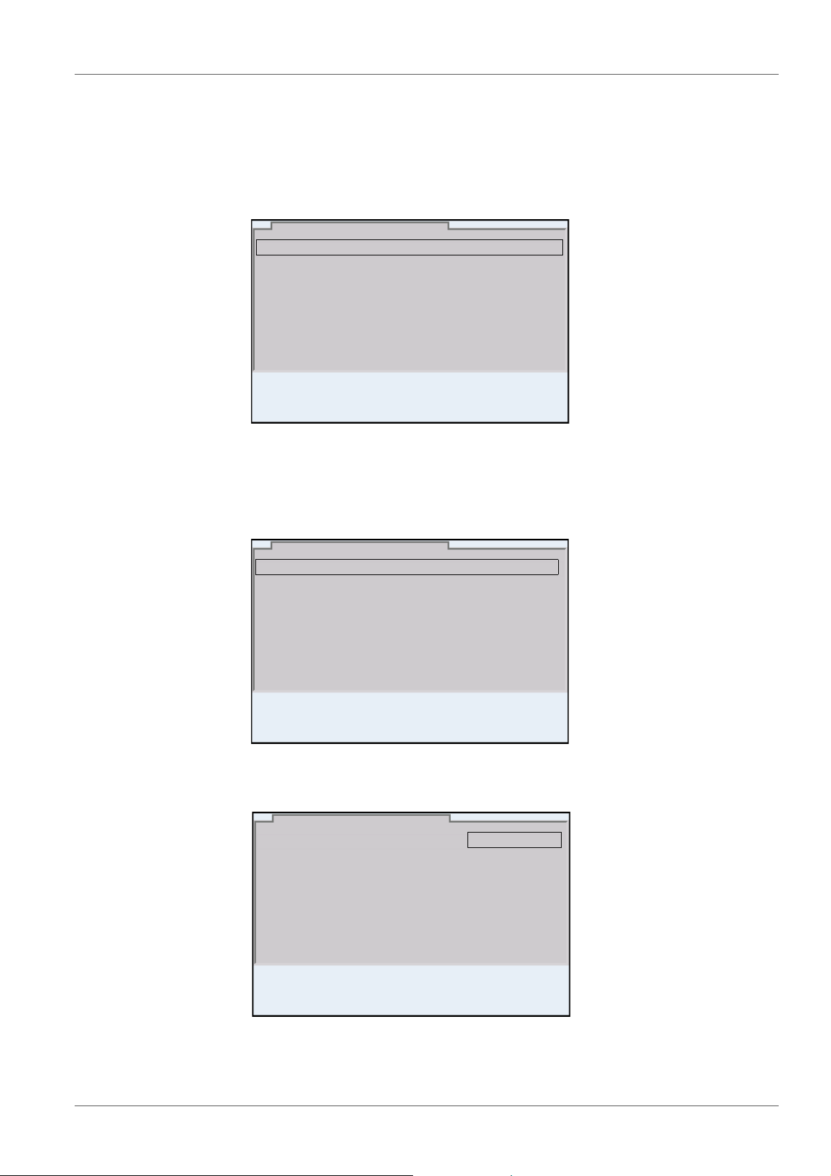
The selection is made with the <><> keys. The current selection is displayed with a frame.
Submenus
The name of the submenu is displayed at the upper edge of the frame. Submenus are opened by confirming with <ENTER>. Example:
Settings
Settings are indicated by a colon. The current setting is displayed on the
right-hand side. The setting mode is opened with <ENTER>. Subsequently,
the setting can be changed with <><> and <ENTER>. Example:
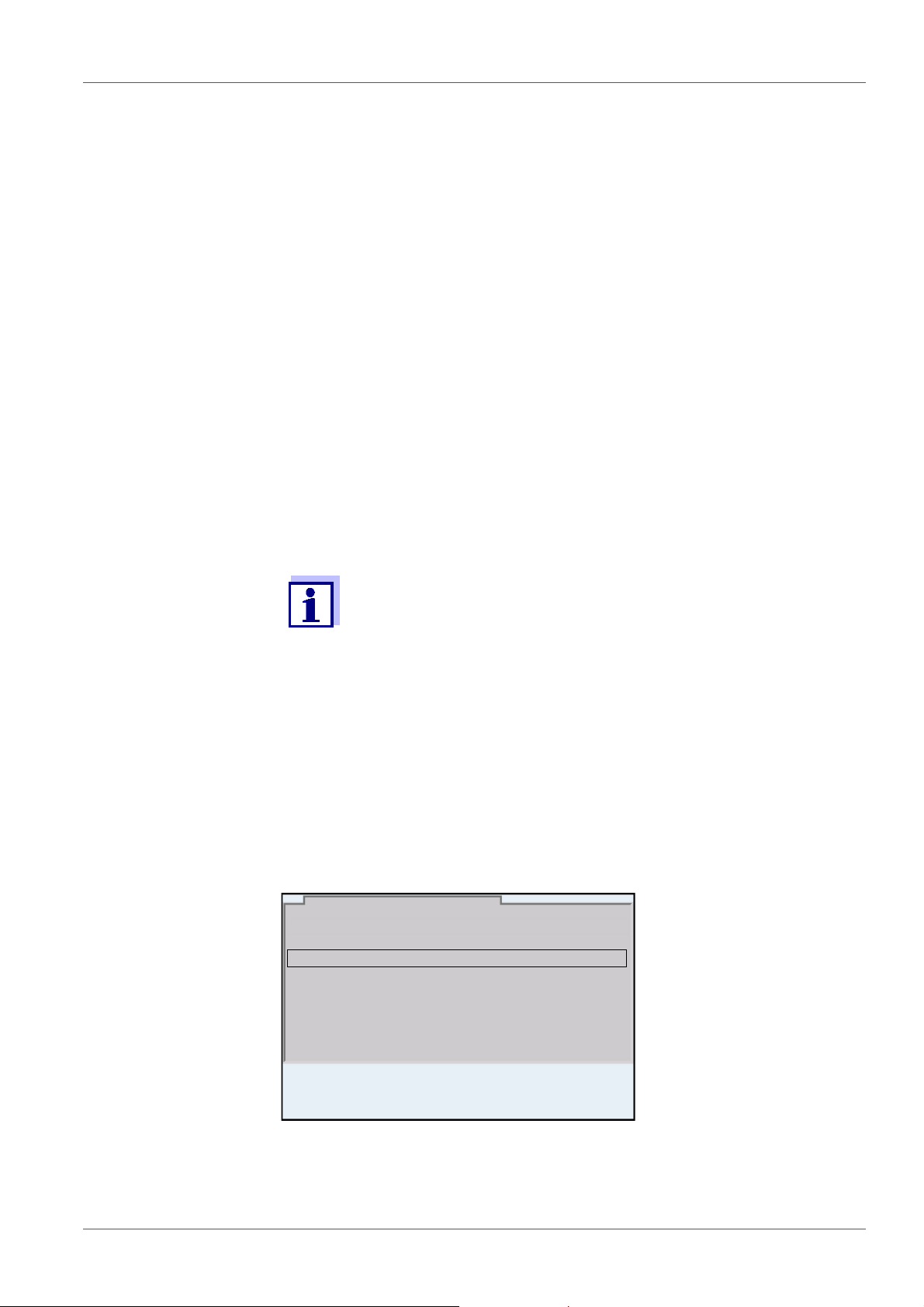
Functions
Functions are designated by the name of the function. They are immediately
carried out by confirming with <ENTER>. Example: Display the Calibration
record function.
22 ba76143e01 04/2013
Page 23
MultiLab 4010-3 Operation
Calibration record
Calibration data storage
Buffer: YSI
Single-point calibration: yes
Calibration interval: 7 d
Unit for slope: mV/pH
[i] 2.00 4.00 7.00 10.00
pH
03.04.2013 08:00
03.04.2013 08:00
Info
System
Data storage
Storage & config
03.04.2013 08:00
Messages
Information is marked by the [
i
] symbol. It cannot be selected. Example:
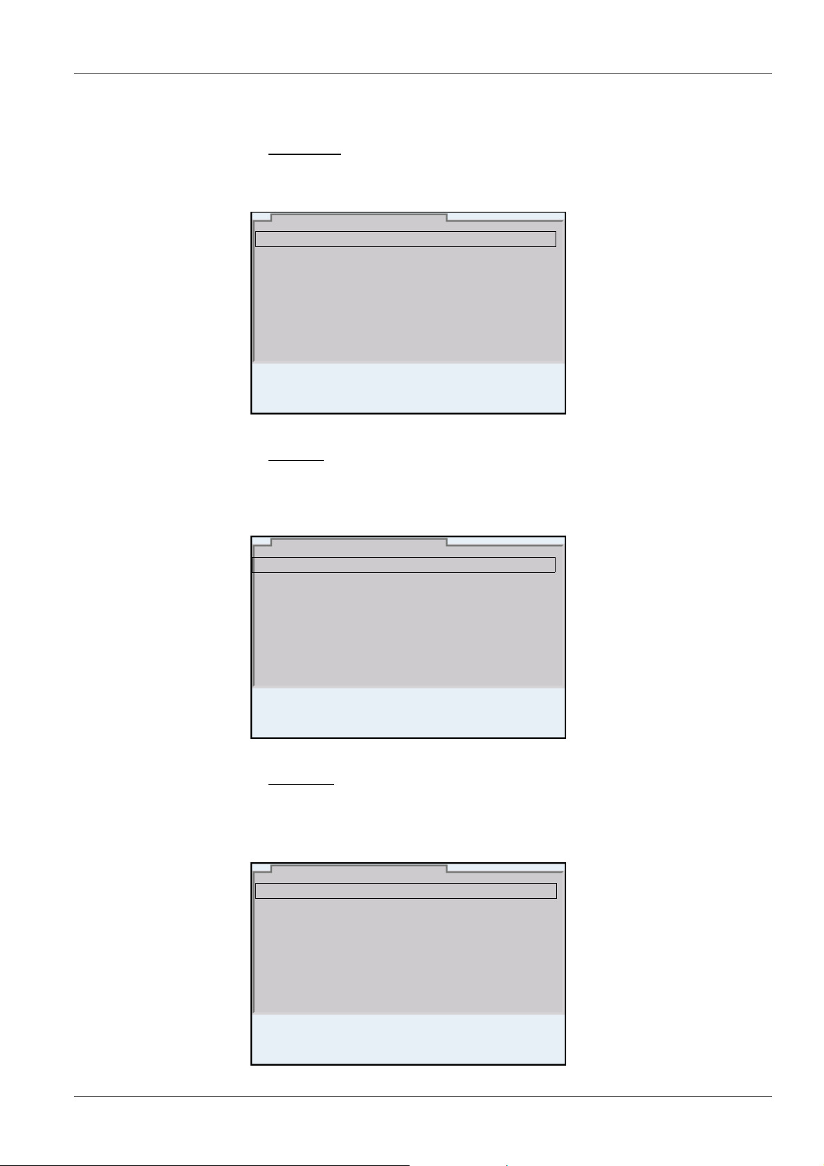
4.5.4 Example 1 on navigation: Setting the language
1. Press the <On/Off> key.
The measured value display appears.
The instrument is in the measuring mode.
2. Open the Storage & config menu with <ENTER
The instrument is in the setting mode.
_>.
ba76143e01 04/2013 23
Page 24
Operation MultiLab 4010-3
General
Interface
Clock function
Service information
Reset
System
03.04.2013 08:00
Language: English
Audio signal: on
Brightness: 12
Temperature unit: °C
Stability control: on
General
03.04.2013 08:00
Language: English
Audio signal: on
Brightness: 12
Temperature unit: °C
Stability control: on
General
03.04.2013 08:00
3. Select the System submenu with <><>.
The current selection is displayed with a frame.
4. Open the System submenu with <ENTER>.
5. Select the General submenu with <><>.
The current selection is displayed with a frame.
6. Open the General
submenu with <ENTER>.
7. Open the setting mode for the Language with <ENTER>.
24 ba76143e01 04/2013
8. Select the required language with <><>.
Page 25
MultiLab 4010-3 Operation
Date format: dd.mm.yy
Date: 03.04.2013
Time: 14:53:40
Clock function
03.04.2013 08:00
9. Confirm the setting with <ENTER>.
The meter switches to the measuring mode.
The selected language is active.
4.5.5 Example 2 on navigation: Setting the date and time
The meter has a clock with a date function. The date and time are indicated in
the status line of the measured value display.
When storing measured values and calibrating, the current date and time are
automatically stored as well.
The correct setting of the date and time and date format is important for the following functions and displays:
Current date and time
Calibration date
Identification of stored measured values.
Setting the date,
time and date format
Therefore, check the time at regular intervals.
The date and time are reset (to 01.01.2012 00:00 hours), if the following conditions are met:
the supply voltage failed and
the buffer batteries for the system clock are empty.
The date format can be switched from the display of day, month, year
(dd.mm.yy) to the display of month, day, year (mm/dd/yy or mm.dd.yy).
1. In the measured value display:
Open the Storage & config menu with <ENTER
_>.
The instrument is in the setting mode.
2. Select and confirm the System / Clock function menu with <><>
and <ENTER>.
The setting menu for the date and time opens up.
ba76143e01 04/2013 25
3. Select and confirm the Time menu with <><> and <ENTER>.
The hours are highlighted.
Page 26

Operation MultiLab 4010-3
4. Change and confirm the setting with <><> and <ENTER>.
The minutes are highlighted.
5. Change and confirm the setting with <><> and <ENTER>.
The seconds are highlighted.
6. Change and confirm the setting with <><> and <ENTER>.
The time is set.
7. If necessary, set the Date and Date format. The setting is made simi-
larly to that of the time.
8. To make further settings, switch to the next higher menu level with
<ESC>.
or
Switch to the measured value display with <M>.
The instrument is in the measuring mode.
26 ba76143e01 04/2013
Page 27
MultiLab 4010-3 pH value
03.04.2013 08:00Info
5 pH value
5.1 Measuring
5.1.1 Measuring the pH value
The sensor connection and the USB-B (device) interface are galvanically isolated. This facilitates interference-free measurements
also in the following cases:
Measurement in grounded test samples
Measurement with several sensors connected to one
MultiLab 4010-3 in one test sample
1. Connect the IDS pH sensor to the meter.
The pH measuring window is displayed.
2. If necessary, select the measured parameter with <M>.
Stability control
(AutoRead)
& HOLD function
3. Adjust the temperature of the solutions and measure the current tem-
perature if the measurement is made without a temperature sensor.
4. If necessary, calibrate or check the IDS pH sensor.
5. Immerse the IDS pH sensor in the test sample.
The stability control function (AutoRead) continually checks the stability of the
measurement signal. The stability has a considerable impact on the reproducibility of measured values.
The measured parameter flashes on the display
as soon as the measured value is outside the stability range
when the automatic Stability control is switched off.
You can start the Stability control manually at any time, irrespective of the set-
ting for automatic Stability control (see section 9.5.3 A
TROL, page 72) in the System menu.
UTOMATIC STABILITY CON-
1. Freeze the measured value with <AR>.
The [HOLD] status indicator is displayed.
The HOLD function is active.
ba76143e01 04/2013 27
Page 28
pH value MultiLab 4010-3
You can terminate the Stability control function and the HOLD function with <AR> or <M> at any time.
2. Using <ENTER>, activate the Stability control function manually.
The [AR] status indicator appears while the measured value is assessed
as not stable. A progress bar is displayed and the display of the measured parameter flashes.
As soon as a measured value meets the stability criteria, it is frozen. The
[HOLD][AR] status indicator is displayed, the progress bar disappears
and the display of the measured parameter stops flashing.
The current measurement data is output to the interface. Measurement
data meeting the stability control criterion is marked by AR.
You can prematurely terminate the Stability control function manually with <ENTER> at any time. When the Stability control function
is prematurely terminated, the current measurement data are output to the interface (PC, USB memory device or USB printer) without AutoRead info.
Criteria for a stable
measured value
3. Using <ENTER>, start a further measurement with stability control.
or
Release the frozen measured value again with <AR> or <M>.
The [AR] status display disappears. The display switches back to the previous indication.
The Stability control function checks whether the measured values are stable
within the monitored time interval.
Measured
Time interval Stability in the time interval
parameter
pH value 15 seconds
Temperature 15 seconds
Δ : Better than 0.01 pH
Δ : Better than 0.5 °C
The minimum duration until a measured value is assessed as stable is the
monitored time interval. The actual duration is mostly longer.
5.1.2 Measuring the temperature
For reproducible pH measurements, it is essential to measure the temperature
of the test sample.
IDS sensors measure the temperature with a temperature sensor integrated in
the IDS sensor.
When operating a sensor without integrated temperature sensor, e.g.
via an IDS pH adapter, you have to measure and enter the temperature of the
test sample first.
28 ba76143e01 04/2013
Page 29
MultiLab 4010-3 pH value
The display of the temperature indicates the active temperature measuring
mode:
Temperature
sensor
Resolution of the
temp. display
Temp. measurement
Yes 0.1 °C Automatic with temperature
sensor
- 1 °C Manual
5.2 pH calibration
5.2.1 Why calibrate?
pH electrodes age. This changes the zero point (asymmetry) and slope of the
pH electrode. As a result, an inexact measured value is displayed. Calibration
determines and stores the current values of the zero point and slope of the
electrode.
Thus, you should calibrate at regular intervals.
5.2.2 When do you have to calibrate?
Routinely within the framework of the company quality assurance
When the calibration interval has expired
5.2.3 Carrying out automatic calibration (AutoCal)
Make sure that in the sensor menu, Buffer menu, the buffer set is correctly
selected (see section 9.1.1 S
ETTINGS FOR PH MEASUREMENTS, page 61).
Use one to five buffer solutions of the selected buffer set in any order.
Below, calibration with YSI buffers (YSI) is described. When other buffer sets
are used, other nominal buffer values are displayed. Apart from that, the procedure is identical.
If single-point calibration was set in the menu, the calibration procedure is automatically finished with the measurement of buffer solution 1 and the calibration record is displayed.
1. Connect the pH sensor to the meter.
The pH measuring window is displayed.
2. Keep the buffer solutions ready.
When measuring without temperature sensor:
Temper the buffer solutions or measure the current temperature.
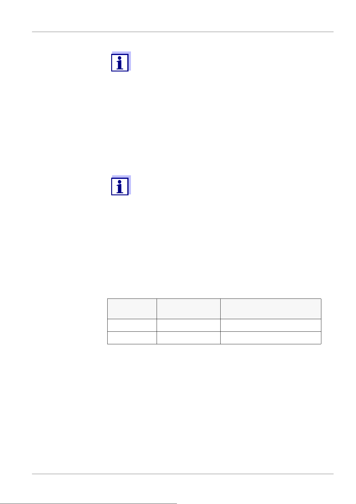
3. Start the calibration with <CAL>.
The calibration display for the first buffer appears (voltage display).
ba76143e01 04/2013 29
Page 30
pH value MultiLab 4010-3
03.04.2013 08:00
YSI
03.04.2013 08:00
YSI
10.000
4. Thoroughly rinse the sensor with deionized water.
5. Immerse the sensor in the first buffer solution.
6. For measurements without temperature sensor
(e.g. when using an IDS adapter
):
Enter the temperature of the buffer with <><>.
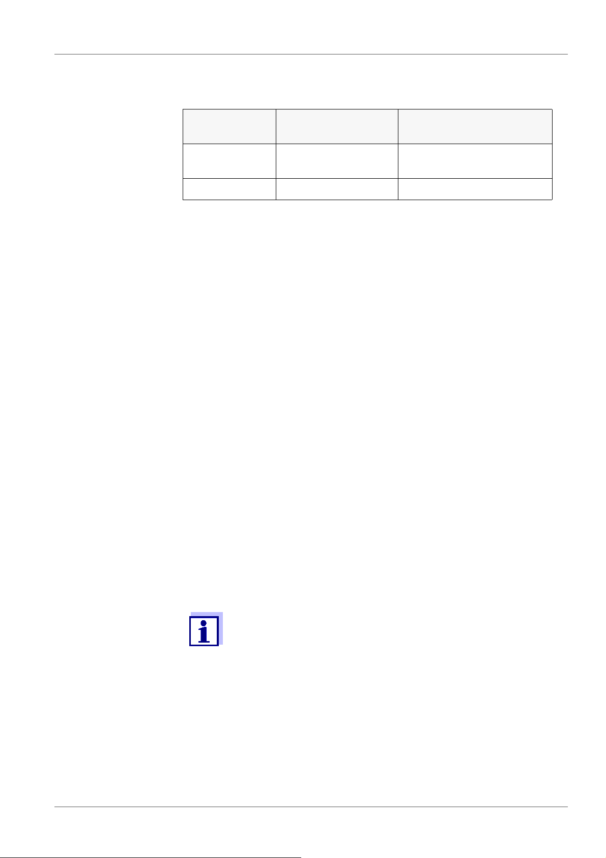
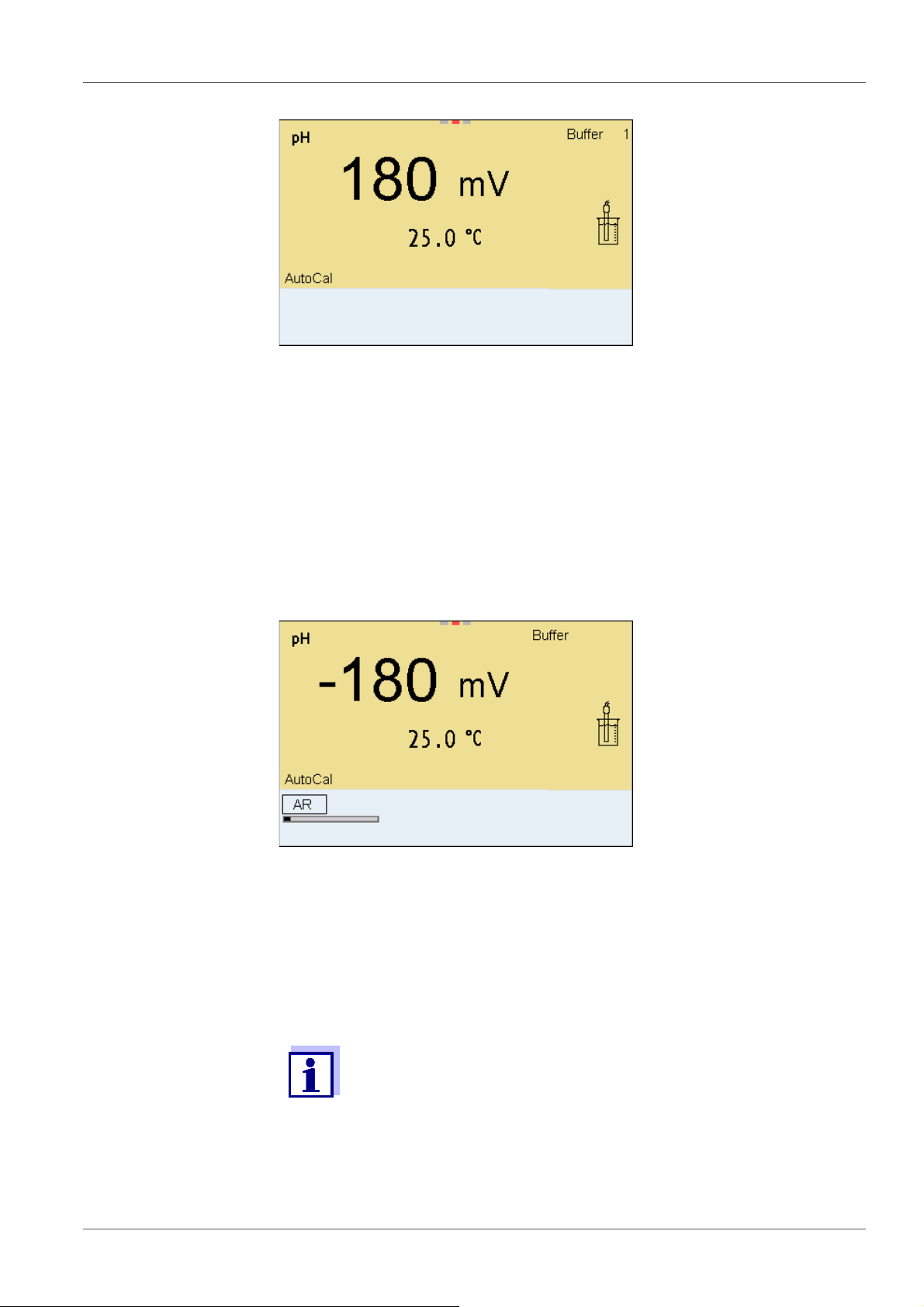
7. Start the measurement with <ENTER>.
The measured value is checked for stability (stability control).
The [AR] status indicator is displayed. The measured parameter
flashes.
8. Wait for the end of the measurement with stability control or accept the
calibration value with <ENTER>.
The calibration display for the next buffer appears (voltage display).
9. If necessary, finish the calibration procedure as a single-point calibration
with <M>.
The calibration record is displayed.
For single-point calibration, the instrument uses the Nernst slope
(-59.2 mV/pH at 25 °C) and determines the zero point of the IDS pH
sensor.
Continuing with two-
point calibration
10. Thoroughly rinse the sensor with deionized water.
11. Immerse the pH sensor in buffer solution 2.
30 ba76143e01 04/2013
Page 31

MultiLab 4010-3 pH value
03.04.2013 08:00
YSI
12. When measuring without temperature sensor:
Enter the temperature of the buffer with <><>.
13. Start the measurement with <ENTER>.
The measured value is checked for stability (stability control).
The [AR] status indicator is displayed. The measured parameter
flashes.
Continuing with
three- to five-point
calibration
14. Wait for the measurement with stability control to be completed or termi-
nate the stability control and take over the calibration value with
<ENTER>.
The calibration display for the next buffer appears (voltage display).
15. If necessary, finish the calibration procedure as a two-point calibration
with <M>.
The calibration record is displayed.
16. Thoroughly rinse the sensor with deionized water.
17. Immerse the sensor in the next buffer solution.
18. When measuring without temperature sensor:
Enter the temperature of the buffer with <><>.
19. Start the measurement with <ENTER>.
The measured value is checked for stability (stability control).
The [AR] status indicator is displayed. The measured parameter
flashes.
ba76143e01 04/2013 31
Page 32

pH value MultiLab 4010-3
03.04.2013 08:00
YSI
4.000
20. Wait for the measurement with stability control to be completed or termi-
nate the stability control and take over the calibration value with
<ENTER>.
The calibration display for the next buffer appears (voltage display).
21. If necessary, use <M> to finish the calibration.
The calibration record is displayed.
or
Switch to calibration with the next buffer with <ENTER>.
Calibration is automatically completed after the last buffer of a buffer set has been measured. Then the calibration record is displayed.
The calibration line is determined by linear regression.
5.2.4 Carrying out a manual calibration (ConCal)
Make sure that in the sensor menu, Buffer menu, the ConCal buffer set is
correctly selected (see section 9.1.1 S
ETTINGS FOR PH MEASUREMENTS, page
61).
Use any one to five buffer solutions in ascending or descending order.
If single-point calibration was set in the menu, the calibration procedure is automatically finished with the measurement of buffer solution 1 and the calibration record is displayed.
1. Connect the pH sensor to the meter.
The pH measuring window is displayed.
2. Keep the buffer solutions ready.
When measuring without temperature sensor:
Temper the buffer solutions or measure the current temperature.
3. Start the calibration with <CAL>.
The calibration display for the first buffer appears (voltage display).
32 ba76143e01 04/2013
Page 33

MultiLab 4010-3 pH value
03.04.2013 08:00
03.04.2013 08:00
03.04.2013 08:00
4. Thoroughly rinse the sensor with deionized water.
5. Immerse the pH sensor in buffer solution 1.
6. For measurements without temperature sensor
(e.g. when using an IDS adapter
):
Enter the temperature of the buffer with <><>.
7. Start the measurement with <ENTER>.
The measured value is checked for stability (stability control).
The [AR] status indicator is displayed. The measured parameter flashes.
8. Wait for the measurement with stability control to be completed or ter-
minate the stability control and take over the calibration value with
<ENTER>.
The pH value of the buffer solution is displayed.
ba76143e01 04/2013 33
Page 34

pH value MultiLab 4010-3
03.04.2013 08:00
9. Set the nominal buffer value for the measured temperature with
<><>.
10. Accept the calibration value with <ENTER>.
The calibration display for the next buffer appears (voltage display).
11. If necessary, finish the calibration procedure as a single-point calibration
with <M>.
The calibration record is displayed.
For single-point calibration, the instrument uses the Nernst slope
(-59.2 mV/pH at 25 °C) and determines the zero point of the IDS pH
sensor.
Continuing with two-
point calibration
12. Thoroughly rinse the sensor with deionized water.
13. Immerse the pH sensor in buffer solution 2.
14. When measuring without temperature sensor:
Enter the temperature of the buffer with <><>.
15. Start the measurement with <ENTER>.
The measured value is checked for stability (stability control).
The [AR] status indicator is displayed. The measured parameter
flashes.
16. Wait for the measurement with stability control to be completed or ter-
minate the stability control and take over the calibration value with
<ENTER>.
The pH value of the buffer solution is displayed.
17. Set the nominal buffer value for the measured temperature with
<><>.
18. Accept the calibration value with <ENTER>.
The calibration display for the next buffer appears (voltage display).
19. If necessary, finish the calibration procedure as a two-point calibration
with <M>.
The calibration record is displayed.
34 ba76143e01 04/2013
Page 35

MultiLab 4010-3 pH value
03.04.2013 08:00
Continuing with
three- to five-point
calibration
20. Thoroughly rinse the sensor with deionized water.
21. Immerse the sensor in the next buffer solution.
22. When measuring without temperature sensor:
Enter the temperature of the buffer with <><>.
23. Start the measurement with <ENTER>.
The measured value is checked for stability (stability control).
The [AR] status indicator is displayed. The measured parameter
flashes.
24. Wait for the measurement with stability control to be completed or ter-
minate the stability control and take over the calibration value with
<ENTER>.
The pH value of the buffer solution is displayed.
25. Set the nominal buffer value for the measured temperature with
<><>.
26. Accept the calibration value with <ENTER>.
The calibration display for the next buffer appears (voltage display).
27. If necessary, use <M> to finish the calibration.
The calibration record is displayed.
or
Continue calibrating using the next buffer with <ENTER>.
After the fifth buffer has been measured the calibration is automatically finished. Then the calibration record is displayed.
The calibration line is determined by linear regression.
5.2.5 Calibration points
Calibration can be performed using one to five buffer solutions in any order
(single-point to five-point calibration). The meter determines the following
values and calculates the calibration line as follows:
ba76143e01 04/2013 35
Page 36

pH value MultiLab 4010-3
Calibration Determined val-
ues
1-point Asy Zero point = Asy
2-point Asy
Slp.
3-point to 5point
You can display the slope in the units, mV/pH or % (see section
9.1.1 S
5.2.6 Calibration data
Asy
Slp.
ETTINGS FOR PH MEASUREMENTS, page 61).
Displayed calibration data
Slope = Nernst slope
(-59.2 mV/pH at 25 °C)
Zero point = Asy
Slope = Slp.
Zero point = Asy
Slope = Slp.
The calibration line is calculated by
linear regression.
Displaying the cali-
bration data
The calibration record is automatically transmitted to the interface
after calibrating.
The calibration record of the last calibration is to be found under the menu item,
Calibration / Calibration record. To open it in the measured value display, press
the <CAL
The calibration records of the last 10 calibrations are to be found in the menu,
Calibration / Calibration data storage / Display. To open the Calibration menu,
press the <ENTER> key in the measured value display.
_> key.
36 ba76143e01 04/2013
Page 37

MultiLab 4010-3 pH value
Menu item Setting/
function
Calibration /
Calibration data storage /Display
Calibration / Calibration data storage /
Output to USB flash
drive or printer
- Displays the calibration records.
- Outputs the stored calibration data to
Explanation
Further options:
Scroll through the calibration
records with <><>.
Using <PRT>, output the dis-
played calibration record to the
USB-B (PC) interface or the USBA (USB printer) interface.
Using <PRT
bration records to the USB-B (PC)
interface or the USB-A (USB
printer) interface.
Quit the display with <ESC>.
Switch directly to the measured
value display with <M>.
the USB-A interface (USB memory
device/USB printer)
_>, output all cali-
Calibration evalua-
tion
Calibration /
Calibration data storage /
Output to RS232/USB
After calibrating, the meter automatically evaluates the calibration. The zero
point and slope are evaluated separately. The worse evaluation of both is taken
into account. The evaluation appears on the display and in the calibration
record.
Display Calibration
record
+++
++
+
- Outputs the stored calibration data to
the USB-B interface (PC)
Zero point
[mV]
-15 ... +15 -60.5 ... -58.0
-20 ... <-15
or
>+15 ... +20
-25 ... <-20
or
>+20 ... +25
Slope [mV/pH]
>-58.0 ... -57.0
-61.0 ... <-60.5
or
>-57.0 ... -56.0
-
ba76143e01 04/2013 37
-30 ... <-25
or
->+25 ... + 30
-62.0 ... <-61.0
or
>-56.0 ... -50.0
Page 38

pH value MultiLab 4010-3
CALIBRATION pH
03.04.2013 07:43:33
4110
Ser. no. B092500013
YSI
Buffer 1 4.00
Buffer 2 7.00
Buffer 3 10.00
Voltage 1 184.0 mV
Voltage 2 3.0 mV
Voltage 3 -177.0 mV
Temperature 1 24.0 °C
Temperature 2 24.0 °C
Temperature 3 24.0 °C
Slope -60.2 mV/pH
Asymmetry 4.0 mV
Sensor +++
etc...
Calibration record
Display Calibration
record
Clean the IDS sensor according
to the sensor operating manual
Error Error
Error elimination (see section 13
HAT TO DO IF..., page 89)
W
For pH IDS sensors you can optionally enable a more finely graded
calibration evaluation (QSC) (see section 5.2.8 QSC
(
SENSOR QUALITY CONTROL), page 40).
Zero point
[mV]
<-30
or
>+30
Slope [mV/pH]
<-62.0
or
> -50,0
FUNCTION
5.2.7 Continuous measurement control (CMC function)
The Continuous Measurement Control (CMC function) facilitates to evaluate
the current measured value instantly and definitely.
After each successful calibration the scale of the pH measuring range is
displayed in the measured value display. Here you can very clearly see
38 ba76143e01 04/2013
whether or not the current measured value is in the calibrated part of the
measuring range.
Page 39

MultiLab 4010-3 pH value
1
2
3
4
03.04.2013 08:00
Info
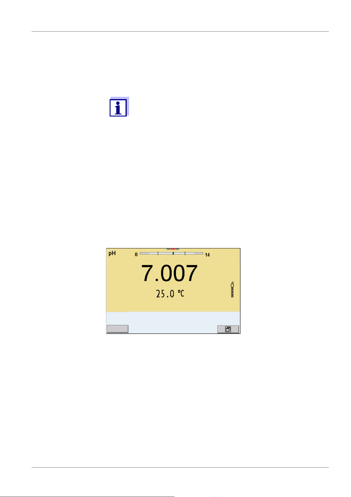
The following information is displayed:
1 Currently measured pH value (needle)
2 Marking lines for all nominal buffer values used with the last valid cali-
bration
3 Measuring range for which a valid calibration is available. Measured
values in this range are suitable for documentation.
4 Measuring range for which no valid calibration is available (dark
gray). Measured values in this range are not suitable for documentation. Calibrate the meter with buffers covering this measuring range.
If the current measured value is outside the calibrated range, this area
is displayed in a darker gray.
If a measured value is outside the measuring range pH 0 - 14, overflow arrows are displayed at the left or right edge of the measuring
range.
The limits of the calibrated range are determined by the buffers used for calibration:
Lower limit: Buffer with lowest pH value - 2 pH units
Upper limit: Buffer with highest pH value + 2 pH units
ba76143e01 04/2013 39
Page 40

pH value MultiLab 4010-3
03.04.2013 08:00
Info
1
5.2.8 QSC function (sensor quality control)
General information
on the QSC function
The QSC function (Quality Sensor Control) is a new sensor evaluation for
digital IDS sensors. It evaluates the condition of an IDS pH sensor individually
and with a very fine grading.
The QSC scale shows the current sensor evaluation with an indicator on the
display.
1 QSC scale
The double arrow on the QSC scale indicates the current sensor evaluation
In the USB output the sensor evaluation is given as a percentage (1-100).
The finely graded sensor evaluation of the QSC function promptly calls your
attention to changes of the sensor.
Thus you can do what is necessary to restore the optimum measuring quality
(e.g. clean, calibrate or replace the sensor).
Sensor evaluation
with / without
QSC function
With QSC function Without QSC function (sensor sym-
bol)
Very fine grading of the sensor evaluation (100 grades)
The reference value is individually
determined for each sensor during
Rough grading of the sensor evaluation (4 grades)
A theoretical reference value is used
for all sensors
the QSC initial calibration.
Low tolerances for zero point and
slope when using QSC buffer solutions
Additional QSC calibration required
Greater tolerances for zero point and
slope when using commercial buffer
sets
No additional calibration required
(with special QSC buffer set)
QSC calibration The QSC function is enabled by once carrying out an additional three-point cali-
bration with special QSC buffer solutions. It covers the measuring range of the
sensor (pH 2 to pH 11). The QSC initial calibration determines the actual condition of the sensor and stores it as a reference in the sensor.
To meet the high requirements of a QSC initial calibration, the QSC initial calibration should optimally be carried out with the initial commissioning of the
sensor.
40 ba76143e01 04/2013
Page 41

MultiLab 4010-3 pH value
03.04.2013 08:00
Carry out the normal calibrations for your special measuring range with your
usual standard solutions as previously done.
As soon as the QSC function was enabled for an IDS sensor, it is
not possible to return to the sensor evaluation with the sensor
symbol for this sensor.
Carrying out a QSC
initial calibration
1. Open the menu for measurement settings with <ENTER>.
2. In the QSC menu, select First calibration with <><>.
The calibration display appears. AutoCal QSC-Kit is displayed as the
buffer.
Exclusively use the QSC-Kit for the QSC calibration. If you use other
buffers, you will have no valid QSC calibration.
3. Calibration with the buffers of the QSC-Kit is done like a normal threepoint calibration.
Follow the user guide.
Carry out the QSC initial calibration very carefully. It determines the
reference value for the sensor. This reference value cannot be
overwritten or reset.
As soon as the QSC function was enabled, it is not possible to
return to the sensor evaluation with the sensor symbol.
4. As soon as the three-point calibration has been successfully carried out
you can decide whether to accept or discard the calibration as the QSC
initial calibration.
The QSC initial calibration is completed. The sensor is calibrated. If you want
to calibrate with special buffers for your measurements, you can subsequently
carry out a normal calibration with your buffers. The reference values determined with the QSC calibration are also used for the evaluation of normal calibrations. In the measured value display, the QSC scale of the QSC function is
always displayed. A double arrow on the QSC scale indicates the current sen-
ba76143e01 04/2013 41
Page 42

pH value MultiLab 4010-3
03.04.2013 08:00
Info
1
sor evaluation.
1 QSC scale
The double arrow on the QSC scale indicates the current sensor evaluation
Carrying out a QSC
control calibration
A QSC control calibration can, e.g. be useful if the sensor evaluation noticeably
changed (after some normal calibrations).
You can carry out QSC control calibrations at greater intervals than normal calibrations.
1. Open the menu for measurement settings with <ENTER>.
2. In the QSC menu, select Control calibration with <><>.
The calibration display appears. AutoCal QSC-Kit is displayed as the buffer.
Exclusively use the QSC-Kit for the QSC calibration. If you use other buffers, you will have no valid QSC control calibration.
3. Follow the user guide.
The calibration is carried out like a normal three-point calibration. As soon
as the three-point calibration has been successfully carried out you can
decide whether to accept or discard the calibration as the QSC control
calibration.
42 ba76143e01 04/2013
Page 43

MultiLab 4010-3 ORP voltage
03.04.2013 08:00
Info
6 ORP voltage
6.1 Measuring
6.1.1 Measuring the ORP
The sensor connection and the USB-B (device) interface are galvanically isolated. This facilitates interference-free measurements
also in the following cases:
Measurement in grounded test samples
Measurement with several sensors connected to one
MultiLab 4010-3 in one test sample
IDS ORP sensors are not calibrated. However, you can check IDS
ORP sensors using a test solution.
Stability control
(AutoRead)
& HOLD function
1. Connect the ORP sensor to the meter.
The ORP measuring window is displayed.
2. Adjust the temperature of the solutions and measure the current temperature if the measurement is made without a temperature sensor.
3. Check the meter with the ORP sensor.
4. Immerse the ORP sensor in the test sample.
The stability control function (AutoRead) continually checks the stability of the
measurement signal. The stability has a considerable impact on the reproducibility of measured values.
The measured parameter flashes on the display
as soon as the measured value is outside the stability range
when the automatic Stability control is switched off.
You can start the Stability control manually at any time, irrespective of the
setting for automatic Stability control (see section 9.5.3 A
CONTROL, page 72) in the System menu.
ba76143e01 04/2013 43
UTOMATIC STABILITY
Page 44

ORP voltage MultiLab 4010-3
1. Freeze the measured value with <AR>.
The [HOLD] status indicator is displayed.
The HOLD function is active.
You can terminate the Stability control function and the HOLD function with <AR> or <M> at any time.
2. Using <ENTER>, activate the Stability control function manually.
The [AR] status indicator appears while the measured value is assessed
as not stable. A progress bar is displayed and the display of the measured parameter flashes.
As soon as a measured value meets the stability criteria, it is frozen. The
[HOLD][AR] status indicator is displayed, the progress bar disappears
and the display of the measured parameter stops flashing.
The current measurement data is output to the interface. Measurement
data meeting the stability control criterion is marked by AR.
Criteria for a stable
measured value
You can prematurely terminate the Stability control function manu-
ally with <ENTER> at any time. When the Stability control function
is prematurely terminated, the current measurement data are output to the interface (PC, USB memory device or USB printer) without AutoRead info.
3. Using <ENTER>, start a further measurement with stability control.
or
Release the frozen measured value again with <AR> or <M>.
The [AR] status display disappears. The display switches back to the previous indication.
The Stability control function checks whether the measured values are stable
within the monitored time interval.
Measured
parameter
ORP 15 seconds
Temperature 15 seconds
Time interval Stability in the time
interval
Δ : Better than 0.3 mV
Δ : Better than 0.5 °C
The minimum duration until a measured value is assessed as stable is the
monitored time interval. The actual duration is mostly longer.
6.1.2 Measuring the temperature
For reproducible ORP measurements, it is essential to measure the temperature of the test sample.
When operating a sensor without integrated temperature sensor, you first have
44 ba76143e01 04/2013
Page 45

MultiLab 4010-3 ORP voltage
to measure and enter the temperature of the sample.
The measuring instrument recognizes whether a suitable sensor is connected
and automatically switches on the temperature measurement.
The display of the temperature indicates the active temperature measuring
mode:
Temperature
sensor
Resolution of
the temp. dis-
Temp. measurement
play
Yes 0.1 °C Automatic with temperature sensor
- 1 °C Manual
6.2 ORP calibration
ORP electrodes are not calibrated. You can, however, check ORP
electrodes by measuring the ORP of a test solution and comparing
the value with the nominal value.
ba76143e01 04/2013 45
Page 46

Dissolved oxygen (D.O.) MultiLab 4010-3
03.04.2013 08:00Info
7 Dissolved oxygen (D.O.)
7.1 Measuring
7.1.1 Measuring D.O.
1. Connect the IDS D.O. sensor to the meter.
The D.O. measuring screen is displayed.
2. If necessary, select the measured parameter with <M>.
3. Check or calibrate the meter with the sensor.
4. Immerse the D.O. sensor in the test sample.
Selecting the
displayed
You can switch between the following displays with <M>:
D.O. concentration [mg/l]
measured parameter
D.O. saturation [%]
D.O. partial pressure [mbar].
Salinity correction When measuring the D.O. concentration of solutions with a salt content of more
than 1 psu, a salinity correction is required. For this, you have to measure and
input the salinity of the measured medium first.
When the salinity correction is switched on, the [Sal] indicator is displayed in
the measuring screen.
You can switch the salinity correction on or off and enter the salinity
in the menu for calibration and measurement settings (see section
Air pressure
correction
(Saturation local
function)
9.3.1 S
The integrated air pressure sensor of the MultiLab 4010-3 measures the
current air pressure.During calibration, the air pressure correction function is
automatically activated. For measurement, the air pressure correction is
applied if the parameter oxygen saturation [%] is displayed and the
ETTINGS FOR D.O. MEASUREMENT, page 66).
Saturation local function is enabled.
46 ba76143e01 04/2013
Page 47

MultiLab 4010-3 Dissolved oxygen (D.O.)
You can view the current air pressure in the sensor menu when an IDS D.O.
sensor is connected. Press the <ENTER> key in the measured value display.
The current air pressure is displayed as an info message.
The Saturation local function for the parameter oxygen saturation
[%] is switched on or off in the menu for calibration and measurement settings (see section 9.3.3 S
ATURATION LOCAL, page 68).
Stability control
(AutoRead)
& HOLD function
The stability control function (AutoRead) continually checks the stability of the
measurement signal. The stability has a considerable impact on the reproducibility of measured values.
The measured parameter flashes on the display
as soon as the measured value is outside the stability range
when the automatic Stability control is switched off.
Irrespective of the setting for automatic Stability control (see section 9.5.3
A
UTOMATIC STABILITY CONTROL, page 72) in the System menu, you can start a
measurement with Stability control manually at any time.
1. Freeze the measured value with <AR>.
The [HOLD] status indicator is displayed.
The HOLD function is active.
You can terminate the Stability control function and the HOLD function with <AR> or <M> at any time.
2. Using <ENTER>, activate the Stability control function manually.
The [AR] status indicator appears while the measured value is assessed
as not stable. A progress bar is displayed and the display of the measured
parameter flashes.
As soon as a measured value meets the stability criteria, it is frozen. The
[HOLD][AR] status indicator is displayed, the progress bar disappears
and the display of the measured parameter stops flashing.
The current measurement data is output to the interface. Measurement
data meeting the stability control criterion is marked by AR.
You can prematurely terminate the Stability control function manu-
ally with <ENTER> at any time. When the Stability control function
is prematurely terminated, the current measurement data are output to the interface (PC, USB memory device or USB printer) without AutoRead info.
ba76143e01 04/2013 47
Page 48

Dissolved oxygen (D.O.) MultiLab 4010-3
3. Using <ENTER>, start a further measurement with stability control.
or
Release the frozen measured value again with <AR> or <M>.
The [AR] status display disappears. The display switches back to the
previous indication.
Criteria for a stable
measured value
The Stability control function checks whether the measured values are stable
within the monitored time interval.
Measured parameter Time interval Stability in the time
interval
D.O. concentration 20 seconds
D.O. saturation 20 seconds
D.O. partial pressure 20 seconds
Temperature 15 seconds
Δ : better than 0.03 mg/l
Δ : better than 0.4 %
Δ : Better than 0.8 mbar
Δ : Better than 0.5 °C
The minimum duration until a measured value is assessed as stable is the monitored time interval. The actual duration is mostly longer.
7.1.2 Measuring the temperature
For reproducible D.O. measurements, it is essential to measure the temperature of the test sample.
IDS D.O. sensors measure the temperature with a temperature sensor integrated in the IDS sensor.
7.2 Calibration
7.2.1 Why calibrate?
D.O. sensors age. This changes the zero point (asymmetry) and slope of the
D.O. sensor. As a result, an inexact measured value is displayed. Calibration
determines and stores the current values of the zero point and slope.
7.2.2 When to calibrate?
When the calibration interval has expired
When your accuracy requirements are especially high
Routinely within the framework of the company quality assurance
7.2.3 Calibration procedures
The MultiLab 4010-3 provides 2 calibration procedures:
48 ba76143e01 04/2013
Page 49

MultiLab 4010-3 Dissolved oxygen (D.O.)
Calibration in water vapor-saturated air.
Calibration via a comparison measurement (e.g. Winkler titration according
to DIN EN 25813 or ISO 5813). At the same time, the relative slope is
adapted to the comparison measurement by a correction factor. When the
correction factor is active, the [Factor] indicator appears in the measuring
window.
Calibration can be carried out either as a 1-point calibration or 2-point calibration procedure.
7.2.4 1-point calibration
Calibration in water vapor-saturated air (Cal) and calibration via Comparison
meas. according to the Winkler method (Comp) are described jointly here.
1. Connect the D.O. sensor to the meter.
2. Check the selected calibration type and selected number of calibration
points in the sensor setting menu and, if necessary, change them.
3. Put the IDS D.O. sensor into the calibration medium.
When calibrating via comparison measurement
(Comp):
Put the IDS D.O. sensor into the reference solution.
When calibrating in water vapor-saturated air (
Cal):
Put the IDS D.O. sensor into the calibration vessel with water vaporsaturated air.
As the calibration vessel use a BOD bottle that contains a
small amount of clean water (approx. 40 ml).
The sensor must not be immersed in the water.
Leave the sensor in the calibration bottle long enough (5 to
10 minutes) so that the air is water vapor-saturated and the
sensor can adapt to the ambient temperature.
4. Start the calibration with <CAL>.
Cal (calibration in water vapor-saturated air) or Comp (calibration via
Comparison meas. according to the Winkler method) is displayed.
The calibration point (DO Sat) is displayed.
ba76143e01 04/2013 49
Page 50

Dissolved oxygen (D.O.) MultiLab 4010-3
03.04.2013 08:00
03.04.2013 08:00
5. Start the measurement with <ENTER>.
The measured value is checked for stability (stability control).
The [AR] status indicator is displayed. The measured parameter flashes.
6. Wait for the AutoRead measurement to be completed (audio signal).
When calibrating in water vapor-saturated air (
Cal):
The calibration record is displayed and output to the interface.
When calibrating via comparison measurement
(Comp):
Set the concentration value with <><> and accept it with
<ENTER>.
The calibration record is displayed and output to the interface.
7. Switch to the measured value display with <ENTER>.
7.2.5 2-point calibration
Calibration in water vapor-saturated air (Cal) and calibration via Comparison
meas. according to the Winkler method (Comp) are described jointly here.
1. Connect the D.O. sensor to the meter.
2. Check the selected calibration type and selected number of calibration
points in the sensor setting menu and, if necessary, change them.
50 ba76143e01 04/2013
Page 51

MultiLab 4010-3 Dissolved oxygen (D.O.)
03.04.2013 08:00
03.04.2013 08:00
3. Place the D.O. sensor in a solution that does not contain any dissolved
oxygen.
A solution not containing any dissolved oxygen can be prepared by
dissolving approx. 8 to 10 g sodium sulfite (Na
) in 500 ml tap-
2SO3
water. Carefully mix the solution. It may take up to 60 minutes until
the solution is free of oxygen.
4. Start the calibration with <CAL>.
Cal (calibration in water vapor-saturated air) or Comp (calibration via
Comparison meas. according to the Winkler method) is displayed.
The calibration point 1 (0%) is displayed.
5. Start the measurement with <ENTER>.
The measured value is checked for stability (stability control).
The [AR] status indicator is displayed. The measured parameter flashes.
6. Wait for the AutoRead measurement to be completed (audio signal).
The display for the second calibration point is displayed.
ba76143e01 04/2013 51
Page 52

Dissolved oxygen (D.O.) MultiLab 4010-3
03.04.2013 08:00
7. Put the IDS D.O. sensor into the calibration medium.
When calibrating via comparison measurement
(Comp):
Put the IDS D.O. sensor into the reference solution..
When calibrating in water vapor-saturated air (
Cal):
Put the IDS D.O. sensor into the calibration vessel with water vaporsaturated air.
As the calibration vessel use a BOD bottle that contains a
small amount of clean water (approx. 40 ml).
The sensor must not be immersed in the water.
Leave the sensor in the calibration bottle long enough (5
to 10 minutes) so that the air is water vapor-saturated and
the sensor can adapt to the ambient temperature.
8. Start the measurement with <ENTER>.
The measured value is checked for stability (stability control).
The [AR] status indicator is displayed. The measured parameter flashes.
9. Wait for the AutoRead measurement to be completed (audio signal).
When calibrating in water vapor-saturated air (
Cal):
The calibration record is displayed and output to the interface.
When calibrating via comparison measurement
(Comp):
Set the concentration value with <><> and accept it with
<ENTER>.
The calibration record is displayed and output to the interface.
10. Switch to the measured value display with <ENTER>.
52 ba76143e01 04/2013
Page 53

MultiLab 4010-3 Dissolved oxygen (D.O.)
7.2.6 Calibration data
The calibration record is automatically transmitted to the interface
after calibrating.
Displaying the
calibration record
The calibration record of the last calibration is to be found under the menu item,
Calibration / Calibration record. To open it in the measured value display, press
the <CAL
The calibration records of the last 10 calibrations are to be found in the menu,
Calibration / Calibration data storage / Display. To open the Calibration menu,
press the <ENTER> key in the measured value display.
Menu item Setting/func-
Calibration /
Calibration data
storage /Display
_> key.
Explanation
tion
- Displays the calibration records.
Further options:
Scroll through the calibration
records with <><>.
Using <PRT>, output the dis-
played calibration record to
the USB-B (PC) interface or
the USB-A (USB printer)
interface .
Using <PRT
calibration records to the
USB-B (PC) interface or the
USB-A (USB printer) interface .
_>, output all
Calibration
evaluation
Quit the display with <ESC>.
Switch directly to the mea-
sured value display with <M>.
Calibration / Calibration data storage / Output to
USB flash drive or
printer
Calibration /
Calibration data
storage / Output to
RS232/USB
After calibration, the meter automatically evaluates the current status of the
calibration. The evaluation appears on the display and in the calibration record.
- Outputs the stored calibration
data to the USB-A interface
(USB memory device/USB
printer)
- Outputs the stored calibration
data to the USB-B interface (PC)
ba76143e01 04/2013 53
Page 54

Dissolved oxygen (D.O.) MultiLab 4010-3
CALIBRATION Ox
03.04.2013 07:43:33
ProOBOD
Ser. no. 12B100016
ProOBOD Cap 12B100015
Anzahl der Kalibrierpunkte 1
Sensor +++
ProOBOD
calibration
evaluation
Calibration record
Display Calibration record Relative slope
+++ S = 0.94 ... 1.06
++ S = 0.92 ... 0.94
or
S = 1.06 ... 1.08
+ S = 0.90 ... 0.92
or
S = 1.08 ... 1.10
Error Error S < 0.90
or
Error elimination (see section 13 W
HAT TO DO IF...,
S > 1.10
page 89)
54 ba76143e01 04/2013
Page 55

MultiLab 4010-3 Conductivity
03.04.2013 08:00Info
8 Conductivity
8.1 Measuring
8.1.1 Measuring the conductivity
The sensor connection and the USB-B (device) interface are galvanically isolated. This facilitates interference-free measurements
also in the following cases:
Measurement in grounded test samples
Measurement with several sensors connected to one
MultiLab 4010-3 in one test sample
1. Connect the conductivity sensor to the meter.
The conductivity measuring window is displayed.
The measuring cell and cell constant for the connected IDS conductivity
sensor are automatically taken over.
Selecting the
displayed
measured parameter
2. If necessary, press <M> to select the measured parameter ϰ.
3. Immerse the conductivity sensor in the test sample.
You can switch between the following displays with <M>:
Conductivity [μS/cm] / [mS/cm]
Resistivity [Ω·cm] / [kΩ·cm] / [MΩ·cm]
Salinity SaL [ ] (
Total dissolved solids TDS [mg/l] / [g/l]
≙ psu)
The factor to calculate the total dissolved solids is set to 1.00 in the factory. You
can adjust this factor to meet your requirements in the range 0.40 ... 1.00. The
factor is set in the menu for the parameter TDS.
Stability control
(AutoRead)
& HOLD function
ba76143e01 04/2013 55
The stability control function (AutoRead) continually checks the stability of the
measurement signal. The stability has a considerable impact on the reproducibility of measured values.
The measured parameter flashes on the display
as soon as the measured value is outside the stability range
when the automatic Stability control is switched off.
Page 56

Conductivity MultiLab 4010-3
You can start the Stability control manually at any time, irrespective of the set-
ting for automatic Stability control (see section 9.5.3 A
TROL, page 72) in the System menu.
UTOMATIC STABILITY CON-
1. Freeze the measured value with <AR>.
The [HOLD] status indicator is displayed.
The HOLD function is active.
You can terminate the Stability control function and the HOLD function with <AR> or <M> at any time.
2. Using <ENTER>, activate the Stability control function manually.
The [AR] status indicator appears while the measured value is assessed
as not stable. A progress bar is displayed and the display of the measured
parameter flashes.
As soon as a measured value meets the stability criteria, it is frozen. The
[HOLD][AR] status indicator is displayed, the progress bar disappears
and the display of the measured parameter stops flashing.
The current measurement data is output to the interface. Measurement
data meeting the stability control criterion is marked by AR.
Criteria for a stable
measured value
You can prematurely terminate the Stability control function manu-
ally with <ENTER> at any time. When the Stability control function
is prematurely terminated, the current measurement data are output to the interface (PC, USB memory device or USB printer) without AutoRead info.
3. Using <ENTER>, start a further measurement with stability control.
or
Release the frozen measured value again with <AR> or <M>.
The [AR] status display disappears. The display switches back to the
previous indication.
The Stability control function checks whether the measured values are stable
within the monitored time interval.
Measured
Time interval Stability in the time interval
parameter
Conductivity ϰ 10 seconds
Δ ϰ: better than
1.0% of measured value
Temperature 15 seconds
Δ : Better than 0.5 °C
The minimum duration until a measured value is assessed as stable is the monitored time interval. The actual duration is mostly longer.
56 ba76143e01 04/2013
Page 57

MultiLab 4010-3 Conductivity
8.1.2 Measuring the temperature
For reproducible conductivity measurements, it is essential to measure the
temperature of the test sample.
IDS sensors measure the temperature with a temperature sensor integrated in
the IDS sensor.
8.2 Temperature compensation
The calculation of the temperature compensation is based on the preset reference temperature, 20 °C or 25 °C. It appears on the display as Tr20 or Tr25.
You can select one of the following temperature compensation methods:
Nonlinear temperature compensation (nLF) according to ISO 7888
Linear temperature compensation (lin) with adjustable coefficients of
0.000 ... 3.000 %
No temperature compensation (off)
/K
The reference temperature and temperature compensation are set
in the menu for the parameter, conductivity (see section 9.4.1 S
TINGS FOR IDS CONDUCTIVITY SENSORS, page 68).
ET-
Application tips Select the following temperature compensations given in the table according to
the respective test sample:
Test sample Temperature compensation Display
Natural water
(ground water, surface
nLF
according to ISO 7888
nLF
water, drinking water)
Ultrapure water nLF
nLF
according to ISO 7888
Other aqueous solutions
lin Set linear
temperature coefficient
lin
0.000 ... 10.000 %/K
Salinity (seawater) Automatic nLF according to
Sal, nLF
IOT (International Oceanographic Tables)
ba76143e01 04/2013 57
Page 58

Conductivity MultiLab 4010-3
03.04.2013 08:00
8.3 Calibration
8.3.1 Why calibrate?
Aging slightly changes the cell constant, e. g. due to coatings. As a result, an
inexact measured value is displayed. The original characteristics of the cell can
often be restored by cleaning the cell. Calibration determines the current value
of the cell constant and stores this value in the meter.
Thus, you should calibrate at regular intervals.
8.3.2 When to calibrate?
After connecting a sensor
Routinely within the framework of the company quality assurance
When the cleaning interval has expired
8.3.3 Determining the cell constant (calibration in control standard)
You can determine the actual cell constant of the IDS conductivity sensor by
calibrating with the control standard in the following range:
-1
0.450 ... 0.500 cm
(e.g. 4310, nominal cell constant 0.475cm
-1
)
The cell constant is determined in the control standard, 0.01 mol/l KCl.
In the delivery condition, the calibrated cell constant of the IDS sensor is set to
-1
0.475 cm
(4310 IDS conductivity sensor).
For this calibration procedure, the Type setting must be set to cal. Proceed as
follows to determine the cell constant:
1. Connect the conductivity sensor to the meter.
2. In the measured value display, select the conductivity parameter with
<M>.
3. Start the calibration with <CAL>.
The cell constant that was calibrated last is displayed.
58 ba76143e01 04/2013
Page 59

MultiLab 4010-3 Conductivity
4. Immerse the conductivity sensor in the control standard solution,
0.01 mol/l KCI.
5. Start the measurement with <ENTER>.
The measured value is checked for stability (stability control).
The [AR] status indicator is displayed. The measured parameter
flashes.
6. Wait for the end of the measurement with stability control
or
take over the calibrated value with <ENTER>.
The calibration record is displayed and output to the interface.
7. Switch to the measured value display with <ENTER>.
8.3.4 Calibration data
Displaying the cali-
bration record
The calibration record is automatically transmitted to the interface
after calibrating.
The calibration data can be displayed and then output to the interface.
The calibration record of the last calibration is to be found under the menu item,
Calibration / Calibration record. To open it in the measured value display, press
the <CAL
The calibration records of the last 10 calibrations are to be found in the menu,
Calibration / Calibration data storage / Display. To open the Calibration menu,
press the <ENTER> key in the measured value display.
Menu item Setting/
Calibration /
Calibration data
storage /Display
_> key.
Explanation
function
- Displays the calibration records.
Further options:
Scroll through the calibration
records with <><>.
Using <PRT>, output the dis-
played calibration record to the
USB-B (PC) interface or the
USB-A (USB printer) interface .
Using <PRT
bration records to the USB-B
(PC) interface or the USB-A
(USB printer) interface .
Quit the display with <ESC>.
Switch directly to the measured
value display with <M>.
ba76143e01 04/2013 59
_>, output all cali-
Page 60

Conductivity MultiLab 4010-3
CALIBRATION Cond
03.04.2013 07:43:33
4310
Ser. no. 09250033
Cell constant 0.476 1/cm
25.0 °C
Sensor +++
Calibration
evaluation
Menu item Setting/
Explanation
function
Calibration / Calibration data storage / Output to
- Outputs the stored calibration data
to the USB-A interface (USB memory device/USB printer)
USB flash drive or
printer
Calibration /
Calibration data
- Outputs the stored calibration data
to the USB-B interface (PC)
storage / Output to
RS232/USB
After calibration, the meter automatically evaluates the current status of the calibration. The evaluation appears on the display and in the calibration record.
Display Calibration record Cell constant [cm-1]
+++ Within the range
0.450 ... 0.500 cm
-1
Calibration record
Error Error Outside the range
Error elimination (see section 13
W
HAT TO DO IF..., page 89)
0.450 ... 0.500 cm
-1
60 ba76143e01 04/2013
Page 61

MultiLab 4010-3 Settings
9Settings
9.1 pH measurement settings
9.1.1 Settings for pH measurements
The settings are made in the menu for calibration and measurement settings of
the pH/ORP measurement. To open the settings, display the required measured parameter in the measured value display and press the <ENTER> key.
After completing the settings, switch to the measured value display with <M>.
Default settings are printed in bold.
Menu item Possible
setting
Calibration /Calibration
- Displays the calibration record of the last calibration.
record
Calibration / Calibration
- Displays the last calibration records (max. 10)
data storage / Display
Calibration /
- Outputs the stored calibration data to the USB-B interface
Calibration data storage
/ Output to RS232/USB
Calibration / Calibration
- Outputs the stored calibration data to the USB-A interface
data storage / Output to
USB flash drive or
printer
Calibration /Buffer YSI
NIST/DIN
ConCal
...
Calibration / Single-point
calibration
yes
no
Explanation
(PC)
(USB memory device/USB printer)
Buffer sets to be used for pH calibration.
More buffers and details: see section 9.1.2 B
FOR CALIBRATION, page 62 and section 5.2 PH CALIBRATION,
UFFER SETS
page 29.
Quick calibration with 1 buffer
Calibration /Calibration
interval
1 ... 7 ... 999 dCalibration interval for the IDS pH sensor (in days).
The meter reminds you to calibrate regularly by the flashing sensor symbol in the measuring screen.
Calibration /Unit for
slope
mV/pH
%
Unit of the slope.
The % display refers to the Nernst slope of
-59.2 mV/pH (100 x determined slope/Nernst slope).
QSC /First calibration - Starts the initial calibration with QSC buffers.
This menu item is only available as long as no initial calibration was carried out with the connected IDS sensor.
QSC /Record of first calibration
QSC /Control calibration
- Displays the calibration record of the QSC initial calibra-
tion.
- Starts the control calibration with QSC buffers.
This menu item is only available if an initial calibration was
carried out with the connected IDS sensor.
ba76143e01 04/2013 61
Page 62

Settings MultiLab 4010-3
Menu item Possible
setting
Alternative temperature on
off
Temperature from
channel
▭▭▬
▭▬▭
▬▭▭
Man. temperature -25 ... +25 ...
+130 °C
pH resolution 0.001
0.01
0.1
mV resolution 0.1
1
Reset - Resets all sensor settings to the delivery condition (see
Explanation
Takes the measured temperature value from an IDS sensor.
This menu item is only available if an IDS adapter and an
IDS sensor with temperature sensor are connected.
Selection of the channel from which the temperature value
should be taken over.
This menu item is only available if two IDS sensors are
additionally connected.
Entry of the manually determined temperature.
This menu item is only available if an IDS adapter is connected.
Resolution of the pH display
Resolution of the mV display
section 9.6.1 R
page 73).
ESETTING THE MEASUREMENT SETTINGS,
9.1.2 Buffer sets for calibration
You can use the buffer sets quoted in the table for an automatic calibration. The
pH values are valid for the specified temperature values. The temperature
dependence of the pH values is taken into consideration during the calibration.
No. Buffer set * pH values at
1 ConCal Any Any
2 NIST/DIN
DIN buffers according to DIN 19266
and NIST Traceable Buffers
3 TEC
Technical buffers
4 Merck 1* 4.000
1.679
4.006
6.865
9.180
12.454
2.000
4.010
7.000
10.011
7.000
9.000
25 °C
25 °C
20 °C
62 ba76143e01 04/2013
Page 63

MultiLab 4010-3 Settings
No. Buffer set * pH values at
5 Merck 2 * 1.000
6.000
8.000
13.000
6 Merck 3 * 4.660
6.880
9.220
7 Merck 4 * 2.000
4.000
7.000
10.000
8 Merck 5 * 4.010
7.000
10.000
9 DIN 19267 1.090
4.650
6.790
9.230
10 Mettler Toledo USA * 1.679
4.003
7.002
10.013
20 °C
20 °C
20 °C
25 °C
25 °C
25 °C
11 Mettler Toledo EU * 1.995
4.005
7.002
9.208
12 Fisher * 2.007
4.002
7.004
10.002
13 Fluka BS * 4.006
6.984
8.957
14 Radiometer * 1.678
4.005
7.000
9.180
15 Baker * 4.006
6.991
10.008
16 Metrohm * 3.996
7.003
8.999
25 °C
25 °C
25 °C
25 °C
25 °C
25 °C
ba76143e01 04/2013 63
Page 64

Settings MultiLab 4010-3
No. Buffer set * pH values at
17 Beckman * 4.005
7.005
10.013
18 Hamilton Duracal * 4.005
7.002
10.013
19 Precisa * 3.996
7.003
8.999
20 Reagecon TEC * 2.000
4.010
7.000
10.000
21 Reagecon 20 * 2.000
4.000
7.000
10.000
13.000
22 Reagecon 25 * 2.000
4.000
7.000
10.000
13.000
25 °C
25 °C
25 °C
25 °C
20 °C
25 °C
23 Chemsolute * 2.000
20 °C
4.000
7.000
10.000
24 USABlueBook
* 4.000
25 °C
7.000
10.000
25 YSI * 4.000
25 °C
7.000
10.000
* Brand names or trade names are trademarks of their respective owners protected
by law.
The buffers are selected in the menu, pH / <ENTER> / Calibration
/ Buffer (see section 9.1.1 S
ETTINGS FOR PH MEASUREMENTS, page
61).
64 ba76143e01 04/2013
Page 65

MultiLab 4010-3 Settings
9.1.3 Calibration interval
The calibration evaluation is displayed as a sensor symbol.
After the QSC function has been enabled the sensor symbol is replaced by the
QSC scale (see section 5.2.8 QSC
FUNCTION (SENSOR QUALITY CONTROL), page
40).
After the specified calibration interval has expired the sensor symbol or the
QSC scale flashes. It is still possible to measure.
To ensure the high measuring accuracy of the measuring system,
calibrate after the calibration interval has expired.
Setting the calibra-
tion interval
Settings The settings are made in the menu for measuring settings of the ORP measure-
The calibration interval is set to 7 days in the factory.
You can change the interval (1 ... 999 days):
1. Open the menu for measurement settings with <ENTER>.
2. In the Calibration / Calibration interval menu, set the calibration interval
with <><>.
3. Confirm the setting with <ENTER>.
4. Quit the menu with <M>.
9.2 ORP measurement settings
ment. To open the settings, display the required measured parameter in the
measured value display and press the <ENTER> key. After completing the set-
tings, switch to the measured value display with <M>.
Default settings are printed in bold.
Menu item Possible setting Explanation
mV resolution 0.1
Resolution of the mV display
1
Reset - Resets all sensor settings to the
delivery condition (see section
9.6.1 R
SETTINGS, page 73).
ba76143e01 04/2013 65
ESETTING THE MEASUREMENT
Page 66

Settings MultiLab 4010-3
9.3 D.O. measurement settings
9.3.1 Settings for D.O. measurement
The settings are available in the menu for measurement and calibration settings. To open the settings, display the required measured parameter in the
measured value display and press the <ENTER> key. After completing the set-
tings, switch to the measured value display with <M>.
Menu item Possible
setting
Calibration /Calibra-
- Displays the calibration record of the
tion record
Calibration / Cali-
- Displays the last calibration records
bration data storage
/ Display
Calibration / Cali-
- Outputs the stored calibration data to
bration data storage
/ Output to USB
flash drive or printer
Calibration / Cali-
- Outputs the stored calibration data to
bration data storage
/ Output to RS232/
USB
Calibration /
Calibration data
1
2
storage / Number of
cal. points
Explanation
last calibration.
(max. 10)
the USB-A interface (USB memory
device/USB printer)
the USB-B interface (PC)
1-point calibration
or
2-point calibration
Calibration /Calibration interval
Calibration /Comparison meas.
1 ... 180 ...
999 d
on
off
Sal automatic on
off
Calibration interval for the D.O. sensor
(in days).
The meter reminds you to calibrate
regularly by the flashing sensor symbol
in the measuring screen.
Enables to adjust the measured value
with the aid of a comparison measurement, e.g. Winkler titration.
For details, see section 7.2 C
TION, page 48.
ALIBRA-
Automatic salt content correction for
concentration measurements. The
measured salinity value is taken over
by a connected conductivity sensor.
This menu item is only available if an
IDS conductivity sensor is connected.
66 ba76143e01 04/2013
Page 67

MultiLab 4010-3 Settings
Menu item Possible
Explanation
setting
Salinity from channel
▭▭▬
▭▬▭
▬▭▭
Selects the channel (sensor), that provides the measured temperature
value.
This menu item is only available if an
IDS adapter and two IDS sensors with
temperature sensor are connected.
Sal correction on
off
Calibration /
Sensor Cap coeffici
ents
K1
...
K5
KC
Manual salt content correction for concentration measurements.
Enter the cap coefficients here after
exchanging the sensor cap.
For details, see section 9.3.2 E
S
ENSOR CAP COEFFICIENTS, page 67
NTER
Salinity 0.0 ... 70.0 Salinity or salinity equivalent for the
salt content correction.
This menu item is only available if the
automatic salt content correction is
switched off and the manual salt content correction is switched on.
Resolution 0.1
1
Set a high or low resolution.
The setting of the resolution is separately stored for each measured
parameter.
Saturation local on
off
Saturation local is a procedure that
takes the local air pressure into
account for each saturation measurement.
For details, see section 9.3.3
S
ATURATION LOCAL, page 68.
Reset - Resets all sensor settings to the deliv-
ery condition (see section 9.6.1 R
TING THE MEASUREMENT SETTINGS,
ESET-
page 73).
9.3.2 Enter Sensor Cap coefficients
The values of the coefficients are provided with the sensor cap.
1. Change the digit of the highlighted position with <><>.
2. Go to the next position with <><>.
3. Confirm with<ENTER> when a coefficient is completely entered.
ba76143e01 04/2013 67
Page 68

Settings MultiLab 4010-3
9.3.3 Saturation local
Irrespective of the height or air pressure, the calibration value is set to 100%.
Saturation local is ideal for EU compliance.
When Saturation local is enabled, an L will appear next to D.O.% on the
display.
D.O. mg/L readings are unaffected by the selection of Saturation local.
9.4 Cond measurement settings
9.4.1 Settings for IDS conductivity sensors
The settings are made in the menu for the measured parameter, conductivity.
To open the settings, display the required measured parameter in the measured value display and press the <ENTER> key. After completing the settings,
switch to the measured value display with <M>.
The possible settings are individually displayed for each sensor. Below the setting menu is displayed for two IDS sensors (4310, 4320).
Default settings are printed in bold.
Setting menu of
4310
Menu item Possible
setting
Calibration /Calibra-
- Displays the calibration record of the
tion record
Calibration / Calibra-
- Displays the last calibration records
tion data storage /
Display
Calibration / Calibra-
- Outputs the stored calibration data to
tion data storage /
Output to USB flash
drive or printer
Calibration /
- Outputs the stored calibration data to
Calibration data storage / Output to
RS232/USB
Calibration /Calibration interval
1 ... 150 ...
999 d
Explanation
last calibration.
(max. 10)
the USB-A interface (USB memory
device/USB printer)
the USB-B interface (PC)
Calibration interval for the IDS conductivity sensor (in days).
The meter reminds you to calibrate
regularly by the flashing sensor symbol in the measuring screen.
68 ba76143e01 04/2013
Page 69

MultiLab 4010-3 Settings
Menu item Possible
Explanation
setting
Type Used measuring cell
Cal Measuring cells whose cell constant
is determined by calibration in the KCl
control standard solution.
Calibration range:
0.450 to 0.500 cm
-1
The currently valid cell constant is displayed in the status line.
man Freely adjustable cell constant in the
range 0.450 ... 0.500 cm
Man. cell const. 0.450 ...
0.475 ...
0.500 cm
Temp. comp. (TC) /
Method
nLF
lin
off
Display and setting options for the cell
constant.
-1
Procedure for temperature compensation (see section 8.2 T
COMPENSATION, page 57).
This setting is only available for the
measured parameters, ϰ and ρ.
-1
.
EMPERATURE
Temp. comp. (TC) /
Linear coeff.
0.000 ...
2.000 ...
3.000 %/K
Coefficient of the linear temperature
compensation.
This menu item is only available when
the linear temperature compensation
is set.
Temp. comp. (TC) /
Reference temp.
20 °C
25 °C
Reference temperature
This setting is only available for the
measured parameters, ϰ and ρ.
Multiplier for TDS 0.40 ... 1.00 Factor for TDS value
Reset - Resets all sensor settings to the deliv-
ery condition (see section 9.6.1
R
ESETTING THE MEASUREMENT SET-
TINGS, page 73).
ba76143e01 04/2013 69
Page 70

Settings MultiLab 4010-3
Setting menu of
4320
Menu item Possible
Explanation
setting
Cell constant 0.090 ... ...
0.100 ...
-1
Temp. comp. (TC) /
Method
0.110 cm
nLF
lin
off
Display and setting options for the
cell constant
Procedure for temperature compensation (see section 8.2 T
TURE COMPENSATION, page 57).
This setting is only available for the
measured parameters, ϰ and ρ.
Temp. comp. (TC) /
Linear coeff.
0.000 ...
2.000 ...
3.000 %/K
Coefficient of the linear temperature
compensation.
This menu item is only available
when the linear temperature compensation is set.
Temp. comp. (TC) /
Reference temp.
20 °C
25 °C
Reference temperature
This setting is only available for the
measured parameters, ϰ and ρ.
Multiplier for TDS 0.40 ... 1.00 Factor for TDS value
EMPERA-
Reset - Resets all sensor settings to the
delivery condition (see section 9.6.1
R
ESETTING THE MEASUREMENT SET-
TINGS, page 73).
70 ba76143e01 04/2013
Page 71

MultiLab 4010-3 Settings
9.5 Sensor-independent settings
9.5.1 System
To open the Storage & config menu, press the <ENTER
_> key in the mea-
sured value display. After completing the settings, switch to the measured
value display with <M>.
Default settings are printed in bold.
Menu item Setting Explanation
System / General / Language Deutsch
Selects the menu language
English
(more)
System / General / Audio signal on
off
Switches on/off the beep on keystroke
System / General / Brightness 0 ... 10 ... 22 Changes the display brightness
System / General / Temperature unit
°C
°F
Temperature unit,
degrees Celsius or degrees Fahrenheit.
All temperature values are displayed
with the selected unit.
System / General / Stability
control
on
off
Switches on or off the automatic stability control during measurement
(see section 9.5.3 A
ITY CONTROL, page 72 )
UTOMATIC STABIL-
System / Interface / Baud rate 1200, 2400, 4800,
9600, 19200
System / Interface / Output format
System / Interface / Decimal
separator
ASCII
CSV
Dot (xx.x)
Comma (xx,x)
System / Interface / Output
header
System /Clock function Date format
Datum
Time
Baud rate of the USB Device interface
Output format for data transmission
For details, see section 11 T
TING DATA, page 82
RANSMIT-
Decimal separator
Output of a header for Output format:
CSV
Settings of time and date.
For details, see section 4.5.5
XAMPLE 2 ON NAVIGATION: SETTING
E
THE DATE AND TIME, page 25
System /Service information Hardware version and software ver-
sion of the meter are displayed.
System /Reset - Resets the system settings to the
default values.
For details, see section 9.6.2 R
TING THE SYSTEM SETTINGS, page 75
ESET-
ba76143e01 04/2013 71
Page 72

Settings MultiLab 4010-3
9.5.2 Data storage
This menu contains all functions to display, edit and erase stored measured
values.
Detailed information on the memory functions of the
MultiLab 4010-3 are given in section 10 D
ATA STORAGE, page 76.
9.5.3 Automatic Stability control
The automatic Stability control (AutoRead) function continuously checks the
stability of the measurement signal. The stability has a considerable impact on
the reproducibility of measured values.
You can activate or switch off the automatic Stability control function (see
section 9.5 S
ENSOR-INDEPENDENT SETTINGS, page 71).
The measured parameter flashes on the display
as soon as the measured value is outside the stability range
when you switch over between the measured parameters with <M>.
when the automatic Stability control is switched off.
72 ba76143e01 04/2013
Page 73

MultiLab 4010-3 Settings
9.6 Reset
You can reset (initialize) all sensor settings and sensor-independent settings
separately from each other.
9.6.1 Resetting the measurement settings
The calibration data are reset to the default settings together with
the measuring parameters. Recalibrate after performing a reset.
pH The following settings for pH measurements are reset to the default settings
with the Reset function:
Setting Default settings
Buffer YSI
Calibration interval 7 d
Unit for slope mV/pH
Measured parameter pH
pH resolution 0.001
mV resolution 0.1
Asymmetry 0 mV
Slope -59.2 mV
Man. temperature 25 °C
Single-point calibration off
The sensor settings are reset under the Reset menu item in the menu for calibration and measurement settings. To open the settings, display the required
measured parameter in the measured value display and press the <ENTER>
key.
ORP The following settings for ORP measurements are reset to the default settings
with the Reset function:
Setting Default settings
mV resolution 0.1
Man. temperature 25 °C
The sensor settings are reset under the Reset menu item in the menu for calibration and measurement settings. To open the settings, display the required
measured parameter in the measured value display and press the <ENTER>
key.
ba76143e01 04/2013 73
Page 74

Settings MultiLab 4010-3
Dissolved oxygen The following settings for D.O. measurements are reset to the default settings
with the Reset function:
Setting Default settings
Calibration interval 180 d
Check interval 60 d
Measured parameter D.O. concentration
Relative slope (S
) 1.00
Rel
Salinity (value) 0.0
Salinity (function) Off
The sensor settings are reset under the Reset menu item in the menu for calibration and measurement settings. To open the settings, display the required
measured parameter in the measured value display and press the <ENTER>
key.
Conductivity The following settings for conductivity measurements are reset to the default
settings with the Reset function:
Setting Default settings
Calibration interval 150 d
Measured parameter
ϰ
Cell constant (c) Depending on the connected mea-
suring cell:
-1
0.475 cm
0.475 cm
0.100 cm
(calibrated)
-1
(set)
-1
Temperature compensation nLF
Reference temperature 25 °C
Temperature coefficient (TC) of the
2.000 %/K
linear temperature compensation
Multiplier for TDS 1.00
The sensor settings are reset under the Reset menu item in the menu for calibration and measurement settings. To open the settings, display the required
measured parameter in the measured value display and press the <ENTER>
key.
74 ba76143e01 04/2013
Page 75

MultiLab 4010-3 Settings
9.6.2 Resetting the system settings
The following system settings can be reset to the default condition:
Setting Default settings
Language English
Audio signal on
Baud rate 4800 Baud
Output format ASCII
Decimal separator Dot (xx.x)
Brightness 10
Temperature unit °C
Stability control on
The system settings are reset in the menu, Storage & config / System / Reset.
To open the Storage & config menu, press the <ENTER
measured value display.
_> key in the
ba76143e01 04/2013 75
Page 76

Data storage MultiLab 4010-3
03.04.2013 11:24:16
pH 7.000 24.8 °C AR +++
ID number: 1
continue
Manual data storage 4 von 500
03.04.2013 08:00
10 Data storage
You can transmit measured values (datasets) to the data storage:
Manual data storage (see section 10.1 M
Automatic data storage at intervals (see section 10.2 A
RAGE AT INTERVALS, page 76)
ANUAL DATA STORAGE, page 76)
UTOMATIC DATA STO-
10.1 Manual data storage
You can transmit a measurement dataset to the data storage as follows. The
dataset is at the same time output to the interface:
1. Press the <STO> key shortly
The menu for manual data storage appears.
.
If the storage is full When all storage locations are occupied, it is not possible to continue storing.
Configuring the
automatic storage
function
2. If necessary, change and confirm the ID number (1 ... 10000) with
<><> and <ENTER>.
The dataset is stored. The meter switches to the measured value display.
Then you can e.g. transmit the stored data to a PC or a USB flash drive (see
section 10.3.1 E
quently erase the storage (see section 10.3.2 E
STORAGE, page 80).
DITING THE MEASUREMENT DATA STORAGE, page 79) and subse-
RASING THE MEASUREMENT DATA
10.2 Automatic data storage at intervals
The storage interval (Interval) determines the time interval between automatic
data storage processes. Each data storage process transmits the current dataset to the interface at the same time.
1. Press the <STO_> key.
The menu for automatic data storage appears.
76 ba76143e01 04/2013
Page 77

MultiLab 4010-3 Data storage
ID number 1
Interval 30 s
Duration 180 min
continue
0d03h00min
0 1d17h33min
Automatic data storage
03.04.2013 08:00
1
2
3
1 Adjusted entire storage duration
2 Max. available storage duration
3 Graphical display of the storage usage
Settings You can configure the automatic data storage function with the following
settings:
Menu item Possible setting Explanation
ID number 1 ... 10000 ID number for the dataset series.
Interval 1 s, 5 s, 10 s,
30 s, 1 min,
5 min, 10 min,
15 min, 30 min,
60 min
Storage interval.
The lower limit of the storage interval
can be restricted by the number of free
storage locations.
The upper limit is restricted by the storage duration.
Duration 1 min ... x min Storage duration.
Specifies after which time the automatic data storage should be terminated.
The lower limit of the storage duration
is restricted by the storage interval.
The upper limit is restricted by the
number of free storage locations.
ba76143e01 04/2013 77
Page 78

Data storage MultiLab 4010-3
03.04.2013 08:00
0d03h00min
1
03.04.2013 08:00
0d03h00min
2
Stop automatic storage?
yes
no
Warning
03.04.2013 08:00
Starting the
automatic storage
function
To start the automatic storage function, select continue with <><> and con-
firm with <ENTER>. The meter switches to the measured value display.
1 Remaining storage duration
2 Graphical display of the storage duration
The active automatic data storage function can be recognized by the progress
bar in the status line. The progress bar indicates the remaining storage duration.
Terminating the
automatic storage
function prema-
turely
If the automatic data storage function is activated, only the following keys are active: <M>, <STO
_> and <On/Off>. The other keys
and the automatic switch-off function are deactivated.
Proceed as follows to switch off the automatic data storage function before the
adjusted storage duration has expired:
1. Press the <STO_> key.
The following window appears.
78 ba76143e01 04/2013
2. Using <><>, select yes and confirm with <ENTER>.
The meter switches to the measured value display.
The automatic data storage function is terminated.
Page 79

MultiLab 4010-3 Data storage
10.3 Measurement data storage
10.3.1 Editing the measurement data storage
The contents of the manual or automatic measurement data storage can be
shown on the display.
Each of the measurement data storages has a function to erase the entire
contents.
Editing the
data storage
Settings
The storage is edited in the menu, Storage & config / Data storage. To open
the Storage & config menu, press the <ENTER
display.
Open the manual or automatic storage directly with the <RCL> or <RCL
key.
The settings are explained here using the manual data storage as
an example. The same settings and functions are available for the
automatic data storage.
Menu item Setting/
function
Data storage /
Manual data storage /
Display
- Displays all measurement datas-
_> key in the measured value
_>
Explanation
ets page by page.
Further options:
Scroll through the datasets
with <><>.
Output the displayed dataset
to the interface with <PRT>.
Data storage /
Manual data storage /
Output to USB flash
drive or printer
Data storage /
Manual data storage /
Output to RS232/USB
Data storage /
Manual data storage /
Erase
Quit the display with <ESC>.
- Outputs all stored measured values to the USB-A interface (USB
memory device/USB printer)
- Outputs all stored measurement
data to the USB-B interface (PC)
- Erases the entire manual measurement data storage.
Note:
All calibration data remain stored
when this action is performed.
ba76143e01 04/2013 79
Page 80

Data storage MultiLab 4010-3
Manual data storage 3 of 64
03.04.2013 11:24:16 ID number: 1
4110 B20294008565
pH 7.000 24.8 °C AR Sensor: +++
03.04.2013 08:00
03.04.2013 09:56:20
MultiLab 4010-3
Ser. no. 09250023
4110
Ser. no. B092500013
ID number 2
pH 6.012 24.8 °C, AR, Sensor: +++
________________________________________
03.04.2013 10:56:20
MultiLab 4010-3
Ser. no. 09250013
4110
Ser. no. B092500013
ID number 2
pH 6.012 24.8 °C, AR, Sensor: +++
________________________________________
etc...
Display presentation
of a dataset
Sample printout
Quitting the display To quit the display of stored measurement datasets, you have the following
options:
Switch directly to the measured value display with <M>.
Quit the display and move to the next higher menu level with <ESC>.
10.3.2 Erasing the measurement data storage
How to erase the measured value storage is described in section 10.3.1
DITING THE MEASUREMENT DATA STORAGE, page 79.
80 ba76143e01 04/2013
E
10.3.3 Measurement dataset
A complete dataset includes:
Date/time
Meter name, series number
Sensor name, series number
ID number
Page 81

MultiLab 4010-3 Data storage
Measured value of the connected sensor
Measured temperature value of the connected sensor
AutoRead info: AR appears with the measured value if the AutoRead crite-
rion was met while storing (stable measured value). Otherwise, the AR display is missing.
Calibration evaluation:
- 4 levels (+++, ++, +, -, or no evaluation) or
- QSC (percentage)
10.3.4 Storage locations
The MultiLab 4010-3 meter has two measurement data storages. The
measured values recorded either manually or automatic are stored separately
in individual measurement data storages.
Storage Maximum number of datasets
Manual data storage 500
Automatic data storage 10000
ba76143e01 04/2013 81
Page 82

Transmitting data MultiLab 4010-3
11 Transmitting data
11.1 Outputting current measurement data
1. Output the current measurement data to an interface with <PRT>.
USB-B: e.g.: PC
USB-A: e.g.: printer or USB flash drive
(if no PC is connected)
11.2 Transmitting data
The meter has the following interfaces:
USB-B interface (USB Device)
e.g. to connect a PC
USB-A interface (USB Host),
e.g. to connect a USB flash drive/USB printer
Installation of the
USB driver on the
PC
Via the USB-B interface (USB Device) you can transmit data to a PC or printer
and update the meter software.
Via the USB-A interface (USB Host) it is possible to transfer data to an external
USB memory device/USB printer.
11.3 Connecting the PC / USB-B interface (USB Device)
Connect the MultiLab 4010-3 to the PC via the USB-B interface.
System requirements of the PC for installation of the USB driver:
PC with at least one free USB connection and CD-ROM drive
Windows 2000, Windows XP, Windows Vista or Windows 7.
1. Insert the supplied installation CD in the CD drive of your PC.
2. Install the driver from the CD.
Follow the Windows installation instructions as necessary.
3. Connect the MultiLab 4010-3 to the PC via the USB-B interface.
The meter is listed as a virtual COM interface among the connections in
the Windows instrument manager.
82 ba76143e01 04/2013
Page 83

MultiLab 4010-3 Transmitting data
4. Set the same transmission data at the connected instrument (PC):
Baud rate: to be selected in the range 1200 ... 19200
Handshake: RTS/CTS
Set at the PC only:
– Parity: none
– Data bits: 8
– Stop bits: 2
11.4 Connecting a USB memory device/USB printer
(USB-A interface (USB Host))
Connect the USB-A interface (USB Host) of the MultiLab 4010-3 to a USB flash
drive/USB printer.
1. Connect a USB memory device/USB printer to the USB Host interface.
Suitable USB printers:
Model Type Paper width
Citizen CT-S281 Thermal transfer printer 58 mm
Star SP700 with USB
Matrix printer 76 mm
interface*
* Recommended printer settings for Star SP700:
- CodePage 437
- DIP switch 1...7: =ON, DIP switch 8: OFF
Details: see operating manual of your printer.
ba76143e01 04/2013 83
Page 84

Transmitting data MultiLab 4010-3
11.5 Options for data transmission to the USB-B (PC)
interface and the USB-A (USB printer) interface
Via the USB-B interface you can transmit data to a PC.
Via the USB-A interface, you can transmit data to a USB printer or USB memory device. How to transmit data to a USB memory device is described in an
extra section (see section 11.6 D
(USB
MEMORY DEVICE), page 85).
The following table shows which data are transmitted to the interface in which
way:
Data Control Operation / description
ATA TRANSMISSION TO THE USB-A INTERFACE
Current
measured
values of all
connected
sensors
Stored measured values
Calibration
records
Manual With <PRT>.
Simultaneously with every manual data storage process (see
section 10.1 M
Automatic, at
intervals
Manual Displayed dataset with <PRT> after calling up from the storage.
Manual Displayed calibration record with <PRT> (see section 5.2.6 C
With <PRT
Then you can set the transmission interval.
Simultaneously with every automatic data storage process (see
section 10.2 A
All datasets with the Output to RS232/USB function.
(see section 10.3.1 E
page 79).
All datasets with the Output to USB flash drive or printer function
(USB-A interface)
For details, see section 10.3.1 E
STORAGE, page 79.
BRATION DATA, page 36; section 7.2.6 CALIBRATION DATA, page
53; section 8.3.4 C
All calibration records with the Output to USB flash drive or
printer function.
ANUAL DATA STORAGE, page 76).
_>.
UTOMATIC DATA STORAGE AT INTERVALS, page 76).
DITING THE MEASUREMENT DATA STORAGE,
DITING THE MEASUREMENT DATA
ALI-
ALIBRATION DATA, page 59).
All calibration records with <PRT
For details, see section 11 T
Automatic At the end of a calibration procedure.
The following rule applies: With the exception of the menus, shortly
pressing the <PRT> key generally outputs the display contents to
the interface (displayed measured values, measurement datasets,
calibration records).
84 ba76143e01 04/2013
RANSMITTING DATA, page 82.
_>.
Page 85

MultiLab 4010-3 Transmitting data
11.6 Data transmission to the USB-A interface
(USB memory device)
Via the USB-A interface, you can transmit data to a USB memory or USB
printer device. How to transmit data to a USB printer device is described in an
extra section (see section 11.6 D
(USB
MEMORY DEVICE), page 85).
The following table shows which data are transmitted to the interface in which
way:
Data Control Operation / description
ATA TRANSMISSION TO THE USB-A INTERFACE
Stored measured values
Manual All datasets with the Output to RS232/
USB function.
For details, see section 10.3.1 E
THE MEASUREMENT DATA STORAGE, page
DITING
79
Calibration
data storage
Manual All stored calibration records of a sensor
with the Calibr. data storage to USB flash
drive function.
For details, see menu for calibration and
measurement settings of the sensor.
11.7 MultiLab Importer
With the aid of the MultiLab Importer software, you can record and evaluate
measurement data with a PC.
More detailed information can be found in the MultiLab Importer
operating manual.
11.8 BOD Analyst Pro
With the aid of the BOD Analyst Pro software you can administrate BOD
measurement on the PC and automatically calculate the measured values.
More detailed information can be found in the BOD Analyst Pro
operating manual.
ba76143e01 04/2013 85
Page 86

Maintenance, cleaning, disposal MultiLab 4010-3
1
2
12 Maintenance, cleaning, disposal
12.1 Maintenance
12.1.1 General maintenance activities
The only maintenance activity required is exchanging the battery that buffers
the system clock.
See the relevant operating manuals of the IDS sensors for instructions on maintenance.
12.1.2 Exchanging the battery
The MultiLab 4010-3 has a battery (CR2032 type) to buffer the system clock in
case of a power failure.
To retain the current setting of the date and time during the battery
exchange, supply the meter with power with the power pack while
changing the battery.
To avoid that the system clock is reset in the case of a power failure,
we recommend changing the battery before the end of its service
life (the battery included in the scope of delivery after approx. 8
years).
1. Unscrew the screws (2) of the lid of the battery compartment with a
screwdriver.
86 ba76143e01 04/2013
Page 87

MultiLab 4010-3 Maintenance, cleaning, disposal
2. Open the battery compartment (1) on the underside of the meter.
3. Remove the battery from the battery compartment.
4. Insert a new battery in the battery compartment.
5. Close the battery compartment (1).
The date (day) flashes on the display.
6. Tighten the screws (2) of the lid of the battery compartment with a
screwdriver.
7. Set the date and time (see 4.5.5 E
THE DATE AND TIME, PAGE 25)
XAMPLE 2 ON NAVIGATION: SETTING
Dispose of used batteries according to the local regulations of your
country.
End users within the European Union are obligated to return used
batteries (even ecologically compatible ones) to a collection point
set up for recycling purposes.
Batteries are marked with the crossed-out waste container
symbol. Therefore, they may not be disposed with the domestic
waste.
12.2 Cleaning
Occasionally wipe the outside of the measuring instrument with a damp, lintfree cloth. Disinfect the housing with isopropanol as required.
CAUTION
The housing is made of synthetic material (ABS). Thus, avoid
contact with acetone or similar detergents that contain solvents. Remove any splashes immediately.
12.3 Packing
This meter is sent out in a protective transport packing.
We recommend: Keep the packing material. The original packing protects the
meter against damage during transport.
12.4 Disposal
At the end of its operational lifetime, the meter must be returned to the
disposal or return system statutory in your country. If you have any questions,
please contact your supplier.
ba76143e01 04/2013 87
Page 88

Maintenance, cleaning, disposal MultiLab 4010-3
88 ba76143e01 04/2013
Page 89

MultiLab 4010-3 What to do if...
13 What to do if...
13.1 pH
More information and instructions on cleaning and exchange of
sensors are given in the documentation of your sensor.
Error message
OFL, UFL
Error message,
Error
Cause Remedy
IDS pH sensor:
– Measured value outside the measur-
ing range
– Air bubble in front of the diaphragm – Remove air bubble
– Air in the diaphragm – Extract air or moisten junction
– Cable broken – Exchange IDS pH sensor
– Gel electrolyte dried out – Exchange IDS pH sensor
Cause Remedy
IDS pH sensor:
– The values determined for zero point
and slope of the IDS pH sensor are
outside the allowed limits.
– Diaphragm contaminated – Clean diaphragm
– Use suitable IDS pH sensor
– Recalibrate
– IDS pH sensor broken – Exchange IDS pH sensor
Buffer solutions:
– The used buffer solutions do not
agree with the set buffer set
– Buffer solutions too old – Use only once.
– Buffer solutions depleted – Change solutions
ba76143e01 04/2013 89
– Set different buffer set
or
– Use different buffer solutions
Note the shelf life
Page 90

What to do if... MultiLab 4010-3
No stable measured
Cause Remedy
value
IDS pH sensor:
– Diaphragm contaminated – Clean diaphragm
– Membrane contaminated – Clean membrane
Test sample:
– pH value not stable – Measure with air excluded if
necessary
– Temperature not stable – Adjust temperature if necessary
IDS pH sensor + test sample:
– Conductivity too low – Use suitable IDS pH sensor
Obviously incorrect
measured values
– Temperature too high – Use suitable IDS pH sensor
– Organic liquids – Use suitable IDS pH sensor
Cause Remedy
IDS pH sensor:
– IDS pH sensor unsuitable – Use suitable IDS sensor
– Temperature difference between
buffer and test sample too great
– Measurement procedure not suit-
– Adjust temperature of buffer or
sample solutions
– Follow special procedure
able
13.2 Dissolved oxygen
More information and instructions on cleaning and exchange of
sensors are given in the documentation of your sensor.
Error message,
Cause Remedy
OFL
Error message,
– Measured value outside the measur-
ing range
Cause Remedy
– Select a suitable measuring
medium
Error
– Sensor contaminated – Clean the sensor
90 ba76143e01 04/2013
Page 91

MultiLab 4010-3 What to do if...
Cause Remedy
Error message,
OFL
– Measured temperature value outside
the operating conditions
– Keep to the temperature range
for the test sample
(display of OFL/UFL instead of a
temperature value)
– Defective sensor – Calibrate
– Change sensor cap
– Replace sensor
13.3 Conductivity
More information and instructions on cleaning and exchange of
sensors are given in the documentation of your sensor.
Cause Remedy
– Measured value outside the measur-
ing range
– Use suitable IDS conductivity
sensor
Error message,
Error
Cause Remedy
– Sensor contaminated – Clean the sensor and replace it
if necessary
– Calibration solution not suitable – Check the calibration solutions
ba76143e01 04/2013 91
Page 92

What to do if... MultiLab 4010-3
13.4 General information
Sensor symbol
flashes
Meter does not react
to keystroke
You want to know
which software
version is in the
meter or IDS sensor
Cause Remedy
– Calibration interval expired – Recalibrate the measuring sys-
tem
Cause Remedy
– Operating condition undefined or
EMC load unallowed
– Processor reset:
Press the <ENTER> and <On/
Off> key simultaneously
Cause Remedy
– E. g., a question by the service
department
– Switch on the meter.
– Open the menu, <ENTER_> /
Storage & config / System / Service information. The instrument
data are displayed.
or
– Connect the sensor.
Press softkey [Info]/[More] The
sensor data are displayed (see
section 4.1.6 S
ENSOR INFO,
page 17)
Data transmission to
USB memory device
does not work
Cause Remedy
– Connected USB memory device was
not recognized
– The USB-B interface is connected to
a PC
– The USB memory device has been
formatted to a file system which is
not supported, e. g. NTFS
– Use other USB memory device
– Disconnect the PC from the
USB-B interface
– Reformat the USB memory
device to FAT 16 or FAT 32 file
system
(Caution
all data on the USB memory
device. Back up all data before
reformatting.)
: Reformatting erases
92 ba76143e01 04/2013
Page 93

MultiLab 4010-3 What to do if...
Data transmission to
USB printer does not
work
Error message,
Memory error 1
Time gets lost
Cause Remedy
– The USB-B interface is connected to
a PC
– Connected USB memory device
does not work
– Disconnect the PC from the
USB-B interface
– Use a suitable USB printer (see
section 11.4 C
MEMORY DEVICE/USB PRINTER
(USB-A
H
OST)), page 83)
ONNECTING A USB
INTERFACE (USB
– Check printer settings (see sec-
tion 11.4 C
MEMORY DEVICE/USB PRINTER
(USB-A
H
OST)), page 83)
ONNECTING A USB
INTERFACE (USB
Cause Remedy
– Instrument storage was not found – Please contact the service.
Cause Remedy
– Buffer battery is empty – Change the buffer battery (see
section 12.1.1 G
NANCE ACTIVITIES, page 86)
ENERAL MAINTE-
ba76143e01 04/2013 93
Page 94

Technical data MultiLab 4010-3
14 Technical data
14.1 Measuring ranges, resolution, accuracy
Measuring ranges,
accuracy
Parameter Measuring range Accuracy
Air pressure (absolute)*
*Available only if a D.O. sensor is connected
Further data are given in the documentation of your sensor.
300 ... 1100 mbar ± 4 mbar
14.2 General data
Dimensions Approx. 180 x 80 x 55 mm
(11.22 x 10.04 x 3.15 inches)
Weight Approx. 0.4 kg
Mechanical structure Type of protection IP 43
Electrical safety Protective class III
Test certificates CE, cETLus
Ambient conditions Storage - 25 °C ... + 65 °C
Operation 0 °C ... + 40 °C
Admissible relative
humidity
Power supply Power pack Kuantech Co. Ltd. KSAC 0900110W1UV-1
Battery
(to buffer the system
clock in the case of a
power failure)
USB interface (device) Type USB 1.1
Baud rate Adjustable:
Yearly mean: < 75 %
30 days/year: 95 %
Other days: 85 %
Input: 100 ... 240 V ~ / 50 ... 60 Hz / 270 mA
Output: 9 V = / 1.1 A
Connection max. overvoltage category II
Primary plugs contained in the scope of
delivery: Euro, US, UK and Australian.
3.0 V lithium manganese dioxide battery,
type CR 2032
USB-B (Device), PC
1200, 2400, 4800, 9600, 19200 Baud
Data bits 8
Stop bits 2
94 ba76143e01 04/2013
Page 95

MultiLab 4010-3 Technical data
FCC Class A Equipment Statement
Note: This equipment has been tested and found to comply with
the limits for a Class A digital device, pursuant to Part 15 of the
FCC Rules. These limits are designed to provide reasonable
protection against harmful interference when the equipment is
operated in a commercial environment. This equipment
generates, uses, and can radiate radio frequency energy and, if
not installed and used in accordance with the instruction manual,
may cause harmful interference to radio communications.
Operation of this equipment in a residential area is likely to cause
harmful interference in which case the user will be required to
correct the interference at his own expense.
Changes or modifications not expressly approved by the
manufacturer could void the user‘s authority to operate the
equipment.
Parity None
Handshake RTS/CTS
Cable length Max. 3 m
USB interface (host) Type USB 2.0
USB-A (host), USB device
Guidelines
and norms used
EMC EC directive 2004/108/EC
EN 61326-1
EN 61000-3-2
EN 61000-3-3
FCC Class A
Meter safety EC directive 2006/95/EC
EN 61010-1
UL 61010-1
CAN/CSA-C22.2#61010-1
IP protection class EN 60529
ba76143e01 04/2013 95
Page 96

Technical data MultiLab 4010-3
LSN 25/71815
15/07/2004
CERTIFICATE OF ANALYSIS
Sample Ref No.:
Date Received:
The microbiological results demonstrate that the material under test exhibits biocidal activity.
Comment:
03/03/2005
Date Reported:
AUTOTEX AM
Client:
Autotype International Limited
Grove Road
Wantage
Oxon
OX12 7B2
United Kingdom
FILM TEST
Meth. Desc
AUTOTYPESupplier:
Job Ref:
04I0712
x
x
Test Result Unit E st
Salmonella enteritidis %99.6 Reduction After 24 Hours x
x
Klebsiella pneumoniae %99.4 Reduction After 24 Hours x
x
Pseudomonas aeruginosa %99.1 Reduction After 24 Hours x
x
Streptococcus faecalis %99.4 Reduction After 24 Hours x
x
Phoma violacea %99.0 Reduction After 48 Hours x
x
Penicillium purpurogenum %99.3 Reduction After 48 Hours x
x
Bacillus cereus %99.3 Reduction After 24 Hours x
x
Saccharmyces cerevisiae %99.3 Reduction After 24 Hours x
x
1
P.M.Sutton
s
Nutritional Services
Manager
Senior Microbiologist
CChem., MRSC.
BSc. (Hons.)
N.StantonJ.Lloyd
Senior
Microbiologist
Principal
Microbiologist
C.Fuller
MIFST
Company Microbiologist
J.Elliott
Senior
Microbiologist
BSc. (Hons.)
BSc. (Hons.)
R.P.Elliott
Deputy Managing
Director
CChem, MRSC, MIFST
Keypad (antibacterial)
BSc. (Hons.), CBiol., MBiol.,
BSc. (Hons.), CBiol., MBiol
J. Franci
Law Laboratories Ltd Shady Lane, Great Barr, Birmingham B44 9ET England
04I0712/6/1/
96 ba76143e01 04/2013
Page 97

MultiLab 4010-3 Technical data
LSN 26/38123
24/10/2004
CERTIFICATE OF ANALYSIS
Sample Ref No.:
Date Received:
The microbiological results demonstrate that the material under test exhibits biocidal activity against
the above listed microbial strains.
Comment:
21/02/2005
Date Reported:
AUTOTEX AM AGED 15 YEARS
Client:
Autotype International Limited
Grove Road
Wantage
Oxon
OX12 7B2
United Kingdom
Harmonised JIS Z2801/AATCC 100
Meth. Desc
Job Ref:
05B1760
x
x
x
Test Result Unit E st
Staphylococcus aureus %99.0 Reduction After 24 Hours x
x
Escherichia coli 0157 %99.8 Reduction After 24 Hours x
x
Aspergillus niger %99.1 Reduction After 48 Hours x
x
x
3
P.M.Sutton
s
Nutritional Services
Manager
Senior Microbiologist
CChem., MRSC.
BSc. (Hons.)
N.StantonJ.Lloyd
Senior
Microbiologist
Principal
Microbiologist
C.Fuller
MIFST
Company Microbiologist
J.Elliott
Senior
Microbiologist
BSc. (Hons.)
BSc. (Hons.)
R.P.Elliott
Deputy Managing
Director
CChem, MRSC, MIFST
BSc. (Hons.), CBiol., MBiol.,
BSc. (Hons.), CBiol., MBiol
x
x
J. Franci
Law Laboratories Ltd Shady Lane, Great Barr, Birmingham B44 9ET England
05B1760/1/3/
ba76143e01 04/2013 97
Page 98

Firmware update MultiLab 4010-3
15 Firmware update
15.1 Firmware update for the meter MultiLab 4010-3
You can find available firmware update files for your meter on the Internet. With
the "Firmware Update " program and a PC you can update the firmware of the
MultiLab 4010-3 to the newest version.
For the update you have to connect the meter to a PC.
For the update via the USB-B interface, the following is required:
a free USB interface (virtual COM port) on the PC
the driver for the USB interface (on the enclosed CD-ROM)
the USB cable (included in the scope of delivery of the MultiLab 4010-3).
1. Install the downloaded firmware update on a PC.
An update folder is created in the Windows start menu.
If an update folder already exists for the meter (or meter type), the new
data are displayed there.
2. In the windows start menu, open the update folder and start the firmware update program for the meter
3. Using the USB interface cable, connect the MultiLab 4010-3 to a USB
interface (virtual COM port) of the PC.
4. Switch on the MultiLab 4010-3.
5. In the firmware update program, start the update process with OK.
6. Follow the instructions of the firmware update program.
During the programming process, a corresponding message and a
progress bar (in %) are displayed.
The programming process takes up to 15 minutes. A terminatory message is displayed after a successful programming process. The firmware update is completed.
7. Disconnect the MultiLab 4010-3 from the PC.
The MultiLab 4010-3 is ready for operation again.
After switching the meter off and on you can check whether the meter has taken
over the new software version (see Y
VERSION IS IN THE METER OR IDS SENSOR, PAGE 92).
OU WANT TO KNOW WHICH SOFTWARE
98 ba76143e01 04/2013
Page 99

MultiLab 4010-3 Firmware update
15.2 Firmware-Update for IDS Sensors
With the "Firmware Update" program and a PC you can update the firmware of
an IDS sensor to the newest version.
You can find available firmware update files for your IDS sensor on the Internet.
For updating, connect the IDS sensor to the MultiLab 4010-3, and the
MultiLab 4010-3 to a PC.
For the update via the USB-B interface, the following is required:
a free USB interface (virtual COM port) on the PC
the driver for the USB interface (on the enclosed CD-ROM)
the USB cable (included in the scope of delivery of the MultiLab 4010-3).
1. Install the downloaded firmware update on a PC.
An update folder is created in the Windows start menu.
If an update folder already exists for the sensor (or sensor type), the
new data are displayed there.
2. In the windows start menu, open the update folder and start the firmware update program for the IDS sensor
3. Connect the IDS sensor to the MultiLab 4010-3 meter.
4. Using the USB interface cable, connect the MultiLab 4010-3 to a USB
interface (virtual COM port) of the PC.
5. Switch on the MultiLab 4010-3.
6. In the firmware update program, start the update process with OK.
7. Follow the instructions of the firmware update program.
During the programming process, a corresponding message and a
progress bar (in %) are displayed.
The programming process takes up to 5 minutes. A terminatory message is displayed after a successful programming process. The firmware update is completed.
8. Disconnect the MultiLab 4010-3 from the PC.
Meter and sensor are ready for operation again.
After switching the meter off and on you can check whether the sensor has
taken over the new software version (see Y
VERSION IS IN THE METER OR IDS SENSOR, PAGE 92).
OU WANT TO KNOW WHICH SOFTWARE
ba76143e01 04/2013 99
Page 100

Glossary MultiLab 4010-3
16 Glossary
pH/ORP
Asymmetry see zero point
Electromotive force of
a combination
electrode
Junction The junction is a porous body in the housing wall of reference elec-
ORP voltage (U) The ORP is caused by oxidizing or reducing substances dissolved in
pH value The pH value is a measure of the acidic or basic effect of an aqueous
Potentiometry Name of a measuring technique. The signal (depending on the mea-
Slope The slope of a linear calibration function.
The electromotive force U of the combination electrode is the measurable electromotive force of an electrode in a solution. It equals the sum
of all the galvanic voltages of the combination electrode. Its dependency on the pH results in the electrode function, which is characterized
by the parameters, slope and zero point.
trodes or electrolyte bridges. It arranges the electrical contact between
two solutions and makes the electrolyte exchange more difficult. The
expression, junction, is also used for ground or junction-less transitions.
water if these substances become effective on an electrode surface (e.
g. a gold or platinum surface).
solution. It corresponds to the negative decadic logarithm of the molal
hydrogen ions activity divided by the unit of the molality. The practical
pH value is the value of a pH measurement.
sured parameter) of the electrode is the electrical potential. The electrical current remains constant.
Zero point The zero point of a pH combination electrode is the pH value at which
the electromotive force of the pH combination electrode at a specified
temperature is zero. Normally, this is at 25 °C.
Conductivity
Cell constant (C) Characteristic quantity of a conductivity measuring cell, depending on
the geometry.
Conductivity (ϰ) Short form of the expression, specific electrical conductivity.
It corresponds to the reciprocal value of the resistivity.
It is a measured value of the ability of a substance to conduct an electric
current. In water analysis, the electrical conductivity is a dimension for
the ionized substances in a solution.
Reference
temperature
Resistance (ρ) Short name for the electrolytic resistivity. It corresponds to the recipro-
Fixed temperature value to compare temperature-dependent measured
values. For conductivity measurements, the measured value is converted to a conductivity value at a reference temperature of 20 °C or 25
°C.
cal value of the electrical conductivity.
100 ba76143e01 04/2013
 Loading...