

Page 1
Global Water
800-876-1172 • globalw.com
Global Water
Instrumentation, Inc.
11390 Amalgam Way
Gold River, CA 95670
T: 800-876-1172
Int’l: (916) 638-3429, F: (916) 638-3270
PRODUCT NAME: 3101 Conductivity Controller
- 1 -
Page 2

Global Water
800-876-1172 • globalw.com
Global Water’s Conductivity Controllers are high performance digital indicating, dual set
point, ON/OFF controllers for conductivity, that use a temperature compensated
conductivity probe. The Conductivity Controllers have a K=1.0 cell constant conductivity
probe with a front panel cell adjustment potentiometer. The conductivity controller
features an analog voltage output of 1 mV/LSD for recorders, printers, computer
interfacing peripherals, etc. The conductivity controller’s display is a large 0.56” high
efficiency bright red LED.
Table of Contents
I) Inspection................................................................................................................ 3
II) General Introduction............................................................................................... 3
III) Mounting Procedure................................................................................................ 4
IV) Rear Panel Connection Diagram Refer to Drawing................................................ 5
V) Earth Ground........................................................................................................... 5
VI) Measurement range select....................................................................................... 6
VII) Analog Voltage Output........................................................................................... 7
VIII) Controller Set.......................................................................................................... 8
IX) Controller relay output format................................................................................8
XI) Temperature compensation..................................................................................... 9
XII) Temperature compensation thermistor ................................................................... 9
XIII) Cell constant.......................................................................................................... 10
XIV) Calibration using standard solutions..................................................................... 10
XVI) Conductivity measurement ................................................................................... 10
XVII) Trouble Shooting .................................................................................................. 11
XVIII) Warranty ............................................................................................................... 11
- 2 -
Page 3
Global Water
800-876-1172 • globalw.com
I) Inspection
a) Your 3101 Conductivity Controller unit was carefully inspected and certified by
our Quality Assurance Team before shipping. If any damage has occurred during
shipping, please notify Global Water Instrumentation, Inc. and file a claim with
the carrier involved.
II) General Introduction
a) The model 3101 is a high performance industrial grade digital indicating dual set
point ON/OFF controller for conductivity, using the Global Water temperature
compensated conductivity probe Cat. No.105.
The overall conductivity indication and control range for the model 3101 is 0 to
200mS/cm. The following four different ranges can be selected via internal DIP
switch:
0 to 999 µS/cm
0 to 9.99 mS/cm
0 to 99.9 mS/cm
0 to 200 mS/cm
A linearized 1 mV per LSD, least significant digit, is provided to interface with
other instruments with analog input such as recorder, printer, etc.
- 3 -
Page 4
Global Water
800-876-1172 • globalw.com
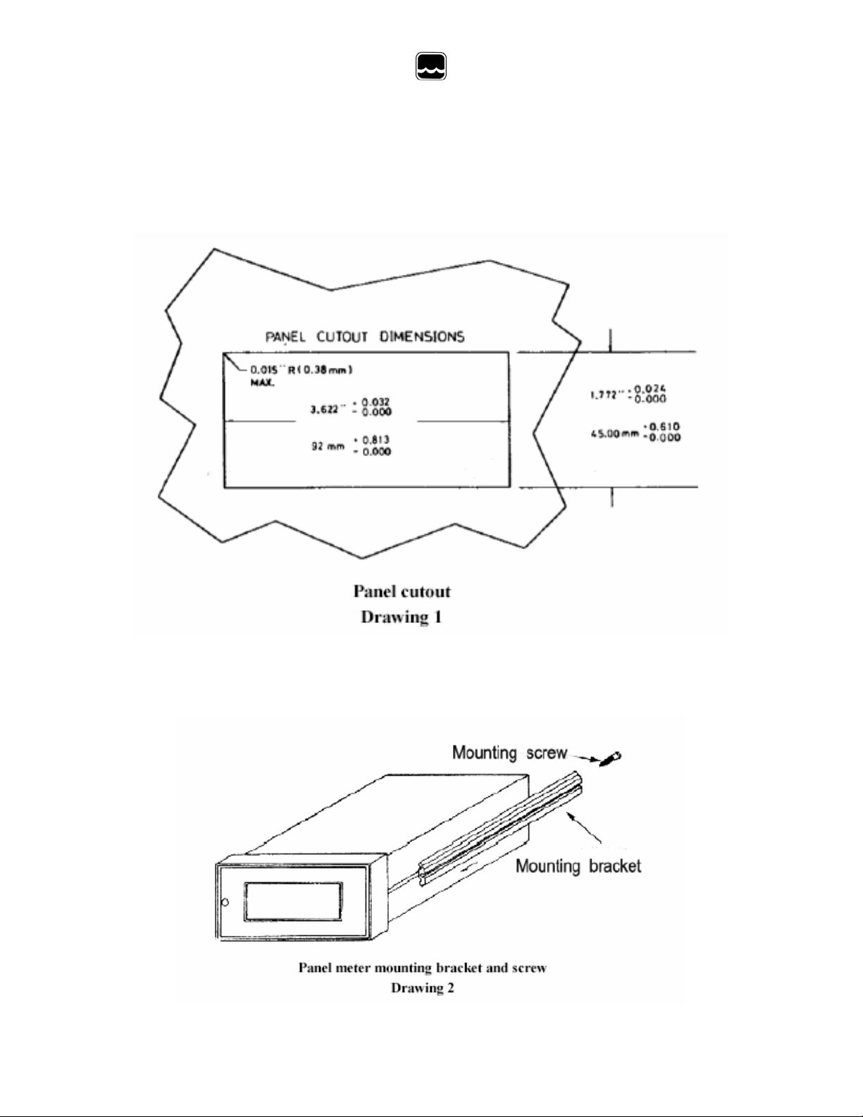
III) Mounting Procedure
a) Make a cutout on any panel, with a thickness of 1/16 in. (1.5mm) to 3/8 in. (9.5
mm). Refer to Drawing 1.
b) Rem ove the mounting brackets assembly from the panel meter and insert the
panel meter into the cutout. Refer to Drawing 2.
- 4 -
Page 5

Global Water
800-876-1172 • globalw.com
c) Replace the mounting brackets assembly onto the panel meter and fasten the
mounting screws to secure the panel meter to the mounting panel. Refer to
Drawing 3.
IV) Rear Panel Connection Diagram
Refer to Drawing 4 (page 6.)
a) Connect the AC power leads to the terminal strip on the rear of the instrument.
The model 3101 can be used with 115 VAC or230VAC, 50/60 Hz.
b) Connect the two conductivity cell leads from the Cat. No.105 probe to the CELL
terminals on the rear of the instruments.
c) Connect the two temperature compensation leads from the Cat.No.105 probe to
the TH terminals on the rear of the instrument.
d) Connect the load of the high set point relay to the NO and Com of the HIGH SET
terminals on the rear panel.
e) Connect the load of the low set point relay to the NO and COM of the LOW SET
terminals on the rear panel.
V) Earth Ground
a) The EARTH terminal on the rear panel must be connected to ground via third lead
of the power line. Refer to Drawing 4 (Page 6.)
b) If the third lead is not available, use a separate lead to connect the Earth terminal
to ground.
c) This safety procedure must be observed to avoid possible human injury and
damage to devices connected or in contact with the instrument in the event of
instrument failure.
- 5 -
Page 6

Global Water
800-876-1172 • globalw.com
VI) Measurement range select
a) Loosen the one earth ground screw on the rear of the instrument. Refer to
Drawing 4. Loosen the screw on the front panel. Refer to Drawing 5 (page 7.)
b) Push the rear panel toward the front of the instrument to expose the internal DIP
switch .Set the DIP switch according to Table 1 for the desired measure and
control range.
c) Push the front panel back into the metal case and tighten the screw on the front
panel. Replace the screw on the rear panel.
Range
0 to 200 mS/cm
0 to 99.9 mS/cm
0 to 9.99 mS/cm
0 to 999 µS/cm
Note: 1=ON 0=OFF
- 6 -
Page 7

Global Water
800-876-1172 • globalw.com
Dip switch position Table 1
1 2 3 4 5 6 7 8 9
0 1 0 0 1 0 1 0 0
0 0 1 0 1 0 1 1 0
0 0 1 0 0 1 1 0 1
1 0 1 1 0 0 0 0 0
VII) Analog Voltage Output
a) The analog voltage output can be used to interface with other instrument, such as
recorder, printer, computer-interfacing peripherals, etc.
Output voltage: 1 mV per LSD, least significant digit.
0 mV for 000 display, regardless of the position of the decimal point.
The following rule must be observed in order to avoid reading inaccuracies or
possible damage to the instrument.
1. If the sample under test is in contact with earth grounded, the interface
device's circuit common must not be connected to earth ground.
2. The input impedance of the interface device must be greater than 1 K
Ohm.
3. Make sure that the AC line voltage is never accidentally connected to the
analog output.
- 7 -
Page 8

Global Water
800-876-1172 • globalw.com
VIII) Controller Set
a) Press the HI(LO) set switch on the front panel. Refer to Drawing 5 (Page 7.) The
instrument will indicate the conductivity value of the set point.
b) Adjust the HI(LO) set control on the front panel for the desired set point
conductivity value.
c) Release the HI(LO) set switch, the meter will again indicates the measured
conductivity value.
IX) Controller relay output format
a) The HI set control and LO set control each activates an independent ON/OFF
relay.
The load to the relays should be always connected to the ON and COM terminals.
The relay load should not exceed the rating of 8 A at 115 V and 4A at 230V .The
relay rating is for resistive load only.
b) The LED in the set point switch will be ON when the relay is energized. Refer to
Drawing 5 (Page 7.) Power is delivered to the load through the ON and COM
terminals of the relay.
1. High set point
The LED will be ON and the relay will be energized when the
conductivity value is above the HI SET point value.
2. Low set point
The LED will be ON and the relay will be energized when the
conductivity value is less than the LO SET point value.
X) Relay Dead Band (Hysteresis)
a) The DEAD BAND of the ON/OFF relays are factory set to ±5 LSD, least
significant, digit, of the displayed value. DEAD BAND is defined as the process
value band where the relay is actuate upon rising process value and de-actuated
upon failing process value. Refer to Drawing 6 (page 9.) The DEAD BAND is
used to suppress relay chattering when excessive noise is picked up from the
measurement system.
- 8 -
Page 9

Global Water
800-876-1172 • globalw.com
XI) Temperature compensation
a) The instrument is calibrated to a temperature coefficient of 2% per degree C over
the measurement temperature range of 5 to 55°C. Temperature compensation
refers all measure values to 25°C.
XII) Temperature compensation thermistor
a) External resistive can be used to perform temp. compensation, when conductivity
probes other than the Cat. No. 105 probe is used. Refer to following table. The
replacement conductivity probe must be made of platinum element and a nominal
cell constant of 1.0.
Temp in °C Resistance in Kohms
5 22.05
10 17.96
15 14.68
20 12.09
25 10.00
30 8.313
35 6.941
40 5.828
45 4.912
50 4.161
55 3.57
- 9 -
Page 10

Global Water
800-876-1172 • globalw.com
XIII) Cell constant
a) The model 3101 is designed for use with conductivity probes of 1.0 cell constant.
XIV) Calibration using standard solutions
a) Rinse the conductivity probe with de-ionized water or the standard solution.
b) Immerse the conductivity probe in the standard solution .Choose the standard
solution closet to the value of the sample solution .Refer to table 2.
c) Set the Cell adjust control on the front panel for the meter to display the value of
the standard solution.
d) The instrument is calibrated and ready for measurements.
Standard solution Instrument range Meter display value
A 0 to 999 µS/cm 147
B 0 to 9.99 mS/cm 1.41
C 0 to 99.9 mS/cm 12.9
D 0 to 200 mS/cm 111
XV) Preparation of standard solutions
a) Solution A- dilute 100ml of solution B to 1000ml with deionized water.
b) Solution B- weigh out (in air) 0.7440g research grade KCL and to 1000ml with
deionized water.
c) Solution C- weigh out (in air) 7.4365g research grade KCL and to 1000ml with
deionized water.
d) Solution D- weigh out (in air) 74.2640g research grade KCL and to 1000ml with
deionized water.
XVI) Conductivity measurement
a) The instrument must be calibrated with standard solution before use, as the cell
content is slightly different for each conductivity probe.
b) Rinse the conductivity probe with de-ionized water or the standard solution.
Table 2
- 10 -
Page 11

Global Water
800-876-1172 • globalw.com
c) Immerse the conductivity probe in the sample to be measured .The instrument
will indicate the conductivity value of the sample recorder referred to 25°C.
XVII) Trouble Shooting
Other issues
a) Call us for tech support: 800-876-1172 or 916-638-3429 (many problems can be
solved over the phone). Fax: 916-638-3270 or Email: globalw@globalw.com.
Be prepared to describe the problem you are experiencing including specific
details of the application and installation and any additional pertinent information.
b) In the event that the equipment needs to be returned to the factory for any reason,
please call to obtain an RMA# (Return Material authorization). Do not return
items without an RMA# displayed on the outside of the package.
Clean and decontaminate the 3101 Conductivity Controller if necessary.
Include a written statement describing the problems.
Send the package with shipping prepaid to our factory address. Insure your
shipment, as the warranty does not cover damage incurred during transit.
c) When calling for tech support, please have the following information ready;
1. Model #.
2. Unit serial number.
3. P.O.# the equipment was purchased on.
4. Our sales number or the invoice number.
5. Repair instructions and/or specific problems relating to the product.
XVIII) Warranty
a) Global Water Instrumentation, Inc. warrants that its products are free from defects
in material and workmanship under normal use and service for a period of one
year from date of shipment from factory. Global Water’s obligations under this
warranty are limited to, at Global Water’s option: (I) replacing or (II) repairing;
any products determined to be defective. In no case shall Global Water’s liability
exceed the products original purchase price. This warranty does not apply to any
equipment that has been repaired or altered, except by Global Water
Instrumentation, Inc., or which has been subject to misuse, negligence, or
accident. It is expressly agreed that this warranty will be in lieu of all warranties
of fitness and in lieu of the warranty of merchantability.
The warranty begins on the date of your invoice.
- 11 -
 Loading...