

Page 1
3017M Quick Start Guide
DPD CHLORINE ANALYZER
Quick Start Guide
330028
Page 2
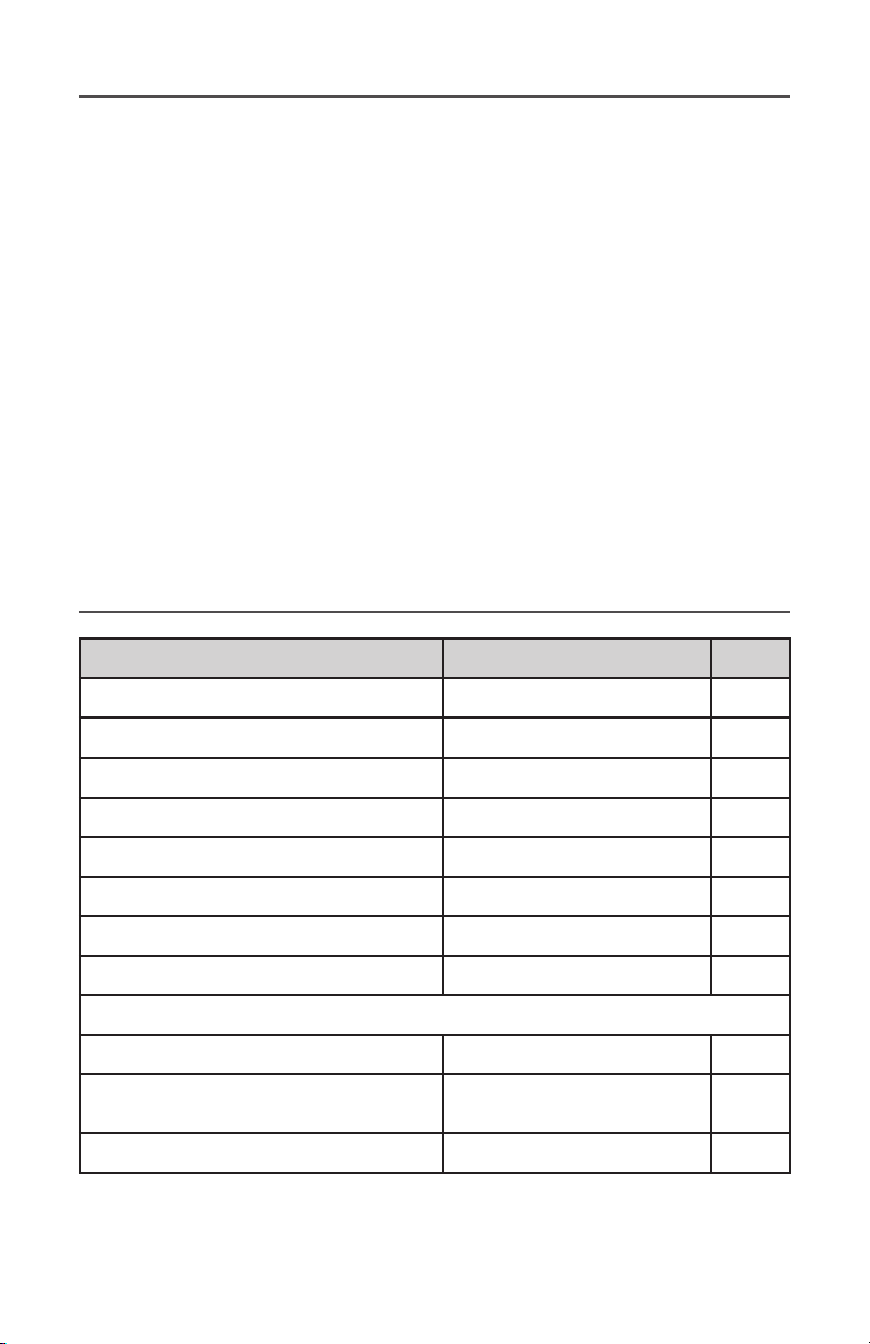
Table of Contents
1 What’s Included?
2 Inspection
3 Materials Required
4 Mounting Instructions
6 Reagent Preparation
7 Sample Inlet Device - Overview, Warnings & Mounting Location
9 Sample Inlet Device - Step-by-Step Installation Procedure
11 Sample Pump Tube Installation
12 Reagent Tube Installation
13 Startup & Operation
What’s Included?
Item Part # Qty.
3017M Chlorine Analyzer 332266 1
Sample Pump Tube* 332405 1
Reagent Pump Tubes* 332268 2
Silicone Lubricant 331121
Reagent Bottle Cap Assembly* 332270 2
1/2” ID Drain Tube, 6 ft. 327112 1
1/8” OD Sample Inlet Tube, 3 ft. 147901 1
3017M Operators Manual 332100 1
Accessories that may be included:
Sample Inlet Device 327114 1
Kit - Total Chlorine Reagent or
Kit - Free Chlorine Reagent
Reagent Mixing Instructions 330030 1
330006
330007
*Installed on the 3017M
1
1
Page 3
Inspection
Remove the analyzer and Sample Inlet Device from the shipment boxes.
Inspect the shipment for any damage or missing parts. Contact YSI
Customer Support immediately to report any damage or discrepancies
with the shipment. Any questions should be directed to YSI Customer
Support at (800) 765-4974 or (937) 767-7241.
2
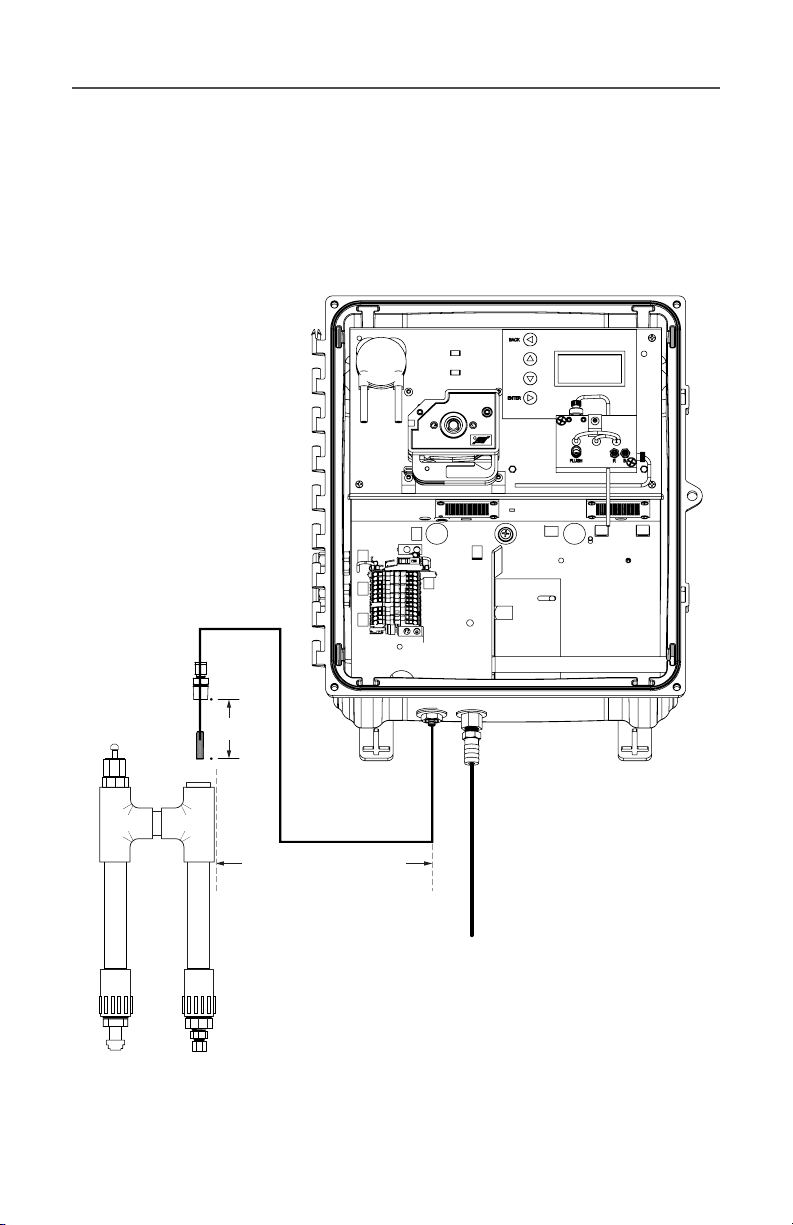
5”
1/2” ID Urethane tubing
As close as possible 1m
(3.28 ft) max.
Figure 1: YSI 3017M DPD Chlorine Analyzer and Sample Inlet
Device shown in the recommended installation configuration.
open to atmospheric drain
(item #327112)
Page 4
NOTE: Do not apply power to the unit until all of the
following steps have been completed.
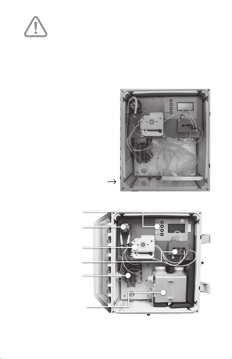
The 3017M was shipped from the factory as shown in Figure 2. It will
be necessary to attach the mounting tabs, mount the analyzer, mix the
reagents, position the sample pump tube, tension the reagent pump
tubes and connect the analyzer to the sample.
Materials Required
• #1 Phillips screwdriver
• 1/16” (or smaller)
flat-head screwdriver
• 3/8” drive ratchet
• 7/16” socket
• 7/16” wrench
• Scissors
• Rag or paper towels
Figure 2: The 3017M Chlorine Analyzer
as it is shipped from the factory
Display & Control
Sample Pump
Reagent Pump
Measuring Cell
I/O Terminal Block
1. Power
2. Communication
3
Reagents
Figure 3: 3017M Chlorine
Analyzer components
Page 5
Mounting Instructions
1. Attach the enclosure’s 4 mounting tabs to the back of the 3017M
using the flat head screws in the hardware kit.
2. Mount the 3017M in the desired location with user supplied
mounting hardware.
3. Install the Sample Inlet Device in its designated location (if
applicable). Below and to the left of the analyzer is an ideal position.
See Figure 1.
4. Power and RS 485/4 to 20 mA connections are made through the
cable glands that are supplied with the analyzer. The cable glands can
be found on the left-hand side of the analyzer.
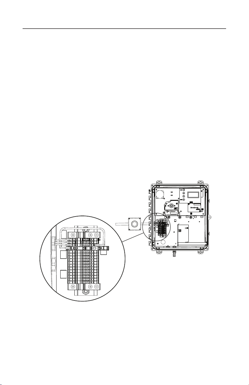
5. Wire the main power and any other signal or alarm connections.
6. The terminal block connectors are opened by pushing the 1/16”
screwdriver into the small, square opening adjacent to the opening
for the wire. See Figure 4.
External
Power Switch
(recommended)
4
1
2
3
4
5
6
7
8
9
10
11
12
13
14
15
16
Figure 4: 3017M terminal block and external power switch
(Wiring reference table on next page)
Page 6

Mounting Instructions, cont’d
Position Connection/Purpose Wire Color
1 AC Earth Green/Green Yellow
2 AC Neutral (Line 2) White/Blue
3 AC Line (Line 1) Black/Brown
4 Fusible Link (0.5A) Brown
5 RS 485-A White
6 RS 485-B Grey
7 RS 485 RTN Purple
8 4-20 mA (-) Blue
9 4-20 mA (+) Green
10 ALARM1 (NC) Yellow
11 ALARM1 (COM) Orange
12 ALARM1 (NO) Red
13 ALARM2 (NC) Brown
14 ALARM2 (COM) Black
15 ALARM2 (NO) Pink
16 SPARE ---
6. Attach the 1/2” ID drain tube to the barbed fitting on the bottom of
the analyzer. Refer to Figure 5.
7. Attach the 1/8” OD tubing to the sample inlet fitting (quick connect)
on the bottom of the analyzer and connect the other end to the
Sample Inlet Device or any other sample spot.
5
Page 7

Mounting Instructions, cont’d
1.736”
(44.08 cm)
2.988”
(75.88 cm)
3.475”
(88.26 cm)
Figure 5: 3017M plumbing connections, bottom view
Reagent Preparation
1. Refer to YSI document 330030 for preparation of the reagents.
2. Install a reagent bottle cap assembly (item #332270) to the reagent
containers.
3. Place the indicator reagent on the right-hand side of the enclosure
(closest to the wall of the enclosure).
4. Place the buffer next to it (left-hand side). Refer to Figure 7.
NOTE: Only high purity, chlorine-free water should be used for the
reagents. Deionized (DI) water, at a minimum, is acceptable.
6
Page 8

Sample Inlet Device - Overview
The Sample Inlet Device (part #327114, see Figure 6) is a simple, easy-
to-use device that serves as the interface between the sample tap and
the 3017M Chlorine Analyzer. The Sample Inlet Device consists of
inlet and outlet ports, a 60-micron filter for filtration of fine particles, if
necessary, and a 20-psig pressure relief valve.
NOTE: The Sample Inlet Device is an optional accessory, and although
it can add great benefits to the 3017M platform, it is not a required
accessory. The following information pertains to the installation of the
Sample Inlet Device, if this doesn’t apply to your installation of the
3017M please skip to page 11.
Sample Inlet Device - Warnings
The selection of a representative sample is important for optimal
performance of the analyzer and analytical results. The sample must be
representative of the condition of the entire process. Erratic reading
will be realized if the sample is drawn from a location that is too close
to the point of chemical injection, if mixing is incomplete, or if the
chemical reaction is incomplete.
Install sample line taps into the side or center of larger process pipes
to minimize the chance of ingestion of sediment or air bubbles. A
tap projecting into the center of a pipe is an ideal location. Opaque
tubing is recommended if the tubing is exposed to sunlight in order to
prevent algae growth.
Sample Inlet Device - Mounting Location
The ideal location for the Sample Inlet Device is below the 3017M
Chlorine Analyzer and as close as practical to the 1/8-inch quickconnect fitting at the bottom of the analyzer. The installation location
of the Sample Inlet Device should not exceed 3.25 ft. (1 m) from
the analyzer. See Figure 1.
7
Page 9

1/4” NPT to 1/8” TUBE
BRASS FITTING
POLY FILTER 60U
SAMPLE INLET
DEVICE ASSEMBLY
INSERT POLY FILTER ON END
OF 1/8” TUBE TO MIDDLE OF
CLEAR INLET TUBE
1/8” X 1X16” ID
TEFLON TUBING
8
1/2” ID URETHANE
TUBING TO DRAIN
1/2” TO 1/4” PVC
REDUCING BUSHING
1/4” TO 1/4” TUBE
BRASS FITTING
1/4” POLY TUBING FROM
FLOW PRESSURE REGULATED
SAMPLE STREAM TAP
Figure 6: YSI 3017M Sample Inlet Device
Page 10

Sample Inlet Device - Step-by-Step Installation Procedure
Mounting - Secure the Sample Inlet Device to the wall,
1
2
panel, or other structure. A Sample Inlet Device mounting
clip is supplied with the Sample Inlet Device kit. Other
mounting options can be applied to the Sample Inlet Device
but are not supplied by the manufacturer.
Plumbing - Push the 1/4-inch OD tubing into the inlet fitting.
A stop will be felt when the tubing is properly seated in the
fitting. Repeat this process for the outlet fitting. Route the
outlet tubing to an atmospheric drain or sump.
Note: In normal flow applications, the inlet to the Sample
Inlet Device can be on either side. In low flow and/or high
particulate applications make sure the inlet is on the same
side as the sample pick-up line.
1. Gently unscrew the 1/8-inch NPT tube fitting at the top
of the Sample Inlet Device. This fitting has a Teflon® twopiece ferrule. Be sure not to lose the front and back ferrule
when taking apart this fitting. Insert the sample pick-up line
into the fitting.
9
2. Attach the 60 micron filter to the end of the sample
pick-up line, if necessary. It is recommended that the 60
micron filter is used in any application that contains or has
the potential to contain any particulate matter within the
sample.
3. Thread the NPT tube fitting into the Sample Inlet
Device. Position the sample pick-up line/filter approximately
mid-way in the Sample Inlet Device. To secure the sample
pick up line in place gently hand tighten (do not overtighten)
the 1/8-inch nut on the NPT tube fitting.
Page 11

Front ferrule
Back ferrule
NPT tube
fitting
3
1/8” nut
Sample inlet assembly
60 micron filter
Testing - Apply sample to the system and check for leaks.
Ensure that the sample from the outlet of the Sample Inlet
Device is flowing freely to the drain.
4
10
Installation of the Sample Inlet Device is complete.
Page 12

Sample Pump Tube Installation
1. Refer to Figure 7.
2. Remove the cover from the sample pump by gently pulling on the
bottom of the pump cover.
3. Position the tube so that the barbed fittings on each end are even.
They will be adjusted in a later step.
4. Locate the package of silicone grease and cut a small opening across
one corner of the package.
5. Apply a thin layer of the silicone grease to the section of the tube that
will mount on the roller in the pump. A small bead of approximately
3 mm in diameter should be sufficient. Spread the grease along the
section of the tube that will contact the pump tube rollers. Do not
apply the grease in excess. There is sufficient grease in the startup kit
for multiple pump tube installations. Remove any excess with a rag or
paper towel.
6. Hold the pump tube over the roller, and gently push the roller onto
the drive shaft of the pump motor.
7. Refer to Figure 8.
8. Snap the cover into place so that the roller stays in place.
9. Gently position the sample pump to remove slack on each tube.
11
Figure 7: Sample pump
shown with cover off
Figure 8: Completed pump tube installation
Page 13

Reagent Tube Installation
1. Refer to Figure 9.
2. Tension the reagent pump tubes by depressing the tensioning levers
downward three “clicks”.
3. This completes the installation of the reagent pump tubes.
NOTE: Do not overtighten the reagent pump tubes. This will lead to
permanent failure.
12
Figure 9: Tension lever - complete reagent
pump tube installation
Page 14

Startup and Operation
1. Ensure that the main power and the desired aqueous sample are
available to the instrument.
2. Close the fusible link on the terminal block.
3. The analyzer will power on and initiate a self-test. Once the self-test
is completed, the analyzer will come to SHUTDOWN mode. Power is
not removed from the analyzer.
BACK
Chlorine 3017M
Chlorine 0.00 mg/L
STATUS: SHUTDOWN
MENU
ENTER
4. Using the UP or DOWN button, navigate to the PRIME function and
press ENTER.
5. The sample pump and reagent pump will turn at a higher than normal
speed to fill the sample and reagent lines with liquid.
6. Observe the outlet (waste) line of the measuring cell.
7. If chlorine is present in the water, the water at the outlet of the
measuring cell should turn magenta when the sample and reagents
begin to mix in
the flowcell.
8. When no bubbles are present at the outlet of the measuring cell , the
lines are fully primed with liquid.
9. Using the UP or DOWN button, select STANDBY and ENTER.
10. When you are ready for routine sample analysis, select STARTUP
and ENTER.
13
Page 15

Startup and Operation, cont’d
11. The STARTUP sequence consists of the following steps and will take
several minutes:
1. PRIME: The sample and reagent pumps will turn at a high
speed to prime the lines with liquid.
2. RINSE: The reagent pump will stop, and the sample pump will
continue to turn and rinse the flowcell with sample.
3. AUTOGAIN SET: The zero point, sample without reagent, is
determined.
4. RUN: The sample pump will return to the speed for normal
operation.
5. INJECT REAGENT: The reagent pump will start and run for the
predetermined amount of time.
6. INTEGRATE: The analyzer measures the absorption of light
that corresponds to the concentration of the sample flowing
through the flowcell.
7. CALCULATE VALUE: The concentration of the sample is
calculated against the calibration curve stored on
the analyzer.
8. DISPLAY VALUE: The concentration of the sample is displayed
on the screen.
12. The analyzer should cycle for 15 – 20 minutes (6 – 8 cycles) before
making comparisons with reference methods and adjusting the
analyzer output.
14
Page 16

1) The tissue in plants that brings water upward from the roots;
2) a leading global water technology company.
We’re a global team unified in a common purpose: creating advanced
technology solutions to the world’s water challenges. Developing new
technologies that will improve the way water is used, conserved, and
re-used in the future is central to our work. Our products and services
move, treat, analyze, monitor and return water to the environment, in
public utility, industrial, residential and commercial building services
settings. Xylem also provides a leading portfolio of smart metering,
network technologies and advanced analytics solutions for water,
electric and gas utilities. In more than 150 countries, we have strong,
long-standing relationships with customers who know us for our
powerful combination of leading product brands and applications
expertise with a strong focus on developing comprehensive,
sustainable solutions.
For more information on how Xylem can help you,
go to www.xylem.com
QUICK START GUIDE 330028
YSI, a Xylem brand
1725 Brannum Lane
Yellow Springs, OH 45387
+1.937.767.7241
info@ysi.com
YSI.com
© 2021 Xylem, Inc. 330028 04/21
YSI.com/3017M
 Loading...