

Page 1

INSTRUCTION MANUAL
19-001-350R2
THIS MANUAL IS FOR TECHNICIAN USE ONLY
PACE™ Integrated Pump Controller
Human Machine Interface (HMI)
for the Silent Storm VFD Pumping System
TECHNICIAN GUIDE
Page 2

2
Acknowledgements
All materials ©2013 by Flowtronex, A Xylem company.
Flowtronex© is a registered trademark of Flowtronex a Xylem Company.
All rights reserved. No parts of this work may be reproduced in any form or by any means - graphic,
electronic, or mechanical, including photocopying, recording, taping, or information storage and retrieval
systems - without the written permission of the publisher.
Products that are referred to in this document may be either trademarks and/or registered trademarks of
the respective owners. The publisher and the author make no claim to these trademarks. These include
Microsoft, Windows, Windows NT, ActiveX that are either registered trademarks or trademarks of Microsoft
Corporation in the United States and/or other countries. ©2013 Microsoft Corporation. All rights reserved.
WHILE EVERY PRECAUTION HAS BEEN TAKEN IN THE PREPARATION OF THIS DOCUMENT, THE
PUBLISHER AND THE AUTHOR ASSUME NO RESPONSIBILITY FOR ERRORS OR OMISSIONS, OR
FOR DAMAGES RESULTING FROM THE USE OF INFORMATION CONTAINED IN THIS DOCUMENT
OR FROM THE USE OF PROGRAMS AND SOURCE CODE THAT MAY ACCOMPANY IT. IN NO EVENT
SHALL THE PUBLISHER AND THE AUTHOR BE LIABLE FOR ANY LOSS OF PROFIT OR ANY OTHER
COMMERCIAL DAMAGE CAUSED OR ALLEGED TO HAVE BEEN CAUSED DIRECTLY OR
INDIRECTLY BY THIS DOCUMENT.
Page 3

3
TABLE OF CONTENTS
ACKNOWLEDGEMENTS ......................................... 2
ACKNOWLEDGEMENTS ......................................... 2
INTRODUCTION ....................................................... 6
HMI OVERVIEW ........................................................ 6
TYPICAL PUMPING OPERATION ................... 7
TOUCH-SCREEN PANEL OPERATION .................. 7
ENHANCED KEY PAD ...................................... 8
BASIC SCREEN LAYOUT ........................................ 8
USER TYPES ............................................................ 8
OPERATION MENU .................................................. 9
SYSTEM VIEW & TRENDS .............................. 9
Configure Period Screen ....................................... 9
Configuring the Data Shown on the Screen ........ 10
FLOW TOTALS ............................................... 11
PUMP STATUS ............................................... 11
AUXILIARY EQUIPMENT STATUS ................ 12
Booster Pumps: ................................................... 12
Automated Lake (ALS) Monitoring Screen .......... 12
Lake Level Controls Monitoring Screen .............. 12
Lake Level/Transfer/Timed Pump Monitoring Screen:
............................................................................ 13
Timed Pump Monitoring Screen (Non-Integrated
Only) .................................................................... 13
Simple Filters Monitoring Screen ........................ 13
Scanner Filters Monitoring Screen ...................... 13
Solid Separators Monitoring Screen ................... 14
ALARMS .......................................................... 14
EVENTS .......................................................... 14
LOCKOUT VIEW ............................................. 15
KWH RECORDS ............................................. 15
SETUP MENU ......................................................... 16
USER SETUP ................................................. 16
Set/Sync HMI-PLC Date/Time ............................ 16
Lamp Test ........................................................... 17
LOCKOUT SETUP .......................................... 17
SECURITY SETUP ......................................... 17
SYSTEM SETUP ............................................. 18
Job Information ................................................... 18
Basic Pump Information ...................................... 18
Zone Configuration .............................................. 18
Pump Configuration ............................................ 19
Alarm Setup ........................................................ 19
Combo Options ................................................... 19
FIELD SETUP ................................................. 20
PID Tuning .......................................................... 20
OPA Enable ........................................................ 22
Current dP/dT values are shown to assist in tuning
the dP/dT system. ............................................... 22
Combos ............................................................... 22
Combo Pumps .................................................... 23
AUXILIARY SETUP ......................................... 23
Booster Setup ..................................................... 24
ALS Setup ........................................................... 24
Lake Level Controls Setup .................................. 24
Lake Level Controls Setup (Non-Integrated only)26
Timed Pump Setup (Non-Integrated only) .......... 26
Simple Filters Setup ............................................ 26
Simple Filters Setup ............................................ 26
Scanners Filter Setup ......................................... 27
Options Setup ..................................................... 27
VFD Bypass ........................................................ 27
Analog Scaling .................................................... 27
ActiveX and IP Updates ...................................... 28
WinCE Remote Access ....................................... 28
Alternate SP ........................................................ 28
Database Settings ............................................... 29
SETUP/CONFIGURATION FILE .............................. 30
EXIT APPLICATION ................................................ 31
NETWORKING AND REMOTE ACCESS ................ 31
Remote Software Log In ..................................... 31
WEB REPORTS ....................................................... 31
Log on to Web Reports ....................................... 31
Web Reports Menu ............................................. 32
Trend View .......................................................... 32
Alarms Report ..................................................... 32
Historical Report ................................................. 33
Usage Report ...................................................... 33
Smart Phone and PDA access: .......................... 33
APPENDIX A–GLOSSARY OF TERMS .................. 34
APPENDIX B ─ PANEL SWITCH SETTINGS ......... 37
APPENDIX D–TYPICAL ALARMS CONFIGURATION
.................................................................................. 39
APPENDIX E – DEFAULT IP ADDRESSES FOR
AUXILIARY DEVICES .............................................. 40
APPENDIX F – EMAIL TROUBLESHOOTING ....... 41
DETERMINING THE IP ADDRESS OF THE
SMTP SERVER ............................................... 41
TROUBLESHOOTING GENERAL EMAIL
FAILURES ....................................................... 43
Troubleshooting Email SET Failures .................. 43
Troubleshooting Email Send Failures ................. 44
APPENDIX G: COMPUTER SETUP AND
DETERMINING THE IP ADDRESS OF YOUR PUMP
STATION .................................................................. 46
DETERMINING THE IP ADDRESS: ................ 48
APPENDIX H – GENERAL NETWORKING AND
ROUTER CONFIGURATION DISCUSSION: ........... 50
NOTE: The information contained in this book
is intended to assist operating personnel by
providing information about the characteristics
of the purchased equipment. It does not relieve
the user of their responsibility of using accepted
engineering practices in the installation, operation,
and maintenance of this equipment.
Page 4

4
For additional questions, contact:
XYLEM FLOWTRONEX
8:00 AM to 5:00 PM Central time (800) 786-7480 x3
5:00 PM to 8:00 AM Central time
After Hours technician for emergency assistance:
(214) 454-5768
support@flowtronex.com
TABLE OF FIGURES
Figure 1: Basic Operation ....................................... 7
Figure 2: Connection for USB Keyboard (c). .......... 7
Figure 3: Enhanced Key Pad .................................. 8
Figure 4: Basic Screen Layout ................................ 8
Figure 5: Log in Screen ........................................... 9
Figure 6: Operation Menu ....................................... 9
Figure 7: Trends Screen ......................................... 9
Figure 8: Configure Period .................................... 10
Figure 9: Configure Data ....................................... 10
Figure 10: Technical Overview ............................. 10
Figure 11: Combo Information .............................. 10
Figure 12: Combo Information .............................. 11
Figure 13: Flow Totals, Overview ......................... 11
Figure 14: Flow Totals, Daily Flows ...................... 11
Figure 15: Flow Totals, Weekly Flows .................. 11
Figure 16: Flow Totals Monthly Flows .................. 11
Figure 17: Flow Totals, Yearly Flows .................... 11
Figure 18: Animated Pump Status ........................ 12
Figure 19: Individual Pump Stats .......................... 12
Figure 20: Booster Monitoring Screen .................. 12
Figure 21: ALS Monitoring Screen ........................ 12
Figure 22: Lake Level Controls Monitoring Screen13
Figure 23: Timed Pump Monitoring Screen .......... 13
Figure 24: Simple Filters Monitoring Screen ......... 13
Figure 25: Scanner Filter Monitoring Screen ........ 14
Figure 26: Solid Filter Monitoring Screen .............. 14
Figure 27: Alarms Screen ..................................... 14
Figure 28: Events Screen ..................................... 15
Figure 29: Lockout View Screen ........................... 15
Figure 30: KWH Records, Overview ..................... 15
Figure 31: KWH Records, Daily Usage ................. 15
Figure 32: KWH Records, Weekly Usage ............. 15
Figure 33: KWH Records, Monthly Usage ............ 16
Figure 34: KWH Records, Yearly Usage .............. 16
Figure 35: Setup Menu ......................................... 16
Figure 36: User Setup Menu ................................. 16
Figure 37: Set/Sync HMI-PLC Date/Time ............. 17
Figure 38: Individual Lockout Setup ...................... 17
Figure 39: Parameter Tab in Lockout Setup ........ 17
Figure 40: Security Setup ..................................... 18
Figure 41: Job Information .................................... 18
Figure 42: Basic Pump Information ....................... 18
Figure 43: Zone Configuration .............................. 18
Figure 44: Pump Configuration ............................. 19
Figure 45: Alarm Setup ......................................... 19
Figure 46: Combo Options .................................... 19
Figure 47: PID Settings ......................................... 20
Figure 48: PID Settings ......................................... 20
Figure 49: OPA, Ramp Up and Dp/Dt control ...... 22
Figure 50: Combos ............................................... 23
Figure 51: Combo Pumps .................................... 23
Figure 52: Auxiliary Equipment Setup .................. 24
Figure 53: Booster Setup ..................................... 24
Figure 54: ALS Setup ........................................... 24
Figure 55: Lake Level Controls Setup .................. 25
Figure 56: Level/Timed pump configuration ......... 25
Figure 57: Integrated Timed Pump configuration . 26
Figure 58: Lake Level Controls Setup .................. 26
Figure 59: Timed Pump Setup ............................. 26
Figure 60: Simple Filters Setup ............................ 27
Figure 61: Scanners Filter Setup ......................... 27
Figure 62: Options Setup Menu ........................... 27
Figure 63: VFD Bypass ........................................ 27
Figure 64: Analog Scaling .................................... 28
Figure 65: ActiveX and IP Updates ...................... 28
Figure 66: WinCE Remote Access ....................... 28
Figure 67: Alternate SP ........................................ 28
Figure 68: Pressure SP ........................................ 29
Figure 69: Fertigation SP ..................................... 29
Figure 70: Database Settings ............................... 29
Figure 71: Email Settings ..................................... 30
Figure 72: Setup / Configuration File ................... 31
Figure 73: Exit App Warning ................................ 31
Figure 74: Web Reports Menu ............................. 32
Figure 75: Trends View ........................................ 32
Figure 76: Alarms & Events ................................. 33
Figure 77: Historical Report ................................. 33
Figure 78: Usage Report ...................................... 33
Figure 79: Computer Setup Options .................... 46
Page 5

WARRANTY INFORMATION
Company warrants title to the product(s) and, except as noted below with respect to items not of Company’s
Manufacturer, also warrants the product(s) on date on shipment to Purchaser, to be of the kind and quality
described herein, and free of defects in workmanship and material.
THIS WARRANTY IS EXPRESSLY IN LIEU OF ALL OTHER WARRANTIES, INCLUDING BUT NOT
LIMITED TO IMPLIED WARRANTIES OF MECHANTABILITY AND FITNESS, AND CONSTITUTES THE
ONLY WARRANTY OF COMPANY WITH RESPECT TO THE PRODUCT(S).
If within one year from date of initial operation, but nor more than eighteen months from date of shipment by
Company of any item of product(s), Purchaser discovers that such item was not as warranted above and
promptly notifies Company in writing thereof, Company shall remedy such non-conformance by, at Company
affected part of the product(s). Purchaser shall assume all responsibility and expense for removal,
reinstallation, and freight in connection with the foregoing remedies. The same obligations and conditions shal
xtend to replacement parts furnished by Company hereunder. Company shall have the right of disposal of
e
ts replaced by it.
par
ANY
SEPARATELY LISTED ITEM OF THE PRODUCT(S) WHICH IS NOT MANUFACTURED BY THE
COMPANY IS NOT WARRANTED BY COMPANY and shall be covered only the express warrant, if any, of the
manufacturer thereof.
l
THI
S STATES PURCHASER’S EXCLUSIVE REMEDY AGAINST COMPANY AND ITS SUPPLIERS
RELATING TO THE PRODUCT(S), WHETHER IN CONTRACT OR IN TORT OR UNDER ANY OTHER
LEGAL THEORY, AND WHETHER ARISING OUT OF WARRANTIES, REPRESENTATIONS,
INSTRUCTIONS, INSTALLATIONS OR DEFECTS FROM ANY CAUSE. Company and its suppliers shall have
obligation as to any product which has been improperly stored and handled, or which has not been operated
no
maintained according to instructions in Company or supplier furnished manuals.
or
5
Page 6

6
Introduction
This manual assumes that the reader has used and
understands basic Internet browser operation and
has used a Microsoft© Windows Operating System
GUI (Graphical User Interface), such as Windows
2000©, Windows NT©, Windows ME©, or Windows
XP©. This device uses Windows CE-as an
operating system (OS). Windows CE© is a
component-based version of the Windows
operating system designed for embedded devices,
such as PDAs or touch-panel displays.
This manual also assumes the user has some basic
knowledge of pumps and pumping systems.
Note: Button names are shown enclosed in square
brackets, such as [Button], whenever the actual key
or button graphic is not displayed.
The interface is displayed at the pumping station on
the HMI. Users make selections of the options and
enter data using a stylus or hands, and tapping
directly on the HMI’s color, touch-screen panel.
CAUTION: Equipment Damage Hazard
Only use a stylus or clean hands on the HMI
touch-panel device to access screens and
enter data. Use of any other tool, sharp object,
or contact with dirt or chemicals can cause
damage to the screen.
Failure to follow these instructions indicates a
potentially hazardous situation, which, if not
avoided, may result in equipment damage and
void any warranty.
CAUTION: Equipment Damage Hazard
To Clean the equipment:
Disconnect the equipment from any AC outlet,
use a clean damp cloth. Do not use liquid or
spray detergents for cleaning.
Failure to follow these instructions indicates a
potentially hazardous situation, which, if not
avoided, may result in equipment damage and
void any warranty.
HMI Overview
A web-based version of the application is
operational on the HMI and permits the user to
supervise the pumping station’s operation remotely
at any time from any internet-accessible computer.
The web-based screens are identical to the screens
viewed on the HMI. Web Reports can also be
viewed and printed by users who access the HMI
interface via the internet.
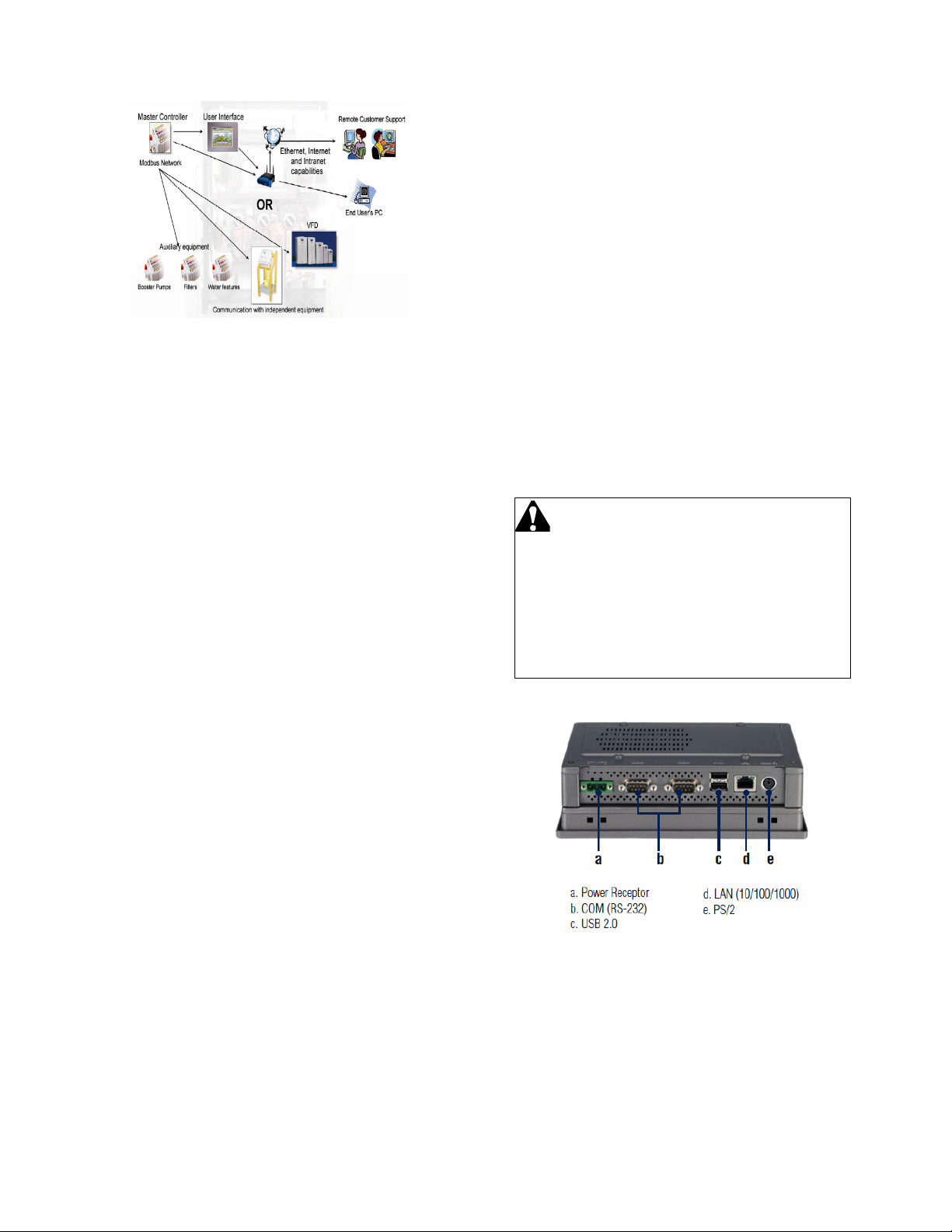
Data and information is exchanged with the
pumping station’s master controller, also called a
Programmable Logic Controller (PLC), located
physically in the NEMA 4 enclosure. The
communication exchanges are made over Ethernet.
A primary PLC is responsible for the real-time
control of the main pumps, while additional PLC(s)
are used to control auxiliary items. The HMI
provides a graphical user interface (GUI) which
permits the pumping station to be monitored, and
allows the controls or variables to be changed when
necessary. All monitoring and control information
can be sent to the pumping station remotely over
the Internet using the web-based version. This
basic communication between the remote user, the
HMI, and the pumping station is illustrated below.
This manual is written for Flownet Technicians and
is an introduction to the Flowtronex PACE HMI
uman Machine Interface). The HMI is a browser-
(H
based system which allows the user to interact with
the settings and reports of the pumping system. This
manual only covers the HMI aspect of the system.
Please see the Silent Storm VFD Pumping System
nstruction Manual for any questions not related to
I
he HMI.
t
The Flowtronex PACE is a modular and scalable
architecture that is used by the HMI (Human
hine Interface) to control a station’s pumps. It
Mac
o handles a variety of changing conditions using a
als
touch
panel display including normal operation,
operation with a v
including lake fi
fertilization injection (fer
operation with timed water features.
ariety of auxiliary equipment
ll controls, boosters, filtration, and/or
tigation) equipment, and
Page 7
7
Figure 1: Basic Operation
TYPICAL PUMPING OPERATION
Several common control variables including flow,
pressure, and level are used for operating an
automatic pumping system. Pump starts and stops
are based on the changes in these control
variables. A VFD (Variable Frequency Drive) is
used to regulate the speed of the lead pump,
replacing the function of a control valve. Pressure
recovery can be made smoothly, resulting in power
and cost savings.
When pressure is used as the key process variable,
the VFD pumping system constantly monitors
pressure to maintain the required demand. Pump
starts and stops are based on the changes in the
system pressure. For example, a pumping system
with one Pressure Maintenance (PM) pump and two
interchangeable main pumps may be grouped into
several different combos (combination of pumps)
that start or stop a specific pump, or a sequence of
pumps, according to defined setpoints.
Each combo has an individual start pressure that
references a setpoint pressure and a start delay
time. At very low demand, the PM pump maintains
the setpoint pressure. Once the demand becomes
greater than the PM pump can handle, the first
combo is activated. The lead pump in this combo is
controlled by the VFD. As demand increases,
additional lag pumps are added, or a different
combination of pumps is activated.
Other configurations are also possible. Consult your
Flownet Technician for proper operation of your
system.
Touch-Screen Panel Operation
This Flowtronex® Pace HMI device manual
describes the operation of the touch-panel display,
located on the enclosure door of the control unit of
the pumping station.
• Use a stylus to tap the buttons or fields
when using the touch-screen panel.
• Use the Enhanced Key Pad to enter
text or numbers in blank fields. Tap
and hold the stylus in a blank field to
open the Enhanced Key Pad pop up
screen.
• A USB Keyboard may also be used
instead of the Enhanced Key Pad.
Plug in the USB Keyboard into the
back of the display.
•
Danger: Electric Shock Hazard
Disconnect power before opening any
electrical enclosure. Any procedure requiring
opening an electrical enclosure must be
performed by qualified personnel only.
Failure to follow this guideline could result in
injury or death.
Figure 2: Connection for USB Keyboard (c).
Page 8
8
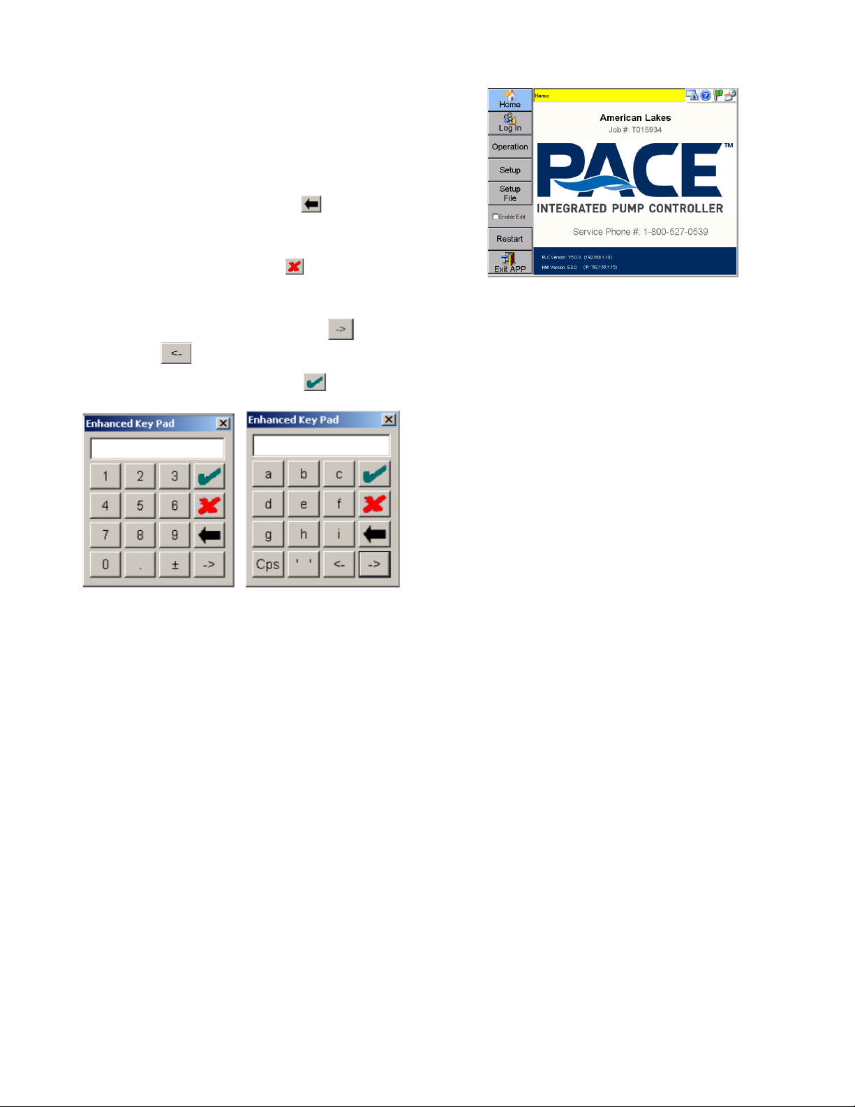
ENHANCED KEY PAD
Tap and hold the stylus in an editable field
(indicated by a white background) to open the
Enhanced Key Pad.
To use an Enhanced Keypad:
• To clear an entry, tap
to
backspace over entry.
• To close key pad without saving
entries, tap the red
on the key
pad.
• To switch between various alphabetic
and numeric key pads, tap
or
• To submit an entry tap
Figure 3: Enhanced Key Pad
Basic Screen Layout
The application uses a three-part structure for all
screens:
1. The Navigation Bar, located on the far left of
the screen, displays buttons to tap which will
navigate to other key areas of the application. The
content of the navigation bar changes depending on
what type of user is logged in.
2. The Header, located at the top center of the
screen, displays the screen name in the banner,
and (depending on the buttons selected on the
right) the date and time, or the pumping station’s
current flow and pressure readings.
NOTE: A flashing header is indicative of a system
fault.
3. The Main Window, located in the center of the
screen, displays one or more panes of information
about the pumping station. A grayed-out field in this
window is read-only. Other fields (with a few
exceptions) may be edited.
Figure 4: Basic Screen Layout
User Types
There are different types of users recognized by the
system:
Guest: Only operation screens are accessible in
view-only mode. Users are logged in as a Guest by
default.
Supervisor: End-User configurable setup and
operation screens are accessible. Supervisors must
log-in using a password.
Technician: All setup and operation screens are
accessible. Technicians must log-in using a
password. See the Technician Guide for additional
functions.
Note: Some values require you to set the “Enable
Edit” checkbox before you can change the values.
This is a precautionary measure intended to
prevent unwanted and accidental register value
writes. These values are available to technicians
only. Values normally accessed at the Supervisor
level or lower are not affected.
Touch Panel Log In
Tap [Log In] from the Home Screen.
The screen displays the current user type at the top
of the screen.
Page 9
9
Figure 5: Log in Screen
Default user is a Guest user. No log in is required.
To log in as a Technician, tap [Technician], and
then tap on the empty Password field to enter the
Technician password. Tap [OK] to log in or [Cancel]
to exit without logging in.
To obtain a Technician password, call Flowtronex
customer service and give them the APP code
displayed on the screen. Customer Service will then
give you a password corresponding to that APP
code which will remain active until the last day of
the current month.
After a password has expired, a new APP code
must be generated allowing you to get a new
password. See Security Setup for information on
how to generate an APP code.
NOTE: The web-based screens require an
immediate log-in as either a guest (no username or
password required), a Supervisor (username and
password are required) or a Technician (username
and password are required). The log-in screen will
be displayed first on the web-based application
only.
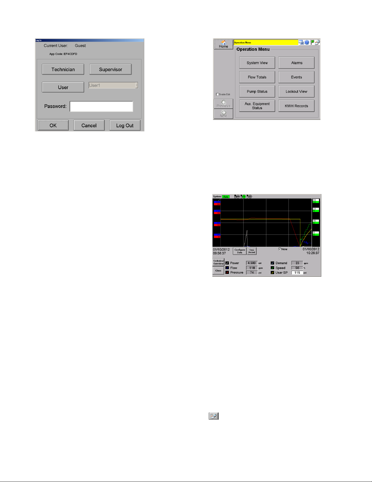
Operation Menu
Tap [Operation] from the Home screen.
The Operation Menu allows you to view the
pumping station’s operational trends (System
View), flow totals, pump and auxiliary equipment
status, alarms, events, lockouts, and power
consumption (KW Data).
Figure 6: Operation Menu
SYSTEM VIEW & TRENDS
Tap [System View] from the Operation menu.
System View accesses color-coded operational
trends or historical data for several system
variables such as flow, pressure, speed, and
setpoint.
Figure 7: Trends Screen
In the System View screen, a supervisor can
change the setpoint using the User SP field.
You can turn on and off logged channels on the
viewer by tapping the value at the bottom of the
screen.
Power readings may not be available on all
systems. Also on some systems a power reading of
0 will cause the Power display to disappear, and will
reappear when power readings return.
Demand is a function specific to interaction with
Lynx irrigation control systems and will only display
when this data is available from Lynx.
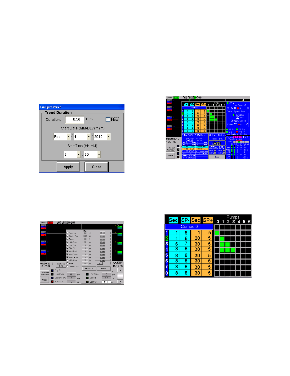
Configure Period Screen
Tap
from the System View menu.
The Configure Period screen allows you to set a
date and duration for viewing system information.
Page 10
10
The trends will be shown for the Duration value,
ending at the current time. When ‘Now’ is checked,
the system defaults to the current date and time.
If ‘Now’ has been checked, ‘Duration’ is the only
editable field.
For viewing historical data, uncheck ‘Now’.
Enter the start date and time, along with duration to
view data for desired time. Tap [Apply] to apply
changes or [Close] to cancel any changes.
NOTE: If ‘Now’ is left unchecked, the system does
not default back to the current date and time.
Figure 8: Configure Period
The trends graph may be enlarged for a better view
by tapping on it.
Configuring the Data Shown on the Screen
In technician mode, you can change the data the
screen shows. Click on “Configure Data”.
Figure 9: Configure Data
Check the box next to the data you want to show.
Not all data is available for all systems. Use the
slider bar on the right to adjust the graph scaling to
a value that makes it most comfortable to read.
100% means the graph scale is the same as the
analog scaling max value. 110% means the graph
scaling is 110% of the analog max scaling for the
channel. The exception here is the KW reading,
which is an absolute number because KW is read
directly, rather than scaled.
Click “Channels” to access the calibration screen
directly from the “Configure Data” screen.
This screen is accessible also from “Setup”>”Options Setup” and is discussed in detail in that
section.
Click “Technical Overview” to access details of
system operation. This is also accessible from the
“Green Flag” button on the header of other screens.
Figure 10: Technical Overview
This screen shows an overview of the configuration
of the station. Most data that is necessary for
tuning is shown, and the settings page for the
information can be accessed by touching the value.
For technicians, the fields available on this screen
should be fairly self-explanatory. However, some
fields can use some clarification:
Figure 11: Combo Information
This field shows, from left to right, the current
combo (highlighted), start time, psi below setpoint,
stop time and psi above setpoint to stop, for each
combo. To the right is a table detailing the pumps
to run in each combo. The example above shows
combo 1 consists of the PM Pump, Combo 2
consists of pump 1 (or any other single pump in the
same group), combo 3 is two main pumps, and
combo 3 is 3 main pumps.
Page 11
11
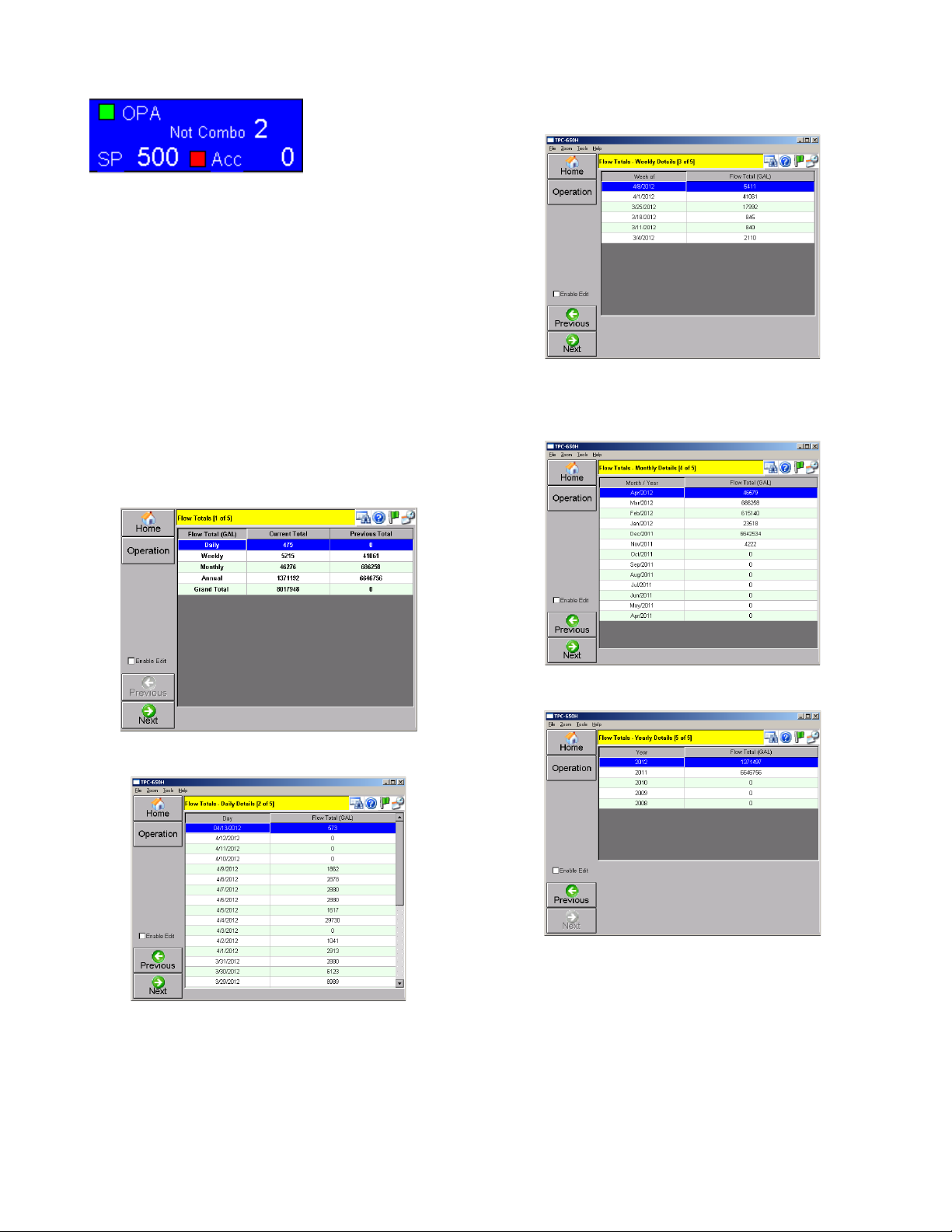
Figure 12: Combo Information
This shows the Overpressure accumulator settings.
“Not Combo” indicates that OPA will operate at any
combo level above 2. “Factor”
FLOW TOTALS
Tap [Flow Totals] from the Operation menu.
The totalized values (in GAL) for the daily, weekly,
monthly, and yearly flow are displayed in a tabular
format.
Tap [Next] to successively view the totals for each
day, week, month and year. Use the scroll bar to
move up and down or left and right.
Figure 13: Flow Totals, Overview
Figure 14: Flow Totals, Daily Flows
Figure 15: Flow Totals, Weekly Flows
Figure 16: Flow Totals Monthly Flows
Figure 17: Flow Totals, Yearly Flows
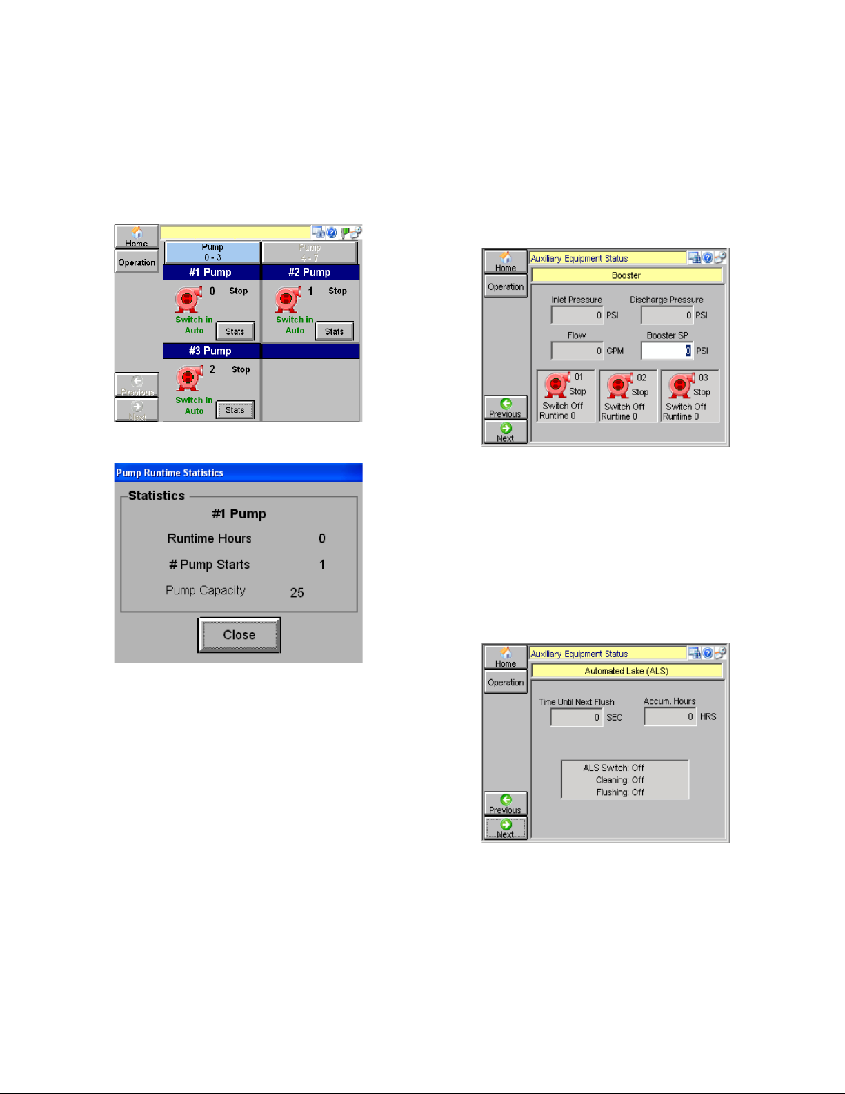
PUMP STATUS
Tap [Pump Status] from the Operation menu.
This screen displays an animated graphical display
of all the pumps in the system (up to eight pumps).
Page 12
12
Red, no animation: Stopped pump
Green, rotating center: Running pump
Yellow, flashing center: Fault condition
Individual pump stats (runtime hours, number of
starts, and pump capacity in GPM) can be viewed
by tapping [Stats] for each pump.
Figure 18: Animated Pump Status
Figure 19: Individual Pump Stats
AUXILIARY EQUIPMENT STATUS
Tap [Aux. Equipment Status] from the Operation
menu.
By tapping [Previous] or [Next], you can navigate
the status screens for each device that has been
set up.
NOTE: The screens described below will only be
displayed if they are applicable to the current
system.
Booster Pumps:
Booster Pumps are typically custom features and
the interface depends greatly on the specific site.
However some basic functionality is provided.
Booster pumps typically require an auxiliary PLC.
Up to three booster pumps may be monitored
simultaneously. All fields are read-only with the
exception of ‘Booster SP’. This pressure (PSI) value
remains same for all installed boosters, and is
generally higher than user defined SP.
Red, no animation: Stopped
Green, rotating center: Running
Yellow, flashing center: Fault condition
Tap [Next] to move to the next status screen.
Figure 20: Booster Monitoring Screen
Automated Lake (ALS) Monitoring Screen
This screen is used to monitor the Automated Lake
Screen. ‘Accum Hours’ is the total accumulated
time ALS has been running for. ‘ALS Switch’
denotes the position of ALS switch on the
enclosure. ‘Cleaning’ and ‘Flushing’ denote
if the respective cycles are on or off.
Tap [Next] to move to the next status screen.
Figure 21: ALS Monitoring Screen
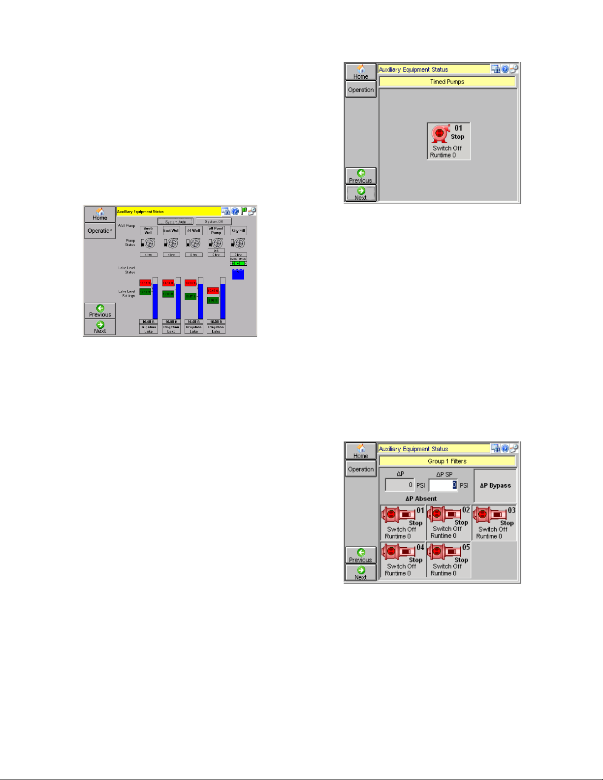
Lake Level Controls Monitoring Screen
A maximum of eight lake level controls can be
monitored/configured on this screen. Supervisor
access or higher is required to configure, but guest
level access can view the settings and status
information.
Page 13
13
The Lake Level Control screen shows the pump
number, whether the pump is currently on or off, if
the enclosure switch is set to on or off, and also
gives a pump’s runtime total in hours. If a well pump
is used, the well level is shown in feet in a read-only
field.
Tap [Next] to move to the next status screen.
Lake Level/Transfer/Timed Pump Monitoring
Screen:
Figure 22: Lake Level Controls Monitoring
Screen
This screen allows you to see the status of the Lake
Level/Timed pump control system at a glance.
Pump status (Off, Run, Fault), switch status
(On/Off), Level settings can be viewed/adjusted
(When logged in as Admin, Technician, or
Supervisor only), pump hours can be monitored,
Start/Duration times for timed pumps can be
monitored, lake levels and/or probe status (as
equipped).
Timed Pump Monitoring Screen (Non-Integrated
Only)
Currently, only one timed pump can be set up and
monitored on the Timed Pumps screen. The screen
is read only, and gives the pump number, status,
and the total run time in hours.
Red, no animation: Stopped
Green, rotating center: Running
Yellow, flashing center: Fault condition
Select [Next] to move to the next status screen.
Figure 23: Timed Pump Monitoring Screen
Simple Filters Monitoring Screen
Simple filters include Wye strainers and other filters
controlled by a simple on-off flush signal. This
screen will monitor all installed filters. ∆P denotes
differential pressure.
Red, no animation: Stopped
Green, rotating center: Running
Yellow, flashing center: Fault condition
A green colored graphic denotes that the filter is
flushing.
Other information displayed includes filter number,
run time (in hours), and whether the enclosure
switch is set to on or off.
Tap [Next] to move to the next status screen.
Figure 24: Simple Filters Monitoring Screen
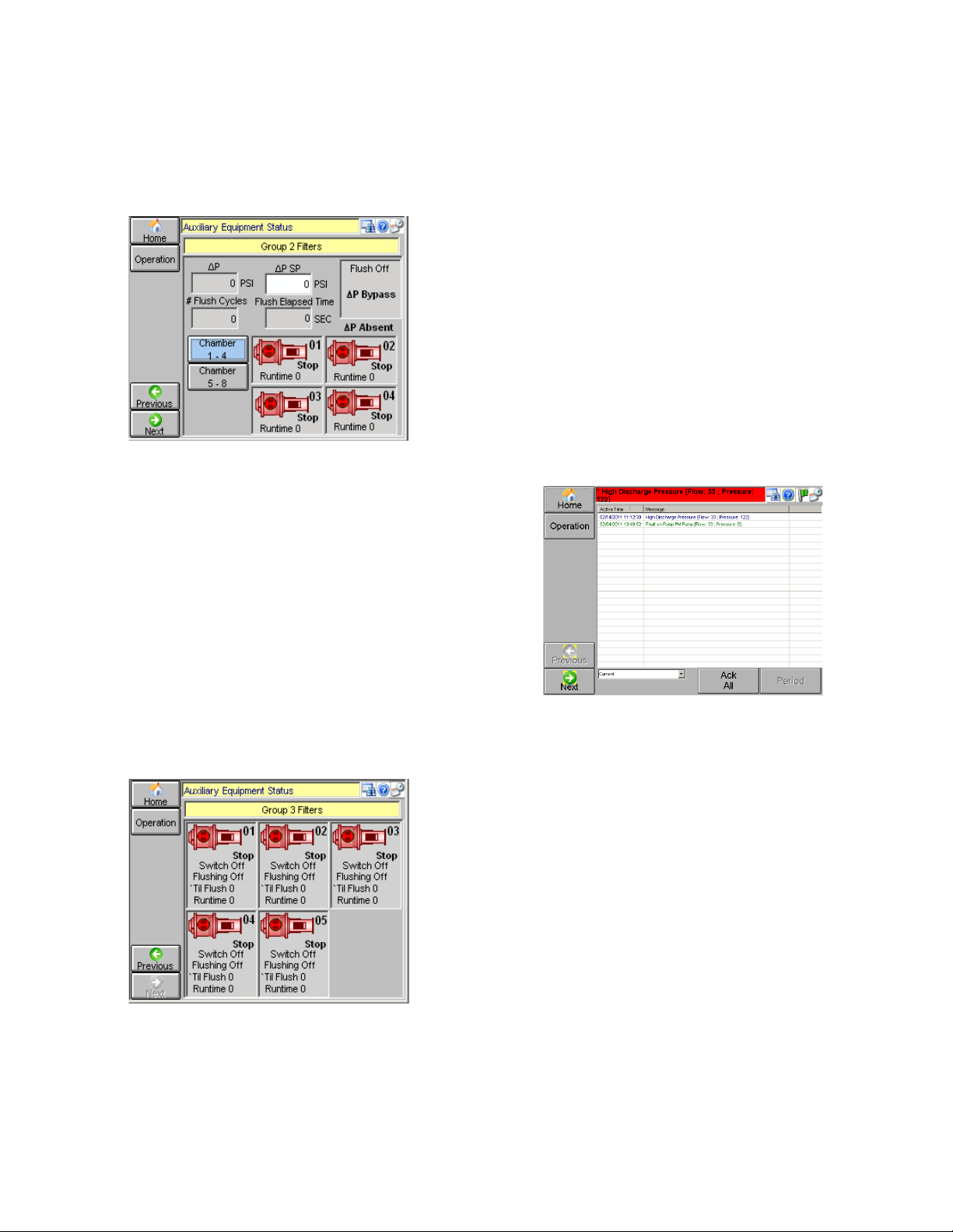
Scanner Filters Monitoring Screen
The scanner filter monitoring screen shows the
status of a single filter with up to eight chambers.
The inset box shows if the flush cycle is on or off, if
the enclosure filter switch is set to on or off, if ΔP is
bypassed, and if a filter faults, ‘Fault’ blinks as a
notification. Text showing that ΔP is present or
absent is displayed below the box.
Page 14
14
Red, no animation: Stopped
Green, rotating center: Running
Yellow, flashing center: Fault condition
Tap [Next] to move to the next status screen.
Figure 25: Scanner Filter Monitoring Screen
Solid Separators Monitoring Screen
This screen shows the status information for up to
five installed filters. The Solid Separators Status
icon also shows the filter number, the status,
whether the enclosure switch (Switch) is set to on
or off, if the Flushing switch is set to on or off, the
time until the next flush is shown in seconds (‘Til
Flush), and filter Runtime is displayed in hours
(Runtime).
Red, no animation: Stopped
Green, rotating center: Running
Yellow, flashing center: Fault condition
Tap [Next] to move to the next status screen.
Figure 26: Solid Filter Monitoring Screen
ALARMS
Tap [Alarms] from the Operations menu.
The alarms screen shows all current and
unacknowledged alarm events. Use the vertical
scroll bar to view all alarm events if necessary.
The latest alarm flashes in the banner at the top of
the screen till it is acknowledged using [Ack All].
NOTE: Be sure to scroll to the bottom of the alarm
events list before using [Ack All] to ensure that all
alarms have been viewed.
Alarm notifications are color coded.
Red: Active, Unacknowledged Alarm
Green: Active, Acknowledged Alarm
Blue: Inactive, Unacknowledged Alarm
To view alarm events from the past, from the drop
down menu at bottom left, select ‘History’. Tap
[Period], and enter the start and end dates in a pop
up screen. Tap [Apply] to save changes or [Close]
to cancel.
Figure 27: Alarms Screen
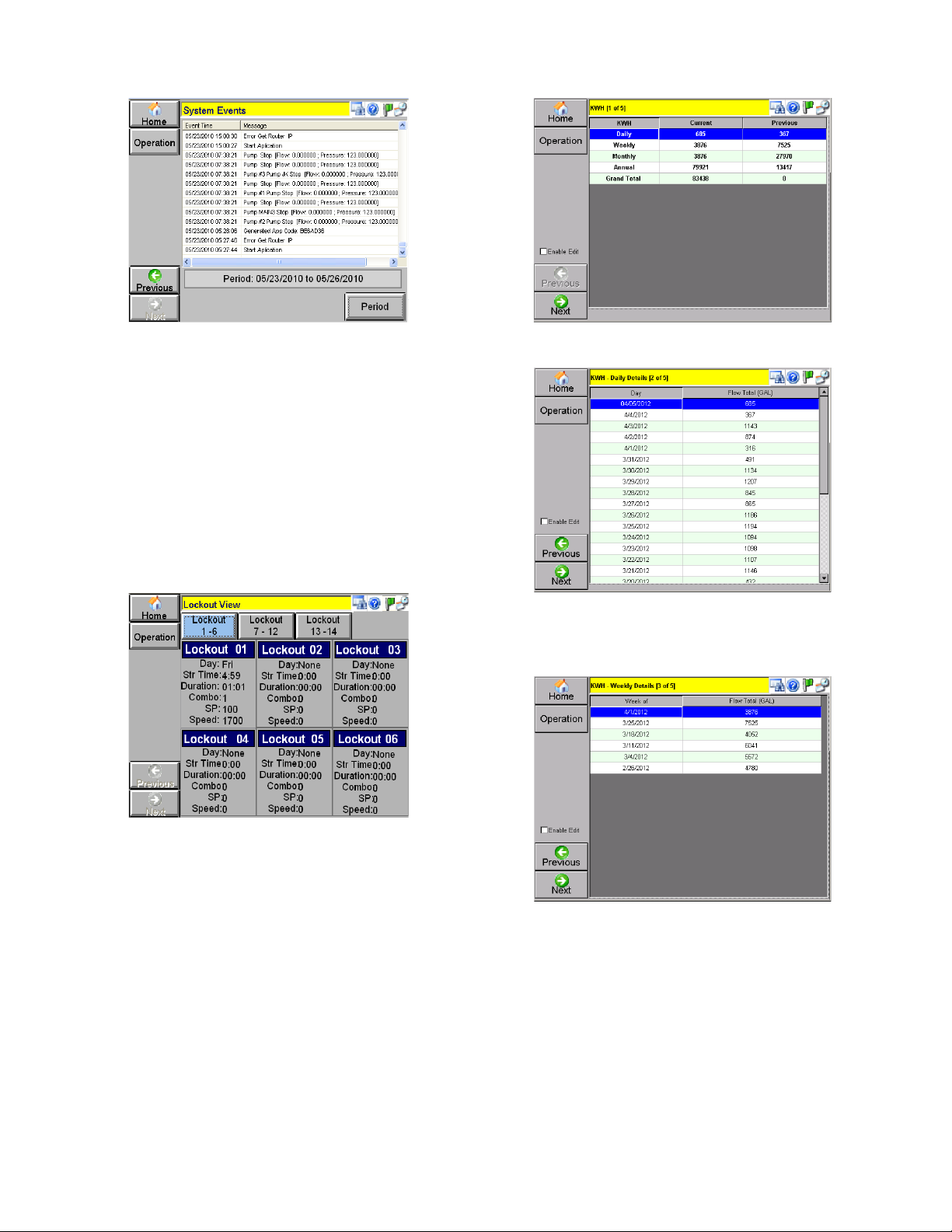
EVENTS
Tap [Events] from the Operation menu.
This screen shows system events for current day,
date & time, and a short message about the event.
To view past events, tap [Period] and specify the
start and end date to view the events.
More events may be viewed using the vertical scroll
bar.
Page 15
15
Figure 28: Events Screen
LOCKOUT VIEW
Tap [Lockout View] from the Operations menu.
Lockouts are common when water usage and
power restrictions limit pump usage to a certain
time.
Different lockouts may be viewed using the
numbered tabs at top. The Day selected, the Start
Time, the Duration, the Combo number selected,
the Combo SP (combo setpoint), and the pump
Speed are shown.
Figure 29: Lockout View Screen
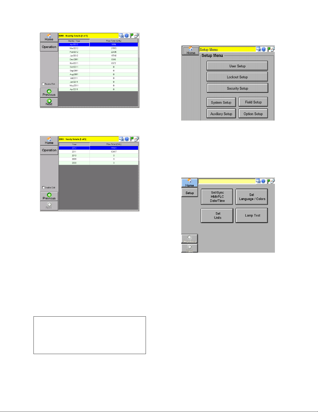
KWH RECORDS
Tap [KWH Records] from Operations menu.
The KWH Records are similar to the Totalizers and
record power usage.
NOTE: The data on this screen is available only
when used with Toro™ or Lynx™ irrigation control
systems and/or KW Measurement hardware is
installed.
Figure 30: KWH Records, Overview
Figure 31: KWH Records, Daily Usage
Figure 32: KWH Records, Weekly Usage
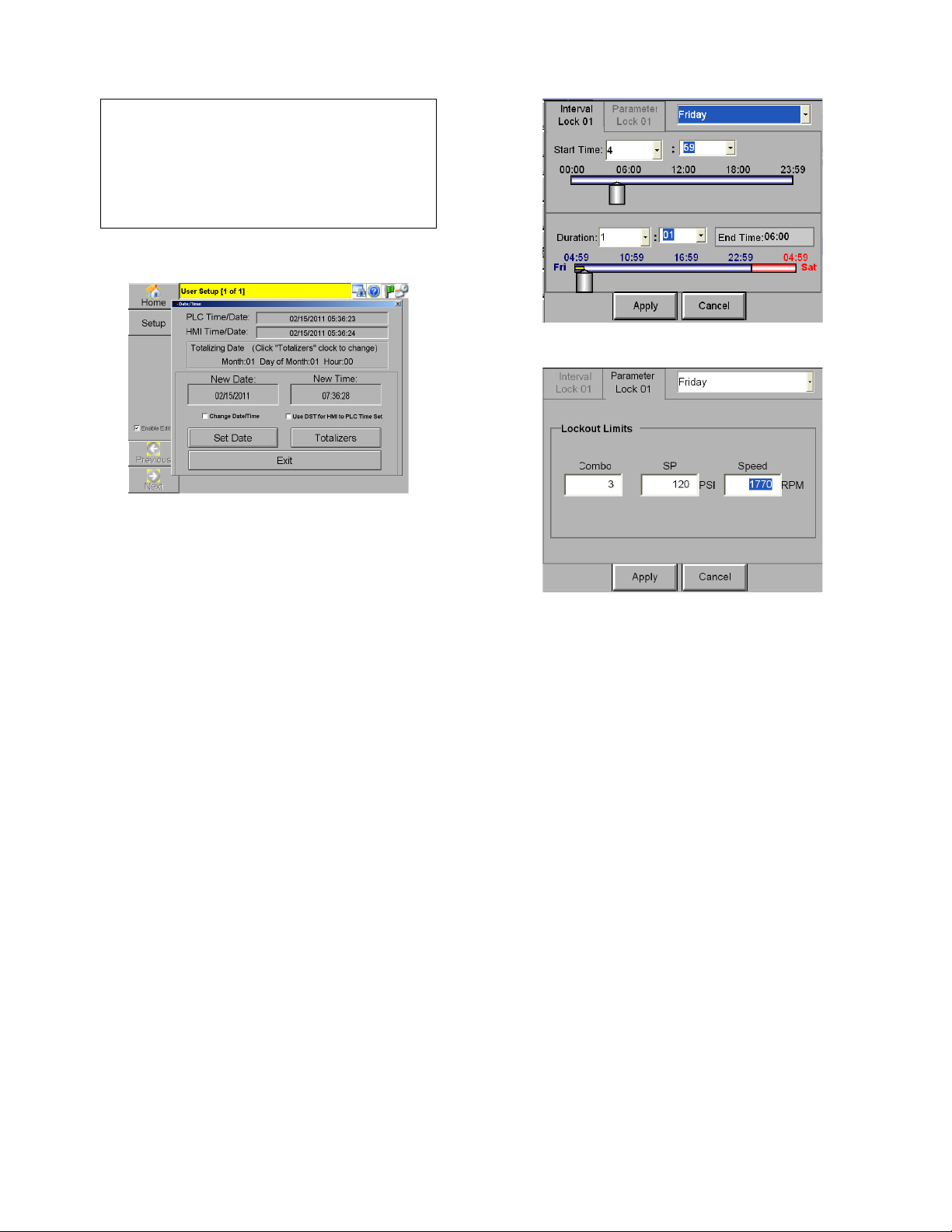
Page 16
16
Figure 33: KWH Records, Monthly Usage
Figure 34: KWH Records, Yearly Usage
Note: KHW Metering and records are subject to
calibration and will only monitor the loads
connected to the measurement equipment,
primarily irrigation pumps. The records are intended
as a reference to plan irrigation for maximum
efficiency and are not to be used as a custody
transfer or billing meter.
Setup Menu
Tap [Setup] from the Home screen.
The Setup menu is available for Supervisor use
only.
CAUTION:
Changing the settings in the Setup Menu will
affect the functionality of the system. It is
advisable to record any current settings before
making changes.
Figure 35: Setup Menu
USER SETUP
Tap [User Setup] from the setup menu.
This menu allows a supervisor to set the date/time,
language, colors, and units. A lamp test to check all
lamps on the control panel may also be performed.
Figure 36: User Setup Menu
NOTE: The [Set Language/Colors] and [Set Units]
menu selections are not currently available.
Set/Sync HMI-PLC Date/Time
Tap [Set/Sync HMI-PLC Date/Time] from the User
Setup menu.
This screen allows the date and time to be set, and
synchronized for the PLC and HMI. Tap
[Synchronize] to synchronize HMI & PLC date and
time.
In a new pop up screen, enter the date and time.
Tap [Set Date/Time – Close] to save changes. Tap
[Clear Totalizers] to clear all totalizers.
Note that when the HMI time is set, the HMI will
automatically sync the PLC time once/day.
Page 17
17
CAUTION:
Synchronization should not be done while
using the Internet-based remote client as this
has the potential to negatively affect the time
settings of the system. Syncing should only be
performed locally.
Figure 37: Set/Sync HMI-PLC Date/Time
Lamp Test
Tap [Lamp Test] from the User Setup menu.
Holding this button for 3 seconds causes all lights
on the control panel to light up briefly. Any bulb that
does not light up should be replaced.
LOCKOUT SETUP
Tap [Lockout Setup] from the Setup Menu.
Lockout setup is similar in appearance to the
Lockout View accessible in the Operation menu.
Individual lockouts may be setup by tapping over
each lockout inset. Tapping any inset opens a
configuration window. The day, start time, and
duration may be entered in the interval tab at the
top. In the parameter tab, the combo number,
setpoint, and speed can be entered. Tap [Apply] to
save settings or [Close] to discard any changes.
An individual lockout setup screen is shown below.
Figure 38: Individual Lockout Setup
Figure 39: Parameter Tab in Lockout Setup
The screen shown in Figure 38 sets up a lockout for
Friday beginning at 4:59 AM. The duration is set to
be 1 hour and 1 minute. Thus this lockout will end
at 6:00 AM on Friday. The animated display gives
an indication about time. The Parameter tab
enables a user to define Combo number, maximum
pressure, and maximum speed in RPM.
SECURITY SETUP
Tap [Security Setup] from the Setup Menu.
The Supervisor can change the password assigned
to him/her, and set the number of days after which
the password expires (in the editable field). To
change the password, tap [Change Password] to
change the supervisor password. Enter the new
password in the ‘Password’ and ‘Confirm Password’
field. Tap [Apply] to save changes.
NOTE: Tap [Generate App Code] if your current
Technician password has expired. Use this App
code when calling customer service to obtain a new
password. The [Generate App Code] button is
available to any user without a password.
Page 18

18
Figure 40: Security Setup
SYSTEM SETUP
Tap [System Setup] from the Setup Menu.
A statement will appear warning you that changing
system settings could affect the functionality of the
entire system. You must accept this to proceed.
You can navigate the status screens for each
device that has been set up by tapping [Previous]
or [Next].
NOTE: The screens described below will only be
displayed if they are applicable to the current
system.
Job Information
Enter the job information such as ‘Job Number’,
‘Job Name’, ‘Main PLC IP (usually 192.168.1.10),
and ‘Phone Number’. Notice that the fields ‘HMI
Version’ and ‘PLC Version’ have been grayed out,
and are not editable.
Tap [Next] to move to the next System Setup
screen.
Figure 41: Job Information
Basic Pump Information
The number of pumps can be selected from a drop
down menu. Each pump can be assigned a name in
the editable fields at the bottom of the screen.
Tap [Next] to move to the next System Setup
screen.
Figure 42: Basic Pump Information
Zone Configuration
The number of flow zones is adjusted here. Up to
7 zones can be selected. This controls how many
flow totalizers are operable. Each flow zone will
keep track of water usage by day, week, month
and year (5 years).
Figure 43: Zone Configuration
The name of the flow zone is set here. Also, the
flow channel that is totalized for each zone is
configured here. These channels match the flow
channels from calibration. In addition to picking a
single channel for a particular zone, multiple
channels can be added together to form a single
flow zone by selcting more than one “Zone” to
totalize. Well pump flows can also be selected for
flow zones and even added to irrigation channels as
required. Flow zones can also be subtracted from
the total by selecting a “Subtract Flows” channel.
This may be required when a meter reads flows
going to more than one zone, and one of these
subsequent zones is metered separately.
Flow filtering is setup here as well. By selecting
“Disable Flow Reading if No Pump Running” for a
channel, that flow reading will be zero’ out when no
pump is running. This is in case the system picks
Page 19

19
up fluctuations that cause the meter to generate
undesirable small flows when the pumps are not
running.
Pump Configuration
Each pump can be selected from a drop down
menu in this screen. Each pump can be assigned a
group, type, and number of VFDs that are going to
be used. Also selections can be made regarding the
pump being a XL, VFD, HPT, HSS, or Only pump
for this VFD.
Enter the minimum run time, Spindown Time, Pump
Capacity, Feedback Delay for each pump.
Tap [Next] to move to the next System Setup
screen.
Figure 44: Pump Configuration
After defining your contactor pump setup, a quick
start-stop on Test mode is recommended to verify
the settings are right. (Check XL or VFD contactors
and VFD relay per pump).
To run a Quick Start-Stop test, perform the
following:
Set all pump switches to OFF
Put the system switch into TEST mode.
For the pump being tested:
Turn ON the pump switch for 3-4 seconds to
verify proper setup.
The pump should run when switched to ON and
stop when switched to OFF.
The pump should not fault – which is indicated
by a flashing pump switch light.
Caution: Pressure surges
Care should be taken to isolate the irrigation
system from pressure surges during this test.
Tap [Next] to move to the next System Setup
screen.
Alarm Setup
This screen allows you to select various alarm
types from the drop down menu, and fill in the
required settings for each alarm.
Figure 45: Alarm Setup
Default settings (standard factory settings) can be
found in Appendix D.
Tap [Next] to move to the next System Setup
screen.
Combo Options
This screen allows you to checkmark various
combo options. ‘PSI Start Enable’ and ‘PSI stop
Enable’ are essential. Without these two, the station
will not start stop based on pressure indications. All
other check-marks are need based.
Figure 46: Combo Options
Logic flow enables you to select which zones are
used for flow shutoff. The zones are added
together to provide the flow to compare to the flow
shutoff setpoints.
This screen also contains the power monitor.
Page 20

20
This is the final System Setup Screen. Tap
[Previous] to move to the prior System Setup
screen or tap [Setup] to return to the menu.
FIELD SETUP
Tap [Field Setup] from the Setup menu.
Figure 47: PID Settings
After the pumping station is configured with initial
values at the factory, field technicians can use the
four Field Setup screens to tune or optimize the
station operation.
You can navigate the status screens for each
device that has been set up by tapping [Previous] or
[Next].
NOTE: The screens described below will only be
displayed if they are applicable to the current
system.
PID Tuning
All fields which have been grayed out are read only.
Figure 48: PID Settings
PID Group:
There are 5 PID sets available for use that are
chosen by which pump(s) are running on VFD.
Pumps using this PID Set:
The decision on which PID set to use is based on
the “best” fit of pumps running on VFD and the
pumps selected here.
Read:
Click “Read” to read the PID values from the PID
group set selected (this is automatically clicked for
you when you enter the screen).
Write:
Click “Write” to save the values to the PID group.
Copying PID data:
The Read/Write buttons are provided to allow the
technician to copy values from one PID group to the
other. To copy, select the PID group to copy from
and click “Read”, then select the PID group to copy
to and press “Write”.
Speed Test:
Speed test is a method to shut down the lead VFD.
When only 1 VFD is running. The PID value is
artificially reduced and the system is monitored for
PID response (pressure drop).
Speed Test shutdown is initiated when flow falls
below “Flow “ for “Delay” seconds.
“Speed” is the speed to which the PID must drop to
pass speed test and shut down the pump.
“Period” is the time between steps for the speed
test routine to lower the PID output, and “Step Size”
is the amout of PID drop per step.
If the speed test routine detects the PID ramping up
during the test, speed test will abort and operation
will return to normal until flow is again below the
“Flow” setpoint for “Delay” seconds.
Proportional and Derivative settings, high and
low flow:
Configuring the proportional and derivitave values is
essentially a trade-off. Both these values have an
impact on the system response. A high proportional
value causes the system to respond faster, thus
reaching the setpoint faster. At the same time, this
faster response means, that the system will easily
overshoot the desired setpoint. This can be
checked by lowering the proportional value, and
increasing the derivative (d-Term) value. The
integral value controls the sampling rate of the PID
loop. The derivative term controls the systems
Page 21

21
response to rapid changes in pressure, regardless
of the value of the pressure. This system uses this
to begin reducing VFD output speed when pressure
is rising quickly, helping to avoid overshoot. The
system can also detect fast pressure drops to begin
increasing VFD output speed before large errors
are detected, increasing the systems
responsiveness.
Good starting values are 25 for Kp and 12 for Kd.
Increase Kp when the system lags too long
changing the speed when pressure is away from
setpoint but relatively steady. Decrease Kp and
increase Kd to reduce overshoot. Decrease Kd
when the system becomes unsteady near setpoint
under steady demand. Generally speaking, only
use enough Kd to reduce overshoot.
Low and high flow settings:
The low flow and high flow settings are used
together to calculate the P and D terms at any given
time. The low flow settings are what the P and D
terms would be if flow were 0. The High Flow
settings are what the P and D terms would be if flow
were greater than or equal to “Max Flow for
Low/High Flow”. The value to use for each
parameter is calculated based on the flow at the
time.
Example: Low Flow Proportional is 10, and High
Flow Proportional is 20, “Max Flow for Low/High
Flow” is 2000. At 1000 gpm, the proportional value
will be calculated to be 15. At 1500 gpm, the
proportional value will be calculated to be 17.5.
Minimum Speed: This is the minimum speed that
the system will operate the VFD under PID control.
This speed should equal the minimum speed that
the pump will flow water at setpoint pressure.
Setting this value too high can cause
overpressurization at low demands, but having this
value too low can cause the PID to hunt since the
speeds below the “true” min speed are ineffective
and cause unnecessary delay in the PID when
operating in these speed ranges. Note that
allowances must be made for varying inlet pressure
and adjustable setpoints. Generally speaking, a low
Min speed is better than a too-high min speed, but
the closer to “true” min speed this is set, the better
the system will operate.
Control Deadband:
This value controls how far from setpoint the
pressure must be before the PID responds. The
units here are in 0.01 psi, so 25=0.25 psi (one
quarter-pound). This smooths the PID response
near setpoint and allows flow waves in the irrigation
to dissipate. However, to large a value here will
cause the system to delay response and could
cause the system to “get behind” in response to a
large change in demand.
Transition Control:
Starting Speed: Starting speed of the Main VFD
when the Main Pump first starts. Should be high
enough to “kick start” the pump since it is starting
under unsupplied demand, but care must be taken
not to force the system to overshoot under low
demand situations. Start the system with demand
just greater than the PM Pumps (or Jockey Pump,
as supplied) capacity and adjust for minimal
overshoot.
Combo Up (After XL Start): This setting controls
the speed the VFD running the main pump will be
forced to when a fixed speed lag pump starts. This
helps prevent overpressuring by reducing the
capacity of the VFD Pump, which is then being
provided by the fixed speed pump after it starts.
Generally set to 1/3 the value between min speed
and 32767. This speed will be held for “Hold Sec”,
which is generally set to 1 (may need to increase
for systems using soft-starters for fixed speed lag
pumps).
Combo Down (After XL Stop): This setting
controls the speed the VFD running the main pump
will be forced to when a fixed speed lag pump
stops. This helps replace the capacity provided by
the fixed speed pump and eliminate pressure dips
when these pumps are shut off. Generally set to
2/3 the value between min speed and 32767. This
speed will be held for “Hold Sec”, which is generally
set to 1.
Speed at 0 psi Startup: This setting controls the
speed the VFD of the Jockey OR main will start if
pressure is very low when the pump starts (see
deadband below). This setting should be adjusted
to be the point the pump just begins to flow water at
0 psi discharge. The actual starting speed will be
calculated between this speed and “Combo Down
(After XL Stop)” speed setting, depending on the
actual pressure at the time of start. A function is
used to calculate the speed between these points.
Threshold Deadband (psi): Determines the
pressure below setpoint to use the Threshold
function for determining starting speed. If set to
“20”, the threshold function is used to calculate
starting speed when pressure is equal to or less
than 20 psi below setpoint.
The VFD 1
st
start factor corresponds to the starting
speed of the first main or Jockey pump starting on
VFD. A high value causes the VFD to start running
at a higher speed, creating more pressure. This
Page 22

22
helps the system to reach the setpoint faster, but at
the same time the system may overshoot the
setpoint very quickly since the PID does not have
enough time to react to the fast occurring changes.
A very low value will make the system take a lot of
time to reach the setpoint.
The values shown in figure 34 below have been
determined from empirical tests, and can be used
as defaults, but each system needs to be tuned, as
pumps and systems are different.
Low Flow (Proportional & Integral) denotes the PID
sensitivity on the first start of the first main.
Tap [Next] to move to the next Field Setup screen.
Figure 49: OPA, Ramp Up and Dp/Dt control
OPA Enable
This is a method used to shut down lag pumps
operating across-the-line in a system that uses both
VFD and XL (across-the-line) pumps. Check this
box to enable.
The overpressure accumulator measures the
overpressure, and calculates a value to addd to the
Overpressure Accumulator depending on this error
on each program scan. The system will shut off a
lag pump when “Trip Preset” is reached.
Min combo: Combo # on which, OPA is not desired
because it is desired that the last pump stop in
speed test.
Ramp Up:
Step (psi): During ramp-up, the # of psi the system
will step up. See “Step (sec)”. Normally set to 1 psi.
Step (sec): During Ramp Up, the time between
ramping the setpoint. Normally set to 4 sec.
dP/dT Control:
Enable (Checkbox): Controls whether the “dP/dT”
pump start/stop control functionality is utilized.
Check to utilize the rate of pressure drop when
starting/stopping pumps.
Start/Stop Inhibit : The rate at which the system
will inhibit pump starts or stops as the pressure rise
or drops during the decision process. Generally
0.5-1.0 is adequate to reduce pump cycling.
PM Skip: Controls how much pressure drop will
cause the system to automatically skip the PM
Pump in the sequence. Fast pressure drop
indicates a large demand has suddenly been
applied to the irrigation system. This is used to
detect the need to skip the small pressure
maintenance pump so that the main pump can
meet this demand as quickly as possible, avoiding
unnecessary pressure dips. Start with values at 1.0
and monitor. To disable this feature but continue to
use the Start/Stop inhibit system above, set this
value to 10 or greater.
dP/dT Inhibit(sec): After the main pump stops,
systems will often experience short pressure dips
that may cause the PM Skip system to restart the
main pump. Set this value to 20 seconds to prevent
the PM Skip process from restarting the main pump
within this period of time.
Current dP/dT values are shown to assist in
tuning the dP/dT system.
Combos
This screen allows you to configure various options
in a combo.
Select the maximum number of combos (up to
eight). For Combo 0, which is the ‘no pump’ combo,
all values except Overlap gray out. A brief
description of all parameters follows.
1. Delay Timer:
Start: number of seconds the station delays before
the start of the specified combo, once ∆P has been
reached
Stop: number of seconds the station delays before
it stops the specified combo, once ∆P has been
exceeded.
2. Normal Differential:
System is not in ‘Bypass’ mode.
Start: Start a specified combo when the difference
between the actual pressure and user defined SP
exceeds this value.
Stop: Stop a specified combo when the difference
between the actual pressure and user defined SP
exceeds this value.
3. Bypass Differential:
System is in VFD Bypass mode. Enabling bypass
for a particular VFD causes all pumps using that
Page 23

23
VFD to go into “Bypass Mode” which means they
will operate as fixed-speed pumps.
Start: Start a specified combo when the difference
between the actual pressure and user defined SP
exceeds this value.
Stop: Stop a specified combo when the difference
between the actual pressure and user defined SP
exceeds this value.
Tap [Next] to move to the next Field Setup screen.
Figure 50: Combos
Combo Pumps
This screen allows you to configure which pump will
be used in which combo.
Tap [Next] to move to the next Field Setup screen.
Figure 51: Combo Pumps
AUXILIARY SETUP
Tap [Auxiliary Setup] from the Setup menu.
These screens allow you to setup and configure
any auxiliary equipment. Check any auxiliary
equipment that needs to be set up.
Each enabled item requires an IP address to
communicate to the PLC using the Modbus
protocol, which can be entered by double clicking
on the IP address field.
Default IP addresses can be found in Appendix E.
Note: Pace 5.0+ supports integrated auximilary
equipment. Setting the IP address of the auxiliary
equipment to the same as the main PLC enables
the integrated auxiliary device.
Page 24

24
You can navigate the status screens for each
device that has been set up by tapping [Previous] or
[Next].
NOTE: The screens described below will only be
displayed if they are applicable to the current
system.
Figure 52: Auxiliary Equipment Setup
Note: Timed Pump operation is included in Lake
Level control operation if using and integrated
controller (included in main PLC).
Booster Setup
The terms in this menu are described below:
Stop Pressure: If pressure rises above this value,
system stops.
Low Inlet Pressure: If inlet pressure falls below
this value, a Low Inlet fault is activated.
Low Dschrg Pressure: If pressure falls below this
value, a Low Discharge fault is activated.
High Dschrg Pressure: If pressure rises above this
value, a High Discharge fault is activated.
Pressure SP: User defined pressure maintained for
the booster.
Tap [Pump Config] to enter configurations for each
of the booster pumps in a popover screen. Up to 3
pumps may be configured.
Tap [Time Delay] to enter time delays in a popover
screen.
Tap [Next] to move to the next Auxiliary Setup
screen.
Figure 53: Booster Setup
ALS Setup
In this screen, Flush Times and Flow Rates may be
edited.
Time until Flush (sec): Time period between
flushes.
Duration of Flush (sec): Time duration for the
flush.
Flow Start Cleaning (GPM): Flow rate when flush
starts.
Flow Stop Cleaning (GPM): Flow rate when flush
stops.
Tap [Next] to move to the next Auxiliary Setup
screen
Figure 54: ALS Setup
Lake Level Controls Setup
This screen allows you to configure all aspects of
Lake fill, transfer pump and timed pump operation
when using an integrated lake level control system.
Page 25

25
Figure 55: Lake Level Controls Setup
Up to 8 Well/Transfer/Timed pumps can be
controlled when using the integrated system. Set
the IP address of the lake Level Controls auxiliary
equipment to match the main PLC to enable the
integrated controls (Note: The IO mapping must be
configured for the Lakefill/Transfer/Timed pumps to
use the integrated system, consult the factory when
adding equipment to 5.0+ Pace systems).
The master Auto button must be enabled for any of
the level/timed pumps to run. Press “System Off” to
disable all Level/Timed pumps. (Pump station
operation is not affected).
Touch the pump name to configure the pump.
Figure 56: Level/Timed pump configuration
Set the pump name by touching the Name field for
the pump you are configuring. This is the “Source”.
Each pump can be configured to run individually or
as part of a pump group. For each pump to run
standalone based on it’s own level control, select
each pump to be in a separate group. To use the
run-time of the pumps to “Lead Select” a group of
well pumps, put them in the same group. When the
first pumps level (or level/time combination) calls for
the pump to run, all pumps in the group will be
evaluated to determine which will run, based on run
hours and switch settings.
Timed pump can be configured with or without level
control. A timed pump will be enabled to run on the
days specified, after the start time and for the
duration specified. If also level controlled, then the
pump will be allowed to run during the “enabled”
period when the level in the controlled lake calls for
the pump to run. If no level control is also
configured, the pump will run after the start time
and for the duration specified. Setting up the timed
operation will be described in detail below.
Start and Stop delays apply to level control and are
used to de-bounce, or account for wave action on
the probes or transducer signal.
Selecting a transducer tells the system to use the
transducer signal for level control rather than level
probes/floats.
Well/Txfr allows you to set up the pump as Well or
Transfer (Well pumps “Pump up” while Transfer
pumps “Pump Down”, though this distinction only
truly matters when using the transducer for level
control, both modes require a signal-on to run when
using probes for control).
Fbk selects whether the pump will provide a
feedback (pump running confirmation) to the PLC.
If selected, a pump fault will be reported if the pump
does not provide this feedback signal when called
to run. If not selected, the PLC will assume the
pump is running any time it is called for.
Fault Enables select whether to enable faults for the
well/transfer/timed pumps. LL enables Low Level
Safety, HPT enables the High Pump Temp safety,
and Seal enables the Seal Failure safety. HPT and
Seal are typically for submersible sump-type
pumps while Low Level safety is typically used for
turbine or submersible turbine type pumps.
Configuring Timed Pumps:
Touch the pump image of any pump configured for
timed operation to open the Run Time configuration
screen.
Timed pump control consists of a Day to Enable,
Start time and Duration. The start day, time and
duration are taken together to determine if the
pump is in an allowable period to run. If the current
time is greater than the time period defined by Start
time and day, and less than start time and day, plus
duration, then the pump will be allowed to run.
Note that this means it is possible for a pump to run
Page 26

26
on a day that is not selected if the previous days
duration setting extends past midnight.
Figure 57: Integrated Timed Pump configuration
For example, assume the pump is configured as
shown above. If the current time is Monday-Friday,
between 2:00 AM and 6:30 AM, the city fill valve will
be open if the probes for #8 Pond call for it. Any
other time the controls will ignore the probes and
the valve will remain closed.
If the setting were configured for 10:00 PM and the
duration was set for 4:00 hors, the pump could run
starting at 10:00 PM Monday-Friday, and would be
allowed to run until 2:00 AM the following morning
(even Saturday morning) but would not start
Saturday or Sunday evening (and would thus not
run Monday morning from midnight to 2:00 AM).
Lake Level Controls Setup (Non-Integrated only)
This screen allows you to enter the delay times for
the pump to start and stop after a specified level
has been reached. Time to Fault (sec) is the time
delay for system to issue a fault after a fault occurs.
Tap [Lvl Setup] to enter the start and stop levels
(feet) for up to 5 pumps in a popover screen.
Specify the type of pump using the radio buttons.
A well pump starts when the well water level falls
below the start level, and stops when the water
level is above the start level.
A transfer pump starts when the water level in the
tank is above the start level, and stops when the
level falls below the stop level.
Tap [Next] to move to the next Auxiliary Setup
screen.
Figure 58: Lake Level Controls Setup
Timed Pump Setup (Non-Integrated only)
This screen allows you to enable the timed pump
setup. If the ‘Feedback Enable’ box is checked, the
pump will send feedback to the PLC.
Enable the checkboxes for each day that a pump
needs to be timed. For each day enabled, enter the
start time and duration in a pop up screen.
Tap [Next] to move to the next Auxiliary Setup
screen.
Figure 59: Timed Pump Setup
Simple Filters Setup
This screen allows you to setup the simple or Wye
filters.
∆P Present (sec) is the time between flushes when
differential pressure is on, or when the analog
differential pressure is less than the differential
setpoint. Check the ‘Wye’ checkbox to enable a
Wye filter, (which doesn’t use ∆P) and enter values
in editable fields.
Simple Filters Setup
This screen allows you to setup the simple or Wye
filters.
Page 27

27
∆P Present (sec) is the time between flushes when
differential pressure is on, or when the analog
differential pressure is less than the differential
setpoint. Check the ‘Wye’ checkbox to enable a
Wye filter, (which doesn’t use ∆P) and enter values
in editable fields.
Tap [Next] to move to the next Auxiliary Setup
screen.
Figure 60: Simple Filters Setup
Scanners Filter Setup
The Scanners Filter setup screen is similar to
Simple Filters setup, but it does not have the Wye
filter option.
Select the filter from the drop down menu and enter
values in the editable fields as needed.
Tap [Next] to move to the next Auxiliary Setup
screen.
Figure 61: Scanners Filter Setup
Options Setup
Tap [Options Setup] from the Setup Menu.
NOTE: After the pumping station is configured with
initial values at the factory, this menu allows you to
configure additional options.
Tap over any field to access the desired setup
options.
Figure 62: Options Setup Menu
VFD Bypass
Tap [VFD Bypass] from the Options Setup Menu.
This screen allows you to enable or disable bypass
for desired VFDs using the radio buttons.
Tap [Close] to return to the Options Setup Menu.
Figure 63: VFD Bypass
Analog Scaling
Tap [Analog Scaling] from the Options Setup Menu.
This screen allows you to scale raw values into
engineering units for up to 4 analog signal inputs
and outputs.
For each signal such as Pressure, the analog input
values are shown on the left while the analog output
values are shown on the right.
Use the scroll bar to scroll left and right. Enter
values in all editable fields.
Tap [Edit Analog I/O Names] to change any of the
names of the variables displayed (Flow, Pressure,
etc). This can also be used when adding on
functionality to the system. There are a few ‘spare’
Page 28

28
I/O names available and those can be edited to
match the new variable for scaling.
Tap [Close] to return to the Options Setup Menu.
Figure 64: Analog Scaling
ActiveX and IP Updates
Tap [ActiveX and IP Updates] from the Options
Setup Menu.
By default both ISSymbol URL and Agent URL are
automatically populated.
View Current Configuration: View the entire URL
in a popover screen.
Set Configuration: Set and save new web
configurations.
Email: Get notifications via email.
Tap [Close] to return to the Options Setup Menu.
Figure 65: ActiveX and IP Updates
WinCE Remote Access
Tap [WinCE Remote Access] from the Options
Setup Menu.
This screen allows you to communicate with a
remote server using Telnet. This feature is intended
for advanced custom jobs.
CAUTION:
Before using this feature or changing any
settings on this screen, please call customer
service.
Tap [Close] to return to the Options Setup Menu.
Figure 66: WinCE Remote Access
Alternate SP
Tap [Alternate SP] from the Options Setup Menu.
Enter and store different alternate setpoints in the
pop up screen for Pressure SP and also alternate
setpoints for Fertigation SP.
Tap [Close] to return to the Options Setup Menu.
Figure 67: Alternate SP
Page 29

29
Figure 68: Pressure SP
Figure 69: Fertigation SP
Database Settings
This feature helps make changes to database
settings. The database is used to send and receive
information from the irrigation control system. The
“Gateway” software should be installed on the
irrigation computer and network connections
confirmed before enabling the remote database
connection.
The defaults will include:
Data Server: 192.168.1.15
Database:
For Windows “7” connected systems:
C:\Program Files (x86)\Flowtronex\FlxStationDataII.MDB
For Windows XP and earlier systems:
C:\Program Files\Flowtronex\FlxStationDataII.MDB
Enable Remote: Checked.
Note:
The database should only be enabled after
installing the “Gateway” software on the
irrigation PC. While the system will operate
correctly, unnecessary events and exceptions
are generated which can load the HMI
processor and take up valuable event-table
space.
Figure 70: Database Settings
After enabling the database connection, the HMI
must be restarted with the Gateway software
running on the host irrigation computer. This can be
accomplished through cycling power or by shutting
down and restarting the application.
Email Settings
This page allows you to set up email addresses
where Alarm and shutdown messages will be sent.
These emails will notify the user if the station has
shut down or experienced a problem that the site
personnel should be aware of. This way the user
will be notified immediately in case of a pump
station problem. If a fault occurs, an email will be
sent to him.
The email settings can be configured to send
emails to multiple individuals or email addresses.
The vast majority of cell phone providers also allow
email messages to be sent to cell phones as text
messages. A list of known formats is provided
below.
Enable: Check this box to enable email alarms
from the Pace controls.
Use Authentication: Check this box if your email
service requires POP3 authentication.
Note: The IP address of the POP3 server must be
the same as the IP address of the SMTP server.
This is usually the case (both servers usually reside
behind the same firewall/router).
To: Enter the email address to send the alarm
messages to. Multiple email addresses can be
Page 30

30
entered by separating the email addresses with a
semicolon.
Examples: Me@gmail.com; TheBoss@test.com;
SecondGuy@test.com; 555555555@verizon.net.
The following list shows email address formats for
various cell carriers. Sending an email to these
addresses will generate an SMS text message to
the cellular phone.
T-Mobile: phonenumber@tmomail.net
Virgin Mobile: phonenumber@vmobl.com
Cingular: phonenumber@cingularme.com
Sprint: phonenumber@messaging.sprintpcs.com
Verizon: phonenumber@vtext.com
Nextel: phonenumber@messaging.nextel.com
US Cellular: phonenumber@email.uscc.net
SunCom: phonenumber@tms.suncom.com
Powertel: phonenumber@ptel.net
AT&T: phonenumber@txt.att.net
Alltel: phonenumber@message.alltel.com
Metro PCS: phonenumber@MyMetroPcs.com
Where “phonenumber” is the 10 digit phone number
of the user.
SMTP: Enter the IP address of the SMTP server
you will be using. Windows CE devices require the
IP address rather than the server name.
See “Determining the IP address of the SMTP
server” in Appendix F for these instructions.
From: Enter the complete email address used for
this service. Most email servers will ignore your
email request if the “From” address does not match
the account.
Example: mypumpstation@runbox.com
User: For most email service providers, enter the
first part of the email address without the domain
name. Note that some providers require the full
email address as your user name.
Example: mypumpstation
Password: The password to your email account.
Example: flowtronex
After configuring your email settings, test the setup.
Tap [Set] to load the information into the email
generator. Then tap [Send]. A test email will be
immediately sent to the address(es) provided.
If the colored box remains green after hitting Send, the
configurations are working correctly. If the box turns
red there has been an error. The number after “Status”
indicates the type of error, table for which can be
found in Appendix F. Additional troubleshooting
options for email configuration can also be found in
Appendix F.
Figure 71: Email Settings
Occaisionally, the settings changes here may
require restarting the HMI. Try this if you
experience problems getting the test email to work.
This can be accomplished through cycling power or
by shutting down and restarting the application.
Then see appendix “F” for other troubleshooting
aids.
Setup/Configuration File
Tap [Setup File] from the Home screen.
Type the file name or browse for it using […].
The Configuration File screen lets you download an
XML file to the PLC, save an XML file from the PLC,
or delete an XML existing file on the PLC. The XML
configuration files contain the setup settings for
your pumping station.
CAUTION:
Downloading an incorrect XML file to the PLC
may render the system inoperable. Ensure
you have the correct file before selecting
[Download to PLC].
Page 31

31
Figure 72: Setup / Configuration File
Exit Application
Tap [Exit] from the Home Screen.
Exit will close the HMI interface and exit the
application. When [Exit] is tapped, the CEView
desktop is then displayed that gives the user the
ability to change operating system files. A warning
appears asking you to confirm your decision.
CAUTION:
No changes should be made to the operating
system unless directed by a Flowtronex
Customer Service technician. Functionality of
the HMI and the pumping station may be
affected by changes.
Figure 73: Exit App Warning
Networking and Remote Access
The general instructions and screen-shots provided
in this manual for operating the HMI may be used
when accessing the interface via the internet on a
personal computer.
For instructions related to configuring your personal
computer, please see appendix G.
Please note that when using a personal computer,
the touch-screen functionality is not available. To
navigate the screens:
• Click on the buttons with your mouse.
• Use your mouse to click in a blank
field. Enter text or numbers using a
standard PC keyboard.
Remote Software Log In
An identical version of the HMI software may be
accessed remotely by an Internet IP (Internet
Protocol) address. Type the following address into
an internet browser:
From within your network (at the maintenance
facility), open your web browser and type the
following URL into the address line:
http://192.168.1.15. This will take you directly to the
HMI’s web server.
To access your pump station from outside of your
network, you must first determine the IP address of
the router as seen from the internet. Note that this
can be somewhat difficult to determine without help
from your IT department (if you have one). The
router IP address can be found through the use of
3
rd
party IP address resolution sites (available on
the internet) or by navigating the router’s
administration pages.
In the pop up screen, enter your username and
password to log in.
After the HMI interface opens, the user type (from
Guest to Supervisor) may be changed by the
standard procedure described for touch panel
log in.
Web Reports
Internet users of the HMI interface can also view
and print different reports. There is an Alarms
Report, Historical Report, Usage Report, and
Factory Reports. The navigation bar allows the user
to access each report’s setup screen and print the
report. The trends screen can also be customized,
a feature which is unavailable in the local HMI
interface.
Log on to Web Reports
Log on to the reports menu by typing the following
in the address bar of your browser:
http://000.000.000.00/reportmenu.html
where 000.000.000.00 is replaced by your IP
address. Enter you username and password in the
log in screen displayed. Click [OK] to submit or
[Cancel] to cancel.
You can obtain your IP address through your IT
department or internet service provider.
Page 32
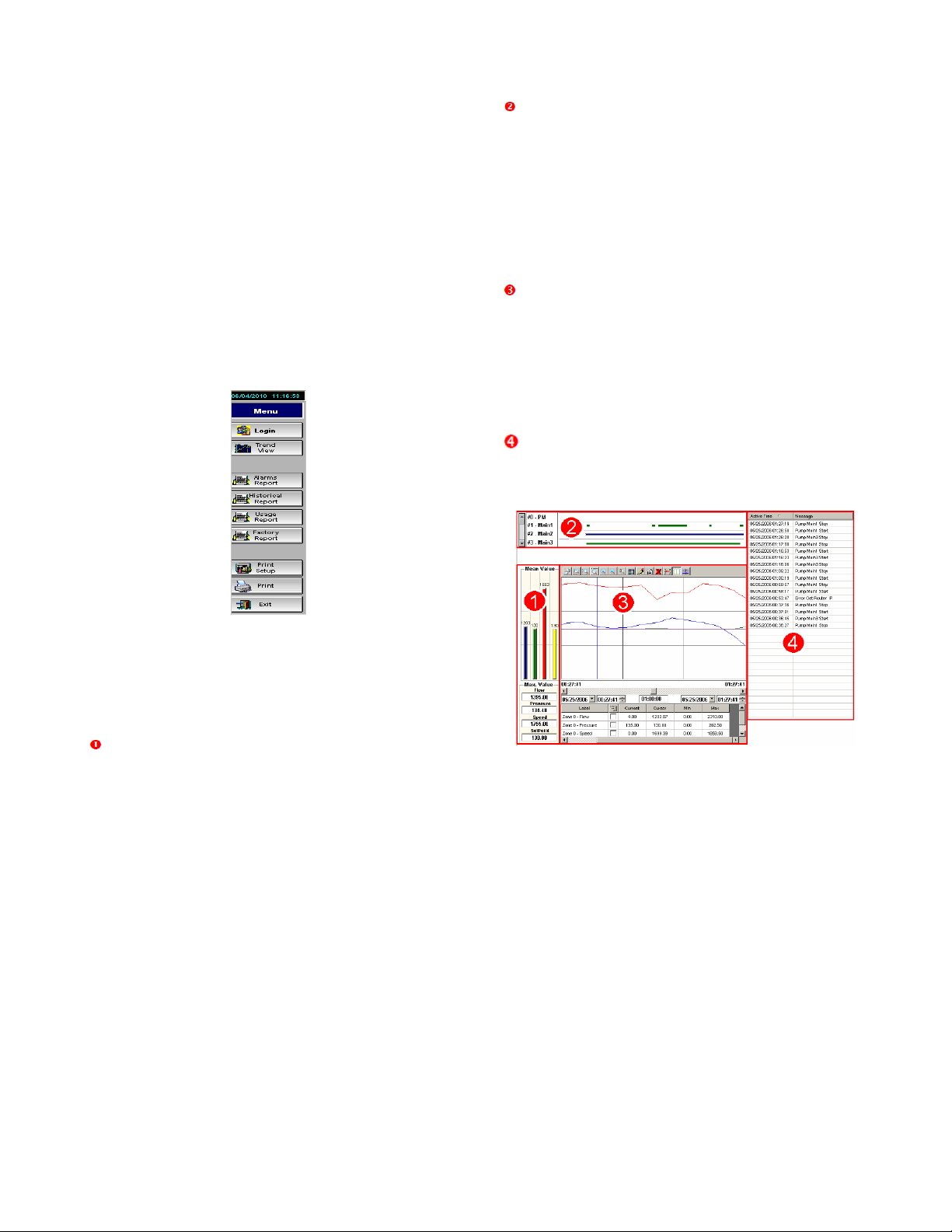
32
Web Reports Menu
After logging in, web reports menu is displayed
containing the following buttons, Login, Trend View,
Alarms Report, Historical Report, Usage Report,
Factory Report, Print Setup, Print, and Exit.
NOTE: Factory Report is available only to a
supervisor or technician. It includes a list of values
of various PLC registers and is not covered further
in this guide.
The banner at the top shows the current date and
time. Using this bar, alarm reports, usage reports
(in gallons), and several setup files in .xml format.
All reports can be printed. Use [Exit] to exit the
reports menu.
Figure 74: Web Reports Menu
Trend View
Select [Trend View] from the Web Reports Menu.
There are four key parts to the trends screen.
Mean Value Graph and Detail: For each of the
key variables (Flow, Pressure, Speed, and
Setpoint) the mean values are displayed as a
vertical bar graph on the top while the Maximum
values are displayed in fields below.
Pump Run Log: Graphically displays the pump
operation for the time frame selected. These are
color coded:
• Green - indicates pump is running
• Blue - indicates pump is running on
VFD.
• Red - indicates pump is in a fault
condition.
Variables Graph: Line graph displays colorcoded information for key variables over a specified
time. The top bar of the graph also has zoom,
period, and legend options. The grid below displays
variable data. Click […] to choose line colors.
Choose the start date, time and duration for the
graph from fields positioned between the graph and
grid.
Events Listing: Details the time and events for
a duration time defined by the user, as for the
variables graph.
Figure 75: Trends View
Alarms Report
Select [Alarms Report] from the Web Reports
Menu.
Alarms Report allows you to view the last 10
system alarms and events.
Page 33

33
Figure 76: Alarms & Events
All reports can be printed using [Print], after a
printer has been set up by clicking on [Print Setup].
Historical Report
Select [Historical Report] from the Web Reports
menu.
Historical Report allows you to access the data and
bar graph representation of your station’s Annual,
Monthly, and Weekly Flow information. The actual
gallons are shown in the data table on the left, and
three bar graphs (annual, monthly, and weekly) on
the right.
All reports can be printed using [Print], after a
printer has been set up by clicking on [Print Setup].
Figure 77: Historical Report
Usage Report
Select [Usage Report] from the Web Reports Menu.
Usage Report allows you to view the totalized flow
values for each day, week, month, and year. The
table in the middle on the left shows the times or
counters when totalizers reset. Table on bottom left
shows the number of starts, and runtime hours for
each pump.
Figure 78: Usage Report
Smart Phone and PDA access:
A simpler web page is available for smart phone
access. The IP address of this page is the external
address determined in appendix “G”, but a specific
page address is required to access the simplified
page: “<myIPAddress>/sma/logon.asp” where
<myIPAddress> is the external IP address. Note
that “192.168.1.15” will never be the correct
address since the smartphone or PDA is always
attempting to access the page from outside your
network.
Page 34

Appendix A–Glossary of Terms
The terms used in this manual are defined in the Glossary of Terms. In addition, other industry
specific or product-specific terms are included that may be used by technicians or customer
service when talking about your pumping system.
Across-the-line (XL)
Applying 100% of line voltage to a motor during startup and run. A simple
large relay with a contact for each power phase (for 3 phase) is used to
control the motor OFF/ON.
Analog
A signal that varies in some respect (voltage, current, frequency) in order to
convey the value of some real world information (i.e. pressure, flow,
temperature etc). A control system can take action based on the value of
such a signal. Internally, the signal will be converted to some number based
on the value of the signal.
Automatic lake screen
(ALS) A screen on the intake flume of the pump station, between the
irrigation pond and the wet well, which is designed to be self cleaning by
using a jet of clean water spraying from the inside-out during use.
Booster
A pump designed to increase the pressure of a pressurized irrigation line.
This is usually used to move pressurized water from a lower to higher
elevation area of the golf course.
Calibration
The act of or specific values used to scale the output of a measurement
device to read real-world values.
Chemical injection
The process of adding chemicals to irrigation water to fertilize or medicate
turf grass.
Combo
A capacity level representing a predefined group of pumps on a station.
Normally Combos are defined as follows:
Combo 1
Normally the PM pump.
Combo 2
Lead pump. Normally the VSP.
Combo 3
Lead pump and first lag pump.
Combo 4
Lead pump and two lag pumps.
Control valve
A valve designed to automatically open/close in order to maintain a specific
setpoint pressure, flow, or level.
Control variable
A value that a control system monitors in order to perform some useful
function.
Cycling
This condition occurs when conditions require a pump to start if no pump is
running, but require a pump to stop if a pump is running. This is excessive
starting and stopping of one or more pumps and can be damaging to the
equipment if allowed to continue.
Equal HP pumps
Also referred to as interchangeable pumps. Defines which pumps are
available to start based on lowest run time. VSPs and XL pumps are defined
in the PLC program. An XL pump can be an equal HP pump, but it will not
start as a lead pump, because the lead pump will always be a VSP.
Page 35

35
Filter
A device used downstream of the pumps to clean the water being pumped
into the irrigation. These devices are typically self-cleaning, but require
hardware/software to self-clean.
Fixed speed
Pumps run at a fixed RPM, defined by the motor windings and the frequency
of the line voltage (50/60 Hz).
Frequency
(Hz) The number of oscillations per second of any system. Typically used to
refer to electrical systems, such as AC power line frequency, or variable
speed drive output frequency. This frequency defines the speed of an AC
motor.
GPM
Gallons per minute. Units of flow for US use.
HSS
High speed switching. Starting pumps with a VFD to reduce inrush current
and provide pressure control, but able to switch over to fixed speed so that
the VFD is able to start another pump.
Input
A way for a control system to detect real-world occurrences. These can be
digital or analog.
Inverter
Another term for Variable Frequency Drive (VFD). Actually, more correctly
applied to the output circuitry of the drive, which converts DC voltage to AC
voltage.
Lag pump
A pump used later in the pump sequence to support increasing irrigation
demand requirements. The term lag simply refers to the fact that it does not
start first.
Lake fill
(LLC) A circuit designed to keep a pond or lake at or above some minimum
level of water.
Lead pump
The pump in a lead group which is chosen by the controller to start first. This
is usually determined by finding the pump in the lead group with the lowest
run-time.
Lockout
A system which limits the pump systems available pumps and or limits the
speed of a variable speed pump during user-defined time of day or day of
week.
Low level probe
A device that “shorts” out when removed from water. This removes the signal
from the PLC and tells it that the pump is not safe to run due to a low water
level condition.
Main pumps
The pumps which are relied on for supplying the irrigation at mid-high flow
rates.
Must-run time
The amount of time (in seconds) that the pump must run.
Output
A way for a control system to generate real world actions. An output can be a
120VAC signal to turn on a pump, or a varying 4-20 mA signal to control the
speed of a VFD. Many types of output are available.
Overload
A condition in which pumps are allowed to produce more flow rate than the
motor that drives them is designed for. Also refers to a device in the control
panel, which detects this situation and stops the pump in order to protect it.
Overpressure accumulator
A counter that is used to determine the lag pump shut down sequence.
Page 36

36
Phase monitor
A device that analyzes incoming voltage and determines whether all voltage
parameters are acceptable and the phase sequence is correct.
PLC
Programmable Logic Controller. A very robust/rugged computer designed for
equipment control in harsh environments.
PM pump
Pressure Maintenance Pump. Handles very light flow rates and leaks to
prevent the main pumps from cycling.
Pressure reducing valve
(PRV) A control valve designed strictly for maintaining a specific downstream
pressure.
Pressure transducer
A device that converts actual pressure to a 4-20 mA signal that is input into
the PLC which converts it back to an actual pressure reading.
PSI
Pounds per square inch. Units of pressure for US use.
Relay
This is a normally open or normally closed device that changes output state
when it is energized or de-energized and sends or removes a 120VAC signal
to the PLC.
SCADA
Supervisory Control And Data Acquisition.
Setpoint
The desired situation for a control variable. If the user wanted the irrigation
system to operate at 120 PSI, that would be the setpoint for the controller.
Speed test
The method used to shut down a VSP during normal automatic operation.
Transfer pump
A pump designed to move water from one reservoir to another.
Units
Gives context to numbers in the PLC. Units describe what the number is
about, such as PSI, GPM.
VFD
Variable frequency drive. This allows a pump to run at variable speeds.
Page 37

37
Appendix B ─ Panel Switch Settings
The following table shows the results of different switch settings on the main enclosure panel:
Table 1 – Enclosure Panel Switches
Page 38

38
Appendix C ─ Networking Options
Page 39

39
Appendix D–Typical Alarms Configuration
Table 2 – Default Alarms / Faults
Page 40

40
Appendix E – Default IP Addresses for Auxiliary Devices
Integrated devices are all addresses at the Main PLPC’s IP address, normally 192.168.1.10.
Non-Integrated (Legacy) Devices:
Table 3 – Assigned IP Addresses for Non-Integrated (Legacy) Auxiliary Devices
Page 41

41
Appendix F – Email Troubleshooting
DETERMINING THE IP ADDRESS OF THE SMTP SERVER
On your Windows PC, Click “Start”, “Run”, type in “CMD” in the dialog and press enter.
You will see a DOS prompt window similar to that below.
Type “ping” followed by the server name of your SMTP service. Your email provider will be able
to supply these server names as a standard part of the information needed to set up your email
for outlook or other email programs.
Page 42

42
Look at the line following your command entry, this will contain the IP address of the SMTP
server. In this case, smtp.runbox.com is at IP address 87.238.52.70.
Double-check the POP3 server for the same IP address. Same procedure, but use your pop3
server name in the ping statement.
Page 43

43
TROUBLESHOOTING GENERAL EMAIL FAILURES
The following are some common problems encountered when configuring email settings.
Double check each setting to ensure the correct information was entered.
1. Attempting to use the server name rather than the IP address in the SMTP field.
2. Using an incorrect IP address - determine the IP address from the procedure above.
3. Entering an invalid user. Make sure the user field matches the account. Also make sure
the “From” field matches the user information exactly.
4. Inputting an incorrect password.
5. The mail service does not support SMTP
6. Your internet service provider does not allow access out of your network on TCP/IP port
25.
Troubleshooting Email SET Failures
The following table gives the number codes associated with failures received after tapping [SET]
to set the SMTP:
0
Success
1
Invalid format for strSMTP
2
Invalid format for strFrom
3
Invalid format for strPOP3
4
Invalid format for strUser
5
Invalid format for strPassword
6
Invalid format for optNumTimeout
7
Wrong number of parameters
8
Error getting host IP address (invalid POP3 server)
9
Error connecting to POP3 server
10
Error sending username
11
Error sending password
12
SMTP server does not support selected authentication mode
13
Invalid SMTP username
14
Authentication failed
Table 4: SMTP error Codes, Set SMTP Function
Page 44

44
Troubleshooting Email Send Failures
The following table gives the number codes associated with failures received after tapping
[SEND] to do a test-run of the email addresses and the SMTP:
Value
Description
0
Success
1
Invalid format for parameter 1 (Subject)
2
Invalid format for parameter 2 (Message)
3
Invalid format for parameter 3 (To)
4
Wrong number of parameters
5
Start Socket error
6
Error getting host IP Address (i.e. invalid SMTP server)
7
Error connecting to SMTP server
8
Error sending HELO command (initialization)
9
Error sending MAIL command (sending FROM address)
10
Error sending RCPT command (sending TO address)
11
Error sending DATA (sending message)
Table 5: SMTP Error Codes, Test Email Function
The following test can be used to check for access to the SMTP server:
• Open a command window as in checking for the IP address above.
• Use Telnet to attempt to connect to smtp.runbox.com on port 25 (or your email
servers name)
Page 45

45
• If successful, be sure and type “quit” <enter>. It’s bad form to leave the server hanging
though it will reset the session itself.
• If you are unable to connect, attempt to Telnet to the POP3 server on port 110.
Successful Telnet to the POP3 server but unsuccessful telnet to the smtp server is typical of a
port 25 block by the ISP. They often block port 25 to prevent spammers from using home and
unwary business accounts for spam generation. A call to your ISP will usually resolve the
problem quickly. You may have to ask for advanced technical service as this scenario isn’t
on the standard script for call-center type service.
Page 46

46
Appendix G: Computer Setup and Determining the IP address of
your pump station
In order to access your pump station and to integrate your pump and irrigation systems, you will
need to install the software that came with your pump station. Note: Pace will integrate only with
Toro Lynx irrigation systems at this time, though some level of interface is planned for other
irrigation system controls at a future time. This is the CD called the Flowtronex Gateway. Place
this CD in your CD ROM drive. The install program should start immediately but if not navigate to
the CD Rom and run the “Setup.exe” program. This will lead you through the installation process.
If you are integrating your irrigation and pump systems, be sure and select “Install Gateway”.
By default the disk will install the ISSymbol control, required for web access to the pump station.
Connecting to the pump station after the hardware is installed is relatively easy. The first step is
to connect your PC to the network. This simply means your PC will be connected to the LAN side
of the router supplied by Flowtronex. Step 2 is to set the IP address of your PC. This will be the IP
address set in the database settings page of the HMI in order to share information with the
irrigation system controls (Toro Lynx). Note that these IP addresses do not need to match if you
aren’t using the Gateway to interface with your irrigation system, in most cases you will not have
to do any more than plug your computer in to your router using a CAT 5 ethernet cable.
If you plan to interface your pump station controls with your Irrigation controls, then a fixed IP
address for your PC is required to make sure the pump station is able to send data to the PC.
To check/set your computers IP address, go to the Network and Sharing center (Control panel
on Windows XP).
Click Local Area Connection.
Figure 79: Computer Setup Options
Page 47

47
Another window will come up. Select Properties:
Highlight Internet Protocol (TCP/IP). If there are two entries, one for v6 and one for v4, select v4
as shown. Then select Properties.
Page 48

48
Select “Use the following IP address”
Check with your IT department or internet service provider for proper DNS server settings.
These should be no different than your settings before installing the router.
DETERMINING THE IP ADDRESS:
Determining the IP address to use to communicate with your pump station remotely can be as
easy as asking your IT professional, or somewhat more complicated, requiring you to access your
routers status page. Chances are if you have an IT department, they will have to be involved in
setting up your router and should be able to provide you with an IP address. They will need to
provide a path for port 80 to the router provided by Flowtronex. This router is already set up to
port forward the request to the pump station.
If you are connected directly to the internet through a cable or DSL modem, you can find your IP
address by accessing the routers status page. With the Ethernet cable connected between your
PC and the router, open your internet browser and type in the address http://192.168.1.1. The
login page for the router should appear. Use the user name “admin”, the password has been
left blank, simply click “Log in”.
Page 49

49
Select the “Status” page from the menu at the top of the screen. Scroll down the page to the
“WAN” status to see the IP address assigned by your Internet service provider.
Please note, if your network is more complicated than a simple connection through a cable or
DSL modem, please consult your IT department. The procedure outlined above can only supply
the IP address of the router, and therefore the IP address of your PC, with reference to the
network the router is connected to. If additional routers separate your PC from the outside
network, your IT department will need to provide the correct IP address, and open ports to allow
you access to your pump station information. If this becomes problematic, it is still possible to
use the PC access services used for servicing your irrigation control computer to access your
pump station information. In most cases, your pump station can still send email out of the
network as required.
Page 50

50
Appendix H – General Networking and Router Configuration
Discussion:
Regarding the requirement for a fixed IP address: This is not a requirement of the Flowtronex
Pace control system. This is required so the user attempting to access the system remotely can
find the machine on the internet. Without a fixed IP address, the computer is at one of
4,228,250,625 theoretically possible addresses, though usually addresses are assigned within a
specific range of a few thousand. The internet service provider typically assigned an IP address
dynamically when the computer connects. The dynamic IP address won’t affect messaging out,
only accessing the station from the outside in. There are for-pay services for keeping track of
your IP address via domain name, though these also come at a cost.
There are also often complications related to getting access to the router through any on-site
networks. There tend to be one or two routers between the pump station router and “the
internet”, and each of those routers has to “pass through” or “forward” messages to the pump
station router. This is a configuration issue for the routers in the chain and while not a
complicated setup, communicating with and getting approval from local IT departments can be
difficult.
On most systems, we have a single pump station the user needs to connect to remotely. If port
80 messages can be sent to our router, the user can access his pump station.
For example: Lets say their router is set up to pass requests to it (say it’s 76.199.123.234) directly
to the pump station router. The user types in:http://76.199.123.234
Their router forwards the message: http://192.168.1.1:80 along with the request data. The pump
station router passes through port 80 traffic to 192.168.1.15 on port 80.
The HMI responds with a web connection. Anything that comes in to their router requesting data
from port 80, get’s “routed” to the pump station router on port 80, and the pump station router
routes it to the HMI.
In another example, the IT router already passes traffic to another web server on port 80, so we
can’t use port 80. To work around this problem, IT can set their router up to pass port 81 traffic to
us on port 80. We still route port 80 traffic to the HMI on port 80 at 192.168.1.15. Again, the web
page on the HMI works, though the user will need to access the page by typing in:
http://76.199.123.234:81 (The IP addresses used in these examples are fictitious, except for the
“pump station router” which has its LAN side IP address set to 192.168.1.1, and all equipment on
the LAN side of the router is in the 192.168.1.X range.
If there are two or more HMIs on site, the site router would have to pass multiple ports to our
router, normally 80,81,82,83. We would then route port 80 traffic to 192.168.1.15, 81 to
192.168.1.16, 82 to 192.168.1.17, etc. They would just have to set their routing table up to give
us all messages for port 80 to us at port 80, all messages for port 81 to us at port 81, etc. This
idea can cascade to several routers. Also, in order for Flowtronex to remotely configure the
router, port 8080 is used, but no routing is provided in the pump station router since the router
itself provides the service (the router user name and password are labeled on the back of the
router).
Router 1
Router 2
Pump Station Router
WAN
76.199.50.60
10.92.168.10
192.168.0.12
LAN
10.92.168.1
192.168.0.1
192.168.1.1
Port
Forwarding
80->10.92.168.10:80
80->192.168.0.12:80
80->192.168.1.15:80
8080->10.92.168.10:8080
8080->192.168.0.12:8080
None (Router Configuration)
Page 51
51
The user would access his station by requesting a web page at http://76.199.50.60 (default port is
80 for HTTP). Note how the pump station router, the last in the line, redirects the port requests to
specific device (IP address) at the same port (80). All other routers are just passing along the
message, keeping the port #s essentially intact. That doesn’t have to be the case though, due to
requirements of the IT department, or because some web server may be located at some level in
the network, the network may have to look like this:
Router 1
Router 2
Pump Station Router
WAN
76.199.50.60
10.92.168.10
192.168.0.12
LAN
10.92.168.1
192.168.0.1
192.168.1.1
Port
Forwarding
2000->10.92.168.10:2000
2000->192.168.0.12:80
80->192.168.1.15:80
2010->10.92.168.10:2010
2010->192.168.0.12:8080
None (Router Configuration)
The user would access his station by requesting a web page at http://76.199.50.60:2000 (The
“:2000” specifies the browser to request the data at port 2000 rather than the default port 80).
Note that the port # gets reset to 80 before the call to our router. In this case, no change of the
pump station router settings would be required. But we could, as follows.
Router 1
Router 2
Pump Station Router
WAN
76.199.50.60
10.92.168.10
192.168.0.12
LAN
10.92.168.1
192.168.0.1
192.168.1.1
Port
Forwarding
2000->10.92.168.10:2000
2000->192.168.0.12:2000
2000->192.168.1.15:80
2010->10.92.168.10:2010
2010->192.168.0.12:8080
None (Router Configuration)
When multiple pump stations are on the site, more than one port will need to be opened to be
able to access all of the stations, either simultaneously or one at a time. Flowtronex sets up each
HMI in a range. The first HMI is at IP address 192.168.1.15. The second is at 192.168.1.16.
The third is at 192.168.1.17, and so on. In the previous example, now with three HMIs to access:
Router 1
Router 2
Pump Station Router
WAN
76.199.50.60
10.92.168.10
192.168.0.12
LAN
10.92.168.1
192.168.0.1
192.168.1.1
Port
Forwarding
2000->10.92.168.10:2000
2000->192.168.0.12:2000
2000->192.168.1.15:80
2001->10.92.168.10:2001
2001->192.168.0.12:2001
2001->192.168.1.16:80
2002->10.92.168.10:2002
2002->192.168.0.12:2002
2002->192.168.1.17:80
2010->10.92.168.10:2010
2010->192.168.0.12:8080
None (Router Configuration)
The user would access Station 1 by requesting a web page at http://76.199.50.60:2000, Station 2
is located at http://76.199.50.60:2001, Station 3 is located at http://76.199.50.60:2002.
Page 52

52
Generally, the WAN port of the pump station router is connected directly to the cable or DSL
modem, so the complex routing configuration is not required. The pump station router is usually
configured as follows:
Pump Station Router
WAN
76.199.50.60 (Supplied by internet service provider)
LAN
192.168.1.1
Port
Forwarding
80->192.168.1.15:80
81->192.168.1.16:80
82->192.168.1.17:80
Flowtronex is also capable of accessing the HMI and PLC in the pump station for diagnostic and
programming purposes, with the aid of personnel onsite. This requires access to additional ports
in the same way. Normally Flowtronex disables these ports in the pump station router to provide
extra security, but can enable and disable this port forwarding for service. To support this
capability, the IT department would need to provide a pathway into our router. Flowtronex will
map the final port forwarding in the pump station router as required, so all the IT department
would need to do is map through two unused ports to our router. The first example above is
recreated below as an example.
Router 1
Router 2
Pump Station Router
WAN
76.199.50.60
10.92.168.10
192.168.0.12
LAN
10.92.168.1
192.168.0.1
192.168.1.1
Port
Forwarding
80->10.92.168.10:80
80->192.168.0.12:80
80->192.168.1.15:80
8080->10.92.168.10:8080
8080->192.168.0.12:8080
None (Router Configuration)
9000->10.92.168.10:9000
9000->192.168.0.12:9000
Programming:Not routed until
needed
9001->10.92.168.10:9000
9001->192.168.0.12:9001
Programming:Not routed until
needed
Flowtronex will access the router configuration and port-forward as needed for the specific case,
then after programming is complete, disable the port forwarding for security.
One problem encountered occasionally is having the same IP address range on BOTH sides of a
router. That confuses the router. The Flowtronex pump station routers LAN side is set up at
192.168.1.x with a subnet mask of 255.255.255.0. That means all addresses 192.168.1.x are
assumed to be inside the network. If the router’s WAN side is assigned the address of
192.168.1.129, this will cause problems because the pump station router doesn’t know where its
LAN side ends (address wise) and where it begins. In that case, the pump station router will have
to be configured with a subnet mask to 15 and restrict our internal addresses to use only the
lower 4 bits for addressing. That could be a problem if there are devices on the network
addressed higher than 192.168.1.15 (i.e. auxiliary equipment, power monitors, etc). In such
cases, it may be required that we set the IP addresses in the equipment to another domain
altogether (192.168.200.x for example). This is a non-trivial operation.
Page 53

53
Page 54

Xylem
1) The tissue in plants that brings water upward from the roots;
2) a leading global water technology company.
We’re 12,700 people unified in a common purpose: creating innovative solutions
to meet our world’s water needs. Developing new technologies that will improve
the way water is used, conserved, and re-used in the future is central to our work.
We move, treat, analyze, and return water to the environment, and we help people
use water efficiently, in their homes, buildings, factories and farms. In more than
150 countries, we have strong, long-standing relationships with customers who
know us for our powerful combination of leading product brands and applications
expertise, backed by a legacy of innovation.
For more information on how Xylem can help you, go to www.xyleminc.com
Xylem Inc.
10661 Newkirk Street
Dallas, TX 75220
Phone: 800-786-7480
www.flowtronex.com
support@flowtronex.com
Flowtronex is a trademark of Xylem Inc. or one of its subsidiaries.
© 2013 Xylem Inc. 19-001-350R2 March 2013
 Loading...