

Page 1

INSTRUCTION MANUAL
19-001-300R2
Silent Storm
VFD Pumping System
OMRON Touch Screen Display Manual
Page 2

Acknowledgements
!
!
All materials ©2013 by Xylem Flowtronex.
!
Flowtronex© is a registered trademark of Xylem Flowtronex.
!
All rights reserved. No parts of this work may be reproduced in any form or by any means - graphic, electronic, or
mechanical, including photocopying, recording, taping, or information storage and retrieval systems - without the
written permission of the publisher.
!
Products that are referred to in this document may be either trademarks and/or registered trademarks of the
respective owners. The publisher and the author make no claim to these trademarks. These include Microsoft,
Windows, Windows NT, ActiveX that are either registered trademarks or trademarks of Microsoft Corporation in
the United States and/or other countries. ©2013 Microsoft Corporation. All rights reserved.
!
While every precaution has been taken in the preparation of this document, the publisher and the author assume
no responsibility for errors or omissions, or for damages resulting from the use of information contained in this
document or from the use of programs and source code that may accompany it. In no event shall the publisher
and the author be liable for any loss of profit or any other commercial damage caused or alleged to have been
caused directly or indirectly by this document.
Page 3

Contents
I
© 2013 Flowtronex
!
!
!
!
Table of Contents
!
!
!
!
!
1.0 Basic Navigation
1.1 Main Menu
.........................................................................................................1
.........................................................................................................................
2
1.1.1
System Status
...........................................................................................................
3
1.1.2
Set Clock
...........................................................................................................
7
1.1.3
Alarm Summary
...........................................................................................................
8
1.1.4
Alarm History
...........................................................................................................
9
1.1.5
Station Events
...........................................................................................................
12
1.1.6
Run Data
...........................................................................................................
13
1.1.7
Total Output
...........................................................................................................
18
1.1.8
Start Stop Menu (Combo Menu)
...........................................................................................................
20
1.1.9
Combos
...........................................................................................................
21
1.2 Calculator/Keypad
.........................................................................................................................
24
1.3 Password Protected Screens
........................................................................................................................
25
1.4 Register Access Menus
1.4.1 N Register Menu Key
1.4.2 B Register Menu Key
!
2.0 How Do I?
2.1 Set Clock
2.2 Reset Alarms
!
.........................................................................................................................
25
...........................................................................................................
27
...........................................................................................................
28
!
.........................................................................................................28
.........................................................................................................................
29
!
.........................................................................................................................
29
2.3 Change Combo Parameters
.........................................................................................................................
30
2.4 Define Safety Parameters
!
.........................................................................................................................
34
2.5 Tune my Pump Station using PID
.................................................................................................................
38
2.6 Define Timer Parameters
!
.........................................................................................................................
41
2.7 Define Lockout, Timed Pump, and Well Pump Parameters
.........................................................................
43
2.8 Define My VFD Bypass Parameters
!
.............................................................................................................
48
2.9 Define My Auto Lake Screen Parameters
.....................................................................................................
50
2.10 Define My Lake Fill Parameters
..................................................................................................................
52
2.11 Define My Filter Parameters
!
.......................................................................................................................
54
2.12 Define My Flow Stop Parameters
!
...............................................................................................................
57
2.13 Calibrate my Sensors
2.13.1 Calibrate Pressure
!
.........................................................................................................................
60
...........................................................................................................
67
2.13.1.1 Calibrating the Minimum (0) Pressure
2.13.1.2 Calibrating Maximum Pressure
........................................................................................
69
........................................................................................
70
2.13.2 Calibrate Flow
2.13.2.1 Analog Flowmeter (Krohne)
2.13.2.2 220B Flowmeter
2.13.3 Calibrate VFD Pump RPM
2.13.4 Calibrate Manual Speed Pot
...........................................................................................................
71
........................................................................................
74
........................................................................................
81
...........................................................................................................
85
...........................................................................................................
88
2.13.5 220B Flowmeter with Analog Transmitter
................................................................................................
92
Page 4

II
Omron Touch-Screen Display
© 2013 Flowtronex
!
!
!
!
2.13.5.2 Calibration Procedure with a Signal
Generator
......................................................................................
95
2.13.5.3 Calibration Procedure without a Signal
Generator
.................................................................................
96
2.13.5.4 Calibrating Multiple Zone Pulse Flow Sensors
......................................................................................
98
2.14 Define My Start / Stop Features
.................................................................................................................
98
2.15 Define My Custom Features
.....................................................................................................................
101
2.16 Check My Inputs and Outputs
...................................................................................................................
103
2.16.1 Changing an Input
2.16.2 Changing an Output
...........................................................................................................
106
...........................................................................................................
108
2.17 Define My Miscellaneous Control Features
!
..............................................................................................
109
2.18 Enter New Totalizer (Flow Total) Values
!
..................................................................................................
113
2.19 Set My Interchangeable Pumps
................................................................................................................
115
2.20 Check If False Feedback or Individual Faults are Enabled
.......................................................................
118
2.21 View My Datalogging Parameters
.............................................................................................................
121
2.22 Check My VFD and Jockey Pump Control Settings
..................................................................................
123
2.23 View My Combo Logic
!
.........................................................................................................................
125
2.23.1 Access Combo Table from the Main Menu
............................................................................................
125
2.23.2 Access Combo Menu from the Register Access Menu
.........................................................................
128
2.23.2.1 Pump Logic (Combo Up)
2.23.2.2 Pump Logic (Combo Down)
2.23.2.3 Combo Table
2.23.2.4 Lead Groups
2.23.3 View My I/O Buffers
........................................................................................
130
........................................................................................
133
........................................................................................
135
........................................................................................
137
...........................................................................................................
139
2.24 Define My Station Objects
.........................................................................................................................
141
2.25 Define My Booster Pump Settings
............................................................................................................
144
2.26 Change My Timed Pump Definitions
!
........................................................................................................
147
2.27 Define My Pump Outputs
!
.........................................................................................................................
150
Index
............................................................................................ 153
Page 5
© 2013 Flowtronex
Basic Navigation
1
!
!
!
!
!
1.0 Basic Navigation
!
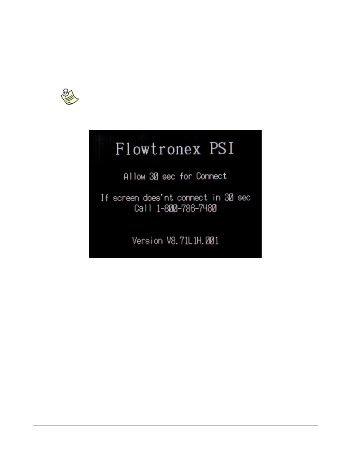
When power is applied to the pump station, the Flowtronex® PSI splash screen is briefly
displayed.
!
!
Note:
Two important items are displayed on the splash screen:
1) The number to call (1-800-786-7480) if you are experiencing problems
2) the Version number (such as, V8.71L1H.001) of the software.
!
!
!
!
After a brief warm up period, the first Master Control Interface (MCI) status screen is displayed, that
gives an overview of station operation, including Pressure, Main Flow, and Speed (VFD RPM) for the
station.
Page 6
© 2013 Flowtronex
2
Omron Touch-Screen Display
!
!
!
!
!
!
!
This screen also shows several features of the Master Control Interface (MCI) screens.
!
·
Press any touch key, such as Status Mode 1 and Graph, to view or edit parameters.
!
·
Use the up arrow key (▲) and the down (▼) arrow keys to view the next or previous screen
in a series.
!
!
Note:
When there are a series of screens, they are organized like the address list on a cell
phone. It may be faster to go in the opposite direction to reach a particular screen.
For example, if there are five screens in a series, from page 1 it is faster to use the
up arrow key to go to page 5 than it is to move down through four screens.
!
!
·
If available, tap on the Help key to open the help information screens.
!
·
Available on most screens, tap the Main Menu key to go directly to the Main Menu that acts as a
portal to other parts of the MCI application.
!
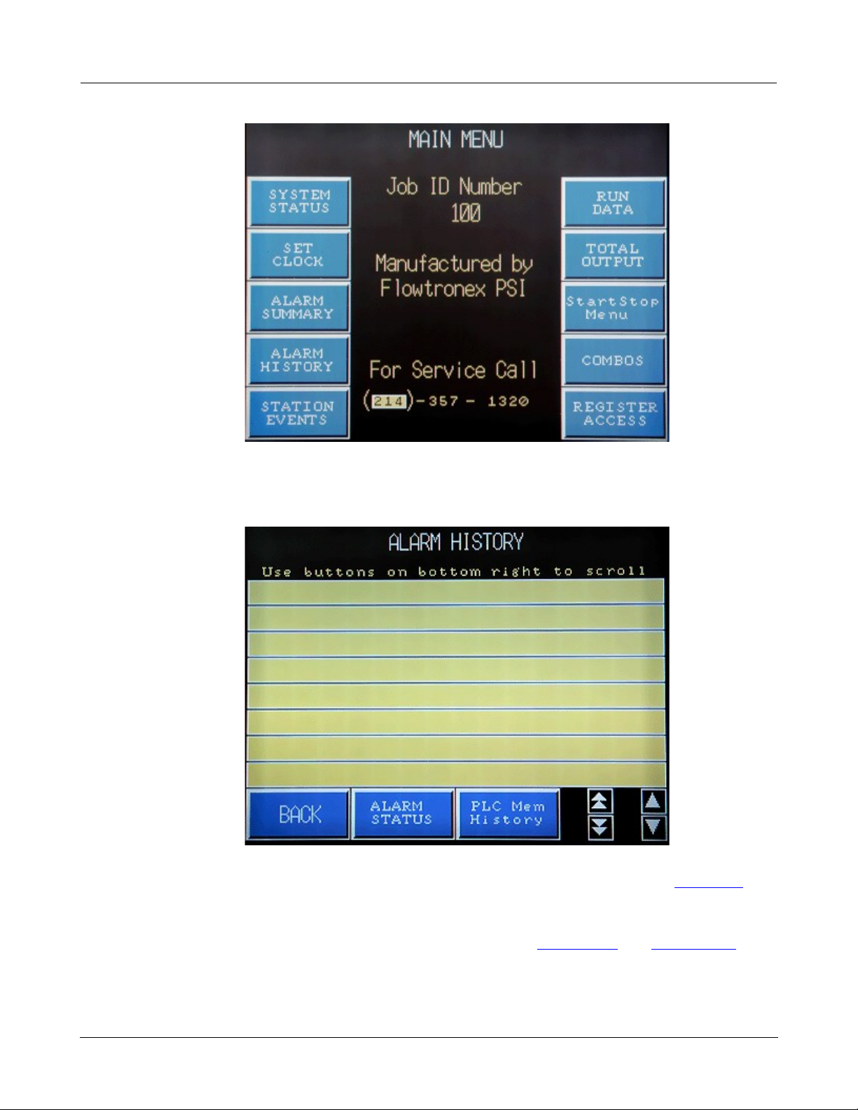
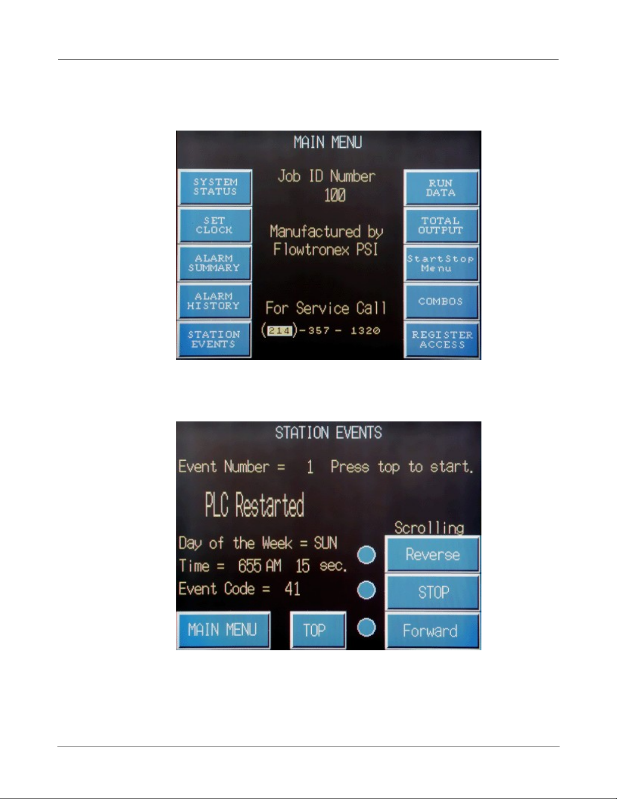
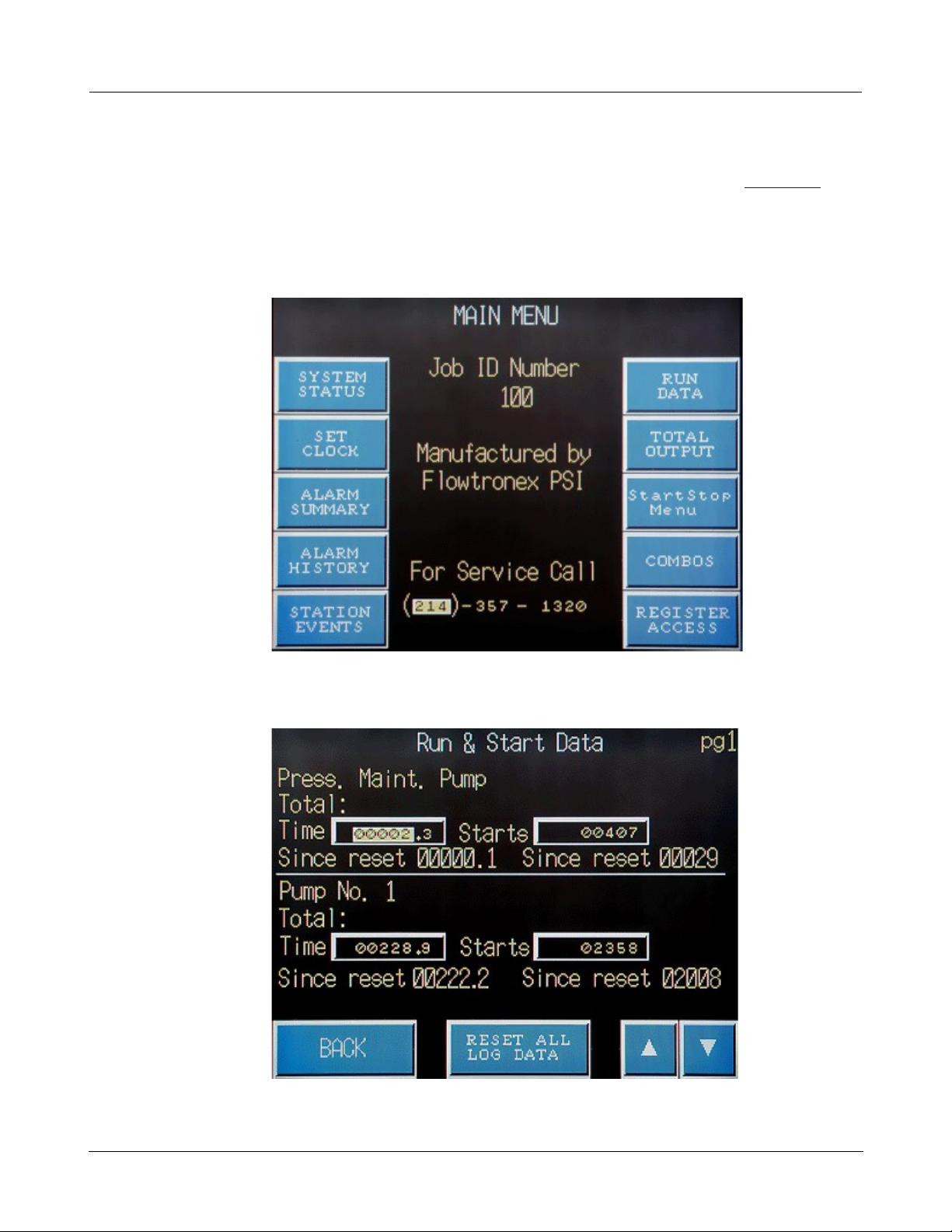
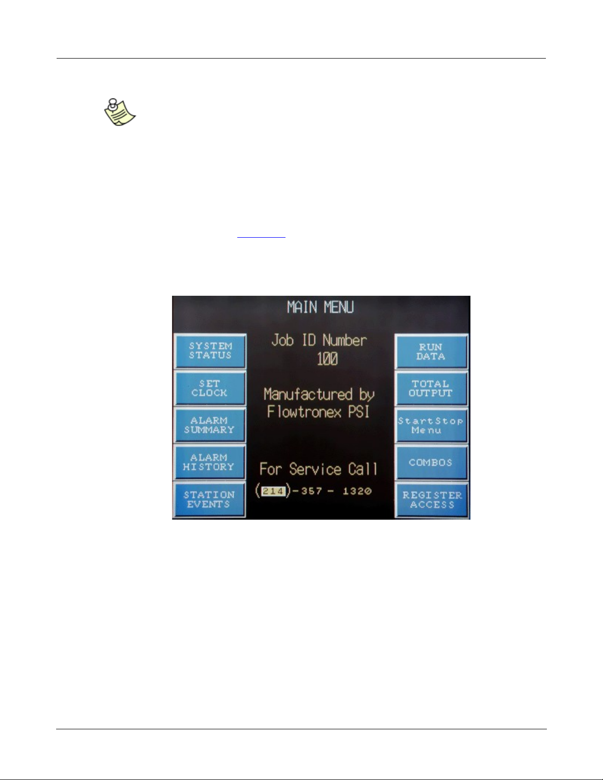
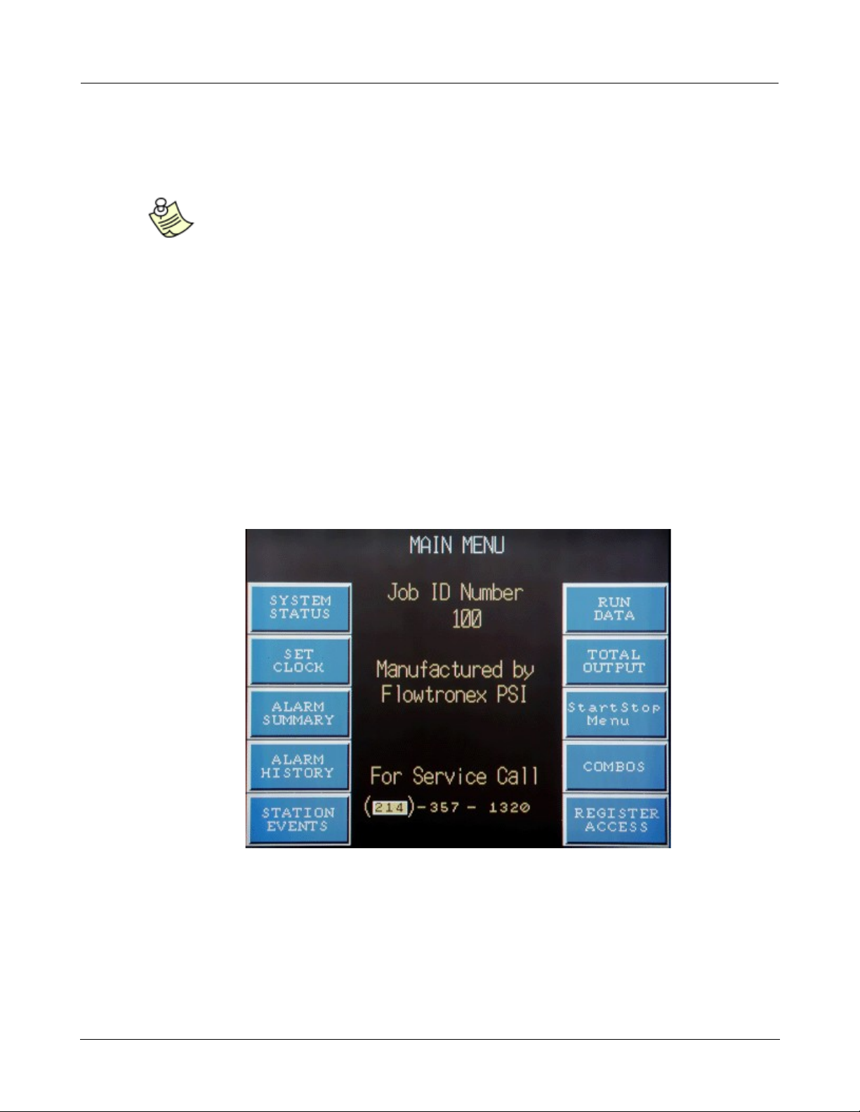
1.1 Main Menu
!
The Main Menu touch screen displays ten touch keys, your station's Job ID Number, and a number to
call for service. The features and characteristics of the different sections and screens are described in
the following sections under Basic Navigation.
Page 7

© 2013 Flowtronex
Basic Navigation
3
!
!
!
!
!
!
!
·
Press one of the ten touch keys to access information screen(s).
!
– System Status
!
– Set Clock
!
– Alarm Summary
!
– Alarm History
!
– Station Events
!
– Run Data
!
– Total Output
!
– Start Stop Menu
!
– Combos
!
– Register
Access
!
!
Note:
Certain functions are password protected and can only be accessed by a certified
Flowtronex® technician. If you press a touch key and the screen doesn't open, then
it is not available to the end user.
!
1.1.1 System Status
!
When the System Status key is pressed on the Main Menu, the first System Status screen is
displayed.
Page 8
© 2013 Flowtronex
4
Omron Touch-Screen Display
!
!
!
!
!
!
!
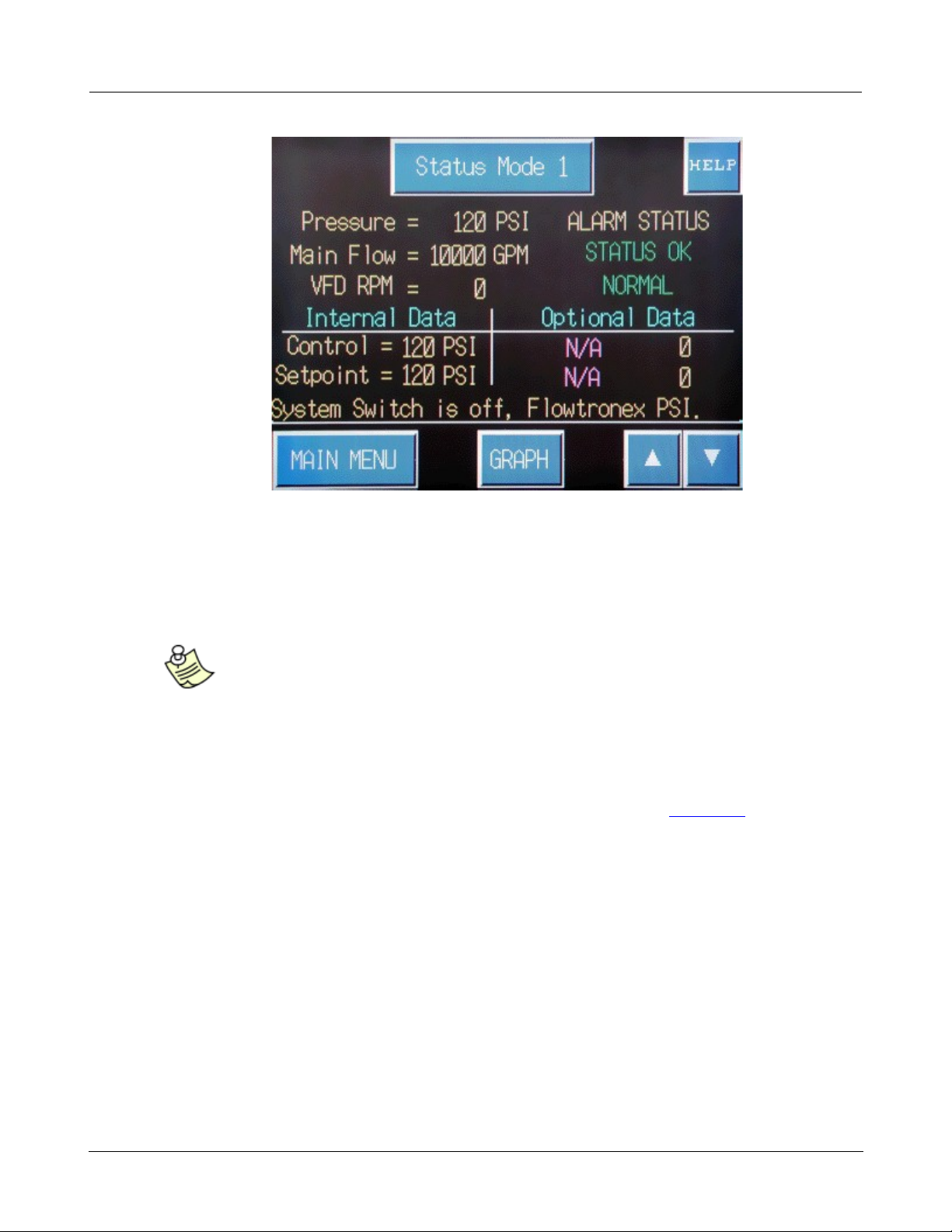
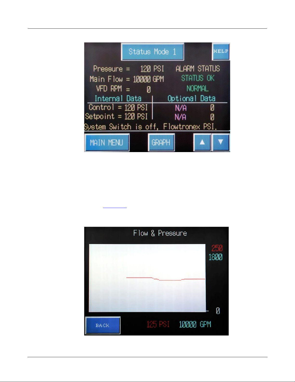
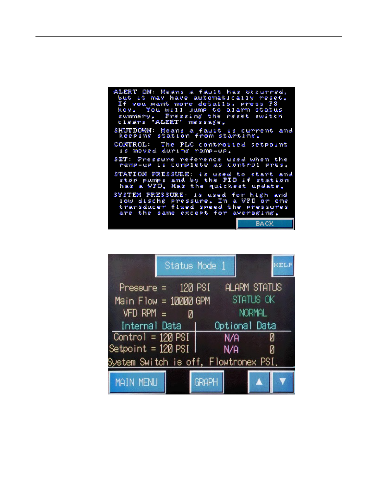
The first system status screen gives an overview of the operational status of the station. Pressure,
Main Flow, and VFD RPM (Speed) are displayed on the top of the screen along with the Alarm or fault
status. In the middle, the Control and Setpoint PSI are displayed along with other Optional Data if
programmed for your station. The final line shows if the enclosure System Switch setting: On, Off, or
Auto.
!
·
Optionally, press the Status Mode 1 key to refresh the screen.
!
·
Optionally, press the Main Menu touch key to return to the Main menu.
!
·
Press the Graph touch key to view the Flow & Pressure graph.
!
!
Page 9
© 2013 Flowtronex
Basic Navigation
5
!
!
!
!
!
·
Press the Back touch key to return to System Status 1 screen.
!
·
Optionally, press the Help touch key on the System Status screen to view the following information
screen.
!
!
!
·
Press the Back key to return to the first System Status screen.
!
!
!
·
Press the up arrow (▲) or down key (▼) on the first System Status screen to advance to
the second system status screen.
Page 10
© 2013 Flowtronex
6
Omron Touch-Screen Display
!
!
!
!
!
!
!
·
Optionally, press the up arrow (▲) to return to the previous status screen (that is, the System
Status 1 screen).
!
·
Optionally, press the Main Menu touch key to return to the Main menu.
!
·
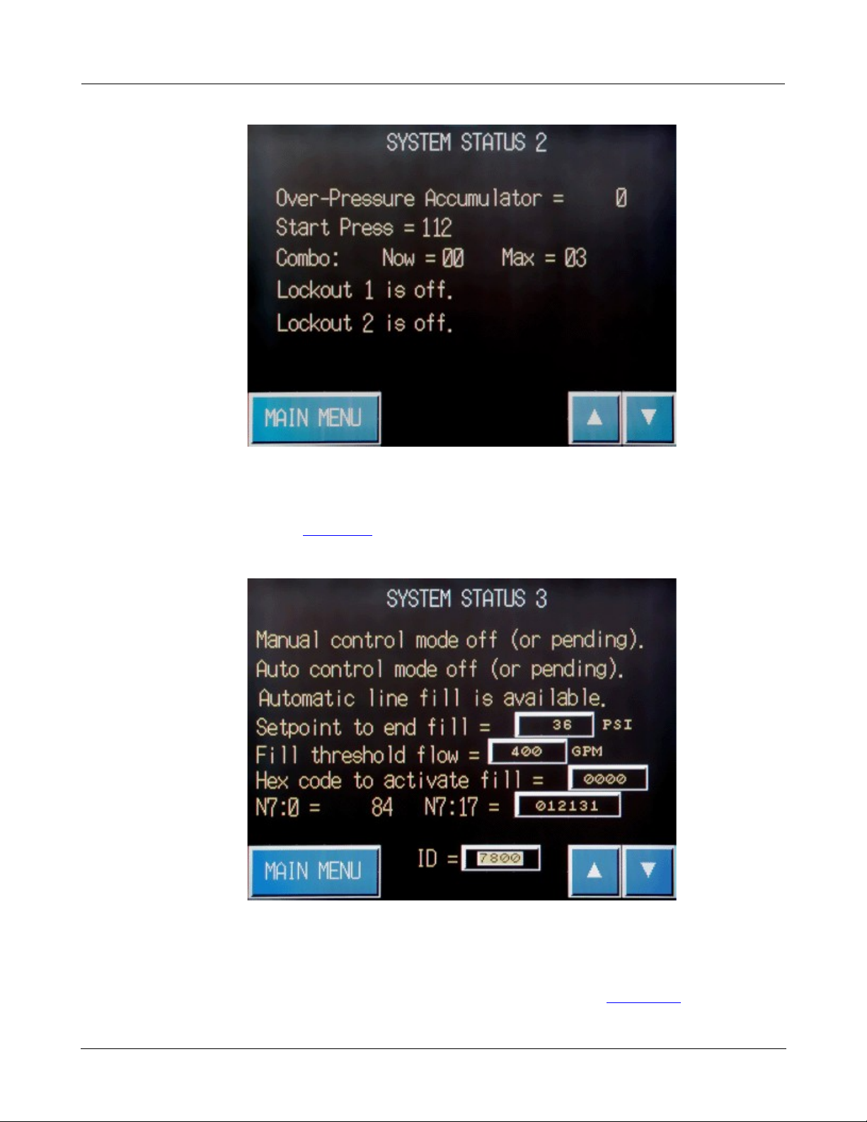
Press the down arrow (▼) to advance to the System Status 3 screen.
!
!
!
·
Optionally, press the up arrow (▲) to return to the System Status 2 screen
!
·
Optionally, press the down arrow (▼) to display to the first System Status screen.
!
·
Press the Main Menu touch key to return to the Main Menu (See also, Main Menu).
Page 11
© 2013 Flowtronex
Basic Navigation
7
!
!
!
!
1.1.2 Set Clock
!
You can access the Set Clock screen by pressing the Set Clock touch key on the Main Menu.
!
!
!
Use the Set Clock screen to set the time on the PLC.
!
!
!
·
Tap each value for Day, Month, Year, Hours, Minutes, or Seconds to pop open the
calculator/keypad and enter value on the Set Clock screen.
Page 12
© 2013 Flowtronex
8
Omron Touch-Screen Display
!
!
!
!
!
!
!
– Tap the numeric keys, 0 to 9 to enter a value.
!
– Tap the Enter key to have number entered as a value on the displayed screen.
!
– Tap Clr to close popup and return to the displayed screen .
!
·
Optionally, tap the Main Menu key to return to the Main Menu. (See also, Main Menu and Set
Clock in the How Do I? section.)
!
·
Optionally, tap System Status to return to the System Status 1 screen (See also, System Status.)
!
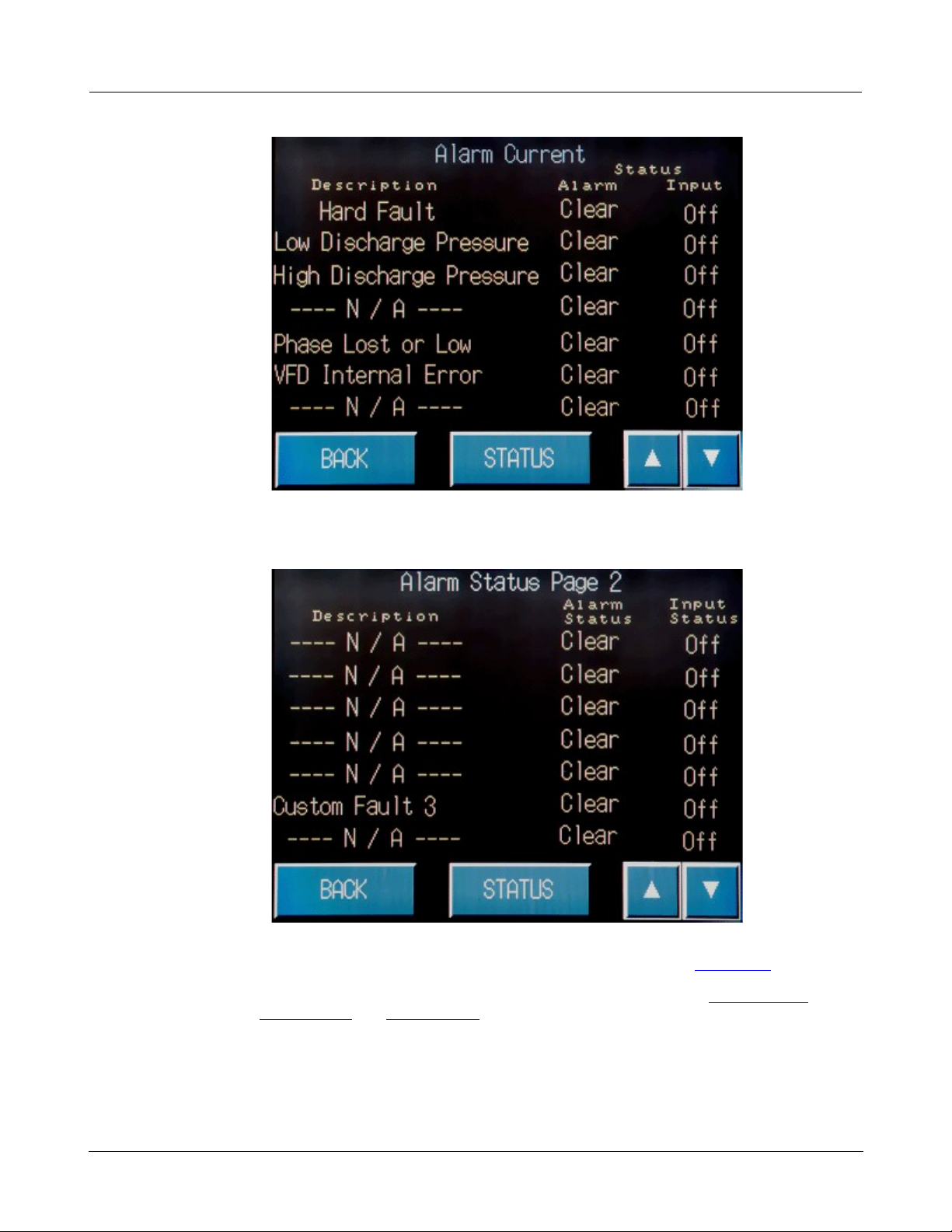
1.1.3 Alarm Summary
!
The alarm summary consists of one screen, Alarm Status, and is accessed by pressing Alarm
Summary from the main menu screen.
!
!
!
·
Tap the Alarm Summary key on the Main Menu to view a list of all current unacknowledged
alarms on the Alarm Current screen.
Page 13
© 2013 Flowtronex
Basic Navigation
9
!
!
!
!
!
!
!
·
Navigate the Alarm Current screen by tapping the down arrow (▼) key to display Alarm
Status page 2.
!
!
!
·
Optionally, tap the Back key to return to the Main Menu screen. (See also, Main Menu.)
!
·
Optionally tap the Status key to display the System Status screen (See also, System Status.)
(See also, Alarm History and Reset Alarms in the How Do I? section.)
!
1.1.4 Alarm History
!
The Alarm History screen can be accessed either from the Main Menu by tapping the Alarm History
key, or on the Alarm Summary screen by tapping the Alarm History key.
Page 14
© 2013 Flowtronex
10
Omron Touch-Screen Display
!
!
!
!
!
!
!
This screen displays the last alarms or faults in sequence, with the most recent fault listed first. This
screen is useful when you have experienced a system hard fault (the same fault occurred 3 times in a
one hour period).
!
!
!
·
Optionally, press the Main Menu key to return to the Main Menu screen (See also, Main Menu.)
!
·
Optionally, navigate the Alarm History screen and the Alarm Status screen by tapping the single
up (▲) or down arrow (▼) key to scroll one line at a time, or the double up or down arrow to
move to the very first line or last line of the list. (See also, Alarm Status and Reset Alarms in the
How Do I? section.)
!
·
Tap the Alarm Status key to view the Alarm Status screen and view a list of the current
unacknowledged alarms.
Page 15

© 2013 Flowtronex
Basic Navigation
11
!
!
!
!
!
!
!
·
Optionally, press the Back key to return to the Main Menu.
!
·
Tap the Alarm History key to return to the Alarm History screen.
!
·
On the Alarm History screen, press PLC Mem History key to view the Alarm History (PLC
Memory) screen. This screen shows you the status of all faults.
!
!
!
·
Optionally, press the up (▲) or down arrow (▼) to display Alarm Status screen (shown above).
!
·
Optionally, press the Status key to return to the first System Status screen, or press the up (▲)
arrow key .
!
·
Press the Back key to return to the Main Menu screen (See also, Main Menu.)
Page 16
© 2013 Flowtronex
12
Omron Touch-Screen Display
!
!
!
!
1.1.5 Station Events
!
The Station Events screen can be accessed from the Main Menu by pressing the Station Events key.
!
!
!
This screen is useful for seeing when pumps turned on or off, and can be used for troubleshooting
pump cycle faults. Stations events include such items as PLC Restart, Pressure Maintenance Pump
Stopped or 2nd Main Pump Started.
!
!
!
·
Optionally, press the Top touch key to start the automatic scrolling function that returns you to the
top of the page. As shown above, the Event Number = 1 and the instruction Press top to start is
displayed.
!
·
Optionally, press the Stop touch key to stop scrolling.
Page 17
© 2013 Flowtronex
Basic Navigation
13
!
!
!
!
!
·
Optionally, press the Reverse or Forward key to scrolling in that direction.
!
·
Optionally, press the Main Menu touch key to return to the Main Menu. (See also, Main Menu.)
!
1.1.6 Run Data
!
The seven Run Data screens can be accessed from the Main Menu by pressing the Run Data touch
key.
!
!
!
The Run & Start Data screens show you all of your pump hours. You can edit the Time and Starts data
on the Run & Start Data page 1 for the PM (Pressure Maintenance) Pump and Pump No. 1.
!
Page 18
© 2013 Flowtronex
14
Omron Touch-Screen Display
!
!
!
!
!
·
Press the Reset All Log Data touch key to reset the "since reset values for Total Time and Total
Starts". The Total Time and Total Starts displays the cumulative totals.
!
·
Navigate the Run Data screens by tapping the up (▲) and go to Run & Start Data page 7, or
the down arrow (▼) to display the Run Data screen page 2.
!
!
!
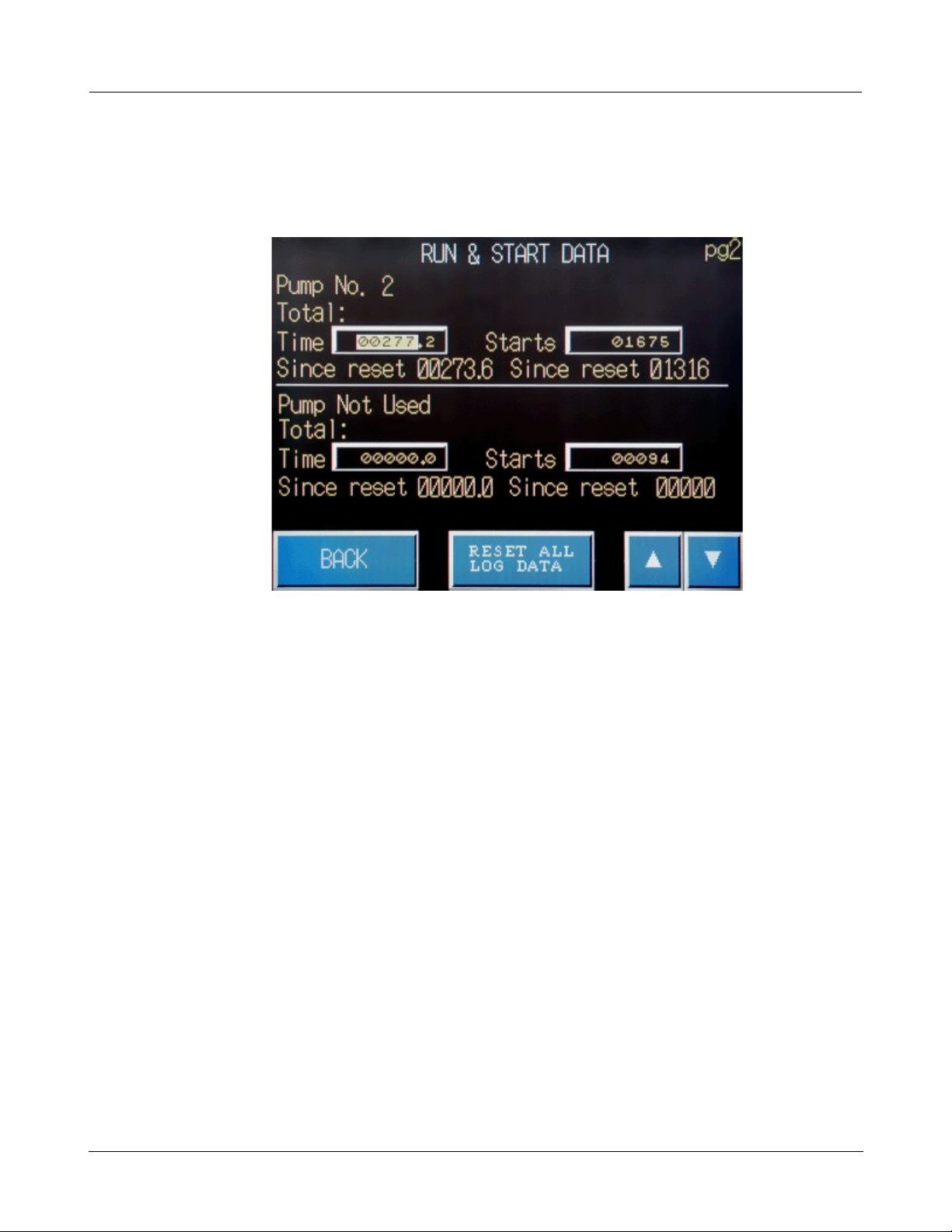
You can edit the Time and Starts data on the Run & Start Data page 2 for Pump No. 2. If multiple
pumps are used, Pump No. 3 data is also shown, or else Pump Not Used is displayed.
!
·
Optionally, press Back to return to the Main Menu.
!
·
Optionally, press Reset All Log Data Key to reset the runtime totals.
!
·
Press the up (▲) to display the previous Run & Start Data screen 1, or press the down arrow
(▼)
touch key to display the next Run & Start Data screen 3.
Page 19
© 2013 Flowtronex
Basic Navigation
15
!
!
!
!
!
!
!
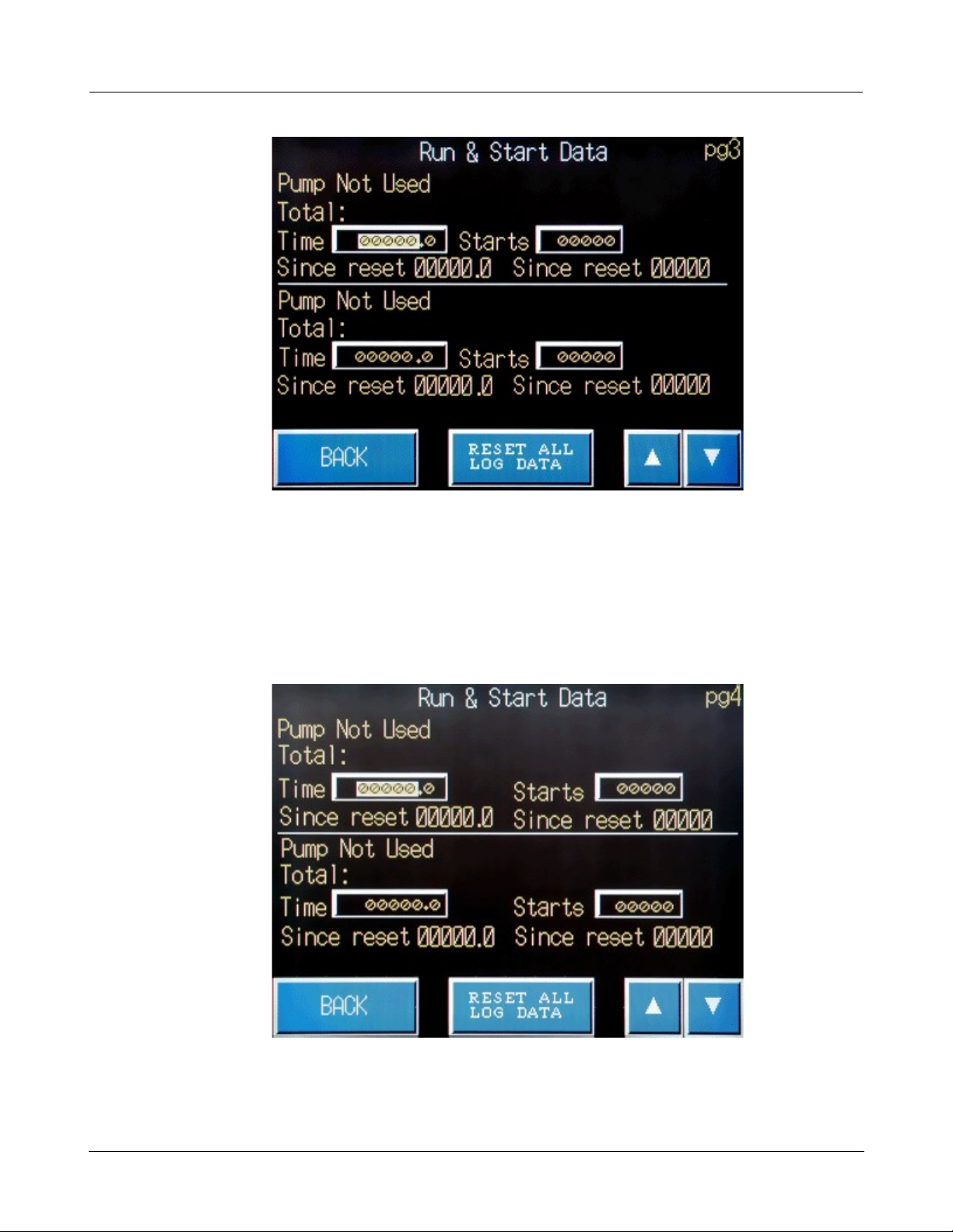
You can edit the Time and Starts data if multiple pumps are used on the Run & Start Data page 3 , or
else Pump Not Used is displayed.
!
·
Optionally, press Back to return to the Main Menu.
!
·
Optionally, press the Reset All Log Data Key to reset the runtime totals.
!
·
Press the up (▲) to display the previous Run & Start Data screen 2, or press the down arrow
(▼)
touch key to display the next Run & Start Data screen 4.
!
!
!
You can edit the Time and Starts data if multiple pumps are used on the Run & Start Data page 4 , or
else Pump Not Used is displayed.
Page 20
© 2013 Flowtronex
16
Omron Touch-Screen Display
!
!
!
!
!
·
Optionally, press Back to return to the Main Menu.
!
·
Optionally, press the Reset All Log Data Key to reset the runtime totals.
!
·
Press the up (▲) to display the previous Run & Start Data screen 3, or press the down arrow
(▼)
touch key to display the next Run & Start Data screen 5.
!
!
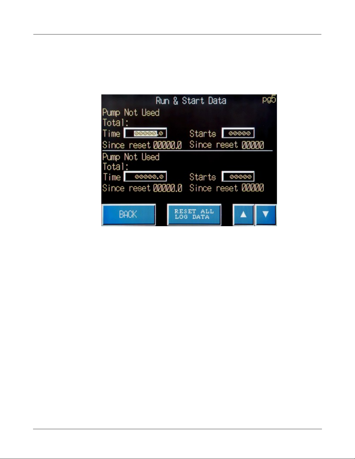
!
You can edit the Time and Starts data if multiple pumps are used on the Run & Start Data page 4, or
else Pump Not Used is displayed.
!
·
Optionally, press Back to return to the Main Menu.
!
·
Optionally, press the Reset All Log Data Key to reset the runtime totals.
!
·
Press the up (▲) to display the previous Run & Start Data screen 6, or press the down arrow
(▼)
touch key to display the next Run & Start Data screen 6.
Page 21
© 2013 Flowtronex
Basic Navigation
17
!
!
!
!
!
!
!
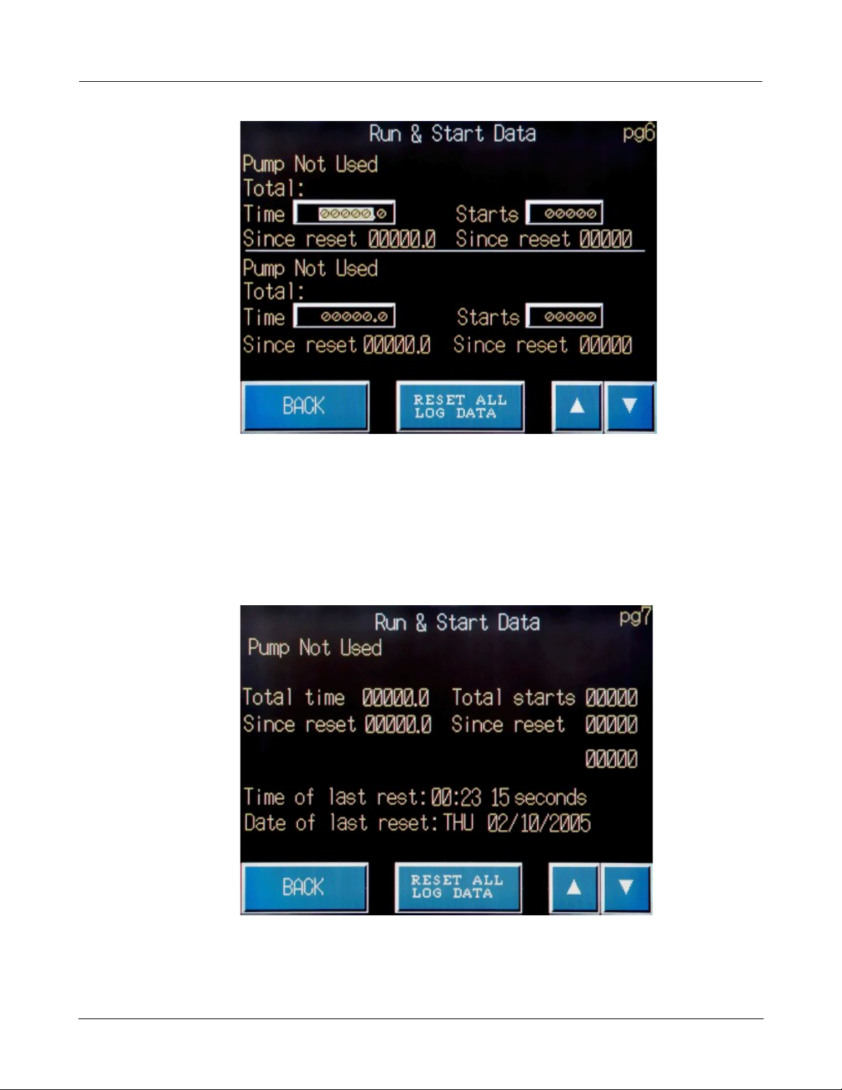
You can edit the Time and Starts data if multiple pumps are used on the Run & Start Data page 6, or
else Pump Not Used is displayed.
!
·
Optionally, press Back to return to the Main Menu.
!
·
Optionally, press the Reset All Log Data Key to reset the runtime totals.
!
·
Press the up (▲) to display the previous Run & Start Data screen 5, or press the down arrow
(▼)
touch key to display the next Run & Start Data screen 7.
!
Page 22
© 2013 Flowtronex
18
Omron Touch-Screen Display
!
!
!
!
!
!
Note:
The Reset All Log Data touch key is the same as the Reset touch key. Pressing
either key on any page resets the Since Reset values for Total Time and Total
Starts.
!
!
You can edit the Time and Starts data if multiple pumps are used on the Run & Start Data page 7, or
else Pump Not Used is displayed. The last page (Run & Start Data pg7) also displays the time and
date of the last system reset.
!
·
Optionally, press the Reset All Log Data Key to reset the runtime totals.
!
·
Press Back to return to the Main Menu.
!
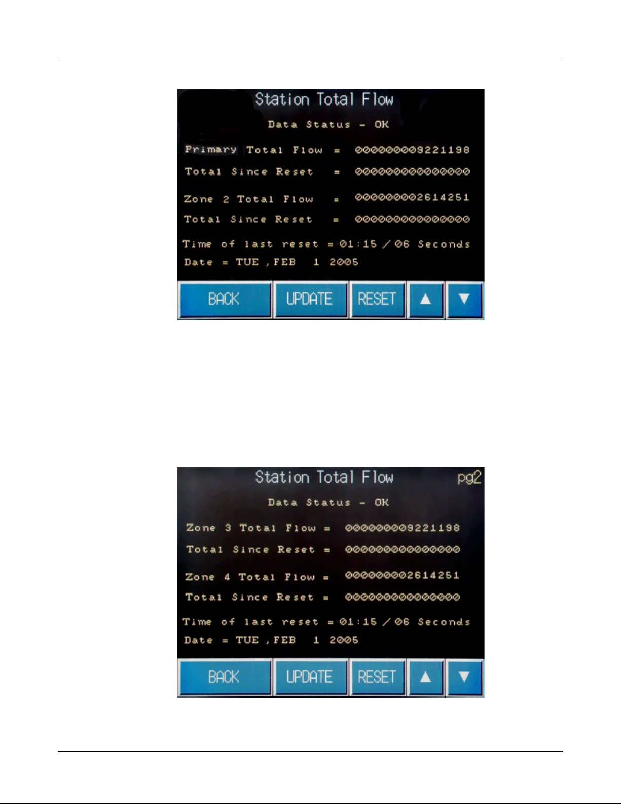
1.1.7 Total Output
!
The Total Output screens can be accessed from the Main Menu.
!
!
!
·
Press the Total Output touch key and display the Station Total Flow screen.
Page 23
© 2013 Flowtronex
Basic Navigation
19
!
!
!
!
!
!
!
The values initially displayed for the flow totals are from the last time that this screen was
accessed
and
updated. This page is also used to view a second flow rate and total if your station is so equipped.
Both pages allow you to view the time and date of the last reset.
!
The Station Total Flow page 1 screen is read-only. Total Flow information shown is fed directly from
the PLC for the Primary Total Flow and Zone 2.
!
·
Press Update touch key to update values from the PLC.
!
·
Press the down arrow (▼) in the bottom right corner of the screen to display to the second Station
Total Flow screens.
!
!
!
The Station Total Flow page 2 screen displays read-only, Total Flow information fed directly from the
Page 24
© 2013 Flowtronex
20
Omron Touch-Screen Display
!
!
!
!
!
PLC for Zone 3 and 4.
!
·
Press Update touch key to update values from the PLC.
!
!
Note:
Always press the Update touch key. This will accomplish two functions. It will grab
the current values from the PLC, and it continuously updates the values while this
screen is open.
!
Be very careful about pressing the Reset touch key, as it resets all four flows (if
your station is so equipped). If you have more than two flows, it is recommended
that you advance to the second page before pressing the Reset touch key.
!
!
·
Optionally, press the Reset touch key to reset the values. (See note above).
!
·
Optionally, press Back to return to the Main Menu.
!
·
Press the up arrow (▲) in the bottom right corner of the screen to return to the first Station Flow
Total
screen.
!
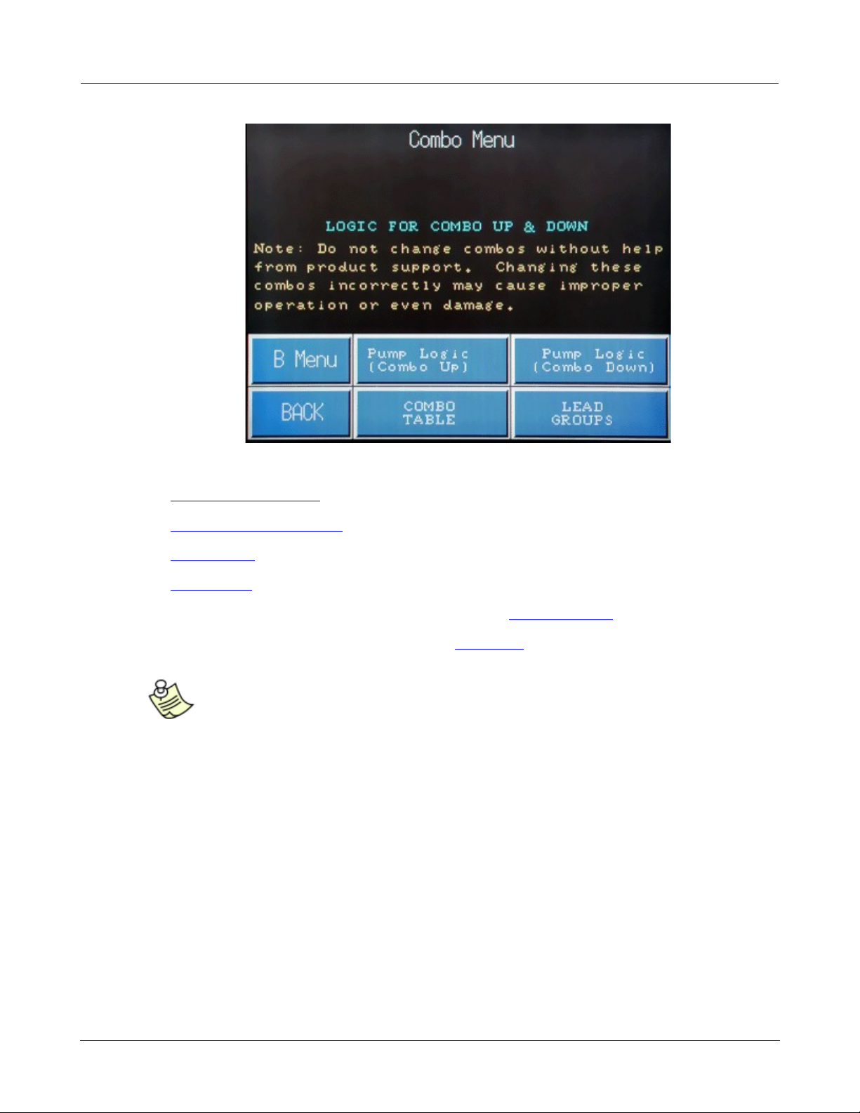
1.1.8 Start Stop Menu (Combo Menu)
!
Access the Combo Menu by pressing the StartStop key on the Main Menu.
!
!
!
·
Tap the StartStop Menu key on the Main Menu to display the Combo Menu Screen.
Page 25
© 2013 Flowtronex
Basic Navigation
21
!
!
!
!
!
!
Tap one of the following keys on the Combo Menu:
!
·
Pump Logic (Combo Up)
!
·
Pump Logic (Combo Down)
!
·
Combo Table
!
·
Lead Groups.
!
·
Optionally, press the B Menu touch key to return to the B Register Menu screen.
!
·
Optionally, press the Back key to return to the Main Menu.
!
!
Note:
Contact Product Support before attempting to changes any combos. Improper
settings can result in damage to your pumping stations or operational failure
!
!
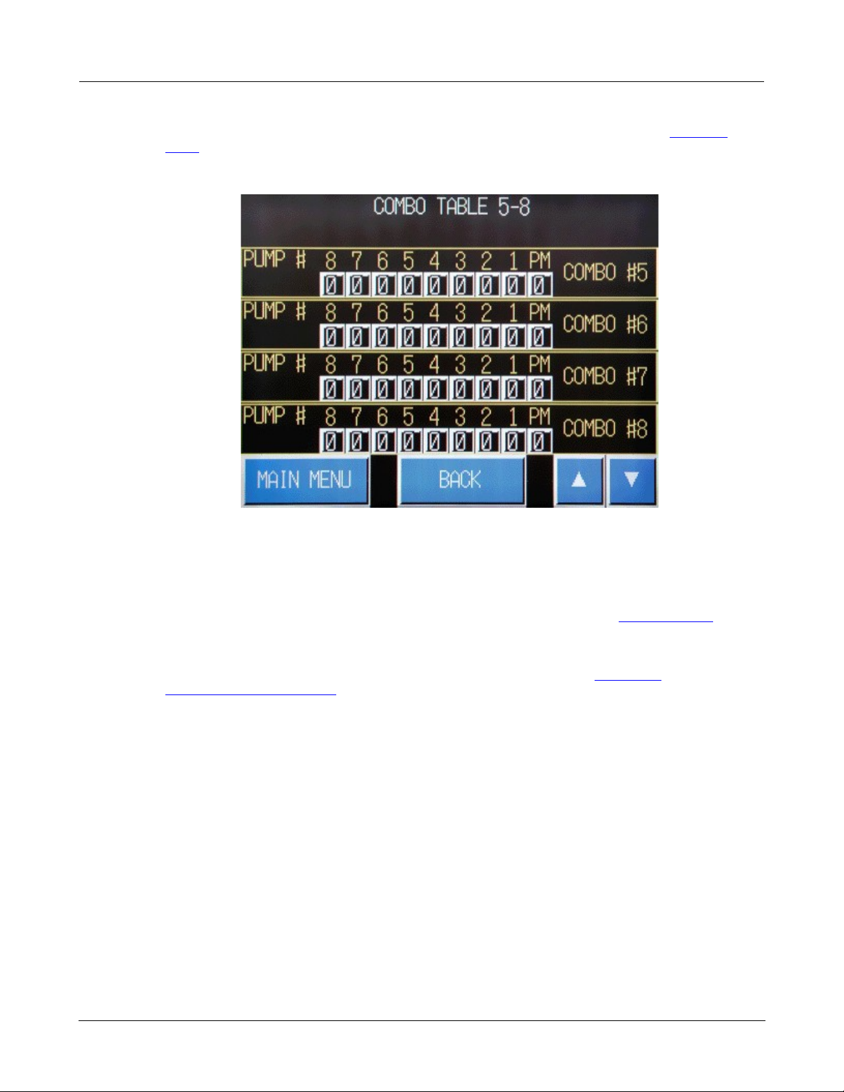
1.1.9 Combos
!
You can display and view the Combo Tables by pressing the Combos key on the Main Menu menu.
The Combo Tables show the pumps assigned to a Combo group (numbered 1 through 8).
Page 26
© 2013 Flowtronex
22
Omron Touch-Screen Display
!
!
!
!
!
!
!
There are two Combo Tables, Combo Table 1-4 and Combo Table 5-8.
!
!
!
The Combo Table is actually a grid with the Combo numbers (Combo #1 to Combo #4) shown on the
right side and the pump numbers (PM and 1-8) shown on the top. The white boxes below the pump
numbers are enabling bits that show if the pump is enabled or disabled. As shown on the screen
above, a one (1) indicates the pump is enabled and a zero (0) shows the pump is not enabled in the
combo group.
For example, Combo #1 above has only the PM pump enabled. In Combo #2, only Pump #2 is
enabled and the PM pump is disabled for this combo. Combo #3 has Pumps #1,# 2, and #3
available and the PM pump is not enabled.
!
·
Optionally, press the Main Menu touch key to return to the Main Menu. (See also, Main Menu.)
Page 27
© 2013 Flowtronex
Basic Navigation
23
!
!
!
!
!
·
Optionally, press the Combo Menu key to view the Combo Menu screen. (See also StartStop
Menu).
!
·
Optionally, press the down (▼) arrow to display Combo Table 5-8 screen.
!
!
!
No pumps are enabled for Combo #5 to #8 shown on the second Combo Table screen.
!
·
To enable a pump, tap on the zero field and a green one is displayed. The number toggles
between a zero (0) and a one (1).
!
·
Optionally, press the Back key to view the Combo Menu screen. (See also StartStop Menu).
!
·
Optionally, press the up (▲) arrows to display Combo Table1-4 screen.
!
·
Press the Main Menu touch key to return to the Main Menu. (See also, Main Menu.) See also
Change Combo Parameters.
Page 28
© 2013 Flowtronex
24
Omron Touch-Screen Display
!
!
!
!
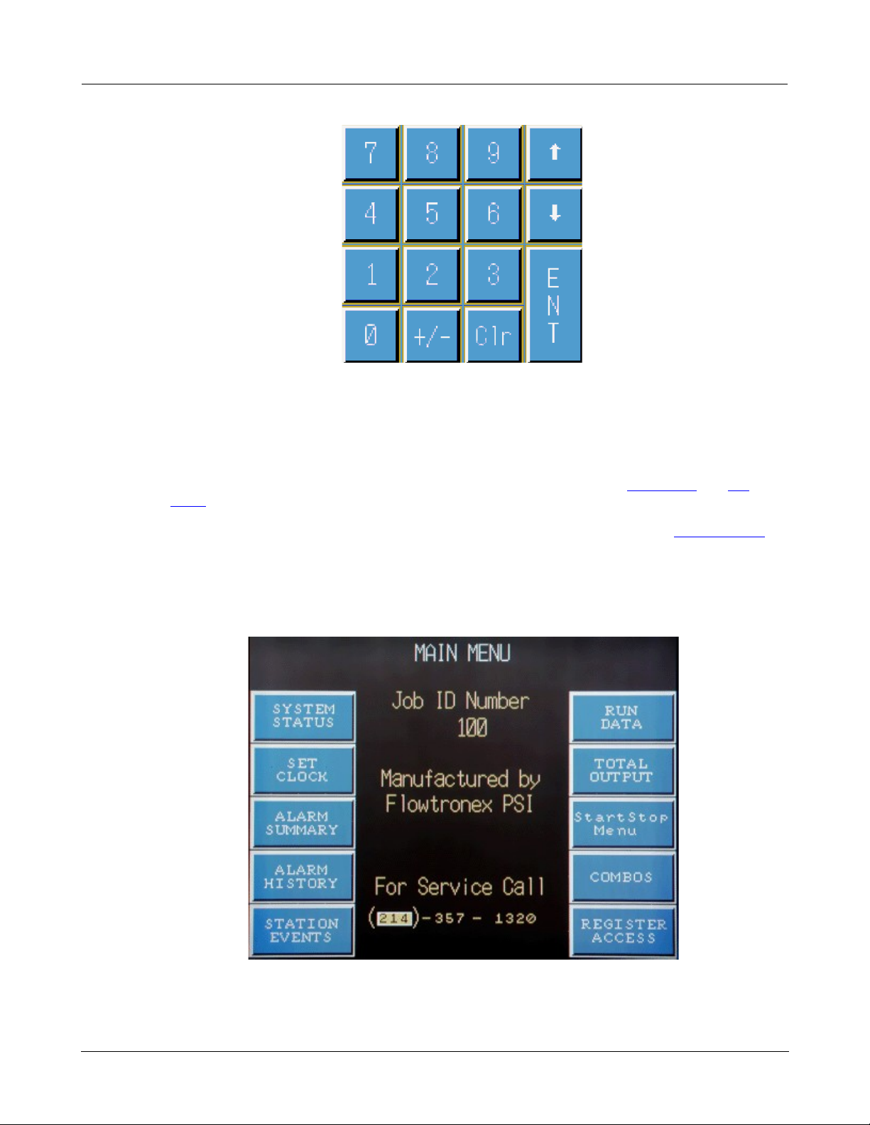
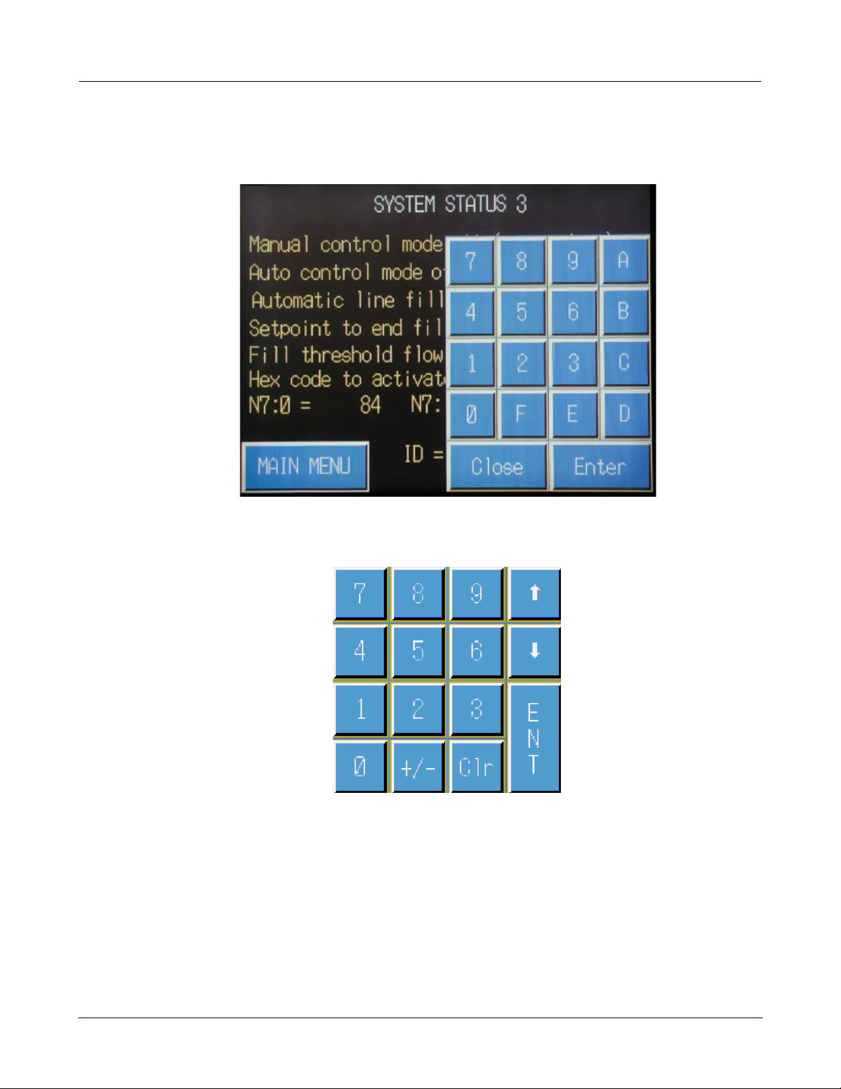
1.2 Calculator/Keypad
!
The calculator/keypad pops over the displayed screen when you tap on an editable value field.
!
!
!
·
Generally, the calculator/keypad, shown below is displayed. When needed, such as when entering
hex numbers, the alphanumeric keypad shown above is displayed.
!
!
!
·
Tap and hold stylus in a blank field to display the appropriate keypad popup screen.
!
– Tap the 0 to 9 (or if displayed, A through F) keys to enter a value.
!
– Tap up arrow
(↑)
or down arrow (↓) to move to the next field for entry.
!
– Tap the ENT or Enter key to have number entered as a value on the displayed screen.
!
– Tap Clr or Close to close popup and return to the displayed screen.
!
– Tap +/- key on the calculator/keypad to toggle the number selected to a positive or negative. If
the selected number is currently positive (such as, 23), tap on the +/- key to make it a negative
Page 29

© 2013 Flowtronex
Basic Navigation
25
!
!
!
!
!
number (such as, –23).
!
1.3 Password Protected Screens
!
The display has certain functions or screens that are password protected and can only be accessed by
a certified Flowtronex® technician (or end users if a passwords is provided). If you press a touch key
and the screen doesn't open, it is not available to the end user. These password-protected screens
are listed below.
!
§ Combos Up/Down
!
§ Combos
!
§ PID Tuning
!
§ Calibration
!
§ Start/Stop Features
!
§ Calibration (analog)
!
§ I/O Control Data
!
§ Totalizers
!
§ N99 Config and ID
!
§ Datalogging Control N104:xx
!
§ B3:xx Mode, Max Speed, and Jockey Cycle
!
§ B40:xx Combos
!
§ B60:xx Pump & Accessory Definitions
!
!
Note:
The end user should call Flowtronex® Product Support (1-800-786-7480) to
determine whether access is required and/or authorized.
!
!
The functionality of these screens is discussed in the "How Do I?" section of this manual (See also,
How Do I?.) This allows the Flowtronex® technician to utilize this manual. Also, if Product Support
determines an End Users needs to access these screens, they can provide users with an access
Password.
!
1.4 Register Access
Menus
!
The Register Access screen is displayed when you press the Register Access touch key on the Main
Menu.
Page 30
© 2013 Flowtronex
26
Omron Touch-Screen Display
!
!
!
!
!
!
!
The different screens and their functions accessed from the Register Access screen are discussed in
the How Do I section of this manual. (See also, How Do I?.)
!
!
!
The Register Access screen displays ten touch keys:
!
!
·
N20 &N21 Combo & Auxiliary Setpoints
·
N20 & N23 VFD Bypass
!
·
N70 & N71 Safeties
·
N23 Flow Stop
!
·
N7 XXX PID Tuning
·
Auto Lake Screen, Lake Fill & Filter
!
·
Timer Access
·
N Register Menu
Page 31

© 2013 Flowtronex
Basic Navigation
27
!
!
!
!
!
!
·
Lockout Settings
·
B Register Menu
!
·
Optionally, press the Main Menu touch key to return to the Main Menu. (See also, Main Menu.)
!
!
Note:
If you press a touch key and the screen doesn't open, it is not available to the end
user. See also, Password Protected Screens.
!
!
1.4.1 N Register Menu Key
!
Press the N Register Menu key on the Register Access Screen to open the N Register screen:
!
!
!
On the N Register Access menu, press one of the following keys:
!
!
·
Calibration
·
I/O Control Data
·
I/O Buffers
N51:xx
!
·
Start/Stop Features
·
More N7 Regs Misc.
Control
·
Datalogging Control N104:
xx
!
·
Custom Features
·
Totalizers
·
Back
!
·
Pulse Flowmeter Data
·
Interchange Groups
!
·
Main Menu
·
N99 Config And ID
!
!
!
Note:
If you press a touch key and the screen doesn't open, it is not available to the end
user. See also, Password Protected Screens.
Page 32

© 2013 Flowtronex
28
Omron Touch-Screen Display
!
!
!
!
1.4.2 B Register Menu Key
!
Press the N Register Menu key on the Register Access Screen to open the N Register screen:
!
!
!
On the B Register Access menu, press one of the following keys:
!
!
·
B3:xx Mode, Max Speed & Jockey Cycle
·
B85:xx Booster Pump Definitions
!
·
B40:xx Combos
·
B90:xx Timed Pump Definitions
!
·
B60:xx Pump & Accessory Definitions
·
B41:xx Pump Outputs
!
·
Main Menu
·
Back
!
!
!
Note:
If you press a touch key and the screen doesn't open, it is not available to the end
user. See also, Password Protected Screens.
!
!
!
2.0 How Do I?
!
The "How Do I?" section of the manual gives you step-by-step instruction to view and edit the pump
station's system parameters. Certain screens are password protected and can only be accessed by a
certified Flowtronex® technician. In some instances, end users may be given a password to access
and change certain functions under the direction of a technician or Product Support representative.
Follow the directions for changes given by these authorized personnel. Damage or malfunction of your
station could result if information entered is not correct. If you press a touch key and the screen
doesn't open, it is not available to an end user.
Page 33

© 2013 Flowtronex
How Do I?
29
!
!
!
!
2.1 Set Clock
!
You can access the Set Clock screen by pressing the Set Clock touch key on the Main Menu.
!
·
Press the Set Clock touch key on the Main Menu to open the Set Clock screen and set the time
on the PLC.
!
!
!
·
Tap on any of the value fields to open the pop-over calculator/keypad and change the values for
Day and Time. (See also, Calculator/Keypad.).
!
·
Press the System Status key to return to the Main Menu. (See also, System Status.)
!
·
Press the Back key to return to the Main Menu. (See also, Main Menu.)
!
2.2 Reset Alarms
!
Use the Reset button on the enclosure door to reset faults and alarms.
!
!
Note:
The Master Control Interface (MCI) only displays the status of alarms—it does not
clear them.
!
!
Keep in mind, the Low Discharge Pressure switch in the door can be placed in Override, allowing the
pump station to run, build pressure, and remove the Low Discharge Pressure Fault. In the case of a
VFD fault, the fault must be cleared by cycling the power off and on.
!
If a fault or alarm does not reset, the fault is still present. Further troubleshooting and repair must be
performed. Contact Flowtronex® Product Support for further instructions.
Page 34

© 2013 Flowtronex
30
Omron Touch-Screen Display
!
!
!
!
2.3 Change Combo Parameters
!
You can define combo setpoints and parameters by pressing the Register Access touch key on the
Main Menu and opening the Register Access screen.
!
!
!
·
Press the N20 & N21 Combo & Auxiliary Setpoints touch key on the Register Access screen to
open the first of three Combo setpoints screens.
!
!
·
Tap the value field next to any of these registers and the calculator/keypad pops-over the screen.
Enter or edit the value. (See also, Calculator/Keypad.)
!
– Enter the normal mode setpoint in PSI in the N20:0 register. A common setpoint is 120 PSI.
!
– Enter the maximum number of combos (1 to 8) normally used in the N20:1 register.
Page 35

© 2013 Flowtronex
How Do I?
31
!
!
!
!
!
– Enter the setpoint in PSI for Lockout #1 in the N20:3 register. A common setpoint is 120 PSI.
!
– Enter the maximum combo used for Lockout #1 in the N20:4 register.
!
– Enter the setpoint in PSI for Lockout #2 in the N20:5 register. A common setpoint is 120 PSI.
!
– Enter the maximum combo used for Lockout #1 in the N20:6 register.
!
·
Optionally, press the Main Menu touch key to return to the Main Menu. (See also, Main Menu.)
!
·
Optionally, press Back to return to the Register Access key.
!
·
Press the down arrow (▼) in the bottom right corner of the screen to open the next
screen, Combo setpoints page 2.
!
!
!
·
N21:3 defines the pressure below normal setpoint pressure when the first pump (usually the PM
pump, but not always) starts automatically.
!
·
N21:4 defines the time delay before the first pump starts, once the start pressure is reached. This
is normally set to 0.
!
For example, if your normal setpoint pressure is 120 PSI and you enter 10 in N21:3, the first
pump comes on at 110 PSI.
!
·
N21:5 defines the pressure above normal setpoint pressure when the first pump (usually the PM
pump, but not always) stops automatically.
!
For example, if your normal setpoint pressure is 120 PSI and you enter 5 in N21:5, the first
pump retires at 125 PSI.
!
Note:
If this is the first main pump, and it is controlled by a VFD, the value needs to be -2. If station
flow is less than 20 GPM, and the station pressure is at the normal setpoint (125 PSI in this
example), the PLC does a speed test to determine whether to shut the pump down. A speed test
means that the VFD slows down to minimum speed. If the station pressure remains at or above
Page 36

© 2013 Flowtronex
32
Omron Touch-Screen Display
!
!
!
!
!
the value entered in N21:9 (123 PSI in this example), then the pump is retired.
!
·
N21:6 defines the delay time before the first pump stops once the stop pressure is reached. This
is normally set to between 5 and 10 seconds.
!
·
N21:7 defines the pressure below normal setpoint pressure when the second pump (normally the
first main pump, but not always) will start automatically.
!
For example, if your normal setpoint pressure is 120 PSI and you enter 15 in N21:7, the second
pump comes on at 105 PSI.
!
·
N21:8 defines the delay time before the first pump starts, once the start pressure is reached. This
is normally set to 0.
!
·
Tap the value field next to any of these registers and the calculator/keypad pops-over the screen.
Enter or edit the value. (See also, Calculator/Keypad.)
!
·
To define combos 2 and 3+, press the down arrow (▼) in the bottom right corner of the screen
to display Combo setpoints page 3.
!
·
Optionally, press the Main Menu touch key to return to the Main Menu. (See also, Main Menu.)
!
·
Optionally, press Back to return to the Register Access screen.
!
!
!
·
N21:9 defines the pressure above normal setpoint pressure when the second pump (usually the
first main pump, but not always) will stop automatically.
!
For example, if your normal setpoint pressure is 120 PSI and you enter 5 in N21:9, the second
pump retires at 125 PSI.
!
Note:
If this is the first main pump, and it is controlled by a VFD, the value needs to be -2. If station
flow is less than 20 GPM and the station pressure is at the normal setpoint (125 PSI in this
example) the PLC does a speed test to determine whether to shut the pump down. A speed test
means that the VFD slows down to minimum speed. If the station pressure remains at or above
Page 37

© 2013 Flowtronex
How Do I?
33
!
!
!
!
!
the value entered in N21:9 (123 PSI in this example), ,then the pump is retired.
!
Note:
The second (and higher) main pump is normally not controlled by the VFD. Therefore, the value
in N21:13 is usually set to 30 PSI. In the case of multiple VFDs, the value would be -2.
!
·
N21:10 defines the delay time before the second pump stops, once the stop pressure is reached.
This is normally set to 10 seconds.
!
·
N21:11 defines the pressure below normal setpoint pressure when the third pump (normally the
second main pump, but not always) starts automatically.
!
For example, if your normal setpoint pressure is 120 PSI and you enter 15 in N21:11, the second
pump comes on at 105 PSI.
!
·
N21:12 defines the delay time before the third pump starts, once the start pressure is reached.
This is normally set to 0.
!
·
N21:13 defines the pressure above normal setpoint pressure when the third pump (usually the
second main pump, but not always) stops automatically.
!
For example, if your normal setpoint pressure is 120 PSI and you enter 5 in N21:13, the first
pump retires at 125 PSI.
!
Note:
The second (and higher) main pump is normally not controlled by the VFD. Therefore, the value
in N21:13 is usually set to 30 PSI. In the case of multiple VFDs, the value would be -2.
!
·
N21:14 defines the delay time before the third pump stops once the stop pressure is reached. This
is normally set to 90 seconds.
!
·
Tap the value field next to any of these registers and the calculator/keypad pops-over the screen.
Enter or edit the value. (See also, Calculator/Keypad.)
!
!
Note:
Use the values defined for combo 3 when the number of combos exceeds 3.
!
!
!
·
Optionally, press the Main Menu touch key to return to the Main Menu. (See also, Main Menu.)
!
·
Optionally, press Back to return to the Register Access screen.
!
·
Press press the down arrow (▼) in the bottom right corner of the screen to display
Combo setpoints page 4.
!
Three auxiliary setpoints can be used and set up on page 4, Aux Setpoints screen.
Page 38

© 2013 Flowtronex
34
Omron Touch-Screen Display
!
!
!
!
!
!
!
·
Define auxiliary setpoint #1 in the N20:7, Setpoint #2 in the N20:8, and Setpoint #3 in the N20:9.
All setpoint are in PSI.
!
·
Tap the value field next to any of these registers and the calculator/keypad pops-over the screen.
Enter or edit the setpoint value in PSI. (See also, Calculator/Keypad.)
!
·
Press the down arrow (▼) in the bottom right corner of the screen to display Combo
setpoints page 1.
!
·
Press the up arrow (▲) in the bottom right corner of the screen to display Combo setpoints page
3.
!
·
Optionally, press the Main Menu touch key to return to the Main Menu. (See also, Main Menu.)
!
·
Optionally, press Back to return to the Register Access screen.
!
2.4 Define Safety Parameters
!
You can access the Safeties register screens and define your safety parameters, faults, and alarms by
pressing the Register Access touch key on the Main Menu and opening the Register Access screen.
!
!
Note:
Please consult Flowtronex® Product Support before making any changes.
Significant damage to your station could potentially occur if safeties are disabled
by entering invalid values in these registers.
Page 39

© 2013 Flowtronex
How Do I?
35
!
!
!
!
!
!
!
·
Press the N70 & N71 Safeties touch key on the Register Access screen to display the first of three
Safety registers screens.
!
!
!
·
N71:0 defines your Low Pressure Discharge fault. The recommended value to enter is 25 PSI.
!
For example, if your setpoint is 120 PSI and 25 PSI is entered in N71:0, a shutdown on low
pressure is initiated when the station pressure drops to 95 PSI.
!
!
Note:
The recommended value to enter is 25 PSI. This value is rarely changed except for a
booster application.
Page 40

© 2013 Flowtronex
36
Omron Touch-Screen Display
!
!
!
!
!
For example, a pump station supplied by city water has an inlet pressure of 50 PSI. The desired
setpoint pressure is 120 PSI. However, you don't want to start your pumps until there is an actual
demand to avoid pump cycling. Therefore, you would want your pumps to start at approximately
45 PSI. This would require your pressure below normal setpoint pressure to be 75 PSI (120 - 45)
for all of your combos. Please refer to the Change Combo Parameters section of this manual for
the register numbers. Obviously, you cannot have the low discharge pressure set to fault at 95
PSI in this application. It is recommended in this case that N71:0 be set to 90 PSI (120 - 30). This
value would cause the station to fault on low discharge pressure when station pressure dropped
to 30 PSI.
!
!
Note:
Never set the N71:0 register to 0, since this would effectively disable your Low
Discharge Pressure fault.
!
!
·
N70:0 defines the delay time for the Low Discharge Pressure fault. The default value for this
parameter is 300 seconds.
!
For example, by entering 300 seconds in the N70:0 register, the station pressure would have to
remain below the value entered in N71:0 for 5 minutes before the station would shutdown.
!
·
N71:1 is the pressure above setpoint for the High Discharge Pressure fault. The default value is
15 PSI.
!
For example, continuing the 120 PSI setpoint example, if the default value of 15 PSI is entered in
N71:1, the station would shut down on a High Discharge Pressure fault when station pressure
rose to 135 PSI.
!
·
N70:1 is the delay time for a High Discharge Pressure fault. The default value is 60 seconds.
For example, the station pressure would have to remain above the value entered in N71:1 for 1
minute (or 60 seconds) before the station would shutdown.
!
·
N70:2 is the delay time for a Low Water Level fault. The default value is 5 seconds. This is an
option is used when probes are placed at a certain depth in the wet well or lake to prevent
excessive draw down.
!
·
N70:3 is the delay time for a Phase Failure fault. The default value is 1 second.
!
·
N70:4 is the delay time for a VFD fault. The default value is 2 seconds.
!
·
Tap the value field next to any of these registers and the calculator/keypad pops-over the screen.
Enter or edit the value. (See also, Calculator/Keypad.)
!
·
Optionally, press the Main Menu touch key to return to the Main Menu. (See also, Main Menu.)
!
·
Optionally, press Back to return to Register Access screen.
!
·
Press the down arrow (▼) in the bottom right corner of the screen to display the Safety
registers page 2.
Page 41

© 2013 Flowtronex
How Do I?
37
!
!
!
!
!
!
!
The second Safety registers screen is devoted to optional safeties.
!
·
N70:6 is the delay time for a Loss of Prime fault. In this case, a probe is placed in the suction
piping. The default value is 0 seconds.
!
·
N70:7 is the delay time for a Low Inlet Pressure fault. Normally a pressure switch is installed in the
suction piping. The default value is 20 seconds.
!
·
N70:8 is the delay time for a Flow Over-demand fault. The default value is 180 seconds.
!
·
N71:8 is the flow at which a Flow Over-demand fault occurs. The default value is your total station
flow plus 20%.
!
·
N70:9 is the delay time for a Filter Fault. The default value is 0 seconds.
!
·
Optionally, press the Main Menu touch key to return to the Main Menu. (See also, Main Menu.)
!
·
Optionally, press Back to return to the Register Access screen.
!
·
Press the down arrow (▼) in the bottom right corner of the screen to display the Safety
registers page 3.
Page 42

© 2013 Flowtronex
38
Omron Touch-Screen Display
!
!
!
!
!
!
!
Rarely used, the Safety registers page 3 is used for optional safeties.
!
·
N70:11 is the time delay for an Air Temperature fault. This is sometimes used in cold weather
applications to prevent pump station operation when the air temperature approaches freezing. The
default value is 0 seconds.
!
·
N70:13 is the time delay for a Second Level fault. This delay is occasionally used to show a PM or
jockey pump fault. The default value is 5 seconds.
!
·
N70:15 and N70:10 are time delays for Special Faults that are custom programmed faults.
!
·
Tap the value field next to any of these registers and the calculator/keypad pops-over the screen..
(See also, Calculator/Keypad.)
!
·
Optionally, press the Main Menu touch key to return to the Main Menu. (See also, Main Menu.)
!
·
Optionally, press Back to return to the Register Access screen.
!
·
Press the up arrow (▲) in the bottom right corner of the screen to display the Safety
registers page 2.
!
2.5 Tune my Pump Station using PID
!
The PID Tuning screen is not available to an end user. PID Tuning is a critical function and is
performed only by a FlowNet technician, generally during the initial startup of a pump station that use
VFD(s). You can access the PID tuning screens by pressing the Register Access touch key on the
Main Menu and opening the Register Access screen.
Page 43

© 2013 Flowtronex
How Do I?
39
!
!
!
!
!
!
!
·
Press the N7:xxx PID Tuning touch key on the Register Access screen to open the first of two PID
tuning screen.
!
!
!
·
N7:160 is the PID threshold for high-flow coefficients. This is the VFD speed (in counts) when the
PLC switches from the low-flow coefficients to the high-flow coefficients, since some pump
stations perform differently at different flows. The default value is normally 31495. .
!
·
N7:175 is the PID responsiveness value for one register tuning. The default value is 520.
Decreasing the value of this register slows down the responsiveness of the PID loop. Normally,
this should be done if the station is overshooting the setpoint on initial ramp up. Increasing the
value of this register speeds up the responsiveness of the PID loop. This value should also be
changed if the station is taking too long to get to the setpoint. Changes should be made in
increments of no more than 200 with a minimum and maximum values range of 200 and 1100.
Page 44

© 2013 Flowtronex
40
Omron Touch-Screen Display
!
!
!
!
!
Tuning can also be accomplished by tuning the individual low- and high-flow coefficients. This is
especially true if the station performance is significantly different at low and high flows
!
·
N7:161 is the Low-Flow Proportional Coefficient. The default value is 40.
!
·
N7:162 is the Low-Flow Integral Coefficient. The default value is 80. If the station is overshooting
the setpoint on initial ramp up, the responsiveness of the PID loop can be slowed down by
decreasing the value in N7:161, and increasing the value in N7:162. If the station is slow in
reaching the setpoint on initial ramp up, the responsiveness of the PID loop can be sped up by
increasing the value in N7:161, and decreasing the value in N7:162.
!
·
N7:163 is the High-Flow Proportional Coefficient.
!
·
N7:164 is the High-Flow Integral Coefficient.
!
·
N7:165 is the Minimum VFD Speed when ramp-up is complete.
!
·
Tap the value field next to any of these registers and the calculator/keypad pops-over the screen.
Enter or edit the value. (See also, Calculator/Keypad.)
!
·
Optionally, press the Main Menu touch key to return to the Main Menu. (See also, Main Menu.)
!
·
Optionally, press Back to return to the Register Access screen.
!
·
Press the down arrow (▼) in the bottom right corner of the screen to display the PID
Tuning screen page 3.
!
!
!
·
N7:192 is the VFD Speed in counts when lag pump starts.
!
·
N7:193 is the VFD Speed in counts when lag pump stops.
!
·
N7:155 is the Maximum Inverter Speed in counts during Speed Test.
!
·
N7:55 is the Ramp-up Rate in seconds during system pressure-up.
!
·
N7:156 is the Delay time in seconds until Speed Test begins.
Page 45

© 2013 Flowtronex
How Do I?
41
!
!
!
!
!
·
N7:158 is the Maximum Flow in GPM needed to begin Speed Test.
!
·
To enter or change a value, tap on any value field to open the calculator/keypad. (See,
Calculator/Keypad.)
!
·
Optionally, press the Main Menu touch key to return to the Main Menu. (See also, Main Menu.)
!
·
Optionally, press Back to return to the Register Access menu.
!
·
Press the up arrow (▲) in the bottom right corner of the screen to display the PID Tuning
screen page 1.
!
2.6 Define Timer Parameters
!
You can access the Timer Access register screens and define your time parameters by pressing
the
Register Access touch key on the Main Menu and opening the Register Access screen.
!
!
!
·
Press the Timer Access touch key on the Register Access screen to open the first of two Timer
Access screen. All times shown are in seconds.
Page 46

© 2013 Flowtronex
42
Omron Touch-Screen Display
!
!
!
!
!
!
!
!
Note:
The values on Timer Access page 1 and page 2 are set at the factory and should
not require changing.
!
!
·
Enter a time in seconds in the T4:04 Pre field. Default delay time is 45 seconds for the Pump
anti-cycle fault.
!
·
Enter a time in seconds in the T4:16 Pre field. Default delay time is 15 seconds for the Long start
inhibit fault.
!
·
Enter a time in seconds in the T4:38 Pre field. Default delay time is 3 seconds for the Short start
inhibit fault.
!
·
Enter a time in seconds in the T25:25 Pre field. Default delay time is 15 seconds for the Delay til
lamp test fault.
!
·
Tap the value field next to any of these registers and the calculator/keypad pops-over the screen.
Enter or edit the value. (See also, Calculator/Keypad.)
!
·
Optionally, press the Main Menu touch key to return to the Main Menu. (See also, Main Menu.)
!
·
Optionally, press Back to return to the Register Access screen.
!
·
Press the down arrow (▼) in the bottom right corner of the screen to open the next screen, Timer
Access page 2.
Page 47

© 2013 Flowtronex
How Do I?
43
!
!
!
!
!
!
!
·
Enter a time in seconds in the T4:28 Pre field. Default delay time is 50 seconds for the Time until
dP (Differential Pressure) fault used on the Torpedo and scanner filters.
!
·
Enter a time in seconds in the T4:40 Pre field. Default delay time is 3 seconds for the VFD run
feedback fault.
!
·
Enter a time in seconds in the T25:30 Pre field. Default delay time is 1 seconds for the Combo
overlap during change.
!
·
Tap the value field next to any of these registers and the calculator/keypad pops-over the screen.
Enter or edit the value. (See also, Calculator/Keypad.)
!
·
Press the up arrow (▲) in the bottom right corner of the screen to open the previous
screen, Timer Access page 1.
!
2.7 Define Lockout, Timed Pump, and Well Pump
Parameters
!
You can access the Lockout register screens and define your lockout parameters by pressing the
Register Access touch key on the Main Menu and opening the Register Access screen.
Page 48

© 2013 Flowtronex
44
Omron Touch-Screen Display
!
!
!
!
!
!
!
·
Press the Lockout Settings touch key on the Register Access screen to open the first of four
Lockout Registers screens.
!
!
!
Lockouts are normally used to restrict the number of pumps that can be used within a given time
frame. They can be set up to run at different setpoints then the normal irrigation cycle.
!
·
N20:0 defines the Normal, PSI Setpoint. A common setpoint used is 120 PSI.
!
·
N20:3 defines the Lockout 1, PSI Setpoint. A common setpoint used is 120 PSI.
!
·
N20:5 defines the Lockout 2, PSI Setpoint. A common setpoint used is 120 PSI.
!
·
N20:1 defines the Max(imum) Combos under Normal conditions. Up to eight combos can be set
Page 49

© 2013 Flowtronex
How Do I?
45
!
!
!
!
!
up.
!
·
N20:4 defines the Lockout 1 maximum number of combos.
!
·
N20:6 defines the Lockout 2 maximum number of combos.
!
·
Tap the value field next to any of these registers and the calculator/keypad pops-over the screen..
(See also, Calculator/Keypad.)
!
·
Optionally, press the Main Menu touch key to return to the Main Menu. (See also, Main Menu.)
!
·
Optionally, press Back to return to the Register Access screen.
!
·
Press the down arrow (▼) in the bottom right corner of the screen to open the next
screen, Lockout Registers page 2.
!
!
!
This screen allows you to set the start and stop times of each lockout period. All times are in 24 hour
military times. It also allows you to turn a timed pump on and off. A timed pump is normally a water
feature pump that needs to run at a certain time.
!
·
Enter a time (in HHMM format) in N7:140 that is the Lockout 1 Start Time.
!
·
Enter a time (in HHMM format) in N7:141 that is the Lockout 1 Stop Time.
!
·
Enter a time (in HHMM format) in N7:142 that is the Lockout 2 Start Time.
!
·
Enter a time (in HHMM format) in N7:143 that is the Lockout2 Stop Time.
!
·
Enter a time (in HHMM format) in N7:144 that is the Time Pump Start Time.
!
·
Enter a time (in HHMM format) in N7:145 that is the Time Pump Stop Time.
!
For example, if you wanted to run from 10 PM to 2 AM, you would set Lockout 1 start time to
2200, and Lockout 1 stop time would be set to 0200.
!
·
Tap the value field next to any of these registers and the calculator/keypad pops-over the screen.
Page 50

© 2013 Flowtronex
46
Omron Touch-Screen Display
!
!
!
!
!
Enter or edit the value. (See also,
Calculator/Keypad.)
!
·
Optionally, press the Main Menu touch key to return to the Main Menu. (See also, Main Menu.)
!
·
Optionally, press Back to return to the Register Access screen.
!
·
Press the down arrow (▼) in the bottom right corner of the screen to open the next
screen, Lockout Registers page 3.
!
!
!
This screen allows you to set the day of the week that you want the lockout to occur. It also allows you
to define what days of the week you want the timed pump to run. Bit Sum values are in Hex code.
!
!
Note:
Lockout 1 always overrides Lockout 2 if both are enabled. Start and stop times for
both lockouts can overlap each other, but the definitions for Lockout 1 apply during
that overlapping period.
!
!
·
Optionally, press the Main Menu touch key to return to the Main Menu. (See also, Main Menu.)
!
·
Optionally, press Back to return to the previous screen.
!
·
Press the down arrow (▼) in the bottom right corner of the screen to open the next
screen, Lockout Registers page 4.
Page 51

© 2013 Flowtronex
How Do I?
47
!
!
!
!
!
!
!
Lockout Registers page 4 screen defines whether well pump(s) can be used within normal and lockout
modes of operation. A well pump can be a transfer out (or de-watering) pump, or a transfer in (lake fill)
pump. Please refer to the Lake fill section of this manual to learn how to define the operating
parameters for the well (lake fill) pump(s).
!
·
B64:0 defines the Well Pumps allowed under Normal operation.
!
·
B64:1 defines the Well Pumps allowed under Lockout 1 operation.
!
·
B64:2 defines the Well Pumps allowed under Lockout 2 operation.
!
The other function this screen serves is to allow you to restrict the maximum VFD speed during the
lockout period. The default value should be 100%. This function is rarely used but could come in handy
when electrical usage is restricted. You could set this value to something like 60 - 80 % and limit your
current draw that way.
!
·
N20:11 defines the Maximum VFD Speed allowed under Lockout 1 operation as a percent.
!
·
N20:12 defines the Maximum VFD Speed allowed under Lockout 2 operation as a percent.
!
·
Tap the value field next to any of these registers and the calculator/keypad pops-over the screen.
Enter or edit the value. (See also, Calculator/Keypad.)
!
!
Note:
Caution should be exercised when using this option. If you set the Maximum speed
too low, the pump might not be able to attain the desired setpoint. Shutting
down
on
a low discharge fault is a distinct possibility. It is suggested that you manually
operate the drive at that speed to determine what pressure and flow it will sustain.
!
!
·
Optionally, press the Main Menu touch key to return to the Main Menu. (See also, Main Menu.)
!
·
Optionally, press Back to return to the previous screen.
!
·
Press the up arrow (▲) in the bottom right corner of the screen to open the previous screen,
Page 52

© 2013 Flowtronex
48
Omron Touch-Screen Display
!
!
!
!
!
Lockout Registers page 3.
!
2.8 Define My VFD Bypass Parameters
!
You can access the VFD Bypass screens and define your VFD parameters by pressing the Register
Access touch key on the Main Menu and opening the Register Access screen.
!
!
!
·
Press the N20 & N23 VFD Bypass touch key on the Register Access screen to open the two VFD
Bypass screens. First, a warning screen is displayed to remind you that this is an emergency
operation and to monitor the motor closely during the process.
!
!
!
·
Press the OK touch key to display VFD Bypass page 1 screen.
Page 53

© 2013 Flowtronex
How Do I?
49
!
!
!
!
!
!
!
The values on the VFD Bypass screen page 1 are similar to but not identical to those used for normal
operation. They rarely would require changing. The default values are shown.
!
·
N21:33 is the pressure below setpoint to start combo 1. Default is 005 PSI
!
·
N21:34 is the delay time to start combo 1. Default is 000 Sec.
!
·
N21:35 is the pressure above setpoint to stop combo 1. Default is 005 PSI
!
·
N21:36 is the delay time to stop combo 1. Default is 005 Sec.
!
·
N21:37 is the pressure below setpoint to start combo 2. Default is 012 PSI.
!
·
N21:38 is the delay time to start combo 1. Default is 010 Sec.
!
·
Tap the value field next to any of these registers and the calculator/keypad pops-over the screen.
Enter or edit the value. (See also, Calculator/Keypad.)
!
·
Optionally, press the Main Menu touch key to return to the Main Menu. (See also, Main Menu.)
!
·
Optionally, press Back to return to the Register Access screen.
!
·
Press the down arrow (▼) in the bottom right corner of the screen to open the next screen,
VFD Bypass page 2.
Page 54

© 2013 Flowtronex
50
Omron Touch-Screen Display
!
!
!
!
!
!
!
·
N21:39 is the pressure above setpoint to stop combo 2. Default is 001 PSI.
!
·
N21:40 is the delay time to stop combo 2. Default is 060 Sec.
!
·
N21:41 is the pressure below setpoint to start combo 3+. Default is 015 PSI.
!
·
N21:42 is the delay time to start combo 3+. Default is 010 Sec.
!
·
N21:43 is the pressure above setpoint to stop combo 3+. Default is 001 PSI.
!
·
N21:44 is the delay time to stop combo 3+. Default is 030 Sec.
!
·
Tap the value field next to any of these registers and the calculator/keypad pops-over the screen.
Enter or edit the value. (See also, Calculator/Keypad.)
!
·
Optionally, press the Main Menu touch key to return to the Main Menu. (See also, Main Menu.)
!
·
Optionally, press Back to return to the Register Access screen.
!
·
Press the up arrow (▲) in the bottom right corner of the screen to open the previous screen,
VFD Bypass page 1.
!
2.9 Define My Auto Lake Screen Parameters
!
You can access the Accessories screen and define your Automated Lake Screen (ALS) parameters by
pressing the Register Access touch key on the Main Menu and opening the Register Access screen.
Page 55

© 2013 Flowtronex
How Do I?
51
!
!
!
!
!
!
!
·
Press the Auto Lake Screen Lake Fill & Filter touch key on the Register Access screen to open
the first Accessories screen.
!
!
!
·
N80:0 is the minimum flow (in GPM) to flush. The pump station flow rate that must be met before
the automatic lake screen is allowed to flush. The default value is normally between 45 and 90
GPM.
!
·
N80:1 is the time (in minutes) between Auto Lake Screen (ALS) Strainer flushes. The normal
default value is 30.
!
·
N80:2 is the flush duration in seconds. Normal default value is 10 to 15 seconds.
!
·
Tap the value field next to any of these registers and the calculator/keypad pops-over the screen.
Page 56

© 2013 Flowtronex
52
Omron Touch-Screen Display
!
!
!
!
!
Enter or edit the value. (See also, Calculator/Keypad.)
!
·
Optionally, press the Main Menu touch key to return to the Main Menu. (See also, Main Menu.)
!
·
Optionally, press Back to return to the Register Access screen.
!
·
Press the up (▲) or down arrow (▼) key to display other Accessories parameters screens.
!
2.10 Define My Lake Fill Parameters
!
You can access the Accessories screen and define your Lake Fill parameters by pressing the Register
Access touch key on the Main Menu and opening the Register Access screen.
!
!
!
·
Press the Auto Lake Screen Lake Fill & Filter touch key on the Register Access screen to open
the first Accessories screen.
Page 57

© 2013 Flowtronex
How Do I?
53
!
!
!
!
!
!
!
!
Note:
As shown in this example, the MCI screens loop around, like the telephone list on a
cell phone. It is sometimes easier to move in the opposite direction to reach an item
at the end of the loop.
!
!
·
Pressing the value next to any of these registers, automatically opens the calculator/keypad. Enter
or edit the value. (See also, Calculator/Keypad.)
!
·
Optionally, press the Main Menu touch key to return to the Main Menu. (See also, Main Menu.)
!
·
Optionally, press Back to return to the Register Access screen.
!
·
Press the up arrow (▲) to advance the Accessories page 4 screen.
Page 58

© 2013 Flowtronex
54
Omron Touch-Screen Display
!
!
!
!
!
!
!
·
N80:31 is the delay time until Fill starts. This is normally set to 10 seconds.
!
·
N80:32 is the delay time until Fill stops. This is also normally set to 10 seconds.
!
One other function is defined on this screen—Flow Activated PLC Relays. Depending on the
equipment connected to the relay, such as a fertigation relay, these two outputs can be used to set up
a minimum station flow required for operation.
!
·
N84:0 is the Flow Activated PLC Relay 1. The default is 100 GPM.
!
·
N84:1 is the another Flow Activated PLC Relay 1 that is rarely used. The default is 0 GPM.
!
·
Tap the value field next to any of these registers and the calculator/keypad pops-over the screen.
Enter or edit the value. (See also, Calculator/Keypad.)
!
·
Optionally, press the Main Menu touch key to return to the Main Menu. (See also, Main Menu.)
!
·
Optionally, press Back to return to the Register Access screen.
!
·
Press the up (▲) or down arrow (▼) key to display other Accessories parameters screens.
!
2.11 Define My Filter Parameters
!
You can access the Accessories screen and define your Filter parameters by pressing the Register
Access touch key on the Main Menu and opening the Register Access screen.
Page 59

© 2013 Flowtronex
How Do I?
55
!
!
!
!
!
!
!
·
Press the Auto Lake Screen Lake Fill & Filter touch key on the Register Access screen to open
the first Accessories screen.
!
!
!
!
Note:
As shown in this example, the MCI screens loop around, like the telephone list on a
cell phone. It is sometimes easier to move in the opposite direction to reach an item
at the end of the loop.
!
!
·
Tap the value next to any of these registers to automatically open the pop-over calculator/keypad.
Enter or edit the value. (See also, Calculator/Keypad.)
Page 60

© 2013 Flowtronex
56
Omron Touch-Screen Display
!
!
!
!
!
·
Optionally, press the Main Menu touch key to return to the Main Menu. (See also, Main Menu.)
!
·
Optionally, press Back to return to the previous screen.
!
·
Press the down arrow (▼) to display the Accessories page 2 screen.
!
!
!
·
N80:11 is the time (in minutes) until the first filter flush, after the first main pump starts. The
default value is 3 minutes.
!
·
N80:12 is the time (in minutes) between flushes. This value is dependent on the quality of your
water, and is normally somewhere between 20 and 180 minutes. 60 minutes is a good starting
point. The cleaner the water, the higher this value can be.
!
·
N80:14 is the filter flush duration. It is a calculated value when using a torpedo or scanner type
filter. If the filter is a brush type filter, this value is a physical time, and has to be exact (normally
between 45 and 60 seconds).
!
·
N80:18 is the flush pulse duration. This is the amount of time the filter flushes and is normally set
to 15 seconds. 30 seconds is the maximum setting. Please contact Flowtronex® Product Support
before setting the value higher than 30 seconds.
!
·
N80: 19 is the flush cycle duration. This is the total cycle time (pulse plus rest time) and is
normally set 20 seconds higher than the flush pulse duration. The rest time allows the pump
station to return to the station setpoint pressure before attempting to flush the next filter.
!
·
Tap the value field next to any of these registers and the calculator/keypad pops-over the screen.
Enter or edit the value. (See also, Calculator/Keypad.)
!
·
Optionally, press the Main Menu touch key to return to the Main Menu. (See also, Main Menu.)
!
·
Optionally, press Back to return to the Register Access screen.
!
·
Press the down arrow (▼) in the bottom right corner of the screen to advance to
Accessories page 3.
Page 61

© 2013 Flowtronex
How Do I?
57
!
!
!
!
!
!
!
·
N80:15 is the number of chambers and is set at the factory. Do not change this value without
consulting Product Support at Flowtronex® .
!
·
N80:21 is used if you place your filter switch in bypass mode. When in bypass mode, a minimum
wait of 10 minutes has to elapse before the filter flushes.
!
·
N80:22 is also used if you place your filter switch in bypass mode. The filter will flush after 60
minutes if a dP (Differential Pressure) signal is not received.
!
·
N80:24 is the alternate minimum time. This setting is only used for multiple scanner filters and is
the time between flushes for filters 1 and 2. (15 seconds is the default value).
!
·
N70:9 is the filter fault timer. This is the delay time before the PLC recognizes a filter fault. ( 0
seconds is the default value).
!
·
Tap the value field next to any of these registers and the calculator/keypad pops-over the screen.
Enter or edit the value. (See also, Calculator/Keypad.)
!
·
Optionally, press the Main Menu touch key to return to the Main Menu. (See also, Main Menu.)
!
·
Optionally, press Back to return to the Register Access screen.
!
·
Press the up (▲) or down arrow (▼) key to display other Accessories parameters screens.
!
2.12 Define My Flow Stop Parameters
!
You can define your Flow Stop Presets by pressing the Register Access touch key on the Main Menu
and opening the Register Access screen. The Flow Stop Preset screen is the third VFD Bypass screen
but you can use the N23 Flow Stop touch key to display this screen quickly.
Page 62

© 2013 Flowtronex
58
Omron Touch-Screen Display
!
!
!
!
!
!
!
·
Press the N23 Flow Stop touch key on the Register Access screen to display the Flow Stop Preset
screen. A warning screen is displayed to remind you that this is an emergency operation and to
monitor the motor closely during the process.
!
!
!
·
Tap the OK key to display the Flow Stop Presets screen.
Page 63

© 2013 Flowtronex
How Do I?
59
!
!
!
!
!
!
!
!
Note:
Flow setpoint to stop combo x are examples only. They are calculated based on
80% of the previous combo's maximum flow.
!
!
·
Use the table below for these calculations and enter the values in GPM for Max Flow, Stop Combo
x registers N:23:1 to N:23:8 as needed.
!
!
Combo
Number
!
Pump
Size
!
Full Flow of
Previous
combo
!
Flow Setpoint to
Stop
Combo
!
1
!20 HP
!
0
GPM
!
0.8 X 0 GPM = 0 GPM
!
2
!50 HP
!
200 GPM
!
0.8 X 200 GPM = 160 GPM
!
3
!75 HP
!
500 GPM
!
0.8 X 500 GPM = 400 GPM
!
4
!75 HP and 50 HP
!
750 GPM
!
0.8 X 750 GPM = 600 GPM
!
6
!
75 HP, 50 HP, and 20HP
!
1250 GPM
!
0.8 X 1250 GPM = 1000 GPM
!
!
·
Tap the value field next to any of these registers and the calculator/keypad pops-over the screen.
Enter or edit the value. (See also, Calculator/Keypad.)
!
·
Optionally, press the Main Menu touch key to return to the Main Menu. (See also, Main Menu.)
!
·
Optionally, press Back to return to the Register Access screen.
!
·
Press the down arrow (▼) to display the VFD Bypass screen page 1.
Page 64

© 2013 Flowtronex
60
Omron Touch-Screen Display
!
!
!
!
!
!
Note:
As shown in this example, the MCI screens loop around, like the telephone call list
on a cell phone. It is sometimes easier to move in the opposite direction to reach an
item at the end of the loop.
!
!
2.13 Calibrate my
Sensors
!
Calibration of all sensors is performed at the factory and at the start up of the pump station by your
FlowNet service technician.
!
!
Note:
Calibration by the end user should only be required if a sensor is replaced with a
different sensor, or damage to the PLC program occurred. The end user is
encouraged to call their FlowNet office for this service rather than attempting
themselves.
!
!
All sensors are assigned to channels—the major channel assignments are as follows:
!
Channel Number
Sensor Type
0
Upstream pressure
1
Downstream pressure
2
Main flow *
3
Automatic Power Saver
4
Level transducer
5
Zone 1 flow *
6
Zone 2 flow *
7
Zone 3 flow *
8
VFD pump RPM
9
Manual speed pot
!
·
On a station with one flow meter, channel 2 is the flow.
!
·
On dual zone stations, the flow meter for zone 1 is on channel 5, and the flow meter for zone 2 is
on channel 6. Channel 2 totals the two zones.
!
·
On triple zone stations, the flow meter for zone 1 is on channel 5, and the flow meter for zone 2 is
on channel 6, and the flow meter for zone 3 is on channel 7. Channel 2 totals the three zones.
Page 65

© 2013 Flowtronex
How Do I?
61
!
!
!
!
!
!
Note:
These shown on the table above are considered standard setups. Custom
programming may require deviation from these standards. If your pump station
setup differs from this standard format, the register list that accompanies the pump
station describes the differences.
!
!
Access the Register Access screen by pressing the Register Access key on the Main Menu. The
calibration screens are accessed from the Register Access screen by pressing the N Register Menu
touch key.
!
!
!
·
Press the N Register Menu touch key on the Register Access screen to open the N Register
Access screen.
Page 66

© 2013 Flowtronex
62
Omron Touch-Screen Display
!
!
!
!
!
!
!
·
Press the Calibration touch key to display the Calibration using Scale with Parameters screen.
This is a read-only screen.
!
!
!
·
Optionally, press the Main Menu touch key to return to the Main Menu. (See also, Main Menu.)
!
·
Optionally, press Back to return to the previous screen, N Register Access screen.
!
·
Press the Continue touch key to open the first Calibration screen where Channel 0 and Channel 1
information for Upstream and Downstream sensor calibration is stored.
Page 67

© 2013 Flowtronex
How Do I?
63
!
!
!
!
!
!
!
·
Optionally, press the Main Menu touch key to return to the Main Menu. (See also, Main Menu.)
!
·
Optionally, press Back to return to the previous screen, N Register Access screen.
!
·
Press the Continue touch key to open the second Calibration screen where Channel 8 (VFD Pump
RPM) and Channel 9 (Manual Speed Pot) sensor calibration is stored.
!
!
!
·
Optionally, press the Main Menu touch key to return to the Main Menu. (See also, Main Menu.)
!
·
Optionally, press Back to return to the previous screen, N Register Access screen.
!
·
Press the Continue touch key to open the third Calibration screen where Channel 2 (Primary Flow)
and Channel 5 (Customer Determined as shown on Register List) sensor calibration is
stored.
Page 68

© 2013 Flowtronex
64
Omron Touch-Screen Display
!
!
!
!
!
!
!
·
Optionally, press the Main Menu touch key to return to the Main Menu. (See also, Main Menu.)
!
·
Optionally, press Back to return to the previous screen, N Register Access screen.
!
·
Press the Continue touch key to open the fourth Calibration screen where Channel 3 (Automatic
Power Saver) and Channel 4 (Level Transducer) sensor calibration is stored.
!
!
!
·
Optionally, press the Main Menu touch key to return to the Main Menu. (See also, Main Menu.)
!
·
Optionally, press Back to return to the previous screen, N Register Access screen.
!
·
Press the Continue touch key to open the fifth Calibration screen where Channel 6 (as shown on
Register List but commonly Zone 2) and Channel 7 (as shown on Register List but
commonly
Page 69

© 2013 Flowtronex
How Do I?
65
!
!
!
!
!
Zone 3) sensor calibration is stored.
!
!
!
·
Optionally, press the Main Menu touch key to return to the Main Menu. (See also, Main Menu.)
!
·
Optionally, press Back to return to the previous screen, N Register Access screen.
!
·
Press the Continue touch key to open the sixth Calibration screen where the Number of Samples
are assigned to each of the channels (Channel 0, 1, 2, 9, and 8).
!
!
!
·
Optionally, press the Main Menu touch key to return to the Main Menu. (See also, Main Menu.)
!
·
Optionally, press Back to return to the previous screen, N Register Access screen.
Page 70

© 2013 Flowtronex
66
Omron Touch-Screen Display
!
!
!
!
!
·
Press the Continue touch key to open the seventh Calibration screen where the Number of
Samples are assigned to each of the channels (Channel 5, 3, 4, 6, and 6).
!
!
!
·
Optionally, press the Main Menu touch key to return to the Main Menu. (See also, Main Menu.)
!
·
Optionally, press Back to return to the previous screen, N Register Access screen.
!
·
Press the Continue touch key to open the eight Calibration screen where the Channel Sources are
assigned to each of the channels (Channel 0, 1, 2, 9, and 8).
!
!
!
·
Optionally, press the Main Menu touch key to return to the Main Menu. (See also, Main Menu.)
!
·
Optionally, press Back to return to the previous screen, N Register Access screen.
Page 71

© 2013 Flowtronex
How Do I?
67
!
!
!
!
!
·
Press the Continue touch key to open the eight Calibration screen where the Channel Sources are
assigned to each of the channels (Channel 5, 3, 4, 6, and 7).
!
!
!
·
Optionally, press Back to return to the previous screen, N Register Access screen.
!
·
Press the Main Menu touch key to return to the Main Menu. (See also, Main Menu.)
!
2.13.1 Calibrate Pressure
!
Pump stations can be configured with an upstream or a downstream pressure transducer, or both.
Upstream pressure transducers are normally used on pump stations equipped with a tank and
pressure control valve. A downstream pressure transducer is always used in conjunction with a
upstream pressure transducer. The upstream transducer is used for controlling start and stop
functions. The downstream transducer is used for all safeties that utilize pressure. On stations without
a tank where only a downstream pressure transducer is used, this transducer controls all
pressure-based functions.
!
!
Note:
On stations equipped with just a downstream pressure transducer, duplicate all
values entered into channel 0 in channel 1. This will ensure proper station
operation.
!
!
Access the Register Access screen by pressing the Register Access key on the Main Menu. The
calibration screens are accessed from the Register Access screen by pressing the N Register Menu
touch key.
Page 72

© 2013 Flowtronex
68
Omron Touch-Screen Display
!
!
!
!
!
!
!
·
Press the N Register Menu touch key on the Register Access screen to open the N Register
Access screen.
!
!
!
·
Press the Calibration touch key to display the Calibration using Scale with Parameters screen.
This is a read-only screen.
Page 73

© 2013 Flowtronex
How Do I?
69
!
!
!
!
!
!
!
·
Optionally, press the Main Menu touch key to return to the Main Menu. (See also, Main Menu.)
!
·
Optionally, press Back to return to the previous screen, N Register Access screen.
!
·
Press the Continue touch key to open the first Calibration screen.
!
2.13.1.1 Calibrating the Minimum (0) Pressure
!
Calibration page 1 shows the settings for Channel 0, the downstream transducer and Channel 1 the
upstream transducer. Values are shown in PSI. Use the following procedure to calibrate minimum or
zero pressure.
!
!
!
Follow these steps to calibrate minimum or zero pressure:
Page 74

© 2013 Flowtronex
70
Omron Touch-Screen Display
!
!
!
!
!
1) Close the ball valve that isolates the particular pressure transducer that you are trying to calibrate.
!
2) Disconnect the black tubing at the pressure transducer.
!
3) View and average the raw data value that is in MinRaw (:20 or :21). Enter data in MinIn (:60 or
:61) and in MinIn (:70 or
:71).
!
4) Enter 0 in MinOut (:90 or :91).
!
5) Hold the disconnected end of the black tubing, crack open the pressure transducer ball valve to
bleed the air out of the tube, and reconnect to the pressure transducer.
!
6) Fully open the pressure transducer ball valve.
!
!
Warning:
Ensure that you point the tubing discharge away from all electrical components.
!
!
·
Optionally, press the Main Menu touch key to return to the Main Menu. (See also, Main Menu.)
!
·
Optionally, press Back to return to the N Register Access screen.
!
·
Optionally, press the down arrow (▼) to return to display Calibration page 2.
!
2.13.1.2 Calibrating Maximum Pressure
!
Calibration page 1 shows the settings for Channel 0, the downstream transducer and Channel 1 the
upstream transducer. Values are shown in PSI. Use the following procedure to calibrate maximum
pressure.
!
!
!
There are two ways to calibrate the maximum pressure. Either apply a 20 mA signal using a (signal
generator) to the correct channel on the PLC, or turn on the pump station and build the upstream or
downstream pressure to setpoint pressure.
!
Calibrating the maximum pressure using the signal generator
Page 75

© 2013 Flowtronex
How Do I?
71
!
!
!
!
!
1) With 20 ma applied to the correct channel on the PLC (+ port), view and average the raw data
value that is in Raw Data (:20 or :21), and enter that value in MaxIn (:80 or :81).
!
2) Enter the maximum value of the pressure transducer (normally 250 PSI) in MaxOut (:100 or
:101).
!
Calibrating the maximum pressure using pressure
!
1) Close the isolation valve underneath the DSR (ClaVal).
!
2) Close the ball valves for the heat exchanger tubing.
!
3) Close the station discharge isolation valve.
!
!
Warning:
If your station has an Amiad filter that does not have a bypass option allowing you
to isolate the filter, do not follow this step. Leave the DSR isolation valve open and
perform the rest of the calibration. Your pressure will be approximately 5 PSI
greater than your setpoint pressure
!
!
4) Manually start a main pump across the line, or start a VFD pump using the manual speed pot
(turn to 100%).
!
5) Once the pressure has settled at its maximum value, turn off the main pump.
!
6) Pressure should hold steady. If it bleeds off, determine where it is leaking and isolate if possible.
This a very good test to ensure that none of the silent check valves at the pump discharges leak.
Repeat steps 4 - 6 as required.
!
7) View and average the raw data value that is in Raw Data (:20 or :21), and enter that value in
MaxIn (:80 or :81).
!
8) Look at the appropriate pressure gage. Enter that value (in PSI) in MaxOut (:100 or :101).
!
9) Open the isolation valve underneath the DSR (ClaVal) first to lessen the system pressure.
!
10) Slowly open the station discharge valve, as well as any other valves that you closed in steps 2
and 6.
!
2.13.2 Calibrate Flow
!
Flowtronex® uses two main types of flow sensors: pulse and analog. The pulse type flow sensor used
by Flowtronex® is the 220B. It is a pulse device if wired to the high-speed counter (HSC) card on the
PLC. However, the 220B flow sensor can be an analog device if it is wired in conjunction with an
analog transmitter (Model 310 or similar device) to an Analog Input/Output card on the PLC. The
Krohne flow meter is one type of stand alone flow sensor.
!
Access the Register Access screen by pressing the Register Access key on the Main Menu.The
calibration screens are accessed from the Register Access screen by pressing the N Register Menu
touch key.
Page 76

© 2013 Flowtronex
72
Omron Touch-Screen Display
!
!
!
!
!
!
!
·
Press the N Register Menu touch key on the Register Access screen to open the N Register
Access screen.
!
!
!
·
Press the Calibration touch key to display the Calibration using Scale with Parameters screen.
This is a read-only screen.
Page 77

© 2013 Flowtronex
How Do I?
73
!
!
!
!
!
!
!
·
Optionally, press the Main Menu touch key to return to the Main Menu. (See also, Main Menu.)
!
·
Optionally, press Back to return to the previous screen, N Register Access screen.
!
·
Press the Continue touch key to open the first Calibration screen.
!
!
!
·
Optionally, press the Main Menu touch key to return to the Main Menu. (See also, Main Menu.)
!
·
Optionally, press Back to return to the previous screen.
!
·
Press the up arrow (▲) to return to the previous screen.
!
·
Press the down arrow (▼) twice to advance to Calibration page 3.
Page 78

© 2013 Flowtronex
74
Omron Touch-Screen Display
!
!
!
!
!
!
!
To recap the introduction to the calibration section:
!
·
On a station with one flow meter, channel 2 is used for the the primary flow.
!
·
On dual zone stations, the flow meter for zone 1 is on channel 5, and the flow meter for zone 2 is
found on channel 6. Channel 2 totals the two zones.
!
·
On triple zone stations, the flow meter for zone 1 is on channel 5, and the flow meter for zone 2 is
on channel 6, and the flow meter for zone 3 is on channel 7. Channel 2 totals the three zones.
!
2.13.2.1 Analog Flowmeter (Krohne)
!
Access the Register Access screen by pressing the Register Access key on the Main Menu.The
calibration screens are accessed from the Register Access screen by pressing the N Register Menu
touch key.
Page 79

© 2013 Flowtronex
How Do I?
75
!
!
!
!
!
!
!
·
Press the N Register Menu touch key on the Register Access screen to open the N Register
Access screen.
!
!
!
·
Press the Pulse Flowmeter Data key to open the Pulse Flow Meter Data screen.
Page 80

© 2013 Flowtronex
76
Omron Touch-Screen Display
!
!
!
!
!
!
!
Based on the information on this screen, enter the correct span and offset for your flowmeter spool
pipe size.
!
·
Tap the value next to any of these registers to open the calculator/keypad. Enter or edit the value.
(See also, Calculator/Keypad.)
!
·
Optionally, press the Main Menu touch key to return to the Main Menu. (See also, Main Menu.)
!
·
Optionally, press Back to return to the previous screen, N Register Access.
!
·
Press the Calibration touch key to display the Calibration using Scale with Parameters screen.
This is a read-only screen.
!
Page 81

© 2013 Flowtronex
How Do I?
77
!
!
!
!
!
·
Optionally, press the Main Menu touch key to return to the Main Menu. (See also, Main Menu.)
!
·
Optionally, press Back to return to the previous screen, N Register Access screen.
!
·
Press the Continue touch key to open the first Calibration screen.
!
!
!
·
Optionally, press the Main Menu touch key to return to the Main Menu. (See also, Main Menu.)
!
·
Optionally, press Back to return to the previous screen.
!
·
Press the up arrow (▲) to return to the previous screen.
!
·
Press the down arrow (▼) twice to advance to Calibration page 3.
!
Page 82

© 2013 Flowtronex
78
Omron Touch-Screen Display
!
!
!
!
!
·
Optionally, press the Main Menu touch key to return to the Main Menu. (See also, Main Menu.)
!
·
Optionally, press Back to return to the previous screen, N Register Access.
!
Calibrating a Krohne flow meter
!
A Krohne flow meter is an analog device. Calibration is very similar to the 220B with Analog
Transmitter (Model 310), except that the Krohne meter has a different table to use to determine the
maximum GPM @ 20 mA.
!
!
Krohne Meter
Size
(Inches)
Max
GPM
@ 20 mA
1 60 1.5 135 2 240 3 550 4 970 6 2200 8 3900 10 6100
12 8800 14 12000
!
There are two ways to calibrate the flow, with or without a 4-20 ma signal generator. It is a lot easier
with the signal generator.
!
Calibration Procedure with a signal generator
!
1) With no flow, record the counts in raw data (:22) and enter that value in Min Raw (:62) and MinIn
(:72).
!
2) Remove the Krohne meter input wires at the PLC and connect your signal generator.
!
3) Generate a 20 mA signal.
!
4) Record the counts in raw data (:22) and enter that value in MaxIn (:82).
!
5) Disconnect the signal generator and reconnect the Krohne meter wiring.
!
6) Enter 0 in MinOut (:92).
!
7) Use the Krohne Meter Calibration chart above. Select the correct Krohne Meter size. Go to the
Max GPM @ 20 mA column and record that number in MaxOut
(:102).
Page 83

© 2013 Flowtronex
How Do I?
79
!
!
!
!
!
!
!
·
Optionally, press the Main Menu touch key to return to the Main Menu. (See also, Main Menu.)
!
·
Optionally, press Back to return to the previous screen, N Register Access.
!
Calibration Procedure without a signal generator
!
Without a signal generator, the calibration procedure is much more difficult, less accurate, and
requires a calculator.
!
1) With no flow, record the counts in raw data (:22) and enter that value in Min Raw (:62) and MinIn
(:72).
!
2) Enter 0 in MinOut (:92).
!
3) Run pump station in as close to a full flow condition as possible. The higher the flow, the more
accurate the calibration.
!
4) Record the counts in raw data (:22) and enter that value in MaxIn (:82).
!
5) Measure mA signal in series with positive input to the analog board. Write this number down.
!
6) Subtract 4 mA from this reading. Write this number down.
!
7) Use the Krohne Meter Calibration chart above. Select the correct Krohne Meter size. Go to the
Max GPM at 20 mA column and record that number.
!
8) Divide the max GPM by 16 and write down that number.
!
9) Multiply that number (GPM per mA) by the adjusted mA reading from step 5.
!
10) Enter this number in MaxOut (:102).
!
!
Example:
You have a pump station with an 8 in flow meter spool. Therefore the maximum GPM @ 20 ma is
3000 GPM.
Page 84

© 2013 Flowtronex
80
Omron Touch-Screen Display
!
!
!
!
Start at step 5. Your mA reading is 14 mA.
Subtracting 4 mA from this reading gives you an adjusted reading of 10 mA for step 6.
The max GPM @ 20 mA is 3900 GPM for step 7.
Dividing this value by 16 yields 243.75 GPM per mA for step 8.
Multiply the adjusted reading of 10 ma from step 6 by 243.75. Your answer is 2437.5 GPM.
Enter this value in MaxOut (:102).
Calibrating multiple zone pulse flow sensors connected to Krohne Flow meters
!
The calibration procedure is identical to the single zone procedure, with the exception that zone 1 is
now on channel 5 instead of channel 2, zone 2 is on channel 6, and zone 3 is on channel 7 (if
applicable). No further calibration is required.
!
Duplicate the single zone calibration procedure from earlier in this section, but ensure that you use the
correct channel.
!
!
!
·
Optionally, press the Main Menu touch key to return to the Main Menu. (See also, Main Menu.)
!
·
Optionally, press Back to return to the previous screen, Calibration page 2.
!
·
Optionally, press the down arrow (▼) to advance to page 4 and 5 Calibration screens.
Page 85

© 2013 Flowtronex
How Do I?
81
!
!
!
!
!
!
!
·
Optionally, press the Main Menu touch key to return to the Main Menu. (See also, Main Menu.)
!
·
Optionally, press Back to return to the previous screen, Calibration page 4.
!
2.13.2.2 220B Flowmeter
!
Calibrating a single zone pulse flow sensor
!
A pulse type flow sensor uses a span and offset value based on flow meter spool pipe size to calibrate
it. See following table:
!
Pipe
Size
(Schedule
40)
Span
(to be entered in
N52:0)
Offset
(to be entered in
N52:1)
3
inch 436
–06
4
inch 834
–23
6
inch 2157
–26
8
inch 4009
–28
10
inch 6453
–31
12
inch 9737
–36
14
inch 11610
–38
!
Access the Register Access screen by pressing the Register Access key on the Main Menu. The
calibration screens are accessed from the Register Access screen by pressing the N Register Menu
touch key.
Page 86

© 2013 Flowtronex
82
Omron Touch-Screen Display
!
!
!
!
!
!
!
·
Press the N Register Menu touch key on the Register Access screen to open the N Register
Access screen.
!
!
!
·
Press the Pulse Flowmeter Data key to open the Pulse Flow Meter Data screen.
Page 87

© 2013 Flowtronex
How Do I?
83
!
!
!
!
!
!
!
Based on the information on this screen, enter the correct span and offset for your flowmeter spool
pipe size.
!
·
Tap the value next to any of these registers to open the calculator/keypad. Enter or edit the value.
(See also, Calculator/Keypad.)
!
·
Optionally, press the Main Menu touch key to return to the Main Menu. (See also, Main Menu.)
!
·
Optionally, press Back to return to the previous screen, N Register Access.
!
·
Press the Calibration touch key to display the Calibration using Scale with Parameters screen.
This is a read-only screen.
!
Page 88

© 2013 Flowtronex
84
Omron Touch-Screen Display
!
!
!
!
!
·
Optionally, press the Main Menu touch key to return to the Main Menu. (See also, Main Menu.)
!
·
Optionally, press Back to return to the previous screen, N Register Access screen.
!
·
Press the Continue touch key to open the first Calibration screen.
!
!
!
·
Optionally, press the Main Menu touch key to return to the Main Menu. (See also, Main Menu.)
!
·
Optionally, press Back to return to the previous screen.
!
·
Press the up arrow (▲) to return to the previous screen.
!
·
Press the down arrow (▼) twice to advance to Calibration page 3.
!
Page 89

© 2013 Flowtronex
How Do I?
85
!
!
!
!
!
·
Tap the value next to any of these registers to open the calculator/keypad. Enter or edit the value.
(See also, Calculator/Keypad.)
!
– Enter 0 in N10:92.
!
– Enter 10,000 in N10:102.
!
·
Optionally, press the Main Menu touch key to return to the Main Menu. (See also, Main Menu.)
!
·
Optionally, press Back to return to the previous screen, N Register Access.
!
2.13.3 Calibrate VFD Pump RPM
!
The VFD Pump RPM calibration is located on channel 8. Access the Register Access screen by
pressing the Register Access key on the Main Menu.The calibration screens are accessed from the
Register Access screen by pressing the N Register Menu touch key.
!
!
!
·
Press the N Register Menu touch key on the Register Access screen to open the N Register
Access screen.
Page 90

© 2013 Flowtronex
86
Omron Touch-Screen Display
!
!
!
!
!
!
!
·
Press the Pulse Flowmeter Data key to open the Pulse Flow Meter Data screen.
!
!
!
Based on the information on this screen, enter the correct span and offset for your flowmeter spool
pipe size.
!
·
Tap the value next to any of these registers to open the calculator/keypad. Enter or edit the value.
(See also, Calculator/Keypad.)
!
·
Optionally, press the Main Menu touch key to return to the Main Menu. (See also, Main Menu.)
!
·
Optionally, press Back to return to the previous screen, N Register Access.
!
·
Press the Calibration touch key to display the Calibration using Scale with Parameters screen.
Page 91

© 2013 Flowtronex
How Do I?
87
!
!
!
!
!
This is a read-only screen.
!
!
!
·
Optionally, press the Main Menu touch key to return to the Main Menu. (See also, Main Menu.)
!
·
Optionally, press Back to return to the previous screen, N Register Access screen.
!
·
Press the Continue touch key to open the first Calibration screen.
!
!
!
·
Optionally, press the Main Menu touch key to return to the Main Menu. (See also, Main Menu.)
!
·
Optionally, press Back to return to the previous screen.
!
·
Press the down arrow (▼) to advance to Calibration page 2.
Page 92

© 2013 Flowtronex
88
Omron Touch-Screen Display
!
!
!
!
!
!
!
Follow the following procedure to calibrate the VFD Pump RPM on channel 8:
!
1) Enter 6400 into Min Raw (:68) and MinIn (:78).
!
2) Enter 32400 into MaxIn (:88).
!
3) Enter 0 into MinOut (:98).
!
4) Enter Motor Nameplate RPM into MaxOut (:108). Normally 1765 or 3450 RPM.
!
·
Optionally, press the Main Menu touch key to return to the Main Menu. (See also, Main Menu.)
!
·
Optionally, press Back to return to the N Register Access screen
!
·
Optionally, press the up (▲) or down arrow (▼) keys to access the other eight calibration
screens.
!
2.13.4 Calibrate Manual Speed Pot
!
Manual Speed Pot (Potentiometer) calibration is located on channel 9. Access the Register Access
screen by pressing the Register Access key on the Main Menu. The calibration screens are accessed
from the Register Access screen by pressing the N Register Menu touch key.
Page 93

© 2013 Flowtronex
How Do I?
89
!
!
!
!
!
!
!
·
Press the N Register Menu touch key on the Register Access screen to open the N Register
Access screen.
!
!
!
·
Press the Pulse Flowmeter Data key to open the Pulse Flow Meter Data screen.
Page 94

© 2013 Flowtronex
90
Omron Touch-Screen Display
!
!
!
!
!
!
!
Based on the information on this screen, enter the correct span and offset for your flowmeter spool
pipe size.
!
·
Tap the value next to any of these registers to open the calculator/keypad. Enter or edit the value.
(See also, Calculator/Keypad.)
!
·
Optionally, press the Main Menu touch key to return to the Main Menu. (See also, Main Menu.)
!
·
Optionally, press Back to return to the previous screen, N Register Access.
!
·
Press Reg Menu to return to the Register Access screen and press the Calibration touch key to
display the Calibration using Scale with Parameters screen. This is a read-only screen.
!
Page 95

© 2013 Flowtronex
How Do I?
91
!
!
!
!
!
·
Optionally, press the Main Menu touch key to return to the Main Menu. (See also, Main Menu.)
!
·
Optionally, press Back to return to the previous screen, N Register Access screen.
!
·
Press the Continue touch key to open the first Calibration screen.
!
!
!
·
Optionally, press the Main Menu touch key to return to the Main Menu. (See also, Main Menu.)
!
·
Optionally, press Back to return to the N Register Access screen.
!
·
Press the down arrow (▼) to advance to Calibration page 2.
!
!
!
Follow the following procedure to calibrate the Manual Speed Pot (Potentiometer) on channel 9:
Page 96

© 2013 Flowtronex
92
Omron Touch-Screen Display
!
!
!
!
!
1) Turn speed pot fully counter clockwise to its minimum setting.
!
2) View and average the value in Raw Data (:29), and enter in CH1 min (:69), and MinIn (:79).
!
3) Turn speed pot fully clockwise to its maximum setting.
!
4) View and average the value in Raw Data (:29), and enter in MaxIn (:89).
!
5) Enter 6400 in MinOut (:99).
!
6) Enter 32400 in MaxOut (:109).
Calibration is complete.
·
Optionally, press the Main Menu touch key to return to the Main Menu. (See also, Main Menu.)
!
·
Optionally, press Back to return to the N Register Access screen.
!
·
Optionally, press the up (▲) or down arrow (▼) keys to access the other eight calibration
screens.
!
2.13.5 220B Flowmeter with Analog Transmitter
!
To set up a 220B Flow Meter with an Analog Transmitter, access the Register Access screen by
pressing the Register Access key on the Main Menu.
!
!
!
·
Press the N Register Menu touch key on the Register Access screen to open the N Register
Access screen.
Page 97

© 2013 Flowtronex
How Do I?
93
!
!
!
!
!
!
!
·
Press the Calibration touch key to display the Calibration using Scale with Parameters screen.
This is a read-only screen.
!
!
!
·
Optionally, press the Main Menu touch key to return to the Main Menu. (See also, Main Menu.)
!
·
Optionally, press Back to return to the previous screen, N Register Access screen.
!
·
Press the Continue touch key to open the first Calibration screen.
Page 98

© 2013 Flowtronex
94
Omron Touch-Screen Display
!
!
!
!
!
!
!
·
Optionally, press the Main Menu touch key to return to the Main Menu. (See also, Main Menu.)
!
·
Optionally, press Back to return to the N Register Key screen.
!
·
Press the down arrow (▼) twice to advance to Calibration page 3.
!
!
!
·
Optionally, press the Main Menu touch key to return to the Main Menu. (See also, Main Menu.)
!
·
Optionally, press Back to return to the N Register Key screen.
Select one of the following calibration procedures:
·
With An Analog Signal Generator
Page 99

© 2013 Flowtronex
How Do I?
95
!
!
!
!
!
·
Without An Analog Signal Generator
!
·
Multi Zone Pulse Flow Sensor Connected to an Analog Transmitter
!
2.13.5.1 Calibrating with an Analog Transmitter (Model 310)
!
An Analog Transmitter (such as the Model 310 normally used by Flowtronex®) converts the pulse
output of the 220B flow meter to a 4 to 20 mA analog signal. The Model 310 is calibrated at the factory
to provide specific full scale outputs based on pipe size. Use the following table to determine
the
correct
size.
!
!
Pipe
Size
(Schedule
40)
Max GPM @ 20 mA
2
inch
200
2.5
inch
250
3 inch
400
4 inch"
800
6 inch"
1400
8 inch"
3000
10
inch"
5500
12
inch"
9000
14
inch"
11,500
!
!
There are two ways to calibrate the flow, with or without a 4-20 mA signal generator.
!
2.13.5.2 Calibration Procedure with a Signal Generator
!
Use the following procedure to calibrate a 220B Flowmeter with a Signal Generator. Information is
entered on the Calibration screen page 3.
Page 100

© 2013 Flowtronex
96
Omron Touch-Screen Display
!
!
!
!
!
!
!
1) With no flow, record the counts in raw data (:22) and enter that value in Min Raw (:62) and MinIn
(:72).
!
2) Remove the Model 310 input wires at the PLC, and connect your signal generator.
!
3) Generate a 20 mA signal.
!
4) Record the counts in raw data (:22) and enter that value in MaxIn (:82).
!
5) Disconnect the signal generator and reconnect the Model 310 wiring.
!
6) Enter 0 in MinOut(:92).
!
7) Use the Model 310 Calibration chart to select the correct pipe size.
!
8) Go to the Max GPM @ 20 mA column, and record that number in MaxOut (:102).
!
·
Tap the value next to any of these registers to open the calculator/keypad. Enter or edit the value.
(See also, Calculator/Keypad.)
!
·
Optionally, press the Main Menu touch key to return to the Main Menu. (See also, Main Menu.)
!
·
Optionally, press Back to return to the previous screen.
!
·
Optionally, press the down arrow (▼) to advance the next Calibration screen.
!
·
See also, Calibration Procedure without a Signal Generator.
!
2.13.5.3 Calibration Procedure without a Signal Generator
!
The calibration procedure without a signal generator is much more difficult and less accurate than the
procedure with a signal generator. It also requires you to use a calculator. Enter the information on
Calibration screen page 3,
 Loading...