

Page 1
INSTRUCTION MANUAL
19-001-290B
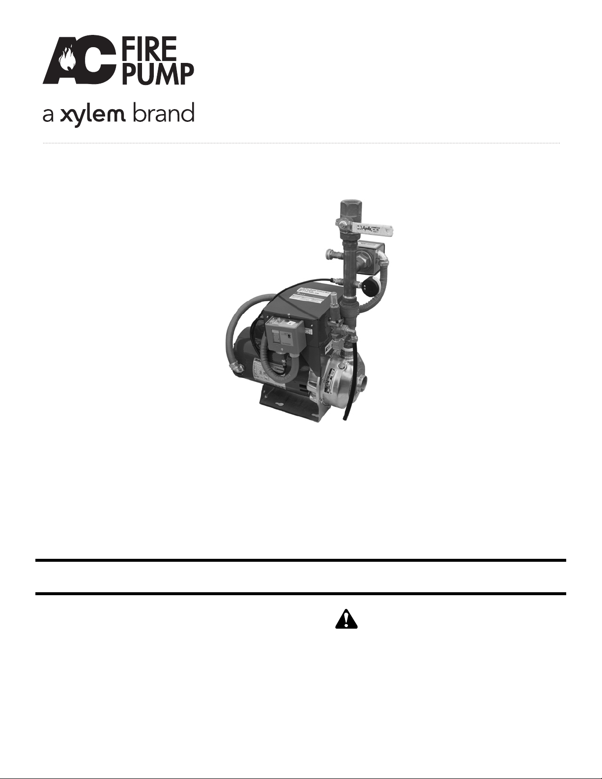
Residential Fire Pump Package
INSTALLER: PLEASE LEAVE THIS MANUAL FOR THE OWNER’S USE.
DESCRIPTION
The assembly consists of a single pump water boosting
system which increases riser pressure by as much as 55 PSI.
The pump is automatically controlled to run on demand. The
system is to be applied to NFPA 13D systems as required.
This safety alert symbol will be used in this manual and on the
Safety Instruction decal to draw attention to safety related
instructions. When used, the safety alert symbol means
ATTENTION! BECOME ALERT! YOUR SAFETY IS
INVOLVED! FAILURE TO FOLLOW THE INSTRUCTION
MAY RESULT IN A SAFETY HAZARD!
SAFETY
INSTRUCTIONS
Page 2

2
SECTION 1 - GENERAL DESCRIPTION Page
Purpose of Manual . . . . . . . . . . . . . . . . . . . . . . . . . . . . . . . . . . . . . . . . . . . . . . . . . . . . . . . . . . . . . . . . . . . 3
Safety Instructions . . . . . . . . . . . . . . . . . . . . . . . . . . . . . . . . . . . . . . . . . . . . . . . . . . . . . . . . . . . . . . . . . . . . 3
Storage and Handling . . . . . . . . . . . . . . . . . . . . . . . . . . . . . . . . . . . . . . . . . . . . . . . . . . . . . . . . . . . . . . . . . 3
Electrical Connections . . . . . . . . . . . . . . . . . . . . . . . . . . . . . . . . . . . . . . . . . . . . . . . . . . . . . . . . . . . . . . . . . 3
SECTION 2 - INSTALLATION . . . . . . . . . . . . . . . . . . . . . . . . . . . . . . . . . . . . . . . . . . . . . . . . . . . . . . . . . . 4
SECTION 3 - PUTTING THE UNIT INTO SERVICE . . . . . . . . . . . . . . . . . . . . . . . . . . . . . . . . . . . . . . . . . 5
Adjustments and Settings . . . . . . . . . . . . . . . . . . . . . . . . . . . . . . . . . . . . . . . . . . . . . . . . . . . . . . . . . . . . . . 5
SECTION 4 - FINAL CHECK LISTS . . . . . . . . . . . . . . . . . . . . . . . . . . . . . . . . . . . . . . . . . . . . . . . . . . . . . . 6
Start Up Check List – Piping . . . . . . . . . . . . . . . . . . . . . . . . . . . . . . . . . . . . . . . . . . . . . . . . . . . . . . . . . . . . 6
Start Up Check List – Electrical . . . . . . . . . . . . . . . . . . . . . . . . . . . . . . . . . . . . . . . . . . . . . . . . . . . . . . . . . . 6
SECTION 5 - TROUBLESHOOTING . . . . . . . . . . . . . . . . . . . . . . . . . . . . . . . . . . . . . . . . . . . . . . . . . . . . . 7
APPENDIX A - PROGRAMMABLE CONTROL MODULE . . . . . . . . . . . . . . . . . . . . . . . . . . . . . . . . . . . . 8
APPENDIX B - FIELD WIRING DIAGRAM . . . . . . . . . . . . . . . . . . . . . . . . . . . . . . . . . . . . . . . . . . . . . . . . 9
APPENDIX C - FIELD PIPING DIAGRAM . . . . . . . . . . . . . . . . . . . . . . . . . . . . . . . . . . . . . . . . . . . . . . . .10
Index
NOTE: The information contained in this manual is intended to assist operating personnel by providing information on the characteristics of the purchased equipment.
It does not relieve the user of the responsibility to adhere to local codes and ordinances and the use of accepted practices in
the installation, operation and maintenance of this equipment.
Further information pertaining to the installation, operation, and maintenance of your Residential Fire Pump Package can be
found in the installation Operation and Maintenance manuals for the associated equipment provided:
A. RCW NPE Pump (I.O.M. Part IMPROT)
B. Tank (Model Specific)
Page 3
1.1 The residential fire pumping package will increase the
domestic water pressure at the fixtures from 30 to 55
PSI above that of the city water pressure.
1.2 A pressure switch starts and stops the pump.
1.3
PURPOSE OF MANUAL
1.4 This manual is furnished to acquaint you with some
of the practical ways to install, operate, and maintain
this unit. Read it completely before doing any work
on your unit and keep it handy for future reference.
1.5 Equipment cannot operate well without proper care.
To keep this unit at top efficiency, follow the recommended installation and servicing procedure outlined
in this manual.
1.6
SAFETY INSTRUCTION
1.7 This safely alert symbol will be used in this manual
and on the unit safety instruction to draw attention to
safety related instructions. When used the safety alert
symbol means
ATTENTION BECOME ALERT!
YOUR SAFETY IS INVOLVED! FAILURE TO FOLLOW THIS INSTRUCTION MAY RESULT IN A
SAFETY HAZARD.
1.8 ADDITIONAL SAFETY REQUIREMENTS
1.9 Always use accurate test meters when checking electrical components. Always work with another person
in case of emergency.
1.10
STORAGE
1.11 For long periods of storage, the unit should be
covered to prevent corrosion and contamination from
dirt. It should be STORED in a clean, dry location
between 0 and 170°F. The relative humidity should
not exceed 85%. The unit should be checked periodically to ensure that no condensation has formed.
After storage, again check that it is dry before applying power.
1.12
HANDLING
1.13 Care should be taken to prevent damage due to
dropping or jolting when moving the Residential fire
pump package. Transportation damage should be
brought to the carrier's attention immediately upon
receipt.
1.13.1
Location
1.13.2 Install the residential fire pumping package appropriately for ease of inspection, maintenance and service.
Observe local electrical codes concerning control
panel spacing.
1.14 TEMPERATURE AND VENTILATION
1.15 All electrical equipment is susceptible to failure if
operated in ambient temperatures outside of its rating. The OPERATING temperature range for this unit
is 40 to 105°F. The relative humidity should not
exceed 85% non-condensing. The unit should not be
operated outside these extremes.
1.16
ELECTRICAL CONNECTIONS - A.C. POWER &
SIGNALS INPUT VOLTAGE
1.17 The input voltage tolerance is +10/-10% of nameplate voltage.
1.18
GROUND CONNECTIONS
1.19 A grounding terminal is provided for a dedicated
ground wire connection. All provisions of the National
Electrical Code and local codes must be followed.
1.20
POWER WIRING
1.21 Power wire types and sizes must be selected based
upon conformance with the National Electrical Code
and all local codes and restrictions. In addition, only
copper (Cu) wire rated for at least 75°C may be used
for the power connections. Refer to the input current
as listed on the motor nameplate when sizing wire.
Connect the input power to the screw terminals on
the motor contactor labeled "L1" & "L2". Connect a
ground conductor to the ground lug attached to the
circuit board.
1.21.1
System Pressure Switch
1.21.2 A system pressure switch is connected to the terminals labels "Pressure".
3
Section 1 - General Description
WARNING: Heavy load, may drop if not lifted properly.
Do not lift the entire unit by the motor eyebolts. Lift the
unit with slings placed under the unit base rails.
FAILURE
TO FOLLOW THESE INSTRUCTIONS COULD RESULT
IN SERIOUS PERSONAL INJURY, DEATH, AND/OR
PROPERTY DAMAGE.
WARNING: Electrical Shock Hazard. Inspect all
electrical connections prior to powering the unit.
Wiring connections must be made by a qualified electrician
in accordance with all applicable codes, ordinances, and
good practices.
FAILURE TO FOLLOW THESE INSTRUCTIONS COULD RESULT IN SERIOUS PERSONAL
INJURY, DEATH, AND/OR PROPERTY DAMAGE.
WARNING: Prevent electrical shocks. Disconnect
the power supply before beginning installation.
FAILURE TO FOLLOW THESE INSTRUCTIONS COULD
RESULT IN SERIOUS PERSONAL INJURY, DEATH,
AND/OR PROPERTY DAMAGE.
WARNING: Conduit grounds are not adequate. A
separate ground wire must be attached to the ground
lug provided in the enclosure to avoid potential safety hazards.
FAILURE TO FOLLOW THESE INSTRUCTIONS
COULD RESULT IN SERIOUS PERSONAL INJURY,
DEATH, AND/OR PROPERTY DAMAGE.
Page 4

4
1.21.3
Flow Switch
1.21.4 An optional flow switch is connected to the terminals
labels "Flow Sw".
1.21.5
Local or Remote Alarm Indication
1.21.6 Two relay outputs labeled "Out2" and "Out3" rated
for 7 Amps at 240VAC are supplied. These outputs
are normally open and close to indicate an alarm
condition exists. Out3 closes when the pressure
switch closes and stays closed until system pressure
restores and the preset timer expires. Out2 closes
when the flow switch closes and opens when the
flow switch opens.
1.22
FIELD CONNECTION DIAGRAMS
1.23 Refer to the RCW NPE pump Installation, Operation,
and Maintenance manual for specific details
unique to the pump.
1.24 The following field connection diagrams should be
reviewed prior to unit installation and operation.
Drawing # Description Page
Appendix B Field Wiring Diagram 9
Appendix C Field Piping Diagram 10
2.1 Place the unit preferably on a concrete floor or base.
Level the base in both directions by placing steel
shims between the base and the anchor bolts.
2.2 A well-leveled and secured unit will result in quiet
operation as well as longevity of service.
2.3 See drawing Appendix C for general piping requirements.
2.4 Eccentric increasers can be used in the suction line
when increasing the pipe size. The straight side of
eccentric reducers should be installed on top to eliminate air pockets. Support the suction and discharge
lines independently by the use of pipe hangers or
anchors. Do not attempt to spring the suction and
discharge lines into position.
2.5 The power supply required for the unit is indicted on
the nameplate located inside the control panel. A
dedicated ground wire must be connected to the unit.
Single phase motors have internal overload protection. The disconnecting means and short circuit protection are to be supplied and mounted by others.
2.6 For units installed with an optional tank, the tank
must be installed per the requirements of drawing
Appendix C. Fill the tank per the tank prior to putting
the unit into service.
WARNING: Heavy load, may drop if not lifted properly.
Do not lift the entire unit by the motor eyebolts. Lift
the unit with slings placed under the unit base rails.
FAILURE TO FOLLOW THESE INSTRUCTIONS COULD
RESULT IN SERIOUS PERSONAL INJURY, DEATH,
AND/OR PROPERTY DAMAGE.
CAUTION: The Residential fire pump package includes
a high pressure relief valve. Make sure the discharge
of the valve is directed to the floor drain before making the
unit operational.
FAILURE TO FOLLOW THESE INSTRUCTIONS COULD RESULT IN PROPERTY DAMAGE
AND/OR MODERATE PERSONAL INJURY.
Section 2 - Installation Instructions
WARNING: Electrical shock hazard. Inspect all elec-
trical connections prior to powering the unit. Wiring
connections must be made by a qualified electrician in
accordance with all applicable codes, ordinances, and
good practices.
FAILURE TO FOLLOW THESE INSTRUCTIONS COULD RESULT IN SERIOUS PERSONAL
INJURY, DEATH, AND/OR PROPERTY DAMAGE.
WARNING: Conduit grounds are not adequate. A
separate ground wire must be attached to the ground
lug provided in the enclosure to avoid potential safety hazards.
FAILURE TO FOLLOW THESE INSTRUCTIONS
COULD RESULT IN SERIOUS PERSONAL INJURY,
DEATH, AND/OR PROPERTY DAMAGE.
CAUTION: Seal damage may occur. Do not run
pumps dry. Fill and vent the pump volute prior to
operation.
FAILURE TO FOLLOW THESE INSTRUCTIONS
COULD RESULT IN PROPERTY DAMAGE AND/OR
MODERATE PERSONAL INJURY.
Page 5

5
3.1 Whenever the riser water pressure falls below the
system pressure switch setting the pump will start
through a power relay.
3.2 When the system pressure rises above the setting of
the system pressure switch the pump will stop (provided the minimum run timer has expired.)
3.3
ADJUSTMENTS AND SETTINGS
3.3.1 System Pressure Switch
3.3.2 Back out the locking screw (see Figure 1) to allow
main adjustment wheel to turn freely.
a) Determine the pressure to be maintained across
the sprinkler system.
b) Adjust main adjustment wheel (see Figure 1) to de-
sired setting for pump to turn ON.
c) Turn main adjustment wheel counterclockwise to
increase or clockwise to decrease pressure. Each
number on main adjust wheel represents an approximate window shift of 1.8 psi for EPS40-2. For
each 1/2 rotation of the adjustment wheel the window changes by approximately 11 psi for EPS40-2.
The LED on Out3 will come ON in the control panel
when pressure switch is activated.
d) The pressure switch has a fixed differential which
doesn't require adjustment for turning OFF the
pump. The approximate differential varies from 3
psi @ 10 psi system pressure to 6 psi @ 100 psi
system pressure.
e) Retest the set point several times to ensure the
accuracy of the setting and to ensure the pump
starts and stops at the correct pressure.
f) Re-seat locking screw.
3.3.6 The minimum run timer is factory set to 5 minutes.
The setting should be verified before the unit is placed
into operation and adjusted if a shorter minimum run
time is desired. Do not adjust the timer with power
applied to the unit. Set the run timer by moving the
small black plastic jumper on the right side of the
PCB to 15 seconds, 30 seconds, 1 min, 2 min, 3 min,
4 min, or 5 min. The system will default to 15 seconds if no jumper is used.
3.3.7
Optional Tank
3.3.8 Refer to the specific IOM that was shipped with the
tank for installation and operating instructions.
3.3.9 Procedure to set Relief valve:
a) Switch ON the pump by opening the test valve
slowly to create a pressure drop.
b) Close the test valve after the pump turns ON.
c) Let the pump run until it reaches the set pressure
and switches OFF.
d) Loosen (counterclockwise) adjusting screw in
relief valve until it releases pressure.
Section 3 - Putting the Unit Into Service
CAUTION: Prevent subsequent damage. A unit
showing symptoms of possible problems (noise,
leaks, vibration, and/or continual operation) must be corrected immediately.
FAILURE TO FOLLOW THESE
INSTRUCTIONS COULD RESULT IN PROPERTY DAMAGE AND/OR MODERATE PERSONAL INJURY.
CAUTION: Relief valve exhaust must be piped to
an adequately sized drain.
FAILURE TO FOLLOW
THESE INSTRUCTIONS COULD RESULT IN PROPERTY
DAMAGE AND/OR MODERATE PERSONAL INJURY.
WARNING: Electrical shock hazard. Disconnect and
lockout power before servicing the unit.
FAILURE TO
FOLLOW THESE INSTRUCTIONS COULD RESULT IN
SERIOUS PERSONAL INJURY, DEATH, AND/OR PROPERTY DAMAGE.
WARNING: Electrical shock hazard. Disconnect and
lockout power before servicing the unit.
FAILURE TO
FOLLOW THESE INSTRUCTIONS COULD RESULT IN
SERIOUS PERSONAL INJURY, DEATH, AND/OR PROPERTY DAMAGE.
FIGURE 1
Page 6

6
A. SYSTEM PIPING AND UNIT
INSTALLATION
____ 1. Is the unit base properly leveled and secured?
____ 2. Is the shut-off valves to the pump suction open?
____ 3. Is the shut-off valve on the discharge line open?
____ 4. Is the shut-off valve on the hose bib closed?
____ 5. Is the piping properly supported to prevent strains
on unit?
____ 6. Is the system, including the pumps, purged of debris
and air?
B. ELECTRICAL WIRING AND
CONTROL SETTINGS
____ 1. Does the feeder line voltage correspond to the unit
voltage? Check the unit nameplate or motor terminal
connection.
____ 2. Are the feeder wires correctly sized for the load?
____ 3. Have all the power terminals in the control panel
been checked for tightness? This is imperative since
stranded wires tend to “flow” and become loose
after initial installation.
____ 4. Is the pressure control correctly set? The pressure
switch needs to be set for proper operation. For
best results, use a continuity meter (across the
switch) to reset the controls. The legend plate on
the control indicates approximate readings only and
therefore should be used with caution.
WARNING: Electrical shock hazard. Inspect all elec-
trical connections prior to powering the unit. Wiring
connections must be made by a qualified electrician in
accordance with all applicable codes, ordinances, and
good practices.
FAILURE TO FOLLOW THESE INSTRUCTIONS COULD RESULT IN SERIOUS PERSONAL
INJURY, DEATH, AND/OR PROPERTY DAMAGE.
WARNING: Electrical shock hazard. Single phase
AC power. Disconnect and lockout power before
servicing the unit.
FAILURE TO FOLLOW THESE
INSTRUCTIONS COULD RESULT IN SERIOUS PERSONAL INJURY, DEATH, AND/OR PROPERTY
DAMAGE.
WARNING: Conduit grounds are not adequate. A
separate ground wire must be attached to the
ground lug provided in the enclosure to avoid potential
safety hazards.
FAILURE TO FOLLOW THESE INSTRUCTIONS COULD RESULT IN SERIOUS PERSONAL
INJURY, DEATH, AND/OR PROPERTY DAMAGE.
CAUTION: Seal damage may occur. Do not run
pumps dry. Fill and vent the pump volute prior to
operation.
FAILURE TO FOLLOW THESE INSTRUCTIONS COULD RESULT IN PROPERTY DAMAGE
AND/OR MODERATE PERSONAL INJURY.
Section 4 - Final Check List
Page 7

5.1 Pump will not operate
1) Check incoming power
2) Check motor overload. Reset if tripped.
3) With contactor pulled in, check voltage of the
motor leads. Voltage should be the same as the
incoming power. If no voltage is present, replace the
contactor. If voltage is present, contact an electrician
to check the leads and motor.
5.2
Pump will not build pressure
1) Suction valve is closed. If closed, open.
2) Discharge valve is closed. If closed, open.
3) Relief valve is open and discharging to drain, Reset
relief valve to correct pressure setting.
4) Hose bib is open. If open, close.
5) Motor not operating at rated RPM. Have motor
checked at local motor repair shop.
6) Internal pump damage. Take pump to authorized
pump repair facility.
5.3
Pump will not start automatically
1) No power. Restore if there is no power.
2) System pressure switch is not adjusted properly.
Refer to section 3.
7
Section 5 - Troubleshooting
DANGER: Troubleshooting live control panels ex-
poses personnel to hazardous voltages. Electrical
troubleshooting must only be done by a qualified electrician.
FAILURE TO FOLLOW THESE INSTRUCTIONS
COULD RESULT IN SERIOUS PERSONAL INJURY,
DEATH, AND/OR PROPERTY DAMAGE.
WARNING: Electrical shock hazard. Inspect all elec-
trical connections prior to powering the unit. Wiring
connections must be made by a qualified electrician in
accordance with all applicable codes, ordinances, and
good practices.
FAILURE TO FOLLOW THESE INSTRUCTIONS COULD RESULT IN SERIOUS PERSONAL
INJURY, DEATH, AND/OR PROPERTY DAMAGE.
Page 8

8
1.1 The control system allows for intelligent pump control
while improving system reliability. Timers and relays
used in a conventional controller are integrated into a
single sequence controller. The working program is
stored on a non-volatile EEPROM chip that is an integral part of the unit. This means there is no danger of
ever losing a program due to power losses.
1.2. OK LED is on when the processor is running. If this
LED is not lit, check power connections. If power is
applied to the unit and LED is still not lit, replace unit.
1.3. The Aux in LED is reserved for future use.
1.4. The Flow Sw. LED is lit when the flow switch is
closed.
1.5. The Pressure LED is lit when the pressure switch is
closed.
1.6. The Out3 LED is lit when Output 3 is closed. Output
3 is closed when the pressure switch is closed, or
when the pressure switch is open and the run timer is
active.
1.7. The Out2 LED is lit when Output 2 is closed. Output
2 is closed when the flow switch is closed.
1.8. The Contactor LED is lit when the Contactor output is
closed. The Contactor output closes when the pressure switch is closed, or when the pressure switch is
open and the run timer is active.
2.0 CHANGING THE MINIMUM RUN TIME
2.1 Adjustable Settings
2.2 The run timer is adjustable to 15 seconds, 30 seconds, 1 minute, 2 minutes, 3 minutes, 4 minutes, and
5 minutes. On the right hand side of the PCB near
the OK LED is a small black plastic jumper which sets
the run time. Shorting the pins at the top of the connector will set the run time to 5 minutes. Shorting the
next set of pins down will set the timer to 4 minutes.
Shorting the bottom set of pins sets the timer to 15
seconds. Each setting is labeled on the PCB. If no
jumper is used, the timer defaults to 15 seconds.
Appendix A - Programmable Control Module
WARNING: Electrical shock hazard. Inspect all elec-
trical connections prior to powering the unit. Wiring
connections must be made by a qualified electrician in
accordance with all applicable codes, ordinances, and
good practices.
FAILURE TO FOLLOW THESE INSTRUCTIONS COULD RESULT IN SERIOUS PERSONAL
INJURY, DEATH, AND/OR PROPERTY DAMAGE.
WARNING: Electrical shock hazard. Disconnect and
lockout power before servicing the unit.
FAILURE
TO FOLLOW THESE INSTRUCTIONS COULD RESULT
IN SERIOUS PERSONAL INJURY, DEATH, AND/OR
PROPERTY DAMAGE.
Page 9

9
Appendix B - Field Wiring Diagram
Voltage HP Amps M1-M2 GND Conduit Size
230 1-1/2 10 #14 #12 1/2"
230 3 17 #10 #10 1/2"
230 5 28 #8 #8 1/2"
Page 10

Appendix C - Field Piping Diagram
Xylem Inc.
10661 Newkirk Street
Dallas, TX 75220
Phone: (469) 221-1200
Fax: (214) 357-5861
www.xyleminc.com/brands/acfirepump
A-C Fire Pump is a trademark of Xylem Inc. or one of its subsidiaries.
© 2012 Xylem Inc. 19-001-290B August 2012
 Loading...