

Page 1
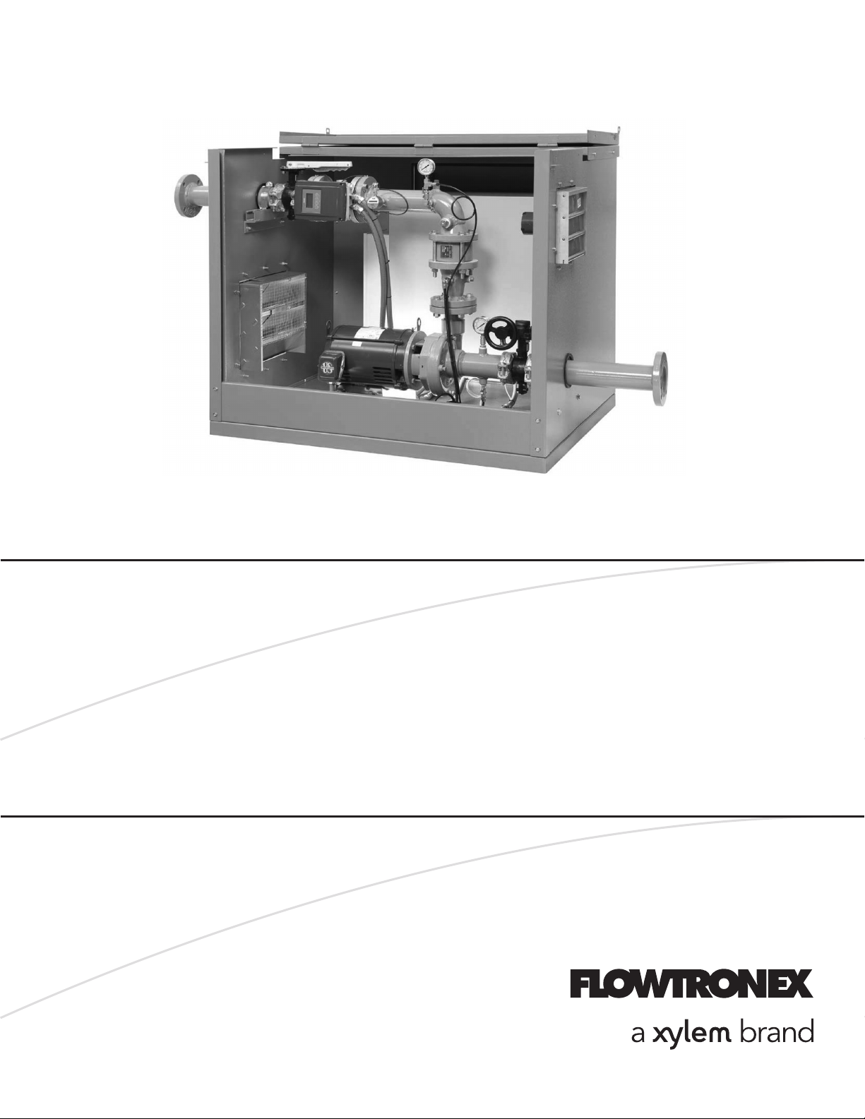
INSTRUCTION MANUAL
19-001-251R3
INSTALLER: PLEASE LEAVE THIS MANUAL FOR THE OWNER’S USE.
Floboy
™
VFD Pumping System
NOTE: This product is not intended for use in potable water applications.
Page 2

Acknowledgements
All materials ©2013 by Flowtronex®, an Xylem company.
Flowtronex® is a registered trademark of Xylem Flowtronex.
All rights reserved. No parts of this work may be reproduced in any form or by any means - graphic,
electronic, or mechanical, including photocopying, recording, taping, or information storage and retrieval
systems - without the written permission of the publisher.
Products that are referred to in this document may be either trademarks and/or registered trademarks of
the respective owners. The publisher and the author make no claim to these trademarks. These include
Microsoft, Windows, Windows NT, ActiveX that are either registered trademarks or trademarks of Microsoft
Corporation in the United States and/or other countries. ©2013 Microsoft Corporation. All rights reserved.
WHILE EVERY PRECAUTION HAS BEEN TAKEN IN THE PREPARATION OF THIS DOCUMENT, THE
PUBLISHER AND THE AUTHOR ASSUME NO RESPONSIBILITY FOR ERRORS OR OMISSIONS, OR
FOR DAMAGES RESULTING FROM THE USE OF INFORMATION CONTAINED IN THIS DOCUMENT
OR FROM THE USE OF PROGRAMS AND SOURCE CODE THAT MAY ACCOMPANY IT. IN NO EVENT
SHALL THE PUBLISHER AND THE AUTHOR BE LIABLE FOR ANY LOSS OF PROFIT OR ANY OTHER
COMMERCIAL DAMAGE CAUSED OR ALLEGED TO HAVE BEEN CAUSED DIRECTLY OR
INDIRECTLY BY THIS DOCUMENT.
Page 3

TABLE OF CONTENTS
ACKNOWLEDGEMENTS II
TABLE OF CONTENTS ·········································· I
TABLE OF FIGURES ············································· II
WARRANTY INFORMATION ··································· 2
SAFETY ······························································· 3
Safety instructions .................................................... 3
Safety Reminders ..................................................... 3
Additional Safety Information ................................... 4
Safety Apparel .......................................................... 4
Coupling Guards ...................................................... 4
Operation .................................................................. 4
Maintenance Safety .................................................. 4
GENERAL DESCRIPTION ······································ 5
Product Description .................................................. 5
Operational Limits .................................................... 5
Nameplate Information ............................................. 5
Station Numbering: ................................................... 6
Example: FBSNV4BF10D46R3ABD ........................ 6
handling .................................................................... 7
Storage ..................................................................... 7
Field Connection Diagrams ...................................... 7
Ground Connections ................................................ 7
RECEIVING ·························································· 8
Preparing to Receive the Pump Station ................... 8
Inspecting the Shipment ........................................... 8
Unpacking and Storing This Equipment ................... 8
INSTALLATION ···················································· 8
Location .................................................................... 8
Foundation ............................................................... 9
Anchoring the Station ............................................... 9
Suction Piping .......................................................... 9
Discharge Piping .................................................... 12
Electrical Connections ............................................ 12
START-UP AND ADJUSTMENTS ···························· 13
Power Check .......................................................... 13
Voltage Variance .................................................... 13
Voltage Imbalance .................................................. 13
Pump Priming ......................................................... 13
Pump Rotation ........................................................ 14
System Pressurization ............................................ 15
Priming Line Adjustment ........................................ 15
Overload Trip Adjustment ....................................... 15
STATION OPERATION ·········································· 16
DOOR SWITCH OPERATION ............................... 16
Individual Pump Switches .............................. 16
OPERATIONAL SETTINGS IN THE HMI .............. 16
Auto-Manual Select ........................................ 16
LDP Override ................................................. 16
Reset Control (F5) .......................................... 16
Resetting Faults ............................................. 16
AUTOMATIC OPERATION .................................... 17
Overview ........................................................ 17
System Charging Mode .................................. 17
NORMAL OPERATION .......................................... 17
MANUAL VFD OPERATION .................................. 18
CONTROLLER BYPASS OPERATION ................. 19
Overview ........................................................ 19
SYSTEM SAFETIES .............................................. 19
Fault Reset ..................................................... 19
Low Discharge Pressure ................................ 19
High Discharge Pressure ............................... 19
Low Inlet Pressure ......................................... 20
Loss of Prime ................................................. 20
INDIVIDUAL PUMP FAULTS ......................... 21
Overload Protection ....................................... 21
High Pump Temperature (Optional) ............... 21
VFD Fault ....................................................... 21
NAVIGATING THE CONTROLS ······························· 21
Overview ................................................................ 21
Pump Status Indicators .......................................... 22
Pressure Setpoint Adjustment ................................ 22
Trends and Alarms ................................................. 23
Totals ..................................................................... 24
Pump Control ......................................................... 24
Start settings .......................................................... 24
Stop Settings .......................................................... 24
Speed Test ............................................................. 25
Safety ..................................................................... 25
Panel Config ........................................................... 25
Sys Config .............................................................. 25
PID Parameters ...................................................... 25
Other Settings ........................................................ 25
MAINTENANCE ···················································· 26
REGULAR MONTHLY MAINTENANCE INTERVALS
............................................................................... 26
Heat exchanger: ............................................. 26
Control panel: ................................................. 26
Motor lubrication: ............................................ 26
Pumps - horizontal: ........................................ 26
Sound and visual checks of whole station: .... 26
Station skid: .................................................... 26
WINTERIZING the PUMP STATION ..................... 27
Winterizing ..................................................... 27
Spring Restart ................................................ 27
TROUBLESHOOTING ············································ 28
LOW DISCHARGE PRESSURE FAULT ............... 28
HIGH DISCHARGE PRESSURE FAULT ............... 29
LOW LEVEL FAULT .............................................. 29
LOW INLET PRESSURE FAULT ........................... 29
LOSS OF PRIME FAULT ....................................... 30
VFD FAULT ............................................................ 30
MOTOR WON’T START ........................................ 31
GLOSSARY OF TERMS ········································· 32
APPENDIX A — FINAL CHECK LIST ························ 35
APPENDIX B — ELECTRICAL WIRING AND
CONTROL SETTINGS FINAL CHECKLIST ················ 36
Page 4

TABLE OF FIGURES
Figure 1: Typical Floboy suction and discharge piping, Boost applications ....................................................... 5
Figure 2: Typical Floboy suction and discharge piping, Lift applications ........................................................... 5
Figure 3: Sample Nameplate ............................................................................................................................. 6
Figure 4: Typical Floboy installation on slab. ..................................................................................................... 9
Figure 5: Anchoring the station to the concrete slab. ......................................................................................... 9
Figure 6: Proper suction lift principles .............................................................................................................. 11
Figure 7: Improper suction lift application ........................................................................................................ 11
Figure 8: Proper installation of pump ............................................................................................................... 12
Figure 9: Confirm rotation by making sure motor is operating in the direction of the motor tag ...................... 15
Figure 10: Floboy controller. ............................................................................................................................ 22
Figure 11: Main Screen .................................................................................................................................... 22
Figure 12: Pump Status Indicators ................................................................................................................... 22
Figure 13: Perssure Setpoint ........................................................................................................................... 22
Figure 14: Setpoint Password Entry Screen .................................................................................................... 22
Figure 15: Entering the password for the setpoint screen ............................................................................... 23
Figure 16: Changing the setpoint ..................................................................................................................... 23
Figure 17: Performance Graph ........................................................................................................................ 23
Figure 18: Alarms Screen ................................................................................................................................ 23
Figure 19: Alarm Description ........................................................................................................................... 23
Figure 20: Menu ............................................................................................................................................... 24
Figure 21: Totals .............................................................................................................................................. 24
Figure 22: Pump Control .................................................................................................................................. 24
Figure 23: Stop Settings .................................................................................................................................. 24
Figure 24: Pump Control, Combo Selection .................................................................................................... 24
Figure 25: Speed Test ..................................................................................................................................... 25
Figure 26: Safety .............................................................................................................................................. 25
Figure 27: Safety, Others ................................................................................................................................. 25
Figure 28: Panel Configuration ........................................................................................................................ 25
Page 5

NOTE: The information contained in this book is intended to assist operating personnel by providing
information about the characteristics of the purchased equipment.
It does not relieve the user of their responsibility of using accepted engineering practices in the installation,
operation, and maintenance of this equipment.
For additional questions, contact:
XYLEM FLOWTRONEX
8:00 AM to 5:00 PM Central time (800) 786-7480 x3
5:00 PM to 8:00 AM Central time
After Hours technician for emergency assistance: (214) 454-5768
support@flowtronex.com
Page 6

2
WARRANTY INFORMATION
Company warrants title to the product(s) and,
except as noted below with respect to items not of
Company’s Manufacturer, also warrants the
product(s) on date on shipment to Purchaser, to
be of the kind and quality described herein, and
free of defects in workmanship and material.
THIS WARRANTY IS EXPRESSLY IN LIEU OF
ALL OTHER WARRANTIES, INCLUDING BUT
NOT LIMITED TO IMPLIED WARRANTIES OF
MECHANTABILITY AND FITNESS, AND
CONSTITUTES THE ONLY WARRANTY OF
COMPANY WITH RESPECT TO THE
PRODUCT(S).
If within one year from date of initial operation, but
nor more than eighteen months from date of
shipment by Company of any item of product(s),
Purchaser discovers that such item was not as
warranted above and promptly notifies Company
in writing thereof, Company shall remedy such
non-conformance by, at Company affected part of
the product(s). Purchaser shall assume all
responsibility and expense for removal,
reinstallation, and freight in connection with the
foregoing remedies. The same obligations and
conditions shall extend to replacement parts
furnished by Company hereunder. Company shall
have the right of disposal of parts replaced by it.
ANY SEPARATELY LISTED ITEM OF THE
PRODUCT(S) WHICH IS NOT MANUFACTURED
BY THE COMPANY IS NOT WARRANTED BY
COMPANY and shall be covered only the express
warrant, if any, of the manufacturer thereof.
THIS STATES PURCHASER’S EXCLUSIVE
REMEDY AGAINST COMPANY AND ITS
SUPPLIERS RELATING TO THE PRODUCT(S),
WHETHER IN CONTRACT OR IN TORT OR
UNDER ANY OTHER LEGAL THEORY, AND
WHETHER ARISING OUT OF WARRANTIES,
REPRESENTATIONS, INSTRUCTIONS,
INSTALLATIONS OR DEFECTS FROM ANY
CAUSE. Company and its suppliers shall have no
obligation as to any product which has been
improperly stored and handled, or which has not
been operated or maintained according to
instructions in Company or supplier furnished
manuals.
Page 7
3
SAFETY
Read all safety information prior to installation
of your pumping system.
SAFETY INSTRUCTIONS
SAFETY INSTRUCTION
This is a SAFETY ALERT SYMBOL. It is used
to alert you to potential personal injury
hazards. Obey all safety messages that follow
this symbol to avoid possible injury or death!
FAILURE TO FOLLOW THE INSTRUCTIONS
MAY RESULT IN A SAFETY HAZARD.
DANGER
Indicates a potentially hazardous situation
which, if not avoided, will result in death or
serious injury.
WARNING
Indicates a potentially hazardous situation
which, if not avoided, could result in death or
serious injury.
CAUTION
Indicates a potentially hazardous situation,
which if not avoided, may result in minor or
moderate injury.
CAUTION
Used without the safety alert symbol indicates
a potentially hazardous situation, which, if not
avoided, may result in property damage.
All operating instructions must be
read, understood, and followed by
the operating personnel.
Flowtronex accepts no liability for
damages or operating disorder
which are the result of non
compliance with the operating
instructions.
When the Pumping System
components reach the end of life
the components should be
disposed of or recycled in
accordance with local laws.
SAFETY REMINDERS
1. This manual is intended to assist in
the installation, operation, and repair
of the system and must be kept with
the system.
2. Installation and maintenance MUST
be performed by properly trained and
qualified personnel.
3. Review all instructions and warnings
prior to performing any work on the
system.
4. Any safety decals MUST be left on
the controller and pump.
5. The system MUST be disconnected
from the main power supply before
attempting any operation or
maintenance on the electrical or
mechanical part of the system.
Failure to disconnect electrical power
before attempting any operation or
maintenance can result in electrical
shock, burns, or death.
Page 8

4
ADDITIONAL SAFETY INFORMATION
This pump has been designed for safe and reliable
operation. A pump is a pressure-containing device
with rotating parts that could be hazardous.
Operators and maintenance personnel must
realize this and follow necessary safety measures.
Proper safety procedures must be followed. Xylem
Flowtronex shall not be liable for damage or
delays caused by a failure to observe the
instructions in this manual.
SAFETY APPAREL:
• Wear insulated work gloves when
handling hot bearings or using bearing
heater.
• Wear heavy work gloves when handling
parts with sharp edges, especially
impellers.
• Wear safety glasses (with side shields) for
eye protection, especially in machine shop
areas.
• Wear steel-toed shoes for foot protection
when handling parts, heavy tools, etc.
• Wear other personal protective equipment
to protect against hazardous/toxic fluids.
COUPLING GUARDS:
• Never operate a pump without a coupling
guard properly installed.
• Never force piping to make a connection
with a pump.
• Use only fasteners of the proper size and
material.
• Ensure there are no missing fasteners.
• Beware of corroded or loose fasteners.
OPERATION:
• Do not operate below minimum rated flow,
or with suction/discharge valves closed.
• Do not open vent or drain valves, or
remove plugs while system is pressurized.
MAINTENANCE SAFETY:
• Always lock out power.
• Ensure power is isolated from system and
pressure is relieved before disassembling
pump, removing plugs, or disconnecting
piping.
• Use proper lifting and supporting
equipment to prevent serious injury.
• Observe proper decontamination
procedures.
• Know and follow company safety
regulations.
• Never apply heat to remove impeller.
• Observe all cautions and warnings
highlighted in pump instruction manual.
Page 9
GENERAL DESCRIPTION
PRODUCT DESCRIPTION
Floboy Pumping Systems are self-contained,
pre-assembled and factory-tested pumping
systems. Floboy utilizes state of the art
technology, yet employs a simplistic and straight
forward design that makes installation, operation
and maintenance an easy task, even for the
most inexperienced of operators.
This manual will serve as a guide to
understanding the features of Floboy Pumping
Systems and provide a quick and clear
reference for answers to most questions
pertaining to its service. Every attempt has been
made to explain all facets of system operation
and maintenance for a variety of applications.
However, should you have specific questions
not explained or illustrated in this manual you
are encouraged to contact your nearest Floboy
Pumping Systems distributor, representative or
the factory.
Floboy utilizes a single main pump (with or
without a pressure maintenance pump) to supply
water to a turf irrigation system or other nonpotable application requiring water at a constant
pressure. Because Floboy is a totally automatic
system, the pump is energized whenever a
demand for water is sensed (pressure start).
Conversely, the pump is de-energized when the
demand no longer exists (pressure stop or flow
stop). In this manner, pressure is maintained in
any system at all times, thereby reducing piping
fatigue and minimizing the introduction of air into
the piping network.
For those customers who wish to start and stop
a pump based on a remote signal, as with an
irrigation controller, this function is available as a
selectable option on all models of Floboy. The
system can be controlled using 24V AC/DC
signal outputs from an irrigation controller or
other control devices (relay start).
Figure 1: Typical Floboy suction and discharge
piping, Boost applications
Figure 2: Typical Floboy suction and discharge
piping, Lift applications
OPERATIONAL LIMITS
See pumping system nameplate information for
pumping system flow capacity, pressure, full
load current and electrical ratings.
Unless special provisions have been made for
your pumping systems, the system pressure
rating is 175 psi for end suction centrifugal.
NAMEPLATE INFORMATION
The system nameplate gives identification and
rating information as shown below.
Page 10

6
Figure 3: Sample Nameplate
Field
Explanation
Voltage
Required input voltage
SCCR
Short circuit current rating
Phase
Number of motor phases
FLA
Full load amps
Hz
Required frequency (hertz)
Max. HP
Maximum horsepower
Permanent records for this system are
referenced by the serial number. Include the
serial number with all correspondence and spare
parts orders.
STATION NUMBERING:
EXAMPLE: FBSNV4BF10D46R3ABD
08FB=Floboy II
1. Size Code
a. S=Small (52”l x 40”w x 45”h)
b. M=Mid (64”l x 53” w x 55” h’)
2. Lift or Boost
3. Control Type: V = VFD
4. Pump model
5. Horsepower
6. Impeller Code. Specific to type of pump
used.
7. Voltage (46=460, 23=230, 20=208)
8. Start/Stop Control. R=Relay, F=Flow,
P=Pressure. Floboy 2009 models are
field configurable between models,
unlike the previous Floboy systems.
9. Phase: 3=3 Phase, 1=single phase. 3Phase power is generally more efficient
and less expensive per KWH, but may
not be available.
Page 11
7
HANDLING
Qualified personnel should unload and handle
the unit. Prevent damage due to dropping or
jolting when moving the unit. Thoroughly inspect
the unit for damage upon receipt. Immediately
notify the carrier of transportation damage.
Ensure that sensing lines are free of crimps and
kinks.
The unit is top heavy due to the position of the
equipment. Do not use component eyebolts to
lift the pump station.
WARNING: Falling Objects Hazard
Eyebolts, if provided, are designed to lift only
the components to which they are attached.
Failure to follow these instructions could result
in serious personal injury, death, and/or
property damage.
STORAGE
During periods of storage, the unit should be
covered to prevent corrosion and contamination
from dirt. Store the unit in a clean, dry location to
prevent condensation and freezing. After
storage, check that it is dry before applying
power. Specific component storage instructions
must be followed in accordance with the
respective equipment manufacturer's
recommendations.
CAUTION: Extreme Temperature Hazard
Extreme temperatures are to be avoided.
(Below 32ºF and above 110ºF.)
Failure to follow these instructions could result
in serious property damage and/or moderate
personal injury.
FIELD CONNECTION DIAGRAMS
Actual equipment manufacturers/models
installed are system specific. Refer to specific
manufacturers’ Installation, Operation &
Maintenance Manuals for details unique to each
component. The pump instruction manual is
supplied with the system (if applicable).
Review the wiring diagrams and dimensional
drawings prior to unit installation and operation.
Typical wiring diagrams are included in
Appendix D.
NOTE: Electrical supply must match the control
panel nameplate specification. Incorrect voltage
can cause fire, damaging electrical components
and void the warranty.
NOTE: Electrical supply must be installed by a
qualified electrician in accordance with all
applicable codes, ordinances, and good
practice.
GROUND CONNECTIONS
A grounding terminal is provided for a dedicated
ground wire connection. All provisions of the
National Electrical Code and local codes must
be followed.
WARNING: Electrical Shock Hazard
Conduit grounds are not adequate. A separate
ground wire must be attached to the ground lug
provided in the enclosure to avoid potential
safety hazards.
Failure to follow these instructions could result
in serious personal injury or death, or property
damage.
Page 12
8
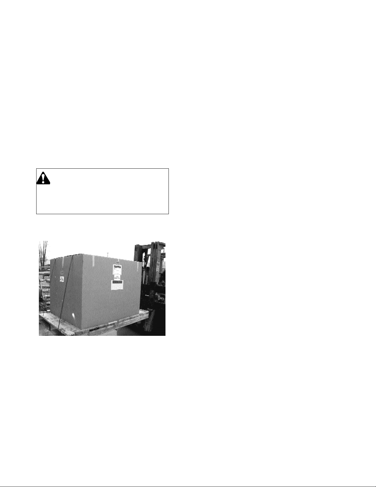
RECEIVING
PREPARING TO RECEIVE THE PUMP STATION
Each Floboy Pumping System is shipped on a
wooden pallet and is enclosed in either a
cardboard box or shrink wrap. It will probably
arrive in an enclosed van or semi-trailer which will
require specialized equipment, such as a fork lift,
to off-load. Please remember, it is your
responsibility to provide a safe and secure means
to remove this equipment from the carrier's
vehicle. Once you take possession of the pump
station, the freight carrier is no longer responsible
for damage due to mishandling.
CAUTION
Caution: This equipment is heavy. Do not
attempt to pick it up or move it manually.
Bodily injury may result.
INSPECTING THE SHIPMENT
Inspect the pump station for damaged goods
prior to accepting shipment. Note all damages or
missing components on the "Bill of Lading".
Note: When the pump station arrives, it is your
responsibility to inspect this equipment for
damage or lost goods prior to signing the
carrier's freight bill.
Should you notice shorted or damaged goods, you
must make a notation to that effect on the face of
the "freight bill" and keep a copy so a claim can be
processed with the freight company. If you give
the freight company a clear receipt for goods that
have been damaged or lost in transit you do so at
your own risk and expense.
If you receive the pump station and subsequently
discover damaged equipment or lost goods that
were concealed by the packaging you must
contact the freight company immediately. Do not
proceed with the system's installation until the
freight company has inspected this equipment. A
"Concealed Damage Report" must be made within
15 days of receiving the equipment or any claim of
loss will not be honored.
The factory will assist you in every possible
manner to collect a claim for loss or damage but
be advised that the laws of interstate commerce
make it your responsibility to file, process and
collect all claims directly from the freight company
or its agent.
UNPACKING AND STORING THIS EQUIPMENT
When cutting the packaging with a knife or razor,
take care not to scratch the paint on the metal
enclosure. If the pump station is to be stored for
any period of time, make certain it is left in a
secure location, preferably one which is free of
excessive moisture and freezing conditions.
INSTALLATION
LOCATION
Locate the pumping system in a clean, well
ventilated, and properly drained location. It is
recommended that the location selected facilitates
ease of inspection, maintenance, and service.
Outside installation requires protection from
freezing.
The factory recommends positioning the Floboy
Pumping System on a concrete slab that provides
a permanent and supportive base. The system
should be positioned as close to the intended
source of water as possible. For systems lifting
water from a lake or pond, the pump station
elevation should be close to the water surface
elevation. In most cases the pump site should
never be more than five feet above the minimum
water elevation as long as this elevation is above
the normal flood plane.
Page 13

9
Concrete slabs should be at least 6" thick and be
constructed in a monolithic pour from 3000 psi
concrete and #5 rebar. The slab should be sized
with a minimum of 6" clearance between the edge
of the slab and the edge of the pump station.
Please note that it is the customer's
responsibility to meet all local code and
seismic requirements.
WARNING: Falling Objects Hazard Heavy Load, May Drop If Not Lifted
Properly.
Do not lift the entire unit by component eyebolts.
Eyebolts on components are used for factory
assembly only and are not intended to lift the
complete package.
Failure to follow these instructions could result in
serious personal injury or death, or property
damage.
FOUNDATION
With proper installation and a suitable foundation,
this unit is built to supply years of service.
Establish a base of concrete weighing a minimum
of 2-1/2 times the weight of the unit. (Check the
shipping tickets or the pumping system drawing for
unit weight.) Tie the concrete pad in with the
finished floor. Use the appropriate anchor bolts to
secure the pumping system to the foundation.
Pump packages with electrical conduit below
surface may require corrosion protection approved
for this condition.
WARNING: Electrical Shock Hazard
Electrical conduit installed below the surface may
require a corrosion resistant protective coating to
prevent conduit corrosion and electrical shock.
Failure to follow these instructions could result in
serious personal injury or death, or property
damage.
Place the unit on its concrete foundation,
supporting it with steel wedges or shims. These
wedges or shims should be put on both sides of
each anchor-bolt and midway between the bolts,
to provide a means of leveling the base.
After the pumping system has been leveled, install
the correct number of anchor bolts and tighten to
secure the system.
Figure 4: Typical Floboy installation on slab.
ANCHORING THE STATION
It is always advisable to anchor the station to the
concrete slab or support structure in two or more
locations. Four 1/2" diameter holes have been
provided in the base of the pump station skid for
this purpose. Concrete anchors, such as 3/8" x 4"
Redheads, work well on most concrete structures.
Anchor all four holes. Please note that it's the
customer responsibility to meet any seismic
requirements if applicable.
Figure 5: Anchoring the station to the concrete
slab.
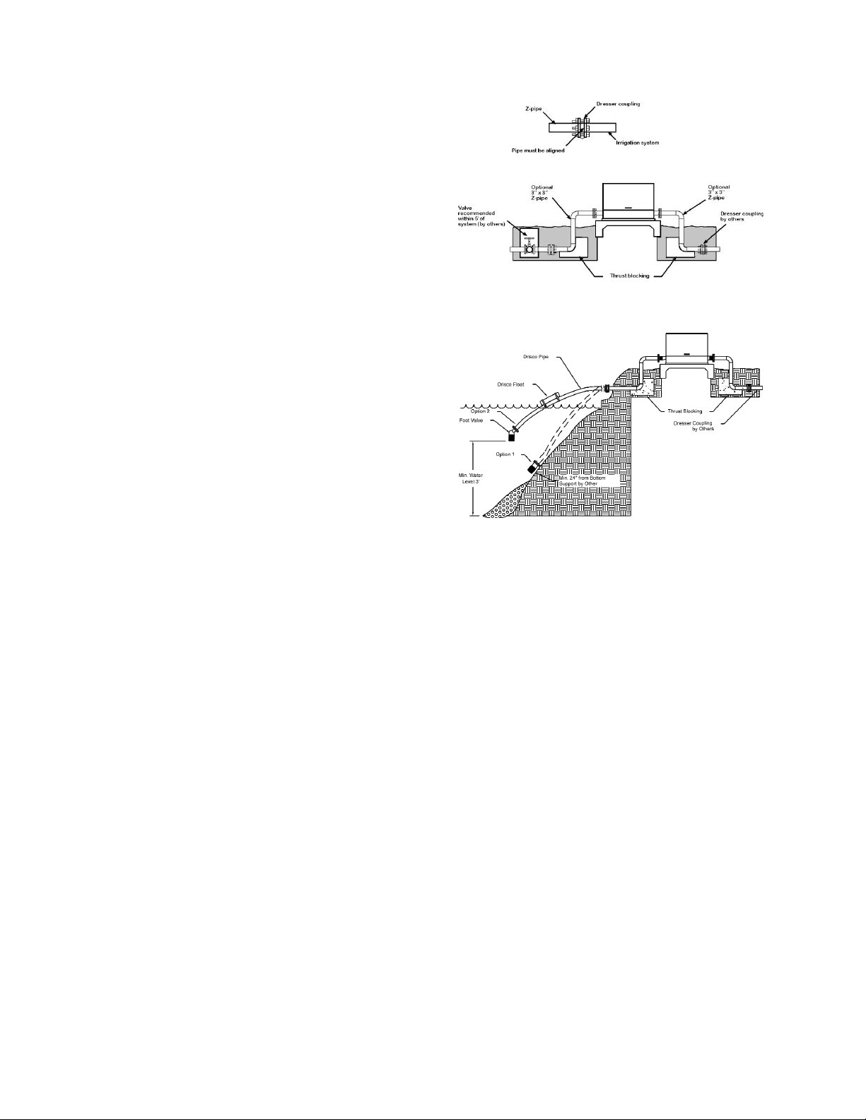
SUCTION PIPING
Suction piping is perhaps the most sensitive and
demanding element of the pump station
installation. Proper suction piping can make the
difference between the pump station operating
properly or not working at all. The following rules
should be observed in the installation of every
suction assembly:
Page 14

10
A. Piping should be sized in accordance with
the architect, engineer or factory's
direction.
B. Piping should be constructed of spring
reinforced suction hose, steel or high
density poly pipe. All joints should be
fusion welded or flanged and pressure
tested to ensure a leak proof connection.
Threaded fittings should be installed with
ample Teflon pipe joint compound and
pressure tested with air using a soap
solution to check for leaks. PVC pipe with
glued or gasketed fittings should never be
used.
C. Piping should be well-supported in order
to eliminate piping strain on the inlet of the
station. Piping strain can be tested simply
by disconnecting the piping connection
closest to the station inlet after the suction
assembly is complete. If the disconnected
piping shows signs of misalignment and
requires force to reconnect, the pump is
experiencing piping strain. Correct this
condition by changing the existing
supports or by adding more supports until
the suction piping connects to the pump
inlet with no misalignment.
D. All piping reducers should be eccentric
with the flat portion of the reducer
positioned on top. Isolation valves should
not be installed in pump suction piping.
Use a minimum number of elbows
(preferably no more than two) in any
suction pipe. These elbows should be 45degrees, if possible. A 90-degree elbow
may be used if positioned properly. The
elbow closest to the pump inlet should
have a section of straight pipe at least six
pipe diameters long between the elbow
and the pump inlet (Example: 4" pipe
requires 4" x 6 = 24" long piece of straight
pipe between the elbow and the pump
inlet).
E. Pump stations that lift water from a lake or
pond must be installed with a foot (check)
valve at the end of the suction pipe. The
valve should never be installed above
ground and should always be equipped
with a properly sized intake screen. The
foot valve shall be constructed of
aluminum and shall contain a rubber
flapper which sets on a machined
aluminum surface to provide a tight seal.
Ample space shall be provided for the
flapper to fold back out of the liquid
stream, keeping friction loss to a
minimum.
F. The foot valve should be positioned at
least 4 pipe diameters below the lowest
possible water level and never lay on the
bottom where silt and sand could be
sucked into the pump. It should always be
mounted in a vertical position.
Note: Never mount a foot valve at an angle
other than vertical since the valve may
experience difficulty in closing securely.
Locate and protect the suction intake from algae
or other floating material with a cleanable screen
or a diversion structure.
Note: Please consult the factory if the pump is
to take its suction from a stream or river that
might experience suspended silt, sand or other
abrasive materials. Special filters or intake
structures may be necessary to protect the
pump from premature wear and failure. The
presence of any abrasive materials will void
the factory warranty.
Page 15

11
Figure 6: Proper suction lift principles
Figure 7: Improper suction lift application
Page 16

12
DISCHARGE PIPING
Like the suction assembly, the discharge piping
requires adherence to certain rules and conditions
in order to minimize future problems. The following
list should be observed when designing and
installing the discharge assembly:
A. Discharge pipe should be constructed of
screwed or welded steel pipe.
B. The piping should be constructed in a Z"
configuration with 45 or 90-degree elbows.
The elbow located underground must be
protected against movement by a
concrete thrust block. The concrete form
should be positioned on the station side of
the elbow so that pipe movement is
prohibited in that direction. At least ½ yard
of concrete should encase this elbow and
extend to the virgin soil surrounding the
elbow and pipe. Please note: piping must
be supported properly prior to pouring the
concrete thrust block in order to ensure
piping strain is not present at the pump
discharge. Piping train on the discharge of
the pumps station can be checked in the
same manner as the suction piping strain
described earlier.
C. Connecting the steel pipe to PVC mainline
should be accomplished with a gasketed
transition coupling. Solid connections,
such as flanges or screwed fittings, should
be avoided. Transition couplings are
available at most irrigation supply houses.
Figure 8: Proper installation of pump
station discharge.
ELECTRICAL CONNECTIONS
The pumping system is pre-wired at the factory
and includes all internal wiring necessary to
function. For relay start systems, the customer
must still wire any external controllers and devices
to the relays inside the control panel. The only
electrical connection required in the field is the
main disconnect located in the station control
panel. Electrical cables from the power company's
meter or distribution panel are to be connected to
the top lugs of this main disconnect panel.
DANGER
Electrical wiring poses the danger of
hazardous voltage. Contact with live
electrical connections can cause shock,
burns or even DEATH. All electrical
connections should be made by a qualified
and licensed electrician and then inspected
by local code compliance authorities.
All electrical connections in the control and
disconnect panels are tightened prior to the
pumping system leaving the factory. However,
these connections can become loose during
transit and must be checked before energizing the
pump station. Your electrician should be
requested to perform this task and should be
directed to tighten all high and low voltage
connections, terminal strips and power lugs.
It is important to ground the station properly as
required by code. The electrician installing the
incoming power cables should also provide this
ground connection inside the main disconnect
panel.
CAUTION
In order to ensure the proper operation of the
station's electrical surge control devices it is
important to install proper grounding close to
the station.
The power company's grounding alone may not be
sufficient and additional ground rods may be
needed to ensure adequate protection. The quality
of this ground should be checked by a factory
certified technician or electrician and should not
exceed 20 ohms resistance.
Page 17

13
START-UP AND ADJUSTMENTS
Floboy Pumping Systems are pre-tested in the
factory and all controls are adjusted for the
operating conditions specified. However, there are
certain checks that must be performed prior to
energizing the pump station in order to prevent the
possibility of component damage. These voltage
checks can be performed by a qualified, licensed
electrician.
The required checks, procedures and adjustments
are as follows:
POWER CHECK
DANGER
Electrical wiring poses the danger of
hazardous voltage. Contact with live
electrical connections can cause shock,
burns or even DEATH. All electrical
connections should be made by a qualified
and licensed electrician and then inspected
by local code compliance authorities.
Have a licensed electrician check incoming
voltage to make certain it is in the range specified
and its variance and imbalance are within
acceptable limits. The pump's motor, starter and
wiring are sized for a particular nominal voltage;
either 120, 208, 240 or 480 volts. Voltage is
checked with a calibrated volt meter. On a threephase system (power is supplied with three or four
wires) there will be three fuses in the main
disconnect panel, A, B and C. It is important that
your electrician or technician check the voltage
between each fuse pair, i.e. A to B, B to C and A
to C. These voltage readings should be analyzed
in accordance with the following formulas:
VOLTAGE VARIANCE
1. Average the three voltage readings
2. Subtract the nominal voltage from this average
3. Divide the difference by the nominal voltage to
arrive at a percent variance
4. The maximum acceptable level for voltage
variance is 5%
EXAMPLE:
Assume the actual voltage readings on a nominal
480 volt system are:
A-B = 485 volts, B-C = 492 volts, and A-C = 472
volts
The average voltage is (485+492+472)/3 = 483
volts
The percent voltage variance is (483-480)/480
=.00625 or.625%
VOLTAGE IMBALANCE
1. Average the three voltage readings
2. Find the reading which has the widest deviation
by subtracting the average from each reading
3. Choose the largest difference and divide it by
the average voltage to arrive at a percent
imbalance
4. The maximum acceptable level for voltage
imbalance is 2%
EXAMPLE:
Assume the voltage readings described above
are:
A-B = 485 volts, B-C = 492 volts, and A-C = 472
volts
The average voltage is (485+492+472)/3 = 483
volts
The largest difference is (A/B - Avg.) 485-483 = 2
volts
(B/C - Avg.) 492-483 = 9 volts
(A/C - Avg.) 483-472 = 11 volts
The percent voltage imbalance is: 11/483 =.0228
or 2.28%
In this particular example the voltage variance is
acceptable while the voltage imbalance is not. If
your calculations show either result to be beyond
the acceptable limits noted, you should contact
your power company and have the power
corrected. Failure to do so could result in motor
current imbalance and excessive heat which
reduces the motor's lifetime.
PUMP PRIMING
As noted earlier, priming the pump is the process
of filling the pump's volute case and suction piping
in order to facilitate the pump's ability to move
Page 18
14
water when the motor is energized. For pump
stations whose inlet is supplied with water under
pressure or from an elevated reservoir, the priming
process is not required other than the removal of
trapped air in the suction pipe. A petcock on the
top of the pump volute should be opened to allow
air to escape and the volute to fill with water. Once
the air has completely escaped, close the petcock.
If the pump station sits above its water source
such that a foot valve is required, the pump will
require priming. Remove the cap from the 3/4"
pipe at the station inlet and fill the suction pipe
using a garden hose or bucket. When the pipe
overflows and water is maintained at the top of the
fill pipe for several minutes, the pipe cap can be
re-installed and tightened. You may have to repeat
this filling process two or more times if air is
trapped anywhere in the suction piping. The
presence of air will cause the pump to instantly
lose pressure once the discharge valve is opened.
PUMP ROTATION
CAUTION
Caution: Always ensure that the pump is
primed prior to checking rotation. Failure to do
so can damage the mechanical seal located in
the motor end of the volute case. These seals
are very sensitive and can be destroyed if
allowed to run dry, even for a very brief period
of time.
It is important to note that the pump is designed to
rotate in a given direction. On most pumps the
proper direction of rotation is noted by an arrow
cast or painted on the exterior of the volute casing.
In the absence of this arrow, one can determine
the proper direction of rotation by observing the
pump from the motor end. Rotation should always
be in a clockwise direction when viewing the pump
from this vantage point. Pump rotation can be
checked by momentarily energizing the motor and
observing the shaft between the motor and the
pump.
Three-phase motors can rotate in either direction.
Checking pump rotation by briefly energizing each
motor is accomplished with a two position switch
labeled "Off/On". The switch is located on the
control panel door and it determines the pump's
mode of operation. The procedure for performing
this check is to first turn the main disconnect on
the outside of the station enclosure to the "On"
position. Next, press the manual button on the
front of the controller, then turn the "Off/On" switch
from "Off" to "On". For the VFD Pump, the motor
speed may need to be increased to approximately
10-20% before the motor will turn. Once motor
rotation has been determined, turn the switch back
to "Off". Reverse rotation of centrifugal pumps is
not damaging but performance and efficiency are
poor and long periods of operation will cause
overheating. Running the pump for a minute or
two to determine rotation will not harm the pump.
PM Pump rotation may be more difficult to
determine. Most PM Pump models motor-pump
coupling is not visible, so a performance check is
required to determine proper rotation. With the
pump primed and the station isolation valve closed
and the controller in “Manual”, turn on the PM
Pump switch (Must be cycled off-then-on if the
switch is on when the change to manual is made).
Note the system pressure. The pump should have
no trouble generating set point pressure in the
discharge manifold. If pressure does not increase
when the pump is started, first verify that the PM
Pump isolation valves are open, that the station
discharge isolation valve is closed, and the
petcock on the discharge pressure gage is open.
If the pump still fails to produce, verify the PM
Pump discharge pressure reducing valve is not
adjusted all the way out. (If set point pressure is to
be higher than the factory setting, this valve may
need to be reset). If the pump still fails to produce,
change rotation of the pump and retest.
WARNING
Caution: Make certain the power is turned off
at the main disconnect switch prior to
changing any electrical leads.
If the rotation is wrong, it can be corrected by
reversing any two leads on the bottom of the
motor starter or VFD (example: move wire A to the
B location and wire B to the A location). Single
phase motors will require internal rewiring which is
best performed by a Flownet technician, and is
normally only required after motor replacement.
Page 19

15
Figure 9: Confirm rotation by making sure motor is
operating in the direction of the motor tag
SYSTEM PRESSURIZATION
With the system isolation valve on the discharge of
the pump station almost fully closed, turn the
Off/On switch to the "On" position. When the pump
starts, you should notice an immediate increase in
pressure on the manifold pressure gauge. If the
pressure does not rise to at least the operating
pressure of the system, turn the Off/On switch to
"Off" and repeat the priming process described
earlier. Otherwise refer to the "Troubleshooting"
section of this manual or contact the factory for
assistance.
CAUTION
If you open the system isolation valve too
quickly, the pump may instantly lose prime and
will require repeating the priming process.
Leave the station isolation valve in a slightly
cracked state until you are certain water is flowing
into the discharge piping. On irrigation systems it
is a good idea to open several sprinklers at the
remote end of the system. When water begins to
emerge from these heads the system is
reasonably full and the pump station isolation
valve can be gradually opened to its full position.
When starting a centrifugal pump for the first time
it is a good practice to stay close to the pump for
the first few minutes of operation. If you notice
conditions such as smoke from the motor, unusual
odor, loud noises, etc., turn the pump off
immediately and consult the factory. In some
cases the pump may sound like it is pumping
marbles or rocks. This noise may be the sign of
mechanical problems or it may be a hydraulic
phenomenon known as cavitation occurring inside
pump. Cavitation is a condition that may
permanently damage the pump if allowed to
continue. It is usually caused by improper suction
installation or by over demanding the pump. It is
not uncommon to experience cavitation when
filling the discharge piping since empty piping
encourages pump over demand if the station
isolation valve is opened too far or too quickly.
Should you notice this sound, gradually close the
isolation valve until the noise intensity subsides.
Once the system approaches full design pressure,
the cavitation noise should disappear. If throttling
the system isolation valve makes no difference in
the noise intensity, turn the pump off and consult
the factory.
PRIMING LINE ADJUSTMENT
On pumping systems requiring a foot valve in the
suction, a priming line valve is used to apply a
seating pressure to the suction pipe when the
pump is not operational. This valve is set for 30 psi
but can be adjusted if so desired. Turn the valve
adjustment screw clockwise to increase pressure
and counterclockwise to decrease.
OVERLOAD TRIP ADJUSTMENT
Every motor starter assembly uses an electronic
sensor that monitors the motor current. If the
current exceeds a safe limit, considered to be a
point where the motor is overloaded, the sensor
shuts the motor off. The current limit is factory
preset but can be adjusted as noted by the
calibrated scale along side the adjustment screw.
CAUTION
This adjustment should be made by a qualified
technician only. Improper adjustment of this
setting can jeopardize motor lifetime and affect
system warranty.
The overload should never be adjusted above the
motor's full load rating. This rating is stamped on a
motor identification tag fixed to the motor housing.
Make certain the motor full load current rating
corresponds to the correct operating voltage since
multiple voltages and their corresponding current
ratings may be noted on the same tag.
Page 20

16
STATION OPERATION
This section covers the sequence of operation for
your station including: Door Switch Operation,
Automatic Operation, and System Safeties.
DOOR SWITCH OPERATION
Individual Pump Switches
Allows operator to select which pumps
operate:
NOTE: Pumps have an OFF/ON switch.
OFF Selected pump does not operate,
regardless of any other switch position.
ON Selected pump will operate,
provided the system switch is set to AUTO
or MANUAL
OPERATIONAL SETTINGS IN THE HMI
Note: HMI Stands for “Human Machine Interface”
Auto-Manual Select
The Auto-manual Control (circled) resides
on the default screen.
Press the center arrow to move between
auto and manual mode. Pump must be
switched off, then on when changing
mode to manual or pump will not start.
LDP Override
This position prevents a low-discharge pressure
fault from shutting down the pump station. Use the
LPD OVERRIDE “Y” position during the initial pipe
filling and when restarting the system from a depressurized condition in MANUAL or AUTO mode.
Access is gained to this item by pressing the
“Manu” button, accessing the menu then selecting
“Safeties”.
Reset Control (F5)
This control allows the operator to clear (Reset)
any faults within the system once the cause of the
fault has been cleared.
The safety in effect will be shown in the lower
“Status” portion of the screen. You will also be
instructed to press F5 to reset the fault.
Resetting Faults
Faults must be reset by the reset control.
Pressing the reset control clears all fault counters.
If the fault lamp/message does not go out after
resetting, the cause of the fault is still present and
must be resolved before normal operation can
continue.
Page 21

17
AUTOMATIC OPERATION
Overview
The primary benefit of Variable Speed Pumping
(VSP) Systems is to ensure surge-free starts and
stops while maintaining a constant down-stream
line pressure with no mechanical pressureregulating valve. This minimizes pipeline failures
due to surges and, not incidentally, reduces the
utility bill for the station.
Automatic operation is selected by manual-Auto
control on the HMI. In automatic operation, all
pump activity is determined by the controller. The
position of the individual pump switch lets the
controller know whether or not it is available to
run. In most cases, all pump switches are in the
ON position. When a pump or a motor is removed
from the system, turn the pump switch OFF, and
the controller will not try to run that pump.
The controller brings one pump on at a time in
order to satisfy the start criteria (usually set point
pressure). Some stations are designed to start and
stop the pumps based on remote start signals or
flow. The standard start and stop sequence is as
follows:
Pressure below set point to start
Combo 1
-3 PSI
Delay time to start Combo 1
0 SEC
Pressure above set point to stop
Combo 1
5 PSI
Delay time to stop Combo 1
5 SEC
Pressure below set point to start
Combo 2
-5 PSI
Delay time to start Combo 2
3 SEC
System Charging Mode
If there are no heads open, and the pressure is
within the defined range of operation, pressure
may slowly drop due to system leakage, or other
small demands. A PM pump option is available to
address this issue. Not all stations include a PM
pump. System is configured as follows:
System Mode: AUTO
All Individual Pumps switches: ON
LP Override Setting: Off (Low Discharge Pressure
fault enabled)
NOTE: As downstream pressure drops to more
than 5 PSI below set point, the PM pump starts
up. It runs until the system pressure builds up to 5
PSI above set point, and then shuts off.
Two issues can come into play here. One is cycle
time. This refers to the number of times an hour
that the PM pump starts and stops (one cycle). If
the amount of cycles is excessive, either the
system leaks have to be repaired, or the start/stop
parameters need to be tuned (normally by
dropping the pressure below set point to start or
increasing the pressure above set point to stop).
WARNING: Excessive Run Time Hazard
Excessive stop times, or stop pressure setting
can cause system over-pressurization, pipe
damage, and potentially cause personal injury.
Consult your service technician or the factory if
you are unsure about any settings.
Failure to follow these instructions could result in
serious personal injury or death, or property
damage.
NORMAL OPERATION
Normal Operation occurs when heads are turned
on, or a demand for water exists. System is
configured as follows:
System control switch: AUTO
PM Pump switch: ON
Pump 1 switch: ON
LP Override setting: “N” (Low Discharge
Pressure fault enabled)
When the pressure drops 5 PSI below set point,
the PM pump starts and continues to run until the
pressure is 5 PSI above the set point. When this
pressure is reached, the PM pump turns OFF. If
the pressure continues to drop to 10 PSI below set
point, the VSP starts and the PM pump turns OFF.
This is the operation sequence for Combo 1.
When the VSP starts, the startup ramp in the
program lowers the set point to 2 PSI above the
actual line pressure. The VFD adjusts the speed of
the VSP to maintain the discharge or downstream
Page 22

18
pressure at the set point. This is the operation
sequence for Combo 2.
When the flow decreases, the VFD slows down to
maintain a constant discharge pressure.
Eventually as the speed decreases, a set point is
reached where the VSP is not pumping any water.
Because the VFD speed keeps dropping as the
flow decreases, the discharge pressure would
never get above the set point. In this situation, the
VSP would "idle," pump no water, and would
never turn off. To shut down the VSP, the system
initiates the "Speed Test" whenever the flow is
below a predetermined value for 15 seconds. The
program then lowers the set point by 5 PSI. If the
VFD speed falls below a predetermined value and
the pressure remains above the reduced set point
for 15 seconds, the VSP turns OFF.
MANUAL VFD OPERATION
Overview
Manual operation is selected by the system mode
control on the HMI. In manual operation, all pump
activity is controlled by the individual pump
switches. The speed of the VFD pump is
controlled by the speed slider on the main screen.
The PM Pump will run in XL mode (at full speed).
The LP Override setting enables or disables the
low-discharge pressure fault.
NOTE: Manual operation is rarely used. However,
it does allow for operation of individual pumps for
testing purposes.
Sequence of Operation (performed in
order)
All Individual Pump switches: OFF
Low Pressure Override setting: “Y” LDP
Override (Low Discharge Pressure fault
disabled). If initial system pressure is high
enough, disable Low Pressure Override
(Set to “N”).
System control mode: MANUAL
Pump 1 switch: ON
Speed Potentiometer: Press up-arrow to
increase speed, or press “Set” to allow
entry of speed directly (in %). Adjust as
required for flow rate / pressure required.
NOTE: When done, turn OFF all pump switches
and place system control switch in OFF. Return
LP Override setting to N. If the station can be run
in Automatic mode, return the system to AUTO
and turn ON all pump switches.
Page 23

19
CONTROLLER BYPASS OPERATION
Overview
This is an abnormal operating mode and would be
used if the controller was not operable and there is
need to irrigate.
WARNING: Controller Bypass Hazard
This mode of operation should be used as a last
resort. Constant operator monitoring is
REQUIRED when this mode is used. No safeties
function in controller bypass, and damage to your
piping or property could occur.
Failure to follow these instructions could result in
serious personal injury or death, or property
damage.
System Operation (performed in order)
All Individual Pump switches: OFF
Using the VFD keypad located below the
pump switches on the door, Set the
following parameters:
1102 - EXT2 (7)
3018 - Not Sel (0)
4011 - Verify set point
4023 - Verify Min Speed
Pump 1 switch: ON
Verify operation before leaving
unattended.
SYSTEM SAFETIES
Overview
The program in the PLC protects the system by
shutting down in either of the “Auto” or “Manual”
Modes of operation if it detects any of the following
problems:
Fault Reset
All faults are cleared by pressing the Reset control
(F5) on the HMI, or by re-arming individual pump
faults by turning the individual pump switch to the
OFF position, and then back ON.
Table 1: Safeties
Low Discharge Pressure
The pressure transducer located in your station
discharge line communicates the downstream
pressure to the controller. The controller monitors
downstream pressure to determine if the pressure
is below the allowable range.
The standard program defines low-discharge
pressure as being 80% of set point pressure. This
setting is in gage pressure, not in reference to set
point. There is a time delay of 300 seconds
(adjustable) before the station faults that is
designed to give the system time to build pressure
beyond this point. The values might vary on your
station.
If the discharge pressure remains below the Low
Pressure set point for longer than 60 seconds, all
pumps are shut down. The red station fault light on
the station comes on, and the display indicates
that a "Low Discharge Pressure Safety" has
occurred.
This fault does not automatically reset. To clear
the fault, press the Reset control on the HMI.
If the pump station is simply unable to keep up
with the demand, shut the station down, and
determine the nature of the problem. Consult the
Troubleshooting section of this manual for
assistance.
High Discharge Pressure
As with the "Low Discharge Pressure" fault, the
controller monitors downstream pressure to
determine if the pressure is out of range, or above
the allowable limit.
The standard controller program defines highdischarge pressure as being 15 PSI above set
point pressure (set in gage pressure without
Alarm or Fault
Low Discharge Pressure
High Discharge Pressure
Low Inlet Pressure (Optional)
Loss of Prime (Optional)
Low Level (Optional)
Individual Pump Faults
VFD Fault
Page 24

20
reference to set point). There is a time delay of
60 seconds, before the station faults that is
designed to give the system time to adjust the
pressure to below this point. These values might
vary on your station.
Based on the values above, if the discharge
pressure remains 15 PSI above the set point for
longer than one minute, the station shuts down.
The red station fault light on the station comes on,
and the display indicates a “high pressure Safety”.
NOTE: At this point, shut the station down, and
determine what the problem is. Consult the
Troubleshooting section of this manual for
assistance.
To clear the fault, press the Reset control (F5).
Low Inlet Pressure
This optional safety is usually used on floodedsuction booster pump applications.
Normally, a pressure switch monitors the inlet
pressure on the "suction" side of the pump. This
switch is located in a box on the lower left side of
the control cabinet. The switch is used in
conjunction with a relay to inform the controller
that it is unsafe to run. Setting the low inlet
pressure condition is accomplished by physically
adjusting the pressure switch. There is a 20
second time delay in the PLC.
Once the inlet pressure drops below the switch
pressure setting, all pumps shut down after a 20
second (adjustable) delay. The red station fault
light comes on, and the display indicates a "Low
inlet Pressure Safety”.
WARNING: Low Inlet Pressure – Station
Shutdown Hazard
At this point, shut the station down, and
determine what the problem is. Consult the
Troubleshooting section of this manual for
assistance.
Failure to follow these instructions could result in
serious personal injury or death, or property
damage.
There are two dials on the pressure switch. The
one on the top is the correct one to adjust. Turn
clockwise to increase the pressure set point,
counter-clockwise to decrease.
CAUTION: Delta Pressure Setting Hazard
Do not adjust the bottom dial. This is a delta
pressure setting, and is not used. This dial must
be adjusted fully counter-clockwise (0 position). If
you are having trouble with your pressure switch,
always verify that this dial is in the 0 (fully
counter-clockwise position) before adjusting the
top dial.
Failure to follow these instructions indicates a
potentially hazardous situation, which, if not
avoided, may result in property damage.
CAUTION: Minimum Pressure Setting Hazard
The pressure setting is based on the minimum
inlet pressure that the pump can safely operate.
Do not lower the pressure switch setting without
consulting the factory.
Failure to follow these instructions could result in
serious personal injury or death, or property
damage.
Loss of Prime
This optional safety is usually used on end-suction
centrifugal pump applications.
A level probe is placed in the suction piping at a
predetermined level. This probe works in
conjunction with a relay to inform the controller
that it is unsafe to run. Fault usually signifies a
malfunctioning foot valve.
After a few seconds, all pumps shut down. The red
station fault light comes on, and the display
indicates a "Loss of Prime fault"
NOTE: At this point, shut the station down, and
determine what the problem is. Consult the
Troubleshooting section of this manual for
assistance.
To clear the fault, press the Reset button.
CAUTION: Equipment Damage Hazard
Do not attempt to bypass this safety, as pump
damage will occur.
Page 25

21
INDIVIDUAL PUMP FAULTS
Pump faults are usually caused by the thermal
overload tripping, or circuit fault that causes the
pump NOT to start when requested.
Overload Protection
Overload Protection is standard on all pump
stations. The overload is a safety device that shuts
the motor down when amperage exceeds the set
point of the device.
If the motor amperage exceeds the overload set
point that pump shuts down after a time delay.
This delay time is inversely proportional to the
overload amount. In some instances, an individual
pump can trip without shutting down the entire
system if another pump is available to operate. If
so, the controller will automatically bring the
available pump on line. The controller will indicate
a fault for the specific pump.
WARNING: Overload Hazard
The overloads are located inside the control
panel. All safety procedures must be adhered
to during the any adjustment or resetting
process. Improper procedures or failure to
use proper safety procedures could result in
death or serious injury.
Resetting the overload is accomplished by
pushing in the blue Differential Overloads button
on the right front face of the device, and rotating it
approximately an eighth of a turn clockwise
(applies only to PM Pump).
Adjustment of the overload set point is performed
using the blue dial on the left front face of the
device.
Once the overload has been reset, individual
pump faults require turning the individual pump
switch to the OFF position, and then back ON (rearming).
High Pump Temperature (Optional)
High pump temperature utilizes a temperature
probe inserted into the pump discharge piping.
The probe trips when the water temperature
reaches 120°F, and then immediately shuts down
the pump. “PM Pump High Temp” or “Pump 1
High Temp” will show on the HMI.
The temperature probe automatically resets at
105°F. At that time, the pump can be re-armed,
and pump operation can continue.
NOTE: If the pump continues to shut down for this
issue, shut the station down and determine what
the problem is. Consult the Troubleshooting
section of this manual for assistance.
VFD Fault
The VFD sends a fault signal directly to the
controller. The display shows, "VFD Fault" and the
red station fault light comes on. To determine the
nature of the problem, you must use the VFD
keypad display and review the fault/alarm history.
This procedure is outlined in the VFD section of
this manual. A list of all inverter fault/alarm codes
is found in your VFD manual.
Once you have determined what the VFD
(inverter) fault is, and have cleared it, press the
station Reset button to clear the alarm shutdown
status.
NAVIGATING THE CONTROLS
OVERVIEW
The Floboy controller is a combined touch-screen
interface (HMI) and controller. The device
communicates with the VFD for pressure and flow
readings, inputs (pump switches, safety switches,
etc), and outputs (Fault light, PM Pump contactor,
etc).
All control decisions are made in the controller,
including PID control, pump start/stop decisions
and safeties. Settings for these decision
processes are available in the controller. There
are 6 keys to the right of the controller screen.
These are quick access keys that quickly allow
access to menus and are also provided special
functions in some screens. F5 is the “Reset
Control” and is used to reset system safeties.
Page 26

22
Figure 10: Floboy controller.
The “Menu” key provides access to the slide-out
menu which can be touched directly for navigation
and also serves as a reminder of the function keys
definition in the context of the current screen.
The main screen shows pressure, flow, set point
pressure, VFD speed, pumps status, fault status
and provides access to the “Manual” and
“Automatic” mode selection.
Figure 11: Main Screen
The Flow window will show either a flow rate, if an
optional flow meter was purchased with the
system, or a flow indication, indicating “No” for no
flow, and “Yes” for flow> 0.5 ft/sec.
The lower left corner of the screen will display fault
information and other status indications.
PUMP STATUS INDICATORS show the status of
each pump.
Figure 12: Pump Status Indicators
PRESSURE SET POINT ADJUSTMENT
CAUTION: Equipment Damage Hazard
Be careful not to set the value too low for the
pump you are using, nuisance overloads can
occur. Also, do not set the value too high for your
systems piping or damage may occur.
Touch the numeric value for the set point:
Figure 13: Pressure Set Point
The password screen for set point will come up.
Figure 14: Set Point Password Entry Screen
Touch the button next to the password value.
Enter “1234” for password and press enter.
Page 27

23
Figure 15: Entering the password for the set point
screen
This allows the user to edit the set point.
Touch the button next to the Set point value:
Figure 16: Changing the set point
Change the set point as required. Be careful not
to set the value too low for the pump you are
using, nuisance overloads can occur. Also, do not
set the value too high for your systems piping or
damage may occur.
TRENDS AND ALARMS
Press the Graph button to access the
history/performance graph. Scroll to access
historical data up to 2.3 days of data for pressure,
Flow, Set point and VFD Speed.
Figure 17: Performance Graph
Press the Alarm button to view up to 32 previous
alarms.
Figure 18: Alarms Screen
Alarms are shown as shown in figure 15 below.
Figure 19: Alarm Description
Page 28

24
Pressing the Menu button from the main screen
provides access to the menu system.
Figure 20: Menu
Access to the main functions of the controller is
available from the menus.
Figure 21: Totals
TOTALS: provides access to the Flow totals
(optional flow meter required) and pump hour
meters.
Figure 22: Pump Control
PUMP CONTROL: Allows access to pump start/stop
parameters for station tuning.
START SETTINGS. Select combo and parameters
to set via buttons at top of screen. Pressure is in
reference to set point. Flow rate is used for Flow
Start systems.
Figure 23: Stop Settings
STOP SETTINGS: Pressure is in reference to set
point, flow rate is used when flow stop is
required/configured.
Figure 24: Pump Control, Combo Selection
F3 allows user to change the combo being
adjusted. Note the combo number being adjusted
is shown in the black box on the right-hand side of
the screen.
Page 29

25
Figure 25: Speed Test
SPEED TEST: Delay is how long the controller
waits before initiating speed test (after all other
shutdown parameters are satisfied). Step delay
controls how quickly the VFD speed is reduced, to
detect 0 flow. If VFD speed reaches minimum
speed (set under PID, shown later), then the
controller will shut down the pump. Step size is
the % speed decrease for each step. To “smooth
out” speed test, set Step delay lower and step size
lower. To quicken speed test, set step delay
higher and/or step size higher.
SAFETY:
Figure 26: Safety
The safety functions are controlled in this screen.
Delay controls how long the safety will take to time
out. Set point for Low Pressure and high pressure
are in gage values and not in reference to set
point. Low Pressure override is also found in the
safety menu.
Figure 27: Safety, Others
Inlet water faults are controlled under “Others”.
Short times should be used as these faults can
cause serious damage if the timers are set too
long. 5 seconds is all that is required. High Pump
Temp is also controlled here. The delay is how
long between a high pump temp signal and the
pump is shut down. 5 seconds is all that is
required. The Hold off time controls how long the
pump must run before the HPT is honored. This
prevents exposed inlet piping from causing a HPT
safety on startup due to solar heating of the water
in the pipe.
Figure 28: Panel Configuration
PANEL CONFIG: Used to set screen contrast and
time/date in the controller.
SYS CONFIG (Password required, technician
access only):
PID PARAMETERS, pump configuration and other
factory/technician access parameters are
configured here.
OTHER SETTINGS (Password required, technician
access only): Safeties and other control features
are controlled here.
Page 30

26
MAINTENANCE
Maintenance is an investment that will pay
dividends in the form of improved reliability and
durability. Site maintenance checks are a matter of
day to day, week to week care that is important to
the proper operation of the pumping equipment.
Periodic equipment checks will ensure that the
recommended lubricants, fluids and service parts
are available and planned for. Flowtronex
recommends Preventative Maintenance be
performed quarterly.
DANGER: Personal Injury Hazard
Performing maintenance work on your pump
station can be dangerous. You face the risk of
electrical shock or related injuries, and must be
trained in the danger of electricity. If you have
any doubt, have a qualified technician do the
work. Contact the factory for the closest
authorized Flownet service office to you.
Failure to follow these instructions will result in
death or serious injury.
REGULAR MONTHLY MAINTENANCE
INTERVALS
Heat exchanger:
Verify that the flow through the heat exchanger is
a solid streamline out of the exhaust line into the
wet well. Too little flow reduces cooling capacity.
Too much flow can waste water and reduce the
life of the core. 2 gpm is all that is required.
Control panel:
Using the operator interface, verify that all the
buttons operate properly. Also review the station
operation, fault history, and data log for station
operation.
Verify that all surge devices are visually sound.
Check the surge device for the station (mounted
on the back of the control panel). Black soot on or
around the device indicates that it has taken a
surge and needs to be replaced.
Motor lubrication:
If you have a grease filled bearing, ensure that
grease is not all over the inside of the motor and
down in the bottom of the motor. This could be a
sign of over-filling. Refer to the motor
manufacturer's lubrication instructions.
Pumps - horizontal:
For a horizontal pump, verify that the mechanical
seal is not leaking between the pump and the
motor.
Sound and visual checks of whole station:
Just listen. Do you hear any odd sounds rubbing
or grinding or maybe even electrical arcing or that
something is in a bind? This can indicate a serious
problem.
There is going to be some harmonic vibration with
the pumps and motor. We are looking for
excessive vibration or noise. Can you see a bend
in the pump shaft? Do the motor and shaft shake
violently? This needs servicing immediately. Do
not operate pump if vibration is excessive.
Confirm that the building cooling and ventilation
systems are operating and clear of all
obstructions. Maximum operating range for
equipment is 40°C (104°F). Verify that water,
grease, oil, hardware, etc. are not leaking or loose
on the pump station.
Station skid:
Visually inspect for leaks in the station piping,
valves, and other components.
Visually inspect the piping and skid for any stress
cracks in the welds.
Visually inspect the station for loose or damaged
paint or areas of rust.
DANGER: Personal Injury Hazard
Pump station maintenance must be performed by
properly trained and qualified personnel. Hazards
exist for electrocution, shock, rotating
components, and pressurized components.
Failure to follow these instructions will result in
death or serious injury.
Page 31

27
WINTERIZING THE PUMP STATION
CAUTION: Equipment Damage Hazard
Your pumping system must be properly winterized before
storage. Failure to winterize the system could result in
damage to the pipes, valves, pumps, or other components.
Failure to follow these instructions indicates a potentially
hazardous situation, which, if not avoided, may result in
property damage.
Winterizing
1. Turn all enclosure switches to the OFF
position.
2. Open (turn off) all electrical disconnects to
the pump station.
DANGER: Personal Injury Hazard
The pumping system must be disconnected from the main
power supply before attempting any operation or
maintenance on the electrical or mechanical parts of the
system.
Failure to follow these instructions will result in death or
serious injury.
3. Close all the station discharge isolation
valves.
4. Close the pump station inlet isolation
valves.
5. Close all auxiliary equipment isolation
valves (if applicable).
6. Remove all connections from the heat
exchanger inlet and discharge. Force
water from the heat exchanger core with
compressed air.
WARNING: Pump Pressure Hazard
Pumping system must be isolated from the system and
pressure released before disassembly of any piping, valves,
or pumps.
Failure to follow these instructions could result in serious
personal injury or death, or property damage.
CAUTION: Compressed Air Hazard
Proceed with caution when working with compressed air.
Failure to follow these instructions could result in serious
personal injury, death, and/or property damage.
7. Connect hose to hose bib on the pump
station. The bib is usually found under the
discharge manifold for the pumps, or at
the end of the hydro-pneumatic tank.
Slowly, open the hose bib ball valve on
the pump station. Slowly, open all ball
valves on the pump station. Wait until
pump station pressure reads 0 PSI before
closing the hose bib ball valve.
8. Slowly, bleed pressure from the inlet
manifold using the ball valve or the hose
bib on the isolation ball valve on the
pressure gauge. Carefully, remove plug
from the inlet manifold and drain.
NOTE: Do this only if an inlet isolation
valve is installed and closed.
WARNING: Pump Pressure Hazard
Pumping system must be isolated from the system and
pressure released before disassembly of any piping, valves,
or pumps.
Failure to follow these instructions could result in serious
personal injury or death, or property damage.
9. If there is not an inlet isolation valve then
and you cannot drain the inlet line, close
all pump inlet isolation valves.
10. Remove the lowest plug on the pump
volute or open the pit cock valve to drain
all pumps completely.
11. Carefully, drain all filters and their
components, including the flush lines.
Spring Restart
Prior to restarting the pump station in the
spring:
1. Make certain that all tubing is replaced; all
connections are tightened; and check that
all the drain valves are closed.
2. Open all operating valves and verify that
the bonnet is tight.
3. Check that the drain plugs are installed in
pumps and piping.
NOTE: Contact Xylem Flowtronex PSI, if you
have further questions on winterizing your
pump station.
Page 32

28
TROUBLESHOOTING
1. If a troubleshooting step needs to be performed by a qualified person, it is labeled “To be performed by
a qualified person only.”
2. Steps that can be performed by unqualified persons are not labeled.
3. Qualified persons are those who have been trained in avoiding the electrical hazards of working on or
near exposed energized parts. Only qualified persons may open the electrical enclosure.
4. Unqualified persons are those with little or no such training.
LOW DISCHARGE PRESSURE FAULT
Cause
Cure
Flow rate greater than station capacity or
unable to pressurize the system in refill
mode (too many sprinklers on).
Adjust the irrigation demand as required.
Verify the pressure set point. Has this value been changed
from the original design? If the set point has been increased,
the available flow will be lower. Check the pump curve to
verify the pump performance.
A large break in the irrigation piping.
Repair the piping.
Low system pressure setting is too high.
Access “Menu->Safety->Low pressure: Set Point. This is a
gage pressure setting, not relative to set point.
Low system pressure safety time is too
short.
Access “Menu->Safety->Low pressure: Delay. Be careful not
to set this too high. 300 sec is normally the maximum, 60
seconds the minimum.
System pressure transducer sensing line is
valved off or clogged.
Check the ball valve position, and/or blow out line.
System pressure transducer failure.
Replace the pressure transducer (Flownet).
All pumps not running.
One of main pump switches in OFF position.
Consult the motor troubleshooting section if the motor won’t
start (see Motor Won't Start).
Main pump discharge isolation valve is
closed.
Open the valve.
Pump discharge check valve leaks.
Check for foreign objects holding the valve open. Replace the
check valve if it is damaged.
DSR or PRV is partially or fully open.
The pilot valve is set too low. Adjust as necessary.
The needle valve on speed control is screwed in (closed) too
far. Adjust as necessary.
There is air inside the relief valve cover. Bleed air off the valve
top.
The ball valve(s) at the inlet and/or cover tapping(s) are
closed. Open the valves.
The optional strainer at the relief valve inlet tapping is
clogged. Disassemble and clean.
There is an obstruction under the relief valve or pilot valve
seat. Disassemble and clean.
There is a leak in the relief valve diaphragm. Replace the
diaphragm.
Page 33

29
Bad relief valve or pilot valve seat. Rebuild or replace valve.
Low suction pressure or supply water
restriction.
Call the city if the city water pressure is lower than the normal
or published value. Check the supply piping for obstruction.
HIGH DISCHARGE PRESSURE FAULT
Cause
Cure
High system pressure setting too low.
Access “Menu->Safety->Low pressure: Set Point. Verify
is approx. 15 psi higher than set point. This is a gage
pressure setting, not relative to set point.
High system pressure time too short.
Access “Menu->Safety->Low pressure: Set Point.
Normal setting is 60 seconds. Do not extend too far or
piping damage may occur.
System pressure transducer failure.
Compare display readout to the pressure gauge.
Replace transducer (Flownet).
Isolation valve for DSR or main discharge is
closed.
Open the valve.
DSR will not open fully.
The pilot valve is set too low. Adjust as necessary,
15 PSI over set pressure.
The needle valve on the DSR is too far open; adjust as
necessary.
The ball valve(s) at the inlet and/or cover tapping(s)
closed. Open the valves.
The indicating stem is bent and/or sticking.
Irrigation demand is reducing too quickly.
Reprogram irrigation to stage down in steps.
LOW LEVEL FAULT
Cause
Cure
Clogged or shut off supply pipe.
Check the supply pipe for restrictions or closed valve.
Clogged inlet screen.
Check and clean the inlet screen.
Problem with level probes.
Inspect probes for correct insertion depth.
Look for dirty or corroded probes.
To be performed by a qualified person only.
Look for broken probes, probe holder, or wires.
To be performed by a qualified person only.
Check for loose or incorrect probe wiring.
To be performed by a qualified person only.
Verify ground continuity between the station and wet
well.
Level relay failure (inside control panel).
To be performed by a qualified person only.
Check relay for proper operation. Replace as required.
LOW INLET PRESSURE FAULT
Cause
Cure
Normally used on flooded suction horizontal or canned turbine stations
Page 34

30
Inlet pressure switch is set too high.
To be performed by a qualified person only.
Check the pressure switch setting.
(Located on lower left side of outside of enclosure.)
Pressure sensing line to pressure switch is clogged
or valved off.
Ensure the valve is open, and blow out line if
necessary.
Pressure is actually low – static.
If the city supplied water, check with them.
If the water is supplied by a tank, check the tank level,
and verify that the supply valve is open.
If equipped with a suction manifold strainer, clean as
required.
Ensure the supply piping not clogged or restricted.
Pressure is actually low – dynamic.
Ensure that the flow rate is less than the supply
capacity.
LOSS OF PRIME FAULT
Cause
Cure
Normally used on end-suction centrifugal pumps
System has lost prime or air is trapped in system.
Check the system for prime lead in the foot valve or
suction line.
Probe is dirty, corroded, or failed.
Clean or replace the probe as required.
Loss of prime relay failed.
To be performed by a qualified person only.
Check the relay for proper operation. Replace as
required.
VFD FAULT
Cause
Cure
Look at VFD keypad to determine specific fault and consult the VFD manual.
Codes identified below are some of the more common ABB 550 codes. Consult your specific VFD
manual for other drive applications.
Fault Code 2005 – Comm Fault.
Communications with the controller have failed.
Verify communications cable is properly plugged into the
controller. Verify connections at the VFD. (Note: This
fault may be caused by normal operation of the controller
using this fault to turn on the VFD Fault Light. If there is
no VFD Fault on the controller, but other faults are
present (Low pressure, high pressure, etc) then this fault
is normal and will be reset when the primary fault is reset
(F5).
Fault code 3 – dev overtemp (drive heatsink is
overheated).
To be performed by a qualified person only.
The VFD fan won’t come on. If there is no power, check
circuit breaker. Check for no continuity across transorb
(located at wire terminal strip). If the power is good,
replace the fan.
There is no water flow through heat exchanger. Make
sure both ball valves are open.
Water is leaking at the heat exchanger. Repair or replace
the coil.
Page 35

31
Fault code 2 – DC overvolt (intermediate circuit
DC voltage is excessive).
To be performed by a qualified person only.
Check the input voltage (AC) to the drive. If high, contact
the power company.
Fault code 6 – DC undervolt (intermediate circuit
DC voltage is insufficient).
To be performed by a qualified person only.
Check the input voltage (AC) to the drive. If low, contact
the power company.
Fault code 7 – AI1 loss (analog 1 input value is
less than minimum value).
This can be a nuisance fault. Set parameter 3001 = 0 not
sel.
Fault code 9 – motor overtemp (motor too hot,
estimated value).
This can be a nuisance fault. Set parameter 3006 =
1050, and 3007 = 115.
Fault code 22 – supply phase (ripple voltage in
the DC link is too high).
To be performed by a qualified person only.
Check the input fuses to the VFD. Review the phase
failure section above.
MOTOR WON’T START
Cause
Cure!
Pump Fault is indicated on Controller display
To be performed by a qualified person only.
The overload for that motor is tripped. Reset, adjust, or
replace as required.
Does the station have a high pump temperature option?
Check if the water temperature is greater than 120°F. If it
is, the pump is cavitating. If less than 120°F, the probe or
relay is bad.
To be performed by a qualified person only.
Does the station have the individual pump phase fault
option? See if the phase or voltage to motor is good.
Check the motor fuses. Replace that pump's phase
monitor as required.
Page 36

32
GLOSSARY OF TERMS
AC
Alternating Current. The voltage, and therefore current, constantly oscillates
positive and negative. For North America, the line frequency is 60 Hz. Some
other areas of the world use 50 Hz.
Across-the-line (XL)
Applying 100% of line voltage to a motor during startup and run. A simple large
relay with a contact for each power phase (for 3 phase) is used to control the
motor OFF/ON.
Analog
A signal that varies in some respect (voltage, current, frequency) in order to
convey the value of some real world information (i.e. pressure, flow,
temperature etc). A control system can take action based on the value of such
a signal. Internally, the signal will be converted to some number based on the
value of the signal.
Booster
A pump designed to increase the pressure of a pressurized irrigation line. This
is usually used to move pressurized water from a lower to higher elevation area
of the golf course.
Calibration
The act of or specific values used to scale the output of a measurement device
to read real-world values.
Chemical injection
The process of adding chemicals to irrigation water to fertilize or medicate
turfgrass.
Combo
A capacity level representing a predefined group of pumps on a station.
Normally Combos are defined as follows:
Combo 1
Normally the PM pump.
Combo 2
Lead pump. Normally the VSP.
Controller
Device mounted in panel to control system operation. Also called Touch Screen
or HMI.
Control valve
A valve designed to automatically open/close in order to maintain a specific set
point pressure, flow, or level.
Control variable
A value that a control system monitors in order to perform some useful function.
Cycle time
The number of times an hour that a pump (PM or main pump) cycles on and off.
Cycling
This condition occurs when conditions require a pump to start if no pump is
running, but require a pump to stop if a pump is running. This is excessive
starting and stopping of one or more pumps and can be damaging to the
equipment if allowed to continue.
DC
Direct Current. Such as a battery. The voltage is stable, and does not oscillate
(at least intentionally).
Digital
A simple ON/OFF condition. For example, the presence or lack of a 120VAC
signal on a wire is a digital condition.
Flooded suction
A type of system where the pumps (usually centrifugal) are fed by a pond or
other body of water at very low pressure (atmosphere, or just a few feet of
water column). Pumps for these systems must be carefully selected for low
NPSHR (Net Positive Suction Head Requirements) or cavitation and pump
damage can occur. Low inlet pressure safety is an excellent choice for these
systems.
Page 37

33
Foot valve
A device used primarily on horizontal lift applications to maintain pump prime.
Frequency
(Hz) The number of oscillations per second of any system. Typically used to
refer to electrical systems, such as AC power line frequency, or variable speed
drive output frequency. This frequency defines the speed of an AC motor.
GPM
Gallons per minute. Units of flow for US use.
Input
A way for a control system to detect real-world occurrences. These can be
digital or analog.
Inverter
Another term for Variable Frequency Drive (VFD). Actually, more correctly
applied to the output circuitry of the drive, which converts DC voltage to AC
voltage.
Lift
This refers to how high water must be "lifted" to reach the pump suction. Lift
stations have even harsher NPSHR than Flooded Suction systems. Loss of
prime safety is an excellent choice for these systems. Auto-re-prime systems
are available to help maintain a full suction line (CRD reprime, vacuum pumps).
Must-run time
The amount of time (in seconds) that the pump must run.
Output
A way for a control system to generate real world actions. An output can be a
120VAC signal to turn on a pump, or a varying 4-20 mA signal to control the
speed of a VFD. Many types of output are available.
Overload
A condition in which pumps are allowed to produce more flow rate than the
motor that drives them is designed for. Also refers to a device in the control
panel, which detects this situation and stops the pump in order to protect it.
Over-pressure accumulator
A counter that is used to determine the lag pump shut down sequence.
Overshoot
Indicates that the control variable has exceeded the set point value while the
controller was trying to correct it.
PM pump
Pressure Maintenance Pump. Handles very light flow rates and leaks to
prevent the main pumps from cycling.
Pressure reducing valve
(PRV) A control valve designed strictly for maintaining a specific downstream
pressure.
Pressure switch
This is a normally open or normally closed switch that changes output state
when the pressure exceeds the set point of the switch.
Pressure transducer
A device that converts actual pressure to a 4-20 mA signal that is input into the
PLC which converts it back to an actual pressure reading.
PSI
Pounds per square inch. Units of pressure for US use.
Re-arming
This refers to turning the pertinent individual pump switch to the OFF position
and then back to the On position to clear an individual pump fault.
Register
A memory location in a PLC. These can be used as configuration and storage
or temporary storage during mathematical calculations.
Relay
This is a normally open or normally closed device that changes output state
when it is energized or de-energized and sends or removes a 120VAC signal to
the PLC.
Set point
The desired situation for a control variable. If the user wanted the irrigation
system to operate at 120 PSI, that would be the set point for the controller.
Page 38

34
Speed test
The method used to shut down a VSP during normal automatic operation.
Temperature switch
This is a normally open or normally closed switch that changes output state
when the temperature exceeds the set point of the switch.
Units
Gives context to numbers in the PLC. Units describe what the number is about,
such as PSI, GPM.
VFD
Variable frequency drive. This allows a pump to run at variable speeds.
VSP
Variable speed pump. Refers to a pump being controlled by the variable
frequency drive. In the case of pump systems, variable speed gives the
controller the ability to change the output of the station by changing the speed
of one or more pumps.
Page 39

35
APPENDIX A — FINAL CHECK LIST
! Is the base unit properly leveled and secured?
! Are all lubrication points properly lubricated?
! Is the shut-off valve on to the pump suction open?
! Is the shut-off valve on the discharge line open?
! Is the piping properly supported so as to prevent strains on the unit?
! Is the distribution system purged of debris and air? Is the system filled?
CAUTION: Stuffing Box Damage
Do not run pumps dry. Fill and vent the pump volute
prior to operation.
Failure to follow these instructions indicates a
potentially hazardous situation, which, if not
avoided, may result in property damage.
! Are the pump and driver shafts properly aligned?
Warning: Rotating Shafts
This pumping system must be disconnected from
the main power supply before check or performing
alignment.
Failure to follow these instructions could result in
serious personal injury, death, and/or property
damage.!
! Is the pump rotation correct?
! Is there adequate ventilation and air circulation?
! Have all piping connections been made? Have all flanged joints been checked for tightness?
Page 40

Xylem Inc.
10661 Newkirk Street
Dallas, TX 75220
Phone: 800-786-7480
www.flowtronex.com
support@flowtronex.com
Flowtronex is a trademark of Xylem Inc. or one of its subsidiaries.
© 2013 Xylem Inc. 19-001-251R3 September 2013
 Loading...