

Page 1
INSTRUCTION MANUAL
19-001-200R2
INSTALLER: PLEASE LEAVE THIS MANUAL FOR THE OWNER’S USE.
SILENT STORM
VFD Pumping System
NOTE: This product is not intended for use in potable water applications.
Page 2

ii
Acknowledgements
All materials ©2013 by Xylem Flowtronex, an Xylem company.
Flowtronex© is a registered trademark of Xylem Flowtronex.
All rights reserved. No parts of this work may be reproduced in any form or by any means - graphic,
electronic, or mechanical, including photocopying, recording, taping, or information storage and retrieval
systems - without the written permission of the publisher.
Products that are referred to in this document may be either trademarks and/or registered trademarks of the
respective owners. The publisher and the author make no claim to these trademarks. These include
Microsoft, Windows, Windows NT, ActiveX that are either registered trademarks or trademarks of Microsoft
Corporation in the United States and/or other countries. ©2013 Microsoft Corporation. All rights reserved.
WHILE EVERY PRECAUTION HAS BEEN TAKEN IN THE PREPARATION OF THIS DOCUMENT, THE
PUBLISHER AND THE AUTHOR ASSUME NO RESPONSIBILITY FOR ERRORS OR OMISSIONS, OR
FOR DAMAGES RESULTING FROM THE USE OF INFORMATION CONTAINED IN THIS DOCUMENT OR
FROM THE USE OF PROGRAMS AND SOURCE CODE THAT MAY ACCOMPANY IT. IN NO EVENT
SHALL THE PUBLISHER AND THE AUTHOR BE LIABLE FOR ANY LOSS OF PROFIT OR ANY OTHER
COMMERCIAL DAMAGE CAUSED OR ALLEGED TO HAVE BEEN CAUSED DIRECTLY OR
INDIRECTLY BY THIS DOCUMENT.
Page 3

TABLE OF CONTENTS
ACKNOWLEDGEMENTS ..................................... II
TABLE OF CONTENTS ................................
............... III
WARRANTY INFORMATION ........................................ 2
SAFETY ................................
SAFETY INSTRUCTIONS ................................................. 3
SAFETY REMINDERS ................................
Additional Safety Information ................................
......................................... 3
...................... 3
............. 4
GENERAL DESCRIPTION ............................................ 5
PRODUCT DESCRIPTION ............................................... 5
OPERATIONAL LIMITS ................................
NAMEPLATE INFORMATION ................................
STATION NUMBERING .................................................... 5
HANDLING ................................
STORAGE ......................................................................... 6
FIELD CONNECTION DIAGRAMS ................................
GROUND CONNECTIONS ................................
........................................ 6
.................... 5
........... 5
... 6
............... 7
INSTALLATION ............................................................. 8
LOCATION ........................................................................ 8
FOUNDATION ................................................................... 8
PUMP INSTALLATION ................................
Prior to Installation ................................
Installing Assembled Pump Station ............................ 8
...................... 8
...................... 8
STATION OPERATION ............................................... 11
DOOR SWITCH OPERATION ........................................ 11
System Control Switch .............................................. 11
Individual Pump Switches ......................................... 11
VFD / Bypass Switch ................................
VFD Selector Switch (Optional On Some Stations) –
P 1 / PUMP 2 / PUMP 3 .................................... 11
PUM
Low Discharge/Differential Pressure Switch ............. 11
Wye Strainer or Filter Switch .................................... 12
Lake Screen Switch ................................
Well Pump Switch ................................
Reset Push Button ................................
AUTOMATIC OPERATION ................................
Overview ................................
Line Fill Mode ................................
System Charging Mode ............................................ 13
Normal Operation ................................
................................... 13
................ 11
.................. 12
..................... 12
.................... 12
............. 13
............................ 13
...................... 14
Manual VFD Operation .............................................. 16
VFD Bypass Operation, Manual mod
VFD Bypass Operation, Auto mode ........................... 17
PLC Bypass Operation .............................................. 18
SYSTEM SAFETIES ................................
Automatic Mode of Operation .................................... 19
Manual Mode of Operation ........................................ 19
Low Discharge Pressure ................................
High Discharge Pressure ................................
Low Inlet Pressure ................................
Loss of Prime ................................
Low Level Fault .......................................................... 21
Phase Failure ............................................................. 21
INDIVIDUAL PUMP FAULTS ................................
Overload Protection ................................
High Pump Temperature (Optional) ........................... 22
VFD Fault ................................
e ...................... 16
........................ 19
............ 19
........... 19
..................... 20
............................. 20
........... 21
................... 21
................................... 22
MAINTENANCE .......................................................... 23
REGULAR MAINTENANCE = INVESTMENT .................. 23
REGULAR MONTHLY MAINTENANCE INTERVALS ..... 23
WINTERIZING PUMP STATIONS ................................... 24
Generalized Instruction
Vertical Stations ......................................................... 25
Horizontal Stations ................................
Spring Restart of Pumping Station ............................ 25
s for All Pump Stations ......... 24
..................... 25
TROUBLESHOOTING ................................................ 26
LOW DISCHARGE PRESSURE FAULT .......................... 26
HIGH DISCHARGE PRESSURE FAULT .........................
LOW LEVEL FAULT ................................
LOW INLET PRESSURE FAULT ..................................... 27
LOSS OF PRIME FAULT ................................
PHASE FAULT ................................
VFD FAULT ................................
MOTOR WON’T START ..................................................
......................... 27
................. 28
................................. 28
...................................... 28
27
29
GLOSSARY OF TERMS ............................................. 30
APPENDIX A —
APPENDIX B —
FINAL CHECK LIST ........................ 34
ELECTRICAL WIRING AND
CONTROL SETTINGS FINAL CHECKLIST ............... 35
NOTE: The information contained in this book is intended to assist operating personnel by providing
information about the characteristics of the purchased equipment.
It does not relieve the user of their responsibility of using accepted engineering practices in the installation,
operation, and maintenance of this equipment.
For additional questions, contact:
XYLEM FLOWTRONEX
8:00 AM to 5:00 PM Central time (800) 786-7480 x3
5:00 PM to 8:00 AM Central time
After Hours technician for emergency assistance. (214) 454-5768
support@flowtronex.com
iii
Page 4

2
WARRANTY INFORMATION
Company warrants title to the product(s) and,
except as noted below with respect to items not
of Company’s Manufacturer, also warrants the
product(s) on date on shipment to Purchaser, to
be of the kind and quality described herein, and
free of defects in workmanship and material.
THIS WARRANTY IS EXPRESSLY IN LIEU OF
ALL OTHER WARRANTIES, INCLUDING BUT
NOT LIMITED TO IMPLIED WARRANTIES OF
MECHANTABILITY AND FITNESS, AND
CONSTITUTES THE ONLY WARRANTY OF
COMPANY WITH RESPECT TO THE
PRODUCT(S).
If within one year from date of initial operation, but
nor more than eighteen months from date of
shipment by Company of any item of product(s),
Purchaser discovers that such item was not as
warranted above and promptly notifies Company
in writing thereof, Company shall remedy such
non-conformance by, at Company affected part of
the product(s). Purchaser shall assume all
responsibility and expense for removal,
reinstallation, and freight in connection with the
foregoing remedies. The same obligations and
conditions shall extend to replacement parts
furnished by Company hereunder. Company shall
have the right of disposal of parts replaced by it.
ANY SEPARATELY LISTED ITEM OF THE
PRODUCT(S) WHICH IS NOT MANUFACTURED
BY THE COMPANY IS NOT WARRANTED BY
COMPANY and shall be covered only the express
warrant, if any, of the manufacturer thereof.
THIS STATES PURCHASER’S EXCLUSIVE
REMEDY AGAINST COMPANY AND ITS
SUPPLIERS RELATING TO THE PRODUCT(S),
WHETHER IN CONTRACT OR IN TORT OR
UNDER ANY OTHER LEGAL THEORY, AND
WHETHER ARISING OUT OF WARRANTIES,
REPRESENTATIONS, INSTRUCTIONS,
INSTALLATIONS OR DEFECTS FROM ANY
CAUSE. Company and its suppliers shall have no
obligation as to any product which has been
improperly stored and handled, or which has not
been operated or maintained according to
instructions in Company or supplier furnished
manuals.
Page 5
3
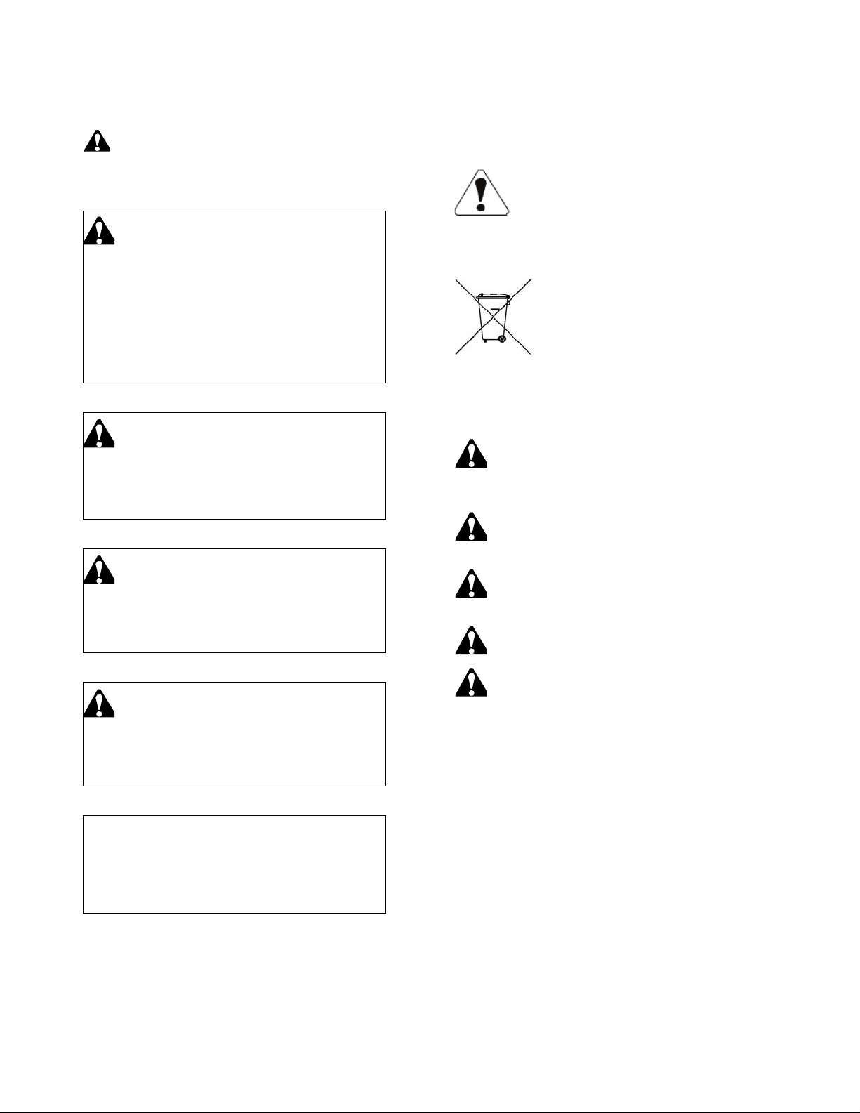
SAFETY
to alert you to potential personal injury
which, if not avoided, will result in death or
Indicates a potentially hazardous situation
which, if not avoided, could result in death or
Indicates a potentially hazardous situation,
if not avoided, may result in minor or
CAUTION
a potentially hazardous situation, which, if not
Read all safety information prior to installation
of the Silent Storm Pumping System.
SAFETY INSTRUCTIONS
SAFETY INSTRUCTION
This is a SAFETY ALERT SYMBOL. It is used
All operating instructions must be
read, understood, and followed by
the operating personnel. Flowtronex
accepts no liability for damages or
operating disorder which are the
result of non compliance with the
operating instructions.
hazards. Obey all safety messages that follow
this symbol to avoid possible injury, death!
FAILURE TO FOLLOW THE INSTRUCTIONS
MAY RESULT IN A SAFETY HAZARD.
DANGER
Indicates a potentially hazardous situation
serious injury.
WARNING
serious injury.
CAUTION
which
moderate injury.
When the Pumping System
components reach the end of life
the components should be
disposed of or recycled in
accordance with local laws.
SAFETY REMINDERS
1. This manual is intended to assist in
the installation, operation, and repair
of the system and must be kept with
the system.
2. Installation and maintenance MUST
be performed by properly trained and
qualified personnel.
3. Review all instructions and warnings
prior to performing any work on the
system.
4. Any safety decals MUST be left on
the controller and pump.
5. The system MUST be disconnected
from the main power supply before
attempting any operation or
maintenance on the electrical or
mechanical part of the system.
Failure to disconnect electrical power
before attempting any operation or
maintenance can result in electrical
shock, burns, or death.
Used without the safety alert symbol indicates
avoided, may result in property damage.
Page 6

4
ADDITIONAL SAFETY INFORMATION
This pump has been designed for safe and reliable
operation. A pump is a pressure-containing device
with rotating parts that could be hazardous.
Operators and maintenance personnel must
realize this and follow necessary safety measures.
Proper safety procedures must be followed. Xylem
Flowtronex shall not be liable for damage or
delays caused by a failure to observe the
instructions in this manual.
Safety Apparel:
• Wear insulated work gloves when
handling hot bearings or using bearing
heater.
• Wear heavy work gloves when handling
parts with sharp edges, especially
impellers.
• Wear safety glasses (with side shields) for
eye protection, especially in machine shop
areas.
• Wear steel-toed shoes for foot protection
when handling parts, heavy tools, etc.
• Wear other personal protective equipment
to protect against hazardous/toxic fluids.
Coupling Guards:
• Never operate a pump without a coupling
guard properly installed.
• Never force piping to make a connection
with a pump.
• Use only fasteners of the proper size and
material.
• Ensure there are no missing fasteners.
• Beware of corroded or loose fasteners.
Operation:
• Do not operate below minimum rated flow,
or with suction/discharge valves closed.
• Do not open vent or drain valves, or
remove plugs while system is pressurized.
Maintenance Safety:
• Always lock out power.
• Ensure power is isolated from system and
pressure is relieved before disassembling
pump, removing plugs, or disconnecting
piping.
• Use proper lifting and supporting
equipment to prevent serious injury.
• Observe proper decontamination
procedures.
• Know and follow company safety
regulations.
• Never apply heat to remove impeller.
• Observe all cautions and warnings
highlighted in pump instruction manual.
Page 7
5
GENERAL DESCRIPTION
PRODUCT DESCRIPTION
A Flowtronex Silent Storm Variable Speed
Pumping System is custom built to the
requirements provided by the purchaser. The
Silent Storm pumping system is a modular
variable speed system designed to maintain a
constant discharge pressure while providing a
variable flow rate to match the water demand of
the system. The system minimizes power
consumption by combining a variable speed lead
pump with constant speed lag pumps. The Silent
Storm utilizes a microprocessor-based controller
to efficiently manage pump operation to match a
wide range of pressure boosting applications.
Silent Storm Variable Speed Pumping Systems
are self-contained, pre-assembled and factorytested pumping plants. Silent Storm utilizes state
of the art technology, yet employs a simplistic and
straightforward design that makes installation,
operation, and maintenance an easy task, even for
the most inexperienced of operators.
This manual serves as a guide to understanding
the features of Silent Storm Pumping Systems and
provides a quick and clear reference for answers
to most questions pertaining to its service. Every
attempt has been made to explain all facets of
system operation and maintenance. However,
should you have specific questions not addressed
in this manual, you are encouraged to contact your
nearest Flowtronex Authorized FlowNet
representative, or the factory (800-786-7480
Ext. 3).
OPERATIONAL LIMITS
See pumping system nameplate information for
pumping system flow capacity, pressure, full load
current and electrical ratings.
Unless special provisions have been made for
your pumping systems, the system pressure rating
is as follows:
Pump system type
Max discharge pressure
End suction centrifugal
175 psi
Vertical turbine
200 psi
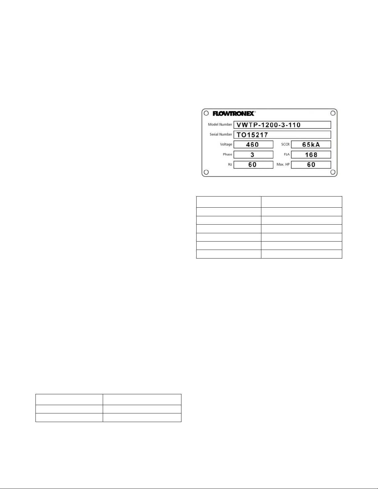
NAMEPLATE INFORMATION
The system nameplate gives identification and
rating information as identified in the figure below.
Figure 1: Sample Nameplate
Field
Explanation
Voltage
Required input voltage
SCCR
Short circuit current rating
Phase
Number of motor phases
FLA
Full load amps
Hz
Required frequency (hertz)
Max. HP
Maximum horsepower
Permanent records for this system are referenced
by the serial number. Include the serial number
with all correspondence and spare parts orders.
STATION NUMBERING
Example: V W T P - 900 - 3 - 120
1. Control Type:
V = VFD
2. Water Source Type:
W = Wet Well
V = Vessel
C = Can
F = Flooded
L = Lift
B = Boost
D = Deep Well
Page 8
6
S = Submerged Sled pump assembly
M = Floating pump assembly
3. Pump Type:
C = Horizontal
S = Submersible
T = Vertical Turbine
M = Multi-stage Horizontal (ex. Goulds
SSV)
E = Submersible Trash Pump (ex. Ebara)
4. System Type:
P = Pump Station
T = Transfer
X = Control Package
5. System Gallons per Minute: If a multi-zone
system, show all zones with a slash ( / )
between each. If it is a control package,
show the total number of pumps to be
controlled.
6. Quantity of Pumps: Include pressure
maintenance pump and current pumps do not include future pumps in model
number.
7. System Pounds per Square Inch: If multizone system, show all zones with a slash
( / ) between each zone. Design must
assume that all zones run at the same
time. Describe in no-uncertain terms the
performance of each zone. If the station
has spacing for future pumps, always
create a model number showing the
current conditions service. Make notes in
your documentation describing the
"current" versus "future" conditions of
service. On boosted systems, model
number should reflect the differential
pressure with notes describing the
incoming pressure.
HANDLING
Qualified personnel should unload and handle the
unit. Prevent damage due to dropping or jolting
when moving the unit. Thoroughly inspect the unit
for damage upon receipt. Immediately notify the
carrier of transportation damage. Ensure that
sensing lines are free of crimps and kinks.
The unit is top heavy due to the position of the
equipment. Do not use component eyebolts to lift
the pump station.
WARNING: Falling Objects Hazard
Eyebolts, if provided, are designed to lift only the
components to which they are attached.
Failure to follow these instructions could result in
serious personal injury, death, and/or property
damage.
STORAGE
During periods of storage, the unit should be
covered to prevent corrosion and contamination
from dirt. Store the unit in a clean, dry location to
prevent condensation and freezing. After storage,
check that it is dry before applying power. Specific
component storage instructions must be followed
in accordance with the respective equipment
manufacturer's recommendations.
CAUTION: Extreme Temperature Hazard
Extreme temperatures are to be avoided. (Below
32ºF and above 110ºF.)
Failure to follow these instructions could result in
serious property damage and/or moderate
personal injury.
FIELD CONNECTION DIAGRAMS
Actual equipment manufacturers/models installed
are system specific. Refer to specific
manufacturers’ Installation, Operation &
Maintenance Manuals for details unique to each
component. The pump instruction manual is
supplied with the system (if applicable).
Review the wiring diagrams and dimensional
drawings prior to unit installation and operation.
NOTE: Electrical supply must match the control
panel nameplate specification. Incorrect voltage
can cause fire, damaging electrical components
and void the warranty.
NOTE: Electrical supply must be installed by a
qualified electrician in accordance with all
applicable codes, ordinances, and good practice.
Page 9
7
GROUND CONNECTIONS
A grounding terminal is provided for a dedicated
ground wire connection. All provisions of the
National Electrical Code and local codes must be
followed.
WARNING: Electrical Shock Hazard
Conduit grounds are not adequate. A separate
ground wire must be attached to the ground lug
provided in the enclosure to avoid potential safety
hazards.
Failure to follow these instructions could result in
serious personal injury, death, or property
damage.
Page 10
8
INSTALLATION
LOCATION
Locate the pumping system in a clean, well
ventilated, and properly drained location. It is
recommended that the location selected facilitates
ease of inspection, maintenance, and service.
Outside installation requires protection from
freezing.
WARNING: Falling Objects Hazard - Heavy
Load, May Drop If Not Lifted Properly.
Do not lift the entire unit by component eyebolts.
Eyebolts on components are used for factory
assembly only and are not intended to lift the
complete package.
Failure to follow these instructions could result in
serious personal injury, death, or property
damage.
FOUNDATION
With proper installation and a suitable foundation,
this unit is built to supply years of service.
Establish a base of concrete weighing a minimum
of 2-1/2 times the weight of the unit. (Check the
shipping tickets or the pumping system drawing for
unit weight.) Tie the concrete pad in with the
finished floor. Use the appropriate anchor bolts to
secure the pumping system to the foundation.
Pump packages with electrical conduit below
surface may require corrosion protection approved
for this condition.
WARNING: Electrical Shock Hazard
Electrical conduit installed below the surface may
require a corrosion resistant protective coating to
prevent conduit corrosion and electrical shock.
Failure to follow these instructions could result in
serious personal injury, death, or property
damage.
Place the unit on its concrete foundation,
supporting it with steel wedges or shims. These
wedges or shims should be put on both sides of
each anchor-bolt and midway between the bolts,
to provide a means of leveling the base.
After the pumping system has been leveled, install
the correct number of anchor bolts and tighten to
secure the system.
PUMP INSTALLATION
In most cases, if the pumps have an overall length
of less than twenty (20) feet, they are shipped
assembled. Only the motor, head shaft, strainer
basket, and discharge connection are shipped
separately. The following instructions describe
installation for assembled pump stations.
Prior to Installation
1. Measure each pump and document on the
set/start report.
2. Confirm wet well probe measurements.
Measure the distance from the bottom of
the wet well to the top of the skid to
ensure that pumps were ordered with the
correct length. Preferred length is 12
inches above the bottom of the wet well.
3. Tighten all bolts and couplings on the
pump before proceeding.
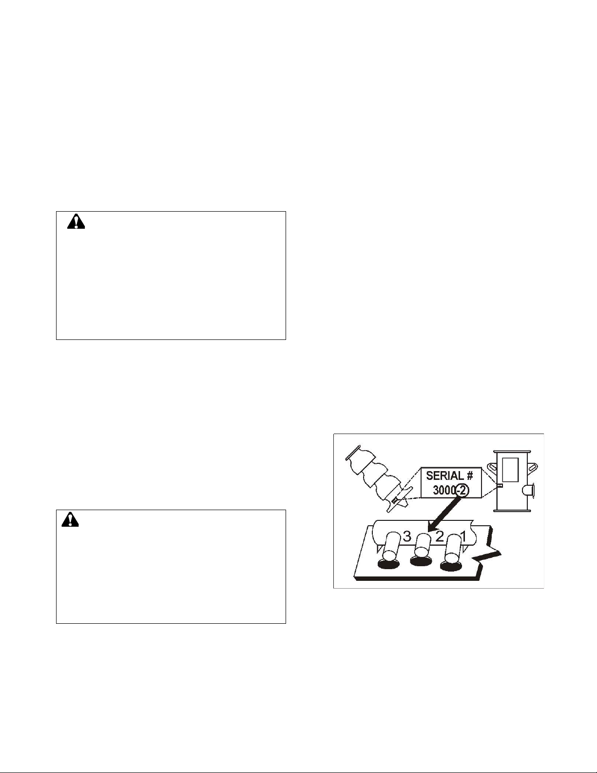
4. Install each pump according to the last
digit on the pump identification tag.
Figure 2: Location of Serial Number and
Skid Position
Installing Assembled Pump Station
1. To set pump, use a crane or other
adequate lifting device and a cable sling of
adequate length. Attach the cable to the
lifting lugs (lifting eyes) on either side of
the pump.
Page 11
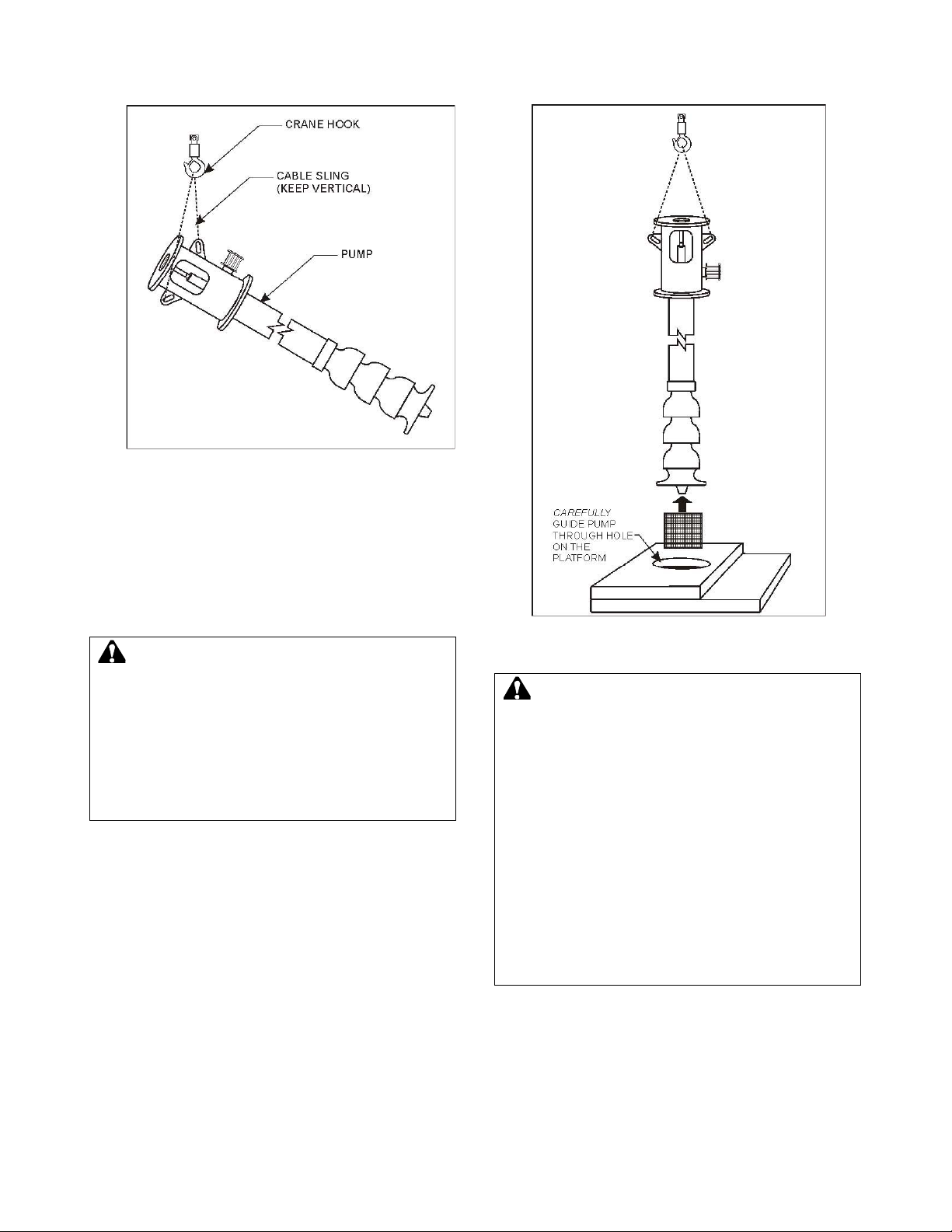
9
Figure 3: Lifting Pump
2. After the cable-sling is attached to the
lifting lugs (lifting eyes) on the pump head,
raise the pump to a vertical position. While
in this position, install the strainer basket
with bolts and clips. Position the pump
over its access hole on the skid.
WARNING: Falling Objects Hazard
DO NOT work under heavy suspended object
unless there is positive support and safeguards
should a hoist or sling fail.
Failure to follow these instructions could result in
serious personal injury, death, or property
damage.
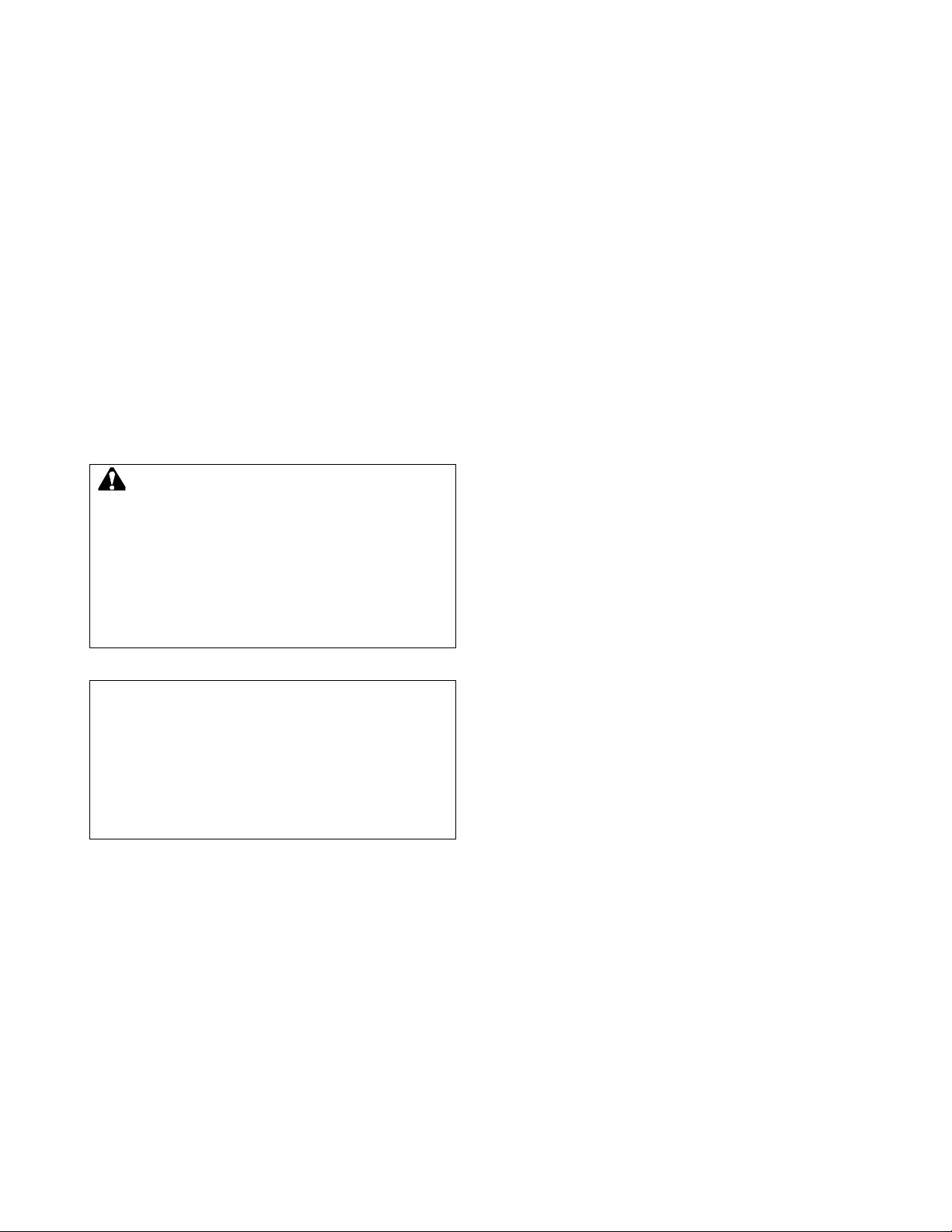
3. Very slowly, lower the pump through its
access, keeping one hand on the pump to
detect any bumping by the pump against
the edge of its hole or the wall of the wet
well. When the pump is properly installed,
it should not touch the side of the wet well.
Premature bearing failure or destruction of
the bowl assembly can result from
improper installation.
Figure 4: Position Head Over Access
Hole on Skid
WARNING: Equipment Damage Hazard
Be prepared to stop lowering the pump
IMMEDIATELY if any bump is felt.
It is possible that the pump bowl could catch on
the edge of the skid and become unhooked from
the cable or other lifting device. Possible serious
bodily injury or damage to the pump could result.
Verify and ensure that the safety latch on the hook
works properly.
Failure to follow these instructions could result in
serious personal injury, death, or property
damage.
4. Push the pump slightly off-center when it
is being lowered in the wet well to avoid
hitting the manifold discharge pipe.
5. Stop lowering the pump when the base of
the head is approximately 1/8 to 1/4 inch
above the platform.
Page 12
10
6. Line up the spool with the pump isolation
valve on the manifold-discharge pipe and
set the pump on the skid. Start threading
the base bolts on the pump head. Slide
the Victaulic clamp gasket so that the
clamp rides in the gloves on both the
isolation valve and the spool. Tighten the
Victaulic clamp. Tighten the base bolts.
7. If the pumps are shipped unassembled,
refer to the Gould Pumps, Model VIT
Installation, Operation, & Maintenance
Instructions.
8. Install the vertical hollow shaft motor to
the top of the pump’s disconnected head.
Refer to the Gould Pumps, Model VIT
Installation, Operation, & Maintenance
Instructions.
WARNING: Falling Objects Hazard
DO NOT work under heavy suspended object
unless there is positive support and safeguards
should a hoist or sling fail.
Failure to follow these instructions could result in
serious personal injury, death, or property
damage.
CAUTION: Motor Rotation Hazard
DO NOT install motor shaft, Gib key, or adjusting
nut until motor rotation has been verified.
Failure to follow these instructions indicates a
potentially hazardous situation, which, if not
avoided, may result in property damage.
Page 13

11
STATION OPERATION
This section covers the sequence of operation for
your station including: Door Switch Operation,
Automatic Operation, and System Safeties.
DOOR SWITCH OPERATION
System Control Switch
Allows operator to select how the station
operates:
OFF Regardless of individual switch
position, pumps do not operate.
AUTO Places the system in
automatic mode.
MANUAL Places the pumps in manual
mode. The operator must start and stop
the individual pumps using each pump’s
switch.
Individual Pump Switches
Allows operator to select which pumps
operate:
NOTE: Pumps have an OFF/ON switch or
a MANUAL/OFF/AUTO switch.
MANUAL These switches start the
individual pumps. However, the system
MANUAL/OFF/AUTO switch must be
placed in the MANUAL position before the
individual pump is turned ON. Otherwise,
each switch must be cycled OFF, then ON
to “arm” the pump for operation.
OFF Selected pump does not operate,
regardless of any other switch position.
AUTO Selected pump operates in
Automatic Mode provided there is not an
individual pump overload trip.
ON Selected pump will operate
immediately if the system switch is set to
MANUAL, and there are no faults. In
AUTO, the pump will come on if there is a
demand for it, and the PLC calls for it.
VFD / Bypass Switch
Enables or disables the VFD:
VFD This switch position enables VFD
operation in either automatic or manual
mode depending on the position of the
system switch. VFD is the normal position
of the switch.
BYPASS This switch position, places the
pump station in either "Automatic VFD
Bypass" or "Manual VFD Bypass" mode of
operation depending on the position of the
MANUAL/OFF/AUTO switch. In this mode,
the pumps will start "across the line."
This mode is intended for use only when
the VFD is not functional. Turn all pump
switches to OFF before placing the
system in BYPASS mode.
VFD Selector Switch (Optional On Some
Stations) – PUMP 1 / PUMP 2 / PUMP 3
This switch determines which pump runs on
the VFD when switch is in the MANUAL mode.
However, if this switch is not present, the first
pump with VFD capability runs as the VFD
pump.
When the switch is in AUTO, the pump
selected to run on the VFD has the lowest
accumulated run time. Only one pump at a
time can run on the VFD (also known as an
inverter). Once a pump is running on the
inverter, this switch is disabled. If another
pump is selected when the inverter is in use,
the newly selected pump does not run.
Low Discharge/Differential Pressure
Switch
This switch allows the operator to enable or
disable either the "Low Discharge Pressure"
shut-down circuit, or the filter differential
pressure circuit. Only one circuit can be
overridden at one time, therefore a three-way
switch is used.
LDP OVERRIDE This position prevents a
low-discharge pressure fault from shutting
down the pump station. Use the LPD
OVERRIDE position during the initial pipe
filling and when restarting the system from
a de-pressurized condition in MANUAL or
AUTO mode.
Page 14

12
ACTIVE PRESSURE OVERRIDE
This activates both the "low discharge
pressure" and "filter differential pressure"
protection systems. Normally, the pump
station should be left in this position during
automatic operation to prevent
overloading the pump motors and avoid
damaging erosion in the event of a major
pipe break.
DIFFERENTIAL PRESSURE OVERRIDE
This switch position allows overriding the
filter differential pressure switch. This
override should be used only temporarily,
and is not intended for prolonged
operation.
Wye Strainer or Filter Switch
If present on the station, this switch controls
the operation of the Wye strainer or filter
solenoid.
OFF Prevents the Wye strainer or filter
from flushing.
MANUAL The Wye strainer or filter
flushes continuously, regardless of other
switch settings. The MANUAL position
may be used for de-pressurization for
maintenance, or when attempting to clean
a seriously dirty screen.
AUTO In this position, the Wye strainer or
filter flushes for 10 to 15 seconds, 60
seconds after the main VSP, or the first
XL (across-the-line) pump, starts.
Afterwards, flushing occurs for 10 to 15
seconds after each hour of continuous
pump operation. This is the normal
position for the switch.
Lake Screen Switch
If present on the station, this switch controls
the operation of the solenoid valve, which
operates the self-rotating lake inlet screen.
OFF Prevents the Lake Screen from
working.
MANUAL Energizes the solenoid
continuously regardless of the status of
the station. This can be used to depressurize the system, or to verify
operation of the screen during
maintenance.
AUTO Causes the Lake Screen solenoid
to open after the main VSP has been
operating at least one minute, the
minimum flow requirement is met, and the
speed test is not trying to stop the VSP.
This is the normal position of this switch.
Well Pump Switch
If present on the station, this switch allows
the operator to control the operation of a well
pump. In most cases, the operation of this
pump is completely independent of the
operation of the pump station. However, the
system is configurable so that the well pump
does not run during the lockout period.
OFF Prevents the well pump from
running.
MANUAL The well pump runs
continuously until the switch is turned
OFF.
AUTO The well pump starts and stops
based on a separate level switch.
Reset Push Button
This button allows the operator to clear
(Reset) any faults within the system once the
cause of the fault has been cleared. It is also
used for the lamp test.
RESETTING FAULTS Faults must be
reset by the reset button, unless the fault
automatically resets as described in the
System Safeties section. Pressing the
reset button clears all fault counters.
These counters prevent certain faults from
automatically resetting indefinitely. If the
fault lamp does not go out after resetting,
the cause of the fault is still present and
must be resolved before normal operation
can continue.
LAMP TEST Pressing this button for five
seconds causes all lamps on the front
panel to illuminate. Replace any lamps
that do not illuminate. For safety reasons,
the lamp test needs to be performed on a
regular basis.
Page 15

13
AUTOMATIC OPERATION
Overview
The primary benefit of Variable Speed
Pumping (VSP) Systems is to ensure surgefree starts and stops while maintaining a
constant down-stream line pressure with no
mechanical pressure-regulating valve. This
minimizes pipeline failures due to surges and,
not incidentally, reduces the utility bill for the
station.
Automatic operation is selected by the system
control switch. In automatic operation, all
pump activity is determined by the PLC. The
position of the individual pump switch lets the
PLC know whether or not it is available to run.
In most cases, all pump switches are in the
ON position. When a pump or a motor is
removed from the system, turn the pump
switch OFF, and the PLC will not try to run
that pump.
The PLC brings one pump on at a time in
order to satisfy the start criteria (usually
setpoint pressure). Some stations are
designed to start and stop the pumps based
on remote start signals, level probe signals, or
other criteria. The standard start and stop
sequence is as follows:
Pressure below setpoint to start
Combo 1
5 PSI
Delay time to start Combo 1
0 SEC
Pressure above setpoint to stop
Combo 1
5 PSI
Delay time to stop Combo 1
5 SEC
Pressure below setpoint to start
Combo 2
10 PSI
Delay time to start Combo 2
0 SEC
Pressure above setpoint to stop
Combo 2+
30 PSI
Delay time to stop Combo 2+
90 SEC
Pressure below setpoint to start
Combo 3+
5 PSI
Delay time to start Combo 3+
10 SEC
NOTE: The criteria for Combo 4 and above
are the same as Combo 3.
The "pressure above setpoint to stop" and
"delay time to stop" parameters only apply to
Combo 1. The values of 30 PSI and 90
seconds were intentionally selected since they
are out of range and will never be used.
There are three (3) main types of auto
operation – line fill, system charging, and
normal operation.
Line Fill Mode
Line Fill Mode is used when downstream
pressure is significantly below setpoint, such
as during the initial startup, or when leaks in
the lines are repaired. Operation is as follows
(performed in order):
System control switch: OFF
All Individual Pump switches: ON
Override/Active switch: LDP Override
(Low Discharge Pressure fault disabled)
VFD Bypass switch: VFD
System control switch: AUTO
As soon as the system control switch is turned
to the AUTO position, the VSP (Variable
Speed Pump) with the lowest run time starts
at a reduced speed. When the VSP starts, the
startup ramp in the program lowers the
setpoint to 2 PSI above the actual
downstream pressure. The VFD adjusts the
speed of the VSP to reach the desired
setpoint. The setpoint ramps up at the rate of
1 PSI every 4 seconds until the normal
setpoint is reached.
This feature prevents the VSP from coming up
to full speed too quickly, and prevents the lag
pump(s) from starting prematurely. This rampup feature allows the system to develop a
controlled and smooth start up from a
completely de-pressurized condition,
minimizing pipe breakage from water hammer.
Once the pressure above setpoint value is
reached, the VSP shuts down. The pump
switches can be left in ON and the system
control switch left in AUTO. The
Override/Active switch should be returned to
the ACTIVE position. The station is now in
system "charging" mode.
System Charging Mode
If there are no heads open, and the pressure
is within the defined range of operation,
pressure may slowly drop due to system
Page 16

14
leakage, or other small demands. A PM pump
is provided to address this issue. Most
stations, but not all, include a PM pump. Door
switches are set as follows (from end of line fill
mode):
System control switch: AUTO
All Individual Pumps switches: ON
Override/Active switch: ACTIVE (Low
Discharge Pressure and differential
pressure faults enabled)
VFD Bypass switch: VFD
NOTE: As downstream pressure drops to
more than 5 PSI below setpoint, the PM pump
starts up. It runs until the system pressure
builds up to 5 PSI above setpoint, and then
shuts off.
Two issues can come into play here. One is
cycle time. This refers to the number of times
an hour that the PM pump starts and stops
(one cycle). If the amount of cycles is
excessive, either the system leaks have to be
repaired, or the start/stop parameters need to
be tuned (normally by dropping the pressure
below setpoint to start, or increasing the
pressure above setpoint to stop). Must-run
times can cause the opposite problem. The
PLC determines the must-run time for each
pump. If this value is set too high, the PM
pump reaches its "pressure above setpoint"
and stops before the must-run time setting
indicates. This can lead to an overpressurization situation. Address this problem
by lowering the must-run time.
WARNING: Excessive Run Time Hazard
Excessive must-run times, stop times, or stop
pressure setting can cause system overpressurization, pipe damage, and potentially
cause personal injury. Consult your service
technician or the factory if you are unsure about
any settings.
Failure to follow these instructions could result in
serious personal injury, death, or property
damage.
Normal Operation
Normal Operation occurs when heads are
turned on, or a demand for water exists. Door
switches are set as follows (from end of line fill
mode):
System control switch: AUTO
Pump 1 switch: ON
Pump 2 switch: ON
Pump 3 switch: ON
PM Pump switch: ON
Override/Active switch: ACTIVE (Low
Discharge Pressure and differential
pressure faults enabled)
VFD Bypass switch: VFD
When the pressure drops 5 PSI below
setpoint, the PM pump starts and continues to
run until the pressure is 5 PSI above the
setpoint. When this pressure is reached, the
PM pump turns OFF. If the pressure continues
to drop to 10 PSI below setpoint, the VSP
starts. Five seconds later, the PM pump turns
OFF. This is the operation sequence for
Combo 1.
When the VSP starts, the startup ramp in the
program lowers the setpoint to 2 PSI above
the actual line pressure. The VFD adjusts the
speed of the VSP to maintain the discharge or
downstream pressure at the setpoint. The
setpoint ramps up at the rate of 1 PSI every 4
seconds until the normal setpoint is reached.
As the setpoint rises, so does the speed of the
VSP. This feature prevents the VSP from
coming up to full speed too quickly and
prevents the lag pump(s) from starting
prematurely. This ramp-up feature allows the
system to develop a controlled and smooth
startup from a completely de-pressurized
condition, minimizing pipe breakage from
water hammer. This is the operation sequence
for Combo 2.
If the VFD reaches full speed driving the main
VSP and the discharge pressure is more than
10 PSI below the setpoint, the demand for
water is greater than the capacity of the VSP.
An XL (across-the-line) pump starts as the lag
pump. This operation sequence occurs during
Combo 3.
When an XL pump starts, and the VFD is
driving another pump, the inverter (VFD)
speed immediately ramps down to the inverter
“speed when lag pump starts” setting. This
permits the XL pump to start with very little
pressure surge, or related water hammer.
Once the lag pump is at full speed, the VSP
ramps back up to try and maintain setpoint
pressure.
Page 17

15
If the demand for water is still greater than the
capacity of these two pumps, then Combo 4
starts. As occurred in the previous Combo, the
inverter (VFD) speed immediately ramps down
to the “speed when lag pump starts” setting.
The second lag pump starts up and goes to
full speed, and the VSP ramps back up to try
and maintain setpoint pressure.
This sequence of events repeats for all
available Combos.
When the flow decreases, the VFD (inverter)
slows down to maintain a constant discharge
pressure. Eventually as the speed decreases,
a setpoint is reached where the VSP is not
pumping any water. The XL pump(s) are
supplying all the water required. If the flow
continues to decrease, the discharge pressure
increases above the setpoint. Slowing the
VFD (inverter) does not reduce the pressure
because the VSP is not currently pumping any
water. Once the pressure reaches 1 or 2 PSI
above the setpoint pressure, the Overpressure
Accumulator starts counting. Once the count
reaches 750, the last XL pump is stopped. If
the pressure is well above the setpoint, or
increasing rapidly, the pump can stop quickly;
in 1 to 2 seconds. If the pressure remains 1 or
2 PSI above setpoint, the pump turns OFF in
approximately 20 seconds. When an XL
pump stops, the inverter (VFD) speed
immediately ramps up to the “speed when lag
pump stops” setting. This prevents the system
pressure from dropping excessively due to the
XL pump shutting off.
Once an XL pump has been stopped, the VSP
waits for the time entered in the "delay time to
start" before the XL pump is permitted by the
program to restart. This feature minimizes
pump cycling and pressure surges. The
generic value for Combo 3 and up is 10
seconds. If the conditions for starting an XL
pump are met after this waiting period,
normally 10 seconds, the pump is restarted.
If the flow continues to decrease, each XL
pump is stopped in the manner described
above, until only the VSP is running. Stopping
the last VSP is accomplished by using "Speed
Test," which uses a stop method different from
stopping an XL pump. Because the inverter
speed keeps lowering as the flow decreases,
the discharge pressure would never get above
the setpoint. In this situation, the VSP would
"idle," pump no water, and would never turn
off. To shut down the VSP, the system
initiates the "Speed Test" whenever the flow is
below a predetermined value for 15 seconds.
The program then lowers the setpoint by 5
PSI. If the VFD speed falls below a
predetermined value and the pressure
remains above the reduced setpoint for 15
seconds, the VSP turns OFF, and the setpoint
returns to normal. Speed Test returns the
station to "System Charging" mode until a new
demand for water is created.
Page 18

16
Manual VFD Operation
Overview
Manual operation is selected by the system
control switch. In manual operation, all pump
activity is controlled by the individual pump
switches. In the case of multiple pumps
available for VFD operation, the VFD select
switch determines which pump(s) run in VFD
mode. However, some stations do not come
equipped with a VFD select switch. In that
case, the first pump that is started is always
the VFD pump. The speed of the VFD pump is
controlled by the speed potentiometer (speed
pot). All other pumps run in XL mode (at full
speed). The Override/Active switch enables or
disables the low-discharge pressure fault.
NOTE: Manual operation is rarely used.
However, it does allow for operation of
individual pumps for testing purposes.
Sequence of Operation (performed in
order)
System control switch: OFF
All Individual Pump switches: OFF
Override/Active switch: LDP Override
(Low Discharge Pressure fault disabled). If
initial system pressure is high enough,
place in Active.
VFD Bypass switch: VFD
VFD Select switch: Pump 1
Speed Potentiometer: Turned 100%
counter-clockwise (0 speed)
System control switch: MANUAL
Pump 1 switch: ON
Speed Potentiometer: Turn clockwise to
increase speed of pump 1
Pump 2 switch: ON (if required)
Speed Potentiometer: Adjust speed as
required to maintain set point pressure.
Pump 3 switch: ON (if required)
Speed Potentiometer: Adjust speed as
required to maintain set point pressure.
NOTE: When done, turn OFF all pump
switches and place system control switch in
OFF. Return Override/Active switch to
ACTIVE. If the station can be run in Automatic
mode, return the system switch to AUTO and
turn ON all pump switches.
VFD Bypass Operation, Manual mode
Overview
This is an abnormal operating mode and
would only be used when the VFD (inverter) is
not operable but there is a need to irrigate. If
the PLC is operable, and PRV (Pressure
Reducing Valve) is in the system and
functioning, we strongly recommend using
Automatic VFD Bypass Mode.
WARNING: Manual VFD Bypass Hazard
This mode of operation should be used as a last
resort if there is no DSR, or it is not functioning
correctly. Constant operator attendance is
recommended when this mode is used. The water
demand must be calculated to match the
individual pump output as closely as possible.
Failure to do so will cause a serious over-pressure
condition.
Failure to follow these instructions could result in
serious personal injury, death, or property
damage.
System Operation (performed in order)
System control switch: OFF
All Individual Pump switches: OFF
Override/Active switch: LDP Override
(Low Discharge Pressure fault disabled). If
initial system pressure is high enough,
place in ACTIVE.
VFD Bypass switch: BYPASS
VFD Select switch: Pump 1
Speed Potentiometer: N/A
System control switch: MANUAL
Pump 1 switch: ON
Allow system pressure to stabilize before
turning on additional pumps.
Pump 2 switch: ON (if required)
Pump 3 switch: ON (if required)
Page 19

17
NOTE: When done, turn OFF all pump
switches and place system control switch in
OFF. Return Override/Active switch to
ACTIVE.
VFD Bypass Operation, Auto mode
Overview
VFD Bypass mode is an EMERGENCY ONLY
mode used when the VFD is inoperative.
Monitor station operation closely when in
bypass mode due to limited pressure control
available. Your station must be equipped with
a PRV (Pressure Reducing Valve) in order to
run VFD Bypass Mode automatically. This
valve now assumes the pressure regulating
function that was performed by the VFD in
normal operation. Ensure that the PRV is
adjusted to maintain your downstream
pressure at no more than 12 PSI above
setpoint pressure. Verify that the PRV is
operating correctly before leaving the station
unattended. Check station regularly to ensure
continued proper operation. If your station is
not equipped with a PRV, do not operate in
automatic VFD bypass mode.
WARNING: VFD Bypass Switch Hazard
This mode of operation should be used as a last
resort if there is no DSR, or it is not functioning
correctly. Constant operator attendance is
recommended when this mode is used. The water
demand must be calculated to match the
individual pump output as closely as possible.
Failure to do so will cause a serious over-pressure
condition.
Failure to follow these instructions could result in
serious personal injury, death, or property
damage.
VFD Bypass mode is selected by the VFD /
Bypass switch. The system control switch
MUST be turned to the OFF position before
selecting VFD bypass mode. Operation is
similar to normal automatic operation but the
start / stop sequences differ greatly. The
registers below regulate this.
NOTE: These are generic values and might
differ from your station.
Pressure below setpoint to start
Combo 1
5 PSI
Delay time to start Combo 1
0 SEC
Pressure above setpoint to stop
Combo 1
5 PSI
Delay time to stop Combo 1
5 SEC
Pressure below setpoint to start
Combo 2
12 PSI
Delay time to start Combo 2
3 SEC
Pressure above setpoint to stop
Combo 2
1 PSI
Delay time to stop Combo 2
60 SEC
Pressure below setpoint to start
Combo 3
15 PSI
Delay time to start Combo 3
10 SEC
Pressure above setpoint to stop
Combo 3
1 PSI
Delay time to stop Combo 3
30 SEC
Flow setpoint to stop Combo 1
0 GPM
Flow setpoint to stop Combo 2
20 GPM
Flow setpoint to stop Combo 3
80% *
Flow setpoint to stop Combo 4
80% **
80% of the previous combo’s maximum
output. * If one main pump puts out 500 gpm,
you would enter 400 gpm here. ** If two main
pumps put out 1000 gpm, you would enter 800
gpm here.
Other significant differences between VFD
Bypass and Automatic VFD Operation are as
follows:
1. The overpressure accumulator is not used
in VFD bypass mode.
2. Flow will dominate stopping main pumps
due to low Combo stop pressure settings.
The PM pump will continue to operate
similarly to VFD mode.
3. VFD Fault and Maximum RPM signals are
ignored.
4. Pump starts are caused by pressure drop
as in VFD mode, but due to operational
differences, the settings are modified from
those used in VFD mode.
Sequence of Operation (performed in
order)
System control switch: OFF
All Individual Pump switches: ON
Page 20

18
Override/Active switch: LDP Override
(Low Discharge Pressure fault disabled). If
initial system pressure is high enough,
place in Active.
VFD Bypass switch: Bypass
VFD Select switch: N/A
Speed Potentiometer: N/A
System control switch: AUTO
When done, place system control switch in
OFF. Return Override/Active switch to
ACTIVE.
The PM pump continues to charge the system
as in Automatic operation. Start and stop
sequence is based on pressure.
Once a demand for water exists, the PLC
starts the main pump with the lowest run time
as an XL (across- the-line) pump, based on
the “pressure below setpoint." If the flow
capacity of the main pump exceeds the
demand for water, pressure increases until the
PRV opens and discharges the excess flow
back into the water source. As demand for
water increases, the PRV closes. If the PRV is
completely closed, and the “pressure below
setpoint" drops low enough, the PLC brings on
the next Combo as required (all in XL mode).
The lead pump remains at full speed while the
next pump also comes up to full speed. If the
cumulative flow capacity of the main pumps in
operation exceeds the demand for water, the
PRV opens and discharges the excess flow
back into the water source. This process is
repeated for all available Combos.
Combo shutdown based on flow is made
possible by the way flow is read. The location
of the flow meter measures only the flow that
is actually being used. The flow out of the
PRV discharge that is returned into the water
source does not count as "measured flow."
The result is as demand for water decreases,
pressure continues to rise. The PRV opens as
required to maintain pressure. As more flow is
going out the PRV discharge, less flow is
actually being used. When the flow reading
drops below the “flow setpoint to stop” value,
the pumps shut down in the reverse order that
they started. Based on the demand for water,
this process continues until all main pumps
have shut down, and the station returns to
"System Charging" mode.
PLC Bypass Operation
Overview
This is an abnormal operating mode and
would be used if the PLC was not operable
and there is need to irrigate.
WARNING: PLC Bypass Hazard
This mode of operation should be used as a last
resort if there is no DSR, or it is not functioning
correctly. Constant operator attendance is
recommended when this mode is used. The water
demand must be calculated to match the
individual pump output as closely as possible.
Failure to do so will cause a serious over-pressure
condition. The high pressure discharge safety
does not function in PLC bypass, and damage to
your piping could occur. The only safeties that
function in PLC bypass are low discharge
pressure and phase fault.
Failure to follow these instructions could result in
serious personal injury, death, or property
damage.
System Operation (performed in order)
System control switch: OFF
All Individual Pump switches: OFF
Override: LDP Override (Low Discharge
Pressure fault disabled). If initial system
pressure is high enough, place in Active
VFD Bypass switch: NA
VFD Select switch: NA
Speed Potentiometer: N/A
PLC Bypass switch: BYPASS
System control switch: MANUAL
Pump 1 switch: ON
Allow system pressure to stabilize before
turning on additional pumps.
Pump 2 switch: ON (if required)
Pump 3 switch: ON (if required)
NOTE: When done, turn OFF all pump
switches and place system control switch
in OFF. Return Override/Active switch to
ACTIVE.
Page 21

19
SYSTEM SAFETIES
Overview
The program in the PLC protects the system
by shutting down in either of the “Auto” or
“Manual” Modes of operation if it detects any
of the following problems:
Alarm or Fault
Automatic Restart?
Low Discharge
Pressure
No Automatic Restart
High Discharge
Pressure
Automatic Restart
Low Inlet Pressure
(Optional)
Automatic Restart
Loss of Prime
(Optional)
Automatic Restart
Low Level (Optional)
Automatic Restart
Station Phase
Pressure (Optional)
No Automatic Restart
Individual Pump
Faults
No Automatic Restart
VFD Fault
Automatic Restart
Table 1: Automatic Restart After Alarm
or Fault
Automatic Mode of Operation
"High Discharge Pressure," “Station Phase
Failure," "Low Inlet Pressure," "Low Level,"
"Loss of Prime," and "VFD Fault" allow the
system to restart automatically when the fault
clears in the automatic mode of operation. The
PLC allows three (3) automatic restarts (which
can be caused by any combination of these
faults) in a one-hour period. At the fourth
occurrence in a one-hour period, the station
shuts down (hard fault). "Low Discharge
Pressure" and "Individual Pump Faults," do
not allow the system to restart automatically
when the fault clears. These faults must be
cleared and manually reset before station
operation can resume. Individual pump faults
require turning the pertinent individual pump
switch to the OFF position, and then back ON
(called, re-arming). In some instances, an
individual pump can trip an alarm without
shutting down the entire system, provided
another pump is available to operate.
Manual Mode of Operation
All faults are cleared by pressing the Reset
button, or by re-arming individual pump faults.
Low Discharge Pressure
The pressure transducer located in your
station discharge line communicates the
downstream pressure to the PLC. The PLC
monitors downstream pressure to determine if
the pressure is below the allowable range.
The standard PLC program defines lowdischarge pressure as being 25 PSI below
setpoint pressure. There is a time delay of 300
seconds (five minutes) before the station
faults that is designed to give the system time
to build pressure beyond this point. The
values might vary on your station.
Based on the values above, if the discharge
pressure remains 25 PSI below the setpoint
for longer than five minutes, all pumps are
shut down. The red station fault light on the
control panel door comes on, and the display
indicates that a "Low Discharge Pressure
fault" has occurred.
This fault does not automatically reset. To
clear the fault, press the Reset button. The
station runs for another five minutes before
determining whether the low discharge
pressure condition still exists.
NOTE: If you are attempting to run in
automatic line fill mode, place the
Override/Active switch in OVERRIDE. Return
switch to the ACTIVE position once the
pressure is high enough to do so.
If the pump station is simply unable to keep up
with the demand, shut the station down, and
determine the nature of the problem. Consult
the Troubleshooting section of this manual for
assistance.
High Discharge Pressure
As with the "Low Discharge Pressure" fault,
the PLC monitors downstream pressure to
determine if the pressure is out of range, or
above the allowable limit.
The standard PLC program defines highdischarge pressure as being 15 PSI above
setpoint pressure. There is a time delay of
60 seconds, or one minute, before the station
faults that is designed to give the system time
to adjust the pressure to below this point.
These values might vary on your station.
Based on the values above, if the discharge
pressure remains 15 PSI above the setpoint
for longer than one minute, the station shuts
Page 22

20
down. Once the high pressure condition
clears, the station automatically resets, and
automatic operation resumes. The PLC allows
three (3) automatic restarts in a one-hour
period. At the fourth occurrence in a one-hour
period, the station shuts down (hard fault).
The red station fault light on the control panel
door comes on, and the display indicates an
"Alarm Shutdown Alert." Go to "Alarms," and
the display should show that a "High
Discharge Pressure fault" has occurred.
NOTE: At this point, shut the station down,
and determine what the problem is. Consult
the Troubleshooting section of this manual for
assistance.
To clear the fault, press the Reset button.
Low Inlet Pressure
This optional safety is usually used on
flooded-suction booster pump applications.
Normally, a pressure switch monitors the inlet
pressure on the "suction" side of the pump.
This switch is located in a box on the lower left
side of the control cabinet. The switch is used
in conjunction with a relay to inform the PLC
that it is unsafe to run. Setting the low inlet
pressure condition is accomplished by
physically adjusting the pressure switch.
There is a 20 second time delay in the PLC.
Once the inlet pressure drops below the
switch pressure setting, all pumps shut down
after a 20 second delay. Once the low inlet
pressure condition clears, the station
automatically resets and automatic operation
resumes. The PLC allows three (3) automatic
restarts in a one-hour period. At the fourth
occurrence in a one-hour period, the station
shuts down (hard fault). The red station fault
light on the control panel door comes on, and
the display indicates an "Alarm Shutdown
Alert." Go to "Alarms," and the display should
show that a "Low Inlet Pressure fault" has
occurred.
WARNING: Low Inlet Pressure – Station
Shutdown Hazard
At this point, shut the station down, and determine
what the problem is. Consult the Troubleshooting
section of this manual for assistance.
Failure to follow these instructions could result in
serious personal injury, death, or property
damage.
There are two dials on the pressure switch.
The one on the top is the correct adjustment.
Turn clockwise to increase the pressure
setpoint, counter-clockwise to decrease.
CAUTION: Delta Pressure Setting Hazard
Do not adjust the bottom dial. This is a delta
pressure setting, and is not used. This dial must
be adjusted fully counter-clockwise (0 position). If
you are having trouble with your pressure switch,
always verify that this dial is in the 0 (fully counterclockwise position) before adjusting the top dial.
Failure to follow these instructions indicates a
potentially hazardous situation, which, if not
avoided, may result in property damage.
WARNING: Minimum Pressure Setting
Hazard
The pressure setting is based on the minimum
pressure that the pump can safely operate. Do not
lower the pressure switch setting without
consulting the factory
.
Failure to follow these instructions could result in
serious personal injury, death, or property
damage.
Loss of Prime
This optional safety is usually used on endsuction centrifugal pump applications.
A level probe is placed in the suction piping at
a predetermined level. This probe works in
conjunction with a relay to inform the PLC that
it is unsafe to run. Fault usually signifies a
malfunctioning foot valve.
After a second or two, all pumps shut down. If
the loss of prime condition clears, the station
automatically resets, and automatic operation
resumes. The PLC allows three (3) automatic
restarts in a one-hour period. At the fourth
occurrence in a one-hour period, the station
shuts down (hard fault). The red station fault
light on the control panel door comes on, and
the display indicates an "Alarm Shutdown
Alert." Go to "Alarms" and the display should
show that a "Loss of Prime fault" has
occurred.
NOTE: At this point, shut the station down,
and determine what the problem is. Consult
the Troubleshooting section of this manual for
assistance.
To clear the fault, press the Reset button.
Page 23

21
WARNING: Equipment Damage Hazard
Do not attempt to bypass this safety, as pump
damage will occur.
Failure to follow these instructions could result in
property damage and/or moderate personal injury.
Low Level Fault
This safety is used in Vertical Turbine pump
applications to signal when the wet well level
is too low to permit safe operation of the
pumps. Used in conjunction with a relay, three
(3) level probes are placed in the wet well.
From bottom to top, these are the "reference"
(ground) probe, the "low" probe, and the
"reset" probe. If the wet well level drops below
the "low" probe, the relay sends a signal to the
PLC telling it to shut down pump operation.
The fault cannot be cleared until the reset
probe is under water.
After a five (5) second time delay, all pumps
shut down. Once the low level condition
clears, the station automatically resets and
automatic operation resumes. The PLC allows
three (3) automatic restarts in a one-hour
period. At the fourth occurrence in a one-hour
period, the station shuts down (hard fault).
The red station fault light on the control panel
door comes on, and the display indicates an
"Alarm Shutdown Alert." Go to "Alarms," and
the display should show that a "Low Level
fault" has occurred.
NOTE: At this point, shut the station down,
and determine what the problem is. Consult
the Troubleshooting section of this manual for
assistance.
To clear the fault, press the Reset button.
Phase Failure
This safety utilizes a phase monitor to analyze
incoming voltage and determines whether all
voltage parameters are acceptable and the
phase sequence is correct.
The LED on the phase monitor is lit if there is
no fault. If there is a problem, the LED is off.
After approximately one (1) second, all pumps
are shut down. Once the phase failure
condition clears, the station automatically
resets, and automatic operation resumes. The
PLC allows three (3) automatic restarts in a
one-hour period. At the fourth occurrence in a
one-hour period, the station shuts down (hard
fault). The red station fault light on the control
panel door comes on, and the display
indicates an "Alarm Shutdown Alert." Go to
"Alarms," and the display should show that a
"Phase Failure fault" has occurred.
NOTE: At this point, shut the station down,
and determine what the problem is. Consult
the Troubleshooting section of this manual for
assistance.
WARNING: Electrical Shock Hazard
As this is an electrical problem, adhere to all
safety procedures during troubleshooting. To clear
the fault, press the reset button.
Failure to follow these instructions could result in
property damage and/or moderate personal injury.
INDIVIDUAL PUMP FAULTS
There are three faults that are considered
Individual Pump Faults. These are overload
protection, high pump temperature (optional), and
individual pump phase fault (optional).
Overload Protection
Overload Protection is standard on all pump
stations. The overload is a safety device that
shuts the motor down when amperage
exceeds the setpoint of the device.
If the motor amperage exceeds the overload
setpoint that pump shuts. In some instances,
an individual pump can trip without shutting
down the entire system if another pump is
available to operate. If so, the PLC will
automatically bring the available pump on line.
The green light above the pump switch flashes
for the pump that was shut down. Go to
"Alarms," and the display should show that an
"Individual Pump fault" has occurred. The PLC
does not differentiate between the different
individual pump faults.
WARNING: Overload Hazard
The overloads are located inside the control
panel. All safety procedures must be adhered to
during the any adjustment or resetting process.
Failure to follow these instructions could result in
property damage and/or moderate personal injury.
Page 24

22
Resetting the overload is accomplished by
pushing in the blue Differential Overloads
button on the right front face of the device,
and rotating it approximately an eighth of a
turn clockwise.
Adjustment of the overload setpoint is
performed using the blue dial on the left front
face of the device.
Once the overload has been reset, individual
pump faults require turning the individual
pump switch to the OFF position, and then
back ON (re-arming).
High Pump Temperature (Optional)
High pump temperature utilizes a temperature
probe inserted into the pump discharge piping.
The probe trips when the water temperature
reaches 120°F, and then immediately shuts
down the pump. The green light above the
pump switch flashes, indicating which pump
has shut down. Go to "Alarms," and the
display should show that an "Individual Pump
fault" has occurred.
The temperature probe automatically resets at
105°F. At that time, the pump can be rearmed,
and pump operation can continue.
NOTE: If the pump continues to shut down for
this issue, shut the station down and
determine what the problem is. Consult the
Troubleshooting section of this manual for
assistance.
VFD Fault
The VFD sends a fault signal (120 VAC)
directly to the PLC. The display shows,
"Inverter Fault." This is normally a VFD fault.
To determine the nature of the problem, you
must use the VFD keypad display and review
the fault/alarm history. This procedure is
outlined in the VFD section of this manual. A
list of all inverter fault/alarm codes is found in
your VFD manual.
In some instances, the display shows,
"Inverter Relay Fault." In this case the PLC
failed to get a VFD run signal back from the
drive. This could be a problem external to the
VFD. Consult the Troubleshooting section of
this manual for more details.
After a two (2) second time delay, the VFD
pump shuts down. The lag pump(s) continues
to run. The PLC allows three (3) automatic
restarts in a one-hour period. At the fourth
occurrence in a one-hour period, the station
shuts down (hard fault). The red station fault
light on the control panel door comes on, and
the display indicates an "Alarm Shutdown
Alert." Go to "Alarms," and the display should
show either an "Inverter fault" or an "Inverter
Relay fault" has occurred. The fault does not
have to be cleared in order to allow auto
restart.
Once you have determined what the VFD
(inverter) fault is, and have cleared it, press
the station Reset button to clear the alarm
shutdown status.
Page 25

23
MAINTENANCE
REGULAR MAINTENANCE = INVESTMENT
Maintenance is an investment that will pay
dividends in the form of improved reliability and
durability. Site maintenance checks are a matter of
day to day, week to week care that is important to
the proper operation of the pumping equipment.
Periodic equipment checks will ensure that the
recommended lubricants, fluids and service parts
are available and planned for. Flowtronex
recommends Preventative Maintenance be
performed quarterly.
DANGER: Personal Injury Hazard
Performing maintenance work on your pump
station can be dangerous. You face the risk of
electrical shock or related injuries, and must be
trained in the danger of electricity. If you have any
doubt, have a qualified technician do the work.
Contact the factory for the closest authorized
FlowNet service office to you.
Failure to follow these instructions will result in
death or serious injury.
REGULAR MONTHLY MAINTENANCE
INTERVALS
1. Heat exchanger:
a. Verify that the flow through the heat
exchanger is a solid streamline out of
the exhaust line into the wet well. Too
little flow reduces cooling capacity.
2. Control panel:
a. Using the operator interface, verify that
all the buttons operate properly. Also
review the station operation, fault
history, and data log for station
operation.
b. Verify that all surge devices are
visually sound. Check the surge device
for the station (mounted on the back of
the control panel). Black soot on or
around the device indicates that it has
taken a surge and needs to be
replaced.
3. Motor lubrication:
a. If your motor has an oil bath thrust
bearing, you need to ensure that it is
filled to the recommended fill line on
the sight glass (that is, filled to the
minimum line).
b. If it is a grease filled bearing, ensure
that grease is not all over the inside of
the motor and down in the bottom of
the motor. This could be a sign of overfilling. Refer to the motor
manufacturer's lubrication instructions.
4. Pumps - vertical turbine:
a. Verify that the area surrounding the
pump shaft has no silt built up around
the head. If there is silt build up, fix it
immediately.
CAUTION: Equipment Damage Hazard
Silt buildup is a sign of problems with the wet well
and/or intake screen.
Failure to follow these instructions indicates a
potentially hazardous situation, which, if not
avoided, may result in property damage.
5. Pumps - horizontal:
a. For a horizontal pump, verify that the
mechanical seal is not leaking between
the pump and the motor.
6. Exercise the DSR using the following
procedure. With system switch and all pump
switches in the off position, close the pump
station discharge isolation valve. Place the
system switch in manual and start a VFD
pump. Slowly ramp up the VFD speed. The
DSR should open and relieve system pressure
when it exceeds set point pressure by
approximately 12-15 psi. Adjust DSR as
required to meet this requirement. Repeat test
at least once to ensure repeatability.
7. Sound and visual checks of whole station:
a. Just listen. Do you hear any odd
sounds rubbing or grinding or maybe
Page 26
24
even electrical arcing or that something
is in a bind? This can indicate a
serious problem.
b. There is going to be some harmonic
vibration with the pumps and motor.
We are looking for excessive vibration
or noise. Can you see a bend in the
pump shaft? Do the motor and shaft
shake violently? This needs servicing
immediately. Do not operate pump if
vibration is excessive.
c. Confirm that the building cooling and
ventilation systems are operating and
clear of all obstructions. Maximum
operating range for equipment is 40°C
(104°F). Verify that water, grease, oil,
hardware, etc. are not leaking or loose
on the pump station.
8. Verify that the area surrounding the pump
shaft at the pump head has some leakage
when the pump is operational.
a. The correct leakage rate is
approximately one drop per second. If
the leakage exceeds two drops per
second, the packing gears need to be
adjusted.
WARNING: Rotating Shaft Hazard
Packing adjustment should be performed by
properly trained and qualified personnel.
Failure to follow these instructions could result in
serious personal injury, death, or property
damage.
9. Station skid:
a. Visually inspect for leaks in the station
piping, valves, and other components.
b. Visually inspect the piping and skid for
any stress cracks in the welds.
c. Visually inspect the station for loose or
damaged paint or areas of rust.
DANGER: Personal Injury Hazard
Pump station maintenance must be performed by
properly trained and qualified personnel. Hazards
exist for electrocution, shock, rotating
components, and pressurized components.
Failure to follow these instructions will result in
death or serious injury.
WINTERIZING PUMP STATIONS
CAUTION: Equipment Damage Hazard
Your pumping system must be properly winterized
before storage. Failure to winterize the system
could result in damage to the pipes, valves,
pumps, or other components.
Failure to follow these instructions indicates a
potentially hazardous situation, which, if not
avoided, may result in property damage.
Generalized Instructions for All Pump
Stations
1. Turn all enclosure switches to the OFF
position.
2. Open (turn off) all electrical disconnects to
the pump station.
DANGER: Personal Injury Hazard
The pumping system must be disconnected from
the main power supply before attempting any
operation or maintenance on the electrical or
mechanical parts of the system.
Failure to follow these instructions will result in
death or serious injury.
3. Close all the station discharge isolation
valves.
4. Close the pump station inlet isolation
valves.
5. Close all auxiliary equipment isolation
valves (if applicable).
6. Remove all connections from the heat
exchanger inlet and discharge. Force
water from the heat exchanger core with
compressed air.
Page 27

25
WARNING: Pump Pressure Hazard
Pumping system must be isolated from the system
and pressure released before disassembly of any
piping, valves, or pumps.
Failure to follow these instructions could result in
serious personal injury, death, or property
damage.
CAUTION: Compressed Air Hazard
Proceed with caution when working with
compressed air.
Failure to follow these instructions could result in
serious personal injury, death, and/or property
damage.
7. Connect hose to hose bib on the pump
station. The bib is usually found under the
discharge manifold for the pumps, or at
the end of the hydro-pneumatic tank.
8. Slowly, open the hose bib ball valve on
the pump station. Slowly, open all ball
valves on the pump station. Wait until
pump station pressure reads 0 PSI before
closing the hose bib ball valve.
Vertical Stations
1. Carefully, remove plugs from the pump
heads, including the submersible pressure
maintenance pump. (See also Appendix A
and Appendix B.)
WARNING: Pump Pressure Hazard
Pumping system must be isolated from the system
and pressure released before disassembly of any
piping, valves, or pumps.
Failure to follow these instructions could result in
serious personal injury, death, or property
damage.
2. Carefully remove all tubing from the relief
valve and/or the control valve, and drain
both valves.
3. Carefully remove all tubing from pressure
switches and transducers. Make certain
that the station piping is completely
drained.
4. Drain all valve pilots, including the sensing
chamber and all pressure switches.
5. Loosen valve bonnet bolts, loosen the
bonnet, and drain the valve bonnet of
water.
6. Re-tighten the relief or the control valve
bonnets.
7. Fill bonnets with a good-quality, non-toxic
(such as, RV [Recreation Vehicle])
antifreeze.
Horizontal Stations
1. Slowly, bleed pressure from the inlet
manifold using the ball valve or the hose
bib on the isolation ball valve on the
pressure gauge. Carefully, remove plug
from the inlet manifold and drain.
NOTE: Do this only if an inlet isolation
valve is installed and closed.
WARNING: Pump Pressure Hazard
Pumping system must be isolated from the system
and pressure released before disassembly of any
piping, valves, or pumps.
Failure to follow these instructions could result in
serious personal injury, death, or property
damage.
2. If there is not an inlet isolation valve then
and you cannot drain the inlet line, close
all pump inlet isolation valves.
3. Remove the lowest plug on the pump
volute or open the pit cock valve to drain
all pumps completely.
4. Carefully, drain all filters and their
components, including the flush lines.
Spring Restart of Pumping Station
Prior to restarting the pump station in the
spring:
1. Make certain that all tubing is replaced; all
connections are tightened; and check that
all the drain valves are closed.
2. Open all operating valves and verify that
the bonnet is tight.
3. Check that the drain plugs are installed in
pumps and piping.
NOTE: Contact Xylem Flowtronex PSI, if you
have further questions on winterizing your
pump station.
Page 28
26
TROUBLESHOOTING
1. If a troubleshooting step needs to be performed by a qualified person, it is labeled “To be performed by
a qualified person only.”
2. Steps that can be performed by unqualified persons are not labeled.
3. Qualified persons are those who have been trained in avoiding the electrical hazards of working on or
near exposed energized parts. Only qualified persons may open the electrical enclosure.
4. Unqualified persons are those with little or no such training.
LOW DISCHARGE PRESSURE FAULT
Cause
Cure
Flow rate greater than station capacity or
unable to pressurize the system in refill
mode (too many sprinklers on).
Adjust the irrigation demand as required.
Verify the pressure setpoint. Has this value been changed
from the original design? If the setpoint has been increased,
the available flow will be lower. Check the pump curve to
verify the pump performance.
A large break in the irrigation piping.
Repair the piping.
Low system pressure setting is too high.
Verify n70:0 is set to 300 seconds.
System pressure transducer sensing line is
valved off or clogged.
Check the ball valve position, and/or blow out line.
System pressure transducer failure.
Replace the pressure transducer (FlowNet).
All pumps not running.
One of main pump switches in OFF position.
Consult the motor troubleshooting section if the motor won’t
start (see Motor Won't Start).
Main pump discharge isolation valve is
closed.
Open the valve.
Pump discharge check valve leaks.
Check for foreign objects holding the valve open. Replace the
check valve if it is damaged.
DSR is partially or fully open.
The pilot valve is set too low. Adjust as necessary.
The needle valve on speed control is screwed in (closed) too
far. Adjust as necessary.
There is air inside the relief valve cover. Bleed air off the valve
top.
The ball valve(s) at the inlet and/or cover tapping(s) are
closed. Open the valves.
The optional strainer at the relief valve inlet tapping is
clogged. Disassemble and clean.
There is an obstruction under the relief valve or pilot valve
seat. Disassemble and clean.
There is a leak in the relief valve diaphragm. Replace the
diaphragm.
Bad relief valve or pilot valve seat. Rebuild or replace valve.
Low suction pressure or supply water
restriction.
Call the city if the city water pressure is lower than the normal
or published value. Check the supply piping for obstruction.
Page 29
27
HIGH DISCHARGE PRESSURE FAULT
Cause
Cure
High system pressure setting too low.
Press F1, F8, F11 and verify n70:0 is set to 60 seconds.
System pressure transducer reading high.
Compare display readout to the pressure gauge.
Calibrate if possible, and replace transducer if necessary
(FlowNet).
Isolation valve for DSR or main discharge is
closed.
Open the valve.
DSR will not open fully.
The pilot valve is set too low. Adjust as necessary,
15 PSI over set pressure.
The needle valve on the DSR is too far open; adjust as
necessary.
The ball valve(s) at the inlet and/or cover tapping(s)
closed. Open the valves.
The indicating stem is bent and/or sticking.
Irrigation demand is reducing too quickly.
Reprogram irrigation to stage down in steps.
LOW LEVEL FAULT
Cause
Cure
Clogged or shut off supply pipe.
Check the supply pipe for restrictions or closed valve.
Clogged inlet screen.
Check and clean the inlet screen.
Problem with level probes.
Inspect probes for correct insertion depth.
Look for dirty or corroded probes.
To be performed by a qualified person only.
Look for broken probes, probe holder, or wires.
To be performed by a qualified person only.
Check for loose or incorrect probe wiring.
To be performed by a qualified person only.
Verify ground continuity between the station and wet
well.
Level relay failure (inside control panel).
To be performed by a qualified person only.
Check relay for proper operation. Replace as required.
LOW INLET PRESSURE FAULT
Cause
Cure
Normally used on flooded suction horizontal or canned turbine stations
Inlet pressure switch is set too high.
To be performed by a qualified person only.
Check the pressure switch setting.
(Located on lower left side of outside of enclosure.)
Pressure sensing line to pressure switch is clogged
or valved off.
Ensure the valve is open, and blow out line if
necessary.
Pressure is actually low – static.
If the city supplied water, check with them.
If the water is supplied by a tank, check the tank level,
Page 30
28
and verify that the supply valve is open.
If equipped with a suction manifold strainer, clean as
required.
Ensure the supply piping not clogged or restricted.
Pressure is actually low – dynamic.
Ensure that the flow rate is less than the supply
capacity.
LOSS OF PRIME FAULT
Cause
Cure
Normally used on end-suction centrifugal pumps
System has lost prime or air is trapped in system.
Check the system for prime lead in the foot valve or
suction line.
Probe is dirty, corroded, or failed.
Clean or replace the probe as required.
Loss of prime relay failed.
To be performed by a qualified person only.
Check the relay for proper operation. Replace as
required.
PHASE FAULT
Cause
Cure
Previous power failure.
Press the station reset. If the problem is gone, the
fault will reset.
Incoming line voltage less than 90% of rated station
voltage.
Consult the power company.
Phase monitor voltage set too high.
To be performed by a qualified person only.
Example – monitor set at 480 V, try 460 V.
One or more dead legs on a 3-phase power line.
To be performed by a qualified person only.
Check all input fuses.
Call the power company.
A reversal, shift, or imbalance of the line phases.
Normally occurs after the power company has worked
on or replaced the transformer. Call the power
company.
Phase monitor failure.
To be performed by a qualified person only.
If the LEDs on the phase monitor are on, there is no
fault. If the LEDs are off, and all voltage and phase
conditions are good, the phase monitor needs to be
replaced.
VFD FAULT
Cause
Cure
Look at VFD keypad to determine specific fault and consult the VFD manual.
Codes identified below are some of the more common ABB 550 codes. Consult your specific VFD
manual for other drive applications.
Fault code 3 – dev overtemp (drive heatsink is
overheated).
To be performed by a qualified person only.
The VFD fan won’t come on. If there is no power, check
circuit breaker. Check for no continuity across transorb
Page 31
29
(located at wire terminal strip). If the power is good,
replace the fan.
There is no water flow through heat exchanger. Make
sure both ball valves are open.
Water is leaking at the heat exchanger. Repair or replace
the coil.
Fault code 2 – DC overvolt (intermediate circuit
DC voltage is excessive).
To be performed by a qualified person only.
Check the input voltage (AC) to the drive. If high, contact
the power company.
Fault code 6 – DC undervolt (intermediate circuit
DC voltage is insufficient).
To be performed by a qualified person only.
Check the input voltage (AC) to the drive. If low, contact
the power company.
Fault code 7 – AI1 loss (analog 1 input value is
less than minimum value).
This can be a nuisance fault. Set parameter 3001 = 0 not
sel.
Fault code 9 – motor overtemp (motor too hot,
estimated value).
This can be a nuisance fault. Set parameter 3006 =
1050, and 3007 = 115.
Fault code 22 – supply phase (ripple voltage in
the DC link is too high).
To be performed by a qualified person only.
Check the input fuses to the VFD. Review the phase
failure section above.
MOTOR WON’T START
Cause
Cure!
Individual pump switch light is flashing.
To be performed by a qualified person only.
The overload for that motor is tripped. Reset, adjust, or
replace as required.
Does the station have a high pump temperature option?
Check if the water temperature is greater than 120°F. If it
is, the pump is cavitating. If less than 120°F, the probe or
relay is bad.
To be performed by a qualified person only.
Does the station have the individual pump phase fault
option? See if the phase or voltage to motor is good.
Check the motor fuses. Replace that pump's phase
monitor as required.
Motor won’t start, but the individual pump switch
light is off.
If in VFD mode, will motor run XL? If yes, refer to the VFD
troubleshooting section. If no, proceed to next step.
To be performed by a qualified person only.
Check the input power to the starter. Ensure correct power
on all phases.
To be performed by a qualified person only.
Verify power on all lines to motor.!
To be performed by a qualified person only.
Make sure motor terminal connections are not loose or
broken.
Motor won’t start, but the individual pump switch
light is green.
To be performed by a qualified person only.
Is pump jammed? Disconnect motor from pump, and try to
run motor.
Page 32

30
GLOSSARY OF TERMS
AC
Alternating Current. The voltage, and therefore current, constantly oscillates
positive and negative. For North America, the line frequency is 60 Hz. Some
other areas of the world use 50 Hz.
Across-the-line (XL)
Applying 100% of line voltage to a motor during startup and run. A simple large
relay with a contact for each power phase (for 3 phase) is used to control the
motor OFF/ON.
Analog
A signal that varies in some respect (voltage, current, frequency) in order to
convey the value of some real world information (i.e. pressure, flow, temperature
etc). A control system can take action based on the value of such a signal.
Internally, the signal will be converted to some number based on the value of the
signal.
Automatic lake screen
(ALS) A screen on the intake flume of the pump station, between the irrigation
pond and the wet well, which is designed to be self cleaning by using a jet of
clean water spraying from the inside-out during use.
Booster
A pump designed to increase the pressure of a pressurized irrigation line. This is
usually used to move pressurized water from a lower to higher elevation area of
the golf course.
Calibration
The act of or specific values used to scale the output of a measurement device to
read real-world values.
Canned turbine
See vertical turbine.
Chemical injection
The process of adding chemicals to irrigation water to fertilize or medicate
turfgrass.
Combo
A capacity level representing a predefined group of pumps on a station. Normally
Combos are defined as follows:
Combo 1
Normally the PM pump.
Combo 2
Lead pump. Normally the VSP.
Combo 3
Lead pump and first lag pump.
Combo 4
Lead pump and two lag pumps.
Control valve
A valve designed to automatically open/close in order to maintain a specific
setpoint pressure, flow, or level.
Control variable
A value that a control system monitors in order to perform some useful function.
Conventional
Refers to fixed-speed pump systems using a pressure reducing valve for pressure
control.
CPU
Central processing unit. The part of the PLC that stores and allows manipulation
of the program, in conjunction with an EEPROM chip.
Cycle time
The number of times an hour that a pump (PM or main pump) cycles on and off.
Cycling
This condition occurs when conditions require a pump to start if no pump is
running, but require a pump to stop if a pump is running. This is excessive starting
and stopping of one or more pumps and can be damaging to the equipment if
allowed to continue.
Page 33

31
DC
Direct Current. Such as a battery. The voltage is stable, and does not oscillate
(at least intentionally).
Digital
A simple ON/OFF condition. For example, the presence or lack of a 120VAC
signal on a wire is a digital condition.
DSR
Downstream Relief Valve is used to limit the maximum allowable downstream
pressure.
Equal HP pumps
Also referred to as interchangeable pumps. Defines which pumps are available to
start based on lowest run time. VSPs and XL pumps are defined in the PLC
program. An XL pump can be an equal HP pump, but it will not start as a lead
pump, because the lead pump will always be a VSP.
Filter
A device used downstream of the pumps to clean the water being pumped into
the irrigation. These devices are typically self-cleaning, but require
hardware/software to self-clean.
Fixed speed
Pumps run at a fixed RPM, defined by the motor windings and the frequency of
the line voltage (50/60 Hz).
Flooded suction
A type of system where the pumps (usually centrifugal) are fed by a pond or
other body of water at very low pressure (atmosphere, or just a few feet of water
column). Pumps for these systems must be carefully selected for low NPSHR
(Net Positive Suction Head Requirements) or cavitation and pump damage can
occur. Low inlet pressure safety is an excellent choice for these systems.
Foot valve
A device used primarily on horizontal lift applications to maintain pump prime.
Frequency
(Hz) The number of oscillations per second of any system. Typically used to refer
to electrical systems, such as AC power line frequency, or variable speed drive
output frequency. This frequency defines the speed of an AC motor.
GPM
Gallons per minute. Units of flow for US use.
HSS
High speed switching. Starting pumps with a VFD to reduce inrush current and
provide pressure control, but able to switch over to fixed speed so that the VFD is
able to start another pump.
Input
A way for a control system to detect real-world occurrences. These can be digital
or analog.
Inverter
Another term for Variable Frequency Drive (VFD). Actually, more correctly
applied to the output circuitry of the drive, which converts DC voltage to AC
voltage.
Lag pump
A pump used later in the pump sequence to support increasing irrigation demand
requirements. The term lag simply refers to the fact that it does not start first.
Lake fill
(LLC) A circuit designed to keep a pond or lake at or above some minimum level
of water.
Lead groups
Proprietary term used to describe the register(s) that defines which pumps on a
station are interchangeable in their pressure/flow characteristics.
Lead pump
The pump in a lead group which is chosen by the controller to start first. This is
usually determined by finding the pump in the lead group with the lowest runtime.
Page 34

32
Lift
This refers to how high water must be "lifted" to reach the pump suction. Lift
stations have even harsher NPSHR than Flooded Suction systems. Loss of
prime safety is an excellent choice for these systems. Auto-re-prime systems
are available to help maintain a full suction line (CRD reprime, vacuum
pumps).
Lock-out
A system which limits the pump systems available pumps and or limits the
speed of a variable speed pump during user-defined time of day or day of
week.
Low level probe
A device that "shorts" out when removed from water. This removes the signal
from the PLC and tells it that the pump is not safe to run due to a low water
level condition.
Main pumps
The pumps which are relied on for supplying the irrigation at mid-high flow
rates.
Must-run time
The amount of time (in seconds) that the pump must run.
OTIS
Operator Terminal Information System. Accesses PLC data, and displays it.
Also allows access to settable registers that you need to program.
Output
A way for a control system to generate real world actions. An output can be a
120VAC signal to turn on a pump, or a varying 4-20 mA signal to control the
speed of a VFD. Many types of output are available.
Overload
A condition in which pumps are allowed to produce more flow rate than the
motor that drives them is designed for. Also refers to a device in the control
panel, which detects this situation and stops the pump in order to protect it.
Over-pressure accumulator
A counter that is used to determine the lag pump shut down sequence.
Overshoot
Indicates that the control variable has exceeded the setpoint value while the
controller was trying to correct it.
Phase monitor
A device that analyzes incoming voltage and determines whether all voltage
parameters are acceptable and the phase sequence is correct.
PLC
Programmable Logic Controller. A very robust/rugged computer designed for
equipment control in harsh environments.
PM pump
Pressure Maintenance Pump. Handles very light flow rates and leaks to
prevent the main pumps from cycling.
Pressure switch
This is a normally open or normally closed switch that changes output state
when the pressure exceeds the setpoint of the switch.
Pressure transducer
A device that converts actual pressure to a 4-20 mA signal that is input into
the PLC which converts it back to an actual pressure reading.
PSI
Pounds per square inch. Units of pressure for US use.
Re-arming
This refers to turning the pertinent individual pump switch to the OFF
position, and then back on to clear an individual pump fault.
Register
A memory location in a PLC. These can be used as configuration and
storage or temporary storage during mathematical calculations.
Page 35

33
Relay
This is a normally open or normally closed device that changes output state
when it is energized or de-energized, and sends or removes a 120VAC signal
to the PLC.
SCADA
Supervisory Control And Data Acquisition.
Sequential alternation
One of several methods of selecting which pump to use first. This method
simply picks #1 the first time, #2 the next and so on. Once all pumps have
been selected as "lead" once, the method starts over at #1.
Setpoint
The desired situation for a control variable. If the user wanted the irrigation
system to operate at 120 PSI, that would be the setpoint for the controller.
SO2 Pump
Similar to a water feature pump in operation, but used to pump water through
a SO
2
burner to reduce the PH of the local irrigation water supply.
Submersible
A type of pump, some similar to a vertical turbine, others are of a different
configuration, but in all cases the motor and pump are close-coupled and
actually located in the wet-well, sump or bore hole. In fact, most of these
pumps must be covered with water to operate without overheating. The
motors used on these pumps are typically less efficient than those used on
vertical turbine or centrifugal pumps. Submersible pumps require more water
over the pump suction than do turbines; therefore the low water level safety
must be carefully set high enough to protect these pumps.
Speed test
The method used to shut down a VSP during normal automatic operation.
Temperature switch
This is a normally open or normally closed switch that changes output state
when the temperature exceeds the setpoint of the switch.
Timed alternation
One of several methods of selecting which main pump to use first. This
method determines which pump to start first, second, etc by picking the pump
with the least run time.
Transfer pump
A pump designed to move water from one reservoir to another.
Units
Gives context to numbers in the PLC. Units describe what the number is
about, such as PSI, GPM.
VFD
Variable frequency drive. This allows a pump to run at variable speeds.
VSP
Variable speed pump. Refers to a pump being controlled by the variable
frequency drive. In the case of pump systems, variable speed gives the
controller the ability to change the output of the station by changing the
speed of one or more pumps.
Vertical turbine
A type of pump which has the motor at the top, and the pump hanging on a
column of pipe into a wet-well or “bore hole.” These pumps are very efficient
and come in a wide range of horsepower/flow/pressure combinations. These
pumps are generally not capable of high lift on the suction side. These pumps
can be installed in a container, called a “Can”, which allows the pump to be
used in-line as a booster. Low Level safety is used on Vertical Turbine sets,
can turbines require low inlet pressure, or loss of prime safeties.
Water feature pump
These pumps (of any type) are typically used to pump water through a piping
system separate from the irrigation in order to operate man-made creeks,
waterfalls, fountains etc. These pumps are usually run strictly by timers or
interface relays (See also, lock-out).
Page 36

34
APPENDIX A — FINAL CHECK LIST
!
Is the base unit properly leveled and secured?
! Are all lubrication points properly lubricated?
! Is the shut-off valve on to the pump suction open?
! Is the shut-off valve on the discharge line open?
! Is the piping properly supported so as to prevent strains on the unit?
! Is the distribution system purged of debris and air? Is the system filled?
CAUTION: Stuffing Box Damage
Do not run pumps dry. Fill and vent the pump volute
prior to operation.
Failure to follow these instructions indicates a
potentially hazardous situation, which, if not
avoided, may result in property damage.
! Are the pump and driver shafts properly aligned?
Warning: Rotating Shafts
This pumping system must be disconnected from
the main power supply before check or performing
alignment.
Failure to follow these instructions could result in
serious personal injury, death, and/or property
damage.
!
! Is the pump rotation correct?
! Is there adequate ventilation and air circulation?
! Have all piping connections been made? Have all flanged joints been checked for tightness?
Page 37
35
APPENDIX B — ELECTRICAL WIRING AND CONTROL SETTINGS FINAL
CHECKLIST
! Does the feeder line voltage correspond to the unit voltage?
Check the unit nameplate or motor terminal connection.
WARNING: Electrical Shock Hazard
Inspect all electrical connections prior to powering the
unit. Wiring connections must be made by a qualified
electrician in accordance with all applicable codes,
ordinances, and good practices.
Failure to follow these instructions could result in serious
personal injury, death, and/or property damage.
!
! Are the feeder wires correctly sized for the load?
! Is the unit properly grounded?
WARNING: Conduit grounds are not adequate
A separate ground wire must be attached to the ground
lug provided in the enclosure to avoid potential safety
hazards.
Failure to follow these instructions could result in serious
personal injury, death, and/or property damage.
!
! Have all the power terminals in the control panel been check for tightness?
This is imperative since stranded wires tend to “flow” and become loose after initial installation.
Page 38

Xylem
1) The tissue in plants that brings water upward from the roots;
2) a leading global water technology company.
We’re 12,700 people unified in a common purpose: creating innovative solutions
to meet our world’s water needs. Developing new technologies that will improve
the way water is used, conserved, and re-used in the future is central to our work.
We move, treat, analyze, and return water to the environment, and we help people
use water efficiently, in their homes, buildings, factories and farms. In more than
150 countries, we have strong, long-standing relationships with customers who
know us for our powerful combination of leading product brands and applications
expertise, backed by a legacy of innovation.
For more information on how Xylem can help you, go to www.xyleminc.com
Xylem Inc.
10661 Newkirk Street
Dallas, TX 75220
Phone: 800-786-7480
www.flowtronex.com
support@flowtronex.com
Flowtronex is a trademark of Xylem Inc. or one of its subsidiaries.
© 2013 Xylem Inc. 19-001-200R2 February 2013
 Loading...