


E2 Quick Reference
THINGS YOU NEED TO KNOW…
ü The input meters show level, in dB, from
the clipping point of the DSPs (digital
signal processors) – the reading will be
affected by the input gain control – it is
post converter.
ü The output meters show level just before
the DAC and will be affected by the
output gain control.
ü Input and output gain is not bypassed
when the Master switch is off.
ü High and low pass filters are bypassed my
the Master switch.
ü The Listen LED always flashes when any
Listen switch is enabled. Listen is not
automatically turned off if the unit is
switched off and on
ü When the unit is bypassed, all its
metering and status LEDs will dim. All
metering will continue to function.
Page 2 E2 Operators Manual

Contents
E2 Quick Reference 2
Important Safety Information 4
Thanks 5
Unpacking the E2 5
Introduction 6
Features 6
Front Panel Familiarisation 7
Rear Panel Connections 9
Operating the E2 10
Switching the unit on and start-up procedure 10
Minimum and maximum control positions 10
Operating Notes 11
Operating Level 11
Grounding 11
Specifications 12
Warranty 13
Options and Accessories 13
E2 Operators Manual Page 3

An example of this equipment has been tested and found to comply with
the following European and international Standards for Electromagnetic
Compatibility and Electrical Safety:
Radiated Emissions (EU): EN55013-1 (1996)
RF Immunity (EU): EN55103-2 (1996) RF Immunity, ESD, Burst Transient,
Surge, Dips &Dwells
Electrical Safety (EU): EN60065 (1993)
Important Safety Information
Do not remove Covers.
No user serviceable parts inside, refer servicing to qualified service personnel.
This equipment must be earthed.
CAUTION
RISK OF ELECTRIC SHOCK
DO NOT OPEN
DO NOT EXPOSE TO RAIN OR MOISTURE
ATTENTION
RISQUE DE CHOC ELECTRIQUE
NE PAS ENLEVER
NE PAS EXPOSER A LA PLUIE NI A L’HUMITE
It should not be necessary to remove any protective earth or signal cable shield connections.
Do not defeat the purpose of the polarized or grounding-type plug. A polarized plug has two
blades with one wider than the other. A grounding type plug has two blades and a third
grounding prong. The wider blade and the third prong are provided for your safety. When the
provided plug does not fit into your outlet, consult an electrician for replacement of the obsolete
outlet.
Only use this equipment with an appropriate mains cord.
In the USA the cord should comply with the requirements contained in the Standard for Cord
Sets and Power Supply Cords, UL 817, be marked VW-1, and have an ampacity rating not less
than the marked rating of the apparatus.
Page 4 E2 Operators Manual

Thanks
Thank you for choosing the XTA E2 Stereo Equaliser for your application. Please
spend a little time reading through this manual, so that you obtain the best possible
performance from the unit.
All XTA products are carefully designed and engineered for cutting-edge
performance and world-class reliability. If you would like further information about
this or any other XTA product, please contact us.
We look forward to hearing from you in the near future.
Unpacking the E2
After unpacking the unit, please check it carefully for any damage. If any is found,
immediately notify the carrier concerned - you, the consignee, must instigate any
claim. Please retain all packaging in case of future re-shipment.
E2 Operators Manual Page 5

Introduction
The E2 is a powerful DSP based audio equaliser, ideally suited for live sound
applications, where it combines the accessibility and immediacy of a pure analogue
design with the quality and accuracy of a digital design in a compact 1U unit. To
achieve this, the E2 has an analogue control surface, following the ‘one control – one
function’ philosophy and a pure digital signal path, with 24-bit conversion, 40-bit
internal processing and a professional 48kHz sampling rate.
The E2 is also available with optional AES/EBU digital inputs and outputs.
Features
♦ Four bands of full range equalisation on each channel.
♦ Independent high and low pass filters with selectable slope.
♦ ‘Outer’ bands can be set to high and low shelving responses respectively..
♦ Each band is individually bypassable for complete control, with an overall
channel master.
♦ Separate input and output gain controls with permanent input and output
metering.
♦ AES/EBU Digital input and output interfaces are available as an option.
♦ Input and output balancing transformers are also available as an option.
Page 6 E2 Operators Manual

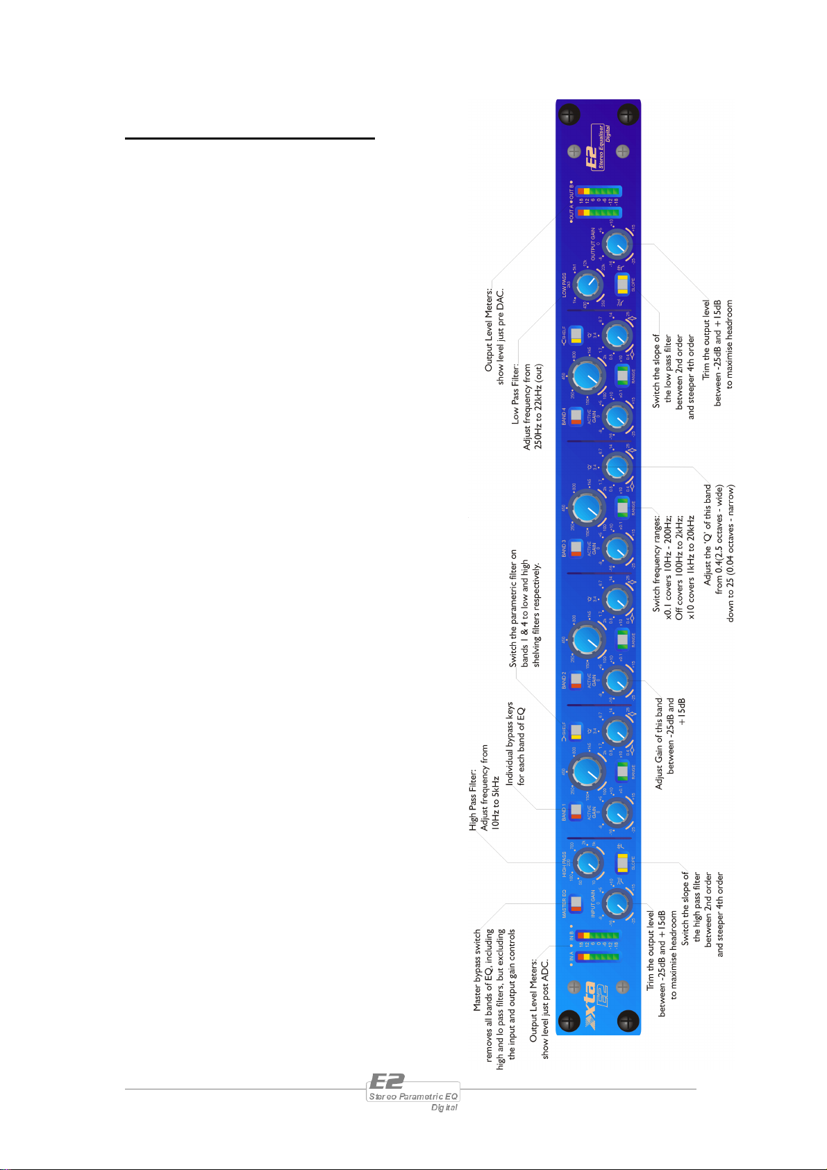
Front Panel Familiarisation
Input Level Meter: These meters permanently show
the level just after the analogue to digital converter, and
are not affected by any subsequent controls.
Master Key: Bypasses the entire channel – LED
illuminated when processing is active. All metering and
status LEDs for dim when the unit is bypassed.
Input Gain Control: If you are applying large amounts of
cut or boost it is best to turn down the input gain to prevent
the EQ stages clipping, rather than adjusting the level
entering the unit. This will ensure that the converter is still
being used over the widest resolution (and greatest number of bits), keeping noise at
a minimum.
High Pass Filter Control: Adjust the cut-off frequency of the high pass filter from
<10Hz (effectively off) to 5kHz.
High Pass Filter Slope Key: Choose either a second order response (12dB per
Octave roll-off) or a steeper 4th order response (24dB per Octave).
EQ Bands:
Active Key: Switch out just this band of Eq to
quickly gauge its effect.
Gain control: Adjust the amout of cut or obbst
of the selected band of frequencies. Note the
asymmetric nature of the control – 25dB of cut
is available, and 15dB of boost.
Frequency Control: In conjunction with the range key, select the centre frequency
of the band. In shelf mode, this sets the corner frequency of the shelf.
Range Key: Scale the frequency range available on the frequency control with this
key. The left hand LED illuminated means multiply the values by 0.1, so the control
covers 10Hz to 200Hz. No LEDs illuminated means the range is “x 1” so the control
covers 100Hz to 2kHz. The right hand LED means multiply the values by 10,
covering the range 1kHz to 20kHz.
Shelf Key: Bands 1 & 4 can have their response switched from a parametric (bell)
filter to a shelving response. Band 1 will become a low shelf, boosting all frequencies
below the selected frequency, and band 4 will become a high shelf, boosting all above
the selected frequency. Note that the ‘Q’ control will not have any effect when the
shelf mode is on.
‘Q’ control: In parametric mode, this will effect the width of the filter’s response.
Turned fully anti-clockwise the bandwidth is 0.4, or 2.5 octaves (a wide gently
response). Fully clockwise, the ‘Q’ is narrowed to 25, or 0.04 octaves.
E2 Operators Manual Page 7
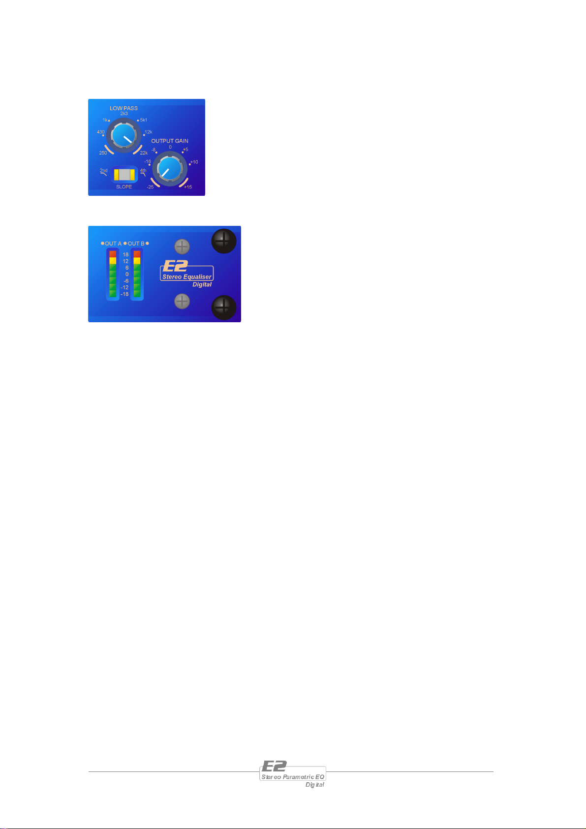
Low Pass Filter Control: Adjust the cut-off frequency of
the low pass filter from 250Hz to 22kHz(effectively off).
Low Pass Filter Slope Key: Choose either a second
order response (12dB per Octave roll-off) or a steeper 4th
order response (24dB per Octave).
Output Gain Control: To compensate for large amounts
of cut or boost and bring the output level back to that at
the input, use the output gain control, in conjunction with the meters.
Output Meters: These meters permanently show
the level after all processing, just before the digital
to analogue converters.
Page 8 E2 Operators Manual

Rear Panel Connections
Power Switch: turns the units mains supply off
and on.
Mains Fuse: located in a finger-proof holder
adjacent to the mains inlet. A spare fuse is also
located in this holder.
Mains Inlet: connected via a standard IEC socket.
Audio In-Out: 3 pin XLR sockets are provided for each
channel. All are fully balanced, pin 2 hot, 3 cold, 1
screen.
Always replace the fuse with the correct type and rating as
shown on the rear panel legend.
E2 Operators Manual Page 9

Operating the E2
Operation of the D2 is very straightforward, but there are a few points worth noting
which, once understood, will make using the unit even easier.
Switching the unit on and start-up procedure
After plugging in the power and switching the power on suing the rear panel switch,
confirmation is quickly given that all is well by all LEDs illuminating almost
immediately after power-up.
The LEDs of all ‘engaged’ keys (when the unit was last powered up) will illuminated,
and after the bypass relays disengage, a pattern will undulate across the LEDs as the
level fades up. The entire process is complete when the input/output meters begin to
operate normally. This whole start-up procedure only takes a few seconds.
Minimum and maximum control positions
To ensure that the E2 is 100%
accurate all of the time, and that what
it says on the front panel is exactly
what the unit is doing, it has been
necessary to introduce ‘end-stops’ on
the controls.
The extreme regions on each control
marked with the curved line designate
this entire region as relating to the
parameter value shown. This is to
compensate for the mechanical
tolerances of the potentiometers.
Page 10 E2 Operators Manual

Operating Notes
Operating Level
With any audio signal processing equipment it is necessary to ensure adequate signal
level is used through the device, to avoid sacrificing noise performance. It is suggested
that the operating level chosen should give adequate level to just light the -12dB LED
on the headroom meter with maximum program level being used. Since the meter is
deliberately set to show clipping 3dB early, this still provides 9dB of headroom before
clipping occurs. With equalisation in use it may be necessary to further reduce the
input level, as gain within the unit may cause digital clipping, indicated by the top red
LED's lighting independently of the rest of the meter.
It should be noted that the figure quoted for the maximum input level options is the
clipping point for that option (not a safe operating level). Always ensure that this
clipping point is no lower than that for the following equipment in the signal chain,
and allow extra margin if equalisation sections are boosted.
Grounding
The Screen (shield) pins on all audio connectors are normally connected directly to
the ground pin of the IEC mains inlet. The chassis is also directly connected to this
pin. Never operate this unit without the mains safety ground connected. Signal
ground (0V) is in turn connected to the chassis ground.
To avoid ground loops, cable shields should be connected to ground at one end only.
The normal convention is that the shield is only connected at the output XLR.
Provision is also made for separately isolating each input and output shield pin
permanently within the E2 by breaking the appropriate PCB track, where marked
with a box and an arrow next to each XLR connector using a small drill bit or cutter.
See the following diagram for details.
XLR pin 1 Isolation points (arrowed) and 10dB pads (circled)
E2 Operators Manual Page 11

Specifications
Inputs: 2 electronically balancedu
Impedance: > 10k ohms.
CMRR : >65dB 50Hz - 10kHz.
Outputs: 2 electronically balancedu
Source Imp: < 60ohms
Min. Load: 600ohm
Max. Level: +20dBm into 600 ohm
Frequency Resp.:+½dB 20Hz-20kHz
Dyn Range:>110dB 20Hz-20k unwtd
Distortion:< .02%@1kHz,+18dBm
High and Low Pass Filters:
Slope: Switchable 12dB/Oct
Butterworth or 24dB/Oct
Butterworth.
Parametric EQ Sections:
Type: Selectable low/high shelf (bands
1 & 4 resp.) or parametric response.
Centre/corner Freq: 20Hz to 20k in
three ranges
Input/Output Gain
Both +15 dB range.
Input meter: 7 point,
-18dBu to +18dBu.
Output meter: 7 point,
-18dBu to +18dBu.
Connectors
Inputs: 3 pin female XLR
Outputs: 3 pin male XLR.
Power: 3 pin IEC
Power: 60 to 250V ±15% @
50/60Hz.
Consumption: < 20 watts.
Weight : 3.5kg. Net (4.8kg.
Shipping)
Size: 1.75"(1U) x 19" x 11.8"
(44 x 482 x 300mm) excluding
connectors.
‘Q’: 0.4 to 25 (2.5 – 0.04 Octaves)
Gain: +15dB to –25dB
Options u = Transformers available.
Optional Interfaces AES/EBU Digital Input/Output
Due to continuing product improvement the above specifications are subject to change.
Page 12 E2 Operators Manual

Warranty
This product is warranted against defects in components and workmanship only, for a
period of one year from the date of shipment to the end user. During the warranty
period, XTA will, at it's discretion, either repair or replace products which prove to
be defective, provided that the product is returned, shipping prepaid, to an
authorised XTA service facility.
Defects caused by unauthorised modifications, misuse, negligence, act of God or
accident, or any use of this product that is not in accordance with the instructions
provided by XTA, are not covered by this warranty.
This warranty is exclusive and no other warranty is expressed or implied. XTA is not
liable for consequential damages.
Options and Accessories
Part Number Part Description
ITX-100
OTX-100
E2 Transformer balanced inputs (factory fitted only)
E2 Transformer balanced outputs (factory fitted only)
AES-E2 AES/EBU Digital inputs/outputs (factory fitted only)
E2 Operators Manual Page 13
 Loading...