

Page 1

Page 2
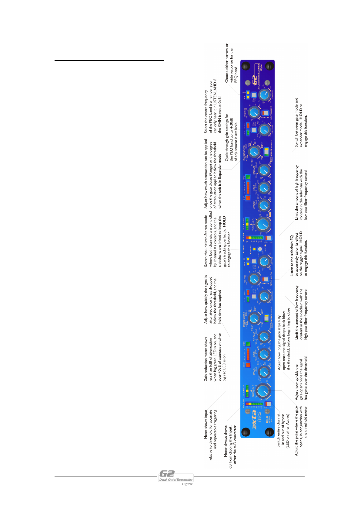
G2 Quick Reference
THINGS YOU NEED TO KNOW…
ü BOLD MEANS HOLD!
Any functions that would produce possible
unexpected level changes at the outputs are
protected by a ‘press and hold’ action and
printed in BOLD on the panel. These functions
are:
Changing MODE between Gate and Expander;
Enabling the sidechain LISTEN function;
Ganging the two channels together in STEREO
mode.
ü The main meters show level, in dB, from
the clipping point of the input of the unit
just after the analogue to digital
converter stage. As the unit is unable to
add any gain to the signal, there is no
need for an output meter.
ü When in Expander mode, the Hold knob
has no effect.
ü Remember that you won’t hear the
effect of the parametric sidechain band,
unless there is cut or boost applied – use
the GAIN switch to cycle through the
levels.
ü The Listen LED always flashes when
Listen is enabled. Listen is automatically
turned off if the unit is switched off and
on.
ü Remember that the Range/Ratio control
applies to both modes of operation – the
values in the boxes are for Gate mode,
and are in dB, the other values are ratios
for Expander mode.
Page 2 G2 Operators Manual
Page 3

Contents
G2 Quick Reference 2
Important Safety Information 4
Thanks 5
Unpacking the G2 5
Introduction 6
Features 6
Front Panel Familiarisation 7
Rear Panel Connections 9
Operating the G2 10
Switching the unit on and start-up procedure 10
Press-and-hold Keys 10
Minimum and maximum control positions 10
Noise Gate Know-how 11
Attack and Release Times. 11
Setting the Range Correctly. 13
Using the Hold Time. 13
Expanders and Expansion – the subtler approach 15
What does an Expander do? 15
Why are Expanders necessary? 15
How does a Expander work? 16
What is the difference between an Expander and a Noise Gate? 18
Sidechain Equalisation – How and When to Use it 19
When would Sidechain EQ be useful? 19
How would sidechain EQ normally be implemented? 19
Picking out instruments for gating. 19
Look Ahead Delay – Pre-emptive Action 21
Setting the Attack and Release times 24
Gate and Expand MODE 25
STEREO Linking 25
Operating Notes 26
Operating Level 26
Grounding 26
Specifications 27
Warranty 28
Options and Accessories 28
G2 Operators Manual Page 3
Page 4

An example of this equipment has been tested and found to comply with
the following European and international Standards for Electromagnetic
Compatibility and Electrical Safety:
Radiated Emissions (EU): EN55013-1 (1996)
RF Immunity (EU): EN55103-2 (1996) RF Immunity, ESD, Burst Transient,
Surge, Dips &Dwells
Electrical Safety (EU): EN60065 (1993)
Important Safety Information
Do not remove Covers.
No user serviceable parts inside, refer servicing to qualified service personnel.
This equipment must be earthed.
CAUTION
RISK OF ELECTRIC SHOCK
DO NOT OPEN
DO NOT EXPOSE TO RAIN OR MOISTURE
ATTENTION
RISQUE DE CHOC ELECTRIQUE
NE PAS ENLEVER
NE PAS EXPOSER A LA PLUIE NI A L’HUMITE
It should not be necessary to remove any protective earth or signal cable shield connections.
Do not defeat the purpose of the polarized or grounding-type plug. A polarized plug has two
blades with one wider than the other. A grounding type plug has two blades and a third
grounding prong. The wider blade and the third prong are provided for your safety. When the
provided plug does not fit into your outlet, consult an electrician for replacement of the obsolete
outlet.
Only use this equipment with an appropriate mains cord.
In the USA the cord should comply with the requirements contained in the Standard for Cord
Sets and Power Supply Cords, UL 817, be marked VW-1, and have an ampacity rating not less
than the marked rating of the apparatus.
Page 4 G2 Operators Manual
Page 5
Thanks
Thank you for choosing the XTA G2 Dual Gate/Expander for your application.
Please spend a little time reading through this manual, so that you obtain the best
possible performance from the unit.
All XTA products are carefully designed and engineered for cutting-edge
performance and world-class reliability. If you would like further information about
this or any other XTA product, please contact us.
We look forward to hearing from you in the near future.
Unpacking the G2
After unpacking the unit, please check it carefully for any damage. If any is found,
immediately notify the carrier concerned - you, the consignee, must instigate any
claim. Please retain all packaging in case of future re-shipment.
G2 Operators Manual Page 5
Page 6

Introduction
The G2 is a powerful DSP based audio dynamics processor, ideally suited for live
sound applications, where it combines the accessibility and immediacy of a pure
analogue design with the quality and accuracy of a digital design in a compact 1U unit.
To achieve this, the G2 has an analogue control surface, following the ‘one control –
one function’ philosophy and a pure digital signal path, with 24-bit conversion, 40-bit
internal processing and a professional 48kHz sampling rate.
The G2 is also available with optional AES/EBU digital inputs and outputs.
Features
♦ Look ahead attack for true ‘clickless’ operation and instantaneous opening of
the gate
♦ Fully adjustable envelope controls, including hold time (in Gate mode) with
large, easy to see, metering
♦ Sidechain EQ built-in including low and high pass filters, and an additional
parametric section with variable stepped gain and high-resolution
frequency adjustment
♦ Expander mode – for more subtle gating applications, with gain reduction
metering and fully variable ratio control
♦ Stereo link mode locks the sidechains together for perfect stereo tracking as
well as parameter matching
♦ Threshold metering to allow accurate and repeatable triggering of the gate
♦ AES/EBU Digital input and output interfaces are available as an option.
♦ Input and output balancing transformers are also available as an option.
Page 6 G2 Operators Manual
Page 7
Front Panel Familiarisation
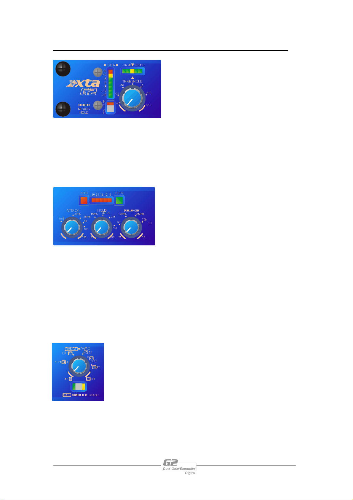
Level Meter: this meter displays the
instantaneous available headroom available at
the input, just after the analogue to digital
converter.
Active Key: Switches the entire channel
on/off – LED illuminated when processing is
active. Note that the Listen mode may still be
active when the channel is bypassed.
Threshold Control: Set the threshold at which the gate will open, from -40dBu to
+22dBu (effectively off).
Threshold Meter: This meter display the closeness to the threshold, ranging itself
dependant on the setting of the Threshold control and the input level. The yellow
LED shows the point at which the gate will open.
Attack Control: Set how fast the gate will
open (the fade-in time) – the ‘60uS’ setting uses
look ahead delay to open the gate before the
main signal arrives, so preserving the entire
waveform.
Hold Control: Set how long the gate stays fully
open after the signal has dropped below the
threshold, and before entering the release phase.
Release Control: Once the signal has dropped below the threshold and the hold
time has expired, this control determines how quickly it is attenuated (the fade-out
time).
Gate and Gain Reduction Metering: The large green LED is only ever illuminated
when there is less than 6dB of attenuation on the channel (so effectively the gate is
fully ‘open’). As the attenuation increases, this LED goes off, and the red meter
begins to illuminate right to left. This shows increasing gain reduction, until the final
large red LED illuminates when there is more than 40dB of attenuation.
Range/Ratio Control: In Gate mode, this control sets the
maximum attenuation allowed (the Range) when the gate is fully
closed. Note that if the Range is set to less 40dB, the large RED
led may never illuminate. In Expand mode, this control
determines the degree of attenuation as the signal drops below
the threshold.
MODE Key: Switch the channel between Gate mode and
Expand mode. HOLD this key to change modes. Note that the
control markings for Gate mode range are boxed.
G2 Operators Manual Page 7
Page 8
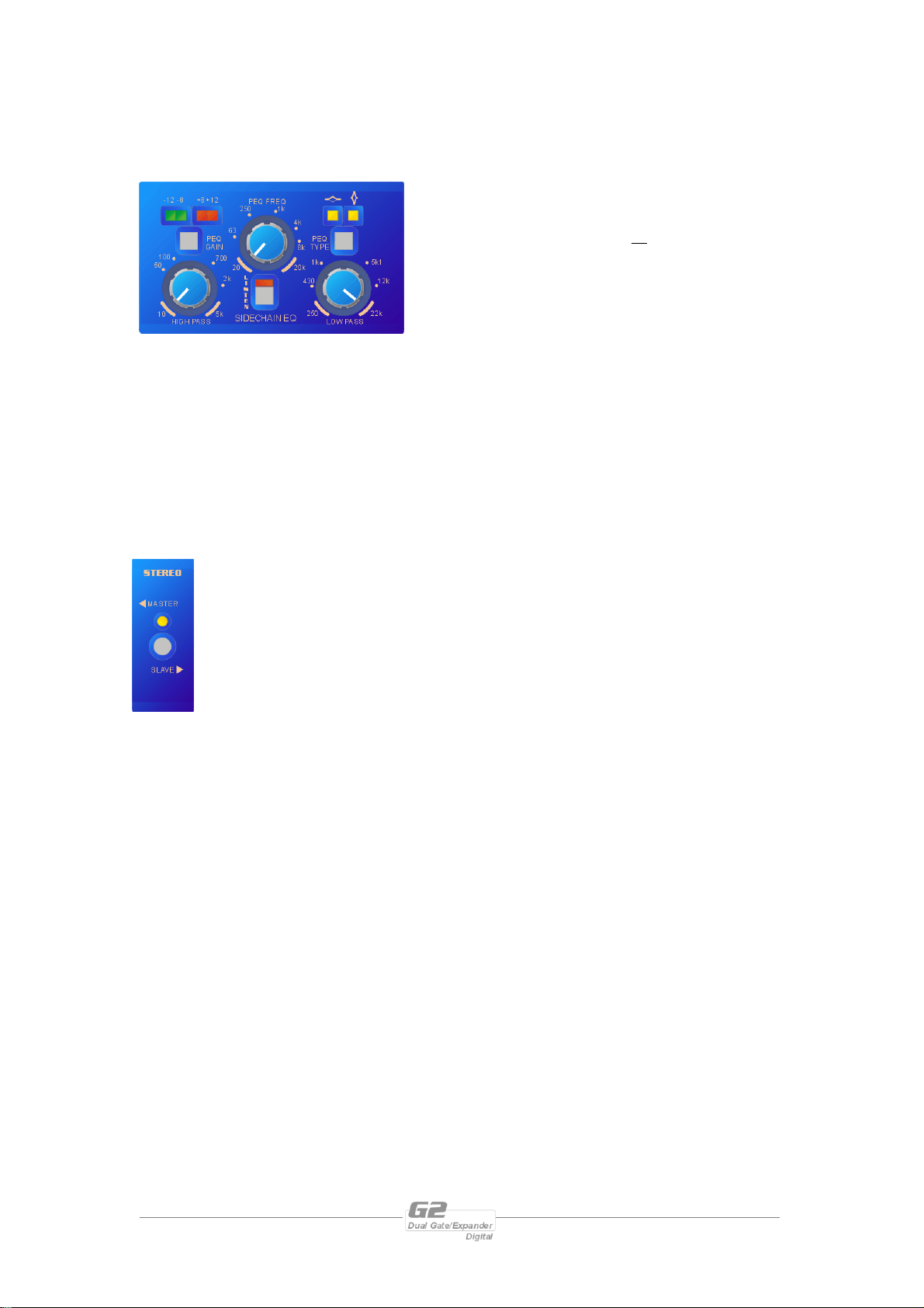
Sidechain PEQ Gain Key: Adjust the gain of
the sidechain filter to sensitise or desensitise the
gate to certain frequencies. +8/12/20(!) of gain
is available, as well as 0db (off).
Sidechain PEQ Type: Choose the shape of
the sidechain filter between, narrow ‘Q’
parametric and ‘wide ‘Q’ parametric.
Sidechain PEQ Frequency: Select the frequency range over which the sidechain
filter will operate.
High Pass Frequency Control: Cut low frequency content out of the sidechain
signal up to 5kHz.
Low Pass Frequency Control: Cut high frequency content out of the sidechain
signal down to 250Hz.
LISTEN Key: Switches the output of the sidechain filter into the main signal path,
so that the required range of frequencies may be more easily selected. LED flashes as
a reminder that this is selected. HOLD to engage this function.
STEREO Key: Enabling the ‘Stereo’ mode will disable the right hand set
of controls and force both channels to assume the parameter values of the
left channel. The sidechains are also linked so that the two channels track
perfectly, maintaining the stereo image.
Page 8 G2 Operators Manual
Page 9
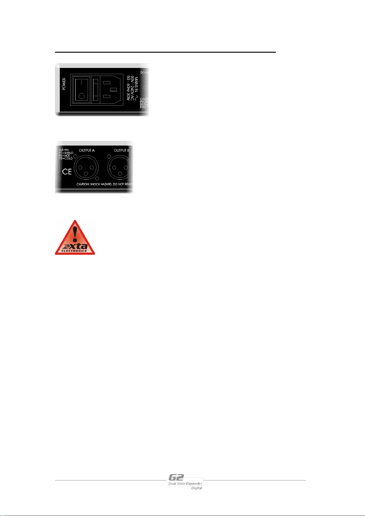
Rear Panel Connections
Power Switch: turns the units mains supply off
and on.
Mains Fuse: located in a finger-proof holder
adjacent to the mains inlet. A spare fuse is also
located in this holder.
Mains Inlet: connected via a standard IEC socket.
Audio In-Out: 3 pin XLR sockets are provided for each
channel. All are fully balanced, pin 2 hot, 3 cold, 1
screen.
Always replace the fuse with the correct type and rating as
shown on the rear panel legend.
G2 Operators Manual Page 9
Page 10
Operating the G2
Operation of the G2 is very straightforward, but there are a few points worth noting
which, once understood, will make using the unit even easier.
Switching the unit on and start-up procedure
After plugging in the power and switching the power on using the rear panel switch,
confirmation is quickly given that all is well by various status LEDs illuminating almost
immediately after power-up. These will include, as a minimum, MODE
(Gate/Expand); and Sidechain EQ Type (Wide/Narrow ‘Q’).
The gain reduction will animate and, after the bypass relays disengage, begin to ‘count
down’ accompanied by the output level fading up to normal operating level.
The entire process is complete when the input/output meters and gain reduction
begin to operate normally. This whole start-up procedure only takes a few seconds.
Press-and-hold Keys
The legending on the front panel alerts the user to
the fact that several keys require a ‘press and hold’
action to initiate them. These keys relate to
functions that could accidentally introduce large
changes of level at the outputs, causing undesirable
effects and possible damage. These keys have their
function marked in BOLD (and a different font) to
make it clear that they will only change state if the
key is held in for a time.
The keys in question are…
MODE – switching between gate mode and expand mode (See page 25)
LISTEN – switching the output to monitor the sidechain EQ signal (See page 19)
STEREO – linking the two channels together to operate in stereo (See page 25)
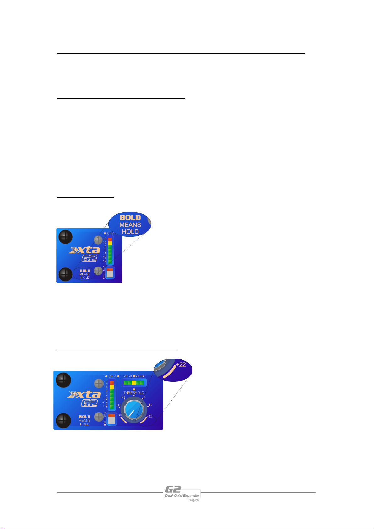
Minimum and maximum control positions
To ensure that the G2 is 100%
accurate all of the time, and that what
it says on the front panel is exactly
what the unit is doing, it has been
necessary to introduce ‘end-stops’ on
the controls.
The extreme regions on each control
marked with the curved line designate
this entire region as relating to the parameter value shown. This is to compensate for
the mechanical tolerances of the potentiometers.
Page 10 G2 Operators Manual
Page 11
Noise Gate Know-how
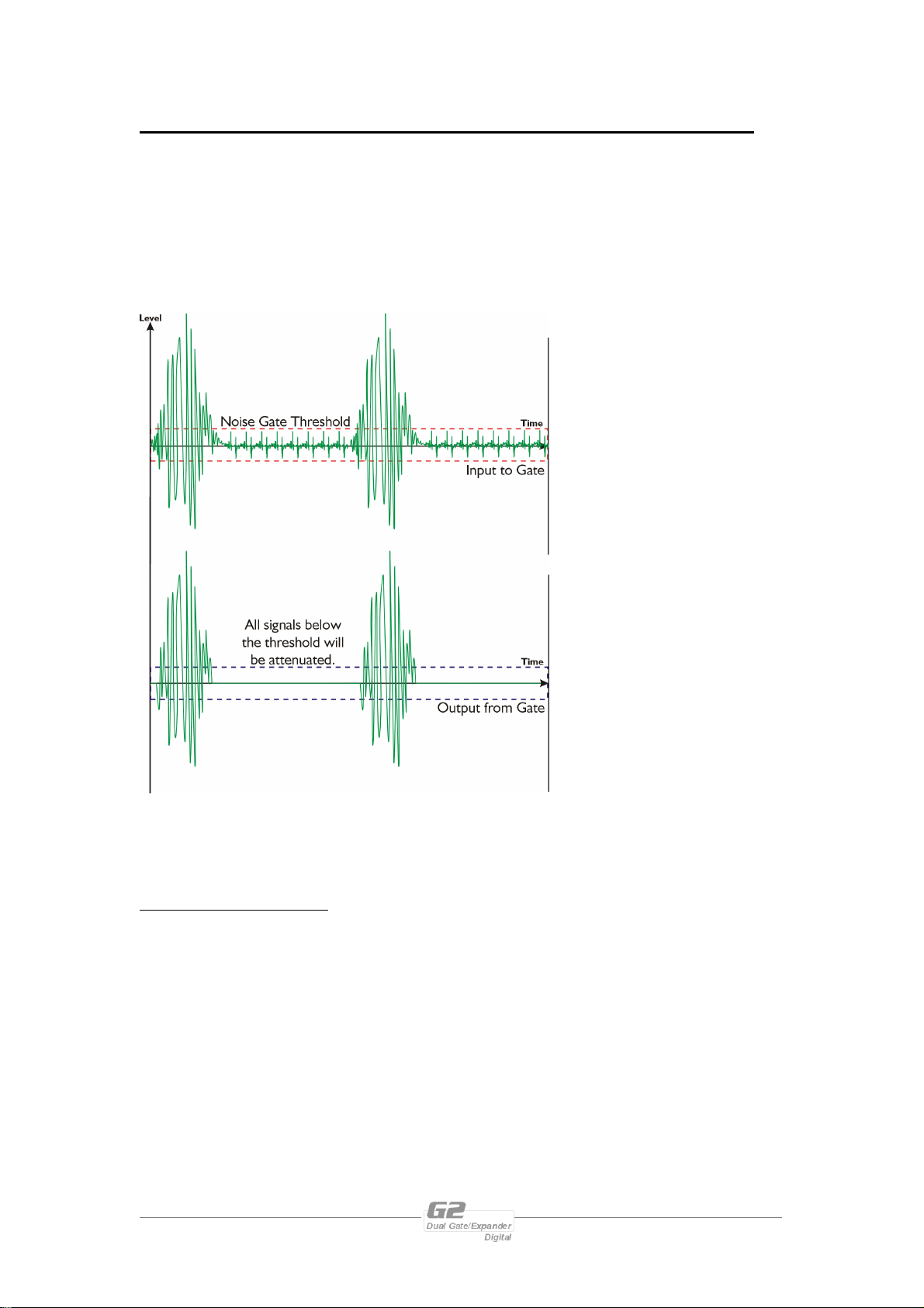
Most engineers know the principle reason for using a noise gate – to shut off the
output of some device that, in the absence of the desired output signal, produces (or
passes on) an undesirable level of background noise. The behaviour of the noise gate
is controlled by adjusting, principally, its threshold. This sets the point at which the
level of the desirable signal is deemed quiet enough to turn it off, thereby cutting off
all the background noise as well.
Considering the diagram
shown here, the desired
signal would be the high level
burst and, in between, low
level noise. An example of
this scenario might be the
signal from a bass drum
microphone – a burst of
signal, but perhaps with
unwanted pickup from
lighting dimmers producing a
background buzz.
Setting the threshold just
above the level of the buzz
would keep the gate closed
during periods were the bass
drum was not being played,
only allowing signal through
when the output would be
sufficient to mask the noise
anyway.
The output graph above highlights several other points that are particularly important
with noise gates.
Attack and Release Times.
As the gate opens, there will be a finite delay before the signal crosses the threshold,
cutting off part of the start of the desired signal’s envelope. Similarly, as the signal
drops below the threshold, the gate will close, cutting off some of the end of the
envelope. The diagram above is not truly representative of how the signal
approaching the threshold would be affected.
G2 Operators Manual Page 11
Page 12
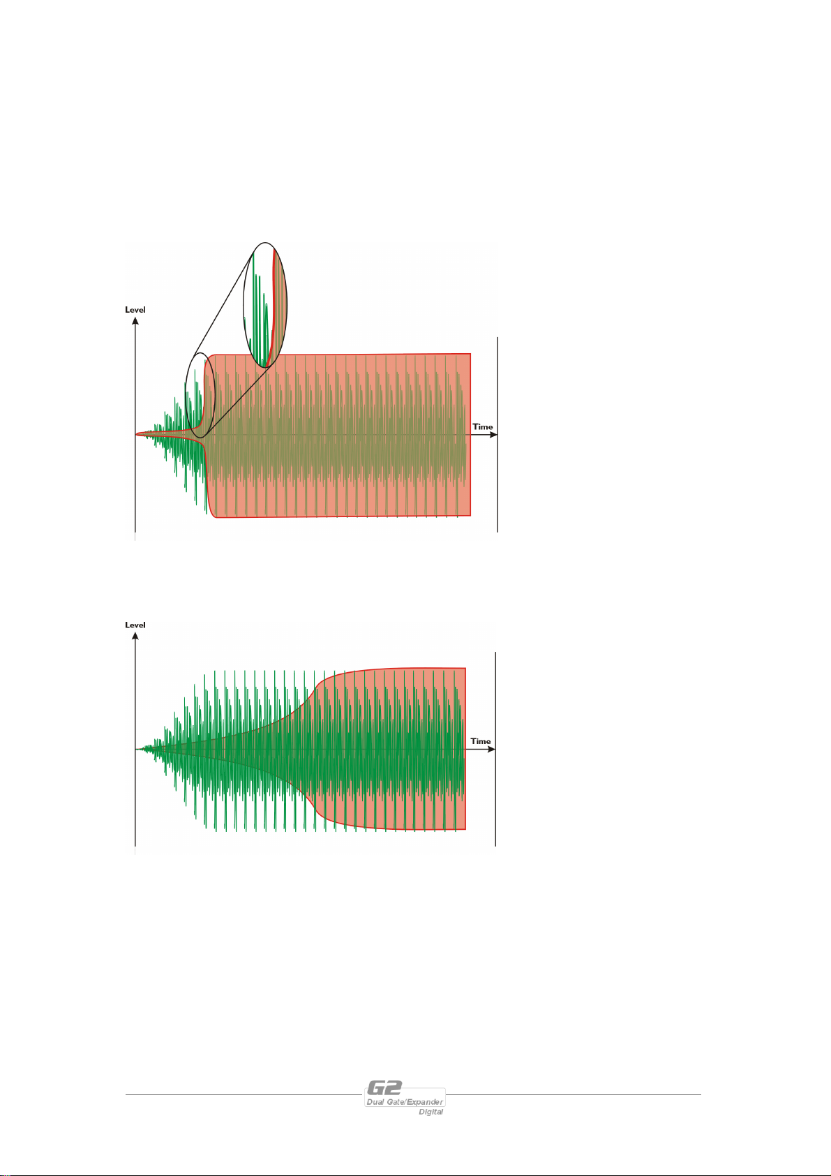
Controlling the speed at which the gate opens (attack time) and closes (release time)
is crucial to providing transparent operation. Setting the attack time too fast on a
signal that naturally has a relatively slow attack will produce a click. Such a case often
occurs when gating the human voice. The attack time for typical speech or singing is
in the order of several milliseconds – setting the gate to faster than this will make the
voice ‘appear out of nowhere’ with an audible click. This is due to the sudden change
in level from the gate being closed to fully open. The fact that this is a large transient
change will make it sound
Sudden jump in level as the
gate opens appears as a
click at the start of the
signal.
like a click. Changing the
‘distance’ between the gate
being closed and open will
remove this click, but also
defeat the purpose of the
gate in the first place – if the
range is set high enough to
prevent the click, it’s
probably not gating the
signal enough anyway.
As mentioned earlier, if the attack is set too slow, the gate will not open in time, and
part of the signal will be lost. For most musical instruments, the essential part of the
signal is the attack phase, as this part identifies the instrument to the human ear.
Start of signal has been lost due
to slow opening of the gate.
Hearing only the sustain or
release of a sound makes it
difficult to discern what type
of instrument is being
played, and sounds very
unnatural.
Page 12 G2 Operators Manual
Page 13
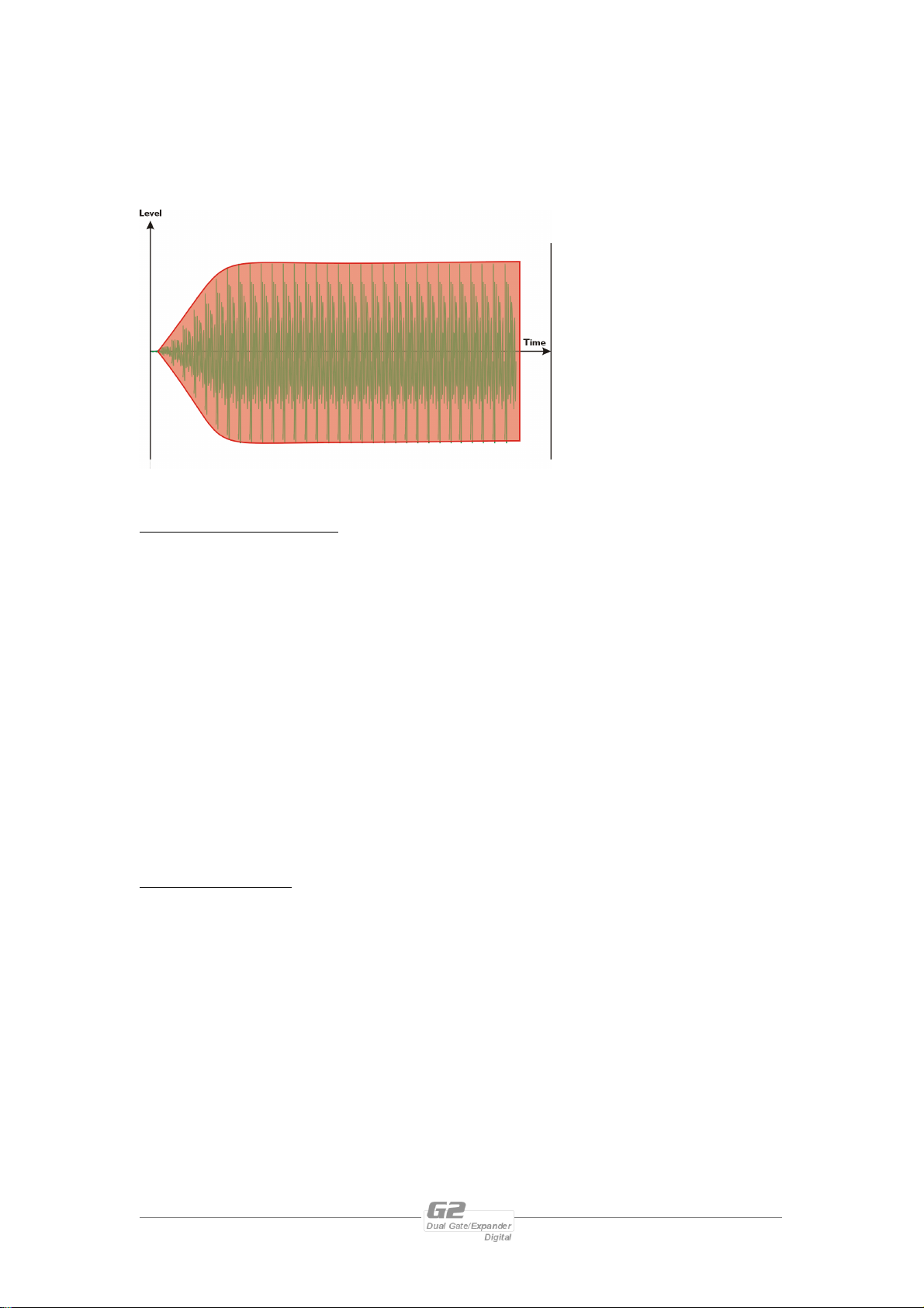
Setting a sympathetic attack time that is similar to that of the required signal will
produce the most natural and transparent results. As the diagram below
demonstrates, the gate opens at a similar rate to the signal, allowing the full attack
portion to be heard.
The same rule applies to the
release of the gate – but for
slightly different reasons.
Too slow a release, and
some of the background
noise will be heard as the
gate closes; too fast, and the
signal will be prematurely
cut off, sounding unnatural.
Setting the Range Correctly.
The range control sets how much attenuation is applied to a signal once it drops
below the threshold and closes the gate. It is quite often overlooked when setting up
a gate, the temptation being to set the range at maximum and leave it. When the
gate is fully closed, no signal will be heard when the range is set like this. In some
situations, this much attenuation can sound quite unnatural, especially if the threshold
is set high to gate a loud signal, due to the stark contrast between the gate fully closed
and fully open.
It’s also worth remembering that if the background noise is quite severe, removing it
all will only highlight the noise more when the gate opens and the noise becomes
apparent again. It’s often better to set the range to around 25-30dB of attenuation so
that it can still be heard very slightly.
Using the Hold Time.
When the gate is being used with transient signals that require fast attack but
relatively slow decays, it can be beneficial to introduce a hold time into the gates
envelope. This has the effect of prolonging the time the gate stays open, after the
signal drops below the threshold. The diagram overleaf explains this concept.
G2 Operators Manual Page 13
Page 14
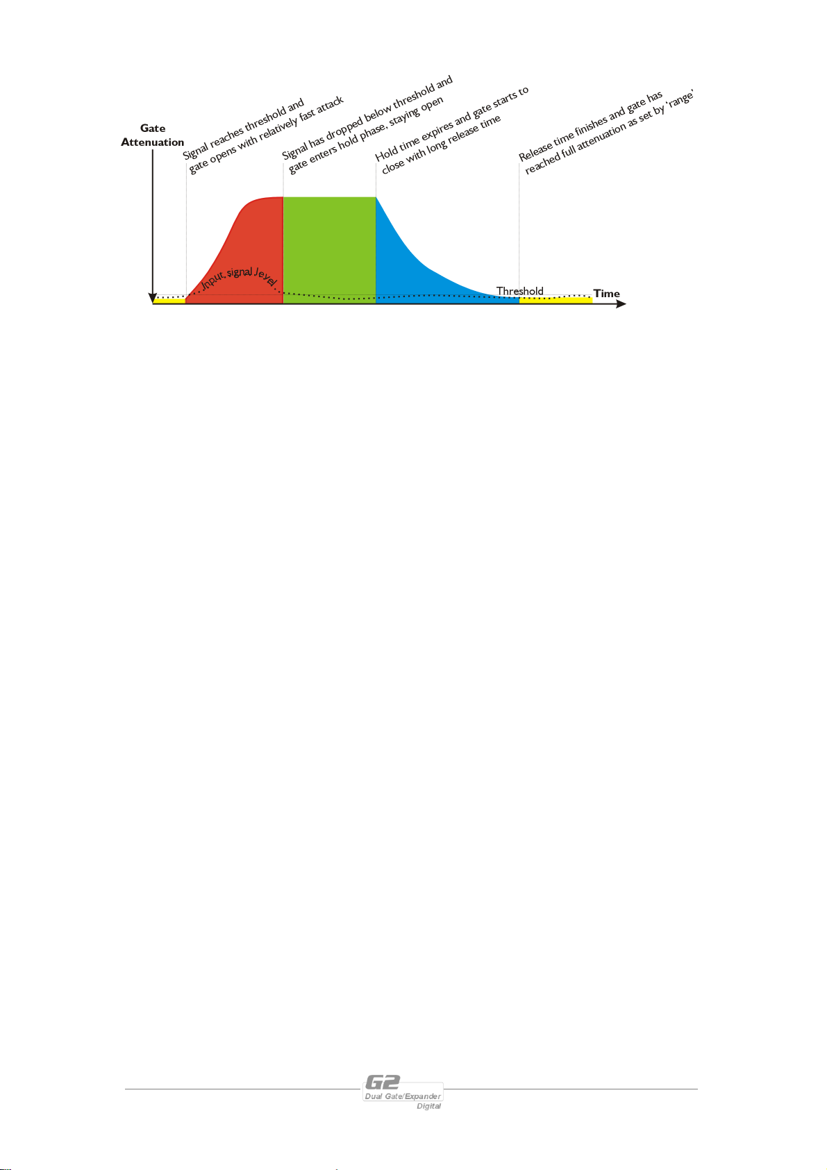
Adding some hold time to the envelope can help with tricky situations where the gate
might open and close erratically, such as when there is a lot of background noise.
This problem, coupled with a long release, can cause sporadic bursts of noise to open
the gate in situations when it would be better to hold it open slightly longer.
Page 14 G2 Operators Manual
Page 15

Expanders and Expansion – the subtler approach
What does an Expander do?
An expander can be thought of as a complementary device to a compressor. Whilst a
compressor is designed to compress the dynamic range of a signal, an expander is
designed to expand it. The threshold at which the expander begins to operate sets
the point below which the signal begins to be attenuated by a certain amount. The
fact that signals are only ever attenuated defines the behaviour as ‘downward
expansion’ in nature. This distinction is important because if the expander was to
process the dynamic range at a certain threshold, attenuating below the threshold
and amplifying above, even with a low ratio of perhaps 3:1, a limited dynamic range
signal might well end up with a dynamic range well in excess of 120dB, which would
be impossible to utilise, even with the best equipment.
Why are Expanders necessary?
The main use for an expander is to improve the dynamic range of an instrument or
processing device. The dynamic range of any device is limited by two factors – it’s
minimum output, and it’s maximum. It would seem reasonable to assume that the
minimum output would be exactly zero, and that this level should be the same for all
devices. This is definitely not the case. Certainly, when the majority of instruments
and devices are turned off (assuming they are powered in some way) they will all
share a similar minimum output level. However, once on, it is the noise floor of the
electronics within that determines the minimum output. A signal that is below the
noise floor of any piece of equipment will not be resolved by that equipment.
The maximum output level is largely determined by the power supply capabilities of
the device. Many manufacturers (especially Far Eastern) tend to use power supplies
with lower voltage rails, resulting in a poor drive capabilities and limited maximum
output level.
As the expander functions below the threshold, it is in the area of minimum output
level that improvements can be made. Thinking laterally, the noise floor need not just
refer to the electronically generated variety. Noise can be thought of as any
“irregular fluctuations accompanying a transmitted signal but not relevant to it”1.
This may now include other sources of noise such as:
♦ Hum due to poor power supply regulation or induced by an earth loop
♦ Background interference from lighting dimmers
♦ Stage noise picked up from a microphone or transmitted up a microphone
stand
♦ Handling noise from a microphone
♦ Overspill when ‘miking-up’ a drum kit
1
Concise Oxford English Dictionary 2000 Definition 3.
G2 Operators Manual Page 15
Page 16
An expander can be used to improve the noise floor under all these circumstances, by
attenuating signals below a set threshold, thereby improving the clarity of the signal
fed to it.
One other area where expander can prove useful is in the control of feedback in a
live situation. In the case of a vocal microphone, leaving it ‘open’ all the time is likely
to cause problems not only with the pick-up of extraneous noise, but allowing
feedback paths to build up. Whilst the vocalist is actually using the microphone, their
voice effectively stops all other sounds from entering. By attenuating the output from
the microphone during pauses, the build up of feedback can be avoided.
How does a Expander work?
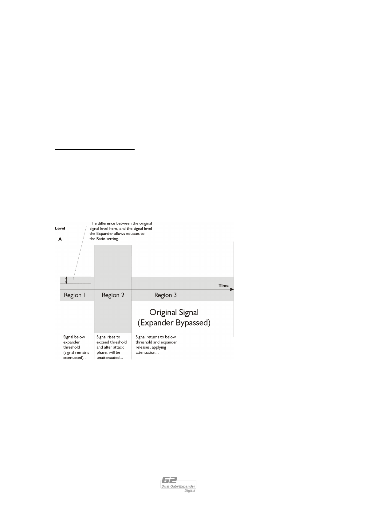
Consider again the signal burst shown below. Regions 1 and 3 are set to below the
threshold of the expander, and will consequently be attenuated by an amount
equating to the Ratio parameter. In region 2, the signal has risen to a level above the
threshold, and so the expander will stop attenuating, and allow the signal to pass
straight through. The difference between the attenuated signal when below the
threshold and the original signal level (i.e. the degree of attenuation) is set by the
Ratio.
Continuing with the
compressor analogy
again – the ratio can be
determined by
considering the degree
of attenuation required.
If the signal drops to
6dB below the
threshold, and the
ratio is set to 2:1, then
the actual output will
be 12dB down.
The expander is equipped with a set of envelope controls, which allow adjustment of
how it reacts to the signal as it crosses the threshold.
Page 16 G2 Operators Manual
Page 17
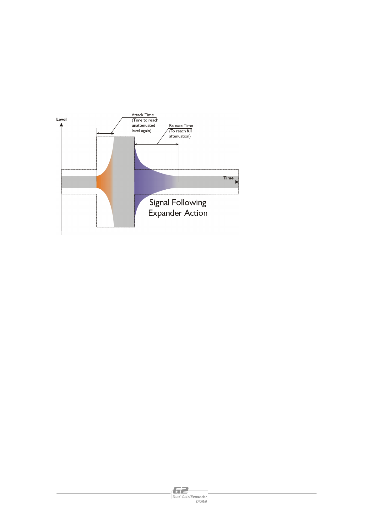
Examining the purple shaded area in region 3, this represents the release time of the
expander- that is the time for it to achieve full attenuation by the amount set with the
Ratio control, once the signal has dropped below the threshold. The orange shaded
area in region 1represents the attack time of the expander. This is the time period
for the expander to return to the unattenuated level again, the signal having risen
above the threshold. As with a compressor, the setting of the envelope controls is as
important as choosing the correct threshold.
Expanders are
susceptible to the same
abuse as compressors
as far as adjustment of
the envelope controls is
concerned. If the
attack time is too fast,
there will be an audible
‘click’ as the attenuated
signal rises above the
threshold and normal
(unattenuated) gain is
reapplied.
G2 Operators Manual Page 17
Page 18
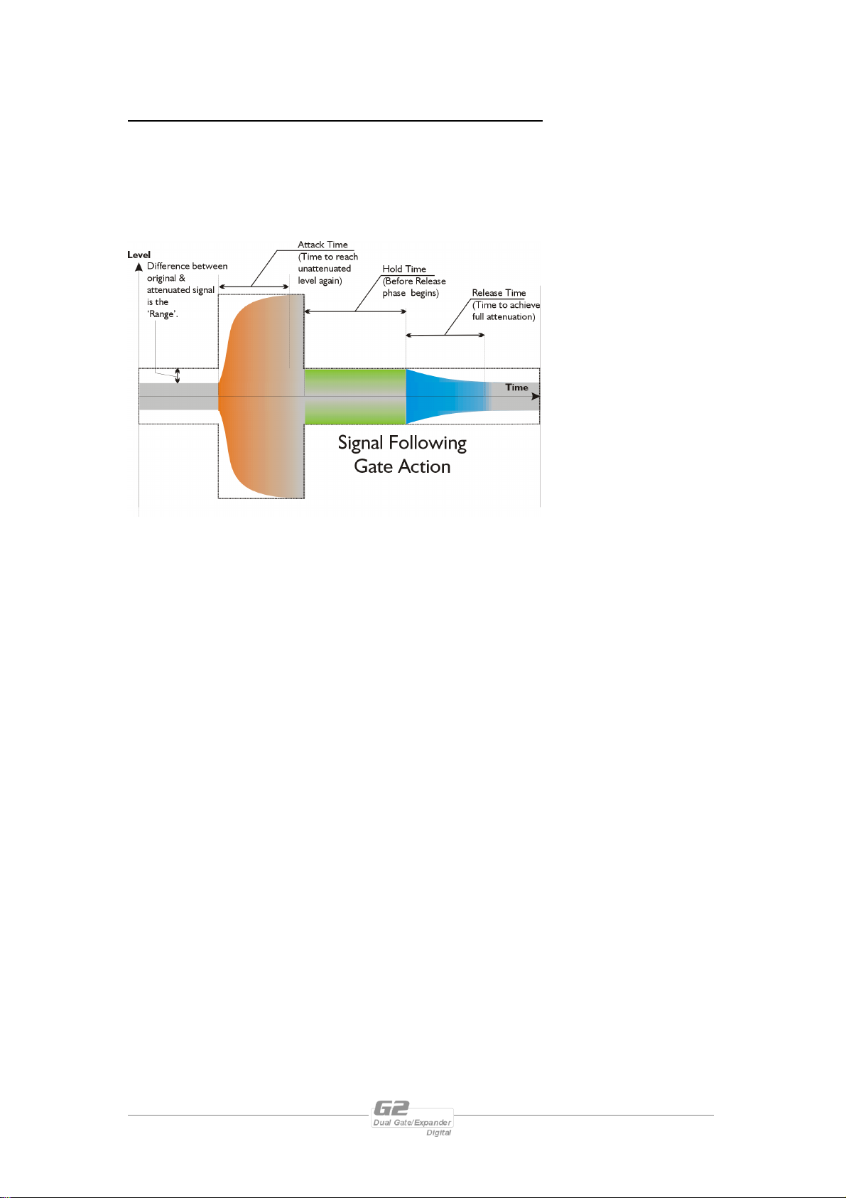
What is the difference between an Expander and a Noise Gate?
In the same way as a limiter can be thought of as a compressor with an infinitely high
ratio, a noise gate is an expander with an infinite ratio. As the expander and noise
gate share similar controls and ultimately work in the same way, consider the burst
diagram below, which demonstrates the action of a noise gate.
As the signal in region
1, is below the
threshold set for the
gate to be ‘open’, the
output will be
attenuated. The
amount of attenuation
applied is not
dependant on a ‘Ratio’
this time, but on the
‘Range’ control setting.
This determines the attenuation in dB’s, which is applied to all signals below the
threshold irrespective of how far below the threshold they are. Whilst the expander
gradually applies attenuation to a greater degree as the signal falls further below the
threshold, the gate will ‘close’ below the threshold applying the number of dB’s of
attenuation set by the ‘Range’ control. If, for example, the threshold is set to 0dB,
and the level drops to –10, if the ‘Range’ is set to 20dB, then the output will be
-30dB: -10 with 20dB of attenuation.
The orange region represents the ‘Attack’ phase of the noise gate, as the signal rises
above the threshold and the gate ‘opens’. The green shaded section is the ‘Hold
Time’ parameter. This has been explained in the earlier section ‘Using the Hold
Time’ in the noise gate section on page 13.
Page 18 G2 Operators Manual
Page 19
Sidechain Equalisation – How and When to Use it
When would Sidechain EQ be useful?
When it is necessary to adjust the sensitivity of the gate, tailoring the sidechain signal
with equalisation is the only way to achieve this without affecting the main signal path.
How would sidechain EQ normally be implemented?
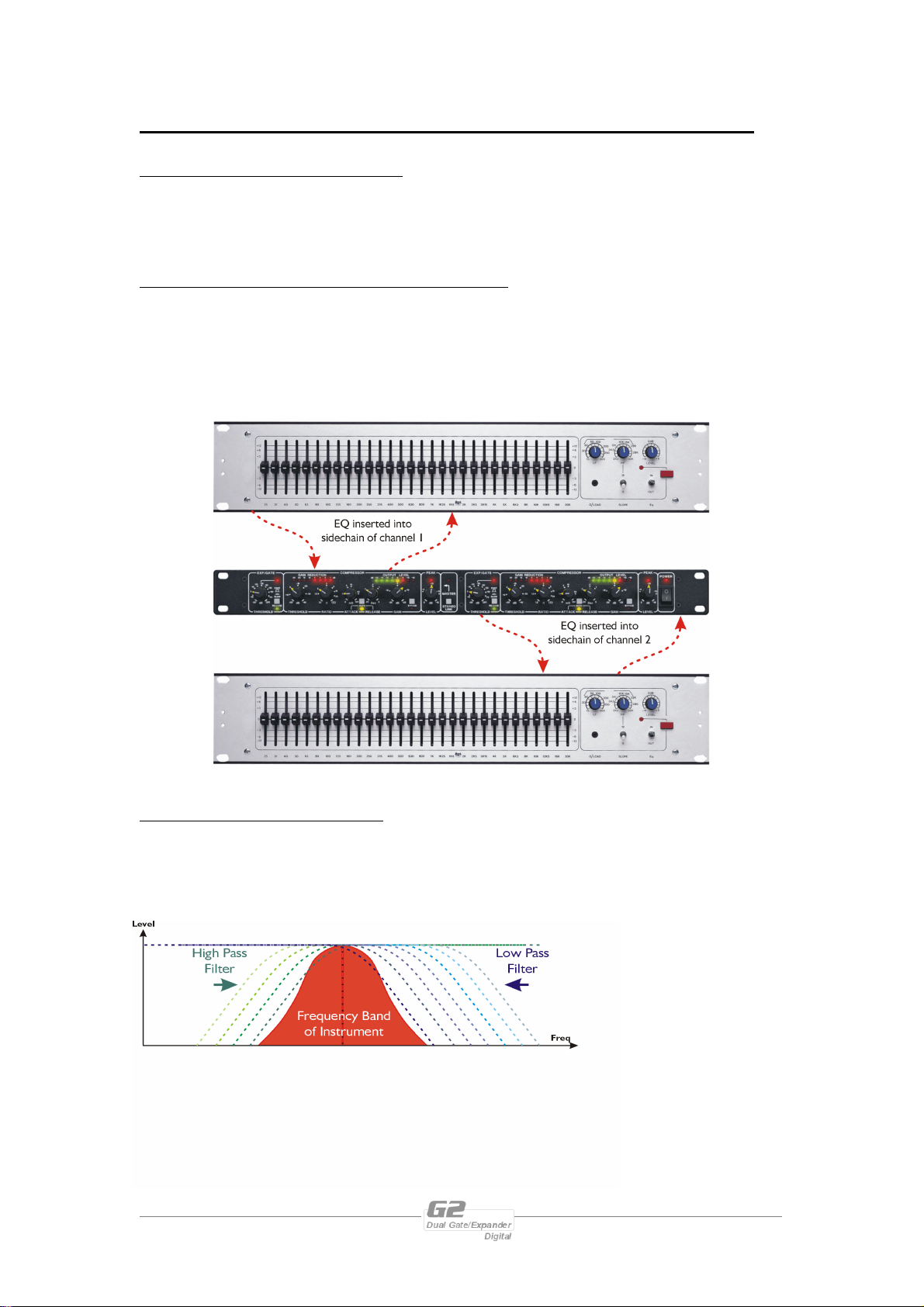
Typically, sidechain EQ would be patched into the in/out external path as offered by
the dynamics processor. The G2 obviates the need for this external processing by
including both standard high and low pass filters, and a full frequency band of
parametric EQ in the side chain for each channel.
Picking out instruments for gating.
Sidechain EQ is most often associated with homing in on a band of frequencies to
improve the performance of a noise gate. Being able to exclude extraneous program
material will make the triggering of a gate much more reliable and easier to set up.
The G2’s noise gate (and
expander) offers not only
the high and low pass
filters, but an additional
band of fully parametric
EQ per channel.
G2 Operators Manual Page 19
Page 20
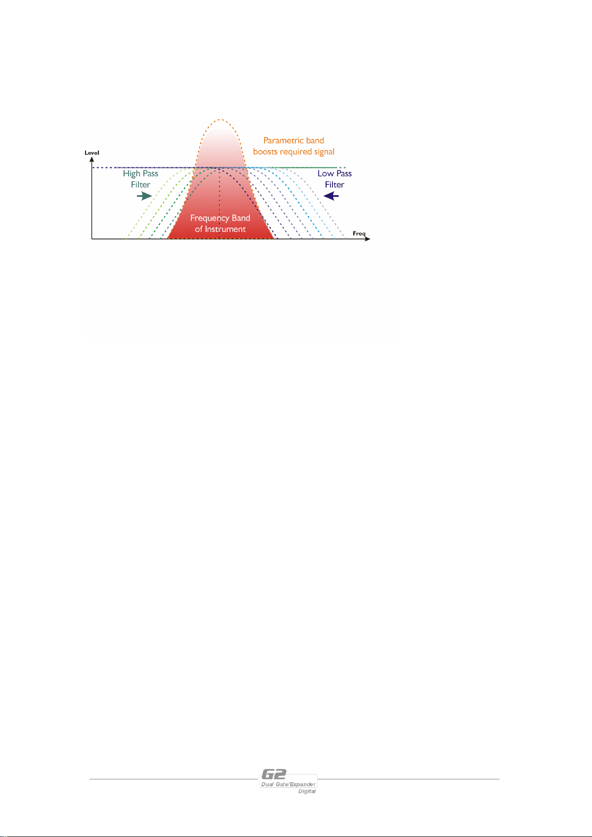
This allows the high and low pass filters to be used for the removal of extraneous
of frequencies. This can prove very useful in situations where there may
program material as normal, but also the parametric to ‘highlight’ any particular band
be limited difference between the wanted and unwanted signals.
Being able to accentuate
the wanted band at the
same time as attenuating
the unwanted material,
especially with the added
possibility of highlighting
an one area for triggering
could prove invaluable.
Page 20 G2 Operators Manual
Page 21
Look Ahead Delay – Pre-emptive Action
One of the most significant advantages of digital signal processing over analogue is the
ability to delay the audio signal precisely and without extensive complex hardware.
The entire domain of digital signal processing is based around the combination of
delaying, multiplying, and accumulating numbers (representing samples of audio) to
implement all the filters and dynamics processing we have come to expect today.
In the case of dynamics processing, being able to delay a signal allows the processor
module to delay the main signal in relation to the sidechain (the signal being
monitored relative to the threshold), so that it can compensate for peaks prior to the
arrival of the main signal.
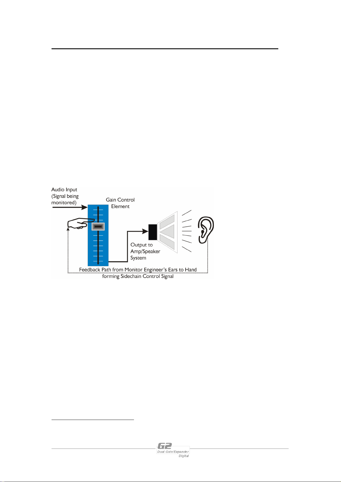
Consider the situation of a monitor engineer listening to a band perform2. Having no
access to dynamics processors, he has had to resort to manually ‘riding the faders’ in
an attempt to keep control of the levels. Should the level of one of the channels on
his desk reach an unacceptably high level, he will turn it down appropriately.
There is a hidden
sidechain in operation
even in this case. The
main signal path is fed
through the monitor
desk and the gain
controlled by adjusting
the fader. The sidechain
is formed by the
feedback path between
the engineer’s ears
checking the level and his
brain instructing his hand to turn the fader down if the volume goes over the
threshold he has chosen.
In this case, the delay between the signal actually going over the threshold, the
engineer registering the situation, and then turning the signal down will be in the
order of several hundred milliseconds at best. This will only be true if he is not
distracted – in reality, it may be several seconds before any gain reduction is imposed
on the signal to bring it under control.
For an analogue dynamics processor, the situation is much better. Controlling the
gain electronically, and not relying on a human sidechain feedback mechanism, it can
react much more quickly.
2
XTA would like to point out that whilst the G2 might
‘sound’ male, not all engineers are necessarily male.
Some might well be female, or at least have long hair.
G2 Operators Manual Page 21
Page 22
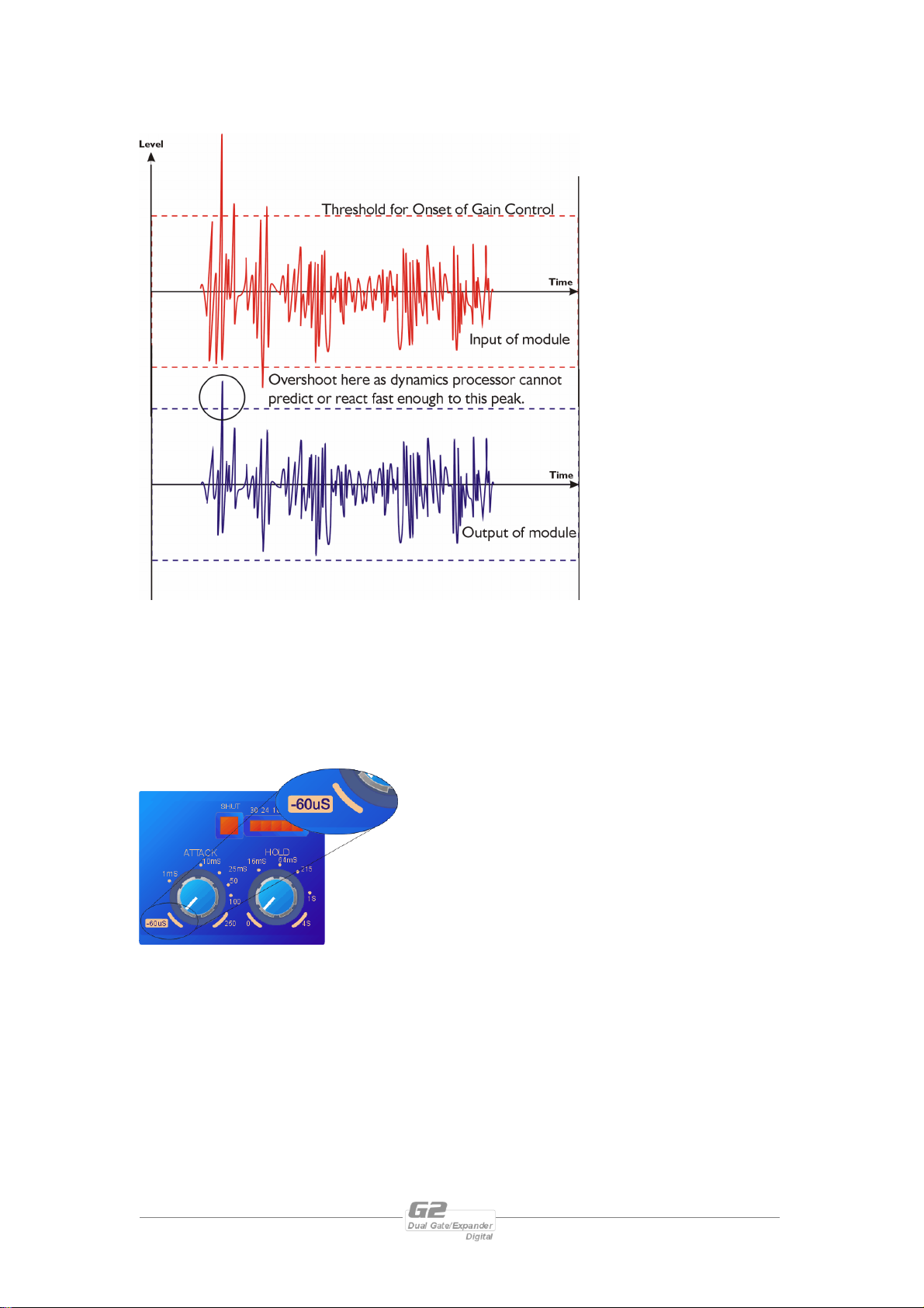
The red waveform
represents the input to
the dynamics module,
with the dotted line
showing the threshold
for gain control to occur.
There are several peaks
towards the start of this
signal that are above the
threshold, and so the
dynamics processing
should react to these as
appropriate. (In this case
reduce the gain).
The blue waveform
shows the output of the
dynamics module. The
circled peak
demonstrates that the
processor has missed the
first peak above the threshold (as it is very fast and short), but has ‘caught up’ shortly
afterwards, keeping all other peaks under control. As it is unable to predict what is
coming, this will always be a failing with analogue dynamics processing.
The G2’s ability to predelay the sidechain allows it to predict what will be appearing
in the main signal path and react before the signal arrives, thus preventing the
overshoot seen above.
Setting the attack time control to its minimum
setting will force the G2 to use predelay in the
sidechain. The effect of this is explained in the
next section.
Page 22 G2 Operators Manual
Page 23
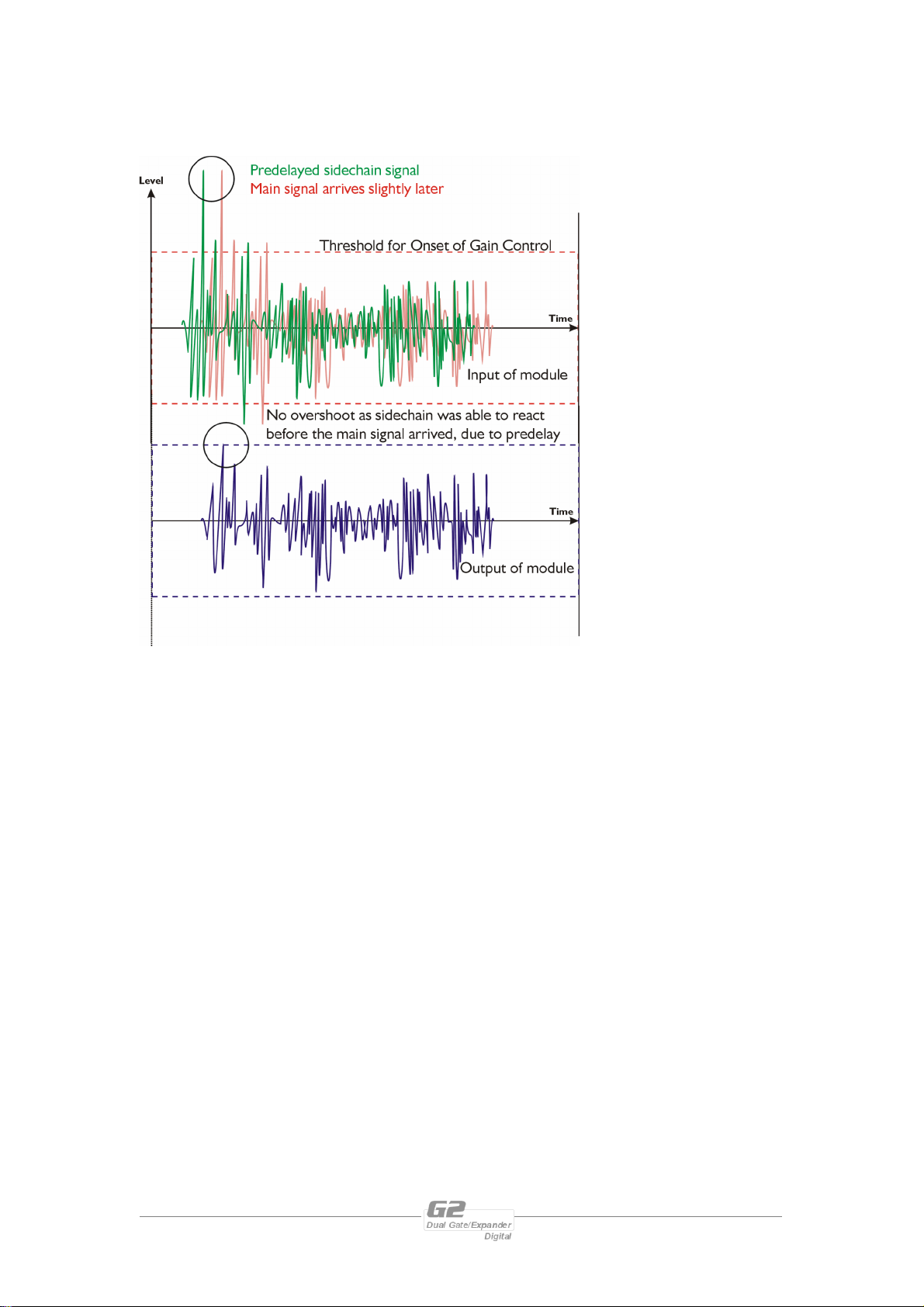
The predelayed
sidechain is shown in
green, with the main
signal in red.
As the main signal arrives
slightly after the
sidechain, the output
from the G2 does not
suffer from the
overshoot problem.
Remember that this delay is only in the order of 60uS,and is a predelay – the
sidechain is moved back in time in relation to the main signal. Inserting a delay into
the main signal path of an analogue dynamics processor will achieve similar results,
but with the penalty of delaying the main signal by the amount of look ahead delay
introduced.
Note that the G2 does not have to use this look ahead delay – in many cases, it is
preferable to allow a slower attack. For example, gating a human voice it is often
preferable to have an attack time in the order of 10mS to prevent the signal from
clicking due to the sudden change in level, and to preserve the natural envelope of the
voice.
G2 Operators Manual Page 23
Page 24
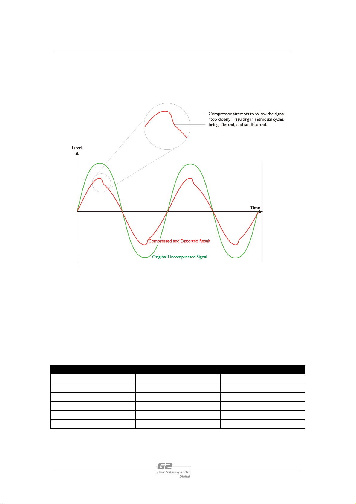
Setting the Attack and Release times
As with all dynamics processors too fast attack and release times on low frequency
program (such as a bass guitar) will cause the process to respond to individual cycles
of the signal, rather than the overall envelope. This will result in obvious distortion,
which might be described as sounding like clicking superimposed on the original
signal. This is illustrated with the example of a compressor being used on a bass guitar
signal below.
The gate release time has been deliberately restricted to a minimum of 25mS to
prevent excessive distortion on low frequency signals, even with fast attack times and
high range settings. None the less, it is still possible to introduce some distortion if
care is not taken with the settings. The best way to ensure that the signal is not being
excessively distorted is to make good use of the ‘ACTIVE’ button, constantly
comparing the original signal with the compressed version.
A general rule of thumb when setting the attack and release times would be to set
them sympathetically with the original signal’s envelope. Some basic settings are
given below.
Type of signal Attack Release
Human Voice 10mS 200mS
Bass Guitar 5mS (if plucked) Up to 500mS
Bass Drum -60uS – 1mS 50mS
Snare Drum -60uS Up to 150mS
Strings 150mS Up to 500mS
Brass 25mS 100mS
Page 24 G2 Operators Manual
Page 25
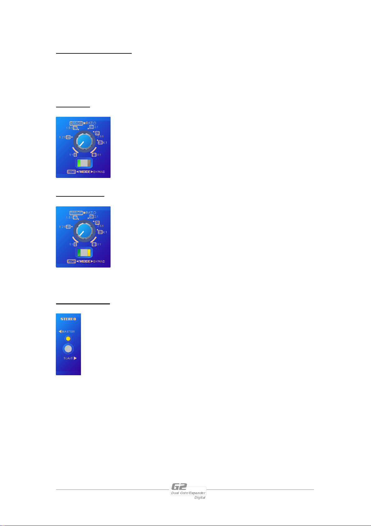
Gate and Expand MODE
Pressing and HOLDING the MODE key will change the operation of the channel
between gate and expand modes. The major differences between these are
explained below
Gate mode
In Gate mode, once the signal has dropped below the threshold,
it will be attenuated by a fixed amount, as set with the range
control. How fast this attenuation is applied is controlled by the
release control. The gate can be set to stay open for a fixed time
after dropping below the threshold –this is the hold time. How
fast the signal reaches zero attenuation again when it goes over
the threshold is determined by the attack control.
Expander mode
In Expander mode, once the signal has dropped below the
threshold, it will be gradually attenuated with a ratio as set with
the ration control. For example, if the ratio is set to 4:1, for
every dB the signal drops below the threshold, it will be
attenuated to a ¼ of its normal value.
How fast this attenuation is applied is controlled by the release
control. How fast the signal reaches zero attenuation again when
it goes over the threshold is determined by the attack control. The hold control has
no affect in expander mode.
STEREO Linking
Pressing and HOLDING the STEREO key will illuminate the LED and
gang the two channels of the unit together.
This has the effect of disabling the controls for channel B, as both channels
will assume the settings on channel A. Additionally, the sidechains will be
linked so that, if one channel opens so will the other, so avoiding any shifts
in the stereo image.
Metering remains independent between the two channels. Note that as soon as the
stereo linking is turned off, channel B will assume the parameters as set by its
controls. This might have a dramatic effect on the level of the channel, so be careful!
G2 Operators Manual Page 25
Page 26
Operating Notes
Operating Level
With any audio signal processing equipment it is necessary to ensure adequate signal
level is used through the device, to avoid sacrificing noise performance. It is suggested
that the operating level chosen should give adequate level to just light the +12dB
LED on the headroom meter with maximum program level being used. Since the
meter is deliberately set to show clipping 3dB early, this still provides 9dB of
headroom before clipping occurs. It should be noted that the figure quoted for the
maximum input level options is the clipping point for that option (not a safe operating
level). Always ensure that this clipping point is no lower than that for the following
equipment in the signal chain, and allow extra margin if equalisation sections are
boosted.
Grounding
The Screen (shield) pins on all audio connectors are normally connected directly to
the ground pin of the IEC mains inlet. The chassis is also directly connected to this
pin. Never operate this unit without the mains safety ground connected. Signal
ground (0V) is in turn connected to the chassis ground.
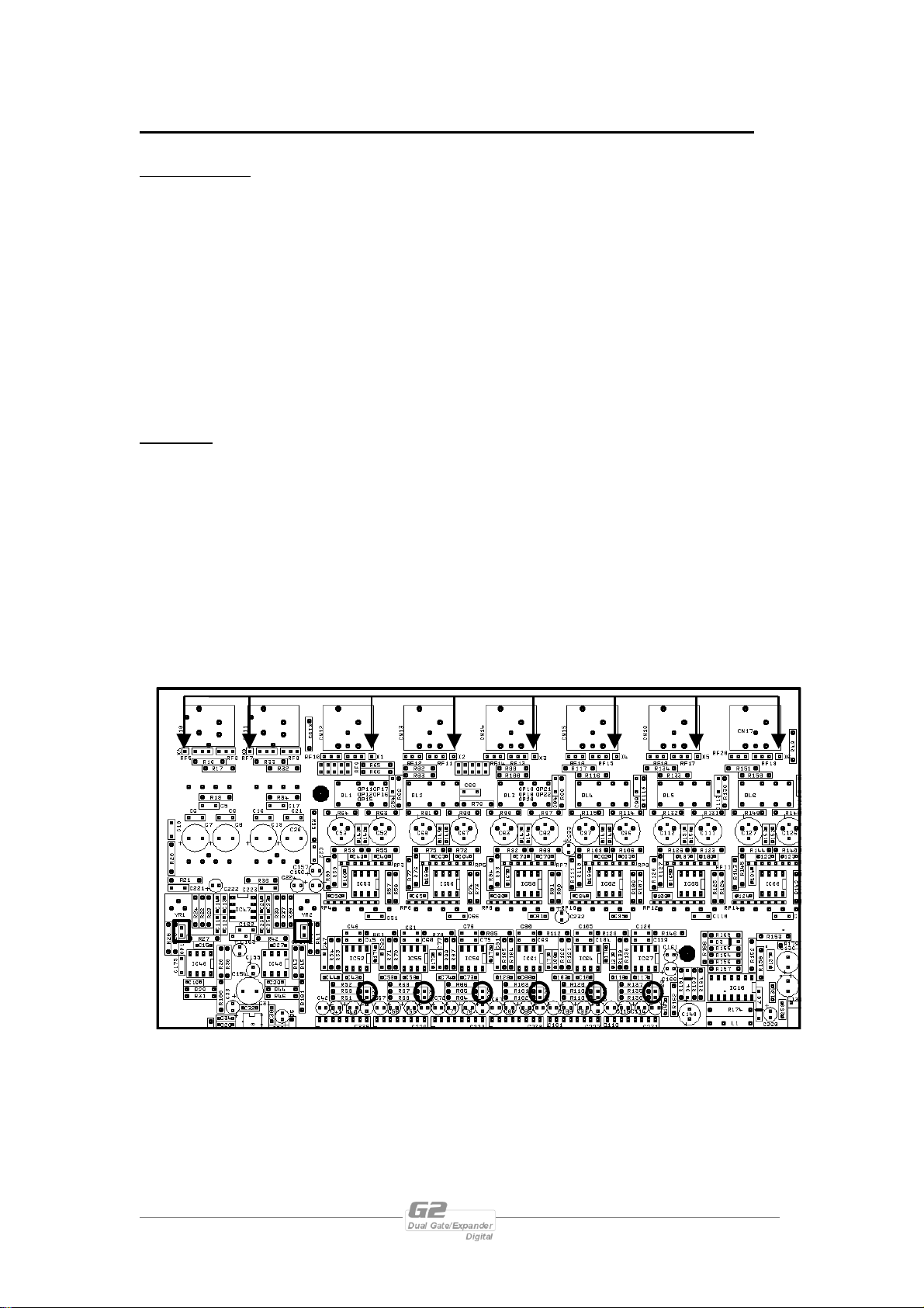
To avoid ground loops, cable shields should be connected to ground at one end only.
The normal convention is that the shield is only connected at the output XLR.
Provision is also made for separately isolating each input and output shield pin
permanently within the G2 by breaking the appropriate PCB track, where marked
with a box and an arrow next to each XLR connector using a small drill bit or cutter.
See the following diagram for details.
XLR pin 1 Isolation points (arrowed) and 10dB pads (circled)
Page 26 G2 Operators Manual
Page 27
Specifications
Inputs: 2 electronically balancedu
Impedance: > 10k ohms.
CMRR : >65dB 50Hz - 10kHz.
Outputs: 2 electronically balancedu
Source Imp: < 60ohms
Min. Load: 600ohm
Max. Level: +20dBm into 600 ohm
Frequency Resp.:+½dB 20Hz-20kHz
Dyn Range:>110dB 20Hz-20k unwtd
Distortion:< .02%@1kHz,+18dBm
Gate/Expander
Threshold: -40dBu to +22dBu
Range: 0 to 70dB
Ratio: 1:1 to 8:1
Attack: -60uS to 250mS
Hold: 0 to 4 S
Release: 25mS to 2 S
Sidechain EQ Section
High Pass Filter
Type: 12dB/Oct. Butterworth
Corner Freq: 10Hz to 5kHz
Low Pass Filter
Type: 12dB/Oct. Butterworth
Corner Freq: 250Hz to 22kHz
Parametric Section
Type: Selectable narrow (0.8
Oct.)/wide (1.43 Oct.) band-pass.
Centre Freq: 20Hz to 20k
Gain: +8,12 or 20dB and ‘Off’
Sidechain monitor available.
Input meter: 7 point:
-18dBu to +18dBu.
Threshold meter: 5 point:
-16, -8, 0, +8, +16dBr to threshold
setting
Gain Reduction meter: 7 point:
<6dB, 6, 12, 18, 24, 30, >40dB
Connectors
Inputs: 3 pin female XLR
Outputs: 3 pin male XLR.
Power: 3 pin IEC
Power: 60 to 250V ±15% @
50/60Hz.
Consumption: < 20 watts.
Weight : 3.5kg. Net (4.8kg.
Shipping)
Size: 1.75"(1U) x 19" x 11.8"
(44 x 482 x 300mm) excluding
connectors.
Options u = Transformers available.
Optional Interfaces AES/EBU Digital Input/Output
Due to continuing product improvement the above specifications are subject to change.
G2 Operators Manual Page 27
Page 28
Warranty
This product is warranted against defects in components and workmanship only, for a
period of one year from the date of shipment to the end user. During the warranty
period, XTA will, at it's discretion, either repair or replace products which prove to
be defective, provided that the product is returned, shipping prepaid, to an
authorised XTA service facility.
Defects caused by unauthorised modifications, misuse, negligence, act of God or
accident, or any use of this product that is not in accordance with the instructions
provided by XTA, are not covered by this warranty.
This warranty is exclusive and no other warranty is expressed or implied. XTA is not
liable for consequential damages.
Options and Accessories
Part Number Part Description
ITX-100
OTX-100
G2 Transformer balanced inputs (factory fitted only)
G2 Transformer balanced outputs (factory fitted only)
AES-G2 AES/EBU Digital inputs/outputs (factory fitted only)
Page 28 G2 Operators Manual
 Loading...