


Page 2 |
DP548 Operator’s Manual |

DP548 Quick Reference
Editing channels : press channel’s GAIN key. First press accesses that channel’s gain. To scroll through channel’s parameters, use the BACK and NEXT keys. Second press accesses last viewed parameter. Third press will drop back to the default screen.
Accessing menus: press the MENU key. Use the BACK and NEXT keys to select the sub-menu required, and enter the sub-menu using the ENTER key. This applies to all levels of menu. ENTER always confirms selections.
The Menus and their Contents
GLOBAL MEMORY Sub-menu: Recall/Store/Erase input, graphic EQ, dynamic EQ, and crossover settings, or combinations of these. INPUT SECTION Sub-menu: Set up input ganging, and GEQ ‘Q’ setting.
CROSSOVER Sub-menu: Set up or adjust crossover design, including routing and auto limiter setting. Also set up output ganging. INTERFACE Sub-menu: Comms interface setup (RS232 and RS485), G.P.I. interface configuration, and wireless interface.
SYSTEM Sub-menu: Used to view unit’s status, and select various global options such as PEQ ‘Q’ or bandwidth units, delay units, and output metering point (pre/post mute).
SECURITY Sub-menu: Used for locking various operations of the unit, using a 4 digit code.
AES/EBU Sub-menu: Switch outputs from analogue to digital and monitor AES input status info. (AES inputs are switched via rear panel.) DYNAMIC Sub-menu: Change how gain reduction meters behave.
Notes
The output meters show level, in dB from the limiter threshold, and the input meters show level from clipping the A-D converters,
pre-gain and all EQ.
When editing DEQ or compressors, meters read downwards and show gain reduction for each DEQ section or compressor respectively.
The high and low pass crossover filters are defined independently on each output channel.
To access the limiter attack and release parameters, select “AutoLimiter TimeCst: No” when designing a crossover.
To swap parametric filter units between bandwidth (‘BandW’) and ‘Q’, enter System Sub-menu, select ‘Filter Q / Bandwidth’, and select required readout units.
To swap delay time units, enter System Sub-menu, select ‘Delay
Time / Distance’, and select required readout units.
Pressing an EDIT key flashes corresponding channels routed to / from that channel.
DP548 Operator’s Manual |
Page 3 |

Contents
Important Safety Information |
6 |
Thanks |
7 |
Unpacking the unit |
7 |
Introduction |
8 |
Features |
8 |
Front Panel Familiarisation |
9 |
Rear Panel Connections |
10 |
Operating the DP548 |
11 |
Note about operation with AudioCore software. |
11 |
Start-up procedure |
11 |
Preliminary Set-up as a Crossover |
11 |
Input Channel Makeup |
12 |
Output Channel Makeup |
12 |
Preset Routing Configurations |
12 |
Free Assign Routing |
15 |
Full Matrix Mixing |
15 |
Editing Audio Parameters – Input Channels |
16 |
Input Gain |
16 |
Base Delay |
16 |
Input Graphic EQ |
16 |
Input Parametric EQ |
16 |
Editing Audio Parameters – Output Channels |
18 |
Output Gain |
18 |
Output Polarity |
18 |
Output Delay |
18 |
Output High Pass Filter |
19 |
Output Low Pass Filter |
19 |
Output Parametric EQ |
19 |
Output Compressor |
20 |
Output Limiter |
21 |
Output “D-Max” (Clip) Limiter |
21 |
Input Ganging and Output Ganging |
22 |
Menus in Detail |
24 |
Memory Structure |
26 |
Remote Control Interface Operation |
28 |
RS232 Interface |
28 |
RS232 Connection (Single Unit) |
28 |
Loading New Software via a PC |
29 |
RS232 Connection (Multiple Units) |
29 |
Shadow ID Numbers |
30 |
RS485 Connection |
31 |
Page 4 |
DP548 Operator’s Manual |
AES Inputs and Outputs |
33 |
AES Input |
33 |
AES Output |
33 |
AES Diagnostics and Status Information |
34 |
Security and Locking |
35 |
Entering the Password to Complete the Locking Operation |
35 |
Unlocking the Unit |
36 |
Forgotten the Password? |
36 |
PCMCIA Card and Compact Flash Card Usage |
37 |
Preset Library Updates via the card |
37 |
Unit Software Updates via the card |
37 |
Unit Cloning |
38 |
Copying Unit Software and Preset Files |
38 |
Copying Data from Source Unit |
38 |
Loading Data into Destination Unit |
38 |
Cold Start Reboot Procedure |
38 |
Advanced Audio Features |
39 |
Graphic Equaliser Behaviour |
39 |
The “GQ600” behaviour |
39 |
The “Special” behaviour |
40 |
What is Dynamic EQ? |
41 |
Quadrant/Mode I: “Boost Above” |
41 |
Uses of “Boost Above” mode. |
41 |
Uses of “Cut Above” mode. |
42 |
Uses of “Cut Below” mode. |
43 |
Uses of “Boost Below” mode. |
44 |
Dynamic EQ operating modes |
45 |
Parallel Mode |
45 |
Serial Mode |
45 |
Setting the Attack and Release times |
46 |
The Compressor ‘Knee’ Control |
47 |
Program Limiter and “D-Max” Limiter |
48 |
Program Limiter |
48 |
“D-Max” Clip Limiter |
49 |
Setting Accurate Limiter Thresholds |
51 |
Crossover Filter Slopes |
52 |
Time Alignment |
52 |
Parametric Filter Types and Their Uses |
53 |
Standard Parametric EQ |
53 |
Shelving EQ (High Shelf shown) |
54 |
Creating a Flat-topped EQ Response |
54 |
Notch Filter |
55 |
All Pass Filter |
56 |
Phase Filter |
56 |
Low/High Pass Variable ‘Q’ Filter (Low Pass shown) |
57 |
Elliptical filters |
58 |
Specifications |
59 |
Warranty |
60 |
Options and Accessories |
60 |
Index |
61 |
Operator’s Manual |
Page 5 |
An example of this equipment has been tested and found to comply with the following European and international Standards for Electromagnetic Compatibility and Electrical Safety:
Radiated Emissions (EU): |
EN55013-1 |
(1996) |
RF Immunity (EU): |
EN55103-2 |
(1996) RF Immunity, ESD, Burst Transient, Surge, Dips &Dwells |
Electrical Safety (EU): |
EN60065 (1993) |
|
Important Safety Information
Do not remove Covers.
No user serviceable parts inside, refer servicing to qualified service personnel.
This equipment must be earthed.
CAUTION
RISK OF ELECTRIC SHOCK
DO NOT OPEN
DO NOT EXPOSE TO RAIN, MOISTURE,
DRIPPING OR SPLASHING
ATTENTION
RISQUE DE CHOC ELECTRIQUE
NE PAS ENLEVER
NE PAS EXPOSER A LA PLUIE NI A L’HUMITE
Objects containing liquids, such as vases, must not be placed on this equipment.
It should not be necessary to remove any protective earth or signal cable shield connections.
Do not defeat the purpose of the polarized or grounding-type plug. A polarized plug has two blades with one wider than the other. A grounding type plug has two blades and a third grounding prong. The wider blade and the third prong are provided for your safety. When the provided plug does not fit into your outlet, consult an electrician for replacement of the obsolete outlet.
Only use this equipment with an appropriate mains cord.
In the USA the cord should comply with the requirements contained in the Standard for Cord Sets and Power Supply Cords, UL 817, be marked VW-1, and have an ampacity rating not less than the marked rating of the apparatus.
Page 6 |
DP548 Operator’s Manual |
Thanks
Thank you for choosing an XTA DP548 for your application. Please spend a little time reading through this manual, so that you obtain the best possible performance from the unit.
All XTA products are carefully designed and engineered for cutting-edge performance and world-class reliability. If you would like further information about this or any other XTA product, please contact us.
We look forward to hearing from you in the near future.
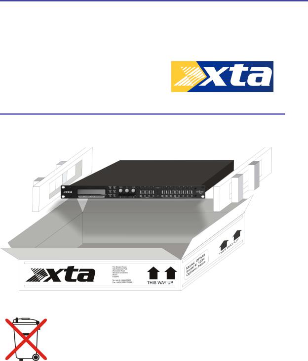
Unpacking the unit
After unpacking the unit, please check it carefully for any damage. If any is found, immediately notify the carrier concerned - you, the consignee, must instigate any claim. Please retain all packaging in case of future re-shipment.
Please think of our environment and don’t bin any materials, including this manual. When the product has reached the end of its useful life, please dispose of it responsibly through a recycling centre.
Operator’s Manual |
Page 7 |

Introduction
The DP548 is a powerful DSP based audio processor, where it combines the functions of a multitude of conventional products in a compact 1U unit with extensive remote control capabilities. To achieve this, the unit has four inputs and eight outputs which can be configured in a selection of basic crossover modes – 4 x 2 way; 2 x 3 way + 2 Aux; 2 x 4 way; and 1 x 8 way (as applicable to i/o configurations). They also offer a “free assign” mode, which allows completely flexible routing of any output from any combination of inputs and a “matrix” mode which allows mixing of any input to output (as opposed to switching with fixed gain).
Each input has a gain control, variable delay, a 28 band graphic equaliser and a further eight bands of fully parametric equalisation. The parametric filter bands have a large selection of different filter types available, including shelving, notch, band-pass, phase and elliptical behaviours. Three bands of dynamic EQ are also included on each input which adapts its behaviour depending of the proximity of the level to a user defined threshold.
Each output has a gain control, variable delay, high and low pass crossover filters, nine bands of fully parametric equalisation, polarity switching, a fully featured compressor with variable knee, a flexible limiter, and a final clip limiter. The crossover filters offer slopes of up to 48dB/Octave., with a variety of responses available.
Remote control1 is catered for in the form of RS232 and RS485 ports, and multiple user memories are provided for the storage and recall of settings. A GPI interface may also be fitted to allow remote memory recalls using simple switch closure apparatus.
Security lock-out is available for all controls.
The DP548 is also equipped with AES/EBU digital inputs and outputs, and include a sample rate converter, capable of accepting anything from 32kHz up to 192kHz.
Units may be controlled externally by XTA’s proprietary |
WindowsTM software, along with existing and |
future ‘AudioCore’ products. |
|
Features
Superb audio quality – carefully optimised double precision signal processing coupled with 24 bit conversion ensure a dynamic range in excess of 117dB. The high sampling rate of 96kHz means minimal filtering providing exceptional sonic purity with a bandwidth in excess of 32kHz.
A flexible input/output multi-mode format caters for any configuration, regardless of scale. Both routing of inputs to outputs, and ganging (for editing) are completely flexible.
A completely new SHARCTM based DSP platform supplies phenomenal computational power, allowing the unit to provide not only multiple bands of standard parametric equalisation on every input and output, but also a full spectrum graphic equaliser on each of the four inputs. Three bands of dynamic EQ are available on each input, along with a fully featured soft-knee compressor, program limiter and look-ahead clip limiter on each output.
Delay of up to 650mS may be independently set for each output, with an exceptionally fine minimum increment of 300nS, which corresponds to a distance change of 0.1mm!
The comprehensive standard specification also includes up to 255 memories, and remote control via RS232 or RS485 ports, with security lockout.
1 Note that only the RS232 and RS485 interfaces offer full remote control of this product – the GPI interface may only be used for memory recall (program change) purposes.
Page 8 |
DP548 Operator’s Manual |
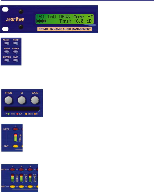
Front Panel Familiarisation
LCD Screen: Shows, by default, the name of the last recalled memory on the bottom line of the screen, and the current routing on the top line. Also used to show all parameters as they are edited, and all menu selections.
Control Keys: Selection and adjustment of parameters. NEXT key moves forward through list of parameters. BACK key moves backwards through list of parameters.
MENU key activates the main menu – a second press selects the last menu edited – a third press selects the last menu item. In this way, three presses on MENU from the default screen will jump back to the last parameter adjusted. Selection of different menus is accomplished using the BACK and NEXT keys, or with the FREQ encoder.
ENTER key enters the chosen menu, confirms selections, and changes filter types when editing parametric sections.
BYPASS will flatten the currently selected parametric sections, or input graphic equalisers and dynamics modules. For safety reasons, it is not possible to bypass the high and low pass filter sections. QUIT exits menus back to the default screen.
Rotary Encoders: Three velocity sensitive encoders adjust the relevant parameters as displayed on the screen.
Memory Card Slot: Will accept type I or type II PCMCIA SRAM cards and, using an adapter, Compact Flash cards. This allows the unit to be cloned, memory sets saved, presets loaded, and firmware updates installed.
Status LEDs: The four status LEDs show, from left to right, AES inputs selected (flashing if not locked); AES outputs selected; Comms activity (only illuminates on messages addressed to this particular unit); and a general-purpose spare indicator.
Input Sections: Control and monitor input signal paths.
Red MUTE buttons illuminate when pressed and mute audio for that channel.
EDIT buttons illuminate yellow when pressed, and access gain on first press, then last viewed parameter on second press, then exit on third press.
Input meters show dB from clipping point of the analogue to digital converters. Yellow (0dB) LED illuminates 3dB from clipping. Red CLIP LED may illuminate independently from the rest of the meter to show digital overflow. All four CLIP LEDs illuminating indicates internal clipping after the ADC. Meters also read downwards from the yellow LED to show gain adjustment (reduction or expansion) when editing DEQ modules – meter shows gain adjustment for current band of DEQ only.
Output Sections: Control and monitor output signal paths.
Red MUTE buttons illuminate when pressed and mute audio for that channel.
EDIT buttons illuminate yellow when pressed, and access gain on first press, then last viewed parameter on second press, then exit on third press. Output meters show dB from limiting. The yellow LED illuminates at the onset of limiting. The red LED illuminates at 4dB into limiting (i.e. 4dB of gain reduction).
Meters also read downwards from the yellow LED to show gain reduction when editing compressors. These may be left permanently enabled by changing this option in the DYNAMICS sub-menu.
Operator’s Manual |
Page 9 |
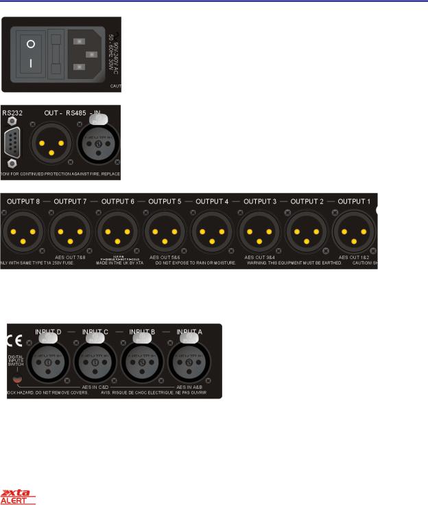
Rear Panel Connections
Power Switch: turns the unit’s mains supply off and on.
Mains Fuse: located in a finger-proof holder adjacent to the mains inlet. A spare fuse is also located in this holder.
Mains Inlet: connected via a standard IEC socket.
RS232: RS232 standard via a 9 pin D-type connector, for connection to a PC. Data is converted to RS485 standard and relayed to slave units via the RS485 sockets.
RS485 In-Out: XLR sockets. Used for transmission of remote control data over long distance or multiple unit applications. See page 30 for more information.
For more details on interfaces see our Interface Guide, available from the website.
Audio Outputs: 3 pin XLR sockets are provided for each channel. All are fully balanced, pin 2 hot, 3 cold, 1 screen. Note the legending on the panel to designate which outputs are used for AES streams when the digital outputs are enabled. Please see page 33 for more information.
AES Input Switch: Recessed switch to select AES digital inputs. Red LED will illuminate in the hole when AES inputs are selected, along with the corresponding front panel indicator.
Audio Inputs: 3 pin XLR sockets are provided for each channel. All are fully balanced, pin 2 hot, 3 cold, 1 screen.
Note the legending on the panel to designate which inputs are used for AES when the digital inputs are enabled. Please see page 33 for more information.
Always replace the fuse with the correct type and rating as shown on the rear panel legend.
Page 10 |
DP548 Operator’s Manual |
Operating the DP548
Note about operation with AudioCore software.
The following operating information covers setup and control of the DP548 via the front panel controls only. Please consult the manual supplied with this software for information regarding full computer control.
Start-up procedure
Switching on the unit will display a brief message detailing the unit type and software version running
== AudioCore DP548 ==
==Software V 1.00 ==
and all LEDs will briefly illuminate. The unit will then begin its countdown to the wake-up procedure2, during which time the audio will fade up to the level last set. Metering will begin to operate when the fade-up starts.
Preliminary Set-up as a Crossover
The procedure below should be followed when first installing a DP548.
Design your crossover! To do this, press MENU, and use the BACK or NEXT key to select ‘Crossover
sub-menu’ and then press ENTER. Use the BACK or NEXT key to select ‘Design a crossover’ and then press ENTER. Finally, use the BACK or NEXT key to select the desired routing3and follow the set-up wizard to finalise your design.
Note that when in a menu, ENTER is always used to confirm selections. The current selection is marked with an asterisk ‘*’.
Use the EDIT keys on each output channel with the BACK and NEXT keys to select the high pass filters, low pass filters, parametrics etc. Note that when designing a new crossover, the high and low pass filters will be set to default values.
Use the EDIT keys on each input channel with the BACK and NEXT keys to select the gain, delay and parametrics available on each input.
Note that if no action is taken in menu mode, the unit will return to normal ‘default’ mode after about twenty (20) seconds. Repeat the above directions to return to menu mode.
2 |
The wake-up time countdown may be adjusted in the SYSTEM menu – see page 24 for details. |
|
3 |
For details about adjusting the routing if one of the standard configurations does not suit, see page 15. |
|
|
Operator’s Manual |
Page 11 |
Routing Options and Processing Blocks
Due to the completely new DSP platform, the routing possibilities within the DP548 have been made completely flexible, with a matrix available allowing any combination of inputs to be routed to any output. The additional DSP power has permitted the inclusion of more processing blocks, even considering the extra inputs and outputs, and the doubling of sample rate.
To reduce set-up time and aid usability, several standard configurations are available as described in a later section.
This section will outline the processing blocks available in relation to the signal path, and explain the various options for routing, including the “Free Assign” mode, which opens up completely flexible channel routing, and “Matrix” mode which also adds gain controls for mixing capabilities.
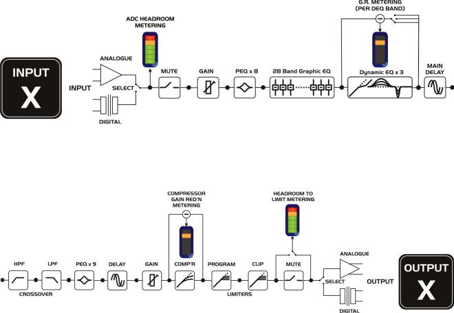
Input Channel Makeup
The diagram below shows the processing available on each of the four input channels, before routing to the matrix.
Output Channel Makeup
The diagram below shows the processing available on each of the eight output channels, after routing from the matrix/mixer.
Preset Routing Configurations
In addition to the ability to assign any combination of inputs to any output, a number of preset configurations are provided, for use when designing a crossover from scratch. These have the advantage of suggested settings for the high and low pass filters to useful basic starting points, to filter the different outputs as appropriate for the chosen configuration. These may, of course, be freely modified afterwards should they not suit the requirements exactly.
The diagrams on the following pages show the connections made between inputs and outputs, and the suggested values chosen for the high and low pass filters.
Page 12 |
DP548 Operator’s Manual |

4 x 2 way crossover: As shown, each input feeds a pair of outputs, odd numbers being the low frequency split, and even numbers being the high part of the spectrum. Default suggested crossover frequencies are shown by each output.
2 x 3 way crossover: Inputs A and B feed three outputs each, with output 7 being fed from input C, and output 8 from input D. Note the ‘Aux’ outputs are set to full range. Default suggested crossover frequencies are shown by each output.
Operator’s Manual |
Page 13 |

2 x 4 way crossover: Inputs A and B feed four outputs each, with inputs C & D being unused. Default suggested crossover frequencies are shown by each output.
1 x 8 way crossover: Inputs A is fed to all eight outputs, with initial settings being all full bandwidth. The crossover points can be adjusted as desired.
Page 14 |
DP548 Operator’s Manual |

Free Assign Routing
If none of the preset configurations are appropriate to the required system setup, it is possible to manually select the routing of the crossover. This is achieved through the Crossover Menu -> Design A Crossover.
Pressing ENTER will start the crossover design wizard, with the first option being to choose the routing.
The display will show
Design A Crossover ->
Routing = 2 X 4 WAY *
or whatever the current configuration is set to. Press BACK until the display shows
Design A Crossover ->
Routing = Free Assign
And then press ENTER. The EDIT key will illuminate for output 1, as will any relevant input EDIT keys, showing which inputs are feeding output 1. The display will also detail the current combination of inputs feeding this output. To change the routing for any output, press its EDIT key, and then choose the required input channel combination by just pressing the input EDIT keys as appropriate. The input combinations can also be stepped through in turn by pressing NEXT, or
BACK.
To complete the procedure, press ENTER. The wizard will continue, and if the routing has been changed, all outputs will be muted on exit.
Full Matrix Mixing
If the free assign mode still isn’t flexible enough (!), it is possible to manually select the routing of the crossover with full level mixing from any input to output. This is achieved through the
Crossover Menu -> Design A Crossover
Pressing ENTER will start the crossover design wizard, with the first option being to choose the current routing.
The display will show
Design A Crossover ->
Routing = 2 X 4 WAY *
or whatever the current configuration is set to. Press BACK until the display shows
Design A Crossover ->
Routing = Full Matrix
To complete the procedure, press ENTER. The wizard will continue, and if the routing has been changed, all outputs will be muted on exit.
Matrix routing levels are stored in crossover memories (as with routing settings).
Operator’s Manual |
Page 15 |

Editing Audio Parameters – Input Channels
Input Gain
The range of the control over the input gain is –40dB to +6dB in 0.1dB steps.
InA |
Input |
A |
Gain |
Input |
Gain |
= |
+6.0dB |
Gain
Base Delay
The maximum available delay between any input and output is 650.00mS. For example, if the input delay on channel A is set to 500mS, the maximum available output delay for any output fed from input A will be 150mS. The readout units can be changed between time in milliseconds, distance in feet or distance in metres. Please see page 24 for more details.
InA |
Input |
A |
Delay |
Base |
Delay |
= |
0.00mS |
x 1mS |
x 10uS |
343mm |
4mm |
Note that Base Delay (Input Delay) is not available when in “Full Matrix” mode.
Input Graphic EQ
The graphic equaliser has 28 third octave bands from 31Hz to 16kHz, and a gain range of +12dB. The G6 on the second line of the screen denotes the ‘Q’ behaviour of the graphic – this setting behaves like a GQ600 with variable ‘Q’ that is ‘gentler’ at low cut/boost values and sharpens at high cut/boost values. The alternate setting, Sp, is a constant ‘Q’ behaviour where no change in bandwidth occurs with differing cut/boost. Pressing BYPASS will bypass the entire Graphic EQ on this channel. For details of how to select the behaviour, please see page 24.
InA |
Input |
A |
Graph<> |
40Hz |
+----- |
G6 |
0.0dB |
Frequency |
Gain |
Input Parametric EQ
There are eight bands of parameter equalisation available on every input. The behaviour of each individual band can be changed to a variety of different filter shapes, including high and low shelves, notch, and bandpass. Changing the filter type is achieved by pressing ENTER during editing any particular band. For more details about the various types of filter available, please see page 51.
InA |
Input A |
PEQ:1<> |
|
1k00Hz |
Q=3.0 |
0.0dB |
|
Frequency ‘Q’ |
Gain |
Page 16 |
DP548 Operator’s Manual |
Input Dynamic EQ
There are 3 bands of dynamic EQ available on each input. Each band has three screens associated with it. For more information on how the dynamic EQ works, please see page 41. The first edit screen shows the threshold for the band, and the ratio for the dynamic action, along with the mode. The gain reduction meter to the left on the bottom line of the display shows gain reduction (or expansion) in 0.5dB steps. The band can by bypassed by pressing the BYPASS key whereupon the meter will be replaced by BYPASS.
InA |
Input A |
DEQ:1+^ |
|||||||||| Th=-32.0 |
Rat=2.00 |
|
Threshold Ratio
Mode is indicated at the right hand side of the top line like this “DEQ:1+↑”. In this case it represents “Boost Above” mode. The plus or minus shows boost or cut and the arrow shows above or below the threshold (↓). Mode is changed by setting the ratio to 1:1 and then pressing ENTER to scroll through the modes.
Pressing NEXT shows the attack and release times. Note that release time cannot be set to faster than the attack time and will be forced to track it if you increase the attack to a greater value than the release. This is to prevent introducing distortion that can be caused due to the detector tracking individual cycles of the waveform, rather than its envelope. For more information about this, see the section about the compressors on page NN.
InA |
Input A |
DEQ:1+^ |
|
At=0.07mS |
Rl=11mS |
Attack Release
Pressing NEXT shows the filter parameters for the band. Note that gain value shown is the maximum (or minimum) allowable amount of gain change that may be applied – so even if the signal is far over the threshold with a high ratio, the gain of the band won’t change by more than this value.
InA |
Input A |
DEQ:1+^ |
|
|
99.2Hz |
1.0 |
12dB |
Frequency |
‘Q’ |
Max. Gain |
Operator’s Manual |
Page 17 |

Editing Audio Parameters – Output Channels
Output Gain
The range of the control over the input gain is –40dB to +15dB in 0.1dB steps.
OP1 |
Output |
1 |
Gain |
Output |
Gain |
= |
+6.0dB |
Gain
Output Polarity
The polarity (or phase) of each output may be switched individually as below.
OP1 |
Output |
1 |
Polar. |
|
Polarity |
= |
[+] |
- or +
Output Delay
The maximum available delay between any input and output is 650.00mS. For example, if the input delay on channel A is set to 500mS, the maximum available output delay for any output fed from input A will be 150mS. The readout units can be changed between time in milliseconds, distance in feet or distance in metres. Please see page 24 for more details.
OP1 |
Output 1 |
Delay |
|
Delay = 0.0000mS |
|
x 1mS |
x 10uS |
x0.3uS |
343mm |
4mm |
0.1mm |
Page 18 |
DP548 Operator’s Manual |

Output High Pass Filter
The high pass crossover filter on each output has a frequency range of <10Hz up to 32kHz in 1/36th Octave steps. If you try to set the high pass filter to a higher frequency than the low pass (which would be pointless and result in no output), the message High/Low Freq. Overlap! will be displayed. Note that to access the 48dB/Octave filters, parametric bands 6 & 7 need to be bypassed, or set to 0dB. If they are not, the message Bypass PEQ’s 6 &
7 To Access 48dB Slopes will be displayed.
OP1 |
Output 1 HPF /~~ |
<10Hz |
Linkw-Riley 48dB |
Frequency Slope
Output Low Pass Filter
The low pass crossover filter on each output has a frequency range of 35.1Hz up to >32kHz in 1/36th Octave steps. If you try to set the low pass filter to a lower frequency than the high pass (which would be pointless and result in no output), the message High/Low Freq. Overlap! will be displayed. Note that to access the 48dB/Octave filters, parametric bands 8 & 9 need to be bypassed, or set to 0dB. If they are not, the message Bypass PEQ’s 8 &
9 To Access 48dB Slopes will be displayed.
OP1 |
Output 1 LPF ~~\ |
>32kHz |
Linkw-Riley 48dB |
Frequency Slope
Output Parametric EQ
There are nine bands of parametric equalisation available on every output4. The behaviour of each individual band can be changed to a variety of different filter shapes, including high and low shelves, notch, and bandpass. Changing the filter type is achieved by pressing BYPASS to bypass the filter and then pressing ENTER during editing any particular band. For more details about the various types of filter available, please see page 51.
OP1 |
Output 1 |
PEQ:1<> |
|
1k00Hz |
Q=3.0 |
0.0dB |
|
Frequency ‘Q’ |
Gain |
4 Note that 2 bands each will be lost when using 48dB slope crossover filters, resulting in a maximum of 5 bands of EQ when both high and low pass are set to 48dB/Octave.
Operator’s Manual Page 19
 Loading...