

Page 1
Tel: 01299 879977 (Intl. +44 1299 879977)
Fax: 01299 879969 (Intl. +44 1299 879969)
ta
Operator’s Manual Revision 1.10
DC1048
XTA Electronics Ltd.
The Design House,
Vale Business Park,
Worcester Road,
Stourport-on-Severn,
Worcs. DY13 9BZ.
England
Web: http://www.xta.co.uk
x
© XTA Electronics Ltd 2012
First published 01/2010
If you have any comments or suggestions about this manual, please
contact XTA at the address above, or email info@xta.co.uk
Operator’s Manual
DC1048 Integrated Audio Management
Page 1
Page 2

Page 2
DC1048 Integrated Audio Management
Operator’s Manual
Page 3

Contents
DECLARATION OF CONFORMITY .................................................................... 6
Important Safety Instructions ........................................................................... 7
Instructions De Securite Importantes ............................................................ 8
Thanks ............................................................................................................................ 9
Unpacking the unit .................................................................................................... 9
Introduction ................................................................................................................ 10
Installation .................................................................................................................... 11
Operation ...................................................................................................................... 12
Front Panel Indicators ........................................................................................... 13
1: “System” Menu Button .................................................................................................................................... 13
2: “GPI” Menu Button ........................................................................................................................................... 13
3: “Comms” Menu Button ................................................................................................................................... 13
4: Input Metering .................................................................................................................................................... 13
5: LCD Status Display .......................................................................................................................................... 13
6: USB Connector.................................................................................................................................................. 14
7: Output Metering ............................................................................................................................................... 14
8: Preset Selection Buttons ............................................................................................................................. 14
Rear Panel Controls, Connections and Indicators .................................. 15
1: Mains Power Inlet and Power Switch ...................................................................................................... 15
2: RS485 Connection .......................................................................................................................................... 15
3: GPI Port .................................................................................................................................................................. 15
4: Balanced Audio Outputs ............................................................................................................................... 15
Operator’s Manual
DC1048 Integrated Audio Management
Page 3
Page 4

Menus ............................................................................................................................ 16
Overview
.......................................................................................................................................16
Remote Control and Initial Set-up .................................................................... 17
Overview ....................................................................................................................................... 17
Direct USB Connection ........................................................................................................... 17
Layout of the Main Window............................................................................................................................... 21
DC1048 “Front Panel” Controls, Readouts and Indicators ............................................................ 27
Timed Presets and Preset Files ........................................................................................................................ 31
Connection of Multiple Units on an RS485 Network ........................................... 34
Connection via front panel USB and break-in to the RS485 Network .................................... 34
Connection directly to the RS485 Network ........................................................................................... 35
Security and Locking ............................................................................................ 37
Overview ..................................................................................................................................... 37
Local Front Panel Locking ................................................................................................................................. 37
Forgotten the PIN? ............................................................................................................................................... 37
Security in ICORE ............................................................................................................................................ 38
The GPI Port ............................................................................................................. 40
Overview .................................................................................................................................... 40
Isolated Connection ............................................................................................................................................. 40
Non-Isolated Connection .................................................................................................................................... 41
Simple Mode .............................................................................................................................................................. 41
Complex Mode ......................................................................................................................................................... 42
Panel Mode ............................................................................................................................................................... 42
Page 4
DC1048 Integrated Audio Management
Operator’s Manual
Page 5

Appendix I: Updating Device Firmware.......................................................43
Overview ..................................................................................................................................... 43
Update Procedure Using ICORE ............................................................................................................. 43
Appendix II: Limiter Types and Setting Thresholds ............................. 45
Program Limiter and “D-Max” Limiter .......................................................................... 45
Program Limiter ..................................................................................................................................................... 45
“D-Max” Clip Limiter ............................................................................................................................................ 46
Appendix III: Parametric Filter Types and Their Uses ........................ 50
Standard Parametric EQ .................................................................................................................................. 50
Shelving EQ (High Shelf shown) .................................................................................................................... 51
Creating a Flat-topped EQ Response............................................................................................................ 51
Notch Filter ............................................................................................................................................................... 52
All Pass Filter .......................................................................................................................................................... 53
Phase Filter ............................................................................................................................................................... 53
Low/High Pass Variable ‘Q’ Filter (Low Pass shown) ..................................................................... 54
Elliptical filters ........................................................................................................................................................ 55
Appendix IV: Maintenance ............................................................................... 56
Appendix V: Specifications ............................................................................... 57
Index ............................................................................................................................. 59
Operator’s Manual
DC1048 Integrated Audio Management
Page 5
Page 6
DECLARATION OF CONFORMITY
ta
x
We, the manufacturer:
XTA Electronics Ltd.,
The Design House,
Vale Business Park,
Worcester Road,
Stourport on Severn,
Worcestershire,
England
DY13 9BZ
acknowledge our responsibility that the following product:
Kind of equipment: Audio processor
Commodity Code: 8518408990
Type Designation: DC1048
is manufactured:
in accordance with EMC Directive 2004/108/EC,
in compliance with the following norm(s) or document(s):
Technical Regulations: EN55103-1:1996, EN55103-2:1996
and
in accordance with the Low Voltage Directive 2006/95/EC,
in compliance with the following norm(s) or document(s):
Technical Regulations: EN/IEC60065:2002 7th Edition
Signed: …………………………………………………………………
Name: Alex Cooper
Position: Research and Development Manager
Date: January 2012
Page 6
DC1048 Integrated Audio Management
Operator’s Manual
Page 7

Important Safety Instructions
CAUTION: RISK OF ELECTRIC SHOCK.
DO NOT OPEN
The lightning flash with arrowhead
symbol within an equilateral triangle
is intended to alert the user to the
presence if uninsulated “dangerous
voltage” within the product’s
enclosure that may be of sufficient
magnitude to constitute a risk of
electric shock to persons.
WARNING: Apparatus with CLASS I construction shall be connected to a MAINS socket outlet with a
protective earthing connection.
WARNING: To prevent injury, this apparatus must be securely attached to the rack in accordance
with the installation instructions.
1. Read these instructions.
2. Keep these instructions.
3. Heed all warnings.
4. Follow all instructions.
5. Do not use this apparatus near water.
6. Clean only with a dry cloth.
7. Do not block any ventilation openings,
install in accordance with the manufacturer’s
instructions.
8. Do not install near any heat sources, such
as radiators, heat registers, stoves or other
apparatus (including amplifiers) that produce
heat.
9. Do not defeat the safety purpose of the
polarized or grounding-type plug. A polarized
plug has two blades with one wider than the
other. A grounding-type plug has two blades
and a third grounding prong. The wide blade or
the third prong are provided for your safety. If
the provided plug does not fi t into your outlet,
consult an electrician for replacement of the
obsolete outlet.
10. Protect the power cord from being walked
on or pinched particularly at plugs,
convenience receptacles and the point where
they exit from the apparatus.
11. Only use attachments/accessories
specified by the manufacturer.
The exclamation point within an
equilateral triangle is intended to
alert the user of important
operating and maintenance
(servicing) instructions in the
literature accompanying the
appliance.
12. Use only with the cart, tripod, bracket or
table specified by the manufacturer, or sold with
the apparatus. When a cart is used, use caution
when moving the cart/apparatus combination to
avoid injury from a tip over.
13. Unplug this apparatus during lightning
storms or when unused for a long period of time.
14. Refer all servicing to qualified service
personnel. Servicing is required when the
apparatus has been damaged in any way, such
as if the power-supply cord or plug is damaged,
liquid has been spilled or objects have fallen into
the apparatus, the apparatus has been exposed
to rain or moisture, does not operate normally,
or has been dropped.
15. Do not expose this equipment to dripping or
splashing and ensure that no objects filled with
liquids, such as vases, are placed on the
equipment.
16. To completely disconnect this equipment
from the AC mains, disconnect the power cord
from the mains circuit breaker.
17. This unit is fitted with a 3-wire power cord.
For safety reasons, THE EARTH LEAD SHOULD
NOT BE DISCONNECTED IN ANY
CIRCUMSTANCE.
Operator’s Manual
DC1048 Integrated Audio Management
Page 7
Page 8

Instructions De Securite Importantes
ATTENTION: RISQUE DE CHOC ELECTRIQUE.
NE PAS OUVRIR
Le symbole représentant un éclair fléché
dans un triangle équilatéral a pour but
d’alerter l’utilisateur de la présence d’une
“tension dangeruese” non isolée à l’intérieur
du boitier, pouvant être d’une force
suffisante pour constituer un risqué
d’électrocution.
ATTENTION: Appareils de construction de CLASSE I doit être raccordé au réseau électrique via une
prise de courant reliée à la terre.
ATTENTION: Pour éviter toute blessure, cet appareil doit être solidement fixé à la torture,
conformément aux instructions d'installation.
1. Lisez ces consignes.
2. Conservez ces consignes.
3. Respectez tous les avertissements.
4. Respectez toutes les consignes d’utilisation.
5. N’utilisez jamais l’appareil à proximité d’un
liquide.
6. Nettoyez l’appareil avec un chiff on sec.
7. Veillez à ne pas empêcher la bonne
ventilation de l’appareil via ses ouïes de
ventilation. Respectez les consignes du
fabricant concernant l’installation de l’appareil.
8. Ne placez pas l’appareil à proximité d’une
source de chaleur telle qu’un chauff age, une
cuisinière ou tout appareil dégageant de la
chaleur (y compris un ampli de puissance).
9. Ne supprimez jamais la sécurité des prises
bipolaires ou des prises terre. Les prises
bipolaires possèdent deux contacts de largeur
diff érente. Le plus large est le contact de
sécurité. Les prises terre possèdent deux
contacts plus une mise à la terre servant de
sécurité. Si la prise du bloc d’alimentation ou
du cordon d’ali-mentation fourni ne correspond
pas à celles de votre installation électrique,
faites appel à un électricien pour eff ectuer le
changement de prise.
10. Installez le cordon d’alimentation de telle
façon que personne ne puisse marcher dessus
et qu’il soit protégé d’arêtes coupantes.
Assurez-vous que le cordon d’alimentation est
suffisamment protégé, notamment au niveau
de sa prise électrique et de l’endroit où il est
relié à l’appareil; cela est également valable
pour une éventuelle rallonge électrique.
11. Utilisez exclusivement des accessoires et des
appareils supplémentaires recommandés par le
fabricant.
12. Utilisez exclusivement des chariots, des
diables, des présentoirs, des pieds et des
surfaces de travail recommandés par le fabricant
ou livrés avec le produit. Déplacez
précautionneusement tout chariot ou diable
chargé pour éviter d’éventuelles blessures en cas
de chute.
13. Débranchez l’appareil de la tension secteur
en cas d’orage ou si l’appareil reste inutilisé
pendant une longue période de temps.
14. Les travaux d’entretien de l’appareil doivent
être eff ectués uniquement par du personnel
qualifié. Aucun entretien n’est nécessaire sauf si
l’appareil est endommagé de quelque façon que
ce soit (dommages sur le cordon d’alimentation
ou la prise par exemple), si un liquide ou un
objet a pénétré à l’intérieur du châssis, si
l’appareil a été exposé à la pluie ou à l’humidité,
s’il ne fonctionne pas correctement ou à la suite
d’une chute.
15. N'exposez pas cet équipement au fait de
tomber goutte à goutte ou au fait d'éclabousser
et garantissez qu'aucun objet rempli des liquides,
comme les vases, n'est placé sur l'équipement.
16. Pour complètement débrancher cet
équipement de la conduite principale de courant
alternatif, débranchez la corde de pouvoir du
disjoncteur de conduite principale.
17. Cette unité est correspondue avec une corde
de pouvoir de 3 fils. Pour les raisons de sécurité,
L'AVANCE DE TERRE NE DEVRAIT ÊTRE
DÉBRANCHÉE DANS AUCUNE CIRCONSTANCE.
Le point d’exclamation dans un triangle
équilatéral a pour but d’alerter l’untilisateur
de la présence d’instructions importantes
concernant le fonctionnement et la
maintenance, dans la documentation qui
accompagne l’appariel.
Page 8
DC1048 Integrated Audio Management
Operator’s Manual
Page 9
Thanks
ta
x
THIS WAY UP
Stourpo rt on Seve rn
Thank you for choosing a DC1048 for your application. Please spend a little time
reading through this manual, so that you obtain the best possible performance
from the unit.
All XTA products are carefully designed and engineered for cutting-edge
performance and world-class reliability. If you would like further information
about this or any other XTA product, please contact us.
We look forward to hearing from you in the near future.
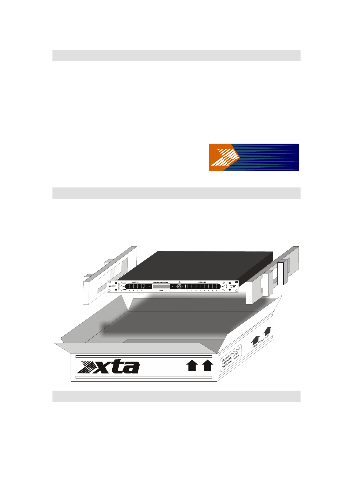
Unpacking the unit
After unpacking, please check the unit carefully for any damage. If any is found,
immediately notify the carrier concerned - you, the consignee, must instigate any
claim. Please retain all packaging in case of future re-shipment.
The Desi gn House
Vale Busin ess Park
Worcester Road
Worcs.
England
Tel +44 (0) 1 299 8799 77
Fax +44( 0) 1299 8799969
Operator’s Manual
DC1048 Integrated Audio Management
Page 9
Page 10
Introduction
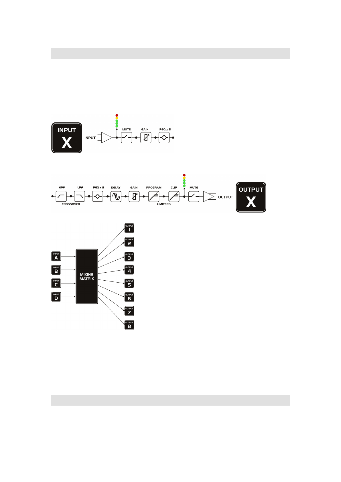
Your DC1048 is a 4 input, 8 output audio processor, offering a selection of flexible
features to configure and manage an installation audio system. These include
matrix mixing of all inputs to outputs, input equalisation, output equalisation,
output (speaker) crossovers, delays and speaker protection (limiters).
Input signal path:
Output signal path:
Each of the 4 inputs enters the mixing matrix and
is routed to any of the 8 outputs as required
through the adjustment of the relative levels:
Computer and network connections for remote
control are catered for through a front panel USB
socket and an RS485 multi-drop bus connector on
the rear panel.
The simple user interface on the unit helps quickly
set up the various basic comms options to facilitate
connection to a computer for full, secure access to
all the features and easy programming through
ICORE, the software package designed for use
with this and many more products.
Configurations can be saved within the unit for recall as required, either directly
from the front panel, or via the computer. A real time clock is also built into the
device so automated recalls at specific times/days can be set-up for complete setand-forget operation.
A GPIO port allows simple remote preset recall, as well as connection to the
WP-1048 touch remote wall panel.
Page 10
DC1048 Integrated Audio Management
Operator’s Manual
Page 11

Installation
Electrical Considerations
The DC1048 has been manufactured to comply with your local power supply
requirements but, before connecting the unit to the supply, ensure that the
voltage (printed on the rear panel) is correct, and that a mains fuse of the correct
type and rating has been fitted.
If the unit’s GPIO terminals are not terminated with screened cables fast rising
transients from extreme RF fields, or ESD strikes over 4000 volts may cause
disturbance to the status LEDs on the unit. This will not affect audio performance
and will be corrected on the next power up cycle.
Make sure power outlets conform to the power requirements listed on
the back of the unit. Damage caused by connecting to incorrect AC
voltage is not covered by the warranty.
Mechanical Considerations
To ensure that this equipment performs to specification, it should be mounted in
a suitable rack or enclosure.
When mounting the unit in a rack or enclosure, ensure that there is adequate
ventilation. The cooling fan sucks cool air in through the LHS and blows warm air
out of the RHS of the unit through the ventilating grills.
Take care when mounting other equipment in the same rack.
Please also refer to the maintenance section on page 56 of this manual.
Operator’s Manual
DC1048 Integrated Audio Management
Page 11
Page 12

Operation
Read all documentation before operating your equipment and retain all
documentation for future reference.
Do not spill water or other liquids into or on the unit and do not operate the unit
while standing in liquid.
Do not block fan intake or operate the unit in an environment that could impede
the free flow of air around the unit.
If the unit is used in an extremely dusty or smoky environment, it should be
cleaned of any collected debris at regular intervals. (Please also refer to the
maintenance section on page 56 of this manual.)
Page 12
DC1048 Integrated Audio Management
Operator’s Manual
Page 13

Front Panel Indicators
OUTPUTS
INTEGRATED AUDIO MANAGEMENT
678
3
4 5
2
1
tax
COMMS
GPI
QUICK ACCESS
SYSTEM
INPUTS
A B C D
CLIP
CLIP
-3
-3
-6
-6
-12
-12
-24
-24
DC1048
L+4
LIM
-6
-12
-24
1 2 3 4 5 6 7 8
PRESETS
OK
ICORE
1: “System” Menu Button
Press this button repeatedly to cycle through the general menu options concerned
with the general operation of the unit – see page 16 for list of options. Options
are changed with the UP/DOWN keys and confirmed with OK. Menu exits
automatically five (5) seconds after the last key is pressed.
2: “GPI” Menu Button
Press this button repeatedly to cycle through the menu options concerned with
the setting up any General Purpose Interface connected to the unit– see page 16
for list of options and more details. Options are changed with the UP/DOWN keys
and confirmed with OK. Menu exits automatically five (5) seconds after the last
key is pressed.
3: “Comms” Menu Button
Press this button repeatedly to cycle through the menu options concerned with
the remote control operation of the unit – see page 16 for list of options. Options
are changed with the UP/DOWN keys and confirmed with OK. Menu exits
automatically five (5) seconds after the last key is pressed.
4: Input Metering
The input meters read the level immediately post analogue to digital converter
(ADC) and pre-signal processing (DSP). As such, they will indicate if the input
level is clipping the ADC before any processing has been applied. If the clip LED
is illuminated on any particular channel, reduce its level so that the –3dB LED
lights on peaks. If all four CLIP LEDs illuminate, this indicates DSP clipping –
check for excessive EQ filter boost on all channels.
5: LCD Status Display
By default, the LCD shows the current time and date, along with the name of the
last recalled preset. Brightness of this display is automatically reduced when the
unit is not being accessed after a preset time, adjustable under the “System”
menu, along with the contrast.
Operator’s Manual
DC1048 Integrated Audio Management
Page 13
Page 14

6
: USB Connector
The front panel mounted USB connector is used for remote control and
configuration from a PC running ICORE, as well as firmware updates. The USB
connection is configured under the “Comms” menu – see page 17 for more
information about going on-line. For details about upgrading firmware, see the
section on page 43.
7: Output Metering
The output meters show the level relative to the limiter threshold. The yellow LED
on each channel illuminating when the limiter threshold is reached. The red LED
indicates 4dB of gain reduction on that channel.
8: Preset Selection Buttons
In default mode, the UP() and DOWN ()buttons will scroll through the list of
stored presets. Pressing OK will immediately load the selected preset. When in a
menu (having pressed a button on the left hand side of the panel) these buttons
will adjust the currently selected parameter, with “OK” setting it to the displayed
value and exiting the menu (after the 5 second preset delay).
Page 14
DC1048 Integrated Audio Management
Operator’s Manual
Page 15

Rear Panel Controls, Connections and Indicators
t
a
x
BALANCED INPUTS
INSTALLATION AUDIO MANAGE MENT
415
90V-240V AC
50 - 60Hz 30W
RS485
GPIO PORT
9: +5V / 10: CHASSIS GND
11 - 12: ISOLATED GND
3 4 567
1 2
1-4: OUTPUT
5-8: INPUTS
WARNING: THIS EQUIPMENT MUST BE EARTHED.
DO NOT EXPOSE TO RAIN OR MOISTURE.
9
10
11 12
8
CAUTION! SHOCK HAZARD.
DO NOT REMOVE COVERS.
BALANCED OUTPUTS
7
8
5
6
3
4
DC1048
1
2
Serial No:
0000001
DC1048
MANUFACTURED IN
THE UK BY
2 3
1: Mains Power Inlet and Power Switch
The mains fuse is also located here, between the switch and the power socket –
only replace with the correct rated fuse.
2: RS485 Connection
To connect a network of DC1048 units, or to include this unit on a network of
other devices, use this connection. The pin-out of this connector is:
Pin 1: Data A (+)
Pin 2: Data B (-)
Pin 3: Shield/Ground
The procedure for setting up a remote network is explained in detail starting on
page 34 of this manual.
tax
ABCD
3: GPI Port
This port offers a set of input and output connections designed for use with the
WP-1048 touch remote, or for connection to other third party remote control
interfaces, to allow for closed contact preset recall.
4: Balanced Audio Outputs
The analogue outputs are wired as:
Pin 1: Signal Hot (+)
Pin 2: Signal Cold (-)
Pin 3: Shield/Ground
5: Balanced Audio Inputs
The analogue inputs are wired as:
Pin 1: Signal Hot(+)
Pin 2: Signal Cold (-)
Pin 3: Shield/Ground
Operator’s Manual
DC1048 Integrated Audio Management
Page 15
Page 16

Menus
Overview
The DC1048 has been designed to be quick to set up and simple to operate. To
facilitate this, the options available for configuration on the front panel have been
deliberately minimized and are explained in detail below.
COMMS Menu
Mode:
Mode: Master
Mode:Mode:
Master Connect to USB on front
MasterMaster
Slave
Off
ID Number:
ID Number: 1
ID Number: ID Number:
RS Baud: 4800
RS Baud: 4800 –––– 15200k
RS Baud: 4800 RS Baud: 4800
GPI Menu
GPI:
GPI: Panel Mode
GPI:GPI:
Complx Mde
Simple Mde
Disabled
Mem. Offset = 0
Mem. Offset = 0 –––– 16
Mem. Offset = 0 Mem. Offset = 0
TX
TX Presets = No/Yes
TXTX
Slave Connect to RS485 on rear
SlaveSlave
Off Disable remote comms
OffOff
1 –––– 32
32 Set address for remote access
1 1
3232
15200k Baud rate for RS485 ONLY
15200k15200k
Panel Mode Connect to a WP-1048 touch panel
Panel ModePanel Mode
Complx Mde Binary coded input for up to 16 presets
Complx MdeComplx Mde
Simple Mde One wire per preset (4)
Simple MdeSimple Mde
Disabled Ignore GPI inputs
DisabledDisabled
16 Preset recalled is input + this number
1616
Presets = No/Yes Transmit a recall message on RS485
Presets = No/YesPresets = No/Yes
System Menu
Sys. Lock:
Sys. Lock: Full
Sys. Lock:Sys. Lock:
Menu
Off
On Delay: 0
On Delay: 0 –––– 60 secs
On Delay: 0 On Delay: 0
LCD Contrast: 0
LCD Contrast: 0 –––– 10
LCD Contrast: 0 LCD Contrast: 0
LED Timeout: 5
LED Timeout: 5 –––– 90 secs
LED Timeout: 5 LED Timeout: 5
Page 16
Full All front panel functions disabled
FullFull
Menu Only preset recall allowed
MenuMenu
Off All access allowed
OffOff
60 secs Time before audio output on power up
60 secs60 secs
10 Adjust LCD contrast
1010
90 secs Time for backlight and buttons to stay on
90 secs90 secs
DC1048 Integrated Audio Management
Operator’s Manual
Page 17

Remote Control and Initial Set-up
RS Baud: 4800 – 15200k
Connect to USB on front
Not relevant for USB connection
Overview
As the DC1048 is designed for installation applications, the control and set-up of
all audio related parameters is performed under remote control using a PC or
laptop running ICORE. Please ensure you have downloaded the latest release
of the software from our website, xta.co.uk, and have it installed on the
computer.
There are various methods of connecting the unit to a computer. The simplest is
via the USB socket on the front panel of the unit. Units may be cascaded to form
a network using the RS485 connections on their rear panels. The first unit will
relay information from the USB to the RS485 if required or, if the first unit cannot
be located near the computer, a direct RS485 connection can be made to all
units, using a suitable converter.
These three scenarios are explored in more detail in the following pages.
Direct USB Connection
Using a standard USB cable, a serial link can be established to any individual unit.
This connection is also used for upgrading the unit’s firmware which cannot be
done via an RS485 connection. Attempting to do so may cause your unit to
function incorrectly and result in it having to be returned to the factory!
For more information about upgrading firmware, please see the section on page
43 of this manual.
Laptop or desktop PC
COMMS Menu
Mode: Master
ID Number: 1 – 32
tax
Set address for remote access
INPUTS
COMMS
GPI
QUICK ACCESS
SYSTEM
A B C D
CLIP
CLIP
-3
-3
-6
-6
-12
-12
-24
-24
INTEGRATED AUDIO MANAGEMENT
DC1048
running
software monitors and
controls unit.
Baud rate must be set
to 115k!
OUTPUTS
L+4
LIM
-6
-12
-24
1 2 3 4 5 6 7 8
iCORE
PRESETS
ICORE
OK
Operator’s Manual
DC1048 Integrated Audio Management
Page 17
Page 18
Set the options in the unit’s COMMS menu according to the diagram, that is
Master, ID 1.
Baud rate in the COMMS menu only affects the RS485 network, and the USB
comms speed is fixed at 115200 (or 115k) so if using USB connection make sure
baud rate at the PC is set to 115200.
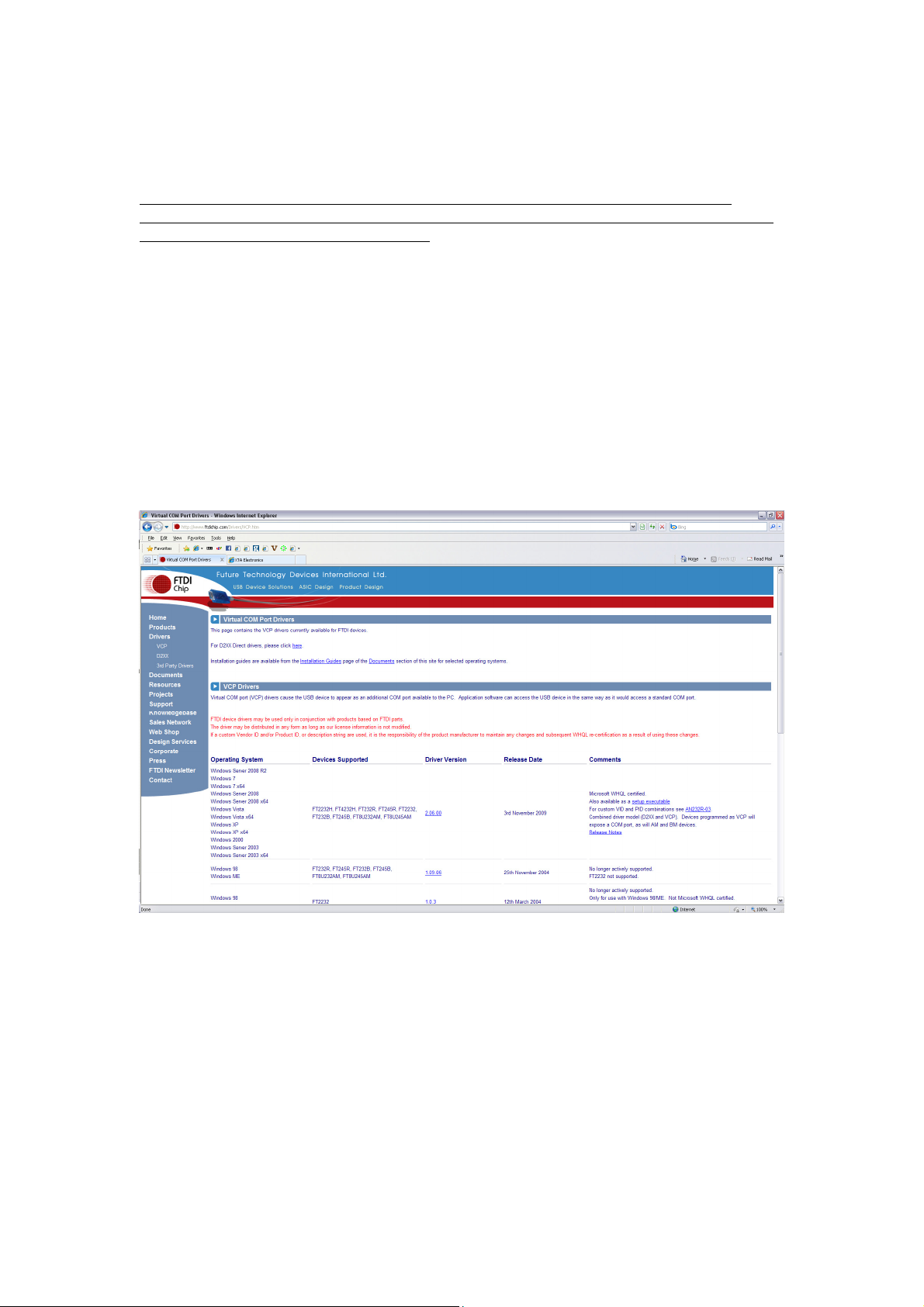
The first time the USB cable is plugged into the PC, Windows will recognize the
connection of new external hardware (a USB-Serial device) and prompt for device
driver to be installed.
This may be obtained from our website, or directly from the Internet at this
address:
http://www.ftdichip.com/Drivers/VCP.htm
Choose the virtual COM port (VCP) driver as appropriate to your operating
system.
Note that, due to the nature of the USB protocol and the “hot swapping” nature of
the system, if the unit is not powered up and plugged into the PC, the COM port
connection will not be available.
Please confirm that the connection is made and the unit is on before continuing.
Page 18
DC1048 Integrated Audio Management
Operator’s Manual
Page 19

Having physically connected the unit, and installed the driver successfully, we
now need to check the virtual COM port that’s being used so we can match this
with the COM port in ICORE.
With the lead plugged in (the COM port won’t show up if the unit isn’t
connected AND powered up!), use the shortcut of the WindowsTM key on your
keyboard + the Pause/Break key to bring up the System properties window:
Press BOTH keys together! Alternatively you can get to the same place through
start
Settings Control Panel System
Press the “Hardware” tab and then “Device
Manager”. This will bring up a window with a list of
all hardware subsections of your computer,
including the COM ports. Expand the section
entitled “Ports” and locate the USB-Serial adapter.
The COM port number it has been assigned is in
brackets after the name.
Make a note of this port number and then start ICORE.
Operator’s Manual
DC1048 Integrated Audio Management
Page 19
Page 20

Expand the window to fill your screen and then, from the menus, choose
Tools Options, and select the Comms tab.
Make sure the COM port number selected from the drop down list matches the
one discovered earlier.
The baud rate must
be set to 115k if
using the direct USB
connection.
The safest method of
connection to avoid
accidentally changing
any device settings is to
select “Retrieve settings
from units” as this will
upload all device(s)
properties and
parameters to the
computer.
Having selected the COM port, this window may now be closed by clicking OK.
We can now scan for connected devices to find the unit. Either select Tools
Autoscan, or press the button on the toolbar. Assuming the ID has been set to 1
as suggested, it should be found almost immediately. You can press “Stop” once
your unit is located.
Page 20
DC1048 Integrated Audio Management
Operator’s Manual
Page 21

Nonetheless, the entire process will take approximately 90 seconds to complete.
As the search continues, the device view should begin to fill up with connected
units. When complete, depending on what’s connected of course, there should
now be a “rack” of devices like this:
Device View Window
Virtual rack shows all connected
units - double click on any device
to open its detailed view in the
main window
System Monitor Window
Every unit is represented here with
metering and comms status
indicator - double click on any device as
for the Device View window to select it
Properties Window
View and edit all non-audio
parameters on the selected
device
Layout of the Main Window
A double click on any device will display its “front panel” for editing of audio
properties. Non-audio properties are shown in the “Properties” pane on the right
hand side of the main window.
Operator’s Manual
DC1048 Integrated Audio Management
Default control
panel for unit,
on-line with
metering
Page 21
Page 22

In the example on the previous page, all devices apart from the first one are offline, as shown by the red indicator on each unit in the Device View and the
System Monitor view. When connected and on-line, the indicators will be green.
A yellow flashing indicator means there is a problem – hover over the device in
question to see a tool tip explaining what is wrong.
Before looking at the details of a device’s controls and properties, here are a few
general pointers about using the software:
The last saved file can automatically be opened when the software is
started by setting the option in the Tools Options General tab.
Settings can be copied between units either using the buttons on the
toolbar (which uses the currently selected amplifier) or by using the rightclick context menu on the units “front panel” or in the Device View for
more detailed options.
The Global Mute has its own toolbar which can be hidden(!).
The error log is stored to a file called “Logfile.txt”, which is stored in the
same directory as the program executable file.
Remember to save your system before closing ICORE to avoid having to rescan
the system every time you open the software. All window positions, zones, and
screen layouts (so positions of the Device View, Properties and System Monitor)
are also saved.
Page 22
DC1048 Integrated Audio Management
Operator’s Manual
Page 23

Reorganising the Main Window
Pick window up by
the title bar and
To move inner windows about, pick them up by their title bar:
begin to drag...
For example, to move the properties window and re-dock it, pick up the
properties window by its title bar and begin to drag it. This will make a number
of docking option anchors appear – these look like this:
Drop the window on one of the anchors to dock it in the new position, as shown
above. Similarly, the system monitor window can be docked either top or bottom
Operator’s Manual
DC1048 Integrated Audio Management
Page 23
Page 24

of the main window, and either fully across this window, or bracketed by the
device view and/or properties window.
The device view and properties windows can be combined into a single tabbed
window by picking either up and dragging it directly onto the other window where
a new anchor will appear.
Drop on left or right of this anchor
to dock properties to the left or right
of the device window.
Drop on the centre of the anchor to
dock as a pair of tabbed panes.
To separate out the windows again, just click on the tab of the window and drag
and drop it as required to select a new position.
Click and drag the tab to
separate the properties out
from the device view again...
Windows can also be left floating by dragging them from their current positions
and just dropping them on the main background.
Page 24
DC1048 Integrated Audio Management
Operator’s Manual
Page 25

Auto-hiding Windows
All inner windows can be set to “auto-hide”, so they disappear into the edge of
the main window when not required to maximise available screen area, but make
them quickly available if necessary.
Remember, if any windows have been closed they can be reinstated through the
menu View Toolbars and Docking Windows.
Operator’s Manual
DC1048 Integrated Audio Management
Page 25
Page 26

Zoning Devices
Main zone (”Main Bar”)
Another zone, “Small Bar”
The zones shown in the Device View and System Monitor windows allow groups of
devices to be logically arranged to reflect their physical locations more accurately
than just one large list of units.
contains 3 units
contains one unit
Things to know about zones:
There's always a master (main) zone, which you can never get rid of.
New zones can be added using the Z+ button at the top of the rack view.
Devices can be moved into new zones just by clicking on them and
dragging them to the required zone. They can also be re-ordered within a
zone in the same way.
Zones can be renamed by double clicking on their names.
Zone can be expanded and collapsed using the in the zone header.
Files will remember the zone layouts including expand/collapse status
when you save them.
Page 26
DC1048 Integrated Audio Management
Operator’s Manual
Page 27

DC1048 “Front Panel” Controls, Readouts and Indicators
10
15
16
17
21
18
11
9
1
2
19
20
3
4
5
6
7
8
12
13
14
1: Unit view mode buttons: switch between matrix mixer (shown here), input
parametric EQ (see page 30) adjustment, and output EQ adjustment including
crossover filters (see page 29).
2: Presets management pane: store, recall, rename and erase complete
snapshot presets, as well as setting up automatic (off-line) timed preset recalls.
Individual snapshots may also be opened and saved as files on the PC. See page
31 for more information on timed presets and preset files.
3: Input linkage controls: link input channels so all adjustments track identically
– note that changing linkage will immediately copy all parameters from the lowest
channel to the others – change with caution!
4: PEQ shortcut buttons: jump directly to the input parametric EQ screen with
the channel(s) selected – same as mode button (1), but also sets the correct
channel.
5: Mute channels: not linked even if channels are. Remember, system mute is
on main toolbar.
6: Input channel fader: this acts on the signal post-ADC and input metering.
The gain may also be changed by clicking above or below the fader knob along
the “track” to adjust the current value in 1dB steps.
7: Input level metering: real time metering shows post-ADC but pre-DSP level.
Operator’s Manual
DC1048 Integrated Audio Management
Page 27
Page 28

8: Input level readout: input gain values may be manually entered by double
clicking on the readout.
9: Unit name: double click to edit the name, which can also be changed through
the Properties View window.
10: Channel names: double click to edit names. These are stored as part of a
preset.
11: Output view mode: switch between output linking set-up, matrix mixer, and
limiters view.
12: Matrix mixer view: mix any combination of input channels to each output –
either enter direct levels numerically by double clicking on the level readout, or
click on the knob and move vertically to adjust mix level in 0.1dB steps. Note
that values below –40dB will mute this matrix feed.
13: PEQ shortcut buttons: jump directly to the input parametric EQ screen with
the channel(s) selected – same as Mode button, but also sets the correct channel.
14: Phase button: Flip the polarity of an output by pressing this (On – Blue
indicator, and 180° out of phase).
15: Delay readout: up to 650mS of delay may be added to any output channel.
Enter direct values numerically by double clicking on the readout, or single click
on the readout and move vertically to adjust time in the current interval (mS,
metres etc.). Step size and units can be changed through the Properties View
window.
16: Output channel metering: real time metering shows level relative to the
limiter threshold with the yellow section illuminating when the limiter threshold
has been reached. Full scale shows 4dB into limiting. Time constants of metering
are also linked to the attack and release times set for the limiter on each channel.
17: Output channel fader: this acts on the signal post-DSP and pre-limiter. The
gain may also be changed by clicking above or below the fader knob along the
“track” to adjust the current value in 1dB steps.
18: Limiters view: auto-limiters on/off – one setting for all 8 channels. When
set to ‘On’ the attack and release times of the limiters are automatically chosen
based on the high pass crossover filter for that channel. More information about
setting accurate limiter thresholds is given in the section on page 48.
19: Limiters view: Program limiter threshold, attack and release: set the
program limiters using these controls. More information about setting up limiters
is given on page 48.
20: Limiters view: Clip limiter threshold and release: set up the clip limiters
with these controls. More info on page 48.
21: Linkage view: Output linkage controls: link output channels so all
adjustments track identically – note that changing linkage will immediately copy
all parameters from the lowest channel to the others – change with caution!
Page 28
DC1048 Integrated Audio Management
Operator’s Manual
Page 29

4
2
3
1
6
5
1: Output channel select: swap between the channel(s) to adjust. Linked
channels will have their buttons illuminated together.
2: Crossover filters: high pass filter: enter frequency numerically by double
clicking on the readout, or single click on the readout and move vertically to
adjust. Response curve will show updates in real time. Note that the node for
the filter will highlight on the curve, and this can also be dragged to adjust the
frequency. Filter type is selected via the drop-down list.
3: Crossover filters: low pass filter: enter frequency numerically by double
clicking on the readout, or single click on the readout and move vertically to
adjust. Response curve will show updates in real time. Note that the node for
the filter will highlight on the curve, and this can also be dragged to adjust the
frequency. Filter type is selected via the drop-down list.
4: Parametric filters: frequency, ‘Q’ and filter gain can all be entered using
methods explained above for the high/low pass filters. Additionally, each band
may be individually bypassed, and the filter type chosen from the drop down list.
More information on some of these individual filters and their usage is given in
the appendix on page 50.
5: Response curve : filter node: adjusting a filter will illuminate its node on the
curve and this allows it to be dragged in real time, updating the tabular
information and adjusting the unit. For parametric filters, holding down the left
mouse button whilst moving the scroll wheel will change the ‘Q’ of the filter.
6: Response curve: shadow EQ: the grey response shown in addition to the
blue overall curve, will change depending on the filter currently being adjusted,
and shows just its contribution to the overall response.
Operator’s Manual
DC1048 Integrated Audio Management
Page 29
Page 30

1
2
Whilst the input EQ and output EQ screens only differ in minor ways – no
crossover filters on the input screen, and one less parametric band – this
screenshot does highlight a couple more points worthy of note for both.
1: Filter number 5 has been set to an elliptical low pass response. This type of
filter has no adjustment for ‘Q’ or gain (being a band pass filter) so these
parameters are removed from the table.
2: Filter number 6 has been selected as a notch filter, and so has a fixed (very
high negative) gain, but still has variable ‘Q’ (which may be increased greatly
above the default value chosen for a much narrower response).
Page 30
DC1048 Integrated Audio Management
Operator’s Manual
Page 31

Timed Presets and Preset Files
2
1
In addition to storing presets within the unit itself, ICORE opens up the
possibility of storing and recalling individual presets from a virtually unlimited
library stored on the PC running the software.
Storage of presets within the unit is accomplished by selecting the required
location from the drop-down list and then choosing Store. Recall is instantaneous
with all settings changing on the unit and updating on the software control
panels. Storing settings will pop up a window allowing the name to be changed
before storing, and renaming allows just the name of a preset to be changed
without saving new settings.
The icon buttons 1 and 2 are used to save and load individual presets from files
stored on the computer, NOT in the unit.
Press button 1 to load a preset. This method effectively bypasses the unit’s
preset storage memory – loading a preset from a PC file will transmit the settings
direct to the unit’s working memory. It will be remembered when the PC is
disconnected or off-line and will be reloaded if the unit is power cycled, but it is
not stored in a user memory within the device itself. To store it in a user
memory, just press the “Store” button after it’s been loaded and choose a
location as normal.
Saving settings into a PC file is accomplished using button 2 – this allows a library
of presets to be set up on the PC and easily copied (or emailed) to other devices.
Remember this doesn’t store the settings in the unit directly – it stores the
current settings shown in the software as a preset file on the PC.
These preset files are independent of the iCore configuration file accessed through
the File > Save option (an “.icd” file). The “.icd” files store all details of all
Operator’s Manual
DC1048 Integrated Audio Management
Page 31
Page 32

connected units and their memories. The “.dcp” files created when storing
3
settings to the PC as described above only hold individual preset settings for a
single preset on a DC1048.
Button 3 (with the clock on it) is used to set up timed preset recalls. Pressing it
will display a window as shown below:
Up to ten timed events can be enabled – these can be either “single shot” events
where the date and time have to be specified, or repeated “weekly” events where
the required days are specified and the time on these days.
Setting The Clock
There is no need to worry about setting the real time clock within the unit itself –
this is automatically updated every time the unit goes on-line using the PC’s clock
settings – make sure this is set correctly or your unit won’t recall things as you
expect! If you don’t want the unit to sync its clock every time, this can be
disabled by changing the “Auto Update RTC” property to “False” in the Properties
view.
Page 32
DC1048 Integrated Audio Management
Operator’s Manual
Page 33

Additional Device Properties
All other properties that are not directly related to audio and real time control are
listed in the Properties window. These are:
General: ID: This is the unit’s address on the network(Read only)
Device Name: Click to edit the name of the unit
Firmware version: Currently running unit firmware (Read only)
Auto Update RTC: Sync the unit’s clock every time it’s on-line
GPI Mode: Select how the unit responds to changes through the
GPI port – the three modes of operation are explained on page 40
Transmit Preset: If enabled, any GPI triggered recalls will also be
echoed onto the RS485 network to trigger other DC1048s.
Memory Offset: Add an offset to the GPI recall location to enable
recalls above 1-4. This is also added to the TX’ed message if
enabled (see previous parameter)
LCD Contrast: Adjust viewing angle of unit’s display
On Delay: Set a countdown time to delay audio fading up when
unit is turned on.
LED Timeout: Set how long LCD and buttons remain at full
brightness after access
Options: Delay Multiplier: Set the step size used when adjusting any delay
times on the unit
Delay Units: Choose how delay times are displayed – in either time
or distance.
Security: Security Code: Last used code for local lock of front panel controls
System Lock: Current local lock state – may be changed remotely,
but see page 37 for details of how this works.
Operator’s Manual
DC1048 Integrated Audio Management
Page 33
Page 34

Connection of Multiple Units on an RS485 Network
Serial No:
BALANCED INPUTS
MANUFACTURED IN
RS Baud: 4800 – 1520 0k
Connect to USB on front
Baud rate must match on all units
DC1048
INPUTS
SYSTEM
CLIP
CLIP
DC1048
COMMS Menu
Connect to RS485 on rear panel
Serial No:
BALANCED OUTPUTS
BALANCED INPUTS
MANUFACTURED IN
11
12
...RS485 out of rear of first unit
INPUTS
SYSTEM
CLIP
CLIP
DC1048
The USB Connection is the easiest and quickest way to connect to a single unit
when uploading presets or updating firmware, and is the best connection for a
“set and forget” system, where the cable can be unplugged and the system then
left secure. If, however, a larger system of more than one unit is required, and
real time monitoring and adjustment of these units is required on a regular basis,
then the RS485 network connection on the rear panel is more useful.
Additionally, other devices can share this RS485 network and can be monitored
and controlled through ICORE.
Connection via front panel USB and break-in to the RS485 Network
Laptop or desktop PC
running
iCORE
software monitors and
controls all units.
Baud rate must be set
to 115k!
COMMS Menu
Mode: Master
ID Number: 1 – 32
tax
Set address for remote access
INPUTS
COMMS
GPI
QUICK ACCESS
SYSTEM
A B C D
INTEGRATED AUDIO MANAGEMENT
CLIP
CLIP
-3
-3
-6
-6
-12
-12
-24
-24
DC1048
OUTPUTS
L+4
LIM
-6
-12
-24
1 2 3 4 5 6 7 8
PRESETS
ICORE
OK
USB from PC into front of
first unit...
into second...
90V-240V AC
WARNING: THIS EQUIPMENT MUST BE EARTHED.
GPIO PORT
50 - 60Hz 30W
DO NOT EXPOSE TO RAIN OR MOISTURE.
1-4: OUTPUT
5-8: INPUTS
9: +5V / 10: CHASSIS GND
RS485
11 - 12: ISOLATED GND
1 2 3 4 56789 10
Mode: Slave
ID Number: 2
RS Baud: 4800 – 1520 0k
tax
COMMS Menu
Mode: Slave
ID Number: 3
RS Baud: 4800 – 1520 0k
tax
COMMS Menu
Mode: Slave
ID Number:
RS Baud: 4800 – 1520 0k
tax
Select next address
INPUTS
COMMS
GPI
QUICK ACCESS
SYSTEM
A B C D
90V-240V AC
50 - 60Hz 30W
9: +5V / 10: CHASSIS GND
RS485
11 - 12: ISOLATED GND
3456789
1 2
Connect to RS485 on rear panel
Select next address
COMMS
GPI
QUICK ACCESS
A B C D
Connect to RS485 on rear panel
4 Select next address
COMMS
GPI
QUICK ACCESS
A B C D
GPIO PORT
1-4: OUTPUT
5-8: INPUTS
11 12
CLIP
CLIP
-3
-3
-6
-6
-12
-12
-24
-24
10
-3
-3
-6
-6
-12
-12
-24
-24
-3
-3
-6
-6
-12
-12
-24
-24
7
6
8
Baud rate must match on all units
INTEGRATED AUDIO MANAGEMENT
WARNING: THIS EQUIPMENT MUST BE EARTHED.
DO NOT EXPOSE TO RAIN OR MOISTURE.
7
6
8
Baud rate must match on all units
INTEGRATED AUDIO MANAGEMENT
Baud rate must match on all units
INTEGRATED AUDIO MANAGEMENT
CAUTION! SHOCK HAZARD.
DO NOT REMOVE COVERS.
BALANCED OUTPUTS
5
CAUTION! SHOCK HAZARD.
DO NOT REMOVE COVERS.
INSTALLATION AUDIO MANAGEMENT
tax
DC1048
1234
OUTPUTS
L+4
LIM
-6
-12
-24
1 2 3 4 5 6 7 8
tax
INSTALLATION AUDIO MANAGEMENT
DC1048
345
12
OUTPUTS
L+4
LIM
-6
-12
-24
1 2 3 4 5 6 7 8
OUTPUTS
L+4
LIM
-6
-12
-24
1 2 3 4 5 6 7 8
THE UK BY
0000001
DC1048
0000001
DC1048
tax
ABCD
PRESETS
ICORE
OK
THE UK BY
tax
ABCD
...continue up to total of
32 units and TOTAL max
cable length of 1000m.
PRESETS
ICORE
OK
PRESETS
ICORE
OK
...Parallel connections from
second unit into third unit...
Page 34
DC1048 Integrated Audio Management
Operator’s Manual
Page 35

Connection directly to the RS485 Network
If a connection to the first unit cannot be easily achieved with a USB cable (due
to location of this unit) then a longer RS485 connection is possible via the rear
panel connection using a suitable RS485 converter. We recommend the KK
Systems USB-485 adapter for simple conversion to RS485.
This device is powered via the USB connection and so has the ability to drive long
cable runs reliably. This device is available from us, or directly from KK Systems
at www.kk-systems.com. The converter comes with a 9-pin D-type fitted as
standard – this has to be adapted to an XLR connection.
To prevent voiding the warranty on the converter, we advise not cutting the 9-pin
off, but rather make up an adapter – the pin out for this is below.
9-pin D type XLR Phoenix
Pin 4 1 1
Pins 3+7
(Brown + Orange)
Pins 8+2
(Black + Yellow)
2 2
3 3
Remember to set the first unit to SLAVE mode instead of MASTER so it
accepts data on the rear Phoenix instead of the USB. Also, the baud rate
setting in iCore now must match that of all connected units.
See page 16 for how to change this.
Operator’s Manual
DC1048 Integrated Audio Management
Page 35
Page 36

Connect to the first unit via its RS485 socket. To connect to further units, just
Serial No:
BALANCED OUTPUTS
MANUFACTURED IN
INPUTS
CLIP
CLIP
DC1048
INPUTS
SYSTEM
CLIP
CLIP
DC1048
COMMS Menu
Connect to RS485 on rear panel
Connect to RS485 on rear panel
Connect to RS485 on rear panel
Serial No:
BALANCED OUTPUTS
MANUFACTURED IN
11
12
...RS485 out of rear of first unit
INPUTS
SYSTEM
CLIP
CLIP
DC1048
Laptop or desktop PC
software monitors and
use standard microphone cable (or similar), come out of the first unit on the
Phoenix and simply parallel the three wires to the next device, and so on down
the chain as shown in the previous diagram.
running
iCORE
controls all units.
COMMS Menu
Mode: Slave
Connect to RS485 on rear panel
ID Number: 1 – 32
RS Baud: 4800 – 15200 k
tax
Set address for remote access
INPUTS
COMMS
GPI
QUICK ACCESS
SYSTEM
A B C D
CLIP
CLIP
-24
-24
Baud rate must match that at PC
INTEGRATED AUDIO MANAGEMENT
-3
-3
-6
-6
-12
-12
DC1048
OUTPUTS
L+4
LIM
-6
-12
-24
1 2 3 4 5 6 7 8
PRESETS
ICORE
OK
USB from PC through
converter and into
rear RS485 connection
on first unit...
into second...
90V-240V AC
WARNING: THIS EQUIPMENT MUST BE EARTHED.
GPIO PORT
50 - 60Hz 30W
DO NOT EXPOSE TO RAIN OR MOISTURE.
1-4: OUTPUT
5-8: INPUTS
9: +5V / 10: CHASSIS GND
RS485
11 - 12: ISOLATED GND
8
1 2 3 456 7 8910
1112
Mode: Slave
ID Number: 2
RS Baud: 4800 – 15200 k
tax
COMMS Menu
Mode: Slave
ID Number: 3
RS Baud: 4800 – 15200 k
tax
COMMS Menu
Mode: Slave
ID Number:
RS Baud: 4800 – 15200 k
tax
Select next address
COMMS
GPI
QUICK ACCESS
SYSTEM
A B C D
90V-240V AC
50 - 60Hz 30W
RS485
1 2
9: +5V / 10: CHASSIS GND
11 - 12: ISOLATED GND
3 4 56789
-3
-3
-6
-6
-12
-12
-24
-24
GPIO PORT
1-4: OUTPUT
5-8: INPUTS
Select next address
COMMS
GPI
QUICK ACCESS
A B C D
-3
-3
-6
-6
-12
-12
-24
-24
4 Select next address
COMMS
GPI
QUICK ACCESS
A B C D
-3
-3
-6
-6
-12
-12
-24
-24
WARNING: THIS EQUIPMENT MUST BE EARTHED.
DO NOT EXPOSE TO RAIN OR MOISTURE.
8
10
INTEGRATED AUDIO MANAGEMENT
INTEGRATED AUDIO MANAGEMENT
INTEGRATED AUDIO MANAGEMENT
CAUTION! SHOCK HAZARD.
DO NOT REMOVE COVERS.
7
6
DC1048
0000001
345
DC1048
12
tax
INSTALLATION AUDIO MANAGEMENT
Baud rate must match that at PC
OUTPUTS
L+4
LIM
-6
-12
-24
1 2 3 4 5 6 7 8
INSTALLATION AUDIO MANAGEMENT
tax
DC1048
0000001
DC1048
CAUTION! SHOCK HAZARD.
DO NOT REMOVE COVERS.
7
6
345
Baud rate must match that at PC
OUTPUTS
L+4
LIM
-6
-12
-24
1 2 3 4 5 6 7 8
Baud rate must match that at PC
OUTPUTS
L+4
LIM
-6
-12
-24
1 2 3 4 5 6 7 8
THE UK BY
BALANCED INPUTS
THE UK BY
BALANCED INPUTS
tax
ABCD
PRESETS
ICORE
OK
tax
ABCD12
...continue up to total of
32 units and TOTAL max
cable length of 1000m.
PRESETS
ICORE
OK
PRESETS
ICORE
OK
...Parallel connections from
second unit into third unit...
We strongly recommend that you use screened cable for these connections and
be sure to ground one end of the screen. As the RS485 drivers used are “quarter
load” devices, the maximum number of nodes that can be connected together is
128, and the maximum theoretical cable length from the first node to the last
node is 1000 metres. This distance will be affected by the cable quality and to
some extent the operating environment.
Page 36
DC1048 Integrated Audio Management
Operator’s Manual
Page 37

Security and Locking
Overview
The DC1048 and ICORE both have security systems that allow for local and
remote security to be implemented entirely independently. Via the front panel of
the unit itself, control may be restricted or entirely prevented. Through ICORE,
access to internal unit settings may be restricted though user levels with
individual rights given to up to ten users, each with their own username and
password.
Local Front Panel Locking
Pressing the
Sys. Lock:
Sys. Lock: Full
Sys. Lock:Sys. Lock:
Menu
Off
Use the and buttons to choose the required level of lock and press OK
The display will show:
with a cursor flashing over the left-most ‘0’. Use the and buttons to set the
digit and press
pressing
[OK]
with PIN: 0000
SYSTEM
Full All front panel functions disabled
FullFull
Menu Only preset recall allowed
MenuMenu
Off All access allowed
OffOff
OK
will display
button will show the lock options, namely
System Menu:…
System Menu:…
System Menu:…System Menu:…
Enter Pin: 0000
Enter Pin: 0000
Enter Pin: 0000Enter Pin: 0000
OK
to move onto the next digit. After setting the last digit,
[OK] –––– Lock Unit
[OK] [OK]
with PIN: 0000
with PIN: 0000with PIN: 0000
Lock Unit
Lock UnitLock Unit
to lock the unit now, press OK, otherwise wait 5 seconds for the menu to drop
out, or press another menu button to escape.
Once locked (depending on if it’s a full or menu lock), pressing any menu key will
display
Menus Locked!
Enter Pin: 0000
Simply enter the PIN again as for locking and press OK to unlock the unit.
Menus Locked!
Menus Locked!Menus Locked!
Enter Pin: 0000
Enter Pin: 0000Enter Pin: 0000
Forgotten the PIN?
Well that’s not very clever, is it? ;) You need to email us for the unlocking
procedure – tech@xta.co.uk.
Operator’s Manual
DC1048 Integrated Audio Management
Page 37
Page 38

Security in
Before accessing the security features in ICORE please read this section carefully
as once enabled, forgotten passwords and usernames cannot be erased and will
To access security features in the software the system needs to be enabled. By
default, all security features are turned off. Enable security by selecting
File > Properties and ticking the box on the “General” tab:
ICORE
require resetting all devices on the network individually!
Next, choose the “User Levels” tab and add a
user, as shown here:
The ‘Admin’ user is the “Top Level” user with access to everything. This user
cannot be deleted. Default name and password is “Admin” and “Password”
respectively. Clicking on the “Admin” user will show that the permissions are all
ticked and this cannot be changed.
To create another user level with fewer permissions, press the “+” button to the
right of the list, and choose the name, password and select the required
permissions. Note that these permissions are system-wide and not related to an
individual unit. They do NOT affect the local locking of the unit(s) connected.
Once another user (or several users) has been added, click OK and then choose
Tools > Switch Users:
Select the username and type in the appropriate
password to switch levels. The current user is
displayed on the bottom left corner of the main
screen.
Next time the system goes on-line, all security settings will be sent to every unit
on the network (users/passwords/permissions). This means that even if another
computer is plugged into the system, the security system will remain in place.
Page 38
DC1048 Integrated Audio Management
Operator’s Manual
Page 39

The rules governing the security system are:
- Security is GLOBAL across the network and not specific to a particular unit.
- Adding a device to the system once security is in place will cause it to
become part of the secure system and it will receive all security info when
the system goes on-line.
- Adding a device from a secure system to an open system (without security)
will trigger a request for the password to be entered as used on the secure
system. Once entered, security may then be disabled and this will be
reflected on the previously secure unit so it won’t request a password next
time the system goes on-line. Failure to enter the correct password for a
device will result in it being ignored when the system is on-line.
- Up to nine user levels can be added.
- Security information is stored in the ICORE file as well as the units, so
usernames and passwords will be compared in case a different secure system
is opened compared to the file open on the computer when going on-line.
Operator’s Manual
DC1048 Integrated Audio Management
Page 39
Page 40

Isolated connection.
Connect external supply to
between common on switches, and
+9volts
The GPI Port
Overview
The GPI port is designed for connection to either isolated or non-isolated systems
to facilitate remote memory recalls without the need of a computer. There are
three modes of operation, as defined in the GPI Menu > GPI
These are explained in the next few pages, but first the difference between
isolated and non-isolated connections.
Pin Number Description
1 – 4 Outputs
Connect to WP-1048 only
5 - 8 Inputs
(0V – off; 2.5V – 10V max = on)
9 Output – +5V
(current limited to 200mA)
GPI via the front panel.
GPIGPI
10 Output – Chassis Ground
(connect for non-isolated use)
11 - 12 Output – Isolated Ground
(connect only for isolated use)
Isolated Connection
Pin 11 is internally connected to the common cathodes of the opto-isolators and
so to trigger them, this must be joined to the negative side of any external
supply. Chassis ground is NOT connected, nor is the available +5v supply on pin
9. Instead, an external power source provides a voltage, which is switched as
necessary onto the anodes of the opto-isolators triggering memory recalls.
Momentary Action
Switch (Mem #01)
Page 40
pin 11 ground only.
DC1048 Integrated Audio Management
Operator’s Manual
Page 41

Non-Isolated Connection
Non-isloated connection.
Connect pin 10 to pin 11 to
Momentary Action
Switch (Mem #01)
If galvanic isolation is not required, then the GPI port can be used to provide its
own supply for the opto-isolators. In this mode, the common cathodes connected
on pin 11 must be connected to the chassis ground on pin 10. The +5V supply on
pin 9 is then used to trigger memory recalls by switching it to pins 5-8 as
required.
join grounds.
Simple Mode
The diagram above shows four switches connected individually to the four input
lines on the GPI. Simple Mode allows for the recall of four contiguous memories
triggered by pressing one of the four switches. These can be momentary as
shown, or may be latching if some form of feedback is required locally. By
default, the memories recalled will be numbers 01-04, but this can be changed by
adding an offset through GPI > Mem. Offset
number, so an offset of 2 will recall locations 03 – 06 and so on.
Mem. Offset which will move the starting
Mem. Offset Mem. Offset
Operator’s Manual
DC1048 Integrated Audio Management
Page 41
Page 42

Complex Mode
The difference between simple and complex mode is simply how the input lines
are interpreted by the unit when triggered. Simple mode will only read a single
line at a time (triggering multiple lines will result in the lowest numbered one
being used). Complex mode reads the four lines as a binary number and so
allows for recall of up to 16 memories, without recourse to the memory offset
feature.
GPI INPUT LINES
8 7 6 5 RECALLED
0 0 0 1 #01
0 0 1 0 #02
0 0 1 1 #03
0 1 0 0 #04
1 1 0 1 #14
1 1 1 0 #15
1 1 1 1 #16
MEMORY
Panel Mode
Panel mode is reserved for connection to a WP-1048 touch wall panel. Please
refer to the installation instructions and operating manual for this product.
If the unit’s GPIO terminals are not terminated with screened cables fast rising
transients from extreme RF fields, or ESD strikes over 4000 volts may cause
disturbance to the status LEDs on the unit. This will not affect audio performance
and will be corrected on the next power up cycle.
Page 42
DC1048 Integrated Audio Management
Operator’s Manual
Page 43

Appendix I: Updating Device Firmware
Overview
The firmware that runs the DC1048 hardware and controls the remote comms
may be updated using the loader engine built into ICORE. Before explaining
how to update the firmware, please note that
ONLY ONE DEVICE MAY BE UPDATED AT A TIME – TURN OFF ALL OTHER
CONNECTED UNITS DURING THE UPDATE PROCEDURE!
The other devices on the network don’t need to be physically disconnected, just
turned off (NOT STANDBY – OFF!) so that ICORE can determine which model it
has to update and confirm the update has been a success.
Note that DC1048 units cannot be updated over the audio transport
bridge (i.e. via a Ti-Breakout box) and must be directly connected to the
local USB on the front panel and the unit set to Master mode in the
COMMS menu.
Update Procedure Using
Before starting any updates…
SWITCH OFF ALL UNITS ON THE NETWORK (PROCESSORS, AMPS AND
BREAKOUTS) APART FROM THE ONE TO BE UPDATED!
CLOSE ALL OTHER OPEN PROGRAMS ON YOUR COMPUTER!
Now, in ICORE, select Tools Preset/Firmware Loader. You must be OFF-LINE
for this choice to be available. Make sure you have changed the Comms mode on
the unit to Master
Master so it enables the USB connection.
Master Master
ICORE
Operator’s Manual
DC1048 Integrated Audio Management
Page 43
Page 44

The loader will start scanning for all connected devices to determine what unit it
has to update. After a few seconds the device will be found and identified (its
Power LED will begin to flash). Check the model number, which will be shown in
the status pane and if OK, press the “Load” button.
The unit will mute and the update will start.
DO NOT START ANY OTHER PROGRAMS DURING THE UPDATE!
DO NOT DISCONNECT THE BREAKOUT DURING THIS PROCEDURE!
During the update the LCD will show a counter detailing the progress. The
process takes less than 90 seconds and when complete, the unit will reboot
automatically and a message will confirm that the update is complete.
Don’t forget to set the
Comms mode back to
Slave
Slave if the unit was
SlaveSlave
part of a network.
Repeat this procedure
for all units as required.
Page 44
DC1048 Integrated Audio Management
Operator’s Manual
Page 45

Appendix II: Limiter Types and Setting Thresholds
Program Limiter and “D-Max” Limiter
The DC1048 has two levels of dynamic protection on its outputs – a traditional
program limiter, and a newly introduced “D-Max” limiter.
Program Limiter
High performance digital limiters are provided for each output with control over
attack time, release time and threshold parameters - see page 48 for details. This
level of control allows the user to balance the required subjective quality of the
limiter against the driver protection requirements. It does also mean that an
incorrectly set limiter may sound awful! In particular, as with all limiters, using
too fast an attack or release time will result in excessive low frequency distortion.
On the limiters screen in ICORE there is an option for automatic limiter time
constants. Use this option if you are unsure how to set the time constants
manually. XTA recommend the use of the automatic setting.
In this mode the time constants will be automatically set from the High-Pass filter
frequency according to the table below.
The time constants are set by the high pass filter frequency for that channel.
High Pass Filter Auto Attack Time Release Time
<10Hz – 31Hz 45mS x16 (720mS)
31Hz – 63Hz 16mS x16 (256mS)
63Hz – 125Hz 8mS x16 (128mS)
125Hz – 250Hz 4mS x16 (64mS)
250Hz – 500Hz 2mS x16 (32mS)
500Hz - 1kHz 1mS x16 (16mS)
1kHz – 2kHz 0.5mS x16 (8mS)
2kHz – 32kHz 0.3mS x16 (4mS)
Operator’s Manual
DC1048 Integrated Audio Management
Page 45
Page 46

“D-Max” Clip Limiter
The main limitation with traditional dynamics control is the inability of the
processing to react truly instantaneously to the signal. One of the most
significant advantages of digital signal processing over analogue is the ability to
delay the audio signal precisely and without extensive complex hardware. The
entire domain of digital signal processing is based around the combination of
delaying, multiplying, and accumulating numbers (representing samples of audio)
to implement all the filters and dynamics processing we have come to expect
today.
In the case of dynamics processing, being able to delay a signal allows the
processor module to delay the main signal in relation to the sidechain (the signal
being monitored relative to the threshold), so that it can compensate for peaks
prior to the arrival of the main signal.
Consider the situation of a monitor engineer listening to a band perform. Having
no access to dynamics processors, he has had to resort to manually ‘riding the
faders’ in an attempt to keep control of the levels. Should the level of one of the
channels on his desk reach an unacceptably high level, he will turn it down
appropriately.
There is a hidden
sidechain in operation
even in this case. The
main signal path is fed
through the monitor
desk and the gain
controlled by adjusting
the fader.
The sidechain is formed
by the feedback path
between the engineer’s
ears checking the level
and his brain instructing
his hand to turn the fader down if the volume goes over the threshold he has
chosen.
In this case, the delay between the signal actually going over the threshold, the
engineer registering the situation, and then turning the signal down will be in the
order of several hundred milliseconds at best. This will only be true if he is not
distracted – in reality, it may be several seconds before any gain reduction is
imposed on the signal to bring it under control.
Page 46
DC1048 Integrated Audio Management
Operator’s Manual
Page 47

For an analogue dynamics processor,
the situation is much better.
Controlling the gain electronically, and
not relying on a human sidechain
feedback mechanism, it can react
much more quickly.
The red waveform represents the
input to the dynamics module, with
the dotted line showing the threshold
for gain control to occur. There are
several peaks towards the start of this
signal that are above the threshold,
and so the dynamics processing
should react to these as appropriate.
(In this case reduce the gain).
The blue waveform shows the output of the dynamics module. The circled peak
demonstrates that the processor has missed the first peak above the threshold
(as it is very fast and short), but has ‘caught up’ shortly afterwards, keeping all
other peaks under control. As it is unable to predict what is coming, this will
always be a failing with analogue dynamics processing.
The “D-Max” clip limiter predelays the sidechain signal, resulting in a “zero
overshoot” limiter, which is able to catch all peaks and provide a reliable absolute
maximum setting for the output of any channel.
The predelayed sidechain is shown
in green, with the main signal in
red. As the main signal arrives
slightly after the sidechain, the
output from the unit does not suffer
from the overshoot problem.
Remember that this delay is only in
the order of tens of uS,and is a
predelay – the sidechain is moved
back in time in relation to the main
signal. Inserting a delay into the
main signal path of an analogue
dynamics processor will achieve
similar results, but with the penalty
of delaying the main signal by the
amount of look ahead delay
introduced.
The “D-Max” limiter has only two
parameters to adjust - the release time (either Fast, Medium, or Slow) and the
threshold. Note that the threshold is set to be a minimum of 2dB above the
threshold of the program limiter – setting the threshold to 10dB Above, means
that no more than 10dB of overshoot above the threshold of the program limiter
will ever be allowed. The release time may also be set to follow the High Pass
filter of the output by selecting the “Auto” option on the limiters screen in
ICORE.
Operator’s Manual
DC1048 Integrated Audio Management
Page 47
Page 48

Setting Accurate Limiter Thresholds
The limiters in the DC1048 are intended to be used for loudspeaker driver
protection, as opposed to amplifier protection. All modern professional power
amplifiers designed for live sound use have their own limiters, which are tailored
to protecting the amplifier from clipping. The following section describes how to
set up the units’ limiters to provide exceptional protection against driver
overheating, and cone over-excursion.
Most speaker systems are given a power rating in Watts RMS. This is the
maximum continuous power that the system will handle and often appears very
conservative. In reality, as music program is far from continuous in nature, the
peak power of the system is much higher – up to ten times the continuous figure.
Any limiter, which is to protect the driver from damage, must be able to fulfil the
following tasks.
Have an attack time, which is calculated to allow transients through but
keep the RMS level below the speaker manufacturers specification;
Have a release time, which is sufficiently long to avoid the limiter itself
modulating the program;
Be intelligent enough to adjust the envelope of the limiter according to the
frequency content of the program material.
Page 48
DC1048 Integrated Audio Management
Operator’s Manual
Page 49

The program limiters are capable of performing all these tasks. The only
parameter that the user must set manually is the threshold, and it is crucial that
this is done correctly. Consider the table below.
dB Ratio Vrms
45 177.83 137.74 2371.71 4743.42 9486.83
44 158.49 122.77 1883.91 3767.83 7535.66
43 141.25 109.41 1496.45 2992.89 5985.79
42 125.89 97.52 1188.67 2377.34 4754.68
41 112.20 86.91 944.19 1888.39 3776.78
40 100.00 77.46 750.00 1500.00 3000.00
39 89.13 69.04 595.75 1191.49 2382.98
38 79.43 61.53 473.22 946.44 1892.87
37 70.79 54.84 375.89 751.78 1503.56
36 63.10 48.87 298.58 597.16 1194.32
35 56.23 43.56 237.17 474.34 948.68
34 50.12 38.82 188.39 376.78 753.57
33 44.67 34.60 149.64 299.29 598.58
32 39.81 30.84 118.87 237.73 475.47
31 35.48 27.48 94.42 188.84 377.68
30 31.62 24.49 75.00 150.00 300.00
Pwr 8 Ω Pwr 4 Ω Pwr 2 Ω
Using this table it is a straightforward procedure to work out the required setting
of the limiter thresholds for the system.
First, check the RMS power rating of the speaker system and its impedance.
Look up this value in the table above, using the closest value below the rated
power of the speaker system. Note the corresponding ‘dB’ value.
Check the gain of your amplifier, which needs to be in ‘dB’.
Subtract this gain figure FROM that obtained from the table to find the required
absolute setting for the limiter thresholds.
Note that, for safety, always set the limiter threshold 1 or 2 dB below the
maximum allowable worked out using the above method.
ALWAYS REFER TO YOUR SPEAKER MANUFACTURER FOR LIMITER SETTINGS.
Operator’s Manual
DC1048 Integrated Audio Management
Page 49
Page 50

Appendix III: Parametric Filter Types and Their Uses
A wide selection of filter types has been made available under the PEQ sectiosn
when editing input or output filters. Each filter type will be explained in turn in
the following section.
Standard Parametric EQ
The standard parametric band has adjustable frequency, ‘Q’ (or Bandwidth) and
Gain controls. These affect a range of frequencies symmetrically about the centre
frequency as shown in the
graph.
Various levels of cut/boost are
shown to the left, along with
various ‘Q’ settings (gain
boosts only are shown below).
Remember that ‘Q’ is
1/Bandwidth, so the higher
the ‘Q’, the lower the
Bandwidth, and the smaller
the range of frequencies
affected.
Page 50
DC1048 Integrated Audio Management
Operator’s Manual
Page 51

Shelving EQ (High Shelf shown)
Remember that ‘Q’ is 1/Bandwidth, so the
higher the ‘Q’, the lower the Bandwidth,
and the smaller the range of frequencies
affected.
The shelving EQ has adjustable
frequency, ‘Q’ (or Bandwidth) and
Gain controls. These affect a
range of frequencies from the
turnover freqency as shown in the
graph. For a high shelf,
frequencies above the turnover
frequency will be affected. For a
low shelf, frequencies below the
turnover frequency will be
affected.
Various levels of cut and boost
are shown to the left, along with
various ‘Q’ settings (gain boosts
only are show below).
Note that ‘Q’ settings above 0.75 will
result in slight overshoot in the filter
response (as seen at the highest setting
to the right). This is normal behaviour
and does not indicate instability.
Creating a Flat-topped EQ Response
Use two EQ bands, BOTH
configured as low shelves. For an
overall BOOST, set the Lower
frequency filter to BOOST the
desired amount, and the Upper
frequency filter to CUT by the
same amount.
This example shows one filter at
100Hz and the other at 2kHz,
with the 100Hz filter at –10dB,
and the 2kHz filter at +10dB.
Varying the ‘Q’ affects the slope –
values above 0.75 cause
overshoot as shown. Assymetrical responses may be achieved by adjusting the
‘Q’ of each filter independantly.
Operator’s Manual
DC1048 Integrated Audio Management
Page 51
Page 52

Bandpass Filter
Note that the response is fundamentally NOT a flat-topped response (so it is not
constructed from a high pass and low pass). See previous page for details of how
to construct a flat-topped filter response.
The bandpass filter has adjustable
frequency and‘Q’ (or Bandwidth)
controls. These affect a range of
frequencies symmetrically about
the centre frequency as shown in
the graph, gradually cutting the
level, but providing no gain.
Remember that ‘Q’ is
1/Bandwidth, so the higher the
‘Q’, the lower the Bandwidth, and
the smaller the range of
frequencies affected.
Notch Filter
The notch filter has adjustable
frequency and ‘Q’ (or Bandwidth)
controls. These affect a range of
frequencies symmetrically about
the centre freqency as shown in
the graph.
Remember that ‘Q’ is
1/Bandwidth, so the higher the
‘Q’, the lower the Bandwidth, and
the smaller the range of
frequencies affected. The notch
filter depth varies with bandwidth
– the wider the filter, the lower
the depth will be.
Page 52
DC1048 Integrated Audio Management
Operator’s Manual
Page 53

All Pass Filter
Phase Filter
The allpass filter has adjustable
frequency and ‘Q’ (or Bandwidth)
controls. These affect the
frequency at which the phase
effectively flips 180°, and the
‘speed’ at which this transition
occurs.
The graph shows an allpass filter
centred at 1kHz, with various ‘Q’
settings – the higher the ‘Q’ the
faster the transition.
The phase filter has adjustable
frequency, and phase shift
controls. This introduces a phase
shift that gradually changes from
180° above the centre frequency
to the specificed value at the
centre frequency, and tending
towards 0° below the centre
frequency.
This graph shows the phase shift relative to the input (ignoring processing
delays), in 10° steps – the filter will actually provide higher resolution than this,
operating in 2° steps.The filter is centred at 1kHz in this example.
Operator’s Manual
DC1048 Integrated Audio Management
Page 53
Page 54

Low/High Pass Variable ‘Q’ Filter (Low Pass shown)
The low and high pass variable ‘Q’
filters have adjustable frequency
and ‘Q’ (or Bandwidth) controls.
The ‘Q’ control adjust the
damping of the filter, so that low
‘Q’ settings show less overshoot
at the turnover frequency, but
also slower roll-off.
Remember that ‘Q’ is
1/Bandwidth, so the higher the
‘Q’, the lower the Bandwidth, and
the smaller the range of
frequencies affected. The filter is
primarily 12dB/Octave, but in
achieving this sort of roll-off with a high ‘Q’ value will result in quite a large
overshoot in level at the turnover frequency. This type of filter is often also called
a resonant filter.
Page 54
DC1048 Integrated Audio Management
Operator’s Manual
Page 55

Elliptical filters
1
2
3
The elliptical filter has adjustable
frequency only. This sets the 3dB
point of the filter which features a
steep roll-off of approximately
36dB/Octave down to one Octave
above (or below in the case of a
HPF) the turnover frequency.
However, the gain does increase
again above this frequency to
settle at 12dB down from 0dBr.
This filter can be used in
conjunction with the standard
crossover filters to produce
sharper roll-offs than would be
otherwise achievable. The use of this filter is explained in the following example.
The graph shows three different
low pass filter shapes.
Number 1 is a standard
24dB/Octave Linkwitz-Riley
curve.
Number 2 is a 48dB/Octave
Linkwitz-Riley.
As can be seen, number 2 is
significantly steeper in roll-off
than number 1, as would be
expected.
However, number 3 is a 12dB/Octave Butterworth filter with an Elliptical Low Pass
filter following it. This produces a combined roll-off very close to that of the
48dB/Octave (with the side effect of the response rising again after the initial
drop from the pass band).To produce a crossover filter of this shape it is simply a
case of setting the low (or high) pass filter for that output to the desired
crossover frequency, and selecting a 12dB Butterworth response:
Then select a parametric section on the same output, and modify its behaviour to
select an HPF Elliptical filter. Set the turnover frequency of this filter to be the
same as that of the crossover filter. Make sure you choose a high pass elliptical
to work with a high pass crossover, and low pass elliptical to work with a low pass
crossover.
Operator’s Manual
DC1048 Integrated Audio Management
Page 55
Page 56

Appendix IV: Maintenance
The unit will require little in the way of routine maintenance, apart from
occasional routine checking of the fan outlets on the side panel.
Cleaning the casework should only be done with a cloth lightly dampened with
water only. The use of chemical cleaners may damage the paint finish or dissolve
printing!
Do not use abrasive cleaners, as the plastic insert will scratch - marks on this
section can normally be polished out with a small amount of rubbing metal polish
applied with a cloth, and then buffed to a shine again.
Page 56
DC1048 Integrated Audio Management
Operator’s Manual
Page 57

Appendix V: Specifications
Inputs: 4 electronically balanced
Impedance: > 10k ohms.
CMRR : >65dB 50Hz - 10kHz.
Outputs: 8 electronically balanced
Source Imp: < 60ohms
Min. Load: 600ohm
Max. Level: +20dBm into 600 ohm
Frequency Resp.:+½dB 20Hz-20kHz
-3dB @ 32kHz
Dyn. Range:>112dB 20Hz-20k unwtd
Distortion:< .02%@1kHz,+18dBm
Maximum Delay: 650 mS
Min Step Size: 0.3 µS
Input Gain: +6dB to -40dB in 0.1dB
steps
Output Gain: +15dB to -40dB in 0.1dB
steps and mute
Parametric Equalisation
Limiters
Program Limiter:
Threshold: +22dBu to -10dBu
Attack time: 0.3 to 90 milliseconds
Release time: 2/4/8/16/32 x Attack
time
“D-Max” Limiter:
Attack Time: -60uS
Release Time: Slow/Medium/Fast
Display: 2 x 16 Character LCD
Input meter: 2 x 5 point, -24dB to
digital clip.
Output meter: 8 x 6 point, -24dB to
+4dB into limit.
Connectors
Inputs: 3 pin Phoenix
Outputs: 3 pin Phoenix.
Comms – USB (Front Panel)
RS485:3 pin Phoenix
8 per Input / 9 Sections per Output
Filter Gain: +15dB to -30dB in 0.1dB
steps.
Freq. Range: 19.7Hz - 32kHz, 1/36
octave steps.
Filter Q / BW: 0.4 to 128 / 2.5 to 0.008
(Sections switched to shelving
response)
Low frequency: 19.2Hz - 1kHz
High frequency: 1kHz - 32kHz
Shelf gains: ±15dB in 0.1dB steps.
High and Lowpass Filters
Filters: 1 of each per output.
Freq. Range HPF: 10Hz - 16kHz
1/36 octave steps.
Freq. Range LPF: 35Hz - 22kHz
1/36 octave steps.
Responses:
1st Order 6dB/Oct.
Bessel/Butterworth/Linkwitz-Riley 1224dB/Oct.
Bessel/Butterworth 18dB/Oct.
Power: 3 pin IEC
Power: 60 to 250V ±15% @ 50/60Hz.
Consumption: < 30 watts.
Weight: 3.3kg. Net (4.7kg. Shipping)
Size: 1.75"(1U) x 19" x 11.8"
(44 x 482 x 300mm) excluding
connectors
Latency: 1.5mS (analogue in –
analogue out @ 96kHz)
Due to continuing product improvement
the above specifications are subject to
change.
Operator’s Manual
DC1048 Integrated Audio Management
Page 57
Page 58

Page 58
DC1048 Integrated Audio Management
Operator’s Manual
Page 59

Index
A
Admin ........................................ 36
All Pass ...................................... 51
Automatic preset recalls ............... 29
B
Bandpass ................................... 50
Baud Rate .................................. 14
C
Change users .............................. 36
Clip Limiter ................................. 44
Clock/calendar ............................ 30
Closed contact recalls .................. 39
Comms Menu .............................. 14
D
Delay
Look Ahead ........................ 44
Delay Units ................................. 31
Direct Connection to RS485 Network
............................................. 33
D-Max ....................................... 44
E
G
GPI Menu .................................. 14
GPI Port
DIfference between Simple &
Complex ......................... 39
Isolated Connection ............ 38
Non-isolated Connection ...... 39
Pinout ............................... 38
I
iCore
Adjusting crossovers ........... 27
Adjusting PEQ filters ........... 27
Auto-hiding Windows .......... 23
DC1048 Properties .............. 31
DC1048 Software Panel See ore
Main Window ..................... 19
Moving Windows ................ 21
Scan for units .................... 18
Security ............................ 36
Set COM port ..................... 18
Zoning Devices .................. 24
ID Number ................................ 14
Installation
Electrical ............................. 9
Mechanical........................... 9
Elliptical Filter ............................. 53
F
Firmware Update
Using iCore ........................ 41
Flat Topped EQ ........................... 49
Forgotten PIN ............................. 35
Front Panel
Comms Menu Button ........... 11
GPI Menu Button ................ 11
Input Meters ...................... 11
LCD Display ....................... 11
Output Meters .................... 12
Preset Buttons ................... 12
System Menu Button ........... 11
USB Socket ........................ 12
Operator’s Manual
DC1048 Integrated Audio Management
L
Limiter Threshold ....................... 46
Limiters
Auto Time Constants ........... 43
Program and Clip ................ 43
Setting thresholds .............. 46
Look Ahead ................................ 44
Look Ahead Delay ....................... 44
M
Mains Wiring Colours..................... 6
Maintenance .............................. 54
Master Mode .............................. 14
Page 59
Page 60

N
Network multiple units ................. 32
Notch ........................................ 50
NTH Response ............................ 53
P
Phase ........................................ 51
PIN Number ................................ 35
Polarity ...................................... 51
Disable remote control ........ 35
Hardware front panel .......... 35
Stop memory recalls ........... 35
Setting the clock ........................ 30
Setting the date ......................... 30
Shelving EQ ............................... 49
Sidechain
Delay ................................ 44
Slave Mode ............................... 14
Standard Parametric ................... 48
Switch users .............................. 36
System Menu ............................. 14
R
Rear Panel
Audio Inputs ...................... 13
Audio Outputs .................... 13
GPI Port ............................ 13
RS485 ............................... 13
Remote Control
USB Connection ................. 15
Remote memory recalls ............... 39
Remote Recalls ........................... 31
Resonant Filter............................ 52
RS485
Connections ....................... 33
Maximum distance .............. 34
Maximum drops ................. 34
RS485 Connection ....................... 32
S
Safety Information ....................... 6
Security
T
Thresholds for limiters ................. 46
Timed presets ............................ 29
U
Unpacking .....................................
Update Firmware ........................ 41
USB Bridge to RS485 .................. 32
USB Drivers ............................... 16
USB-485 wiring .......................... 33
User Permissions ........................ 36
V
Vari-Q ....................................... 52
Virtual COM Port ......................... 17
W
Wake Up Time ............................ 31
Page 60
DC1048 Integrated Audio Management
Operator’s Manual
 Loading...