


Page 2 5 Series
5 Series Operator’s Manual
5 Series 5 Series
5 Series
5 Series Quick Reference
5 Series5 Series
Editing channels : press channel’s GAIN key. First press accesses
that channel’s gain. To scroll through channel’s parameters, use the
BACK and NEXT keys. Second press accesses last viewed parameter.
Third press will drop back to the default screen.
Accessing menus: press the MENU key. Use the BACK and NEXT
keys to select the sub-menu required, and enter the sub-menu using the
ENTER key. This applies to all levels of menu. ENTER always
confirms selections.
The Menus and their Contents
GLOBAL MEMORY
GLOBAL MEMORY Sub-menu: Recall/Store/Erase input, graphic
GLOBAL MEMORY GLOBAL MEMORY
EQ, dynamic EQ, and crossover settings, or combinations of these.
INPUT SECTION
INPUT SECTION Sub-menu: Set up input ganging, and GEQ ‘Q’
INPUT SECTIONINPUT SECTION
setting.
CROSSOVER
CROSSOVER Sub-menu: Set up or adjust crossover design, including
CROSSOVERCROSSOVER
routing and auto limiter setting. Also set up output ganging.
INTERFACE
INTERFACE Sub-menu: Comms interface setup (RS232 and RS485),
INTERFACEINTERFACE
G.P.I. interface configuration, and wireless interface.
SYSTEM
SYSTEM Sub-menu: Used to view unit’s status, and select various
SYSTEMSYSTEM
global options such as PEQ ‘Q’ or bandwidth units, delay units, and
output metering point (pre/post mute).
SECURITY
SECURITY Sub-menu: Used for locking various operations of the
SECURITYSECURITY
unit, using a 4 digit code.
AES/EBU
AES/EBU Sub-menu: Switch outputs from analogue to digital and
AES/EBUAES/EBU
monitor AES input status info. (AES inputs are switched via rear panel.)
DYNAMIC
DYNAMIC Sub-menu: Change how gain reduction meters behave.
DYNAMICDYNAMIC
Notes
The output meters show level, in dB from the limiter threshold, and the
input meters show level from clipping the A-D converters,
pre-gain and all EQ.
When editing DEQ or compressors, meters read downwards and show
gain reduction for each DEQ section or compressor respectively.
The high and low pass crossover filters are defined independently on
each output channel.
To access the limiter attack and release parameters, select “AutoLimiter
TimeCst: No” when designing a crossover.
To swap parametric filter units between bandwidth (‘BandW’) and ‘Q’,
enter System
System Sub-menu, select ‘Filter Q / Bandwidth’, and select
SystemSystem
required readout units.
To swap delay time units, enter System
Time / Distance’, and select required readout units.
Pressing an EDIT key flashes corresponding channels routed to / from
that channel.
5 Series Operator’s Manual Page 3
5 Series 5 Series
System Sub-menu, select ‘Delay
SystemSystem

Contents
Declaration Of Conformity 6
Important Safety Instructions 7
Instructions De Securite Importantes 8
Thanks 9
Unpacking the unit 9
Introduction 10
Features 10
Front Panel Familiarisation 11
Rear Panel Connections 12
Operating the 5 Series
Note about operation with AudioCore software. 13
Start-up procedure 13
Preliminary Set-up as a Crossover (DP548 & DP544) 13
Preliminary Set-up as Insert Channel Processing (DP544) 13
Input Channel Makeup 14
Output Channel Makeup 14
Preset Routing Configurations: DP548 14
Preset Routing Configurations: DP544 17
Free Assign Routing 18
Full Matrix Mixing 18
Editing Audio Parameters – Input Channels 19
Input Gain 19
Base Delay 19
Input Graphic EQ 19
Input Parametric EQ 19
Editing Audio Parameters – Output Channels 21
Output Gain 21
Output Polarity 21
Output Delay 21
Output High Pass Filter 22
Output Low Pass Filter 22
Output Parametric EQ 22
Output Compressor 23
Output Limiter 24
Output “D-Max” (Clip) Limiter 24
Input Ganging and Output Ganging 25
Menus in Detail 27
Memory Structure 29
Remote Control Interface Operation 31
RS232 Interface 31
RS232 Connection (Single Unit) 31
Loading New Software via a PC 32
RS232 Connection (Multiple Units) 32
Shadow ID Numbers 33
RS485 Connection 34
5 Series 13
5 Series5 Series
Page 4 5 Series
5 Series Operator’s Manual
5 Series 5 Series

AES Inputs and Outputs 36
AES Input 36
AES Output 36
AES Diagnostics and Status Information 37
Security and Locking 38
Entering the Password to Complete the Locking Operation 38
Unlocking the Unit 39
Forgotten the Password? 39
PCMCIA Card and Compact Flash Card Usage 40
Preset Library Updates via the card 40
Unit Software Updates via the card 40
Unit Cloning 41
Copying Unit Software and Preset Files 41
Copying Data from Source Unit 41
Loading Data into Destination Unit 41
Cold Start Reboot Procedure 41
Advanced Audio Features 42
Graphic Equaliser Behaviour 42
The “GQ600” behaviour 42
The “Special” behaviour 43
What is Dynamic EQ? 44
Quadrant/Mode I: “Boost Above” 44
Uses of “Boost Above” mode. 44
Uses of “Cut Above” mode. 45
Uses of “Cut Below” mode. 46
Uses of “Boost Below” mode. 47
Dynamic EQ operating modes 48
Parallel Mode 48
Sequential Mode 48
DEQ Filter Types and Use of Full Bandwidth Mode 49
Setting the Attack and Release times 50
The Compressor ‘Knee’ Control 51
Program Limiter and “D-Max” Limiter 52
Program Limiter 52
“D-Max” Clip Limiter 53
Setting Accurate Limiter Thresholds 55
Crossover Filter Slopes 56
Time Alignment 56
Parametric Filter Types and Their Uses 57
Standard Parametric EQ 57
Shelving EQ (High Shelf shown) 58
Creating a Flat-topped EQ Response 58
Notch Filter 59
All Pass Filter 60
Phase Filter 60
Low/High Pass Variable ‘Q’ Filter (Low Pass shown) 61
Elliptical filters 62
Specifications 63
Warranty 64
Options and Accessories 64
Index 65
Operator’s Manual Page 5

Declaration Of Conformity
ta
x
We, the manufacturer:
XTA Electronics Ltd.,
The Design House,
Vale Business Park,
Worcester Road,
Stourport on Severn,
Worcestershire,
England
DY13 9BZ
acknowledge our responsibility that the following products:
Kind of equipment: Audio processor
Commodity Code: 8518408990
Type Designation: DP548, DP544
are manufactured:
in accordance with EMC Directive 2004/108/EC,
in compliance with the following norm(s) or document(s):
Technical Regulations: EN55103-1:1996, EN55103-2:1996
and
in accordance with the Low Voltage Directive 2006/95/EC,
in compliance with the following norm(s) or document(s):
Technical Regulations: EN/IEC60065:2002 7th Edition
Signed: …………………………………………………………………
Name: Alex Cooper
Position: Research and Development Manager
Date: January 2012
Page 6 5 Series
5 Series Operator’s Manual
5 Series 5 Series

Important Safety Instructions
CAUTION: RISK OF ELECTRIC SHOCK.
DO NOT OPEN
The lightning flash with arrowhead
symbol within an equilateral triangle
is intended to alert the user to the
presence if uninsulated “dangerous
voltage” within the product’s
enclosure that may be of sufficient
magnitude to constitute a risk of
electric shock to per
sons.
WARNING: Apparatus with CLASS I construction shall be connected to a MAINS socket outlet with a protective earthing
connection.
WARNING: To prevent injury, this apparatus must be securely attached to the rack in accordance with the installation
instructions.
1. Read these instructions.
2. Keep these instructions.
3. Heed all warnings.
4. Follow all instructions.
5. Do not use this apparatus near water.
6. Clean only with a dry cloth.
7. Do not block any ventilation openings,
install in accordance with the manufacturer’s
instructions.
8. Do not install near any heat sources, such
as radiators, heat registers, stoves or other
apparatus (including amplifiers) that produce
heat.
9. Do not defeat the safety purpose of the
polarized or grounding-type plug. A polarized
plug has two blades with one wider than the
other. A grounding-type plug has two blades
and a third grounding prong. The wide blade or
the third prong are provided for your safety. If
the provided plug does not fi t into your outlet,
consult an electrician for replacement of the
obsolete outlet.
10. Protect the power cord from being walked
on or pinched particularly at plugs,
convenience receptacles and the point where
they exit from the apparatus.
11. Only use attachments/accessories
specified by the manufacturer.
12. Use only with the cart, tripod, bracket or
table specified by the manufacturer, or sold with
the apparatus. When a cart is used, use caution
when moving the cart/apparatus combination to
avoid injury from a tip over.
13. Unplug this apparatus during lightning
storms or when unused for a long period of time.
14. Refer all servicing to qualified service
personnel. Servicing is required when the
apparatus has been damaged in any way, such
as if the power-supply cord or plug is damaged,
liquid has been spilled or objects have fallen into
the apparatus, the apparatus has been exposed
to rain or moisture, does not operate normally,
or has been dropped.
15. Do not expose this equipment to dripping or
splashing and ensure that no objects filled with
liquids, such as vases, are placed on the
equipment.
16. To completely disconnect this equipment
from the AC mains, disconnect the power cord
from the mains circuit breaker.
17. This unit is fitted with a 3-wire power cord.
For safety reasons, THE EARTH LEAD SHOULD
NOT BE DISCONNECTED IN ANY
CIRCUMSTANCE.
The exclamation point within an
equilateral triangle is intended to
alert the user of important
operating and maintenance
(servicing) instructions in the
literature accompanying the
appliance.
Operator’s Manual Page 7

Instructions De Securite Importantes
ATTENTION: RISQUE DE CHOC ELECTRIQUE.
NE PAS OUVRIR
Le symbole représentant un éclair fléché
dans un triangle équilatéral a pour but
d’alerter l’utilisateur de la présence d’une
“tension dangeruese” non isolée à l’intérieur
du boitier, pouvant être d’une force suffisante
pour constituer un risqué d’électrocution.
ATTENTION: Appareils de construction de CLASSE I doit être raccordé au réseau électrique via une prise de courant reliée à la terre.
ATTENTION: Pour éviter toute blessure, cet appareil doit être solidement fixé à la torture, conformément aux instructions d'installation.
1. Lisez ces consignes.
2. Conservez ces consignes.
3. Respectez tous les avertissements.
4. Respectez toutes les consignes d’utilisation.
5. N’utilisez jamais l’appareil à proximité d’un
liquide.
6. Nettoyez l’appareil avec un chiff on sec.
7. Veillez à ne pas empêcher la bonne
ventilation de l’appareil via ses ouïes de
ventilation. Respectez les consignes du
fabricant concernant l’installation de l’appareil.
8. Ne placez pas l’appareil à proximité d’une
source de chaleur telle qu’un chauff age, une
cuisinière ou tout appareil dégageant de la
chaleur (y compris un ampli de puissance).
9. Ne supprimez jamais la sécurité des prises
bipolaires ou des prises terre. Les prises
bipolaires possèdent deux contacts de largeur
diff érente. Le plus large est le contact de
sécurité. Les prises terre possèdent deux
contacts plus une mise à la terre servant de
sécurité. Si la prise du bloc d’alimentation ou
du cordon d’ali-mentation fourni ne correspond
pas à celles de votre installation électrique,
faites appel à un électricien pour eff ectuer le
changement de prise.
10. Installez le cordon d’alimentation de telle
façon que personne ne puisse marcher dessus
et qu’il soit protégé d’arêtes coupantes.
Assurez-vous que le cordon d’alimentation est
suffisamment protégé, notamment au niveau
de sa prise électrique et de l’endroit où il est
relié à l’appareil; cela est également valable
pour une éventuelle rallonge électrique.
11. Utilisez exclusivement des accessoires et
des appareils supplémentaires recommandés par
le fabricant.
12. Utilisez exclusivement des chariots, des
diables, des présentoirs, des pieds et des
surfaces de travail recommandés par le fabricant
ou livrés avec le produit. Déplacez
précautionneusement tout chariot ou diable
chargé pour éviter d’éventuelles blessures en cas
de chute.
13. Débranchez l’appareil de la tension secteur
en cas d’orage ou si l’appareil reste inutilisé
pendant une longue période de temps.
14. Les travaux d’entretien de l’appareil doivent
être eff ectués uniquement par du personnel
qualifié. Aucun entretien n’est nécessaire sauf si
l’appareil est endommagé de quelque façon que
ce soit (dommages sur le cordon d’alimentation
ou la prise par exemple), si un liquide ou un
objet a pénétré à l’intérieur du châssis, si
l’appareil a été exposé à la pluie ou à l’humidité,
s’il ne fonctionne pas correctement ou à la suite
d’une chute.
15. N'exposez pas cet équipement au fait de
tomber goutte à goutte ou au fait d'éclabousser
et garantissez qu'aucun objet rempli des liquides,
comme les vases, n'est placé sur l'équipement.
16. Pour complètement débrancher cet
équipement de la conduite principale de courant
alternatif, débranchez la corde de pouvoir du
disjoncteur de conduite principale.
17. Cette unité est correspondue avec une corde
de pouvoir de 3 fils. Pour les raisons de sécurité,
L'AVANCE DE TERRE NE DEVRAIT ÊTRE
DÉBRANCHÉE DANS AUCUNE CIRCONSTANCE.
Le point d’exclamation dans un triangle
équilatéral a pour but d’alerter l’untilisateur
de la présence d’instructions importantes
concernant le fonctionnement et la
maintenance, dans la documentation qui
accompagne l’appariel.
Page 8 5 Series
5 Series Operator’s Manual
5 Series 5 Series
Thanks
Thank you for choosing an XTA 5 Series for your application. Please spend a little time reading through this manual, so
that you obtain the best possible performance from the unit.
All XTA products are carefully designed and engineered for cutting-edge performance and world-class reliability. If you
would like further information about this or any other XTA product, please contact us.
We look forward to hearing from you in the near future.
Unpacking the unit
After unpacking the unit, please check it carefully for any damage. If any is found, immediately notify the carrier
concerned - you, the consignee, must instigate any claim. Please retain all packaging in case of future re-shipment.
Please think of our environment and don’t bin any materials, including this manual. When the product
has reached the end of its useful life, please dispose of it responsibly through a recycling centre.
Operator’s Manual Page 9

Introduction
The 5 Series are powerful DSP based audio processors, combining the functions of a multitude of conventional products
in a compact 1U unit with extensive remote control capabilities. To achieve this, the unit has four inputs and eight (four)
outputs which can be configured in a selection of standard crossover modes (2 x 4 way for example on a DP548, or 2 x 2
way on a DP544 although they are not limited to these configurations). They also offer a “free assign” mode, which allows
completely flexible routing of any output from any combination of inputs and a “matrix” mode which allows mixing of any
input to output (as opposed to switching with fixed gain).
Each input has a gain control, variable delay, a 28 band graphic equaliser and a further eight bands of fully parametric
equalisation. The parametric filter bands have a large selection of different filter types available, including shelving, notch,
band-pass, phase and elliptical behaviours. Three bands of dynamic EQ are also included on each input, which adapts its
behaviour depending of the proximity of the level to a user-defined threshold.
Each output has a gain control, variable delay, high and low pass crossover filters, nine bands of fully parametric
equalisation, polarity switching, a fully featured compressor with variable knee, a flexible limiter, and a final clip limiter.
The crossover filters offer slopes of up to 48dB/Octave, with a variety of responses available.
Remote control1 is catered for in the form of RS232 and RS485 ports, and multiple user memories are provided for the
storage and recall of settings. A GPI interface may also be fitted to allow remote memory recalls using simple switch
closure apparatus.
Security lock-out is available for all controls.
The 5 Series are also equipped with AES/EBU digital inputs and outputs, and include sample rate conversion, capable of
accepting digital audio from 32kHz up to 192kHz.
Units may be controlled externally by XTA’s proprietary Windows
future ‘AudioCore’ products.
Features
Superb audio quality – carefully optimised double precision signal processing coupled with 24 bit conversion ensure a
dynamic range in excess of 117dB. The high sampling rate of 96kHz means minimal filtering providing exceptional sonic
purity with a bandwidth in excess of 32kHz.
A flexible input/output multi-mode format caters for any configuration, regardless of scale. Both routing of inputs to
outputs, and ganging (for editing) are completely flexible.
A completely new SHARC
not only multiple bands of standard parametric equalisation on every input and output, but also a full spectrum graphic
equaliser on each of the four inputs. Three bands of dynamic EQ are available on each input, along with a fully featured
soft-knee compressor, program limiter and look-ahead clip limiter on each output.
Delay of up to 650mS may be independently set for each output, with an exceptionally fine minimum increment of 300nS,
which corresponds to a distance change of 0.1mm!
The comprehensive standard specification also includes up to 255 memories, and remote control via RS232 or RS485
ports, with security lockout.
XTA’s new proprietary Complex Unified Nyquist Truncation algorithm ensures that no matter how much equalisation is applied to a channel, there will always be sufficient
headroom available to cater for it.
TM
based DSP platform supplies phenomenal computational power, allowing the unit to provide
TM
software, along with existing and
1
Note that only the RS232 and RS485 interfaces offer full remote control of this product – the GPI interface may only be
used for memory recall (program change) purposes.
Page 10 5 Series
5 Series Operator’s Manual
5 Series 5 Series
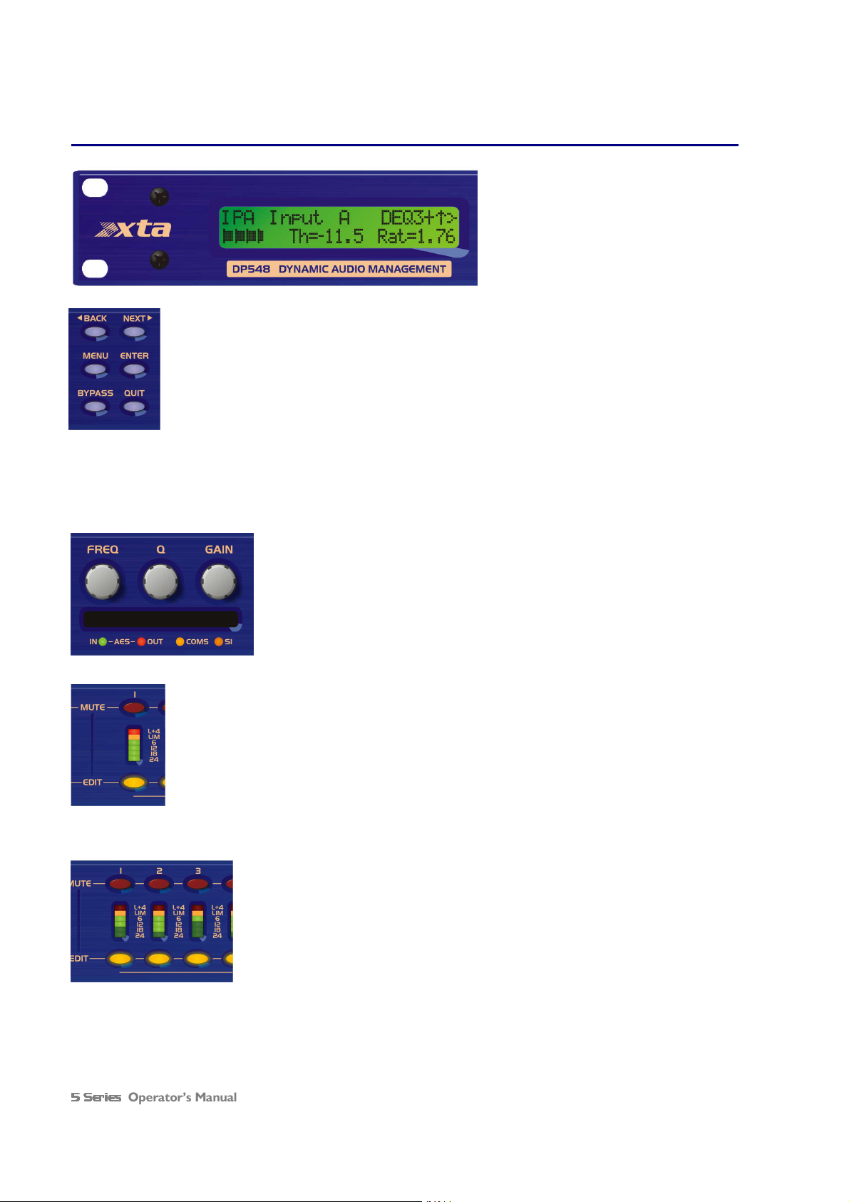
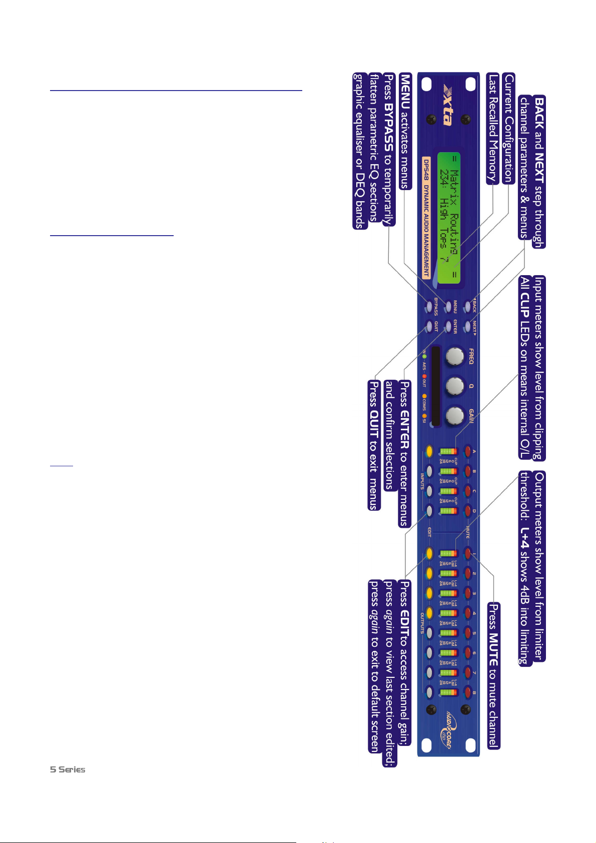
Front Panel Familiarisation
LCD Screen: Shows, by default, the name of the
last recalled memory on the bottom line of the
screen, and the current routing on the top line.
Also used to show all parameters as they are
edited, and all menu selections.
Control Keys: Selection and adjustment of parameters.
NEXT key moves forward through list of parameters.
BACK key moves backwards through list of parameters.
MENU key activates the main menu – a second press selects the last menu edited – a third press selects
the last menu item. In this way, three presses on MENU from the default screen will jump back to the
last parameter adjusted. Selection of different menus is accomplished using the BACK and NEXT keys,
or with the FREQ encoder.
ENTER key enters the chosen menu, confirms selections, and changes filter types when editing
parametric sections.
BYPASS will flatten the currently selected parametric sections, or input graphic equalisers and
dynamics modules. For safety reasons, it is not possible to bypass the high and low pass filter sections.
QUIT exits menus back to the default screen.
Rotary Encoders: Three velocity sensitive encoders adjust the relevant parameters as
displayed on the screen.
Memory Card Slot: Will accept type I or type II PCMCIA SRAM cards and, using an
adapter, Compact Flash cards. This allows the unit to be cloned, memory sets saved,
presets loaded, and firmware updates installed.
Status LEDs: The four status LEDs show, from left to right, AES inputs selected
(flashing if not locked); AES outputs selected; Comms activity (only illuminates on
messages addressed to this particular unit); and a general-purpose spare indicator.
Input Sections: Control and monitor input signal paths.
Red MUTE buttons illuminate when pressed and mute audio for that channel.
EDIT buttons illuminate yellow when pressed, and access gain on first press, then last viewed parameter
on second press, then exit on third press.
Input meters show dB from clipping point of the analogue to digital converters. Yellow (0dB) LED
illuminates 3dB from clipping. Red CLIP LED may illuminate independently from the rest of the meter
to show digital overflow. All four CLIP LEDs illuminating indicates internal clipping after the ADC.
Meters also read downwards from the yellow LED to show gain adjustment (reduction or expansion)
when editing DEQ modules – meter shows gain adjustment for current band of DEQ only.
Output Sections: Control and monitor output signal paths.
Red MUTE buttons illuminate when pressed and mute audio for that channel.
EDIT buttons illuminate yellow when pressed, and access gain on first press, then last
viewed parameter on second press, then exit on third press. Output meters show dB from
limiting. The yellow LED illuminates at the onset of limiting. The red LED illuminates at
4dB into limiting (i.e. 4dB of gain reduction).
Meters also read downwards from the yellow LED to show gain reduction when editing
compressors. These may be left permanently enabled by changing this option in the
DYNAMICS
DYNAMICS sub-menu.
DYNAMICSDYNAMICS
Operator’s Manual Page 11
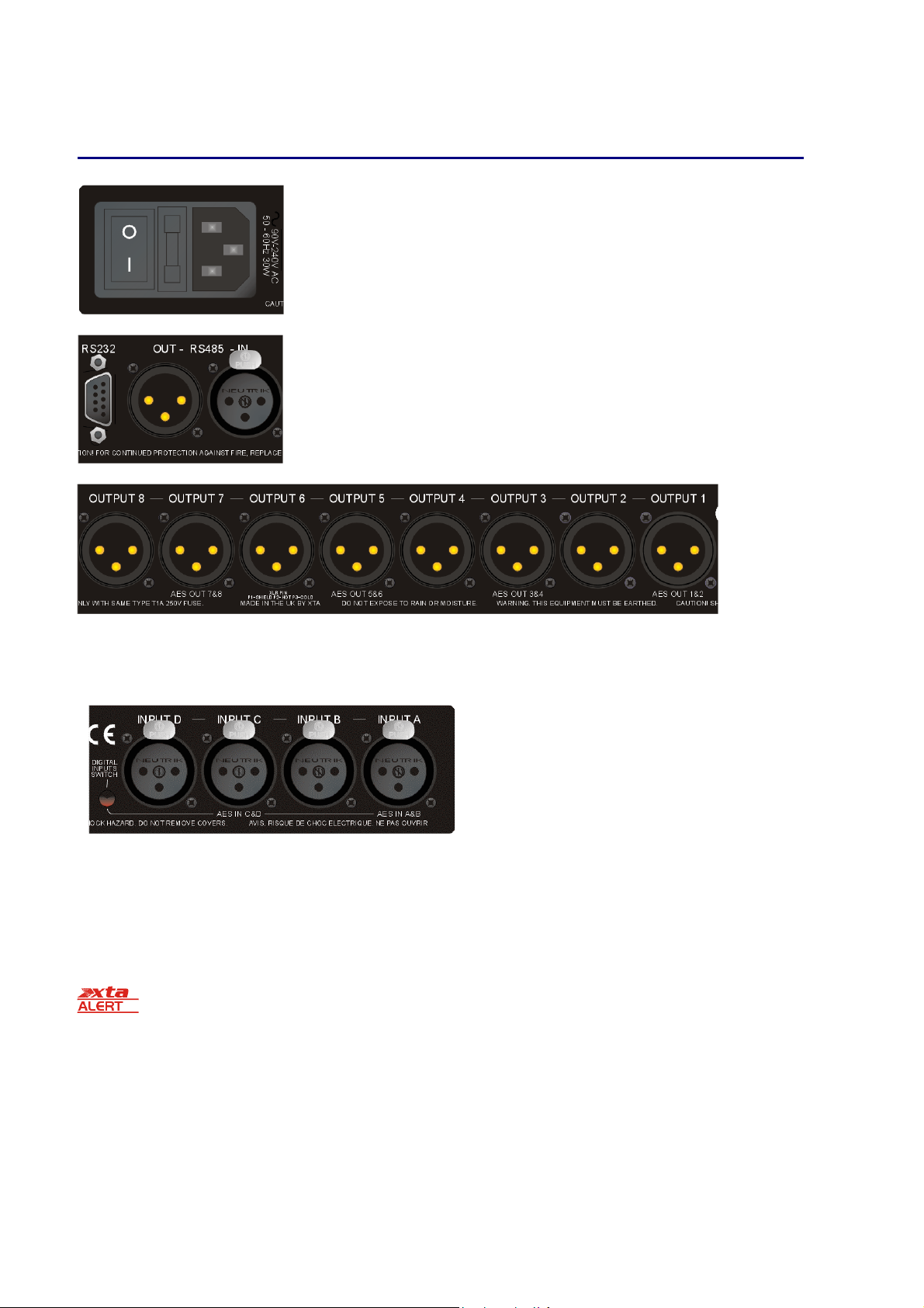
Rear Panel Connections
Power Switch: turns the unit’s mains supply off and on.
Mains Fuse: located in a finger-proof holder adjacent to the mains inlet. A spare fuse
is also located in this holder.
Mains Inlet: connected via a standard IEC socket.
RS232: RS232 standard via a 9 pin D-type connector, for connection to a PC. Data is
converted to RS485 standard and relayed to slave units via the RS485 sockets.
RS485 In-Out: XLR sockets. Used for transmission of remote control data over long
distance or multiple unit applications. See page 33 for more information.
For more details on interfaces see our Remote Interface Guide, available on-line.
Audio Outputs: 3 pin XLR sockets are provided for each channel. All are fully balanced, pin 2 hot, 3 cold, 1 screen.
Note the legending on the panel to designate which outputs are used for AES streams when the digital outputs are
enabled. Please see page 36 for more information.
Always replace the fuse with the correct type and rating as shown on the rear panel legend.
AES Input Switch: Recessed switch to select AES digital
inputs. Red LED will illuminate in the hole when AES inputs
are selected, along with the corresponding front panel
indicator.
Audio Inputs: 3 pin XLR sockets are provided for each
channel. All are fully balanced, pin 2 hot, 3 cold, 1 screen.
Note the legending on the panel to designate which inputs
are used for AES when the digital inputs are enabled. Please
see page 36 for more information.
Page 12 5 Series
5 Series Operator’s Manual
5 Series 5 Series

Operating the 5 Series
5 Series
5 Series5 Series
Note about operation with AudioCore software.
The following operating information covers setup and control of a 5 Series via the front panel controls only. Please
consult the manual supplied with this software for information regarding full computer control.
Start-up procedure
Switching on the unit will display a brief message detailing the unit type and software version running
== AudioCore DP548 ==
== AudioCore DP548 ==
== AudioCore DP548 ==== AudioCore DP548 ==
==Software V 1.00 ==
==Software V 1.00 ==
==Software V 1.00 ====Software V 1.00 ==
and all LEDs will briefly illuminate. The unit will then begin its countdown to the wake-up procedure2, during which time
the audio will fade up to the level last set. Metering will begin to operate when the fade-up starts.
Preliminary Set-up as a Crossover (DP548 & DP544)
The procedure below should be followed when first installing a 5 Series
5 Series unit as a crossover.
5 Series 5 Series
Design your crossover! To do this, press MENU, and use the BACK or NEXT key to select ‘Crossover
sub
sub----menu
menu’ and then press ENTER. Use the BACK or NEXT key to select ‘Design a crossove
subsub
menumenu
Design a crossoverrrr’
Design a crossoveDesign a crossove
Crossover
Crossover Crossover
and then press ENTER. Finally, use the BACK or NEXT key to select the desired routing3and follow the set-up
wizard to finalise your design.
Note that when in a menu, ENTER is always used to confirm selections. The current selection is marked with an
asterisk ‘*’.
Use the EDIT keys on each output channel with the BACK and NEXT keys to select the high pass filters, low
pass filters, parametrics etc. Note that when designing a new crossover, the high and low pass filters will be set
to default values.
Use the EDIT keys on each input channel with the BACK and NEXT keys to select the gain, delay and
parametrics available on each input.
Preliminary Set-up as Insert Channel Processing (DP544)
Follow the steps above, but choose 4 x 1 way as the desired routing – this will feed input A to output 1, input B to output
2 etc. so offering four independent channels of processing.
Note that if no action is taken in menu mode, the unit will return to normal ‘default’ mode after about twenty
(20) seconds. Repeat the above directions to return to menu mode.
2
The wake-up time countdown may be adjusted in the SYSTEM menu – see page 24 for details.
3
For details about adjusting the routing if one of the standard configurations does not suit, see page 15.
Operator’s Manual Page 13
Routing Options and Processing Blocks
Due to the completely new DSP platform, the routing possibilities within the 5 Series have been made completely
flexible, with a matrix available allowing any combination of inputs to be routed to any output. The additional DSP power
has permitted the inclusion of more processing blocks, even considering the extra inputs and outputs, and the doubling of
sample rate.
To reduce set-up time and aid usability, several standard configurations are available as described in a later section.
This section will outline the processing blocks available in relation to the signal path, and explain the various options for
routing, including the “Free Assign” mode, which opens up completely flexible channel routing, and “Matrix” mode which
also adds gain controls for mixing capabilities.
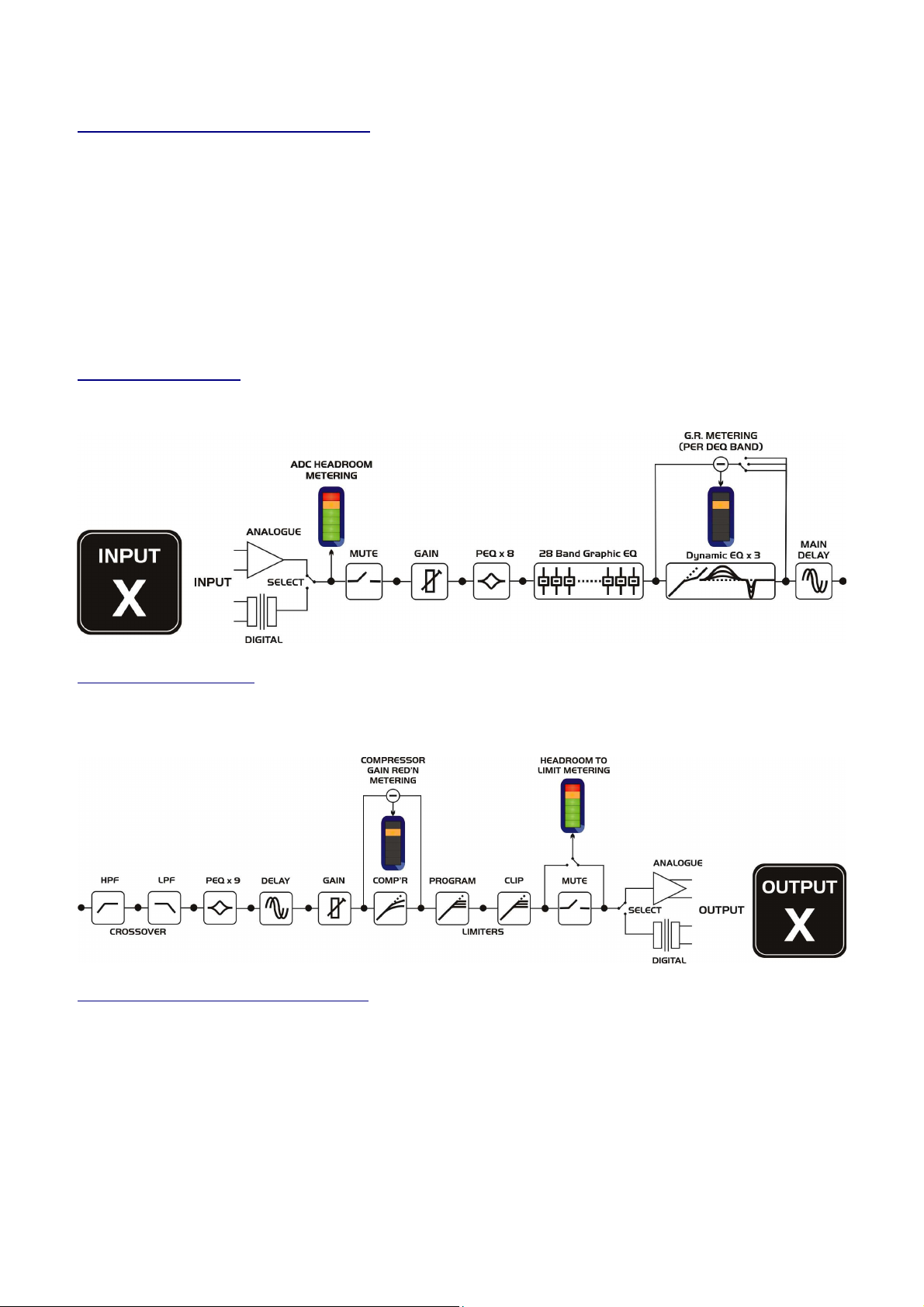
Input Channel Makeup
The diagram below shows the processing available on each of the four input channels, before routing to the matrix.
Output Channel Makeup
The diagram below shows the processing available on each of the eight output channels, after routing from the
matrix/mixer.
Preset Routing Configurations: DP548
In addition to the ability to assign any combination of inputs to any output, a number of preset configurations are provided,
for use when designing a crossover from scratch. These have the advantage of suggested settings for the high and low pass
filters to useful basic starting points, to filter the different outputs as appropriate for the chosen configuration. These may,
of course, be freely modified afterwards should they not suit the requirements exactly.
The diagrams on the following pages show the connections made between inputs and outputs, and the suggested values
chosen for the high and low pass filters.
Page 14 5 Series
5 Series Operator’s Manual
5 Series 5 Series
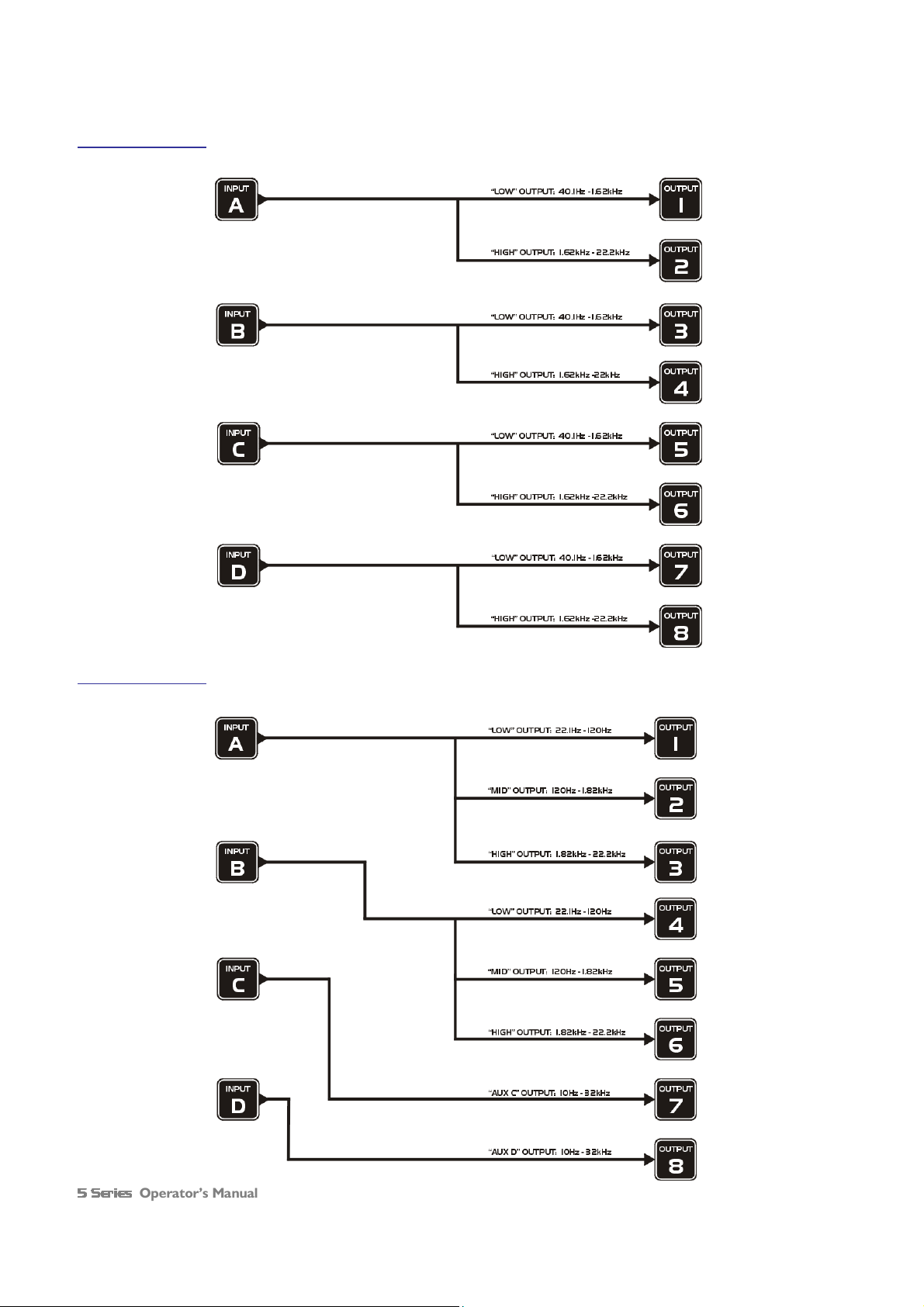
4 x 2 way crossover: As shown, each input feeds a pair of outputs, odd numbers being the low frequency split, and even
numbers being the high part of the spectrum. Default suggested crossover frequencies are shown by each output.
2 x 3 way crossover: Inputs A and B feed three outputs each, with output 7 being fed from input C, and output 8 from
input D. Note the ‘Aux’ outputs are set to full range. Default suggested crossover frequencies are shown by each output.
Operator’s Manual Page 15
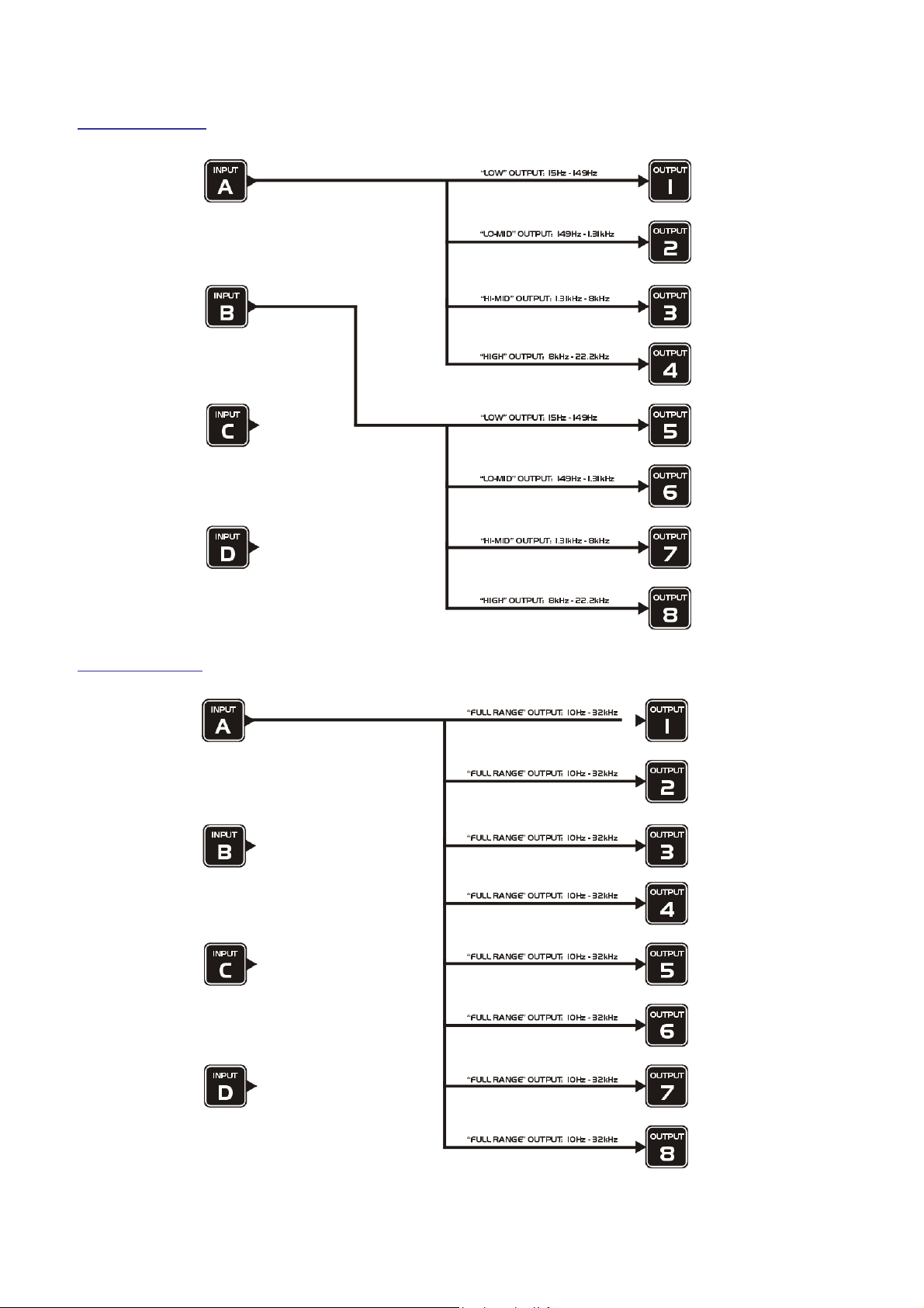
2 x 4 way crossover: Inputs A and B feed four outputs each, with inputs C & D being unused. Default suggested crossover
frequencies are shown by each output.
1 x 8 way crossover: Inputs A is fed to all eight outputs, with initial settings being all full bandwidth. The crossover points
can be adjusted as desired.
Page 16 5 Series
5 Series Operator’s Manual
5 Series 5 Series
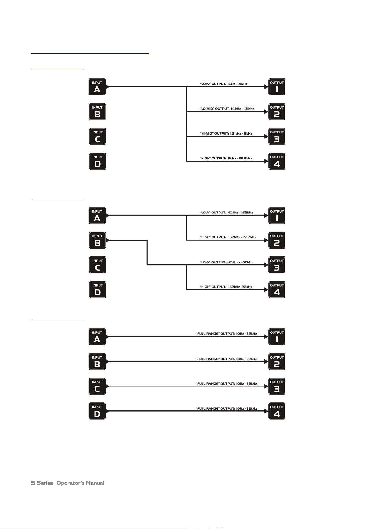
Preset Routing Configurations: DP544
1 x 4 way crossover: Input A is routed to all four output, with default crossover points shown. Inputs B – D are muted.
2 x 2 way crossover: Input A is routed to outputs 1 & 2, input B to 3 & 4. Inputs C & D are muted.
4 x 1 way crossover: Each input is routed to a corresponding output A to 1, B to 2 etc. Crossovers filters are bypassed.
Operator’s Manual Page 17
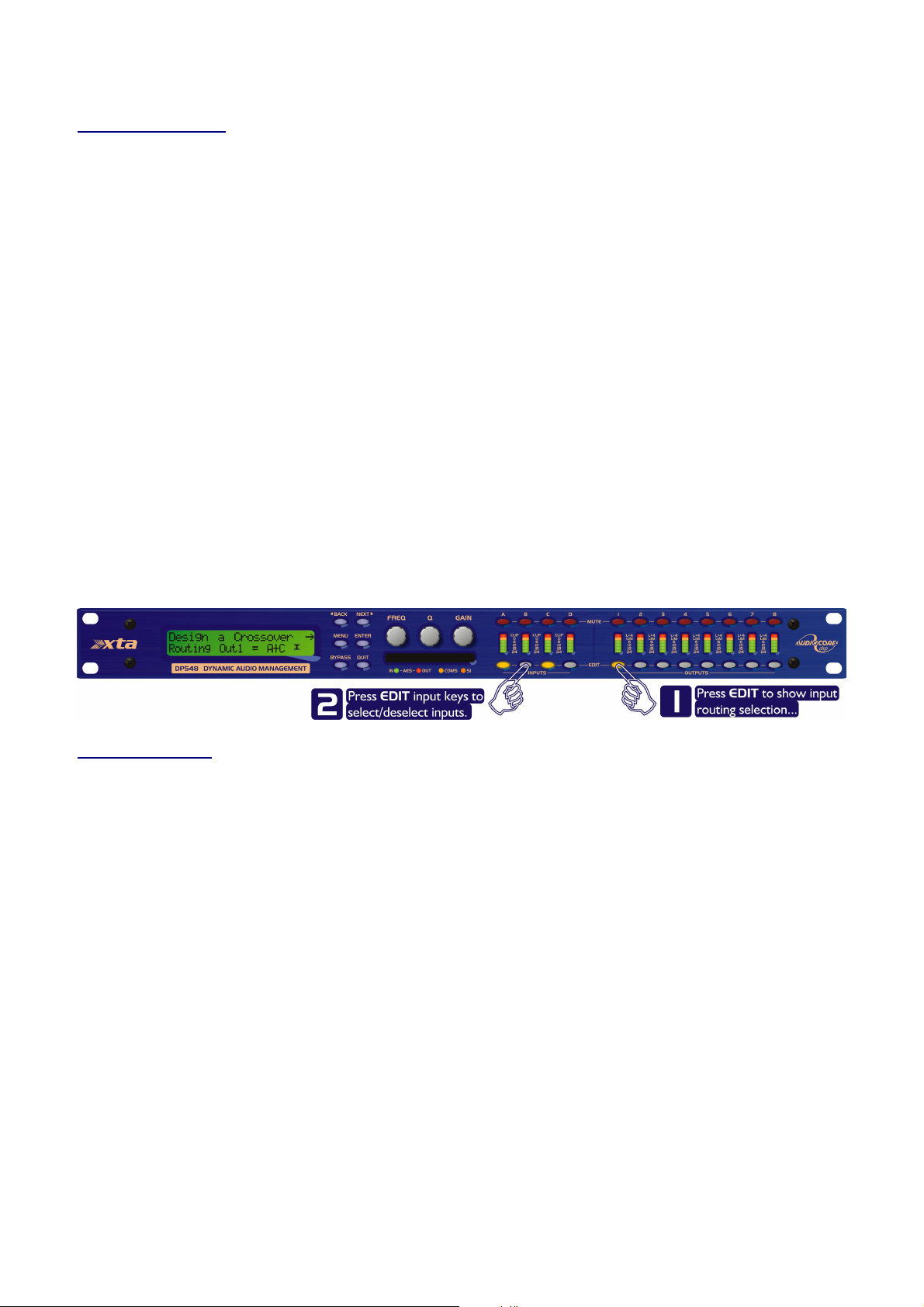
Free Assign Routing
If none of the preset configurations are appropriate to the required system setup, it is possible to manually select the
routing of the crossover. This is achieved through the Crossover Menu
Pressing ENTER will start the crossover design wizard, with the first option being to choose the routing.
The display will show
Design A
Design A Crossover
Design ADesign A
Routing = 2 X 4 WAY *
Routing = 2 X 4 WAY *
Routing = 2 X 4 WAY *Routing = 2 X 4 WAY *
or whatever the current configuration is set to. Press BACK until the display shows
Design A Crossover
Design A Crossover ---->>>>
Design A Crossover Design A Crossover
Routing = Free Assign
Routing = Free Assign
Routing = Free AssignRouting = Free Assign
And then press ENTER. The EDIT key will illuminate for output 1, as will any relevant input EDIT keys, showing which
inputs are feeding output 1. The display will also detail the current combination of inputs feeding this output. To change
the routing for any output, press its EDIT key, and then choose the required input channel combination by just pressing
the input EDIT keys as appropriate. The input combinations can also be stepped through in turn by pressing NEXT, or
BACK.
To complete the procedure, press ENTER. The wizard will continue, and if the routing has been changed, all outputs will
be muted on exit.
Crossover Menu ----> Design A Crossover
Crossover Menu Crossover Menu
Crossover ---->>>>
Crossover Crossover
> Design A Crossover.
> Design A Crossover> Design A Crossover
Full Matrix Mixing
If the free assign mode still isn’t flexible enough (!), it is possible to manually select the routing of the crossover with full
level mixing from any input to output. This is achieved through the
Cr
Crossover Menu
ossover Menu ----> Design A Crossover
CrCr
Pressing ENTER will start the crossover design wizard, with the first option being to choose the current routing.
The display will show
or whatever the current configuration is set to. Press BACK until the display shows
To complete the procedure, press ENTER. The wizard will continue, and if the routing has been changed, all outputs will
be muted on exit.
Matrix routing levels are stored in crossover memories (as with routing settings).
ossover Menu ossover Menu
Design A Crossover
Design A Crossover ---->>>>
Design A Crossover Design A Crossover
Routing = 2 X 4 WAY *
Routing = 2 X 4 WAY *
Routing = 2 X 4 WAY *Routing = 2 X 4 WAY *
Design A Crossover
Design A Crossover ---->>>>
Design A Crossover Design A Crossover
Routing = Full Matrix
Routing = Full Matrix
Routing = Full MatrixRouting = Full Matrix
> Design A Crossover
> Design A Crossover> Design A Crossover
Page 18 5 Series
5 Series Operator’s Manual
5 Series 5 Series

Editing Audio Parameters – Input Channels
Input Gain
The range of the control over the input gain is –40dB to +6dB in 0.1dB steps.
InA I
InA Input A Gain
InA IInA I
Input Gain = +6.0dB
Input Gain = +6.0dB
Input Gain = +6.0dBInput Gain = +6.0dB
nput A Gain
nput A Gainnput A Gain
Gain
Base Delay
The maximum available delay between any input and output is 650.00mS. For example, if the input delay on channel A is
set to 500mS, the maximum available output delay for any output fed from input A will be 150mS. The readout units can
be changed between time in milliseconds, distance in feet or distance in metres. Please see page 27 for more details.
IIIInA Input A Delay
nA Input A Delay
nA Input A DelaynA Input A Delay
Base Delay = 0.00mS
Base Delay = 0.00mS
Base Delay = 0.00mSBase Delay = 0.00mS
x 1mS x 10uS
343mm 4mm
Note that Base Delay (Input Delay) is not available when in “Full Matrix” mode.
Input Graphic EQ
The graphic equaliser has 28 third octave bands from 31Hz to 16kHz, and a gain range of +12dB. The G6
line of the screen denotes the ‘Q’ behaviour of the graphic – this setting behaves like a GQ600 with variable ‘Q’ that is
‘gentler’ at low cut/boost values and sharpens at high cut/boost values. The alternate setting, Sp
behaviour where no change in bandwidth occurs with differing cut/boost. Pressing BYPASS
BYPASS will bypass the entire
BYPASSBYPASS
Sp, is a constant ‘Q’
SpSp
Graphic EQ on this channel. For details of how to select the behaviour, please see page 27.
InA Input A Graph<>
InA Input A Graph<>
InA Input A Graph<>InA Input A Graph<>
40Hz +
40Hz +-----
40Hz +40Hz +
-----
G6 0.0dB
----------
G6 0.0dB
G6 0.0dBG6 0.0dB
G6 on the second
G6G6
Frequency Gain
Input Parametric EQ
There are eight bands of parameter equalisation available on every input. The behaviour of each individual band can be
changed to a variety of different filter shapes, including high and low shelves, notch, and bandpass. Changing the filter type
is achieved by pressing ENTER
available, please see page 55.
Operator’s Manual Page 19
ENTER during editing any particular band. For more details about the various types of filter
ENTER ENTER
InA Input A PEQ:1<>
InA Input A PEQ:1<>
InA Input A PEQ:1<>InA Input A PEQ:1<>
1k00Hz Q=3.0 0.0dB
1k00Hz Q=3.0 0.0dB
1k00Hz Q=3.0 0.0dB1k00Hz Q=3.0 0.0dB
Frequency ‘Q’ Gain

Input Dynamic EQ
There are 3 bands of dynamic EQ available on each input. Each band has three screens associated with it. For more
information on how the dynamic EQ works, please see page 44. The first edit screen shows the threshold for the band,
and the ratio for the dynamic action, along with the mode. The gain reduction meter to the left on the bottom line of the
display shows gain reduction (or expansion) in 0.5dB steps. The band can by bypassed by pressing the BYPASS
whereupon the meter will be replaced by BYPASS
BYPASS.
BYPASSBYPASS
InA Input A DEQ1+^X
InA Input A DEQ1+^X
InA Input A DEQ1+^XInA Input A DEQ1+^X
|||||||||| Th=
|||||||||| Th=----32.0 Rat=2.00
|||||||||| Th=|||||||||| Th=
Threshold Ratio
Threshold Ratio
Threshold RatioThreshold Ratio
32.0 Rat=2.00
32.0 Rat=2.0032.0 Rat=2.00
BYPASS key
BYPASSBYPASS
Mode is indicated at the right hand side of the top line like this “DEQ1+↑X”. In this case it represents “Boost Above”
mode, with the X showing the filter type – parametric, high or low shelf or full bandwidth. The plus or minus shows boost
or cut and the arrow shows above or below the threshold (↓). Filter type is changed by setting the ratio to 1:1 (or
pressing BYPASS
shelving filters and the full bandwidth mode (compressor or expander), please see page 49.
Pressing NEXT
the ratio to 1:1 and then turning the left encoder. Note that release time cannot be set to faster than the attack time and
will be forced to track it if you increase the attack to a greater value than the release. This is to prevent introducing
distortion that can be caused due to the detector tracking individual cycles of the waveform, rather than its envelope.
There is more information about this in the section on page 50.
BYPASS) and then pressing ENTER
BYPASSBYPASS
NEXT shows the attack and release times, alongside the operating mode. The mode can be changed by setting
NEXTNEXT
ENTER to scroll through the types. For more information about the use of the
ENTERENTER
InA Input A DEQ1+^X
InA Input A DEQ1+^X
InA Input A DEQ1+^XInA Input A DEQ1+^X
BstAbv At=0.07mS Rl=11mS
BstAbv At=0.07mS Rl=11mS
BstAbv At=0.07mS Rl=11mSBstAbv At=0.07mS Rl=11mS
Mode Attack Release
Mode Attack Release
Mode Attack ReleaseMode Attack Release
Pressing NEXT
allowable amount of gain change that may be applied – so even if the signal is far over the threshold with a high ratio, the
gain of the band won’t change by more than this value.
Page 20 5 Series
NEXT shows the filter parameters for the band. Note that gain value shown is the maximum (or minimum)
NEXTNEXT
InA Input A DEQ1+^X
InA Input A DEQ1+^X
InA Input A DEQ1+^XInA Input A DEQ1+^X
99.2Hz 1.0 12dB
99.2Hz 1.0 12dB
99.2Hz 1.0 12dB99.2Hz 1.0 12dB
Frequency ‘Q’ Max. Gain
Frequency ‘Q’ Max. Gain
Frequency ‘Q’ Max. GainFrequency ‘Q’ Max. Gain
5 Series Operator’s Manual
5 Series 5 Series

Editing Audio Parameters – Output Channels
Output Gain
The range of the control over the input gain is –40dB to +15dB in 0.1dB steps.
OP1 Output 1 Gain
OP1 Output 1 Gain
OP1 Output 1 GainOP1 Output 1 Gain
Output Gain = +6.0dB
Output Gain = +6.0dB
Output Gain = +6.0dBOutput Gain = +6.0dB
Gain
Output Polarity
The polarity (or phase) of each output may be switched individually as below.
OP1 Output 1 Polar.
OP1 Output 1 Polar.
OP1 Output 1 Polar.OP1 Output 1 Polar.
Polarity = [+]
Polarity = [+]
Polarity = [+]Polarity = [+]
- or +
Output Delay
The maximum available delay between any input and output is 650.00mS. For example, if the input delay on channel A is
set to 500mS, the maximum available output delay for any output fed from input A will be 150mS. The readout units can
be changed between time in milliseconds, distance in feet or distance in metres. Please see page 27 for more details.
OP1 Output 1 Delay
OP1 Output 1 Delay
OP1 Output 1 DelayOP1 Output 1 Delay
Delay = 0.0000mS
Delay = 0.0000mS
Delay = 0.0000mSDelay = 0.0000mS
x 1mS x 10uS x0.3uS
343mm 4mm 0.1mm
Operator’s Manual Page 21

Output High Pass Filter
The high pass crossover filter on each output has a frequency range of <10Hz up to 32kHz in 1/36th Octave steps. If you
try to set the high pass filter to a higher frequency than the low pass (which would be pointless and result in no output),
the message High/Low Freq. Overlap!
parametric bands 6 & 7 need to be bypassed, or set to 0dB. If they are not, the message Bypass PEQ’s 6
7 To Access 48dB Slopes
7 To Access 48dB Slopes will be displayed.
7 To Access 48dB Slopes 7 To Access 48dB Slopes
High/Low Freq. Overlap! will be displayed. Note that to access the 48dB/Octave filters,
High/Low Freq. Overlap!High/Low Freq. Overlap!
Bypass PEQ’s 6 &
Bypass PEQ’s 6 Bypass PEQ’s 6
OP1 Output 1 HPF /~~
OP1 Output 1 HPF /~~
OP1 Output 1 HPF /~~OP1 Output 1 HPF /~~
<10Hz Linkw
<10Hz Linkw----Riley 48dB
<10Hz Linkw<10Hz Linkw
Riley 48dB
Riley 48dBRiley 48dB
&
& &
Frequency Slope
Output Low Pass Filter
The low pass crossover filter on each output has a frequency range of 35.1Hz up to >32kHz in 1/36th Octave steps. If you
try to set the low pass filter to a lower frequency than the high pass (which would be pointless and result in no output), the
message High/Low Freq. Overlap!
parametric bands 8 & 9 need to be bypassed, or set to 0dB. If they are not, the message Bypass PEQ’s 8 &
9 To Access 48dB Slopes
9 To Access 48dB Slopes will be displayed.
9 To Access 48dB Slopes9 To Access 48dB Slopes
High/Low Freq. Overlap! will be displayed. Note that to access the 48dB/Octave filters,
High/Low Freq. Overlap!High/Low Freq. Overlap!
Bypass PEQ’s 8 &
Bypass PEQ’s 8 & Bypass PEQ’s 8 &
OP1 Output 1 LPF ~~
OP1 Output 1 LPF ~~\\\\
OP1 Output 1 LPF ~~OP1 Output 1 LPF ~~
>32kHz Linkw
>32kHz Linkw----Riley 48dB
>32kHz Linkw>32kHz Linkw
Riley 48dB
Riley 48dBRiley 48dB
Frequency Slope
Output Parametric EQ
There are nine bands of parametric equalisation available on every output4. The behaviour of each individual band can be
changed to a variety of different filter shapes, including high and low shelves, notch, and bandpass. Changing the filter type
is achieved by pressing BYPASS
more details about the various types of filter available, please see page 55.
BYPASS to bypass the filter and then pressing ENTER
BYPASSBYPASS
OP1 Output 1 PEQ:1<>
OP1 Output 1 PEQ:1<>
OP1 Output 1 PEQ:1<>OP1 Output 1 PEQ:1<>
1k00Hz Q=3.0 0.0dB
1k00Hz Q=3.0 0.0dB
1k00Hz Q=3.0 0.0dB1k00Hz Q=3.0 0.0dB
ENTER during editing any particular band. For
ENTER ENTER
Frequency ‘Q’ Gain
4
Note that 2 bands each will be lost when using 48dB slope crossover filters, resulting in a maximum of 5 bands of EQ
when both high and low pass are set to 48dB/Octave.
Page 22 5 Series
5 Series Operator’s Manual
5 Series 5 Series

Output Compressor
The compressor on each output has adjustable attack and threshold, with a variable knee control that can be set to hard
(0) so the onset of compression happens exactly at the threshold, or “softened” (up to 12) where compression starts
below the threshold and gradually reaches full effect above the threshold. More information about the knee control is
given on page 51.
The gain reduction meter to the left on the bottom line of the display shows gain reduction (or expansion) in 0.5dB steps.
The band can by bypassed by pressing the BYPASS
BYPASS key whereupon the meter will be replaced by BYPASS
BYPASSBYPASS
OP1 Output 1 Compress
OP1 Output 1 Compress
OP1 Output 1 CompressOP1 Output 1 Compress
|||||||||
||||||||| ----22dB R=1.03 K=12
||||||||| |||||||||
22dB R=1.03 K=12
22dB R=1.03 K=1222dB R=1.03 K=12
BYPASS.
BYPASSBYPASS
Threshold Ratio Knee
Pressing NEXT
and will be forced to track it if you increase the attack to a greater value than the release. This is to prevent introducing
distortion that can be caused due to the detector tracking individual cycles of the waveform, rather than its envelope. For
more information about this, see the section about the compressors on page 48.
NEXT shows the attack and release times. Note that release time cannot be set to faster than the attack time
NEXTNEXT
The attack and release times can be automatically linked to the high pass filter frequency, so that they are set to correct
values for the output’s frequency range. If this feature is enabled, the display will show Automatic T/C
the attack and release times. Selection of automatic time constants is through the Design a Crossover
in the Crossover Sub
Crossover Sub----Menu
Crossover SubCrossover Sub
Menu.
MenuMenu
Automatic T/C in place of
Automatic T/CAutomatic T/C
Design a Crossover wizard,
Design a CrossoverDesign a Crossover
OP1 Output 1 Compress
OP1 Output 1 Compress
OP1 Output 1 CompressOP1 Output 1 Compress
|||||||||||| At=00.07mS Rl=45mS
|||||||| At=00.07mS Rl=45mS
|||||||| At=00.07mS Rl=45mS|||||||| At=00.07mS Rl=45mS
Attack Release
Operator’s Manual Page 23

Output Limiter
The limiter on each output has adjustable attack and threshold, with a release time that is selectable to be a multiplier of
the attack time. For example, as shown below, the attack time is 2mS and release is “x16” so 32mS. The attack and
release times can be automatically linked to the high pass filter frequency, so that they are set to correct values for the
output’s frequency range. If this feature is enabled, the display will show Automatic T/C in
and release times. Selection of automatic time constants is through the Design a Crossover
Crossover Sub
Crossover Sub----Menu
Crossover SubCrossover Sub
Menu.
MenuMenu
OP1 Out
OP1 Output 1 Limiter
OP1 OutOP1 Out
Atk=2.0mS Rel=x16 +22dB
Atk=2.0mS Rel=x16 +22dB
Atk=2.0mS Rel=x16 +22dBAtk=2.0mS Rel=x16 +22dB
put 1 Limiter
put 1 Limiterput 1 Limiter
Automatic T/C in place of the attack
Automatic T/C inAutomatic T/C in
Design a Crossover wizard, in the
Design a CrossoverDesign a Crossover
Attack Release Threshold
Output “D-Max” (Clip) Limiter
The clip limiter on each output is designed to sit at a threshold just above the standard limiter and has a look ahead attack
so that its threshold can never be exceeded. The release time can be automatically linked to the high pass filter frequency,
so that it is set to a value appropriate for the output’s frequency range. If this feature is enabled, the display will show
Rel. = Auto
Rel. = Auto in place of the release time. Selection of automatic time constants is through the
Rel. = AutoRel. = Auto
Design a Crossover
Design a Crossover wizard, in the Crossover Sub
Design a CrossoverDesign a Crossover
More information about the limiters and their use is given in the section on page 44.
OP1 Output 1 ClipLim
OP1 Output 1 ClipLim
OP1 Output 1 ClipLimOP1 Output 1 ClipLim
Release Threshold
Output Matrix Mixing
If “full matrix” mode has been enabled (selection of this is through the Design a Crossover
Crossover Sub
Crossover Sub----Menu
Crossover SubCrossover Sub
Menu) this screen will be shown after the limiters when editing outputs.
MenuMenu
Crossover Sub----Menu
Crossover SubCrossover Sub
Rel.=Medium 2dB Above
Rel.=Medium 2dB Above
Rel.=Medium 2dB AboveRel.=Medium 2dB Above
OP1 Matrix Gain A
OP1 Matrix Gain A
OP1 Matrix Gain AOP1 Matrix Gain A
[+14.5] Off Off
[+14.5] Off Off ----32.8
[+14.5] Off Off [+14.5] Off Off
Menu.
MenuMenu
Design a Crossover wizard, in the
Design a CrossoverDesign a Crossover
32.8
32.832.8
Gain
Selection of the “send” to this output (cycling between inputs A-D) is achieved by pressing ENTER
change to show the relevant send channel for adjustment (Gain A
bracketed on the bottom line. The gain control will adjust the level to be mixed into this output. One click below
minimum gain (----40dB
Note that ganging is temporarily disabled when the matrix sends screen is shown.
Page 24 5 Series
40dB) will mute the send and the gain will be replaced by Off
40dB40dB
Gain A----DDDD) and the mix level to adjust will become
Gain AGain A
ENTER – the top line will
ENTERENTER
Off as shown above.
Off Off
5 Series Operator’s Manual
5 Series 5 Series

Input Ganging and Output Ganging
The method of linking inputs or outputs together during editing is achieved in the same way, so only crossover (output)
ganging will be explained here. Having selected Crossover Ganging
Sub
Sub----Menu
Menu, the current ganging set-up will be displayed. This will either be a preset selection as would be useful in a
SubSub
MenuMenu
standard crossover configuration – for example
…would be a logical ganging arrangement if the crossover was set up as a 4 x 2 way – linking the control and adjustment of
all “Low” outputs together, and that of all “High” outputs together.
However, if the crossover has not been set up with a preset routing configuration, then it may be required to set up the
ganging to compliment this configuration. This is achieved using the Free Assign
preset ganging choices, which are:
Selecting Free Assign
Free Assign and then pressing ENTER will begin the process of ganging outputs together using the
Free Assign Free Assign
following simple rules:
All outputs are ganged to the lowest number – so to gang 3 & 5, 5 must be selected and then ganged to 3.
Outputs cannot share more than one ganging set – so for example output 3 cannot be ganged to 2 and 4 unless
they are ganged together as well. (Effectively 3 and 4 are ganged to 2 in this case)
Crossover Ganging from the menu under the Cros
Crossover GangingCrossover Ganging
<<<<----Crossover Ganging
Crossover Ganging
Crossover GangingCrossover Ganging
Ganging=1+3+5+7 2+4+6+8
Ganging=1+3+5+7 2+4+6+8
Ganging=1+3+5+7 2+4+6+8Ganging=1+3+5+7 2+4+6+8
Crossover
CrosCros
Free Assign mode. This is selected from the
Free AssignFree Assign
Ganging=None
Ganging=None [all outputs independent]
Ganging=NoneGanging=None
Ganging=Free Assign
Ganging=Free Assign [choose ganging]
Ganging=Free AssignGanging=Free Assign
Gangin
Ganging=1+2+3+4+5+6+7+8
GanginGangin
Ganging=1+5 2+6 3+7 4+8
Ganging=1+5 2+6 3+7 4+8 [4 x 2 way]
Ganging=1+5 2+6 3+7 4+8Ganging=1+5 2+6 3+7 4+8
Ganging=1+3+5+7 2+4+6+8
Ganging=1+3+5+7 2+4+6+8 [2 x 4 way]
Ganging=1+3+5+7 2+4+6+8Ganging=1+3+5+7 2+4+6+8
g=1+2+3+4+5+6+7+8 [1 x 8 way]
g=1+2+3+4+5+6+7+8g=1+2+3+4+5+6+7+8
sover
sover sover
With these rules in mind, selecting and setting up gangs is quite straightforward.
Press a MUTE key to choose the output to gang – its LED will begin to flash, and an EDIT key will illuminate to show
which output it is currently ganged with. To change this selection, just press another EDIT key, remembering that gangs
work from the highest to lowest number. So, to gang outputs 1 and 5, press MUTE 5 then EDIT 1 – the display will show
<<<<----Crossover Ganging
Crossover Ganging
Crossover GangingCrossover Ganging
Gang Output 5 with 1
Gang Output 5 with 1
Ganging is cleared by selecting Ganging=None
Ganging=None from the initial choices given above. The Input Ganging
Ganging=NoneGanging=None
procedure is identical to the crossover ganging, selectable under the Input Sub
Gang Output 5 with 1Gang Output 5 with 1
Input Sub----Menu
Input SubInput Sub
Menu.
MenuMenu
Input Ganging
Input Ganging Input Ganging
Please note that ganging options shown above refer to the DP548 – the DP544 will obviously not have options for ganging
outputs 5 to 8!
Operator’s Manual Page 25

Menu System Shortcuts
A lot of functions have been assigned menu shortcuts – these are accessible directly from the default screen by pressing
MENU
MENU followed by the appropriate MUTE
MENUMENU
given below.
Store Graphic Memory
Store Graphic Memory
Store Graphic MemoryStore Graphic Memory
Store Input Memory
Store Input Memory
Store Input MemoryStore Input Memory
Store Crossover Memory
Store Crossover Memory
Store Crossover MemoryStore Crossover Memory
Store Last Memory Type
Store Last Memory Type
Store Last Memory TypeStore Last Memory Type
Recall Graphic Memory
Recall Graphic Memory
Recall Graphic MemoryRecall Graphic Memory
Recall Input
Recall Input Memory
Recall Input Recall Input
Recall Crossover Memory
Recall Crossover Memory
Recall Crossover MemoryRecall Crossover Memory
Recall Last Memory Type
Recall Last Memory Type
Recall Last Memory TypeRecall Last Memory Type
System Status
System Status
System StatusSystem Status
External Interface Set
External Interface Set----up
External Interface SetExternal Interface Set
Change Graphic Q/Bandwidth
Change Graphic Q/Bandwidth
Change Graphic Q/BandwidthChange Graphic Q/Bandwidth
MUTE or EDIT
MUTEMUTE
EDIT button as shown. The entire list of features accessible in this way is
EDITEDIT
Memory
MemoryMemory
up
upup
Filter Q/Bandwidth Display Readout
Filter Q/Bandwidth Display Readout
Filter Q/Bandwidth Display ReadoutFilter Q/Bandwidth Display Readout
Delay Units Time/Distance Readout
Delay Units Time/Distance Readout
Delay Units Time/Distance ReadoutDelay Units Time/Distance Readout
AES Input Status
AES Input Status
AES Input StatusAES Input Status
Dynamic EQ Neters
Dynamic EQ Neters
Dynamic EQ NetersDynamic EQ Neters
Compres
Compressor Meters
Some of these shortcuts are not available on the DP544 due to the output buttons for channel 5-8 being absent!
CompresCompres
Design a Crossover
Design a Crossover
Design a CrossoverDesign a Crossover
Input Ganging
Input Ganging
Input GangingInput Ganging
Crossover (Output) Ganging
Crossover (Output) Ganging
Crossover (Output) GangingCrossover (Output) Ganging
Input Reset
Input Reset
Input ResetInput Reset
Unit Locking
Unit Locking
Unit LockingUnit Locking
AES Output Mode
AES Output Mode
AES Output ModeAES Output Mode
-----
-----
----------
-----
sor Meters
sor Meterssor Meters
Page 26 5 Series
5 Series Operator’s Manual
5 Series 5 Series

Menus in Detail
Recall Graphic, Input and Crossover Memories or combinations of.
Store Graphic, Input and Crossover Memories or combinations of.
Erase Graphic, Input and Crossover Memories or combinations of.
Gang (link) inputs together so their parameters track.
Start wizard to reset sections of input parameters, including graphics.
Select between ‘GQ600’ and other graphic behaviours.
Set up a new crossover from scratch. This selection starts a wizard to guide through the
Gang (link) outputs together so their para
meters track.
Starts a wizard to configure the baud rate, ID and port selection of the remote interface.
Configures wireless interface (if connected).
Configure the GPI inputs used for
closed contact memory recall (hardware option).
Displays a series of information screens including software version, temperature,
Adjust the viewing angle of the screen.
Adjust the brightness of all the meters and button LEDs.
Set the threshold for the unit to flash a warning temperature message
on the screen.
Select this option to install new operating software
– see page
40 for more information.
Adjust the time before the audio fades in on start
-
up –
can also be set to keep mutes
on
Select the monitoring point for the meters
– either pre or post mute (so meters can be
Select the readout units for the ‘Q’ setting of parametric filters
– ‘Q’ is 1/Bandwidth (in
Select the readout units for all delay values
– either time, or distance in feet or metres.
Copy a unit’s complete setup, including mem
ories and all menu options using a PCMCIA
Load a new preset file from a PCMCIA card
Select the time that the input CLIP LEDs stay illuminat
ed for after an overload has
Adjust the real time clock settings.
Protect the unit against unauthorised access with a password
- please see page
38 for
GLOBA
GLOBAL MEM.
GLOBAGLOBA
Recall a Memory
Recall a Memory
Recall a MemoryRecall a Memory
Store a Memory
Store a Memory
Store a MemoryStore a Memory
Erase a Memory
Erase a Memory
Erase a MemoryErase a Memory
Design a Crosso ver
Design a Crosso ver
Design a Crosso verDesign a Crosso ver
Crossover Gangin g
Crossover Gangin g
Crossover Gangin gCrossover Gangin g
External Interfa ce
External Interfa ce
External Interfa ceE xternal Interface
Wiser 2400 Setu p
Wiser 2400 Setu p
Wiser 2400 Setu pWiser 2400 Setu p
Temperature Alar m
Temperature Alar m
Temperature Alar mTemperature Alar m
Filter Q/Bandwid th
Filter Q/Bandwid th
Filter Q/Bandwid thF ilter Q/Bandwidth
Set Date & Time
Set Date & Time
Set Date & TimeSet Date & Time
L MEM.
L MEM.L MEM.
INPUT
INPUT
INPUT INPUT
SECTION
SECTION
SECTIONSECTION
Input Ganging
Input Ganging
Input GangingInput Ganging
Input Reset
Input Reset
Input ResetInput Reset
Change Graphic
Change Graphic
Change Graphic Change Graphic
Q/BW
Q/BW
Q/BWQ/BW
CROSS
CROSSOVER
CROSSCROSS
INTERFACE
INTERFACE
INTERFACEINTERFACE
GPI Interface
GPI Interface
GPI InterfaceGPI Interface
SYSTEM
SYSTEM
SYSTEMSYSTEM
System Status
System Status
System StatusSystem Status
LCD Contrast
LCD Contrast
LCD ContrastLCD Contrast
LED Brightness
LED Brightness
LED BrightnessLED Brightness
Program Update
Program Update
Program UpdateProgram Update
Wake
Wake----up Time
WakeWake
OVER
OVEROVER
up Time
up Timeup Time
process. Also select this to alter the set-up of the current crossover.
hardware and firmware versions, date and time. Press NEXT
when powered up.
Output Meters
Output Meters
Output Meters Output Meters
Opt’n
Opt’n
Opt’nOpt’n
Delay
Delay
Delay Delay
Time/Dist’nce
Time/Dist’nce
Time/Dist’nceTime/Dist’nce
Unit Cloning
Unit Cloning
Unit CloningUnit Cloning
set to work even when outputs muted)
octaves) – small ‘Q’ values mean wide response variations.
card. See page 38 for more information on card types.
Preset Update
Preset Update
Preset UpdatePreset Update
Clip LED Hold
Clip LED Hold
Clip LED Hold Clip LED Hold
Time
Time
TimeTime
SECURITY
SECURITY
SECURITYSECURITY
Unit Locking
Unit Locking
Unit LockingUnit Locking
passed.
more details.
NEXT to jump through info.
NEXTNEXT
Operator’s Manual Page 27

Switch the outputs of the unit to digital. (Inputs are selected via rear panel switch)
Information screen showing details of the incoming AES streams (sample rate/lock).
Ch
oose whether LED meters on inputs show gain reduction when editing the DEQ
Choose how LED meters on outputs behave when editing compressors
– only when
AES/E
AES/EBU
AES/EAES/E
Output Selection
Output Selection
Output SelectionOutput Selection
AES Status Info .
AES Status Info .
AES Status Info .AES Status Info .
BU
BUBU
DYNAMIC
DYNAMIC
DYNAMICDYNAMIC
Dynamic EQ LED
Dynamic EQ LED
Dynamic EQ LED Dynamic EQ LED
Meters
Meters
MetersMet ers
Compressor LED
Compressor LED
Compressor LED Compressor LED
Meters
Meters
MetersMet ers
modules.
editing/always on/all except limiter editing/off.
Page 28 5 Series
5 Series Operator’s Manual
5 Series 5 Series

Memory Structure
As with the DP226 and DP224, the 5 Series
crossover settings (i.e. all parameters associated with outputs), and input settings. Additionally, the graphic equaliser
settings and dynamic equaliser settings are stored in independent locations.
There are, therefore, four types of memory available –INPUT
These, and all combinations of memory types, appear in the GLO
warrants a little more explanation.
Selecting to Store
Store or Recall
StoreStore
Recall using the Global
RecallRecall
combinations of the available memory types, and these are selected using the BBBBACK
To explain how this all works, please consider the following example.
There are 10 memories stored in the unit with various combinations of input, graphic, DEQ and crossover memories.
5 Series have their memories split into sections, allowing independent recall of
5 Series 5 Series
INPUT, CROSSOVER, DYNAMIC
INPUTINPUT
Global Memory
GlobalGlobal
Memory option offers the possibility of storing various
MemoryMemory
CROSSOVER, DYNAMIC and GRAPHIC
CROSSOVER, DYNAMIC CROSSOVER, DYNAMIC
GLOBAL
BAL MEMORY
GLOGLO
MEMORY Sub
BALBAL
MEMORYMEMORY
Sub Menu
Menu, and its operation
SubSub
MenuMenu
ACK and NEXT
ACKACK
NEXT keys.
NEXTNEXT
GRAPHIC.
GRAPHICGRAPHIC
As can be seen, different memory locations contain different combinations of the three memory types available. If it is
required to recall a location that contains everything (Input, Graphic, DEQ, and Crossover settings), this will limit the
selection as shown overleaf…
Operator’s Manual Page 29

There will be three memories to choose from in this
case, as location 6 is an Input & Crossover memory,
whilst 8 and 10 will appear as they contain Input and
Crossover information as well.
Selection of Crossover memories only will
additionally include locations 1, 5 and 7 in the list of
memories available for recall, as shown below.
In this way it is possible to recall part of a memory,
as long as it contains the memory type required.
As only memory 8 has all 4 types stored, this will be the
only location available during a recall.
However, consider the example where the type of
recall is set to Input & Crossover. In this instance, not
only will the memory locations that have just Input and
Crossover types stored be available, but locations 6 and
10 will also be shown in the list.
Note that storage and erasure of memories does
not follow quite the same rules, being simpler in
its operation.
Selecting Input and Crossover during a Store will skip
any memories that have other combinations in them.
Selecting Erase for any combination will show only
locations that have EXACTLY that combination – it is
not possible to erase just one part of a combination
memory.
The unit has 256 memory locations, but these are
dynamic in nature – obviously a memory containing
Input, Graphic, DEQ and Crossover settings takes up
more space than one containing just Input settings.
Page 30 5 Series
5 Series Operator’s Manual
5 Series 5 Series

Remote Control Interface Operation
XTA has a range of tried and tested interfaces, all of which are listed in the XTA Interface Guide, available from our
website. We can supply all the interfaces described in this guide directly – please get in touch.
RS232 Interface
This interface is fitted as standard to all units and is accessed via the 9-pin D-type connector on the rear of the unit. Note
that to connect to a computer’s COM (serial) port correctly, a one-to-one cable must be used, and NOT a ‘null modem’
cable. A ‘null modem’ cable has the ‘transmit’ and ‘receive’ wires swapped over and will not work.
The RS232 connection is suitable for distances of about a maximum of 25 feet between the PC and the unit. If you
experience problems with the connections, consider
• selecting a slower baud rate
• selecting the ‘Use Acknowledge Cmd’ option in AudioCore (see the Remote Menu > RS232 Configuration
window)
• running the unit via the RS485 interface
Note that only one unit at a time may be connected to the computer via this interface. Additional units may be ‘daisychained’ via the RS485 connections from the back of the first one (it acting as a converter for them), but their RS232 ports
are not used.
RS232 Connection (Single Unit)
A typical interface set-up might involve running an RS232 link from laptop or a desktop computer to a 5 Series
up as a master unit. The diagram below shows this method of connection, the required menu options are also given.
Note that the RS232 cable must be a 1-1 connection type, NOT a null modem cable (which has connections crossed
internally).
5 Series unit set
5 Series5 Series
Operator’s Manual Page 31

Loading New Software via a PC
The unit’s internal software may be updated via the RS232 port ONLY, one unit at a time. We recommend disconnecting
all other devices when updating the software.
The unit’s interface must be set as RS232 Master on ID1 for the PC loader program to recognise it and allow the update to
be sent.
Download the latest version of the loader program and the unit software from www.xta.co.uk, and follow the instructions
included with this zip file. An RSS feed is available on the website to ensure immediate notification of software releases.
RS232 Connection (Multiple Units)
If control over multiple units is required, typically the slaves will be set up to run from the RS485 ports on the master unit.
Note the incremental ‘ID NUMBER’ option in the unit’s interface setup.
Page 32 5 Series
5 Series Operator’s Manual
5 Series 5 Series

Shadow ID Numbers
Shadow ID numbers allow extra units to share the same ID and follow the settings of the ‘main’ ID. This is useful for
larger systems (for example anything above a 4-way stereo system) where it is only necessary to set up one side of the
system, and allow the other unit to track it identically.
Using the shadow IDs in this way also reduces the apparent system complexity within AudioCore. This is due to the
fact that shadow ID’s NEVER send back any settings to AudioCore and because of this will NOT appear in the
list of connected units.
They can be thought of as listening to and acting upon all information addressed to them, but not replying. Up to 128
shadow units may be connected and assigned the same ID as the ‘main’ unit, but remember that the maximum total units
on any one RS485 network is 128.
Shadow ID numbers are accessible when the unit’s interface is configured, and will appear after ID number 128, starting
from 1 again, but designated shadow IDs with an ‘s’ after the number – 1s. Any ID can have multiple corresponding
shadows.
RS485 Interface
This interface is fitted as standard to all units and is accessed via the 3-pin
XLR sockets on the rear of the unit. Cables to connect units together or
to an RS232-485 converter will need to be wired one-to-one. We
recommend the use of standard shielded microphone cables, or a
balanced feed from a multicore.
RS485 is a fully balanced system, capable of sending data over distances
of up to one kilometre. Note, however, that this is the total length of
connection. The RS485 output of each unit is purely hardwired from the
input and so no electrical regeneration of the signal is provided. What
this means is that the distance from the first RS485 output to the last
RS485 input must not exceed 1km in total.
As this diagram illustrates –
The combined length of cables 01 + 02 + …NN < 1000 metres.
Note that this includes any units set up as shadow IDs.
XTA has a range of tried and tested interfaces, all of which are listed in
the XTA Interface Guide, available from our website. We can supply all
the interfaces described in this guide directly – please get in touch.
Operator’s Manual Page 33

RS485 Connection
To use RS485 communication directly from a computer, a master unit must be configured to receive RS485. You must
have a suitable RS485 port on your computer, or a converter connected to the serial port in use. This configuration is
shown below, along with the required unit setup.
Both the converter and the required adapter cables are available from XTA.
The adapter is available in a kit, which includes an RJ-45 adapter, the XLR to 9-pin adapter, and the converter itself. This
complete kit is part number INT-485.
If you need to make up one of the XLR to 9-pin adapters, the pin-out is:
XLR D-type
1 1
2 3
3 8
Page 34 5 Series
5 Series Operator’s Manual
5 Series 5 Series

If your laptop or PC does not have a spare serial port (or any serial ports for that matter!), the RS485 converter must be
connected through a USB – Serial converter. The RS485 converter that XTA recommend is available in two types – the
standard K2, and the more advanced K2-ADE version. Only K2-ADE version will work with USB-Serial converters,
as these converters do not support the extra handshake lines used with the standard converter.
Both the converters and the required adapter cables are available from XTA.
The adapter is available in a kit, which includes a USB-Serial converter, the XLR to 9-pin adapter, and the K2-ADE
converter itself. This complete kit is part number USB-485. XTA has a range of tried and tested interfaces, including
USB and wireless solutions, all of which are listed in the XTA Interface Guide, available from our website. We can supply
all the interfaces described in this guide directly – please get in touch.
If a DP224/6 receives a MIDI Start or Stop
command (used to mute / unmute all outputs) it
will relay this message on the RS485 port to any
connected units. The 5 Series units will respond to
this message even though it cannot directly receive
MIDI commands, due to not having a MIDI
interface ;)
Operator’s Manual Page 35

AES Inputs and Outputs
The 5 Series units have a full AES implementation built in as standard. This allows the unit to both receive digital audio
directly, and to transmit digital audio on to other devices. The switching of input and output can be performed
independently, and the inclusion of sample rate converters on the inputs allows the unit to accept sample rates from
32kHz up to 192kHz.
AES Input
Input selection is via a recessed switch on the rear panel of the unit,
between input D and output 1. A red LED inside this aperture illuminates
to show that the AES digital inputs have been selected.
Please power the unit down before switching into AES input mode
to avoid any sudden changes in output level.
Whilst you can switch to AES mode with the power on, we advise only
A complimentary LED on the front panel below the PCMCIA card also
illuminates. The switch controls the rear panel LED directly, whilst the
front panel one is via the processor, allowing it to relay a little more
information.
If it is flashing, this means that AES inputs have been selected but have not
locked. Once a stable AES signal is being received, it will be permanently illuminated.
The AES inputs are marked on the rear panel –
for channels A & B use input A,
AES Output
and for channels C & D use input C.
AES outputs are selected through the AES menu:
AE
AES/EBU Sub Menu
S/EBU Sub Menu
AEAE
S/EBU Sub MenuS/EBU Sub Menu
Output Selection
Output Selection
Pressing ENTER
Analogue
Analogue or Digital
AnalogueAnalogue
ENTER and then using BACK
ENTERENTER
Digital. Press ENTER
DigitalDigital
Output SelectionOutput Selection
BACK and NEXT
BACKBACK
ENTER again to confirm selection.
ENTERENTER
NEXT chooses either
NEXTNEXT
The AES outputs are marked on the rear panel –
Channels 1 & 2 use Output 1
Channels 3 & 4 use Output 3
Channels 5 & 6 use Output 5 (DP548 only)
Channels 7 & 8 use Output 7 (DP548 only).
Page 36 5 Series
5 Series Operator’s Manual
5 Series 5 Series

AES Diagnostics and Status Information
Also under the AES/EBU Sub Menu is the AES Status Information option, which can be used to
check the incoming sample rate(s) and confirm that the data is being received correctly.
Pressing ENTER
This display shows the correct operation of the three AES transmitters V1, V2 and V3. The letter after each is the silicon
version (and is of no importance to the user).
Pressing ENTER
This display shows the status of the two AES receivers, input A on the left, and Input C on the right. The sample rate the
unit has been able to lock to is shown, or UNLOCKED
from 32kHz up to and including 192kHz.
The unit’s own processing sample rate is 96kHz, and AES output data is always at 96kHz. Internal sample rate converters
will translate all incoming rates to 96kHz – one converter for each AES input. This allows the two input streams to be at
different rates if necessary.
ENTER will first show
ENTER ENTER
ENTER again will show
ENTER ENTER
AES Device Status
AES Device Status
V1: E V2: E V3: A
V1: E V2: E V3: A
V1: E V2: E V3: AV1: E V2: E V3: A
AES Device StatusAES Device Status
AES Device Status
AES Device Status
AES Device StatusAES Device Status
V : 96k0 V : 96k0
V : 96k0 V : 96k0
V : 96k0 V : 96k0V : 96k0 V : 96k0
UNLOCKED will be displayed in its place. The unit will lock to sample rates
UNLOCKED UNLOCKED
Operator’s Manual Page 37

Security and Locking
After selecting the Security Sub Menu
appropriate one for your application. As ever, ENTER
User Specific
User Specific
User SpecificUser Specific
Upon pressing ENTER
above) using the FREQ
requests a password. The description of this operation is given at the end of this section.
This option allows the user to specify, for each type of parameter, whether it is to be completely accessible (‘No Lock’),
viewable but not adjustable (‘Control’), or effectively unavailable (‘Display’). The ability to operate mutes, store or recall
memories, or even access the menus may also be locked.
Xover Only
Xover Only
Xover OnlyXover Only
All input parameters are available, but only the gain trim (+ 6dB) is available on the outputs, effectively locking all the
crossover settings. All mutes remain active.
Xover + Trim
Xover + Trim
Xover + TrimXover + Trim
All input parameters available, but no output parameters – the crossover sections are completely locked. All mutes remain
active.
Xover + Trim + Mute
Xover + Trim + Mute
Xover + Trim + MuteXover + Trim + Mute
As for ‘Xover + Trim’ but additionally, output mutes are locked. Input mutes remain active.
Changes Only
Changes Only
Changes OnlyChanges Only
All parameters may be viewed, but none may be adjusted. This applies to both inputs and outputs. All mutes remain
active.
Changes + Views
Changes + Views
Changes + ViewsChanges + Views
No parameters are accessible – in effect the EDIT
Changes + Mutes
Changes + Mutes
Changes + MutesChanges + Mutes
All parameters may be viewed, but none may be adjusted. This applies to both inputs and outputs. All mutes are also
locked.
EVERYTHING
EVERYTHING
EVERYTHINGEVERYTHING
No parameters are accessible – in effect the EDIT
Entering the Password to Complete the Locking Operation
After selection of the lock type from the list above, a four-digit security code will be asked for. This can be entered by
using the FREQ
Alternatively, the EDIT
represents its channel labelling, so any combination of AAAA, BBBB, CCCC, DDDD, 1111, 2222, 3333, 4444, ((((5555, 6666, 7777 and 8888)*
shown below. Press ENTER
FREQ control to select a character, and the BACK
FREQFREQ
Security Sub Menu and pressing ENTER
Security Sub MenuSecurity Sub Menu
ENTER will confirm your selection.
ENTERENTER
ENTER to select this type of lock, each parameter group is presented in turn. Choose the type of lock (as
ENTERENTER
FREQ encoder, and press ENTER
FREQFREQ
EDIT keys can be used to enter a code by pressing any combination of the eight buttons. Each EDIT
EDITEDIT
ENTER to accept code and then re-enter it to confirm.
ENTERENTER
ENTER to confirm each parameter. After the last parameter, the unit
ENTERENTER
EDIT keys do nothing. All mutes remain active.
EDITEDIT
EDIT and MUTE
EDITEDIT
BACK and NEXT
BACKBACK
ENTER, select one of the lock types, choosing the most
ENTERENTER
MUTE keys do nothing.
MUTEMUTE
NEXT keys to move to the next character.
NEXTNEXT
)* can be used as a code, as
)*)*
EDIT key
EDITEDIT
To prevent external computer control being used to adjust locked settings,
be sure to set the external interface to OFF before locking out the unit.
*DP548 only
Page 38 5 Series
5 Series Operator’s Manual
5 Series 5 Series

Unlocking the Unit
To unlock the unit press ENTER
character, and the BACK
enter a code by pressing any combination of the eight buttons. Each EDIT
in the locking section.
ENTER and then type the code in. This can be entered by using the FREQ
ENTERENTER
BACK and NEXT
BACKBACK
NEXT keys to move to the next character. Alternatively, the EDIT
NEXTNEXT
EDIT key represents its channel labelling, as described
EDITEDIT
FREQ control to select a
FREQFREQ
EDIT keys can be used to
EDITEDIT
Forgotten the Password?
Don’t panic! Your unit can still be unlocked. In an attempt to improve the security system on the 5 Series
a standard master password from becoming common knowledge, the units now have a random password key generator.
The procedure for unlocking a unit using the password override is explained below:
Switch the unit on with the MENU
Use the EDIT
EDIT keys in the same manner as for entering lock codes (see page 38 for details) and enter 2121.
EDITEDIT
MENU key held in momentarily. After a few seconds, the unit will ask for a security code.
MENUMENU
The display will show:
Enter XTA Supplied Code:
Enter XTA Supplied Code:
Enter XTA Supplied Code:Enter XTA Supplied Code:
Break Code = 12345 [NNNN]
Break Code = 12345 [NNNN]
Break Code = 12345 [NNNN]Break Code = 12345 [NNNN]
The Break Code (in the example 12345) should be noted and supplied to XTA. We have software to generate the
corresponding Pass Code which should be typed in, followed by ENTER
ENTER. This will unlock the unit and wipe the previous
ENTERENTER
password.
Note the following about this procedure:
Once the Break Code has been noted, do NOT press MENU
MENU again during the operation of the unit (except to get back to
MENUMENU
this point on power up), or a different code will be generated. The unit may be used as normal, but every press of MENU
will change the Break Code, so the Pass Code XTA supply will not work!
The unit may be switched on and off as necessary – just be sure NOT to press MENU
MENU, or the entire Break Code
MENUMENU
procedure will have to be repeated.
5 Series, and prevent
5 Series5 Series
MENU
MENUMENU
Operator’s Manual Page 39

PCMCIA Card and Compact Flash Card Usage
PC cards, or PCMCIA cards to give them their full title, may be used to store
several types of data for use with the 5 Series
Preset Library Updates
Unit Clone Data (Backup)
Software Updates
The type of card that the units use is a
PCMCIA Type I or Type II Card, 512Kb or greater; SRAM.
XTA can supply you with these cards – the part number is OPT-PC1.
Cards bigger than 512Kb in size may be used, but the units will only use the first
512K (i.e. the first 50% in the case of a 1Mb card.) In many cases, it is actually
cheaper to buy the larger cards, rather than the smaller sizes.
It’s worth noting that a card can’t store more than one type of data at a time, with
the exception of memory sets and clone data. Four complete memory sets and
one set of clone data may be stored on a single card. Typically, three sets of
presets can be stored on a 512K card. Higher capacity cards will obviously store
more. Software updates/preset files/memory sets may not exist on the same card.
The memory on the card is kept alive by a lithium cell built into the card itself. This has an average life of approximately
five years. The unit will warn you if you insert a card with a battery that is low or flat. The battery should be carefully
removed and replaced as soon as possible. It’s good practice to note on the card the date of the battery replacement.
Most cards only allow for ten minutes or so of unassisted backup, so be sure to have the new battery to hand when
removing the old one.
The slot is wider than that of previous units as it allows the use of PC card adapters. This permits the use of Compact
Flash cards (with a PCMCIA Adapter) to be used to store information. However, please note
that Compact Flash cards cannot be used for cold start software updates, as they require
formatting and cannot be used as a boot loader, as is required for a cold start update.
PLEASE NOTE THAT THE DATA FORMAT USED ON MEMORY CARDS IS NOT
COMPATIBLE WITH THE WINDOWS STANDARD AND CANNOT BE READ IN A PC CARD
READER.
Preset Library Updates via the card
The preset crossover library may be updated by simply inserting the card containing the new library file into the unit, and
pressing MENU
After the file has been loaded, the unit will re-boot. It is then safe to take out the card.
MENU. The unit will recognise immediately if there is a valid preset file on the card, and display
MENUMENU
Preset Update
Preset Update
Preset UpdatePreset Update
Press [ENTER]
Press [ENTER]
Press [ENTER]Press [ENTER]
Unit Software Updates via the card
Insert the card containing the new software into the unit and press MENU
on the card, and display a message of the form
Program Update
Program Update
Program UpdateProgram Update
Press [ENTER]
Press [ENTER]
Press [ENTER]Press [ENTER]
MENU. It will recognise if a newer version is available
MENUMENU
5 Series. These are:
5 Series5 Series
Page 40 5 Series
5 Series Operator’s Manual
5 Series 5 Series

Unit Cloning
The unit cloning feature allows the entire “personality” of the unit to be copied onto a PC card for backup purposes, or so
another unit can be instantly reconfigured to operate identically. This will include all user memories, and all user selectable
menu options. Note that OEM presets will not be copied – use the procedure below to copy preset files.
Select Unit Cloning
Unit Cloning from the SYSTEM Sub
Unit CloningUnit Cloning
SYSTEM Sub----Menu
SYSTEM SubSYSTEM Sub
Menu and then choose to Store
MenuMenu
Store or Recall
StoreStore
Recall the cloning
RecallRecall
information as appropriate. The unit will reboot after the recall procedure.
Copying Unit Software and Preset Files
It is possible to copy the operating software or preset file (or both) onto a PCMCIA card to allow this data to be used in
another unit. This procedure is not part of the standard menu system, and must be initiated on power-on with a special
key sequence.
Copying Data from Source Unit
Switch the unit on with the MENU
Use the EDIT
EDIT keys in the same manner as for entering lock codes (see page 38 for details) and enter the following code:
EDITEDIT
1AB4 to copy the software only;
3AB4 to copy the presets only;
2BB2 to copy the software and the presets.
Be sure to set the Write Protect switch on the card ON before removal, as data corruption can occur as the card is pulled
out of the slot.
MENU key held in momentarily. After a few seconds, the unit will ask for a security code.
MENUMENU
Loading Data into Destination Unit
If the unit is already running, copy the software /presets as explained previously on page 38.
Cold Start Reboot Procedure
Please only undertake this procedure if you are confident with internal workings of electronic
devices – dangerous voltages exist internally and XTA cannot be held responsible for any damage
caused to the unit, or user. If you are in any doubt about what to do, please call us and we can talk you
through the process, or return the unit to your local distributor.
This procedure explains how to reboot a unit and load new software
when there has been a problem during a remote download (for
instance the PC has crashed or the unit was switched off during the
update).
Take the top cover off the destination unit, taking care NOT to touch
the power supply or mains inlet. Move the link marked PC REG to
the location marked SWAP.
Insert the PC card containing the software and switch the unit on.
It should boot up and display Erasing Fla
the new software. When the process is complete it will prompt for
the link to be put back to PC REG. Remove the card and switch the
unit off and on again. If successful, it will boot up normally and display
New
New Software
Software.
NewNew
SoftwareSoftware
Make sure the link is put back on PC REG or the card slot will not
function. Replace the cover.
Erasing Flash
Erasing FlaErasing Fla
sh then begin loading
shsh
Operator’s Manual Page 41

Advanced Audio Features
Graphic Equaliser Behaviour
Each input of the 5 Series
response in a manner immediately familiar and accessible to all users. The behaviour of the equaliser may be adjusted to
produce an effect similar to either the GQ600, or a “Special” type of response. Both types will be explained in this
section, and what primarily makes them sound as they do. XTA’s AudioCore software has been used in the following
screenshots.
The “GQ600” behaviour
The GQ600 behaviour is designed to offer the “best of both worlds” in terms of corrective control and creative control.
This is achieved by manipulation of the bandwidth of the filters, depending on the amount of cut or boost being applied.
At low levels of cut/boost (where it would be safe to assume the changes to the EQ are mainly for creative use) the
bandwidth is wider, so the changes to the overall response are gentler.
Looking at the response when the
band is boosted to +8dB reveals a
narrowing of the affected range of
frequencies.
The narrowing of the bandwidth
allows more precise control when
trying to pinpoint and correct
anomalies in the response.
5 Series units has a 28 band graphic equaliser, allowing “traditional” manipulation of the frequency
5 Series5 Series
As can be seen by this example, the
500Hz band has been boosted by 2dB,
and the bandwidth that has been
affected is quite wide (there is still
appreciable activity an octave on either
side of 500Hz – 250Hz and 1kHz).
Page 42 5 Series
5 Series Operator’s Manual
5 Series 5 Series

When the band is boosted to its
maximum value, it can be seen that the
response has become quite narrow.
This is useful when cutting bands (for
example to remove troublesome
feedback resonances) as it has less
effect on the surrounding areas.
The “Special” behaviour
The “Special” behaviour is designed to offer a more constant ‘Q’ type response, which means there is less variation of the
filter bandwidth at different cut/boost levels. This leads to a more “rippled” response at low values of cut/boost, but is also
less “peaky” when high levels of boost are applied ensuring the flattest response when adjacent faders are adjusted.
Consider the group of faders gently boosted as shown
below, with the “GQ600” behaviour selected. As can
be seen, the filters’ responses have combined to give a
smooth lift in response across the entire region. The
overall level is considerably higher than the individual
amount of boost applied to any single band.
The same bands have been boosted in the example
below this, but the behaviour has been set to “Special”.
The ripple in between bands is now obvious, due to the
bandwidth not having widened at low level boosts.
However, the overall level is much closer to the highest
maximum filter’s boost.
Operator’s Manual Page 43

What is Dynamic EQ?
Dynamic EQ is essentially a compressor or expander that can be set to respond and act upon only a certain range of
frequencies. Its behaviour is dependant on the operating mode chosen – two of these are relatively traditional, whilst two
modes offer the possibility to turn the normal action of compressors and expanders on their head to allow innovative
adaptive control of the program material. The four operating modes are explained in detail below.
Quadrant/Mode I: “Boost Above”
This is the other less than traditional mode of operation, offering upward expansion, where the signal is boosted once it
reaches the threshold. The example below shows that 1kHz filter again, this time with the threshold at +10dB. As can be
seen, as the signal rises above the threshold it is progressively boosted around the 1kHz region.
Uses of “Boost Above” mode.
This mode is more useful that it might first appear – the ability to add EQ only at higher signal levels allows some very
effective emphasis of certain parts of the spectrum to be added, without the side effect of a permanent audible peak.
Adding some ‘top end sparkle’ – try picking out high-hats and cymbals with a filter at 12kHz , ‘Q’ of 1 Octave, and fast
attack and release, typically 5mS and 25mS. This gives a significant boost to the top end, without bringing up noise in the
absence of any high frequency content.
Similarly, ‘punch’ can be re-introduced to a lacklustre bass drum by setting the filter to about 80Hz and slowing the attack
to 49mS and the release to 100mS. As the bass drum causes the EQ only to be applied on peaks, there is no additional
muddiness added to the bottom end of the spectrum.
Page 44 5 Series
5 Series Operator’s Manual
5 Series 5 Series

Quadrant/Mode II: “Cut Above”
This is one of the more traditional modes of operation. Having selected the frequency band to work with, the dynamic eq
will listen to this band and act upon it by cutting(compressing) any frequencies present in it that go above the
predetermined threshold. Consider the example below where the threshold is set to –20dB, and the selected frequency
band is centred around 1kHz, with a ‘Q’ of 1.0.
Signals below the threshold will pass unaltered, but as increasing signal is applied, those frequencies centred around 1kHz
will be cut or compressed. The ratio in the above example is set at 2:1 so, as with any compressor, the amount of gain
reduction applied depends on how much the signal exceeds the threshold. The red line represents a signal at 0dB, which
is 20dB above the threshold. At 1kHz, therefore, the signal has been compressed to –10dB or 2:1.
Uses of “Cut Above” mode.
Traditional use of ‘frequency conscious’ compression is to control or ‘tame’ a certain band of frequencies within the
program material. Insertion of EQ into the sidechain will make the compressor respond to the required band, but it will
cause broadband compression of the signal, so any peaks will cause the entire signal to be compressed. This produces the
familiar problem of dulling the material if it is bass-heavy, or causing unnecessary dips and changes in ambience when
attempting to remove sibilance.
The difference with dynamic EQ is that only the band selected is compressed. This means that it becomes possible to
compress the low frequency content of material without affecting the high frequencies at all. The result is increased
volume and perceived level without sacrificing clarity. Any instance where the desired result is to control a band of
frequencies, such as de-essing, or de-popping, without affecting the surrounding frequency ranges is an ideal use for this
mode.
Try de-essing with the filter centred at 8-9kHz, and a relatively narrow ‘Q’ of
3.2, and a maximum gain of 12dB, attack 1mS, release 100mS.
Operator’s Manual Page 45

Quadrant/Mode III: “Cut Below”
Having selected the frequency band to work with, the dynamic eq will listen to this band and act upon it by cutting any
frequencies present in it that drop below the predetermined threshold. Consider the example below where the threshold
is set to +10dB, and the selected frequency band is centred around 1kHz, with a ‘Q’ of 1.0.
Signals above the threshold will pass flat, but as the level decreases, those frequencies centred around 1kHz will be cut or
expanded. The amount of gain reduction applied depends on how much the signal drops the threshold and the ratio set –
a 2:1 ratio would mean that for every drop of 1dB below the threshold, the band centred around 1kHz would drop by
2dB.
Uses of “Cut Below” mode.
Reducing the level of high frequency noise can be effectively implemented in this mode. Particularly effective on
percussive material, unwanted tape noise and interference can be usefully removed without affecting the signal at normal
levels.
Try the filter set to a wide band at 8kHz, and a maximum gain of 12dB, attack 25mS, release 100mS. The threshold
setting is more crucial in this mode than usual, with the trade-off being effective removal of noise against possible intrusive
dulling of the program material.
Page 46 5 Series
5 Series Operator’s Manual
5 Series 5 Series

Quadrant/Mode IV: “Boost Below”
This mode operates in a slightly unconventional manner insofar as behaving as an ‘upwards expander’, as opposed to the
more traditional ‘downwards expander’. What this means is that as the signal drops below the threshold, the selected
band of frequencies will be progressively boosted in relation to the rest of the spectrum, offering a perceived ‘lift’ in the
band. Consider the example below where the threshold is set to +10dB, and the selected frequency band is centred
around 1kHz, with a ‘Q’ of 1.0.
Signals above the threshold pass unaltered but, as the signal drops below the threshold, frequencies around the 1kHz
region will be progressively boosted (or expanded). How much boost is applied will depend on the ratio set and how far
below the threshold the signal actually is.
Uses of “Boost Below” mode.
One of the best uses of this mode is in the area of voice levelling and clarification. Placing the filter at about 700Hz (lower
to nearer 600Hz for men, up to 800Hz for women/children) with a wide ‘Q’ – typically 0.7, a ratio of 2:1, a maximum gain
of 12dB, attack 10mS and release 100mS. This will ensure that quiet talkers will have their vocal range boosted, without
bringing up system noise or microphone handling noise/room rumble.
Operator’s Manual Page 47

Dynamic EQ operating modes
The dynamic EQ bands on each input channel can operate in two distinct modes, parallel and series. These modes can
greatly affect the operation and interaction of the bands. The rule of thumb we suggest is that if you’ve not used dynamic
EQ before then work in parallel mode, but if you’re familiar with the xta D2, our 3 band DEQ unit, then use series mode
as this is how it operates.
Operating mode is changed though the DYNAMIC
DYNAMIC Sub
DYNAMICDYNAMIC
Sub----Menu
SubSub
Menu and Dynamic EQ Op Modes
Menu Menu
Dynamic EQ Op Modes.
Dynamic EQ Op ModesDynamic EQ Op Modes
Parallel Mode
Parallel mode feeds all three bands with the same signal so all three detectors work independently.
The outputs of the bands are then summed again before being passed on to the main (base) delay module. The bands do
not interact with each other and so overlapping frequency bands cannot cause unexpected overall effects.
Sequential Mode
Sequential mode feeds band 1 with the output of the graphic EQ module, and then this band’s output feeds into bands 2
and so on.
The output of band 3 is then fed to the main delay module. Band 2 is therefore affected by what band 1 is doing at any
time, and so with band 3 and 2 – any overlap in frequency ranges may therefore cause a degree of interaction, but many
people prefer this as it allows for more creative use as opposed to purely corrective purposes.
Please note – we advise changing this mode in AudioCore as opposed to via the front panel for this firmware
release, as current firmware has operating modes labelled 0-3 which is obviously harder to remember than
Parallel or Sequential! The linking of sidechains can also be enabled or disabled via AudioCore.
Page 48 5 Series
5 Series Operator’s Manual
5 Series 5 Series

DEQ Filter Types and Use of Full Bandwidth Mode
In addition to a standard parametric “bell” response, each DEQ band can be set to either a high shelving or low shelving
response, and also a “full bandwidth” mode. The shelving responses operate in the similar manner to the “bell” response,
insofar as there are parametric adjustments for frequency, ‘Q’ and maximum allowable gain.
The AudioCore screenshot above shows a DEQ screen with band 1 set to operate as a low shelving filter in “Boost
Below” mode – this will progressively introduce the low shelving response to the incoming audio as it drops below the set
threshold. Using this and another band set to a high self will allow a classic loudness curve to be realised, but with the
added advantage of being related to the audio signal, not just determined by the gain control of the channel.
Additionally, using a band set to high shelf and “Cut Below” can be used as a frequency selective gate, only gating high
frequencies in the absence of signal, to reduce noise – this is the basis of single ended noise reduction systems.
The screenshot also shows band 3 set to “Full Bandwidth” mode, which effectively turns this band into a gain cell like a
standard compressor or expander. If the mode is set to “Cut Above” then this is exactly what the band becomes – a
compressor.
Setting the mode to “Cut Below” turns this band into a downward expander – as signals drop below the threshold they
will be progressively reduced in level as determined by the “Ratio” up to a maximum gain reduction as set by the “Max
Effect” parameter.
Both “Boost” quadrants are still available in “Full Bandwidth” mode, but we recommend you exercise caution when
experimenting with these, as settings may cause large sudden gain changes!
Operator’s Manual Page 49

Setting the Attack and Release times
As with all dynamic processing (DEQ, compression, limiting), using too fast attack and release times on low frequency
program (such as a bass guitar) will cause the compressor to respond to individual cycles of the signal, rather than the
overall envelope. This will result in obvious distortion, which might be described as sounding like clicking superimposed
on the original signal.
The compressor and DEQ release time has been deliberately restricted to a minimum of 45mS to prevent excessive
distortion on low frequency signals, even with fast attack times and high ratios. None the less, it is still possible to
introduce some distortion if care is not taken with the settings. The best way to ensure that the signal is not being
excessively distorted is to make good use of the ‘BYPASS’ button, constantly comparing the original signal with the
effected version.
Page 50 5 Series
5 Series Operator’s Manual
5 Series 5 Series

The Compressor ‘Knee’ Control
One of the most misunderstood parts of a compressor is the parameter usually labelled the ‘Knee’. This may be a fully
variable control, or a switchable parameter, normally with ‘Hard’ and ‘Soft’ settings. The knee control permits a softening
of the compressor action, which can prove to be especially useful at high compression ratios.
Without the inclusion of a knee control, at the threshold of gain reduction, a sudden transition occurs between unity gain
and the ratio by which the compressor attenuates. When using high compression ratios, the use of a hard knee can result
in a very unnatural sound.
Consider a compressor with a relatively high ratio of 8:1. A typical in-out transfer function would be as below5. The very
sharp introduction of gain reduction is obvious at the threshold point (0dB).
The ‘Knee ‘ parameter is set to 0dB in this example – this corresponds to a
‘hard’ setting.
Increasing the ‘Knee’ to its maximum of 12dB, spreads the onset of the
compression over a wider area, (6dB above and 6dB below the threshold),
reducing the severity of the compressor. This shows on the graph as a
curving around the threshold, rather than a sharp bend.
5
Software screenshots are from AudioCore control software, available free from www.xta.co.uk
Operator’s Manual Page 51

Program Limiter and “D-Max” Limiter
High Pass Filter
Auto Attack Time
Release Time
<10Hz
– 31Hz
45mS
x16 (720mS)
31Hz
– 63Hz
16mS
x16 (256mS)
63Hz
– 125Hz
8mS x16 (128mS)
125Hz
– 250Hz
4mS x16 (64mS)
250Hz
– 500Hz
2mS x16 (32mS)
500Hz
- 1kHz
1mS x16 (16mS)
1kHz
– 2kHz
0.5mS
x16 (8mS)
2kHz
– 32kHz
0.3mS
x16 (4mS)
The 5 Series
5 Series have two levels of dynamic protection on its outputs – a traditional program limiter, and a newly
5 Series5 Series
introduced “D-Max” limiter.
Program Limiter
High performance digital limiters are provided for each output with control over attack time, release time and threshold
parameters - see page 44 for details. This level of control allows the user to balance the required subjective quality of the
limiter against the driver protection requirements. It does also mean that an incorrectly set limiter may sound awful! In
particular, as with all limiters, using too fast an attack or release time will result in excessive low frequency distortion. In
the Design a Crossover
Design a Crossover sub-menu there is an option for automatic limiter time constants. Use this option if you
Design a CrossoverDesign a Crossover
are unsure how to set the time constants manually. XTA recommend the use of the automatic setting.
In this mode the time constants will be automatically set from the High-Pass filter frequency according to the table below.
The time constants are set by the high pass filter frequency for that channel.
Page 52 5 Series
5 Series Operator’s Manual
5 Series 5 Series

“D-Max” Clip Limiter
The main limitation with traditional dynamics control is the inability of the processing to react truly instantaneously to the
signal. One of the most significant advantages of digital signal processing over analogue is the ability to delay the audio
signal precisely and without extensive complex hardware. The entire domain of digital signal processing is based around
the combination of delaying, multiplying, and accumulating numbers (representing samples of audio) to implement all the
filters and dynamics processing we have come to expect today.
In the case of dynamics processing, being able to delay a signal allows the processor module to delay the main signal in
relation to the sidechain (the signal being monitored relative to the threshold), so that it can compensate for peaks prior to
the arrival of the main signal.
Consider the situation of a monitor engineer listening to a band perform. Having no access to dynamics processors, he has
had to resort to manually ‘riding the faders’ in an attempt to keep control of the levels. Should the level of one of the
channels on his desk reach an unacceptably high level, he will turn it down appropriately.
There is a hidden sidechain in operation even in
this case. The main signal path is fed through the
monitor desk and the gain controlled by adjusting
the fader. The sidechain is formed by the
feedback path between the engineer’s ears
checking the level and his brain instructing his
hand to turn the fader down if the volume goes
over the threshold he has chosen.
In this case, the delay between the signal actually going over the threshold, the engineer registering the situation, and then
turning the signal down will be in the order of several hundred milliseconds at best. This will only be true if he is not
distracted – in reality, it may be several seconds before any gain reduction is imposed on the signal to bring it under
control.
For an analogue dynamics processor, the situation is much better.
Controlling the gain electronically, and not relying on a human
sidechain feedback mechanism, it can react much more quickly.
The red waveform represents the input to the dynamics module,
with the dotted line showing the threshold for gain control to
occur. There are several peaks towards the start of this signal that
are above the threshold, and so the dynamics processing should
react to these as appropriate. (In this case reduce the gain).
The blue waveform shows the output of the dynamics module. The
circled peak demonstrates that the processor has missed the first
peak above the threshold (as it is very fast and short), but has
‘caught up’ shortly afterwards, keeping all other peaks under
control. As it is unable to predict what is coming, this will always be
a failing with analogue dynamics processing.
Operator’s Manual Page 53

The 5 Series
5 Series “D-Max” limiter pre-delays the sidechain signal, resulting in a “zero overshoot” limiter, which is able to
5 Series5 Series
catch all peaks and provide a reliable absolute maximum setting for the output of any channel.
The pre-delayed sidechain is shown in green, with the main signal
in red. As the main signal arrives slightly after the sidechain, the
output from the unit does not suffer from the overshoot
problem.
Remember that this delay is only in the order of tens of
microseconds,and is a pre-delay – the sidechain is moved back
in time in relation to the main signal. Inserting a delay into the
main signal path of an analogue dynamics processor will achieve
similar results, but with the penalty of delaying the main signal by
the amount of look ahead delay introduced.
The “D-Max” limiter which appears in output lists just following the traditional limiter, has only two parameters to adjust:
OP1 Output 1 ClipLim
OP1 Output 1 ClipLim
OP1 Output 1 ClipLimOP1 Output 1 ClipLim
Rel.= Medium 1
Rel.= Medium 10dB Above
Rel.= Medium 1Rel.= Medium 1
0dB Above
0dB Above0dB Above
The release time (either Fast
of 2dB above the threshold of the program limiter – setting the threshold to 10dB
that no more than 10dB of overshoot above the threshold of the program limiter will ever be allowed.
The release time may also be set to follow the High Pass filter of the output – this is achieved through the
Design a Crossover
Design a Crossover sub-menu, and will result in the display changing to show
Design a CrossoverDesign a Crossover
Fast, Medium
FastFast
Medium, or Slow
MediumMedium
OP1 Output 1 ClipLim
OP1 Output 1 ClipLim
OP1 Output 1 ClipLimOP1 Output 1 ClipLim
Slow) and the threshold. Note that the threshold is set to be a minimum
SlowSlow
10dB Above
Above, as in the example, means
10dB10dB
AboveAbove
Rel.= Auto 10dB Above
Rel.= Auto 10dB Above
Rel.= Auto 10dB AboveRel.= Auto 10dB Above
Page 54 5 Series
5 Series Operator’s Manual
5 Series 5 Series

Setting Accurate Limiter Thresholds
dB Ratio
Vrms
45 177.83
137.74
2371.71
4743.42
9486.83
44 158.49
122.77
1883.91
3767.83
7535.66
43 141.25
109.41
1496.45
2992.89
5985.79
42 125.89
97.52
1188.67
2377.34
4754.68
41 112.20
86.91
944.19
1888.39
3776.78
40 100.00
77.46
750.00
1500.0
0 3000.00
39 89.13
69.04
595.75
1191.49
2382.98
38 79.43
61.53
473.22
946.44
1892.87
37 70.79
54.84
375.89
751.78
1503.56
36 63.10
48.87
298.58
597.16
1194.32
35 56.23
43.56
237.17
474.34
948.68
34 50.12
38.82
188.39
376.78
753.57
33 44.67
34.60
149
.64 299.29
598.58
32 39.81
30.84
118.87
237.73
475.47
31 35.48
27.48
94.42
188.84
377.68
30 31.62
24.49
75.00
150.00
300.00
The limiters built into the 5 Series
protection. All modern professional power amplifiers designed for live sound use have their own limiters, which are
tailored to protecting the amplifier from clipping.
The following section describes how to set up the units’ limiters to provide exceptional protection against driver
overheating, and cone over-excursion.
Most speaker systems are given a power rating in Watts RMS. This is the maximum continuous power that the system will
handle and often appears very conservative. In reality, as music program is far from continuous in nature, the peak power
of the system is much higher – up to ten times the continuous figure. Any limiter, which is to protect the driver from
damage, must be able to fulfil the following tasks.
• Have an attack time which is calculated to allow transients through but keep the RMS level below the speaker
manufacturers specification;
• Have a release time which is sufficiently long to avoid the limiter itself modulating the program;
• Be intelligent enough to adjust the envelope of the limiter according to the frequency content of the program
material.
The program limiters are capable of performing all these tasks. The only parameter that the user must set manually is the
threshold, and it is crucial that this is done correctly. Consider the table below.
5 Series are intended to be used for loudspeaker driver protection, as opposed to amplifier
5 Series5 Series
Pwr 8 Ω Pwr 4 Ω Pwr 2 Ω
Using this table it is a straightforward procedure to work out the required setting of the limiter thresholds for the system.
First, check the RMS power rating of the speaker system, and its impedance.
Look up this value in the table above, using the closest value below the rated power of the speaker system. Note
the corresponding ‘dB’ value.
Check the gain of your amplifier, which needs to be in ‘dB’.
Subtract this gain figure FROM that obtained from the table to find the required absolute setting for the limiter
thresholds.
Note that, for safety, always set the limiter threshold 1 or 2 dB below the maximum allowable worked out using the above
method.
ALWAYS REFER TO YOUR SPEAKER MANUFACTURER FOR LIMITER SETTINGS.
Operator’s Manual Page 55

Crossover Filter Slopes
Filter Type
High pass factors
Low pass factors
Bessel 12dB/Oct.
1.45 0.69
Butterworth 12dB/Oct.
1.31 0.76
Bessel 18dB/Oct.
1.37 0.73
Butterworth 18dB/Oct.
1.19 0.84
Bessel 24dB/Oct.
1.35 0.74
Butterworth 24dB/Oct.
1.15 0.87
Bessel 48dB/Oct.
1.39 0.72
Butterworth 48dB/Oct.
1.08 0.93
It should also be noted that the turnover frequency displayed on the screen is the -3dB point for all types except LinkwitzRiley where the -6dB point is shown. If the -6dB point is to be used for the Bessel or Butterworth filter, take the required
crossover frequency, multiply this by the appropriate factor from the following table and then select the closest available
frequency on the display.
Please note that unlike conventional analogue crossovers, crossover points and slopes are set with absolute accuracy since
component tolerance problems do not occur.
Please see page 22 for details of how to adjust the high and low pass crossover filter settings.
Time Alignment
A further advantage of the 5 Series
section for each output. This allows the true arrival time from multiple drivers to precisely aligned rather than relying on
the compromise 'phase adjust' approach. Delay time is adjustable in 0.3µS steps (0.1mm).
Please see page 21 for details of how to adjust the delay times.
To convert from units of time (i.e. milliseconds) to units of distance use the following formula:
1 millisecond = 343mm (1.126ft) @ 20°C (68°F)
To calculate time delay for a known distance, use:
Time delay = Distance in meters
20.06 x √273+°C
where °C is the temperature in °C.
To simplify this equation at 20°C.
Delay time in milliseconds =
(Distance in meters x 2.192) or (Distance in feet x 0.955)
Note: Centigrade = (Fahrenheit –32) x 0.5555.
5 Series over conventional products is the provision of an independently adjustable delay
5 Series 5 Series
Remember that input delays are not available when in “Full Matrix” mode.
Page 56 5 Series
5 Series Operator’s Manual
5 Series 5 Series

Parametric Filter Types and Their Uses
A wide selection of filter types has been made available under the PEQ section when editing input or output filters.
Scrolling through the various filter types is achieved by repeated presses of the ENTER
ENTER key. Note that this will only
ENTERENTER
change filter types if the filter is BYPASSED or the GAIN set to 0dB. Bypassing the filter, then changing types using the
ENTER
ENTER key will automatically set the gain back to 0dB.
ENTERENTER
Each filter type will be explained in turn in the following section.
Standard Parametric EQ
InA Input A PEQ:1<>
InA Input A PEQ:1<>
InA Input A PEQ:1<>InA Input A PEQ:1<>
1k00Hz Q=3.0 0.0dB
1k00Hz Q=3.0 0.0dB
1k00Hz Q=3.0 0.0dB1k00Hz Q=3.0 0.0dB
The standard parametric band has adjustable frequency,
‘Q’ (or Bandwidth) and Gain controls. These affect a
range of frequencies symmetrically about the centre
freqency as shown in the graph.
Various levels of cut and boost are shown to the left,
along with various ‘Q’ settings (gain boosts only are
shown below). Remember that ‘Q’ is 1/Bandwidth, so
the higher the ‘Q’, the lower the Bandwidth, and the
smaller the range of frequencies affected.
Operator’s Manual Page 57

Shelving EQ (High Shelf shown)
Remember – to change filter types, press BYPASS
the filter, and then use ENTER
The shelving EQ has adjustable frequency, ‘Q’ (or Bandwidth)
and Gain controls. These affect a range of frequencies from
the turnover freqency as shown in the graph. For a high shelf,
frequencies above the turnover frequency will be affected.
For a low shelf, frequencies below the turnover frequency will
be affected.
Various levels of cut and boost are shown to the left, along
with various ‘Q’ settings (gain boosts only are show below).
Remember that ‘Q’ is 1/Bandwidth, so the higher the ‘Q’, the
lower the Bandwidth, and the smaller the range of frequencies
affected.
Note that ‘Q’ settings above 0.75 will result in slight
overshoot in the filter response (as seen at the highest setting
to the right). This is normal behaviour and does not indicate
instability.
Creating a Flat-topped EQ Response
To create a flat-topped EQ filter response such as that shown
to the left, use two EQ bands, BOTH configured as low
shelves. For an overall BOOST, set the Lower frequency filter
to BOOST the desired amount, and the Upper frequency filter
to CUT by the same amount.
This example shows one filter at 100Hz and the other at
2kHz, with the 100Hz filter at –10dB, and the 2kHz filter at
+10dB. Varying the ‘Q’ affects the slope of the response –
values above 0.75 will cause overshoot as shown.
Assymetrical responses may be achieved by adjusting the ‘Q’
of each filter independantly.
InA Input A HSF:1
InA Input A HSF:1----<<<<::
InA Input A HSF:1InA Input A HSF:1
1k00Hz Q=3.0 0.0dB
1k00Hz Q=3.0 0.0dB
1k00Hz Q=3.0 0.0dB1k00Hz Q=3.0 0.0dB
BYPASS to bypass
BYPASSBYPASS
ENTER to select the filter type.
ENTERENTER
Page 58 5 Series
5 Series Operator’s Manual
5 Series 5 Series

Bandpass Filter
InA In
InA Input A BPS:1/
InA InInA In
1k00Hz Q=3.0 Bandpass
1k00Hz Q=3.0 Bandpass
1k00Hz Q=3.0 Bandpass1k00Hz Q=3.0 Bandpass
put A BPS:1/\\\\
put A BPS:1/put A BPS:1/
Remember – to change filter types, press BYPASS
the filter, and then use ENTER
ENTER to select the filter type.
ENTERENTER
BYPASS to bypass
BYPASSBYPASS
The bandpass filter has adjustable frequency and‘Q’ (or
Bandwidth) controls. These affect a range of frequencies
symmetrically about the centre freqency as shown in the
graph, gradually cutting the level, but providing no gain.
Remember that ‘Q’ is 1/Bandwidth, so the higher the ‘Q’, the
lower the Bandwidth, and the smaller the range of frequencies
affected.
Note that the response is fundamentally NOT a flat-topped
response (so it is not constructed from a high pass and low pass). See previous page for details of how to construct a flattopped filter response.
Notch Filter
InA I
InA Input A NOT:1
InA IInA I
1k00Hz Q=0.75 Notch
1k00Hz Q=0.75 Notch
1k00Hz Q=0.75 Notch1k00Hz Q=0.75 Notch
Remember – to change filter types, press BYPASS
the filter, and then use ENTER
The notch filter has adjustable frequency and ‘Q’ (or
Bandwidth) controls. These affect a range of frequencies
symmetrically about the centre freqency as shown in the
graph.
Remember that ‘Q’ is 1/Bandwidth, so the higher the ‘Q’, the
lower the Bandwidth, and the smaller the range of frequencies
affected. The notch filter depth varies with bandwidth – the
wider the filter, the lower the depth will be.
nput A NOT:1\\\\////
nput A NOT:1nput A NOT:1
BYPASS to bypass
BYPASSBYPASS
ENTER to select the filter type.
ENTERENTER
Operator’s Manual Page 59

All Pass Filter
Phase Filter
InA Input A APF:1
InA Input A APF:1
InA Input A APF:1InA Input A APF:1
1k00Hz Q=3.0 Allpass
1k00Hz Q=3.0 Allpass
1k00Hz Q=3.0 Allpass1k00Hz Q=3.0 Allpass
Remember – to change filter types, press BYPASS
the filter, and then use ENTER
The allpass filter has adjustable frequency and ‘Q’ (or
Bandwidth) controls. These affect the frequency at which the
phase effectively flips 180°, and the ‘speed’ at which this
transition occurs.
The graph shows an allpass filter centred at 1kHz, with various
‘Q’ settings – the higher the ‘Q’ the faster the transition.
ENTER to select the filter type.
ENTERENTER
BYPASS to bypass
BYPASSBYPASS
0000
InA Input A PHS:1
InA Input A PHS:1
InA Input A PHS:1InA Input A PHS:1
1k00Hz 150
1k00Hz 150°°°°
1k00Hz 1501k00Hz 150
Remember – to change filter types, press BYPASS
the filter, and then use ENTER
The phase filter has adjustable frequency, and phase shift
controls. This introduces a phase shift that gradually changes
from 180° above the centre frequency to the specificed value
at the centre frequency, and tending towards 0° below the
centre frequency.
This graph shows the phase shift relative to the input (ignoring
processing delays), in 10° steps – the filter will actually provide
higher resolution than this, operating in 2° steps.The filter is
centred at 1kHz in this example.
ENTER to select the filter type.
ENTERENTER
Phase
Phase
PhasePhase
BYPASS to bypass
BYPASSBYPASS
0000
Page 60 5 Series
5 Series Operator’s Manual
5 Series 5 Series

Low/High Pass Variable ‘Q’ Filter (Low Pass shown)
InA Input A LPF:1~~
InA Input A LPF:1~~\\\\
InA Input A LPF:1~~InA Input A LPF:1~~
1k00Hz Q=3.0 LPF VarQ
1k00Hz Q=3.0 LPF VarQ
1k00Hz Q=3.0 LPF VarQ1k00Hz Q=3.0 LPF VarQ
Remember – to change filter types, press BYPASS
the filter, and then use ENTER
ENTER to select the filter type.
ENTERENTER
The low and high pass variable ‘Q’ filters have adjustable
frequency and ‘Q’ (or Bandwidth) controls. The ‘Q’ control
adjust the damping of the filter, so that low ‘Q’ settings show
less overshoot at the turnover frequency, but also slower rolloff.
Remember that ‘Q’ is 1/Bandwidth, so the higher the ‘Q’, the
lower the Bandwidth, and the smaller the range of frequencies
affected. The filter is primarily 12dB/Octave, but in achieving
this sort of roll-off with a high ‘Q’ value will result in quite a
large overshoot in level at the turnover frequency. This type of filter is often also called a resonant filter.
BYPASS to bypass
BYPASSBYPASS
Operator’s Manual Page 61

Elliptical filters
1
2
3
InA Input A HPF:1/~~
InA Input A HPF:1/~~
InA Input A HPF:1/~~InA Input A HPF:1/~~
1k00Hz HP Ellip
1k00Hz HP Ellip
1k00Hz HP Ellip1k00Hz HP Ellip
Remember – to change filter types, press BYPASS
the filter, and then use ENTER
The elliptical filter has adjustable frequency only. This sets the
3dB point of the filter which features a steep roll-off (of approx
36dB/Octave down to one Octave above (or below in the case
of a HPF) the turnover frequency.
However, the gain does increase again above this frequency to
settle at 12dB down from 0dBr. This filter can be used in
conjunction with the standard crossover filters to produce
sharper roll-offs than would be otherwise achievable.
The use of this filter is explained in the following example.
The graph shows three different low pass filter shapes.
Number 1 is a standard 24dB/Octave Linkwith-Riley curve.
Number 2 is a 48dB/Octave Linkwitz-Riley.
As can be seen, number 2 is significantly steeper in roll-off
than number 1, as would be expected.
However, number 3 is a 12dB/Octave Butterworth filter with
an Elliptical Low Pass filter following it. This produces a
combined roll-off very close to that of the 48dB/Octave (with
the side effect of the response rising again after the initial drop
from the pass band).
To produce a crossover filter of this shape it is simply a case of setting the low (or high) pass filter for that output to the
desired crossover frequency, and selecting a 12dB Butterworth response:
OP1 Output 1 HPF /~~
OP1 Output 1 HPF /~~
OP1 Output 1 HPF /~~OP1 Output 1 HPF /~~
250Hz Butterworth 12dB
250Hz Butterworth 12dB
250Hz Butterworth 12dB250Hz Butterworth 12dB
Then select a parametric section on the same output, and modify its behaviour (using the ENTER
corresponding HPF Elliptical filter is selected. Set the turnover frequency of this filter to be the same as that of the
crossover filter. Make sure you chose a high pass elliptical to work with a high pass crossover, and low pass elliptical to
work with a low pass crossover.
InA Input A HPF:1/~~
InA Input A HPF:1/~~
InA Input A HPF:1/~~InA Input A HPF:1/~~
250Hz HP Ellip
250Hz HP Ellip
250Hz HP Ellip250Hz HP Ellip
ENTER to select the filter type.
ENTERENTER
ENTER key) until the
ENTERENTER
BYPASS to bypass
BYPASSBYPASS
Page 62 5 Series
5 Series Operator’s Manual
5 Series 5 Series

Specifications
Inputs: 4 electronically balanced
Impedance: > 10k ohms.
CMRR : >65dB 50Hz - 10kHz.
Outputs: 4/8 electronically balanced
Source Imp: < 60ohms
Min. Load: 600ohm
Max. Level: +20dBm into 600 ohm
Frequency Resp.:+½dB 20Hz-20kHz
-3dB @ 32kHz
Dyn. Range:>116dB 20Hz-20k unwtd
Distortion:< .02%@1kHz,+18dBm
Maximum Delay: 650 mS
Min Step Size: 0.3 µS
Input Gain: +6dB to -40dB in 0.1dB steps
Output Gain: +15dB to -40dB in 0.1dB steps and mute
Parametric Equalisation
8 per Input / 9 Sections per Output
Filter Gain: +15dB to -30dB in 0.1dB steps.
Freq. Range: 19.7Hz - 32kHz, 1/36 octave steps.
Filter Q / BW: 0.4 to 128 / 2.5 to 0.008
(Sections switched to shelving response)
Low frequency: 19.2Hz - 1kHz
High frequency: 1kHz - 32kHz
Shelf gains: ±15dB in 0.1dB steps.
Dyanamic Equalisation
3 bands per Input
Filter Gain: 6dB to 18dB max ceiling/floor.
Freq. Range: 19.7Hz - 32kHz, 1/36 octave steps.
Filter Q / BW: 0.4 to 128 / 2.5 to 0.008
Attack time: 0.07mS to 2.0S
Release time: 11mS to 3.4S
Threshold: -32dB to +22dB in 0.5dB steps
Max ratio: 4:1 (cut above) 2:1(all other modes)
High and Lowpass Filters
Filters: 1 of each per output.
Freq. Range HPF: 10Hz - 16kHz 1/36 octave steps.
Freq. Range LPF: 35Hz - 22kHz 1/36 octave steps.
Responses: 1st Order 6dB/Oct.
Bessel/Butterworth/Linkwitz-Riley 12-24-48dB/Oct.
Bessel/Butterworth 18dB/Oct.
Compressors
Threshold: +22dBu to -10dBu
Attack time: 0.07 to 512mS
Release time: 45mS to 3.4S
Knee control 0(hard) to 12(soft) in 13 steps
Max ratio: 16:1
Limiters
Program Limiter:
Threshold: +22dBu to -10dBu
Attack time: 0.3 to 90 milliseconds
Release time: 2/4/8/16/32 x Attack time
“D-Max” Limiter:
Attack Time: -60uS
Release Time: Slow/Medium/Fast
Matrix Mixer
Input sent to output: -40db - +15dB and mute
Display: 2 x 24 Character LCD
Input meter: 2 x 6 point, -24dB to digital clip.
Output meter: 8 x 6 point, -24dB to +4dB into limit.
Connectors
Inputs: 3 pin female XLR
Outputs: 3 pin male XLR.
External: 9 pin DEE connector (RS232)
RS485:3 pin male XLR (out) 3 pin male XLR (in)
Power: 3 pin IEC
Power: 60 to 250V ±15% @ 50/60Hz.
Consumption: < 30 watts.
Weight: 3.3kg. Net (4.7kg. Shipping)
Size: 1.75"(1U) x 19" x 11.8"
(44 x 482 x 300mm) excluding connectors
Transformer options available
Due to continuing product improvement the above
specifications are subject to change.
Latency: 1.5mS (analogue in – analogue out @ 96kHz)
Operator’s Manual Page 63

Warranty
Part Number
Part Description
ITX-428 Transformer balanced inputs (factory fitted only)
OPT
-
PC1
‘Type I’ 512k SRAM PCMCIA card
USB
-
232 USB to Serial Converter
USB
-
485 USB
-
Serial
-
RS485 Converter kit
This product is warranted against defects in components and workmanship only, for a period of five years from the date of
shipment to the end user. During the warranty period, XTA will, at its discretion, either repair or replace products that
prove to be defective, provided that the product is returned, shipping prepaid, to an authorised XTA service facility.
Defects caused by unauthorised modifications, misuse, negligence, act of God or accident, or any use of this product that is
not in accordance with the instructions provided by XTA, are not covered by this warranty.
This warranty is exclusive and no other warranty is expressed or implied. XTA is not liable for consequential damages.
Options and Accessories
XTA has a range of tried and tested interfaces, including USB and wireless solutions, all of which are listed in the XTA
Interface Guide, available from our website. We can supply all the interfaces described in this guide directly – please get in
touch.
Page 64 5 Series
5 Series Operator’s Manual
5 Series 5 Series

Index
A
Accessories · 64
Adding HF Sparkle · 45
AES Diagnostics · 37
AES Interface · 35
AES Menu · 25
All Pass · 60
Attack Times · 52
B
Bandpass · 59
Base Delay · 16
C
Clip Limiter · 22, 53
Cloning · 42
Cold Reboot · 42
Compact Flash · 40
Compressor
Knee · 51
Crossover Menu · 25
E
Editing
Base Delay · 16
Graphic EQ · 16
High Pass Filter · 20
Input Gain · 16
Limiters · 22
Low Pass Filter · 20
Output Delay · 19
Output Gain · 19
Parametric EQ · 16, 20
Polarity · 19
Elliptical Filter · 62
F
Features · 8
Flat Topped EQ · 58
Free Assign · 15
Frequency Conscious · 46
Front Panel · 9
G
D
De-essing · 46
Delay · 16
Look Ahead · 53
De-popping · 46
Digital In & Out · 35
D-Max · 53
Dynamic EQ
Boost Above Mode · 45
Boost Below Mode · 48
Boostt Above Mode · 45
Cut Above Mode · 46
Cut Below Mode · 47
Dynamic Noise Reduction · 47
Operator’s Manual Page 65
Ganging Inputs · 23
Ganging Outputs · 23
Global Memory Menu · 25
GQ600 · 43
Graphic EQ · 16, 43
Graphic Menu · 25
H
High Pass Filter · 20
I
Input Gain · 16
Input Section Menu · 25
Interface
RS232 · 29
RS485 · 33
USB · 29
Interface Menu · 25

L
R
Levelling · 48
Limiter
Overshoot Prevention · 54
Limiter Threshold · 55
Limiters · 52
Load New Software · 30
Lockouts · 38
Look Ahead · 53
Look Ahead Delay · 53
Low Pass Filter · 20
M
Master Password · 39
Memory Cards · 40
Memory Structure · 27
Menus
Details · 25
Shortcuts · 24
Midi Start/Stop · 34
N
Notch · 59
NTH Response · 62
Rear Panel · 10
Release Times · 52
Resonant Filter · 61
Routing · 15
Basic · 12
Free Assign · 15
Presets · 12
RS232 Interface · 29
RS485 Interface · 33
S
Security · 38
Security Menu · 25
Shadow IDs · 32
Shelving EQ · 58
Shipping · 7
Sidechain
Delay · 53
Software Updates · 40
Special · 44
Specifications · 63
Standard Parametric · 57
Start-up · 11
System Menu · 25
O
Options · 64
Output Delay · 19
Output Gain · 19
P
Parametric EQ · 16, 20
Password Override · 39
Passwords · 38
PCMCIA Card · 40
Phase · 60
Polarity · 19, 60
Preset Updates · 40
Program Limiter · 22
Punch Gate · 45
Q
Quick Setup · 11
U
Unit Cloning · 42
Unlocking · 39
Unpacking · 7
Updating Software · 30
Upgrading · 30
USB Interface · 29
V
Vari-Q · 61
Voice Clarification · 48
W
Warranty · 64
Page 66 5 Series
5 Series Operator’s Manual
5 Series 5 Series
 Loading...