

Xpelair Natural Air 180 Vertical, Natural Air 180 PH Vertical Installation Manual
Newcombe House, Newcombe Way,
Ort
on Southgate, Peterborough, PE2 6SE
Tel: +44 (0) 844 372 7761
Fax: +44 (0) 844 372 7762
UK Technical Service Tel: +44 (0) 844 372 7766
UK Technical Service Email: Service.request@redringxpelair.com
(A3) Part N° 567140564B
40
Natural Air 180 Vertical
Natural Air 180 PH Vertical
Ventilation Unit With Heat Recovery
Installation manual
IMPORTANT:
In this installation manual, especially important notes are marked as
WARNING! or NOTE!
Installation Manual
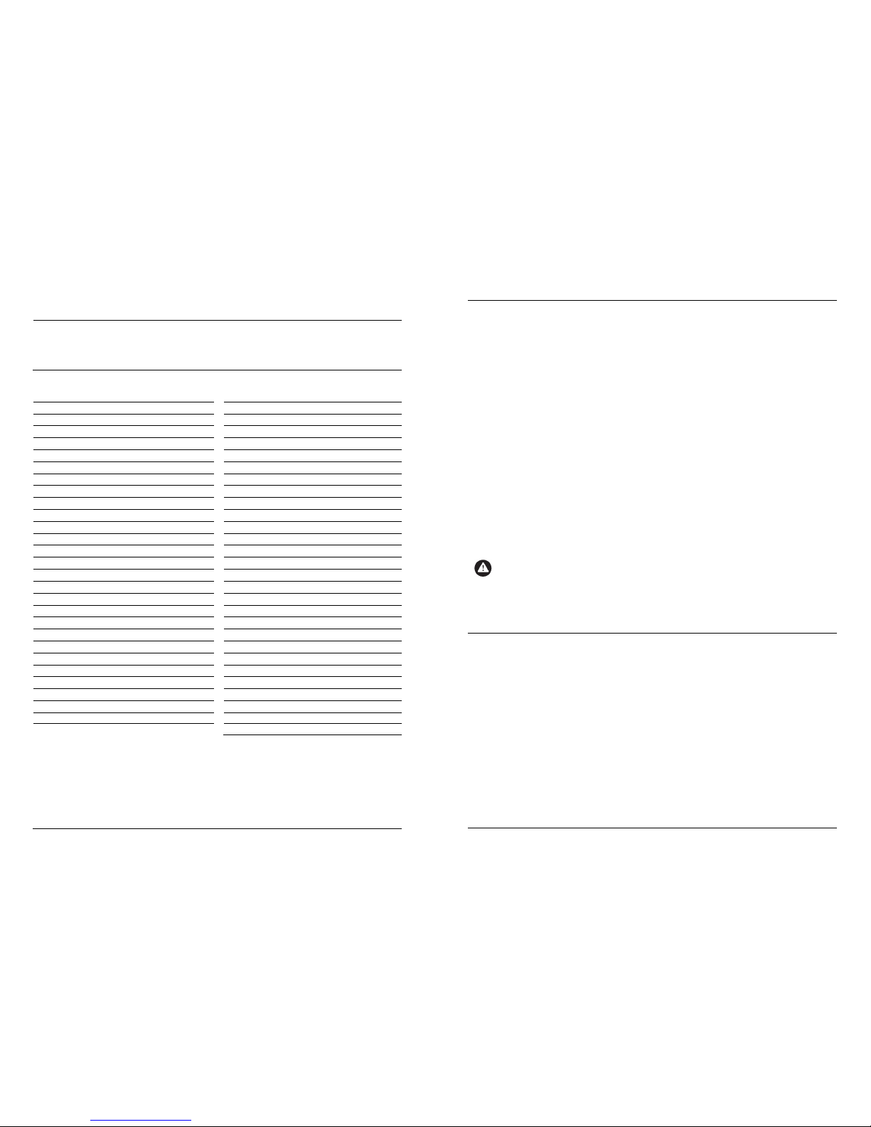
Contents
Section 1 – Important notes 3 Section 5 – Setting up 21
1.1 Intended use 3 5.1 Requirements for the building 21
1.2 Safety instructions 3 5.2 Requirements for ventilation system 2 1
Section 2 – Description of the device 4 5.3 Requirements for the technician 21
2.1 Purpose 4 5.4 Setting up procedure 21
2.2 Package contents 4 Section 6 – Control 22
2.3 Operating principle 4 6.1 Display and control panel on the unit 22
2.4 System design 5 6.2 Operating modes 23
2.5 Design 6 6.3 Installer menu 24
Section 3 – Technical data 7 6.3.1 Set Supply and Extract flow rates 24
3.1 Specifications 7 6.3.2 Change Settings 25
3.2 Characteristic curves 8 6.3.3 Load and Save and Reset Parameters 28
3.3 Dimension drawings 9 6.3.4 Diagnostics checks 28
Section 4 – Installation 10 6.3.5 Autocheck Routine 29
4.1 Requirements for the installation location 10 6.4 Operational functions 29
4.2 Installation of the unit 10 6.4.1 Bypass control 29
4.3 Condensate discharge line 11 6.4.2 Filter monitoring / filter message 3 0
4.4 Air-duct system 12 6.5 Internal safety functions 30
4.5 Electrical installation 13 6.5.1 Function for safe use with fire safety 30
4.5.1 Installation of Smoke Detector link wire 13 6.5.2 Frost protection of Heat exchanger 31
4.5.2 Connecting the unit to power supply 15 6.5.3 Safety cut-out 3 2
4.5.3 Electronics boards inside the unit 16 Section 7 – Fault Finding 32
4.5.4 Electrical circuit diagram 17 Section 8 – Map of the User menu 33
4.5.5 Installation humidity sensors (optional) 18 Section 9 – Map of the Installer menu 36
4.5.6 Installation PIR sensors (optional) 18 Section 10 – Settings Log table 37
4.5.7 Installation air-quality sensor (optional) 19 10.1 User Settings 37
4.5.8 Installation smoke detector (optional) 19 10.2 Installer Settings 38
4.5.9 Installation of duct heaters (optional)
20 Section 11 – Customer Service & Warranty 39
Section 12 - Environment and Disposal 39
2
Section
11 – Customer Service and Warranty
11 Guarantee
UK: This ventilation unit is guaranteed against defects for 2 years from date of purchase.
Xpelair reserve the right to repair or replace the unit.
Keep your purchase receipt.
Any problems, contact the address below.
Outside the UK: See International section.
In the unlikely event of a product breakdown during the guarantee period you should contact our Service and
Repair Helpline who will be able to assist with the repair and advise the best course of action to be taken.
Please DO NOT remove the product prior to making this call as this may invalidate your guarantee.
Technical advice and Service
Tel +44 (0) 844 372 7766
Fax: +44 (0) 844 372 7767
Email: service.request@redringxpelair.com
UK Sales Office and Spares
Tel: +44 (0) 844 372 7750
Fax: +44 (0) 844 372 7760
International
Guarantee – Contact your local distributor or Xpelair direct.
Technical advice and Service – Contact your local Xpelair distributor.
NOTE!
Please be prepared to tell us the exact device type an
d serial number S/N, for your ventilation unit so
that we can process your enquiry, customer service order or complaint correctly. You can find this
information on the rating plate located next to the display and control panel on the main cover of the
ventilation unit.
Section
12 –
Environment and Disposal
Be conscious about the environment and help to protect it.
Disposal of packaging
The ventilation unit has been packaged carefully to protect it from damage during transport. The transport
packaging consists of recyclable raw materials.
Please ensure to dispose of it in an environmentally responsible way.
Disposal of the device
Devices marked with this symbol must not be disposed of as normal residual waste. The device must be
collected separately including accessories, empty batteries and rechargeable batteries. The disposal must be
correct and in accordance with the applicable laws and regulations.
Redring Xpelair Group Limited
Newcombe House, Newcombe Way
Ort
on Southgate
Peterborough, Cambridgeshire
PE2 6SE, United Kingdom
Tel: +44 (0) 1733 456789
Fax: +44 (0) 1733 319610
Email: rxsalesoffice@redringxpelair.com
Internet: www.redringxpelair.com
© Xpelair Xpelair reserves the right to alter product specification or appearance without notice.
39
Section
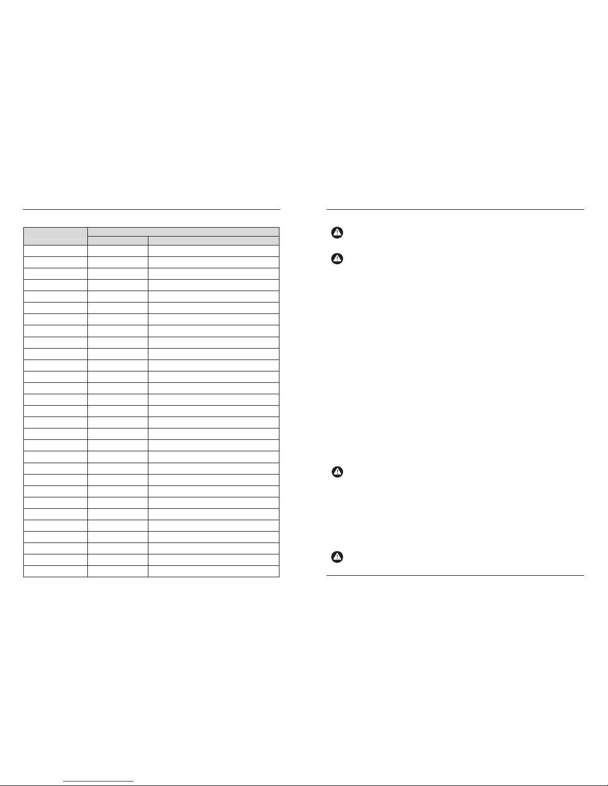
10 – Settings Log table
10.2 Installer Settings
Menu Title
Setting
Factory Default
New Value
Supply Speed 1 75 m3/hr
Supply Speed 2 115 m3/hr
Supply Speed 3 144 m3/hr
Extract Speed 1 75 m3/hr
Extract Speed 2 115 m3/hr
Extract Speed 3 144 m3/hr
Internal Humidistat
Ramp Trigger Sensitivity
4%
External Humidistat
Ramp Trigger Sensitivity
5%
CO2 Sensor Trigger
On / Off Levels
1200ppm / 1000ppm
AQS Sensor 1 Trigger
On / Off Levels
1200ppm / 1000ppm
AQS Sensor 2 Trigger
On / Off Levels
1200ppm / 1000ppm
Volt free Input 1 Enabled
Volt free Input 1
Action
Set to Speed 2
Volt free Input 2 Enabled
Volt free Input 2
Action
Set to Speed 1
Bypass feature On
Defrost heater Enabled
Defrost heater
Active months
October to May
Defrost Dependant
Sensor
Fresh Air
Defrost Switching
Temperature
3°C
Boost heater Enabled
Boost heater
Active months
October to May
Boost Dependant
Sensor
Boost Air
Boost Permitted
Temperature Drop
10°C
Flue in use increase
Supply Speed 1
10%
Flue in use increase
Supply Speed 2
10%
Flue in use decrease
Extract Speed 3
10%
Flue in use mode
Activation set by
On all the time
Room pressure
Fault Action by
Flue Detection Input 2
38
Section 1
– Important notes
In this user manual, especially important notes are marked as WARNING! or NOTE!
WARNING:
Warnings against hazards and errors that can cause severe or fatal injuries or can have serious
consequences for the product.
NOTE!
Useful notes and additional information.
This Installation Manual forms part of the ventilation unit and must be kept readily available at all times. For
the installer this manual must be used in conjunction with the User Manual. Both must be handed to any
technicians carrying out work on the unit and must be handed over to the new tenant when moving home.
1.1 Intended use
This ventilation unit is intended exclusively for the ventilation and exhaust ventilation of rooms within a
property. It must be installed in a frost-free interior room only.
Any other use and any use exceeding the design limits is not permitted. Any improper use can damage the
unit and can cause severe hazards.
The unit must not be altered or modified. The unit is guaranteed safe to use in accordance with these
instructions. The instructions in this Installation manual and in the corresponding User manual must be
observed.
1.2 Safety instructions
Failure to observe the safety instructions can cause hazards to the user as well as to the unit and will
invalidate the guarantee.
1.2.1 Installation
The ventilation unit must be installed by a qualified technician in accordance with this Installation manual.
The unit must be installed in a frost-free environment with good access and sufficient space for carrying out
any necessary maintenance or repair work. Two condensate hoses are required and must be correctly taken
to a drain in order to avoid any electrical hazards and any damage to the building. The unit must not be
installed where corrosive or inflammable gases can enter the unit, or where harmful pollutants can affect
people or put people at risk. All applicable fire regulations must be observed and complied with. Connecting
exhaust hoods to the ventilation unit is not permitted.
The unit must be installed by a qualified technician in compliance with all applicable standards and local
regulations, as well as in accordance with the Installation manual.
WARNING:
Before starting any work on the unit, the power supply
must be isolated in order to prevent any
electrical hazard.
Install and secure the mains cable through the cover cable gland. Ensure that the bare cable ends are correctly
and tightly secured into the mains supply terminal block.
Any setting up and programming must be carried out by a qualified technician in accordance with the
installation instructions.
1.2.2 Open Flue installations
Using the ventilation unit together with fuel burning devices (e.g. fire places, gas stoves) is subject to
special requirements.
WARNING:
It must be ensured that the unit is correctly set up so that no open flue gases are drawn back into
the room. All applicable national and regional guidelines and regulations must be observed.
3
Section 1
– Important notes
1.2.3 Start-up, use, interruption
The completed installation must be tested to ensure the unit works correctly. The user must read the User
manual in order to understand the procedures for use and maintenance.
WARNING:
The unit contains rotating fans. Do not put hands or fingers or any other objects into the unit or
ducting as this may cause injuries or damage to the unit.
1.2.4 Maintenance, repair, spare parts
In order to ensure continuous safe operation, the ventilation unit must be maintained regularly. Any
maintenance and repair work other than cleaning or changing filters must be carried out by a qualified
technician. Before opening the unit, turn off all associated circuits and secure against unintentional switchingon. Use only original spare parts from the manufacturer.
1.2.5 Alterations and modifications
Always consult a qualified technician if any alterations or modifications to the unit or system are required.
Structural changes to the building can also have an effect on the ventilation system: Always consult a qualified
technician.
Section
2 – Description of the Device
2.1 Purpose
The unit is designed for controlled supply and exhaust ventilation of frost-free rooms within a building.
The air flows through air ducts.
Connecting exhaust hoods to the ventilation system is not permitted. The unit is not to be used as a
dehumidifier.
2.2 Package contents
The unit is delivered with the following package contents:
• Ventilation unit with integrated control panel
• Condensate connection kit
• Installation manual and User manual
2.3 Operating principle
The unit is fitted with two fans using energy-saving “EC” technology which carries out a controlled air
exchange.
Used air is drawn in to the unit as Extracted air from the rooms with the highest air humidity and odour (e.g.
bathroom and kitchen) and is transferred to the outside as Exhaust air via a system of air ducts.
At the same time, a second duct system takes in Fresh air from outside the building and transfers it into living
rooms and bedrooms as Supply air.
Both air flows are completely separate and are passed through a heat exchanger which recovers the waste
heat from the extracted air to warm up the supply air. This ensures that the majority of heat energy is kept in
the building.
An internal bypass can be opened so that fresh air is supplied to the intake rooms without being warmed up
by the heat exchanger. Heat recovery is disabled in this case.
4
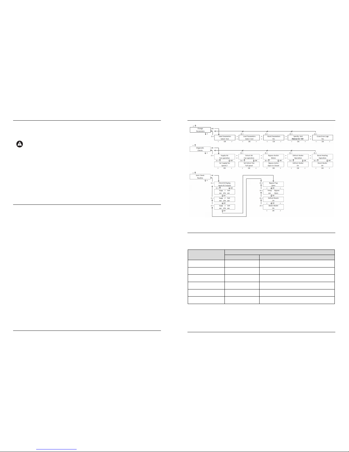
Section
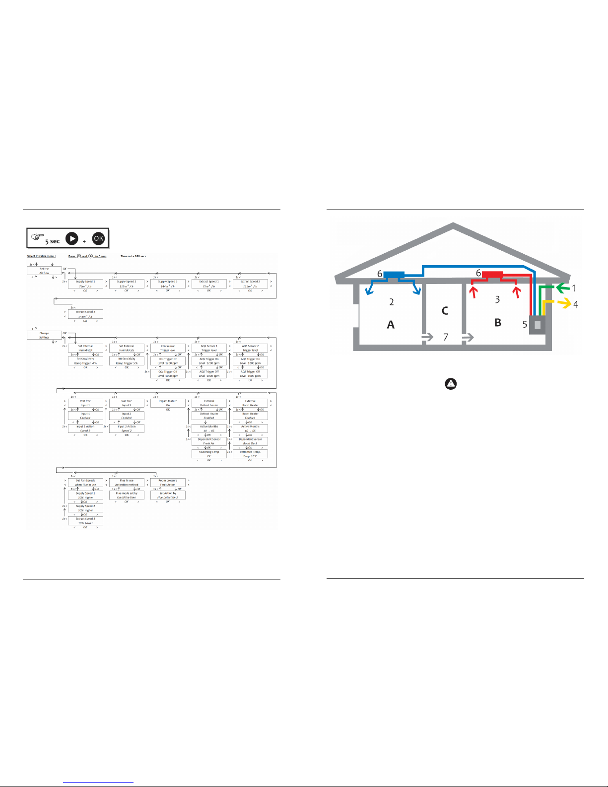
9 – Installer Menu
Fig. 9.1 Map of Installer Menu
Section
10 – Settings Log table
Use the table below to record the settings of the installed system.
10.1 User Settings
Menu Title
Setting
Factory Default
New Value
Set Speed 3
Boost Timer
30 minutes
Program Timers Off
Filter
Change Time
6 months
Setup Summer
Bypass
On
Bypass Period April to October
Bypass Switching
Temperature
21°C
37
Section
9 – Installer Menu
9 Map of the Installer menu
Installer menu continued on next page.
36
Section
2 – Description of the Device
Fig. 2.1 Supply-air/extract-air system with heat recovery
1 Fresh air* 6 Air diffuser NOTE!
* Outside installation points for the Fresh Air intake
(1) and the Exhaust Air outlet (4) MUST be
sufficiently far enough apart to prevent the exhaust
air being drawn into the property through the Fresh
air duct. (No “re-circulation”).
2 Supply air 7 Air transfer opening
3 Extract air A Supply-air area
4 Exhaust air* B Extract-air area
5 Ventilation unit C Air transfer area
Halls and corridors normally act as transfer areas in which the air from the supply areas flows into the extract
areas. Undercut doors and air transfer grilles are used so that the air flow between rooms is not restricted.
Where fitted, a radial air-duct system with direct pipe routes between air diffusers and supply air/extract air
valves:
• Simplifies the balancing of volume flow rates and pressures
• Prevents sound transmitting from adjacent rooms
• Makes cleaning easier, due to direct pipe routes
2.4 System Design
The ventilation system must be properly designed by a qualified ventilation engineer so that it meets the
requirements of the building.
The plan will determine :
• The location of the Supply air inlets (Low pollution: Usually living rooms, bedrooms, recreation rooms,
offices, etc)
• The location of the Extract air outlets (Higher pollution: Usually bathrooms, toilets, kitchens, utility rooms,
etc)
• The requirement for any undercut doors and air transfer grilles. (Usually Halls and corridors, etc)
• The overall required Supply flow rate
• The overall required Extract flow rate
• Supply and Extract flow rates into individual rooms
5
Please note: diagram for explanation purposes only. Not actual spigot layout
Section
2 – Description of the Device
(Devices such as grilles or diffuser or dampers can be used to set individual room rates)
NOTE!
See Table 3.1 on Page 7 for Factory set Supply and Extract flow rates.
See Section 6.3 Installer menu – Set the Air flow for any flow rates need to be changed. (As
determined by the design).
NOTE!
The following documents are needed for correct designin
g of the system:
• Details of the building and the rooms or areas to be ventilated.
• Floor plans indicating room use.
• Sectional drawing indicating room heights.
NOTE!
An incorrectly specified system can lead to insufficient ventilation and can cause high noise levels
and an excessive energy consumption.
Any applicable guidelines and regulations must be observed and complied with.
WARNING:
Using the ventilation unit together with open flue fuel burning devices (e.g. fireplaces, gas stoves) is
subject to further special requirements.
Any applicable national as well as regional guidelines and regulations must be observed.
We strongly recommend you consult a qualified specialist.
WARNING:
Applicable fire regulations must be complied with. For example, fire dampers should be fitted,
where required.
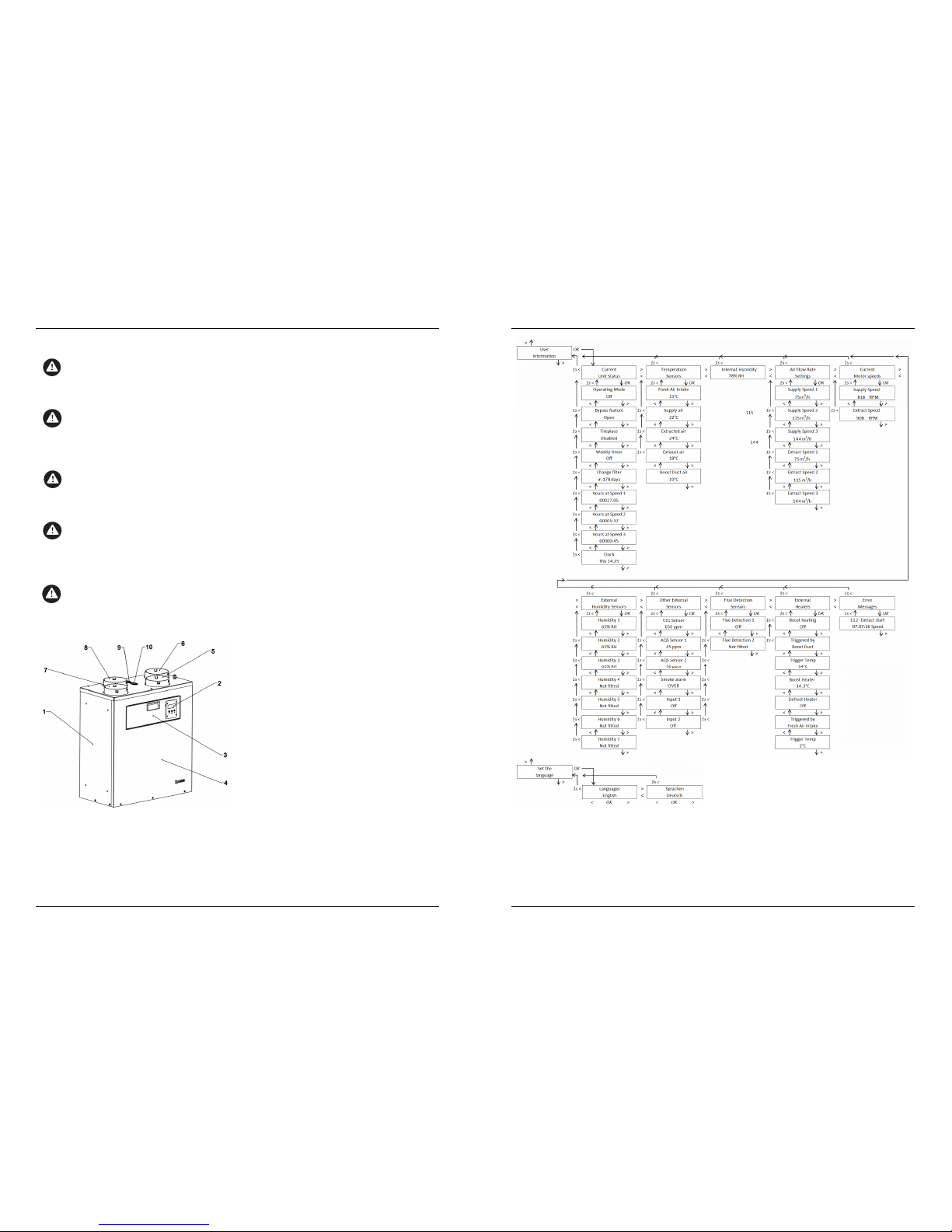
2.5 Design
1 Back plate and sides
2 Control panel and display
3 Inspection door
4 Front cover
5 Connection nozzle, extract air
6 Connection nozzle, supply air
7 Connection nozzle, exhaust air
8 Connection nozzle, fresh air
9 Defrost Heater supply output
(Natural Air 180 PH variant only) *
10 Boost Heater supply output
(Natural Air 180 PH variant only) *
* External Heater boxes (not supplied) are available
as an accessory. (See User Manual for details).
Fig. 2.2 Structure of the ventilation unit
6
Section
8 – User Menu
Fig. 8.1 Map of User Menu
35
 Loading...