

Page 1
SB-HF950P
Colour
(K)... Black Type
ORDER NO. MD0702010CE
A6
Speaker System
Specification
Type 2 way, 2 speaker system (Bass reflex)
Speaker unit(s) Impedance 6 Ω
Full range 6.5 cm (2-1/2”) cone type
Full range 6.5 cm (2-1/2”) cone type
Input power (IEC) 250 W* (Max)
Output sound pressure 83 dB/W (1.0 m)
Cross over frequency 5kHz
Frequency range 79 Hz - 25 kHz (-16 dB)
95 Hz - 22 kHz (-10 dB)
Dimensions (W x H x D) 252 x 1123 x 235 mm
Mass 3.8kg(8.4lbs)
Notes :
1. Specifications are subject to change without notice.
Mass and dimensions are approximate.
2. Total harmonic distortion is measured by the digital spectrum
analyzer.
* : Rating with low-cut filter equipped amplifier.
(9-29/32” x 44-7/32” x 9-1/4”)
CONTENTS
Page Page
1 System Combination
1.1. System Breakdown
2 Assembling and Disassembling
2.1. Disassembly flow chart
3
3
4
4
2.2. Disassembly of Upper box assembly
2.3. Disassembly of Upper rear cabinet
2.4. Disassembly of Woofer 1
5
5
6
© 2007 Matsushita Electric Industrial Co. Ltd.. All
rights reserved. Unauthorized copying and
distribution is a violation of law.
Page 2

SB-HF950P
2.5. Disassembly of Woofer 2 6
2.6. Disassembly of Terminal jack
2.7. Disassembly of Lower box assembly
2.8. Disassembly of Lower rear cabinet assembly
2.9. Disassembly of Base stand assembly
2.10. Assembly of Front Speakers
10
3 Connection of the Speaker Cables
7
4 Connection of the Wiring Diagram
5 Exploded view
8
9
9
5.1. Cabinet Parts Location
5.2. Packaging
6 Replacement Parts List
11
14
15
15
16
17
2
Page 3
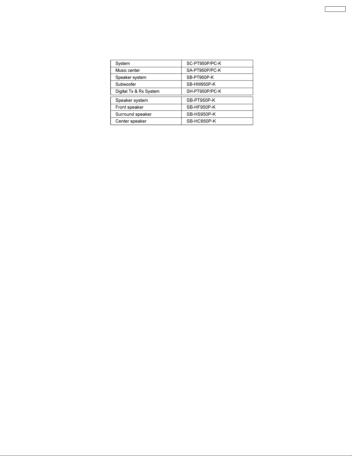
1 System Combination
1.1. System Breakdown
Note :
The diagrams below show the breakdown for speaker combinations used in main unit systems.
SB-PT950P-K consists of SB-HF950P-K (x2), SB-HS950P-K (x2), SB-HC950P-K (x1)
SB-HF950P
3
Page 4
SB-HF950P
2 Assembling and Disassembling
“ATTENTION SERVICER”
Some chassis components may have sharp edges. Be carefu l when disassembling and servicing.
1. This section describes procedures for checking the operation of the major printed circuit boards and replacing the main
components.
2. For reassembly after operation checks or replacement, reverse the respective procedures.
Special reassembly procedures are described only when required.
3. Select items from the following index when checks or replacement are required.
4. Refer to the Parts No. on the page of “Parts Location and Replacement Parts List” (Section 6), if necessary.
Below is the list of disassembly sections
· Disasse mbly of Upper box assembly
· Disasse mbly of Upper rear cabinet
· Disasse mbly of Woofer 1
· Disasse mbly of Woofer 2
· Disasse mbly of Terminal jack
· Disasse mbly of Lower box assembly
· Disasse mbly of Lower rear cabinet assembly
· Disasse mbly of Lower base stand assembly
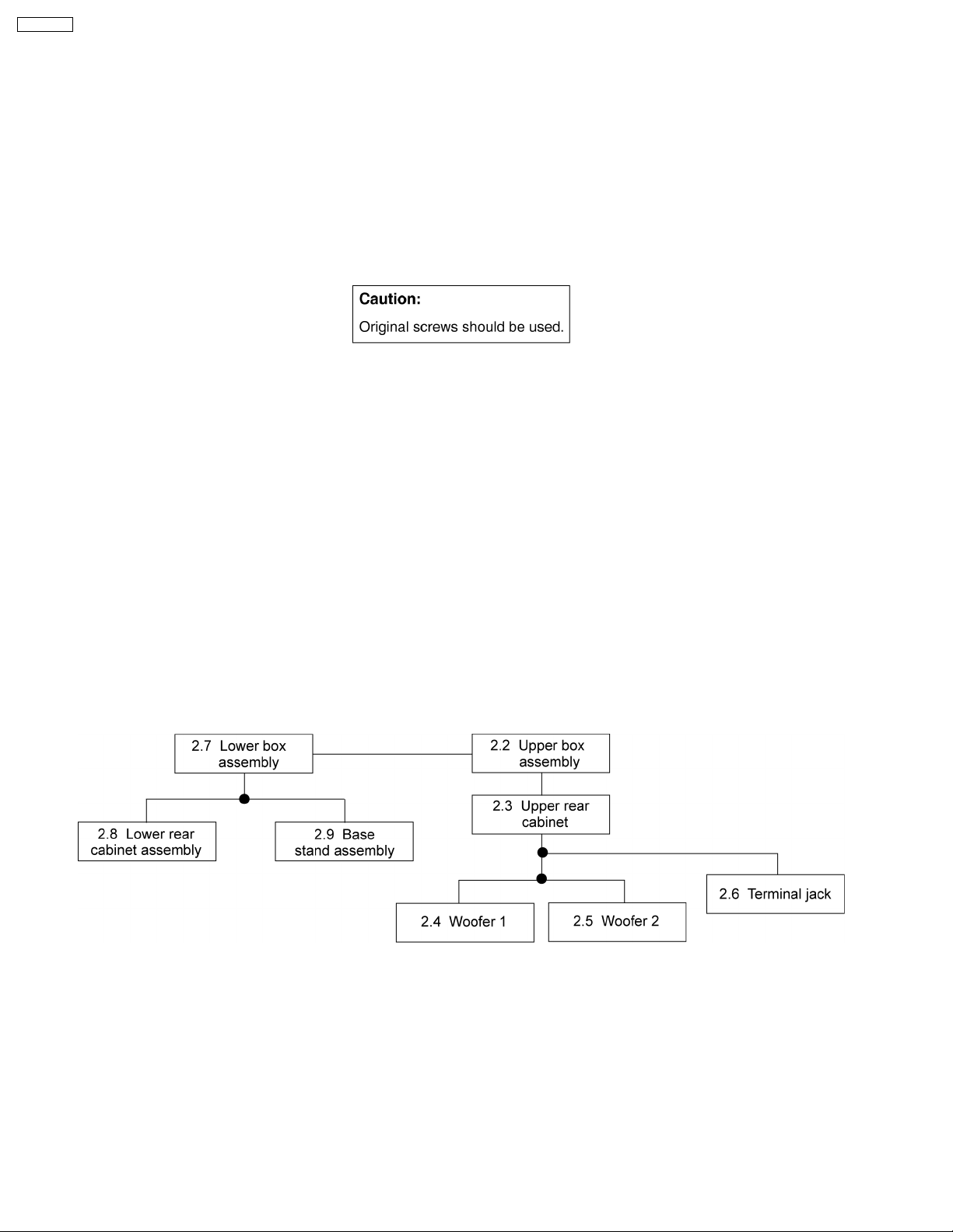
2.1. Disassembly flow chart
The following chart is the procedure for disassembling the casing and inside parts for internal inspection when carrying out the
servicing.
To assemble the unit, reverse the steps shown in the chart as below.
4
Page 5
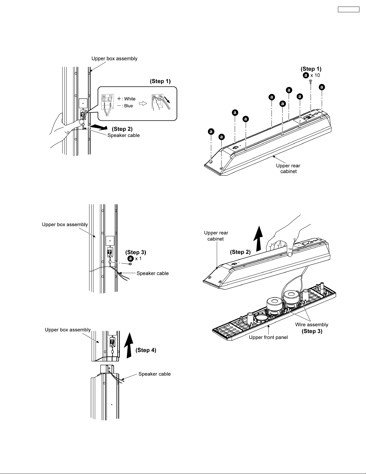
2.2. Disassembly of Upper box
assembly
Step 1: Remove the white (+) and blue (-) wires.
Step 2: Pull out the speaker cable from the groove.
SB-HF950P
2.3. Disassembly of Upper rear
cabinet
Follow (step 1) to (step 4) in item 2.2.
Step 3: Remove 1 screw.
Step 1: Remove 10 screws.
Step 2: Lift up the upper rear cabine t as arrow shown.
Step 3: Detach wire assembly to remove it.
Step 4: Remove the upper box assembly unit as arrow shown.
5
Page 6
SB-HF950P
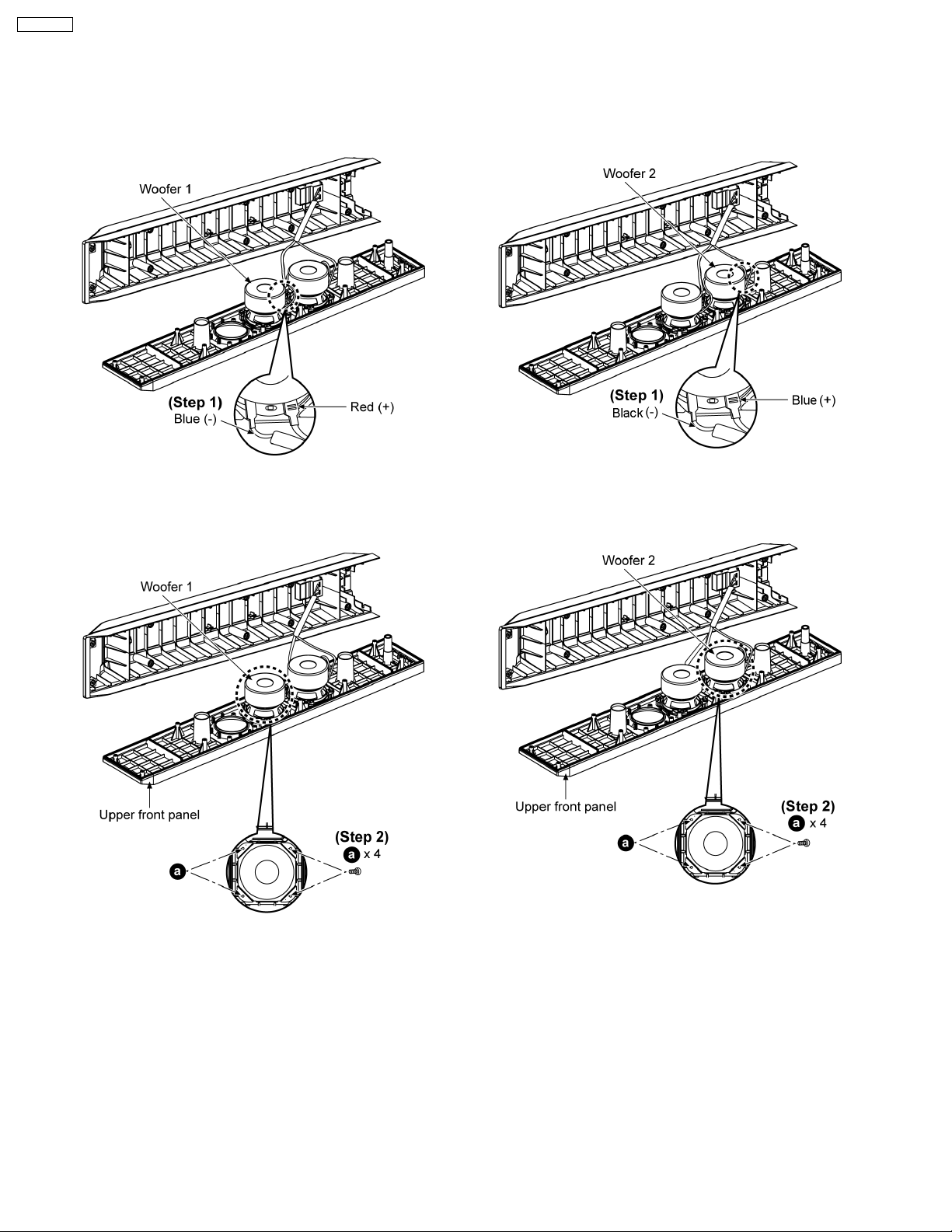
2.4. Disassembly of Woofer 1
2.5. Disassembly of Woofer 2
Follow (step 1) to (step 4) in item 2.2.
Follow (step 1) to (step 2) in item 2.3.
Step 1: Detach the blue (-) and red (+) wires.
Follow (step 1) to (step 4) in item 2.2.
Follow (step 1) to (step 2) in item 2.3.
Step 1: Detach the black (-) and blue (+) wires.
Step 2: Remove 4 screws.
Step 2: Remove 4 screws.
6
Page 7

2.6. Disassembly of Terminal jack
Follow (step 1) to (step 4) in item 2.2.
Follow (step 1) to (step 2) in item 2.3.
SB-HF950P
Step 1: Detach the black (-) and red (+) wires.
Step 3: Remove terminal jack as arrow shown.
Step 2: Remove 1 screw from the terminal jack.
7
Page 8

SB-HF950P
2.7. Disassembly of Lower box
assembly
Follow (step 1) to (step 4) in item 2.2.
Step 1: Pull out the speaker cable from the ridges.
Step 2: Pull out the speaker cable from the groove inside by
using hand.
Step 6: Remove the lower box assembly as arrow shown.
Step 7: Pull out the speaker cable.
Step 3: Remove 1 screw.
Step 4: Remove 2 screws.
Step 5: Pull out the speaker cable from the groove as arrow
shown.
8
Page 9

2.8. Disassembly of Lower rear
cabinet assembly
SB-HF950P
2.9. Disassembly of Base stand
assembly
Follow (step 1) to (step 4) in item 2.2.
Follow (step 1) to (step 7) in item 2.7.
Follow (step 1) to (step 4) in item 2.2.
Follow (step 1) to (step 6) in item 2.7.
Step 1: Remove 4 screws.
Step 1: Remove 4 screws.
Step 2: Remove the lower rear cabinet assembly.
9
Page 10

SB-HF950P
2.10. Assembly of Front Speakers
10
Page 11

SB-HF950P
3 Connection of the Speaker Cables
· Be sure to connect speaker cables before connecting the AC power supply cord.
· The load impedance of any speaker used with this unit must be 6 Ω.
· Be sure to connect the cable from the right speaker to the right terminal and the cable from the left speaker to the left terminal.
1. Twist and pull off the vinyl tip of the speaker cords. If the speake r cords do not have vinyl tips, connect them directly to the
terminals. Make sure the bare ends of the wires are not unravelled.
2. Insert the wire to the rear panel of the unit and close the lever.
Notes :
· To prevent damage to circuitry, never short-circuit positive (+) and negative (-) speaker wires.
· Be sure to connect only positive (white) wires to positive (+) terminals and negative (blue) wires to negative (-) terminals.
11
Page 12

SB-HF950P
Positioning the speakers
12
Page 13

Note on speaker use
· Use only supplied speakers.
Using other speakers can damage the unit, and sound quality will be negatively affecte d.
· You can damage your speakers and shorten their useful life if you play sound at high levels over extended periods.
· Reduce the volume in the following cases to avoid damage.
−
− When playing distorted sound.
− −
−
− When the speakers are reverberating due to a record player, noise from FM broadcasts, or continuous signals from an
− −
oscillator, test disc, or electronic instrument.
−
− When adjusting the sound quality.
− −
−
− When turning the unit on or off.
− −
If irregular coloring occurs on your television
The front and center speakers are designed to be used close to a television, but the picture may be affected with some
televisions and setup combinations.
If this occurs, turn the television off for about 30 minutes.
The demagnetizin g function of the television should correct the problem.
If it persists, move the speakers further away from the television.
SB-HF950P
Caution
Do not touch the front netted area of the speakers. Hold by the sides.
e.g. Center speaker
Do not stand on the base. Be cautious when children are near..
e.g. Front speaker
13
Page 14

SB-HF950P
4 Connection of the Wiring Diagram
14
Page 15

5 Exploded view
5.1. Cabinet Parts Location
SB-HF950P
15
Page 16

SB-HF950P
5.2. Packaging
The diagram below shows the packaging for speakers in SB-PT950P-K.
16
Page 17
6 Replacement Parts List
Notes :
· Important safety notice :
When replacing any of these components, be sure to use
only manufacturer’s specifi ed parts shown in the parts list.
· [M] markings in the Remarks column s indicates parts
supplied by PAVCSG.
Ref.
No.
1 RYPX0192-K U/FRONT CABINET ASSY [M]
2 RYKX0356-K U/REAR CABINET ASS’Y [M]
3 RYPX0203-K LOWER BOX ASS’Y [M]
3-1 REEX0449J-2K SPEAKER CORD (L/BOX) [M]
3-2 XTB3+10GFJ SCREW [M]
4 XSN5+12FJ SCREW [M]
5 RYPX0206-K BASE COVER ASS’Y [M]
5-1 RKAX0033-K LEG RUBBER (BASE) [M]
5-2 RGPX0314-K BASE COVER [M]
6 K4BC02B00017 TERMINAL [M]
7 REEX0721 TRANSIT WIRE [M]
8 RGKX0417-S ORNAMENT BADGE [M]
9 RGNX0444-K1 SPEC LABEL [M]
10 XTB3+10GFJ SCREW [M]
Part No. Part Name & Description Remarks
CABINET AND CHASSIS
SB-HF950P
ACCESSORIES
A1 REEX0449E-2K SPEAKER CORD [M]
PACKING MATERIALS
P1 RPNX0457 POLYFOAM [M]
P2 RPFX0209 MIRAMAT BAG (HF) [M]
P3 RPFX0212 MIRAMAT BAG (BASE) [M]
P4 RPFX0210 MIRAMAT BAG (HC) [M]
P5 RPFX0211 MIRAMAT BAG (HS) [M]
SPEAKER
SP1 EAS65P122B WOOFER [M]
17
FLE0702W/S /D
 Loading...