

Page 1

Specifications
Type 3 way, 3 speaker system (Bass reflex)
Speaker(s)
Woofer 16 cm cone type
Tweeter 6 cm cone type
Super tweeter Piezo type
Impedance
HIGH 3 Ω
LOW 3 Ω
Input power (IEC)
HIGH 110 W (Max)
LOW 110 W (Max)
Output sound pressure level 88 dB/W (1.0 m)
Cross over frequency 1.5kHz,10kHz
ORDER NO. MD0703024CE
Speaker System
SB-AK750PL
Colour
(K)...Black Type
Frequency range 35 Hz to 24 kHz (-16 dB)
41 Hz to 27 kHz (-10 dB)
Dimensions (W X H X D) 232 X 373 X 226 mm
Mass 3.4 kg
Notes:
1. Specifications are subject to change without notice. Mass and
dimensions are approximate.
2. Total harmonic distortion is measured by the digital spectrum
analyzer.
3. The labels “HIGH“ and “LOW” on the rear of the speakers refer to
High frequency and Low frequency.
CONTENTS
Page Page
1 System Combination 2
1.1. System Breakdown
2 Assembling and Disassembling
2.1. Caution
2.2. Disassembly Procedures
2.3. Disassembly Flow Chart
2.4. Disassembly of Rear cabinet assembly
2.5. Disassembly of Woofer
2
3
3
3
3
4
5
2.6. Disassembly of Tweeter
2.7. Disassembly of Piezo
3 Connection of the Speaker Cables
4 Connection of the Wiring Diagram
5 Exploded Views
5.1. Cabinet Parts Location
5.2. Packaging
6 Replacement Parts List
© 2007 Matsushita Electric Industrial Co. Ltd.. All
rights reserved. Unauthorized copying and
distribution is a violation of law.
10
11
5
6
7
8
9
9
Page 2

SB-AK750PL
1 System Combination
1.1. System Breakdown
Note:
The table below show the breakdown for speaker combinations used in main unit system.
System SC-AK750PL-K
Music Center SA-AK750PL-K
Front Speakers SB-AK750PL-K
Subwoofer SB-WAK750PL-K
System SC-AK750GCP-K
Music Center SA-AK750GCP-K
Front Speakers SB-AK750PL-K
Subwoofer SB-WAK750PL-K
2
Page 3
2 Assembling and Disassembling
2.1. Caution
“Attention Servicer”
Some chassis components may have sharp edges.
Be careful when disassembly and servicing.
1. This section describes procedure for checking the operation of replacing the main components.
2. For reassembly after operation checks or replacement, reverse the respective procedures.
3. Select items from the following index when checks or replacement are required.
4. Refer to the Part No.on the page of “Parts Location and Replacement Parts List” (Section 6) if necessary.
SB-AK750PL
2.2. Disassembly Procedures
· Disassembly of Rear cabine t assembly
· Disassembly of Woofer
· Disassembly of Tweeter
· Disassembly of Piezo
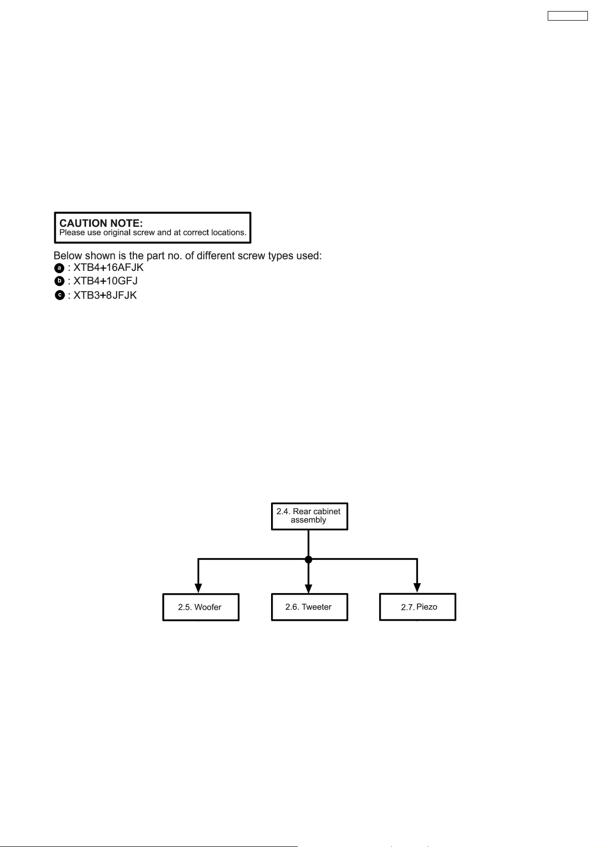
2.3. Disassembly Flow Chart
The following chart is the procedure for disassembly the casing and inside parts for internal inspection when carrying out the
servicing.
To assemble the unit, reverse the steps shown in the chart as below.
3
Page 4

SB-AK750PL
2.4. Disassembly of Rear cabinet
assembly
Step 3: Detach the front panel as arrow shown.
Step 1: Remove 4 screws from front panel.
Step 2: Insert flathead screwdriver into the grooves to push the
front panel as arrow shown.
Step 4: Detach the (+) red and (-) black wires from woofer.
4
Page 5

2.6. Disassembly of Tweeter
Follow the (step 1) to (step 3) in item 2.4.
Follow the (step 5) in item 2.4.
SB-AK750PL
Step 5: Detach the (+) gray and (-) blue wires from tweeter.
Step 6: Remove the rear cabinet assembly.
2.5. Disassembly of Woofer
Follow the (step 1) to (step 4) in item 2.4.
Step 1: Detach the (+) red and (-) black wires from tweeter.
Step 1: Remove 4 screws from woofer.
Step 2: Remove the woofer.
Step 2: Remove 4 screws from tweeter.
Step 3: Remove the tweeter.
5
Page 6

SB-AK750PL
2.7. Disassembly of Piezo
Follow the (step 1) to (step 3) in item 2.4.
Follow the (step 1) in item 2.6.
Step 1: Remove the glue from piezo.
Step 2: Remove the piezo.
For assembly of piezo, follow the steps below:
1. Clear up areas on the piezo.
2. Apply glue to piezo and paste to the front panel.
6
Page 7

3 Connection of the Speaker Cables
SB-AK750PL
· Be sure to connect speaker cables before connecting the
AC power supply cord.
· The load impedance of any speaker used with this unit must
be 3 Ω.
· Be sure to connect the cable from the right speaker to the
right terminal and the cable from the left speake r to the left
terminal.
Placement
Speakers are designed identically so that no left or right
channel orientation is necessary.
Connection
Use only the supplied speakers
The combination of the main unit and speakers provide the
best sound. Using other speakers can damage the unit and
sound quality will be negatively affecte d.
Notes:
· Keep your speakers at least 10mm away from the system
for proper ventilation.
· These speakers do not have magnetic shielding. Do not
place them near televisions, personal computers or other
devices easily influenced by magnetism.
· You can damage your speakers and shorten their useful life
if you play sound at high levels over extended periods.
· Reduce the volume in the following cases to avoid damage.
−
− When playing distorted sound.
− −
−
− When adjusting the sound quality.
− −
7
Page 8

SB-AK750PL
4 Connection of the Wiring Diagram
8
Page 9

5 Exploded Views
5.1. Cabinet Parts Location
SB-AK750PL
9
Page 10

SB-AK750PL
5.2. Packaging
10
Page 11

6 Replacement Parts List
Notes:
· Important safety notice:
When replacing any of these components, be sure to use
only manufacturer’s specified parts shown in the parts list.
· [M] markings in the Remarks column s indicates parts
supplied by PAVCSG.
Ref. No. Part No. Part Name & Description Remarks
CABINET AND CHASSIS
1 RYKV0088-K REAR CABINET ASS’Y [M]
2 RYPV0193-K FRONT PANEL ASS’Y [M]
3 REEV0174 WIRE ASS’Y (PIEZO) [M]
4 RGNV0309 SPEC LABEL [M]
5 RKA0072-KJ LEG CUSHION [M]
6 XTB3+8JFJK SCREW [M]
7 XTB4+10GFJ SCREW [M]
8 XTB4+16AFJK SCREW [M]
PACKING MATERIALS
P1 RPNV0134 POLYFOAM [M]
P2 RPFX0183 MIRAMAT BAG [M]
SB-AK750PL
SPEAKER
SP1 EAS16PL751A WOOFER [M]
SP2 L0AA06A00037 TWEETER [M]
11
PROB0703
 Loading...