

Page 1

User Guide
For Xerox SAFEStor
Storage Enclosure
Revision 1 .0
J anuary 200 6
Page 2

Page ii
Table of Contents
Chapter 1 – Introduction............................................................................................................................... 1
Featu res and B enefits
................................................................................................................................1
Configurations ..........................................................................................................................................1
Understanding RAID
...................................................................................................................................... 2
RAID 0.................................................................................................................................................2
RAID 1.................................................................................................................................................2
RAID 0+1.............................................................................................................................................3
RAID 3.................................................................................................................................................3
RAID 5.................................................................................................................................................4
RAID 6.................................................................................................................................................4
Chapter 2 – Initial Setup and Installation......................................................................................................5
Safety Statem en ts
...................................................................................................................................... 5
U n p acking
.................................................................................................................................................5
Enviro n m ental C o n siderations
.................................................................................................................. 5
Temperature .........................................................................................................................................5
Air Flow...............................................................................................................................................6
Electri c al C onsid eratio ns
......................................................................................................................6
Installing a D isk D rive
..............................................................................................................................6
Locating Co m ponents
................................................................................................................................6
Front View of XRX-2PSQX-651U4, XRX-2PSQX-652-FC...............................................................6
Rear View of the unit ........................................................................................................................... 7
FRU replacement ................................................................................................................................. 7
Cooling Fan.....................................................................................................................................7
RAID Controller..............................................................................................................................8
Drive Carrier ...................................................................................................................................9
Chapter 3 – Initial Configuration................................................................................................................11
Attaching the SCSI Cables to XRX-2PSQX-651-U4..............................................................................11
A ttaching the Fibre C han n el C ables to
XRX-2PSQX-652-FC ................................................................11
A c cessing the RA ID C o n troller
............................................................................................................... 11
V T 10 0 term inal (via serial p o rt)
.........................................................................................................11
RAID subsystem RS-232C Port Configuration ..................................................................................11
W eb bro w ser - based R A ID m anag er
...................................................................................................12
W eb bro w ser - based R A ID m anag er via H T T P Pro x y
........................................................................13
Configuration Menu Tree...................................................................................................................14
Front Panel Operation ........................................................................................................................14
Chapter 4 – Configuration Using Web Module...........................................................................................16
Initial C on figuration
................................................................................................................................16
Q u ick F u n ctions
.................................................................................................................................16
R A ID S et F un ctions
...........................................................................................................................17
Create a RAID Set...................................................................................................................... 17
Delete RAID Set............................................................................................................................18
Expand RAID Set.......................................................................................................................... 19
Activate RAID Set......................................................................................................................... 19
Create Hot Spare ...........................................................................................................................20
Delete Hot Spare ...........................................................................................................................20
Rescue RAID Set........................................................................................................................... 21
V o lu m e S et F u n ctions
........................................................................................................................22
Create a Volume Set......................................................................................................................22
Delete Volume Set......................................................................................................................... 24
Modify Volume Set.......................................................................................................................24
Check Volume Set.........................................................................................................................25
Stop Volume Set Check.................................................................................................................26
Physical Drives
.................................................................................................................................26
Create Pass Through......................................................................................................................26
Modify Pass Through ....................................................................................................................27
Page 3

Page iii
Delete Pass Through......................................................................................................................28
Identify Drive ................................................................................................................................29
Syste m C ontrols
.................................................................................................................................30
System Configuration....................................................................................................................30
U320 SCSI Target Configuration..................................................................................................31
EtherNet Config ............................................................................................................................31
Alert By Mail Configuration .........................................................................................................32
SNMP Configuration.....................................................................................................................34
NTP Configuration........................................................................................................................35
Generate Test Event ......................................................................................................................36
Clear Event Buffer......................................................................................................................... 36
Modify Password...........................................................................................................................36
Upgrade Firmware.........................................................................................................................37
Restart Controller ..........................................................................................................................37
Info rm atio n
......................................................................................................................................... 38
RAID Set Hierarchy ......................................................................................................................38
System Information .......................................................................................................................39
Hardware Monitor ......................................................................................................................... 39
Chapter 5 – Configuration Using VT100.....................................................................................................41
K eyboard N av ig atio n
..............................................................................................................................41
Login
.......................................................................................................................................................41
M ain M en u
..............................................................................................................................................41
Q u ick V olum e/R aid S etu p
.................................................................................................................. 42
RAID Level:..................................................................................................................................42
Select Capacity:............................................................................................................................. 42
Stripe size......................................................................................................................................42
R aid S et Fu n ction
...............................................................................................................................43
Create Raid Set.............................................................................................................................. 43
Delete Raid Set.............................................................................................................................. 44
Expand Raid Set............................................................................................................................44
Activate Incomplete Raid Set........................................................................................................45
Create Hot Spare ...........................................................................................................................45
Delete Hot Spare ...........................................................................................................................46
Raid Set Information ..................................................................................................................... 46
V o lu m e S et F u n ction
..........................................................................................................................47
Create Volume Set......................................................................................................................... 47
Delete Volume Set......................................................................................................................... 50
Modify Volume Set.......................................................................................................................50
Check Volume Set.........................................................................................................................52
Stop Volume Set Check.................................................................................................................52
Display Volume Set Info............................................................................................................... 52
Physical Drive.................................................................................................................................... 52
View Drive Information ................................................................................................................53
Create Pass-Through Disk.............................................................................................................53
Modify Pass-Through Disk ........................................................................................................54
Delete Pass-Through Disk.............................................................................................................55
Identify Selected Drive..................................................................................................................55
R A ID System Functio n
......................................................................................................................56
Mute The Alert Beeper................................................................................................................56
Alert Beeper Setting ......................................................................................................................57
Change Password ..........................................................................................................................57
RAID/JBOD Function..................................................................................................................58
Background Task Priority..............................................................................................................58
Maximum SATA Mode.................................................................................................................59
HDD Read Ahead Cache...............................................................................................................59
Stagger Power On..........................................................................................................................60
HDD SMART Status Polling ........................................................................................................ 60
Capacity Truncation ...................................................................................................................... 61
Page 4

Page iv
Terminal Port Config. ................................................................................................................. 61
Update Firmware........................................................................................................................... 62
Restart Controller ..........................................................................................................................63
U 3 2 0 S CSI T arget C o n fig
.................................................................................................................. 63
Ethernet C o n figuration
.......................................................................................................................64
DHCP Function.............................................................................................................................64
Local IP address ............................................................................................................................64
Http Port Number..........................................................................................................................65
Telnet Port Number.......................................................................................................................65
Ethernet Address ...........................................................................................................................65
V ie w System Events
...........................................................................................................................65
Clear E v ents B u ffer
............................................................................................................................65
Hardware Monitor
............................................................................................................................66
Syste m Inform ation
............................................................................................................................67
Page 5

Page v
Preface
This User Guide describes the installation, configuration and operation of the following
Xerox storage products:
•
XRX-2PSQX-651-U4
•
XRX-2PSQX-652-FC
Audience
This User Guide is intended for use by the person installing and/or operating the Xerox
XRX series storage enclosure. For details about the host system, refer to the documentation
supplied with the host system
Conventions Used In This User Guide
The following conventions are used throughout this User Guide.
A WARNING means beware. There is a risk of electric shock or personal injury.
Before working on the enclosure, be aware of the hazards that exist.
A CAUTION means take care. There is a risk of causing damage to the
equipment or of losing data.
A NOTE gives general information, such as helpful tips and references to
related information.
Page 6

SAFEStor User Guide
Page 1
Chapter 1 – Introduction
Thank you for purchasing your Xerox SAFEStor RAID System. Designed for speed, reliability,
compatibility and performance. The RAID System is easy to install, providing an outstanding
and versatile solution to meet all your data storage requirements. The unit is available with either
Ultra-320 parallel SCSI or 4 gigabit Fibre Channel Host Interfaces utilizing Serial ATA (SATA)
disk technology.
This User Guide presumes that you are familiar with standard computer operations including
managing and organizing files and folders. If you are unfamiliar with these operations, please
consult your computers User Guide.
F eatures and Benefits
The Xerox SAFEStor RAID Series offers an extremely versatile and low cost solution, perfect
for any End-User environment where high performance, problem free mass storage is required,
including:
•
Back-up storage.
•
Direct Attached Storage – High-speed local storage device for dedicated workstations.
•
Server Attached Storage – High-speed storage device attached to your server.
Configurations
The Xerox SAFEStor RAID Array is available in two capacity point configurations:
U320 SCSI models have the following part numbers:
XRX-2PSQX-651-U4-3: SAFEStor RAID, Three 250GB drives, RAID 5 formatted
capacity: 500GB
XRX-2PSQX-651-U4-6: SAFEStor RAID, Six 250GB drives, five in RAID set, RAID 5
formatted capacity: 1TB, One HOT spare
Fibre Channel models have the following part numbers:
XRX-2PSQX-651-U4-3: SAFEStor RAID, Three 250GB drives, RAID 5 formatted
capacity: 500GB
XRX-2PSQX-651-U4-6: SAFEStor RAID, Six 250GB drives, five in RAID set, RAID 5
formatted capacity: 1TB, One HOT spare
In addition SCSI models can be configured with tape libraries, the corresponding part numbers
are:
XRX-2PSQX-651-U4-3-VXA SAFEStor RAID, three 250GB drives, 500GB
formatted capacity, with VXA tape library
XRX-2PSQX-651-U4-6-VXA SAFEStor RAID, six 250GB drives, 1TB formatted
capacity , one HOT spare drive, with VXA tape library
Page 7

SAFEStor User Guide
Page 2
Understanding RAID
RAID is an acronym for Redundant Array of Independent Disks. A RAID system consists of an
array of multiple independent hard disk drives that provide high performance and fault tolerance.
The RAID controller implements several levels of the Berkeley RAID technology. An
appropriate RAID level is selected when the volume sets are defined or created. This decision is
based on disk capacity, data availability (fault tolerance or redundancy) and disk performance.
The RAID controller makes the RAID implementation and the disks physical configuration
transparent to the host operating system. This means that the host operating system drivers and
software utilities are not affected, regardless of the RAID level selected. Correct installation of
the disk array and the controller requires a proper understanding
of RAID technology and the concepts.
RAID 0
RAID 0, also referred to as striping, writes stripes of data across multiple disk drives. RAID 0
does not provide any data redundancy, but does offer the best high-speed data throughput. RAID
0 breaks up data into smaller blocks and then writes a block to each drive in the array. Disk
striping enhances performance because multiple drives are accessed simultaneously; but the
reliability of RAID Level 0 is less than any of its member disk drives due to its lack of
redundancy.
RAID 1
RAID 1 also known as “disk mirroring”, means that data written to one disk drive is
simultaneously written to a second disk drive. Read performance may be enhanced if the array
controller can simultaneously access both members of a mirrored pair. During writes, there will
however, be a minor performance penalty when compared to writing to a single disk as two
writes must occur (one to each disk drive). If one drive fails, all data (and software applications)
is preserved on the other drive. RAID 1 offers extremely high data reliability, but at the cost of
doubling the required data storage capacity.
Page 8

SAFEStor User Guide
Page 3
RAID 0+1
RAID 0+1 is a combination of RAID 0 and RAID 1, combining stripping with disk mirroring.
RAID Level 0+1 combines the fast performance of Level 0 with the data redundancy of Level 1.
In this configuration, data is distributed across several disk drives, similar to Level 0, which are
then duplicated to another set of drives for data protection.
RAID 3
RAID 3 provides disk striping and data redundancy though the use of a dedicated parity drive.
RAID 3 breaks up data into smaller blocks, calculates parity by performing an exclusive-or
operation on the blocks, and then writes the blocks to all but one drive in the array. The parity
data created during the exclusive-or operation is then written to the remaining drive in the array.
If a drive fails, data on the failed drive can be recovered using the information on the parity
drive. RAID 3 is the best choice for applications that require very fast data transfer rates or large
data transfers.
Page 9

SAFEStor User Guide
Page 4
RAID 5
In RAID 5, the parity information is written to all of the drives in the array rather than being
concentrated on a dedicated parity disk. If one drive in the array fails, the parity information can
be used to reconstruct the missing data from that drive. All drives in the array can read and write
data at the same time, greatly increasing the performance of the RAID system.
RAID 6
RAID 6 extends a RAID 5 array by using dual distributed parity. Data and parity is striped at
block level across all member drives, just like in RAID 5. However, two sets of parity are
calculated and written across all the drives. When a disk fails, the data is recovered from the
remaining disks. RAID 6 provides the ultimate level of fault tolerance and can sustain two
simultaneous drive failures without downtime or data loss.
RAID 6 offers a perfect solution for mission-critical data.
Page 10

SAFEStor User Guide
Page 5
Chapter 2 – Initial Setup and Installation
This Chapter describes the installation and set up of the SAFEStor storage enclosure. Important
safety details are described along with the environmental and electrical precautions that must be
taken. The location of components within the enclosure is also shown.
Please read this chapter carefully before attempting to install or operate the unit.
Safety Statements
The following safety requirements must be understood before you install or operate the
SAFEStor Subsystem.
Warning: Disconnect all power supply inlets before opening the XRX series storage
enclosure for maintenance.
Caution: Do not place the enclosure on an uneven or unstable work surface.
Caution: Do not place or drop objects onto the enclosure and do not force any foreign
objects into it.
Caution: Do not expose the SAFEStor series storage enclosure to extreme
temperatures (below 5 ºC or above 30 ºC) or to direct sunlight.
Caution: Allow disk drives and power supplies to reach ambient room temperature
before applying power to the enclosure.
Unpacking
When you receive the unit, visually inspect the exterior of thepackaging for any signs of damage.
If any damage is found, you should inform your distributor. Once the packaging is opened, the
contents should be checked against the enclosed Packing List. If any items are missing or
damaged you should contact your distributor immediately.
CAUTION: Allow disk drives and power supplies to reach room ambient temperature
before applying power to the enclosure.
Environmental Considerations
This section outlines the environmental factors that must be considered when choosing a suitable
location to install the storage enclosure.
Temperature
The operating temperature of the storage enclosure is between 5oC and 30oC. However, it is not
recommended that the enclosure be continuously run at these extreme temperatures.
Consideration should therefore be give to ensure that the room ambient temperatureis compatible
with these specifications.
Page 11

SAFEStor User Guide
Page 6
Air Flow
To ensure that internal heat build up is properly dissipated into the surrounding environment, the
enclosure should be positioned such that no air vents are blocked or obstructed in any way.
Failure to ensure this can lead to heat build up in the enclosure and damage to the components.
Electrical Considerations
You must ensure that the required current does not exceed the rating of the power source. This
includes cabling, power distribution units, filters and any other devices through which the main
current flows. Surge currents must be catered for. Disk drives may consume twice the amount of
current at start-up time as they do during steady state operation.
Installing a Disk Drive
Warning: Disconnect the power supply inlets before opening the storage enclosure for
maintenance.
Caution: Do not place or drop objects onto the enclosure and do not force any foreign
objects into it.
Caution: Allow disk drives and power supplies to reach ambient room temperature
before applying power to the enclosure.
To install a Disk Drive in the storage enclosure, follow the procedure below:
1. Orient the Disk Drive carrier so that the LED indicator is at the bottom.
2. With the locking lever fully open, gentlyslide the Disk Drive carrier into the desired slot
on the front of the enclosure.
3. When the Disk Drive carrier is in all the way, slowly close the locking lever until it
‘clicks’ into place.
Locating Components
The SAFEStor family uses dual external 180W power supplies which plug into the rear of the
unit. The following pictures show where the components are located within the enclosures.
Front View of XRX-2PSQX-651U4, XRX-2PSQX-652-FC
Front Panel Display
Drive Caddies
Page 12

SAFEStor User Guide
Page 7
The above drawing shows the front view of SAFEStor with the door opened. Behind the door are
the 6 hot swappable drive caddies.
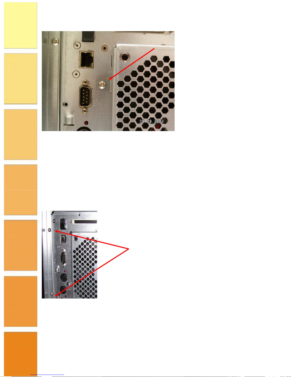
Rear View of the unit
. The rear connector points of the SCSI unit are show in the following diagram.
The Fibre Channel version is similar except that there are Fibre Channel host ports rather than
SCSI.
FRU replacement
Cooling Fan
The low noise fan is easily removed by unscrewing the single retaining screw shown in the
diagram below and then sliding up the fan assembly and pulling it outwards whilst detaching the
fan power connector at the bottom of the backplane.
Host Ports
Power on Switch
Ethernet
RS-232
PSU Input 1
Optional PSU Input 2
Page 13
SAFEStor User Guide
Page 8
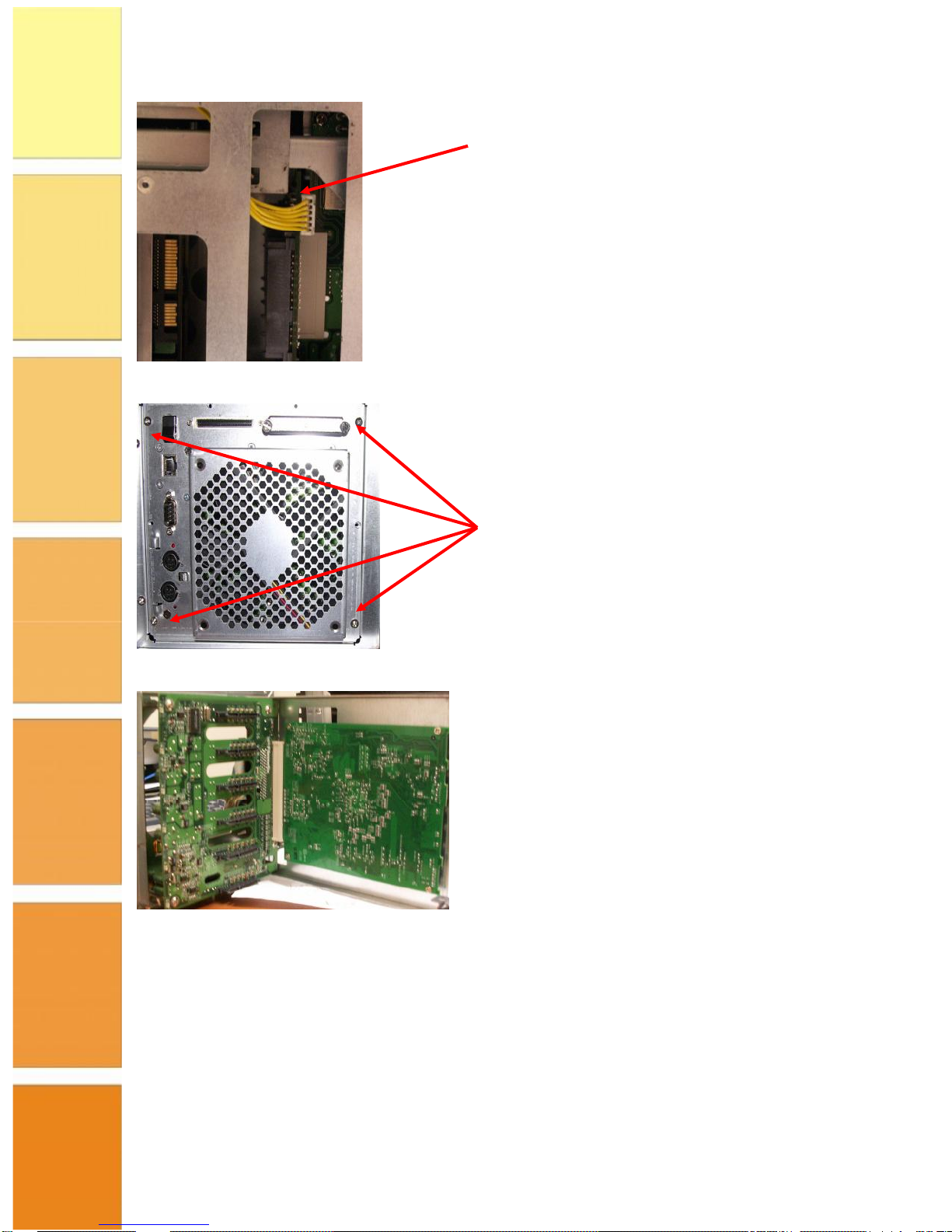
RAID Controller
To gain access to the RAID controller it is necessary to remove the backplate assembly. The
RAID controller is mounted horizontally above the drive bays and is attached to the rear panel.
To remove the controller follow the steps outlined below:
1. Remove drives from backplane.
2. Remove the black plastic side panel by removing the two screws at the left (as viewed
from the rear) and slide it out.
3. Unclip the LCD panel connector from the backplane
Page 14
SAFEStor User Guide
Page 9
4. Remove the four securing screws and remove the assembly
5. Detach the controller from the assembly by removing the four mounting screws.
Drive Carrier
The drives are mounted in purpose designed caddies. The caddies are designed for hot swap operation
with a damping handle and EMI shielding. Status information is conveyed via light pipe. Removal of the
drive carrier is achieved by pressing on the upper part of the handle.
Page 15

SAFEStor User Guide
Page 10
The drives are mounted from the underside of the drive caddy by the four screws shown in the
diagram above.
Drive Mounting Screws
Page 16

SAFEStor User Guide
Page 11
Chapter 3 – Initial Configuration
This Chapter describes how to install the hardware and how to connect to and access the RAID
Controller.
Attaching the SCSI Cables to XRX-2PSQX-651-U4
There are two SCSI ports on the rear of the XRX-2PSQX-651-U4 enclosure. Attach the SCSI
cable (or 2 cables if required) to the SCSI ports.
NOTE: If only one SCSI cable is connected to the enclosure, you must install a SCSI
terminator.
Attaching the Fibre Channel Cables to
XRX-2PSQX-652-FC
There are two Fibre channel SFP Ports on the rear of the XRX-2PSQX-652-FC enclosure at the
rear of the unit. Insert the SFP adapters and then attach the FC cabling to these ports.
Accessing the RAID Controller
Following the hardware installation, the RAID subsystem disk drives must be configured and the
volume sets initialized, before they are ready to use. This is carried out using one of the
following methods:
•
VT100 terminal connected through the RAID subsystem serial port.
•
Firmware-embedded TCP/IP & web browser-based RAID manager via the 10/100
Ethernet LAN port.
The embedded RAID manager provides complete control and management of the RAID
subsystem, eliminating the need for additional hardware or software.
NOTE: The RAID subsystem must only be accessed through one method at a time.
VT100 terminal (via serial port)
The serial port located at the rear of the unit can be used in VT100 mode. The interface cable
provided connects the RS232 port to a PC. The embedded RAID management interface can
access the array through the RS-232 port. You can attach a VT-100 compatible terminal or a PC
running a VT-100 terminal emulation program to the serial port to access the text-based Set-up
Menu.
RAID subsystem RS-232C Port Configuration
To ensure proper communications between the RAID subsystem and VT-100 Terminal
Emulation program, use the following communication settings:
Page 17

SAFEStor User Guide
Page 12
Connection Null-modem cable
Baud Rate 115,200
Data bits 8
Stop 1
Flow Control None
By connecting a VT100 terminal, or a PC operating in an equivalent terminal emulation mode,
all RAID subsystem monitoring, configuration and administration functions can be carried out.
There is a wide variety of Terminal Emulation packages available, such as Hyperterm. Open the
Terminal Emulator of your choice and configure the Settings of the Terminal port as shown in
the Terminal Requirements table above.
When the VT100 Terminal set-up is complete, you can press the " X " key (on your Terminal) to
link the RAID subsystem and Terminal together. The disk array Monitor Utility screen is
displayed on your VT100 Terminal.
Please refer to Chapter 5 to continue with the configuration of the unit using the VT-100
terminal software.
Web browser -based RAID manager
Firmware-embedded web browser RAID manager is a HTTP–based application, which utilizes
the browser installed on your operating system. You can use the Ethernet LAN port (see Chapter
2 for location of components) to configure the subsystem without any additional software or
drivers.
You can manage the RAID subsystem remotely without adding any user specific software
(platform independent) via standard web browsers connected directly to the 10/100 Ethernet
RJ45 LAN port.
To configure the RAID subsystem on a local or remote machine, you need to know its IP
Address. The IP address is detailed on the Product Documentation and Quality Sheet provided
with the unit.
To launch the TCP/IP & Web Browser-based RAID manager, enter:
http://[IP Address]
NOTE: You must be logged-in as administrator with local admin rights on the workstation to
remotely configure RAID subsystem. The user name and password are case sensitive. The
default values are:
User Name: “admin”
Password: “0000”
Page 18

SAFEStor User Guide
Page 13
Web browser -based RAID manager via HTTP Proxy
The browser based RAID manager can be accessed via a HTTP Proxy. The RAID System comes
with proxy software for Windows based host systems.
To run the proxy software, double click on the executing file archttp.exe. The Archttp dialog
box appears. This allows a HTTP session to be established via the serial port. Connect the
supplied serial cable to an unused com port on the server and enter the com port number in the
dialog shown in the diagram below.
The Parameters for the General Setting are:
•
TCP Port value = 1 ~ 65535.
•
RAID Connected to value = 1 ~ 10 where 1 for COM1, 2 for COM2 and so on...
•
BaudRate value = {2400, 4800, 9600, 19200, 38400, 57600, 115200}
NOTE: The RAID controller default baud rate is 115200.
When the program starts running, the following window appears:
To start the ArcHttp Proxy Server web-browser management, click Start.
Type the User Name and Password when prompted. The RAID controller default User Name is
"admin" and the Password is "0000". After entering user name and password, press Enter to
start-up the Http Proxy Server. The RAID Management software is now accessible.
Page 19

SAFEStor User Guide
Page 14
Configuration Menu Tree
1
The following diagram details the menu structure of the RAID manager, which can be accessed
via the RS-232 serial port and Ethernet LAN port.
NOTE: Alert by Email Configuration can only be set in the web-based configuration
Front Panel Operation
The system can also be configured from the front panel display. It is recommended that detailed
configuration is performed using normal keyboard or mouse input rather than through the front
panel, however the display is useful for setting up IP addresses prior to more involved
configuration and reading status information. Interaction with the keypad is achieved by using
the four buttons shown in the following diagram:
1
Note the firmware tree may vary with different firmware releases, the above is based on V1.38 code.
Page 20

SAFEStor User Guide
Page 15
The four buttons are designated:
Enter – Selects a menu option
Esc – Backs up a level
↓ - Moves forward to next field
↑ - Moves backward to next field
The button correspondence is as follows:
The default password is “0000” which may be entered through the panel.
Page 21

SAFEStor User Guide
Page 16
Chapter 4 – Configuration Using Web Module
The RAID Controller of the Storage Enclosure can be configured and managed using the Web
based RAID management software. This chapter describes how to use the Web based
software. For information on accessing the Web based RAID Management Software refer to
Chapter 3.
NOTE: The following screens are taken from the SCSI product, the Fibre Channel
version will differ slightly (mainly in the area of channel configuration).
Initial Configuration
When you log into RAID Manager for the first time (user name = admin, password = 0000)
the overall display screen is shown:
There are six main functions in the RAID Management software:
•
Quick Functions – allows you to quickly build a RAID system with minimal user input
required.
•
RAID Set Functions – allows you to create, delete, modify and expand a RAID set as well
as create and delete hot spare drives and rebuild RAID sets.
•
Volume Set Functions – allows you to create, delete, modify and check volume sets.
•
Physical Drives – allows you to create, modify and delete pass through drives as well as
identify physical drive locations in the enclosure.
•
System Controls – allows you to configure system functions such as alarms,
notifications and passwords, as well as upgrading controller firmware and restarting the
controller.
•
Information – allows you to view RAID set, hardware and system wide information.
Quick Functions
This function allows you to create a RAID Volume set with minimal input. When you click
on the Quick Create link in the navigation panel the
Q u ick C reate
screen is displayed in the
information panel.
Page 22

SAFEStor User Guide
Page 17
This screen contains the following fields:
Total Number of Disks
The total number of disk drives that are available for the
RAID Volume set.
Select RAID Level
Select the RAID level to be applied to the RAID Volume
set from the drop-down list
Maximum Capacity Allowed
The maximum capacity in Gigabytes that is available for
the creation of the RAID Volume set.
Select Capacity
Select the capacity that you wish to apply to the RAID
Volume set.
Volume Initialization Mode
Select whether you want the initialization of the Volume
Set to take place in the Foreground (fastest) or run in
the Background (slow).
Select Stripe Size
Select the stripe size to apply to the RAID Volume Set
from the drop-down list.
To create a Volume Set using the Quick Create function, follow the procedure below:
1. Enter the information in the screen as described in the table above.
2. Select the Confirm The Options check-box.
3. Click Submit to create the RAID Volume Set.
RAID Set Functions
This section describes the RAID Set functions of the RAID Management software. These
functions allow you to create, delete, modify and expand a RAID set as well as create and
delete hot spare drives and rebuild RAID sets.
Create a RAID Set
This function allows you to create a new RAID Set. To create a new RAID Set, follow the
procedure below:
Page 23

SAFEStor User Guide
Page 18
1. From the navigation panel, select Create RAID Set. In the information panel, the list
of the disk drives available for inclusion in the RAID set is displayed.
2. Use the check boxes to select the drives to be included in the RAID Set and then
check the Confirm The Operation check box and click Submit.
3. The RAID Set is created from the selected disk drives.
Delete RAID Set
This function allows you to delete a RAID Set. To delete a RAID Set, follow the procedure
below:
1. From the navigation panel, select Delete RAID Set. In the information panel a list of
available RAID Sets is shown.
2. Using the check box, select the RAID Set to be deleted and then check the Confirm
The Operation check box and click Submit.
3. You will be asked to confirm the deletion.
Page 24

SAFEStor User Guide
Page 19
Expand RAID Set
This function allows you to expand a RAID Set by adding one or more disk drives to it. This
means that you do not have to delete an existing RAID Set and recreate it with more drives.
To Expand a RAID Set, follow the procedure below:
1. From the navigation panel, select Expand RAID Set. In the information panel the list
of previously created RAID Sets is displayed.
2. Using the check boxes, select the RAID Set to be expanded and then click Submit.
3. The list of disk drives that are available to be added to the RAID Set is displayed.
4. Using the check boxes, select the disk drive to be added to the RAID Set, then check
the Confirm The Operation check box and click Submit to expand the RAID Set.
Activate RAID Set
This function allows you to activate RAID Sets that are currently not active. Follow the
procedure below to activate a RAID Set:
1. From the navigation panel, select Activate RAID Set. A list of the RAID Sets that can
be activated is displayed in the information panel.
Page 25

SAFEStor User Guide
Page 20
2. Using the check boxes, select the RAID Sets to be activated, then click Submit, to
make the RAID Sets active.
Create Hot Spare
This function allows you to create a Hot Spare drive. The hot spare drive will always be ready
to instantly be used in the event of a disk drive failing in a RAID Set. To create a Hot Spare
drive, follow the procedure below:
1. From the navigation panel, select Create Hot Spare. The list of disk drives that are
available to create a hot spare is shown in the information panel.
2. Using the check boxes, select the drive you wish to use to create the hot spare drive,
then check the Confirm The Operation check box and then click Submit.
3. The Hot Spare drive is created.
Delete Hot Spare
This function allows you to delete a hot spare drive. Once the hot spare drive is deleted, the
disk drive’s status is set to
Free,
and it can be used to create new RAID sets, expand existing
RAID sets etc. To delete a hot spare drive, follow the procedure below:
1. From the navigation panel, select Delete Hot Spare. The list of hot spare drives is
shown in the information panel.
Page 26

SAFEStor User Guide
Page 21
2. Using the check boxes, select the hot spare drive to be deleted, then check the
ConfirmThe Operation check box and then click Submit.
3. Confirm the deletion, and the hot spare is deleted.
Rescue RAID Set
This function allows you to rebuild a RAID set if it has gone off-line. To rescue the RAID set,
follow the procedure below:
1. From the navigation panel, click Rescue RAID Set. In the information panel you are
asked to enter one of the following parameters:
•
RESCUE – use this option to recover a missing or off-line RAID Set.
•
SIGNAT – use this option to regenerate a RAID set signature, if a RAID Set has been
recovered.
Page 27

SAFEStor User Guide
Page 22
2. In the Enter The Keyword text box, type the keyword as required (see 1
above), then check the Confirm The Operation check box and then click Submit.
Volume Set Functions
This section describes the Volume Set functions of the RAID Management software. These
functions allow you to create, delete, modify and check a Volume. A volume set is seen by the
host system as a single logical device. It is organized in a RAID level with two or more
physical disks. RAID level refers to the level of dataperformance and protection of a volume
set.
A volume set capacity can consume all or a portion of the disk capacity available in a raid set.
Multiple volume sets can exist on a group of disks in a raid set. Additional volume sets created
in a specified raid set will reside on all the physical disks in the raid set. Thus, each volume set
on the raid set will have its data spread evenly across all the disks in the raid set.
Create a Volume Set
This function allows you to create a new Volume Set. To create the new Volume Set, follow
the procedure below:
1. From the navigation panel, select CreateVolume Set. The list of RAID sets from
which a Volume Set can be created is displayed in the information panel.
2. Using the check boxes, select the RAID Set that the Volume Set is to be created from
then click Submit.
3. You must then set the attributes to be applied to the Volume Set.
Page 28

SAFEStor User Guide
Page 23
4. This screen has the following attributes that must be assigned:
Member Disks
Displays the number of disks in the RAID set that
the Volume Set is being created from.
Volume RAID Level
Select the RAID Level to apply to the Volume Set
from the drop down list.
Max Capacity Allowed
The maximum capacity allowed for the Volume
Set. This value will vary depending on the number
of disks available and the RAID Set selected.
Select Volume
Capacity
Enter the Volume in Gigabytes that you wish to
assign to the Volume Set.
Volume Initialization
Mode
Select the Initialization Mode to be applied to the
Volume Set. You can choose between Foreground
(fastest) and Background (slowest).
Volume Stripe Size
Select the Stripe Size to be applied to the Volume
Set from the drop down list.
Volume Name
Enter a name for the Volume Set
Volume Cache Mode
Select the Cache Mode to be applied to the
Volume Set from the drop down box.
Tagged Command
Queuing
Select whether you want Tagged Command
Queuing enabled or disabled.
Max SCSI Speed
Select the maximum SCSI speed that is to apply
to the Volume Set from the drop down list.
SCSI Channel:SCSI
ID:SCSI Lun
Using the drop down lists, select the SCSI
Channel, SCSI ID and SCSI Lun to be assigned to
the Volume Set.
Page 29

SAFEStor User Guide
Page 24
5. When all the above attributes have been assigned, check the ConfirmThe Operation
check box then click Submit.
6. The Volume Set is created.
NOTE: This operation may take some time depending on the RAID type selected and the
size of the Volume Set.
Delete Volume Set
This function allows you to delete a Volume Set. To delete a Volume Set, follow the
procedure below:
1. From the navigation panel, select Delete Volume Set. The list of previously created
Volume Sets is shown in the information panel.
2. Using the check boxes, select the Volume Set that is to be deleted, then check the
ConfirmThe Operation check box and then click Submit.
3. Confirm the deletion when prompted to delete the Volume Set.
Modify Volume Set
This function allows you to modify a previously created Volume Set. To modify a Volume
Set, follow the procedure below:
1. From the navigation panel, select Modify Volume Set. The list of created Volume
Sets is shown in the information panel.
Page 30

SAFEStor User Guide
Page 25
2. Using the check boxes, select the Volume Set that you wish to modify then click
Submit. The attributes for the selected Volume Set are displayed.
3. This screen has the following attributes that can be modified:
Volume Name
Enter a name for the Volume Set
Max Capacity
Allowed
The maximum capacity allowed for the Volume Set. This value will vary
depending on the number of disks available and the RAID Set selected.
Volume Capacity
Enter the Volume in Gigabytes that you wish to assign to the Volume Set.
Volume Initialization
Mode
Select the Initialization Mode to be applied to the Volume Set. You can
choose between Foreground (fastest) and Background (slowest).
Volume RAID Level
Select the RAID Level to apply to the Volume Set from the drop down list.
Volume Stripe Size
Select the Stripe Size to be applied to the Volume Set from the drop
down list.
Volume Cache Mode
Select the Cache Mode to be applied to the Volume Set from the drop
down box
Tagged Command
Queuing
Select whether you want Tagged Command Queuing enabled or disabled.
Max SCSI Speed
Select the maximum SCSI speed that is to apply to the Volume Set from
the drop down list.
SCSI Channel:SCSI
ID:SCSI Lun
Using the drop down lists, select the SCSI Channel, SCSI ID and SCSI
Lun to be assigned to the Volume Set.
4. When you have made the modifications to the Volume Set attributes, check the
Confirm The Operation check box and then click Submit. The changes are applied to the
Volume Set.
Check Volume Set
Page 31

SAFEStor User Guide
Page 26
This function allows you to verify the correctness of the redundant data in a volume set. For
example, in a system with dedicated parity, volume set check means computing the parity of
the data disk drives and comparing the results to the contents of the dedicated parity disk
drive. The checking percentage can also be viewed by clicking on Raid Set Hierarchy in the
main menu.
To carry out the consistency check, follow the procedure below:
1. From the navigation panel, select Check Volume Set. The list of available Volume
Sets is displayed in the information panel.
2. Using the check boxes, select the Volume Set to do the consistency check on and click
Submit to start the check.
Stop Volume Set Check
This function allows you to stop a consistency check on a Volume Set. To stop a consistency
check on a Volume Set, follow the procedure below:
1. From the navigation panel, select Stop Volume Set Check. The list of Volume Sets
that have consistency checks running is displayed in the information panel.
2. Using the check boxes, select the Volume Set that you wish to stop the consistency
check for. Click Submit to stop the consistency check.
Physical Drives
This section describes the Physical Drives functions of the RAID Management software.
These functions allow you to create, modify and delete Pass Through Drives and also
allow you to identify the location of the physical disk drive in the enclosure.
Create Pass Through
This function allows you to create a Pass Through Disk Drive. A Pass-Through Disk is not
controlled by the internal RAID subsystem firmware and thus cannot be a part of a volume
set. The disk is available to the operating system as an individual disk. It is typically used on a
system where the operating system is to be on a disk not controlled by the RAID firmware.
To create a pass through drive, follow the procedure below:
1. From the navigation panel, select Create Pass Through. The list of disk drives that
are available to create pass through disks is displayed in the information panel.
Page 32

SAFEStor User Guide
Page 27
2. Using the check boxes, select the disks that you want to assign as a pass through disk.
3. Assign the attributes to the pass through drive by specifying the following information:
Volume Cache Mode
Select the Cache Mode to be applied to the Pass
Through Drive using the drop down list.
Tagged Command Queuing
Select whether to enable or disable tagged command
queuing using the drop down list.
Max SCSI Speed
Select the maximum SCSI speed to be applied to the
Pass Through Drive using the drop down list.
SCSI Channel:SCSI_ID:SCSI_Lun
Assign the SCSI Channel, SCSI ID and SCSI Lun to the
Pass Through Drive using the drop down list.
4. Once the attributes have been set, check the Confirm The Operation check box
and then select Submit to create the Pass Through Disk.
Modify Pass Through
This function allows you to modify the attributes of an existing Pass Through Disk. To
modify a Pass Through Disk, follow the procedure below:
1. From the navigation panel, select Modify Pass Through. The list of available Pass
Through Disks is displayed in the navigation panel.
2. Using the check boxes, select the Pass Through Drive you wish to modify and click
Submit.
3. The attributes for the selected Pass Through Drive are displayed in the information
panel.
Page 33

SAFEStor User Guide
Page 28
4. The following attributes can be modified on this screen:
Volume Cache Mode
Change the Cache Mode to be applied to the Pass Through Drive
using the drop down list.
Tagged Command Queuing
Change whether to enable or disable tagged command queuing
using the drop down list.
Max SCSI Speed
Change the maximum SCSI speed to be
applied to the Pass Through Drive using the
drop down list.
SCSI
Channel:SCSI_ID:SCSI_Lun
Assign a new SCSI Channel, SCSI ID and SCSI Lun to the Pass
Through Drive using the drop down list.
5. Once the changes have been made to the attributes of the Pass Through Drive, check
the Confirm The Operation check box and then click Submit to make the changes to the
Pass Through Drive.
Delete Pass Through
This function allows you to delete a Pass Through Drive. Once the Pass Through Drive has
been deleted the disk status is set to
Fre e
and it is again available to be used in the creation of
RAID Sets, Hot Spare Drives etc. To delete a Pass Through Drive, follow the procedure
below:
1. From the navigation panel, select Delete Pass Through. The list of available Pass
Through Drives is shown in the information panel.
Page 34

SAFEStor User Guide
Page 29
2. Using the check boxes, select the Pass Through Drive you wish to delete. Check the
Confirm The Operation check box and then click Submit to delete the Pass Through Drive.
Identify Drive
This function allows you to see where a disk drive is physically located within the storage
enclosure by making the drives LED flash on the front of the enclosure. To identify a drive,
follow the procedure below:
1. From the navigation panel, select Identify Drive. The list of all available disk drives
is shown in the information pane.
2. Using the check boxes, select the drive you wish to identify, then click Submit. The
LED for the disk drive will start to flash red on the front of the storage enclosure.
3. To stop the LED from flashing, click on any function in the navigation panel.
Page 35

SAFEStor User Guide
Page 30
System Controls
This section describes the System Controls functions of the RAID Management Software. These
functions allow you to configure alarms, notifications and passwords, as well as upgrading
controller firmware and restarting the controller.
System Configuration
This function allows you to set system wide parameters. To set the system parameters, follow this
procedure:
1. From the navigation panel, select System Config. The system configuration attributes are
displayed in the information panel.
2. The following system attributes can be set from this screen:
System Beeper Setting
Select whether you want the audible alarm beeper
enabled or disabled using the drop down list.
Background Task
Priority
Set the priority level you wish to apply to
tasks running in the background such as Initialization
etc. using the drop down list.
Terminal Port
Configuration
Set the Baud Rate and Stop Bits parameters
for Terminal Emulation using the drop down lists.
JBOD/RAID
Configuration
Set whether you want the system to run as a
JBOD or a RAID system using the drop down list.
Max SATA Mode
Supported
Set the maximum SATA mode that the system
Page 36

SAFEStor User Guide
Page 31
can support from the drop down list.
HDD Read Ahead
Cache
Sets the drives to read in more data than requested
in anticipation of a subsequent request for the data
Stagger Power On
Control
This setting allows the drives to spin up in 0.5 second
increments (from 1 second onwards). The current
default setting is 0.4 seconds
HDD SMART Status
Polling
This function will poll the drives for SMART status
Disk Capacity
Truncation Mode
Select how the disk capacity is to be truncated. For
example, if you select
M ultiples of 10G
, all disk
capacities will be rounded down to the nearest 10G.
3. Once all the attributes have been set, check the Confirm The Operation check box and
then click Submit to set the System Configuration parameters.
U320 SCSI Target Configuration
This function allows you to configure U320 SCSI targets. To configure U320 SCSI Targets,
follow the procedure below:
1. From the navigation panel, select U320 SCSI Target Configuration. A list of U320
SCSI targets is displayed in the information pane.
2. Using the drop down list, select whether you want to Enable or Disable the Quick Arbitration
Select or automatically step down to U160 transfer rates.
3. Check the Confirm The Operation check box, then click Submit.
EtherNet Config
This function allows you to configure the Ethernet port for the enclosure. To configure the
Ethernet port, follow the procedure below:
1. From the navigation panel, select EtherNet Config. The Ethernet parameters are
displayed in the information panel.
Page 37

SAFEStor User Guide
Page 32
2. The following parameters can be set from this screen:
DHCP Function
Select whether you want to enable or disable
DHCP functionality on the enclosure using
the drop down list.
Local IP Address
Enter the local IP address in the boxes (if
DHCP is disabled)
Gateway IP Address
Enter the Gateway IP address in the boxes
Subnet Mask
Enter the Subnet Mask address in the boxes
HTTP Port Number
Enter the HTTP Port Number in the box.
Telnet Port Number
Enter the Telnet Port Number in the box.
Current IP Address
Displays the current IP address.
Current Gateway IP
Address
Displays the current Gateway IP address.
Current Subnet Mask
Displays the current Subnet Mask.
EtherNet MAC
Address
Displays the MAC address of the unit.
3. Once the parameters above have been set, check the Confirm The Operation
check box and then click Submit.
Alert By Mail Configuration
This function allows you to configure the system to send an email to specified email addresses
when an event occurs. To configure the Alert By Mail function, follow the procedure below:
1. From the navigation panel, select Alert By Mail Config. The email alert parameters are
displayed in the information panel.
Page 38

SAFEStor User Guide
Page 33
2. The following parameters can be set from this screen:
SMTP Server IP
Address
Enter the IP address of the SMTP server to be used for email
notifications.
Sender Name
Enter a name that will displayed to the person
receiving the email alert.
Mail Address
Enter the email address that will appear as
the Mail From address for the email alert.
Account
Enter the account name (user name) for the
email notification account on the email server.
Password
Enter the password for the email notification
account on the email server.
MailTo Name 1 to 4
Enter up to 4 names that email event notifications will be sent
to.
Mail Address
Enter the email address of the person named
in the
Mail To Name X
box.
Event Notification
Configuration
Select the level of events that will be notified
to the specified email addresses.
Notification For No
Events
Check this check box if you want a notification sent when no
events occur in a 24 hour period (could indicate that the system
has stopped for some reason).
Page 39

SAFEStor User Guide
Page 34
3. Once all the parameters have been set, check the Confirm The Operation check box and
then click Submit to configure email notification.
SNMP Configuration
This function allows you to configure SNMP settings for the RAID Controller. To configure the
SNMP settings, follow the procedure below:
1. From the navigation panel, select SNMP Configuration. The SNMP attributes will be
displayed in the information panel.
2. This screen contains the following fields:
SNMP Trap Configurations Enter the IP Address and Port Number of the
SNMP traps.
SNMP System Configurations
Enter the SNMP System parameters here.
Enter a Community, Contact, Name and Location
SNMP Trap Notification
Configurations
Select the level of events for which you wish
SNMP traps sent using the check boxes.
Page 40

SAFEStor User Guide
Page 35
3. Once the above information has been added, check the Confirm The Operation
check box and then click Submit to set the SNMP Configuration parameters.
NTP Configuration
Use this screen to input the parameters of the Network Time Protocol (NTP) server to use
for time synchronization.
View Events/Mute Beeper
This function allows you to view events generated by the RAID controller. Viewing events
will also mute the alarm beeper. To view events, select View Events/Mute Beeper from
the navigation panel. The event log is opened and you can view all the generated events.
Page 41

SAFEStor User Guide
Page 36
This screen shows the date and time that the events took place, the device that the event
was generated from and the type of the event etc.
Generate Test Event
This function allows you to generate a test event. This is used to ensure that your
event notification process is working correctly. Select Generate Test Event from
the navigation panel to bring up the Generate Test Event screen.
Generate the test event by checking the Confirm The Operationcheck box and then click
Submit.
Clear Event Buffer
This function allows you to clear the event buffer. Select Clear Event Buffer from the
navigation panel to bring up the Clear Event Buffer screen.
To clear the event buffer, check the Confirm The Operation check box and then click
Submit.
Modify Password
This function allows you to change the password2 used to log into the RAID Controller. To
modify the password, follow the procedure below:
2
If the password is changed from the default ensure that a note is keep in a safe secure place. Do not lose this
password.
Page 42

SAFEStor User Guide
Page 37
1. From the navigation panel, select Modify Password. The Modify Password screen
is displayed in the information panel.
2. Enter the original password and then enter the new password twice.
3. Check the Confirm The Operation check box and then click Submit.
Upgrade Firmware
This function allows you to upgrade the firmware on the RAID controller. To upgrade the
firmware, follow the procedure below:
1. From the navigation panel, select Upgrade Firmware. The upgrade firmware
screen is displayed in the information panel.
2. Enter the path and filename of the latest firmware image or click Browse and
search for the file.
3. Check the Confirm The Operation check box and then click Submit to start the
firmware upgrade.
Restart Controller
This function allows you to restart the controller. To restart the controller, select Restart
Controller from the navigation panel and the restart controller screen is displayed in the
information panel.
Page 43

SAFEStor User Guide
Page 38
To restart the controller, check the Confirm The Operation check box and then click
Submit.
Information
These functions allow you to view general information relating to the RAID sets, system
and hardware.
RAID Set Hierarchy
This function allows you to view general information relating to the RAID sets created on
the system. To view the RAID set hierarchy, select RaidSet Hierarchy from the
navigation panel. Details about the RAID sets created on the system are displayed in the
information panel.
This screen shows the list of RAID Sets created on the system along with details relating to
these RAID sets, such as the disk drives used in the RAID set, Volume sets created from the
RAID sets, the status of the Volume sets and the capacity of each RAID set.
At the bottom of the screen is a list of all the disk drives on the system showing what each
disk is used for, its capacity and the model of the disk drive.
NOTE: For more detailed information on a RAID Set, Volume Set or Disk Drive, click on
Page 44

SAFEStor User Guide
Page 39
its hyperlinked name.
System Information
This function displays detailed information about the RAID Controller. To view the
detailed information, select System Information from the navigation panel. The system
information is displayed in the information panel.
Hardware Monitor
This function allows you to view hardware information relating to the storage enclosure.
To view the hardware information, select Hardware Monitor from the navigation panel.
The hardware information is displayed in the information panel.
Page 45

SAFEStor User Guide
Page 40
Page 46

SAFEStor User Guide
Page 41
Chapter 5 – Configuration Using VT100
This chapter describes how to configure the RAID Controller using a VT100 terminal emulation
program. For details on how to access the VT100 menus, refer to Chapter 3.
Keyboard Navigation
The following key–functions are used to navigate through the VT-100 RAID configuration
utility.
Key Function
Arrow Key Move cursor
Enter Key Submit selection function
ESC Key Return to previous screen
L Key Line draw
X Key Re-draw
Login
Before accessing the main menu, you are required to enter a password. The default password is
0000. Once you are logged in you can change the password via the Change Password option
under the RAID Set Function menu item.
Main M enu
The main menu provides access to all the available functions. Refer to page 14 for a view of the
complete menu structure. Use the arrow keys to move up and down through the menu, then press
Enter to select a menu item or Esc to go back to the previous menu.
Quick Volume/Raid Setup
Create a default configuration based on the number of physical disks
installed
Raid Set Functions
Create a customized raid set
Volume Set Functions
Create a customized volume set
Physical Drive Functions
View individual disk information
Raid System Function
Set the raid system configurations
U320 SCSI Target Config
Enable or Disable U320 SCSI Targets
Ethernet Configuration
Configure the Ethernet port for the RAID enclosure.
View System Events
View all system events in the system
Clear Event Buffer
Clear all system event information
Hardware Monitor
View all system hardware information
System Information
View the controller system information
Page 47

SAFEStor User Guide
Page 42
Quick Volume/Raid Setup
Quick Volume/Raid Set-up is the fastest way to prepare a raid set and volume set. It can be
completed with just a few keystrokes. Although drives of different capacity may be used in
the raid set, the smallest capacity drive in the RAID set is used as the capacity of all disk
drives in the RAID set.
RAID Level:
The total number of physical drives in a specific RAID set determine the RAID levels that
can be implemented. Press Enter on Quick Volume/Raid Set-up from the main menu; all
possible RAID levels will be displayed, as shown below:
Select Capacity:
A single volume set is created that consumes all or a portion of the disk capacity available
in the RAID set. To define the capacity of the volume set, use the Available Capacity
screen. The default value for the volume set is displayed. Use the arrow keys to modify the
volume set capacity and press Enter to accept the value. If it only uses part of the raid set
capacity, you can use the Create Volume Set option to define additional volume sets.
Stripe size
This parameter sets the size of the stripe written to each disk in a RAID 0, 1, 0+1, 5, or 6
logical drive. You can set the stripe size to 4 KB, 8 KB, 16 KB, 32 KB, 64 KB, or 128 KB.
A larger stripe size provides better read performance, especially if your computer
processes mostly sequential reads. However, if your computer processes a lot of random
read requests, a small stripe size should be selected.
Page 48

SAFEStor User Guide
Page 43
Press Yes in the Create Vol/Raid Set dialog box, the raid set and volume set will start to
initialize.
Raid Set Function
RAID Sets can be configured manually from the RAID Set Function menu. From this
function you can manually create, delete, expand and activate a raid set.
Create Raid Set
To create a RAID Set, follow the procedure below:
1. Select Raid Set Function from the main menu.
2. Select Create Raid Set from the Raid Set Function menu.
3. The Select Drive For Raid Set window is displayed listing the available drives.
Use the arrow keys to select specific physical drives.
4. Press Enter to select the drives for inclusion3 in the RAID Set. Repeat this step, for
all drives you want to include in the RAID set. When you have finished selecting the
drives to be included in the Raid Set, press Esc. Press Yes to confirm the creation.
3
Selected drives are shown by an asterix
Page 49

SAFEStor User Guide
Page 44
5. The Edit The Raid Set Name option appears. Enter a name for the RAID Set by
entering 1 to 15 alphanumeric characters. The default raid set name is Raid Set #.
Delete Raid Set
To delete a RAID set, select the raid set number you want to delete from the Select Raid
Set to Delete option. The Delete Raid Set screen appears, select Yes to delete it. A second
confirmation screen appears. Select Yes again to reconfirm the deletion.
CAUTION: Deleting a Raid Set is a destructive action that will cause the loss of all data
existing on the Raid Set.
Expand Raid Set
Instead of deleting a raid set and recreating it with additional disk drives, the Expand
Raid Set function allows you to add drives to an existing raid set.
Page 50

SAFEStor User Guide
Page 45
To expand a raid set, follow the procedure below:
1. Click Expand Raid Set. If there are available disks, the Select Drives For
Raid Set Expansion menu appears.
2. Select the Raid Set and then select the disk.
3. A confirmation screen appears. Select Yes to confirm.
The new raid set capacity can be defined as one or more volume sets. Follow the
instructions in the Volume Set Function to create volume sets.
NOTE: Once the Expand Raid Set process has started, you cannot stop it. The process
must be completed.
NOTE: If a disk drive fails during raid set expansion and a hot spare is available, an
auto-rebuild operation will occur upon completion of the raid set expansion.
Activate Incomplete Raid Set
When a drive is removed while the RAID subsystem is powered-off, the raid set state will
change to
Incom plete S tat e
. To continue to work when the RAID subsystem is powered on,
you can use the Activate Raid Set option to activate the raid set. When this process is
complete, the Raid State will change to
D egraded M o d e
.
Create Hot Spare
Selecting the Create Hot Spare option from the Raid Set Function menu, brings up a list
of all physical disks which are available:
Page 51

SAFEStor User Guide
Page 46
1. Scroll to the required disk using the arrow keys.
2. Press Enter to select a disk.
3. Select Yes in “Create Hot Spare?” to designate the drive as a hot spare.
Delete Hot Spare
This option allows you to delete a hot spare drive.
1. Scroll to the hot spare drive to be deleted using the arrow keys.
2. Press Enter to select the drive
3. Select Yes in “DeleteHot Spare?” to delete the hot spare.
Raid Set Information
To display Raid Set information, scroll to the desired Raid Set number and press
Enter. The Raid Set Information is displayed.
The following information is shown for the RAID set:
Page 52

SAFEStor User Guide
Page 47
Raid Set Name
Shows the name of the Raid Set
Member Disks
Shows the number of disks belonging to the Raid
Set.
RAID State
Shows the status of the Raid Set.
Total Capacity
Shows the total capacity available in the Raid Set.
Free Capacity
Shows the non-allocated capacity that can be used
to define more Volume Sets.
Min Member Disk
Size
Shows the capacity of the smallest disk drive in
the Raid Set.
Member Disk
Channel
Shows the disks that belong to the Raid Set by
naming the channel/slot they are attached to.
Volume Set Function
A Volume Set is seen by the host system as a single logical drive. It is organized in a
RAID level with two or more physical drives. RAID level refers to the level of data
performance and protection of a Volume Set.
A Volume Set capacity can consume all or a portion of the drive capacity available in a
Raid Set. Multiple Volume Sets can exist on a group of drives in a Raid Set. Additional
Volume Sets created in a specified Raid Set will reside on all the physical drives in the
Raid Set. Therefore, each Volume Set on the Raid Set will have its data spread evenly
across all drives in the Raid Set.
The volume set features are as follows:
•
Volume sets of different RAID levels may co-exist on the same raid set.
•
Up to 16 volume sets can be created in a raid set.
•
The maximum addressable size of a single volume set is 2 TB.
Create Volume Set
To create a volume set, follow the procedure below:
1. Select Volume Set Function from the Main menu.
2. Choose Create Volume Set from Volume Set Function menu.
3. The Create Volume From Raid Set option appears. This screen displays the
available raid sets. Scroll to the required raid set and press Enter.
Page 53

SAFEStor User Guide
Page 48
4. The Volume Creation option is displayed showing the current settings for the
volume set. The Volume Creation option allows you to select the Volume Name, RAID
level, Capacity, Stripe Size, SCSI or FC ID/LUN, Cache Mode, Tag Queuing and Max
Sync Rate. You can modify the default values in this menu by scrolling to the required
option and pressing Enter. Press Esc to save the value and return to the menu.
The following table shows the attributes that can be modified:
Volume Name
The default volume name will always appear as Volume
Set. #. You can rename the volume set providing it does
not exceed the 15-character limit.
RAID Level
To set the RAID level for a Volume Set, highlight
Raid Level and press Enter. The available RAID levels for
the current Volume Set are displayed. Select the required
RAID level and press Enter to confirm.
Capacity
The maximum size of the volume is always the
default setting. You can increase or decrease the capacity
using the UP and DOWN arrow keys.
Page 54

SAFEStor User Guide
Page 49
Each volume set can have a capacity which is less
than, or equal to, the total capacity of the raid set
on which it resides.
Stripe Size
This parameter sets the size of the segment
written to each disk in a RAID 0, 1, 0+1, 5 or 6
logical drive. You can set the stripe size to 4 KB, 8
KB, 16 KB, 32 KB, 64 KB, or 128 KB.
SCSI Channel
Your system has two Ultra 160 or Ultra 320 SCSI
channels. Select SCSI Channel. The Select SCSI
Channel option appears. Select the channel
number and press Enter to confirm.
SCSI ID
Each SCSI device attached to the SCSI card, as well as the
HBA card itself, must be assigned a unique SCSI ID number.
An LVD SCSI channel can connect up to 15 devices. The
Volume Set will appear as a large SCSI device. You must
assign an ID from a list of SCSI IDs. ID 7 is normally
reserved for the HBA.
SCSI LUN
Each SCSI ID can support up to 8 LUN’s. Most SCSI host
adapters treat each LUN like a SCSI disk.
Cache Mode
You can set the cache mode to: Write-Through Cache
or Write-Back Cache.
Tag Queuing
Enabling Tag-Queuing is useful for enhancing overall system
performance under multi-tasking operating systems. The
Command Tag (Drive Channel) function controls the SCSI
command tag queuing support for each drive channel. This
function should remain enabled and should only be disabled
when using older SCSI host cards that do not support
command tag queuing.
Max Sync Rate
The RAID subsystem 320 MB/sec as the highest data
transfer rate for the Ultra 320 system.
5. When the volume set parameters are modified, press Esc to confirm. A Fast
Initialization option will be displayed.
•
Select Foreground to start Fast Initialization of the volume set.
•
Select Background to start Normal Initialization of the volume set.
Page 55

SAFEStor User Guide
Page 50
6. Repeat steps 3 to 5 to create additional volume sets.
7. The initialization progress is displayed at the bottom of the screen.
Delete Volume Set
To delete a Volume set, select the Delete Volume Set option by pressing Enter. The list of
all available RAID sets is displayed. Scroll to a RAID Set, then press Enter to show all
Volume Sets in the raid set. Select the Volume Set number you wish to delete and press
Enter to delete it.
CAUTION: Deleting a Volume Set is a destructive action that will cause the loss of
data existing in the Volume Set.
Modify Volume Set
Use this option to modify a volume set. To modify a Volume Set, select the Modify
Volume Set option, then press Enter. The list of all available RAID sets is displayed.
Scroll to the required Raid Set number and, press Enter to show all Volume Sets
associated with the RAID set.
Select the Volume Set you which to modify from the list and press Enter to modify it.
Page 56

SAFEStor User Guide
Page 51
To change a Volume set attribute, scroll to the attribute and press Enter. Make the
modification and then press ESC to save the change. The following attributes can be
modified:
Volume Name
The default volume name will always appear as Volume
Set. #. You can rename the volume set providing it does
not exceed the 15-character limit.
RAID Level
To set the RAID level for a Volume Set, highlight Raid
Level and press Enter. The available RAID levels for the
current Volume Set are displayed. Select the required RAID
level and press Enter to confirm.
Capacity
The maximum size of the volume is always the
default setting. You can increase or decrease the
capacity using the UP and DOWN arrow keys.
Each volume set can have a capacity which is less
than, or equal to, the total capacity of the raid set
on which it resides.
Stripe Size
This parameter sets the size of the segment
written to each disk in a RAID 0, 1, 0+1, 5 or 6
logical drives. You can set the stripe size to 4 KB,
8 KB, 16 KB, 32 KB, 64 KB, or 128 KB.
SCSI Channel
Select the SCSI channel number and press Enter to confirm.
SCSI ID
Each SCSI device attached to the SCSI card, as well as the
HBA card itself, must be assigned a unique SCSI ID number.
An LVD SCSI channel can connect up to 15 devices. The
Volume Set appears as a large SCSI device. You must
assign an ID from a list of SCSI IDs. ID 7 is normally
reserved for the HBA.
SCSI LUN
Each SCSI ID can support up to 8 LUN’s. Most SCSI host
adapters treat each LUN like a SCSI disk.
Cache Mode
You can set the cache mode to: Write-Through
Cache or Write-Back Cache.
Tag Queuing
Enabling Tag-Queuing is useful for enhancing overall system
performance for multi-tasking operating systems. The
Command Tag (Drive Channel) function controls the SCSI
command tag queuing support for each drive channel. This
function should remain enabled and should only be
disabled when using older SCSI host cards that do
not support command tag queuing.
Page 57

SAFEStor User Guide
Page 52
Max Sync Rate
The RAID subsystem supports 320 MB/sec as the highest
data transfer rate for the Ultra 320 SCSI system.
Check Volume Set
Use this option to verify the correctness of the redundant data in a volume set. For
example, in a system with dedicated parity, volume set check means computing the parity
of the data disk drives and comparing the results to the contents of the dedicated parity
disk drive.
To check a Volume Set, select Check Volume Set, then press Enter. Select a Raid Set
from the list, then press Enter to show all Volume Sets.
Select the Volume Set from the list and press Enter to select it. A confirmation screen is
displayed. Press Yes to start the check.
Stop Volume Set Check
Use this option to stop all Check Volume Set requests.
Display Volume Set Info.
To display Volume Set information, scroll to the desired Volume Set, then press Enter.
The Volume Set Information will be displayed as shown below. You can only view
information for one Volume Set at a time.
Physical Drive
Choose this option from the Main Menu to select a physical disk and perform operations
(described below) on it.
Page 58

SAFEStor User Guide
Page 53
View Drive Information
This option allows you to view details about the physical disks in the RAID subsystem.
Selecting the View Drive Information option displays a list of all disk drives attached to the
controller. Scroll to the desired drive and press Enter. The following information about the
drive is displayed:
Create Pass-Through Disk
A Pass-Through Disk is not controlled by the RAID subsystem firmware and thus cannot
be a part of a Volume Set. The disk is available to the operating system as an individual
disk. It is typically used on a system where the operating system is to be on a disk not
controlled by the RAID subsystem firmware.
To create a Pass Through Disk, select Create Pass Through Disk from the menu. The list
of available disk drives is displayed.
Page 59

SAFEStor User Guide
Page 54
Scroll to a disk drive and press Enter to set the attributes for the Pass Through Drive.
Scroll to the attribute you wish to edit and press Enter. Edit the attribute and then press
ESC to save the change and return to the previous menu.
Modify Pass-Through Disk
This option allows you to modify the Pass-Through Disk Attributes. Tomodify PassThrough Disk attributes, select the Modify Pass-Through Drive option and then press
Enter. All Pass-Through Drives are displayed. Scroll to the required drive and then press
Enter to show the Pass-Through Disk Attributes.
Page 60

SAFEStor User Guide
Page 55
Select the parameter from the list you which to change, press Enter to modify it, then
press ESC to save the change and return to the previous menu.
Delete Pass-Through Disk
To delete a Pass-through drive select Delete Pass-Through Drive, then press Enter. A list
of all Pass Through Drives is displayed. Select the drive you wish to delete and press
Enter.
Identify Selected Drive
To allow you to identify a particular physical drive in the front of the enclosure, the
selected drive LED will flash red to allow you to identify the correct physical drive in the
front of the enclosure when the Identify Selected Device is selected.
Page 61

SAFEStor User Guide
Page 56
RAID System Function
The Raid System Function menu allows you to manage the RAID controller.
Mute The Alert Beeper
The Mute The Alert Beeper function allows you to control the RAID subsystem Beeper.
Select Yes and press Enter in the dialog box to mute the beeper. The beeper will still
activate on the next event.
Page 62

SAFEStor User Guide
Page 57
Alert Beeper Setting
The Alert Beeper function allows you to Disable or Enable the RAID subsystem controller
beeper.
Select Disabled and press Enter to turn the beeper off. Or, select Enable and press
Enter to turn the beeper on.
Change Password
The password option allows you to set or clear the raid subsystem’s password protection
feature. Once the password has been set, you can only monitor and configure the raid
subsystem by providing the correct password.
The password is used to protect the RAID subsystem from unauthorized entry. The
controller will check the password only when entering the Main menu from the initial
Page 63

SAFEStor User Guide
Page 58
screen. The RAID subsystem will automatically go back to the initial screen when it does
not receive any command for twenty seconds.
To disable the password, press Enter (without entering any alphanumeric characters) in
both the Enter New Password and the Re-Enter New Password column. The existing
password will be cleared. No password checking will occur when entering the main menu
from the starting screen.
RAID/JBOD Function
The RAID/JBOD Function allows you to instruct the system as to how it should handle the
drives. RAID will give you the functionality of creating RAID sets and JBOD will treat all
drives as individual drives with no Raid protection.
Background Task Priority
The Background Task Priority function allows you to specify how tasks that run in the
background are prioritized. Select the amount of resources (in percent) to be allocated to
background tasks.
Page 64

SAFEStor User Guide
Page 59
Maximum SATA Mode
The Maximum SATA Mode function allows you to set the maximum SATA mode that the
system can support as well as enabling Native Command Queuing (NCQ). Select the Max
SATA mode from the list and press Enter to select.
HDD Read Ahead Cache
Select the read ahead function to enable pre-fetching of data that has not specifically been
requested in anticipation of subsequent reads for this data. This function may improve
sequential read throughput.
Page 65

SAFEStor User Guide
Page 60
Stagger Power On
This function is used to prevent current surge when powering up all disks simultaneously.
The interval selected is the interval between the power up command issued to each drive in
turn. For example a two second interval ensures that commands are issued to individual
drives every two seconds.
The setting for SAFEStor products should be set to a minimum of 2.5 seconds.
HDD SMART Status Polling
This features allows the controller to take advantage of monitoring SMART information
from the disk drives.
Page 66

SAFEStor User Guide
Page 61
Capacity Truncation
The Capacity Truncation function allows you to select how the disk capacity is to be
truncated. For example, if you select
M u ltiples of 10G
, all disk capacities will be rounded
down to the nearest 10G i.e. if a disk has capacity of 412G then it will appear as having a
capacity of 410G on the system. Select the Capacity Truncation setting from the list and
press Enter to select it. This may be useful if mixing drive vendors with similar capacities
(or newer revision models of similar capacity form the same vendor).
Terminal Port Config.
Page 67

SAFEStor User Guide
Page 62
The Terminal Port Config function allows you to configure the terminal port. From this
screen you can set the Baud Rate and the Stop Bits values. Press Enter to select Baud Rate
or Stop Bit and edit the settings. Press ESC to save the change and return to the previous
menu.
Update Firmware
NOTE: You can update the firmware through the VT100 terminal via the
controller’s serial port.
NOTE: You can update the firmware via the firmware-embedded web browser- based
RAID manager through the controller’s 10/100 Ethernet LAN port.
Page 68

SAFEStor User Guide
Page 63
Restart Controller
This function allows you to restart the controller. Select Restart Controller from the
menu and press Enter. The Restart Controller confirmation screen appears. Select Yes to
restart the RAID controller.
NOTE: Ensure that there is no Host and Drive activity before restarting the controller.
U320 SCSI Target Config
This function allows you to configure U320 SCSI targets. Select U320 SCSI Target
Config from the Main Menu and press Enter.
The list of available U320 SCSI targets is displayed. Scroll to the required SCSI target and
press Enter. Select Disable to disable the SCSI target, or select Enable to enable the SCSI
target.
Page 69

SAFEStor User Guide
Page 64
Ethernet Configuration
These functions allow you to set the controller Ethernet port configuration. You do not
need to create a reserved space on the arrays before the Ethernet port and HTTP service
will function.
Scroll to a parameter in the list and press Enter to open it for editing. Make the necessary
changes and then press ESC to save the changes and return to the previous menu.
DHCP Function
DHCP (Dynamic Host Configuration Protocol) is a protocol that lets network
administrators manage centrally and automate the assignment of IP (Internet Protocol)
configurations on a computer network. When using the Internet's set of protocols (TCP/IP),
in order for a computer system to communicate to another computer system it needs a
unique IP address. Without DHCP, the IP address must be entered manually at each
computer system. DHCP lets a network administrator supervise and distribute IP addresses
from a central point. The purpose of DHCP is to provide the automatic (dynamic)
allocation of IP client configurations for a specific time period (called a lease period) and
to eliminate the work necessary to administer a large IP network.
To manually configure the IP address of the controller, scroll to the Ethernet Configuration
Function and press Enter. The Ethernet Configuration menu appears on the screen. Scroll
to the DHCP Function, then press Enter to show the DHCP setting. Select the Disabled or
Enabled option to enable or disable the DHCP function.
Local IP address
If you intend to set up your client computers manually, make sure that the assigned IP
address is in the same range as your default router address and that it is unique to your
private network. However, we would highly recommend that if you have a network of
computers and the option to assign your TCP/IP client configurations automatically, please
do so. An IP address allocation scheme will reduce the time it takes to set-up client
computers and eliminate the possibilities of administrative errors.
To manually configure the IP address of the controller, scroll to Local IP Address and
press Enter to show the default address setting. You can now reassign the IP address of the
controller. Press ECS when finished to save the IP address and return to the previous
menu.
Page 70

SAFEStor User Guide
Page 65
Http Port Number
This function allows you to set the port number to be used as the HTTP port for the RAID
controller. Select HTTP Port Number and press Enter. Type a new port number and then
press ESC to save the new Port Number and return to the previous menu.
Telnet Port Number
This function allows you to set the port number to be used as the Telnet Port for the RAID
controller. Select Telnet Port Number and press Enter. Type a new port number and then
press ESC to save the new Port Number and return to the previous menu.
Ethernet Address
A MAC address stands for Media Access Control address and is your computer's unique
hardware number. On an Ethernet LAN, it's the same as your Ethernet address. When you
are connected to the Internet from the RAID controller Ethernet port, a correspondence
table relates your IP address to the RAID controller’s physical (MAC) address on the
LAN.
View System Events
This function allows you to view the RAID controller system events information. To view
the events, select View System Events, then press Enter. The RAID subsystem events
screen appears.
Choose this option to view the system events information: Time, Device, Event type,
Elapse Time and Errors. The RAID system does not have a built in real time clock. The
Time information is the relative time from the RAID subsystem being powered on.
Clear Events Buffer
This function allows you to clear the entire events buffer information. To clear the buffer,
select Clear Events Buffer and press Enter, then select Yes and press Enter.
Page 71

SAFEStor User Guide
Page 66
Hardwa re M onitor
The Hardware Monitor Information provides the temperature, of any drives present within
the enclosure. It also provides the temperature, fan speed (chassis fan) and the voltage of
the RAID subsystem. All items are read-only. The warning messages will be indicated
through the Fault LED’s or the alarm buzzer.
Select Hardware Monitor by pressing Enter to view Temperature information.
Press ESC to return to the Main Menu. Select Hardware Monitor again to view further
hardware information.
Page 72

SAFEStor User Guide
Page 67
Sy stem Information
Choose this option to display details of the Main processor, CPU Instruction cache and
data cache size, firmware version, serial number, controller model name, and the cache
memory size. To view the system information, select System Information and then press
Enter.
 Loading...