

Page 1

705P01216
March 2008
Page 2

Phaser® 5500/5550 Printer
Service Manual
Phaser 5500/5550 Printer
Apple®, Bonjour®, ColorSync®, EtherTalk®, Macintosh®, and Mac OS® are trademarks of
Apple Computer, Inc. in the United States and/or other countries.
PCL® is a trademark of Hewlett-Packard Corporation in the United States and/or other countries.
705P01216
Initial Issue
March 2008
Xerox Corporation
XOG Worldwide Product Training and Information
26600 W Parkway
Wilsonville, OR 97070
NOTICE: All service documentation is supplied to Xerox external customers for informational
purpose only. Xerox service documentation is intended for use by certified, product trained service personnel only. Xerox does not warrant or represent that such documentation is complete,
nor does Xerox represent or warrant that it will notify or provide to such customer any future
changes to this documentation. Customer performed service of equipment, or modules, components or parts of suc h equipment may affect the warranty offered by Xerox with respect to
such equipment. You should consult the applicable w arranty for its terms regarding customer or
third party provided serv ice. If the customer services such equipm ent, modules, components
or parts thereof, the customer releases Xerox from any and all liability for the customer actions,
and the customer agrees to indemnify, defend and hold Xerox harmless from any third part y
claims which arise directly or indirectly from such service.
Unpublished rights reserved under the copyright laws of the United States. Contents of this
publication may not be reproduced in any form without permission of Xerox Corporation.
Microsoft®, Vista™, Windows®, and Windows Server™ are trademar ks of M icrosoft Cor poration in the United States and/or other countries.
Novell®, NetWare®, and IPX/SPX™ are trademarks of Novell, Incorporated in the United
States and/or other countries.
SunSM, Sun Microsystems™, and Solaris™ are trademarks of Sun Microsystems, Incorporated in the United States and/or other countries.
UNIX® is a registered trademark in the United States and other countries, licensed exclusively
through X/Open Company Limited.
As an ENERGY STAR® partner, Xerox Corporation has determined that this product meets
ENERGY ST AR guidelines f or energy efficiency. The ENERGY STAR name and logo are registered U.S. marks.
PANTONE® Colors generated may not match PANTONE-identified standards. Consult current
PANTONE Publications for accurate color. PANTONE® and other Pantone, Inc. trademarks are
the property of Pantone, Inc. © Pantone, Inc., 2000.
Copyright protection claimed includes all forms and matters of copyrightable materials and
information now allowed by statutory or judicial law or hereinafter granted, including without
limitation, material generated from the software programs which are displayed on the screen
such as styles, templates, icons, screen displays, looks, etc.
Xerox technical training materials and service manuals are intended for use by authorized
Xerox service technicians and service part ners only and are not for resale. These materials
may not be distributed, copied, or otherwise reproduced without prior written consent from
Xerox Corporation.
XEROX®, CentreWare®, Phaser®, PhaserCal®, PhaserMatch®, PhaserSMART®, TekColor™, PrintingScout™, and Walk-Up® are trademarks of Xerox Cor poration in the United
States and/or other countries.
Adobe® and PostScript® are trademarks of Adobe Systems Incorporated in the United States
and/or other countries.
Initial Issue
03/05/2008
Phaser 5500/5550 Printer Service Manual
Page 3

About this Manual ......................................................................... .. .... ......... .... .. .... .... ..... iii
Organization . ...................................................................................................................i
How to Use this Documentation...................................................................................... iv
Power Safety Precaution s............................................................. .................................. vi
Service Safety Summary............................. .......................... .......................................... vii
Electrostatic Discha rge Precautions................................................. ......................... ..... viii
Service Terms..................................... ......................... ......................... .......................... ix
Symbology and Nomenclature........................................................................................ x
Regulatory Specifications............................................................................... .. .. .... .. .. ..... xiii
Phaser 5500/5550 Printer Overview ............................................................................... xiv
Phaser 5500/5550 Printer Configurations....................................................................... xiv
Parts of the Pr inter .......................................................................................................... xv
Printer Options................................................................................................................ xv
Consumables and Routine Maintenance Items .............................................................. xviii
Printer Specifications ...................................................................................................... xix
Phaser 5500/5550 Printer Menu Map ............................................................................. xxi
ii
i
Introduction
Initial Issue
Phaser® 5500/5550 Printer
March 2008
i
Introduction
Page 4

About this Manual
The Phaser 5500//5550 Printer Ser vice Manual is the p rimar y document used for diagnosing,
repairing, maintaining, and troubleshooting the printer. It is the controlling publication for a service call. Information on its use is found in the introduction of the Service Manual.
To ensure complete underst anding of this product, participation in Xerox Phaser 5500/5550
Service Training is st rongly recommended. To service this product, Xerox certification for this
product is required.
Service Manual Revision
Updates are issued as the system changes or as corrections are identified.
For updates to the Service Manual, Service Bulletins, Knowledge Base, etc., go to:
• Xerox Global Service Net - https://www.xrxgsn.com
• Service Partners - http://www.office.xerox.com/partners
For further technical support, contact your assigned Xerox Technical Suppor t for this product.
Organization
The titles of the sections and a description of the information contained in each section are
contained in the following paragraphs:
Introduction and General Information
This section contains documentation organization, symbology and nomenclature, translated
warnings, safety symbols, regulatory specifications, and general information.
Section 1 - Service Call Procedures
This section contains procedures to be taken during a service call on the machine and in what
sequence they are to be completed. This is the entry level for all service calls.
Section 2 - Status Indicator RAPs
This section contains the diagnostic aids for troubleshooting the Fault Code and non-Fault
Code related faults (with the exc eption of image quality problems).
Section 3 - Image Quality
This section contains the diagnostic aids for troubleshooting any image quality problems, as
well as image quality specifications and image defect samples.
Section 4 - Repairs and Adjustments
This section contains all the removal, replacement, and adjustment procedures.
Repairs
Repairs include procedures for removal and replacement of spare parts listed in the Parts List.
Use the repair procedures for the correct order of removal and replacement, for warning, cautions, and notes.
Initial Issue
Phaser® 5500/5550 Printer
Adjustments
Adjustments include procedures for adjusting the parts that must be within specification for the
correct operation of the system. Use the adjustment procedures for the correct sequence of
operation for specifications, warnings, cautions, and notes.
Section 5 - Parts List
This section contains the illustrated Parts List.
Section 6 - General Troubleshooting
This section contains details of embedded Service Diagnostics tests, as well as troubleshooting procedures for system problems not related to a specific fault code.
Section 7 - Wiring Data
This section contains drawings, lists of Plug/Jack locations, and diagrams of the power distribution wire networks in the machine. This section also contains the Block Schematic Diagrams.
Section 8 - Theory of Operation
This section contains detailed functional information on the print engine components.
March 2008
iii
Introduction
About this Manual, Organization
Page 5
How to Use this Documentation
The Service Call Procedures in section 1 des cribe the sequence of activities used during the
service call. The call must be entered using these procedures.
Use of the Circuit Diagrams
Circuit Diagrams (CDs) are included in Section 7 of the Service Manual. All wirenets, with the
exception of power distribution wirenets, are shown on the CDs. The power distribution
wirenets on the CDs will end at the terminal board for the power being distributed. Find the
wirenet for that power and locate the terminal board on the wirenet. Use the wirenet to troubleshoot any power distribution wiring not shown on the CD.
Use of the Block Schematic Diagrams
Block Schematic Diagrams (BSDs) are included in Section 7 (Wiring Data) of the Service Manual. The BSDs provide the functional relationship of the electrical circuitry to any mechanical,
or non-mechanical, inputs or outputs throughout the machine. Inputs and outputs such as
motor drive, mechanical linkages, operator actions, and air flow are shown. The BSDs provides an overall view of how the entire subsystem works.
The BSDs do not contain an Input Power Block referring to Chain 1. It will be necessary to refer
to the Wirenets in order to trace a wire back to its source.
Notations Used in Wiring Diagrams
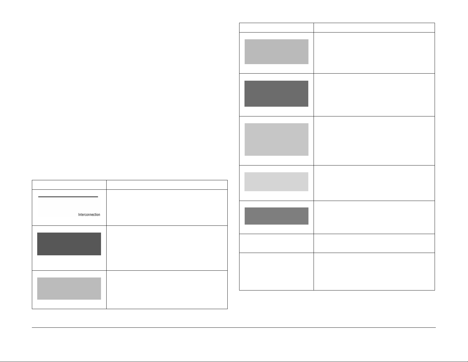
The symbols in the interconnection wiring diagrams are described below. Note that the
description of general symbols is omitted.
T able 1 Symbols Used in Wiring Diagrams
Symbol Description
Represents an interconnection between parts using wiring harness or wire, and indicates its signal name/contents. The arrow “>” or “<” on the line represents the
direction of signal flow.
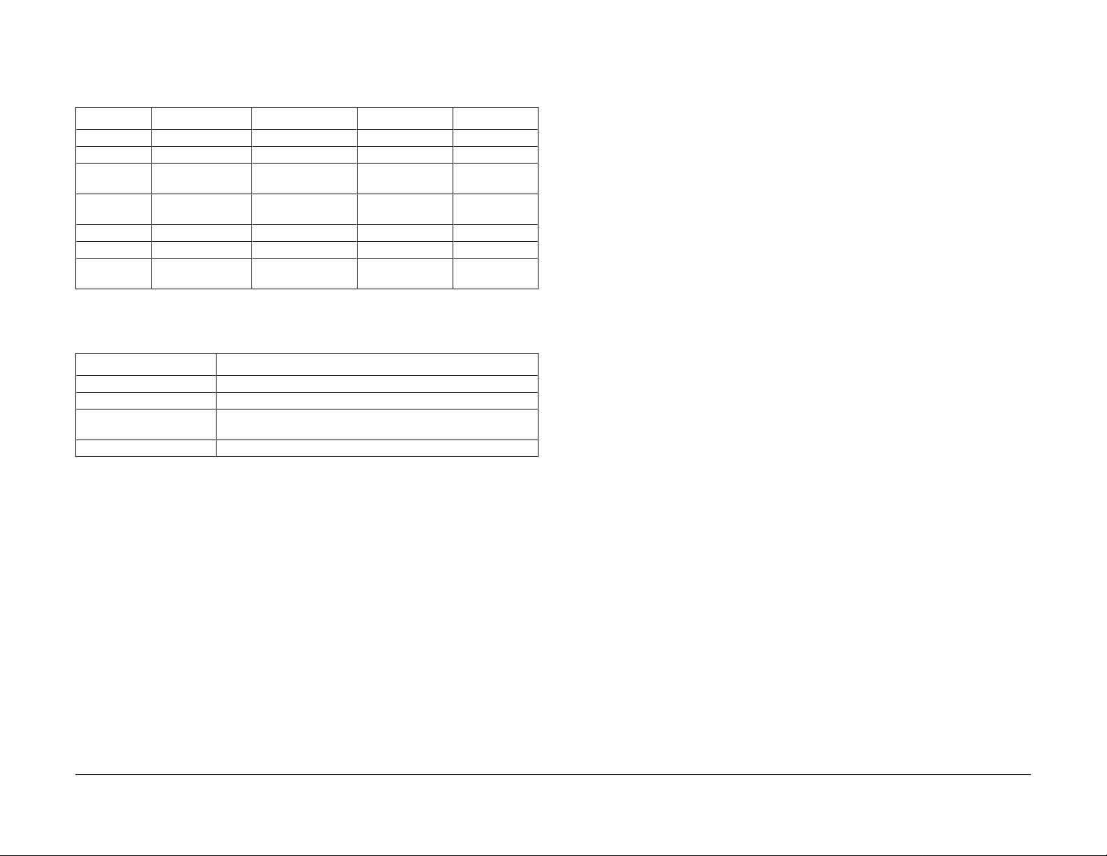
T ab le 1 Symbols Used in Wiring Diagrams
Symbol Description
Represents a function and a logical value (High (H) or
Low (L)) of a signal when the function is activated. The
voltage indicates a value when the signal is High. The
arrow indicates the direction of signal flow.
Figure 4 Function Activated
Represents a function and a logical value (High (H) or
Low (L)) of a signal when the function is in a detectable
state. The voltage indicates a value when the signal is
High. The arrow indicates the direction of signal flow.
Figure 5 Function Detectable
Represents a connection between lead wires.
Figure 6 Lead Wires Connection
Represents a connection between parts by tightening of
a screw.
Figure 7 Screw Connect ion
Represents a connection between “A” and “A.”
Figure 1 Interconnection
Represents an interconnection between parts using wiring harness or wire, which differs according to the specifications, and indicates its signal name/contents. The
arrow “>” or “<” on the line represents the direction of signal flow.
Figure 2 Interc onne c t ion Differ-
ence
Represents a connection between parts using a conductive member such as a plate spring, and indicates its signal name/contents. The arrow “>” or “<” on the line
represents the direction of signal flow.
Figure 3 Conductive Pa rts
Introduction
How to Use this Documentation
24 VDC The DC voltage indicates an approximate value mea-
March 2008
iv
Figure 8 Point Connection
sured when the negative side is connected to a signal
ground (SG).
Indicates a signal ground (SG).
Figure 9 Signal Gro und
Initial Issue
Phaser® 5500/5550 Printer
Page 6

T able 1 Symbols Used in Wiring Diagrams
Symbol Description
Indicates a frame ground (FG).
T ab le 1 Symbols Used in Wiring Diagrams
Symbol Description
Indicates a reference item associated with the section.
Figure 10 Frame Ground
RTN Indicates a return.
Represents a connector. The connector and PIN Nos.
are shown at the upper and lower parts respectively.“P,-”
indicates the plug side of the connector.“J,>” indicates
the jack side of the connector.
Figure 11 Plug and Jack
Represents a connection terminal with a plate spring on
the printed circuit board. The connector No. is indicated
inside the box.
Figure 12 Connection Terminal
Represents a connector directly connected to the printed
circuit board. The connector No. is indicated inside the
box.
Figure 13 PCB Connection
Represents a part.
“PL X.Y.Z” indicates the item “Z” of the plate (PL) “X.Y”
described in section 5 “Parts List”.
Figure 16 Reference Mark
Figure 14 Part
Figure 15 Functional Part
Initial Issue
Phaser® 5500/5550 Printer
Represents a functional part within a part, and indicates
the name of the functional part.
March 2008
v
Introduction
How to Use this Documentation
Page 7

Vo ltage Me asurem e nt and Specific ations
Measurements of DC voltage must be made with reference to the specified DC Common,
unless some other point is referenced in a diagnostic procedure. All measurements of AC voltage should be made with respect to the adjacent return or ACN wire.
T ab le 2 Voltage Measurement and Specifications
Voltage Specification
INPUT POWEW 220 V 198 VAC TO 242 VAC
INPUT POWER 100 V 90 VAC TO 135 VAC
INPUT POWER 120 V 90 VAC TO 135 VAC
+5 VDC +4.75 VDC TO +5.25 VDC
+24 VDC +23.37 VDC TO +27.06 VDC
Power Safety Precautions
Power Source
For 115 V A C printers, DO NO T apply more than 127 volts RMS between the supply conductors
or between either supply conductor and ground. For 230 VAC printers, DO NOT apply more
than 254 volts RMS between the supply conductors or between either supply conductor and
ground. Use only the specified power cord and connector. Only qualified service technician
should be using this Service Manual to perform the service.
Plug the three-wire power cord (with grounding prong) into a grounded AC outlet only. If necessary, contact a licensed electrician to install a properly grounded outlet. If the product loses its
ground connection, contact with conductive parts may cause an electrical shock. A protective
ground connection by way of the grounding conductor in the power cord is essential for safe
operation.
Logic Voltage Levels
Measurements of logic levels must be made with reference to the specified DC Common,
unless some other points is referenced in a diagnostic procedure.
Table 3 Log ic Levels
Voltage H/L Specification
+5 VDC H= +3.00 TO +5.25 VDC
L= 0.0 TO 0.8 VDC
+24 VDC H= +23.37 TO +27.06 VDC
L= 0.0 TO 0.8 VDC
DC Voltage Measuremen t in RAPs
The RAPs have been designed so that when it is required to use the Digital Multimeter (DMM)
to measure a DC voltage, the first Test Point (TP) listed is the location for the red (+) meter lead
and the second test point is the location for the black meter lead. For example, t he following
statement may be found in a RAP.
There is +5 VDC from TP7 to TP68.
In this example, the red meter lead would be placed on TP7 and the black meter lead on TP68.
There is -15 VDC from TP21 to TP33.
In this example, the red meter lead would be placed on TP21 and the black meter lead would
be placed on TP33.
If a second test point is not given, it is assumed that the black meter lead my be attached to the
printer frame.
Disconnecting Power
WARNING
Turning the power Off using the power switch does not completely de-energize the
printer. You must also disconnect the power cord from the printer’s AC inlet. Disconnect
the power cord by pulling the plug, not the cord.
It is also important that sufficient time is allowed for printer shutdown prior to unplugging the power c ord from the printer or p ower source. This can be determin e d by checking the Control Panel display, after turning the printer power Off, and waiting until the
LCD display shuts down.
Disconnect the power cord from the wall first, then the printer in these cases:
• if the power cord or plug is frayed or otherwise damaged,
• if any liquid or foreign material is spilled into the product,
• if the printer is exposed to any excess moisture,
• if the printer is dropped or damaged,
• if you suspect that the product needs servicing or repair,
• whenever you clean the product.
Introduction
How to Use this Documentation, P o wer Safety
March 2008
vi
Initial Issue
Phaser® 5500/5550 Printer
Page 8

Service Safety Summary
General Safety
The printer and recommended supplies have been designed and tested to meet strict safety
requirements. Attention to the following inform ation will ensure the continued safe operation of
the printer.
Operational Safety
The printer and supplies were designed and tested to meet strict safety requirements. These
include safety agency examination, approval, and compliance with established environmental
standards.
Pay attention to these safety guidelines to ensure the continued, safe operation of the printer.
Electrical Safety
• Use the Power Cord supplied with the printer.
• Plug the Power Cord directly into a properly grounded electrical outlet.
• Do not use a ground adapter plug to connect the printer to an electrical outlet that does
not have a ground connection terminal.
• Do not use an ex tension cord or power strip.
• Do not place the printer in an area where people might step on cord the power cord.
• Do not place objects on the power cord.
• Do not block the ventilation openings. These openings are provided to prevent overheating of the printer.
• Do not drop paper clips or staples into the printer.
WARNING
Avoid the potential of electrical shock by ensuring that the system is properly
grounded. Ele ctrical products may be hazardous if misused. The power cord is attached
to the printer as a plug-in device on the side of the printer. If it is necessary to disconnect all electrical power from the printer, d isconnect the power cord from the electrical
outlet.
WARNING
Do not remove the covers or guards that are fastened with screws unless you are
installing optional equipment and are specifically instructed to do s o. Power should be
Off when performing these installations. Disconnect the power cord when removing the
covers and guards for installing optional equipment. Except for user-installed options,
there are no parts that you can maintain or service behind these covers.
WARNING
The following are hazards to you r safety:
• Damaged or frayed Power Cord
• Liquid spilled into the printer
• Exposure to water or excessive moisture
If any of these conditions occur, perform the following:
1. Turn the Power Switch Off.
2. Disconnect the Power Cord from the electrical outlet.
3. Call an authorized service representative.
Maintenance Safety
• Do not attempt any maintenance procedure that is not specifically described in the documentation supplied with your printer.
• Do not use aerosol cleaners. The use of supplies that are not approved may cause poor
performance and could create a hazardous condition.
• Do not burn any consumables or routine maintenance items. For information on Xer ox
supplies recycling programs, go to www.xerox.com/gwa.
• Use the supplies specifically designed for your printer. The use of unsuitable materials
may cause poor performance and a possible safety hazard.
• Follow all warnings and instructions mar ked on, or supplied with, the printer, options, and
supplies.
Laser Safety
With specific regard to lasers, this printer complies wit h laser product performance standards
set by governmental, national, and international agencies and is certified as a Class 1 Laser
Product.
General Guidelines
• For qualified service personnel only: Refer also the preceding Power Safety Precautions.
• Avoid servicing alone: Do not perform internal service or adjustment of this product unless
another person capable of rendering first aid or resuscitation is present.
• Use care when servicing with power: Dangerous voltages may exist at several points in
this product. To avoid personal injury, do not touch exposed connections and components
while power is On. Disconnect power before removing the power supply shield supply
shield of replacing components.
• Do not wear jewelry: Remove j ewel ry prior to servicing. Rings, necklaces and other metallic objects could come into contact with dangerous voltages and currents.
Warning Labels
Read and obey all posted warning labels. Throughout the printer, warning labels are displayed
on potentially dangerous components. As you service the printer, check to make certain that all
warning labels remain in place.
Safety Interlocks
Make sure all covers are in place and all Interlock Switches are functioning correctly after you
have completed a printer service call. If you bypass an Interlock Switch during a service call,
use extreme caution when working on or around the printer.
Class 1 Laser Product
The Phaser 5500/5550 Printer is certified to comply with Laser Produc t Performance Standards set by the U.S. Department of Health and Human Services as a Class 1 Laser Product.
This means that this product does not emit hazardous laser radiation; which is possible only
because the laser beam is totally enclosed during all modes of customer operation. When servicing the printer or laser unit, follow the procedures specified in this manual and there will be
no hazards from the laser.
Initial Issue
Phaser® 5500/5550 Printer
March 2008
vii
Introduction
Service Safety Summary
Page 9

Servicing Electrical Components
WARNING
Do not touch any electrical component unless you are instructed to do so by a service
procedure.
Figure 1 Electrical Components Warning
Before starting any service procedure, switch the printer power Off and unplug the power cord
f
rom the wall outlet. If you must service the printer with power app lied, be aware of the poten-
tial for electrical shock.
Servicing Mechanical Components
WARNING
Do not try to manually rotate or stop the drive assemblies while any printer motor is running.
Electrostatic Discharge Pr ecautions
Some semiconductor components, and the respective sub-assemblies that contains them, are
vulnerable to damage by ESD. These co mponents include Integrated Circuits (ICs), LargeScale Integrated Circuits (LSIs), field-effect transistors and other semiconductor chip components. The following techniques will reduce the occurrence of component damage caused by
static electricity.
Be sure the power is Off to the chassis or circuit board, and obser ve all other safety precautions.
• Immediately before handling any semiconductor components assemblies, drain the electrostatic charge from your body. This can be accomplished by touching an earth ground
source or by wearing a wrist strap device connected to an earth ground source. Wear ing
a wrist strap will also prevent accumulation of additional bodily static charges. Be sure to
remove the wrist strap before applying power to the unit under test to avoid potential
shock.
• After removing a static sensitivity assembly from its anti-static bag, place it on a grounded
conductive surface. If the anti-static bag is conductive, you may ground the bag and use
as a conductive surface.
• Do not use freon-propelled chemicals These can generate electrical charges sufficient to
damage some devices.
• Do not remove a replacement component or electrical sub-assembly from its protective
package until you are ready to install it.
• Immediately before removing the protective material from the leads of a replacement
device, touch the protective material to the chassis or circuit assembly into which the
device will be installed.
• Minimize body motions when handling unpacked replacement device. Motion such as
your clothes brushing together, or lifting a foot from a carpeted floor can generate enough
static electricity to damage an electro-statically sensitive device.
• Use tools specifically designed to remove or install IC’s and EPROM’s to avoid bending
pins.
• Pay attention to the direction of parts when mounting or inser ting them on the PCBs.
Figure 2 Mechanical Components Warning
When servicing mechanical components within the printer, manually rotate the Drive Assemblies, Rollers, and Gears.
Servicing Fuser Components
WARNING
This printer uses heat to fuse the toner image to the media. Th e Fuser is ver y ho t. Turn
the printer power Off and wait at least 5 mi nutes for the Fu ser to co o l before attempting
to service the Fuser or adjacent components.
Introduction
March 2008
Service Safety Summary, Electrostatic Discharge
viii
Initial Issue
Phaser® 5500/5550 Printer
Page 10

Electr ostatic Discharge Field Service Kit
The purpose of the Electrostatic Discharge (ESD) Program is to preserve the inherent reliability
and quality of electronic components that are handled by the Field Service Personnel. This
program is being implemented now as a direct result of advances in microcircuitry tec hnology,
as well as a new acknowledgement of the magnitude of the ESD problem in the electronics
industry today.
This program will reduce Field Service costs that are charged to Printed Wiring Board (PWB)
failures. Ninety percent of all PWB failures that are ESD related do not occur immediately.
Using the ESD Field Service Kit will eliminate these delayed failures and intermittent problems
caused by ESD. This will improve product reliability and reduce callbacks.
The ESD Field Service Kit should be used whenever PWBs or ESD sensitive components are
being handled. This includes activities like replacing or reseating circuit boards or connectors.
The kit should also be used in order to prevent additional damage when the circuit boards are
returned for repair.
The instructions for using the ESD Field Service Kit can be found in ESD Field Service Kit
Usage in the General Procedures section of the Service Manual.
Service Terms
Manual Terms
Various terms are used throughout this manual to either provide additional information on a
specific topic or to warn of possible danger present during a procedure or action. Be aware of
all symbols and terms when they are used, and always read NOTE, CA UTION, and WARNING
statements.
• Consumables: Ink, toner, or print car tridge that is consumed. Customer is expected to
replace once consumed.
• Routine Maintenance Item: Supply item or kit that has a finite life. Customer is expected
to replace at end-of-life.
• Accessory: A single component or assembly that may be added to a printer ; however, it
is NOT an option to the product.
Common Acronyms
• FRU: Field Replaceable Unit
• PL: Corresponds to the FRU Parts List.
• CRU: Customer Replaceable Unit
• ESD: Electrostatic Discharge
Initial Issue
Phaser® 5500/5550 Printer
March 2008
ix
Introduction
Electrostatic Discharge Precautions, Service
Page 11

Symbology and Nomenclature
The following reference symbols are used throughout the documentation.
Warnings, Cautions, and Notes
Various terms are used throughout this manual to either provide additional information on a
specific topic or to warn of possible danger present during a procedure or action. Be aware of
all symbols and terms when they are used, and always read Note, Caution, and Warning statements.
Warnings, Cautions, and Notes will be found throughout the Service Manual. The words
WARNING or CAUTION m ay be listed on an illustration when the specific component associated with the potential hazard is pointed out; however, the m essage of the WARNING or CAUTION is always located in the text. The WARNING and CAUTION definitions are as follows:
WARNING
A warning indicates an operating or maintenance procedure, practice or condition that,
if not strictly observed, results in injury or loss of life.
CAUTION
A caution indicates an operating or maintenance procedure, practice or condition that, if not
strictly observed, results in damage to, or destruction of, equipment.
NOTE: A note indicates an operating or maintenance procedure, practice or condition that is
necessary to efficiently accomplish a t ask. A note can provide additional information related to
a specific subject or add a comment on the results achieved through a previous action.
Common Warnings Machine Safety Symbols
The following common warnings are used throughout the documentation and the s afety icons
are displayed on the machine. Additional specific warnings are included for the listed sections.
Common Warnings
WARNING
To avoid personal injury or shock, do not perform repair or adjustment activities with
the power switch On or electrical power applied to the machine.
DANGER: Afin d'éviter des blessures ou des chocs électriques, ne pas effectuer des
activités de maintenance ou de réglage avec l'équipement sur Marche ou avec le cordon
d'alimentation branché.
WARNING
A Warning is used whenever an operating or maintenance pro cedure, a practice, conditioning, or statement, if not strictly observed, could result in personal injury.
DANGER: Une note DANGER est utilisée à chaque fois qu’une procédure de maintenance ou qu’une manipulation présente un risque de blessure si elle n’a pas été strictement observée.
WARNING
Personal injury may result fr om grasping hot areas of the Fuser Uni t. I f a hot Fu ser must
be removed, grasp the Fuser by the black p lastic frame comp onent.
DANGER: Des blessures peuvent résulter si les zones chaudes du module de four sont
touchées. Si un module de four chaud doit être enlevé, le saisir par l'élément en plastique noir du bâti.
WARNING
This machine contains an invisible laser. There is no visual indication that the laser
beam is present. During servicing, the machine is a Class 3B p roduct, because of the
invisible laser beam could cause eye damage if looked at directly. Service procedures
must be followed exactly as written without change. The service rep resentative must
observe the established local laser safety precautions when servicing the m achine. Do
not place tools with a reflective surface in the area of the ROS opening. Do not look in
the area of the ROS window if the power is On and the laser is energized.
DANGER: L'équipement contient un faisceau laser invisible et aucune indication visible
signale la présence du faisceau laser. De ce fait le produit est classé 3B pour tout ce qu i
concerne la maintenance. L'exposition directe des yeux au faisceau laser peut entraîner
des lésions visuelles. Les procédures de maintenance doivent être réalisées sans
aucun changement comme indiqué dans la documentation. Le représentant Xerox lors
d'interventions sur l'équipement doit respecter les consignes de sécurité locales co ncernant les faisceaux laser. Ne pas placer d'objet réfléchissant dans la zone du ROS
quand il est ouvert. Ne pas regarder dans la zone du ROS lorsque la machine est sous
tension et que le laser est en fonctionnement.
Introduction
Symbology and Nomenclature
March 2008
x
Initial Issue
Phaser® 5500/5550 Printer
Page 12

WARNING
The following symbol and statement appear on a label in the machine. The symbol by
itself, or the symbol and the statement may also appear in the Service Manual and in the
Training program. When this symbol appears, the service representative is warned that
conditions exist that could result in exposure to the laser beam.
DANGER: Les symboles et instructions suivants sont indiqués sur des étiquettes dans
la machine et sont identifiés dans la documentation technique et dans le manuel de formation. Quand ces symboles s'affichent le représentant Xerox est prévenu des risques
encourus concernant une exposition au rayon laser.
WARNING
Do not try to bypass any laser interlocks fo r any reason. Permanent eye damage could
result if the laser is accidentally directed into your eyes.
DANGER: Ne pas essayer de shunter les contacts laser pour quelques raisons que ce
soit. Si le faisceau laser est dirigé accidentellement vers les yeux il peut en résulter des
lésions oculaires permanentes.
WARNING
HIGH VOLTAGE!
DANGER: HAU TE TENSION!
Exercise with care when making the voltage check in the following steps.
DANGER: Soyez extrêmement vigilant lorsque vous effectuez les tests de tension au
cours des étapes qui suivent.
Machine Safety Icons
Danger invisible laser radiation when open. Avoid direct exposure to beam.
Figure 3 Protective Ground (earth) Symbol
These symbols indicate hot surface on or in the printer. Use caution to avoid personal injury.
Figure 4 Hot Surface On Printer Symbol
Figure 5 Hot Surface Symbol
The surface is hot while the printer is running. After turning the power Off, wait 30 minutes.
Figure 1 Laser Hazard Symbol
This symbol indicates Danger High Voltage.
Figure 2 Danger High Voltage Symbol
Protective ground (earth) symbol.
Initial Issue
Phaser® 5500/5550 Printer
It may take 30 minutes fo r the Fuser to cool down.
March 2008
xi
Figure 6 Caution 30 Minutes Symbol
Figure 7 30 Minutes for Fuser to Cool Down Symbol
Introduction
Symbology and Nomenclature
Page 13

Avoid pinching fingers in the printer. Use caution to avoid personal injury.
Figure 8 Pinching Fingers Caution Symbol
Do not burn the Printer Cartridge.
Use caution (or draws attention to a particular component ). Refer to the documentation for
inf
ormation.
Figure 9 Use Caution Symbol
Do not touch the item.
Figure 10 Do Not Touch Item Symbol
Do not expose the item to sunlight.
Figure 13 Do Not Burn Print Cartridge Symbol
Do not expose the Print Cartridge to sunlight.
Figure 14 Do Not Expose Print Cartridge to Sunlight Symbol
Figure 11 Do Not Expose Item to Sunlight Symbol
Do not expose the item to light.
Figure 12 Do Not Expose Item to Sunlight Symbol
Introduction
Symbology and Nomenclature
March 2008
xii
Initial Issue
Phaser® 5500/5550 Printer
Page 14

Regulatory Specifications
Xerox has tested this product to electromagnetic emission and immunity standards. These
standards. These standards are designed to mitigate interference caused or received by this
product in a typical office environment.
United States (FCC Regulations)
This equipment has been tested and found to comply with the limits for a Class A digital device
pursuant to Part 15 of the FCC Rules. These limits are designed to provide reasonable protection against harmful interference in a commercial installation. This equipment generates, uses,
and can radiate radio frequency energy. If it is not installed and used in accordance with these
instructions, it may cause harmful interference to radio communications. Operation of Class A
equipment in a residential area is likely to cause harmf ul interference in which case the user
will be required to correct the interference at his/her own expense. There is no guarantee that
interference will not occur in a particular installation. If this equipment does cause harmful
interference to radio or television reception, which can be determined by turning the equipment
Off and On, the user is encouraged to try to correct the interference by one or more of the following measures:
• Reorient or relocate the receiver (device being interfered with).
• Increase the separation between the printer and the receiver.
• Connect the equipment into an outlet on a circuit different from that which the receiver is
connected.
• Consult the dealer or an exper ienced radio/television technician for help.
Any changes or modifications not expressly approved by Xerox could void the user’s authority
to operate the equipment. To ensure compliance with Part 15 of the FCC rules, use shielded
interface cables.
Canada (Regulations)
This Class A digital apparatus complies with Canada ICES-003.
European Union
The CE marking applied to this product s ymbolizes Xerox’ declaration of conformity with the
following applicable Directiv es of the European Union as of the dates indicated:
Figure 1 CE Marking
12 December 2006: Low Voltage Directive 2006/95/EC
15 December 2004: Electromagnetic Compatibility Directive 2004/108/EC
9 March 1999: Radio & Telecommunications Terminal Equipment Directive 1999/5/EC
This product, if used properly in accordance with the user’s instructions, is neither dangerous
for the consumer nor the environment.
To ensure compliance with European Union regulations, use shielded interface cables.
A signed copy of the Declaration of Conformity for this product can be obtained from Xerox.
Cet appareil numérique de la classe A est conforme à la norme NMB-003 du Canada.
Initial Issue
Phaser® 5500/5550 Printer
March 2008
xiii
Introduction
Regulatory Specifications
Page 15

Phaser 5500/5550 Printer Overview
The Phaser 5500/5550 printer combines a dual-pass, monochrome laser print engine with an
image processor supporting Adobe’s PostScript 3 description language. The PCL5e, PCL6
and Oak PCL 5.0 printer languages are als o supported. Print speed is 50 pages per minute at
either 600 x 600 or T rue 1200 x 1200 dpi in 1-sided or 2-sided modes. The printer features a bidirectional parallel interface and a USB port. The Phase r 5500/5550 printer provides a 100sheet Tray 1/MPT from which specialty media, card stock, larger format paper, and envelopes
are fed. Tray 1 also supports manual feeding. Two additional trays, Tray 2 and 3, each provide
500 sheets of capacity. The Standard Output Tray holds 500 sheets face down.
Phaser 5500/5550 printer options add memor y, paper capacity and f unctionality. For models
not originally equipped, an internal Hard Drive is available fo r font storage, storing print files,
job collation, proof print and secure pr int support. A selection of RAM memor y upgrades are
available to raise th e installed quantity to the 1 GB maximum. A 1000-Sheet Feeder is available with two, 500-sheet universal media trays (Trays 4 and 5). A 2000-Sheet Feeder (Tray 6)
brings the maximum input capacity to 4,100 sheets. An Envelope Tray, replacing Tray 2, is
available to feed envelopes. On the output side, a 3,500-sheet, high-capacity stapler/punch/
stacker is available rais ing the output total to 4000 sheets. A Configuration Card op tion adds
Ethernet 10/100/Gigabit baseTx networking to base models.
Figure 1 Phaser 5500/5550 Printer
Phaser 5500/5550 Differences
New for the 5550 model is a revised Image Processor Board that increases RAM memory
capacity, processor speed, and is redesigned to permit customer replacement. Added to t he
Rear Panel is an Engine Test Print button that bypasses Image Processor Board logic to
quickly isolate some printer malfunctions. Access to error r eports is improved with the addition
of a Printer Status page that lists the last 30 errors recorded.
Phaser 5500/5550 Printer Conf igurations
Table 1 lists Phaser 5500/5550 printer configurations.
NOTE: For the 5550 model, base memory is increased from 128 MB to 256MB, with a new
maximum of 1 GB. The DX model has been dropped for the 5550.
Tabl e 1 Phaser 5500/5550 Configurations
Printer Configurations 5500/5550
Features
Maximum Print
Speed (Letter-size
Paper)
Memory 128/256 MB 128/256 MB 128/256 MB 128/256 MB 128 MB
PostScript Fonts 137 137 137 137 137
Oak PCL 5.0 Yes Yes Yes Yes Yes
PCL5e/PCL6 Yes Yes Yes Yes Yes
Job Pipelining Yes Yes Yes Yes Yes
PDF Direct Print Yes Yes Yes Yes Yes
Resolutions (dpi) 600 or True
USB, Parallel Yes Yes Yes Yes Yes
Ethernet Capabilities Optional Standard Standard Standard Standard
1000-Sheet Feeder Optional Optional Optional Standard Standard
Automatic 2-Sided
Printing (Requires
Duplex Unit)
Hard Drive Optional Optional Optional Optional Standard
Job Collation (Hard
Drive Required)
Proof Print, Personal
Print, Secure Print,
Saved Jobs (Hard
Drive Required)
2,000-Sheet Feeder
(Requires 1000Sheet Feeder)
3,500-Sheet Feeder
(Requires 1000Sheet Feeder)
B N DN DT DX (5500)
50 ppm 50 ppm 50 ppm 50 ppm 50 ppm
1200 dpi
Optional Optional Standard Standard Standard
Optional Optional O ptional Optional Standard
Optional Optional O ptional Optional Standard
Optional Optional O ptional Optional Standard
Optional Optional O ptional Optional Standard
600 or True
1200 dpi
600 or True
1200 dpi
600 or True
1200 dpi
600 or True
1200 dpi
The adoption of current controller functionality puts 5550 behavior into alignment with other
recently released products. The 5550 offers the same input and output options as the 5500.
Supplies and consumables are compatible between models.
Introduction
March 2008
Phaser 5500/5550 Printer Overview, Phaser 5500/
xiv
Initial Issue
Phaser® 5500/5550 Printer
Page 16

Parts of the Printer
Front View
1. Standard Output Tray
2. Front Door
3. Trays 2 and 3
4. Optional Duplex Unit
5. Tray 1/MPT
6. 2000-Sheet Feeder (Tray 6)
7. 1000-Sheet Feeder (Trays 4 & 5)
8. Finisher
9. Stacker Lower Tray
10. Stacker Upper Tray
Rear View
1. Parallel Connection
2. Test Print Button
3. USB Connection
4. Ethernet Connection
5. Mode Select Port
6. Serial Debug Port
7. Configuration Card
8. Ground Fault Interrupt Reset
9. Printer Power Connection
10. Finisher Connection
11. 1000-Sheet Feeder Connect ion
12. Duplex Unit Connector
Initial Issue
Phaser® 5500/5550 Printer
Figure 1 Front Vi ew
March 2008
xv
Figure 2 Rear View
Introduction
Parts of the Printer
Page 17

Control Panel
The Control Panel consists of one tricolor LED, a display, and six functional buttons. Listed
below are the functions of each Control Panel control and indicator.
1. LED
2. Control Panel Display
3. Toner Gauge
4. Cancel button
5. Back button
6. Up Arrow button - scrolls up the menu system
7. Down Arrow bu tton - scrolls down the menu system
8. OK (select) button
9. Information button - for additional explanation or help
Printer Options
Phaser 5500/5550 printer options include:
• Hard Drive
• Additional RAM and NVRAM
•Exit 2
• 1000-Sheet Feeder (Trays 4 & 5)
• Duplex Unit
• 3,500-Sheet Stacker (with offset)
• 3,500-Sheet Finisher (with hole punch, staple, offset)
• 2,000-Sheet Feeder (Tray 6)
• Envelope Tray (replaces Tray 2)
Hard Drive
A hard drive is available to enable the Job Collat ion, Saved Jobs, Proof, Personal, and Secure
Print options. The hard drive installs on the Image Processor Board with stand-offs and connects to the board with a single data/power connector.
Additional Memory
Options provide additional RAM in 256 MB and 512 MB increments. Also available is 32 MB of
Flash Memory for fonts, forms, and macros. Both RAM and NVRAM options install to the
Image Processing board. The Startup Page and Configuration Page list the amount of installed
RAM. Refer to Memory Specifications.
Exit 2
Exit 2 is required when either the Duplex Unit or Stacker/Finisher is installed. When used in
conjunction with the Duplex Unit, Exit 2 performs as a paper inverter. With the Stacker/Fi nisher,
Exit 2 serves as the replacement face-down exit to the top tray. Exit 2 mounts directly above
Exit 1 with spring loaded latches and guide pins.
Figure 3 Control Panel
LED States
Table 1 LED States
LED State Print State
Green Ready to print
Flashing Yellow Warning (but can still print)
Flashing Green In Power Saver mode or busy (receiving or processing data)
Flashing Red Error; cannot print
Introduction
Parts of the Printer, Printer Options
Networking
A Configuration Card is used to enable or disable networking capabilities. This option provides
a replacement card to enable Ethernet on the base model (Phaser 5500/5550B printer).
March 2008
xvi
Initial Issue
Phaser® 5500/5550 Printer
Page 18

1000-Sheet Feeder
The 1000-Sheet Feeder forms a base for the printer and adds two, 500-sheet trays (Tray 4 and
Tray 5). Control signals reach the sheet feeder by a single connection. The sheet feeder is
secured to the print engine with two screws located under the front edge of Tr ay 3.
Figure 1 1000-Sheet Feeder
Duplex Unit
The Duplex Unit adds two-sided printing. The Duplex Unit attaches to the left side above Tray
1 using two twist locks. Installation of the Duplex Unit requires that the Exit 2 Module also be
added to provide reverse drive. Electrical connection to the printer is made by an interface
cable.
Stacker / Finisher
The Stacker/Finisher increases the output capacity of the printer by 3,500 sheets. Printer output is directed to the Stacker/Finisher by w ay of Exit 1 and the Horizontal T ransport. With Exit 2
installed, the top surface of the Horizontal Transport serves as the top tray and paper output
capacity remains at 500 sheets. Depending on the level of Stacker/Finisher options and job
specifications, as paper enters the Stacker/Finisher it is punched, stapled, offset and stacked.
Control signals reach the Stacker/Finisher through a single connector. Power is supplied from
the printer’s AC Accessory Panel.
Initial Issue
Phaser® 5500/5550 Printer
Figure 2 Duplex Unit
March 2008
xvii
Figure 3 Stacker / Finisher
Introduction
Printer Options
Page 19

2000-Sheet Feeder
The 2000-Sheet Feeder (Tray 6) nearly doubles the input capacity of the printer. The feeder
attaches to the left side of printers equipped with the 1000-Sheet Feeder option just belo w Tray
1/MPT using the supplied docking bracket. Electrical connection to the printer is made by an
interface cable.
Figure 4 2000-Sheet Feeder
Envelope Tray
The Envelope Tray replaces Tray 2 to feed envelopes.
Consumables and Routine Maintenance Items
Figure 1 Consumables and Routine Maintenance Items
Supply Life Counters
Counters track the usage of the consumables and routine maintenance items and store the
values in NVRAM. Access the current status of these counters from the Supplies Info menu. In
addition to the counters, a T oner Gauge is provided on the Control Panel that approximates the
Toner Car tridge counter value. As counters near their minimums, warning messages appear
on the Control Panel.
Figure 5 Envelope Tray
CAUTION
T
o avoid damage to the Enveloper Tray, insert in the Tray 2 position only.
Introduction
Printer Options, Consumables and Routine Mainte-
Print life ratings are based on 5% average coverage and an average job length of 6 pages.
Consumables Print Life (N umber of Images)
Toner Cart r idge 30,000 (5500) 35,000 (5550)
Routine Maintenance Items
Fuser 300,000
Drum Cartridge Up to 60,000 dependent on job size
Maintenance Kit (consists of Fuser,
Transfer Roller and 15 Feed Rollers)
March 2008
xviii
Table 1 Consumables and Routine Maintenance Items Life Expectancy
300,000
Initial Issue
Phaser® 5500/5550 Printer
Page 20
Printer Specifications
Physical Dimensions
Table 1 Physical Dimensions
Device Height Width Depth Weight
Print Engine 498 mm (19.6 in.) 640 mm (25.2 in.) 525 mm (20.7 in.) 41 kg 90 lbs.)
Duplex Unit 211 mm (8.3 in.) 64 mm (2.52 in.) 458 mm (18.0 in.) 1.8 kg (4 lbs.)
1000-Sheet
Feeder
Stacker / Fin-
isher
Exit 2 142 mm (5.6 in.) 130 mm (5.1 in.) 460 mm (18.1 in.) 2 kg (4.4 lbs.)
Envelope Tray 76 mm (3.0 in.) 538 mm (21.2 in.) 521 mm (20.5 in.) 3.2 kg (7 lbs.)
2000-Sheet
Feeder
Memory Specifications
Characteristic Specification
Minimum RAM 128 MB (5500), 256 MB (5550)
Maximum RAM 512 MB (5500), 1 GB (5550)
Supported RAM SO-DIMM 144-pin module of 128, 256, or 512 MB. All combina-
NVRAM Single chip either PPROM or StrataFlash 16 or 32 MB
280 mm (11.0 in.) 540 mm (21.2 in.) 520 mm (21.1 in.) 23 kg (50 lbs.)
1050 mm (41.3 in.) 740 mm (29.1 in.) 650 mm (25.6 in.) 49 kg (108 lbs.)
363 mm (14.3 in.) 385.5 mm (15.1 in.) 600 mm (23.6 in.) 50 kg (110 lbs.)
T ab le 2 Memory Specifications
tions are allowed for configurations to the maximum allowable.
Initial Issue
Phaser® 5500/5550 Printer
March 2008
xix
Introduction
Printer Specifications
Page 21

Functional Specifications
Environmental Specifications
Table 3 Functional Specifications
Characteristic Specification
Printing Process Recording System: Electrophotography (roller charging, mag-
Resolution / Addressability 600/ True 1200 dpi
Print-Quality Modes Two choices:
Continuous Operating
Printing Speed
Warm-Up Time:
Sleep Mode
Stand By
netic dual component toner and DRUM Cartridge)
Exposure System: Semiconductor laser beam scanning
Transfer System: Roller transfer system
Fusing System: Thermal fixing using a heat roller
• 600 x 600 dpi
• True 1200 x 1200 dpi
50 pages per minute for plain Letter paper, simplex or duplex
50 pages per minute for A4 paper, simplex or duplex
45 sec.
6 sec.
Electrical Specifications
Table 4 Electrical Specifications
Characteristic Specification
Primary Line Voltages 12 0 VAC nominal, min. 99 V, max. 135 V
220/240 VAC nominal, min. 198 V, max. 254 V
Primary Line Voltage Frequency Range
Input Current:
Operating
Rush
Power Consumption:
Operating (5500/5550DX)
Sleep Mode
BTU’s at 120V:
BTU’s at 240V:
50/60 Hz +/-3 Hz
12 A max. @ 120 V
8 A max. @ 240 V
100 A max.
1150 W max. @ 120 V, 1300 W max. @ 240 V
10 W max @ 120/240 V
Operating 3924
Power Saver 34
Operating 4436
Power Saver 34
Table 5 Environmental Specifications
Characteristic Specification
Temperature
Operating
Transport a tion
Humidity (%RH)
Operating
Transport a tion
Altitude
Operating
Transport ation*
Print Engine Acoustic Noise LWA(B)
Standby
Printing
Options Acoustic Noise LWA(B)
Idle
Printing
* Air transportation in pressurized cargo space
5 to 32° C (41 to 95° F)
-20 to 40° C (-4 to 104° F)
15 to 85
5 to 85
0 to 2,500 meters (8,200 feet)
0 to 15,000 meters (49,200 feet)
Engine Only
4.0 B
7.1 B
Engine Only
4.00 B
6.80 B
Bystander Position
22 db
54 db
With Options
---
7.00 B
Tray and Media Specifications
Table 6 Tray Specifications
Characteristic Trays Specification
Printable Area All Within 4 mm of paper edge guaranteed. Edge-
Supported Envelopes
Supported
Media Weights
Tray Capacity Tray 1
Tray 1 or Tray 2 (with
Envelope Tray installed)
Tray 1,3,4,5,6
Tray 2
Duplex
Tray 2
Tray 3
Tray 4
Tray 5
Tray 6
Top (face-down)
Stacker/Finisher
to-edge printing supported.
COM-10 (4.1 x 9.5 in.)
Monarch (3.8 x 7.5 in.)
DL (110 x 220 mm)
C5 (162 x 229 mm)
2
60-216 g/m
60-105 g/m
60-163 g/m
100 Sheets / 15 envelopes
500 Sheets or to fill line with Envelope Tray
500 Sheets
500 Sheets
500 Sheets
2000 Sheets
500 Sheets
3000 elevator, 500 in top tray
Based on 75 g/m
Capacity is reduced for heavier/thicker stock.
(16 lb. bond to 133 lb. card stock)
2
(16 to 28 lb. bond)
2
2
(20 lb. letter-size) paper.
Introduction
Printer Specifications
March 2008
xx
Initial Issue
Phaser® 5500/5550 Printer
Page 22

Phaser 5500/5550 Printer Menu Map
Initial Issue
Phaser® 5500/5550 Printer
Figure 1 Menu Map (page 1)
March 2008
xxi
Figure 2 Menu Map (page 2)
Introduction
Phaser 5500/5550 Printer Menu Map
Page 23

Service Call Procedures.................................................................................................. 1-3
Servicing Instruction s.................................................................... ......................... ......... 1-4
1 Service Call Procedures
Initial Issue
Phaser® 5500/5550 Printer
March 2008
1-1
Service Call Procedures
Page 24

Service Call Procedures
Perform the following proce dures whenever you check, service, or repair a printer. Cleaning
the printer, as outlined in the following steps, assures proper operation of the printer and
reduces the probability of having to service the printer in the future.
The frequency of use and the type of paper a customer prints on determines how critical and
how often cleaning is necessary.
Technician’s Tool Kit
Table 1 lists rcommon tools used to service this and other similar products.
Table 1 Service Tools
Description Detail Part Number
Phillips Drivers #2 and #1 5.0 x 75mm, 3.0 x 75mm, 6.0 x
Screw Driver (-) 3 x 50 600T40205
Screw Driver (+) 6 x 100 600T1989
Screw Driver (+) NO. 1 499T356
Screw Driver (=) 100MM 499T355
Spanner and Wrench 5.5 x 5.5 600T40501
Spanner and Wrench 7 x 7 600T40502
Hex Key Set 600T02002
Box Driver 5.5 mm 600T1988
Box Driver 1/4 inch
Side Cutting Nipper 600T40903
Round Nose Pliers 600T40901
Lubricant/Grease Reolube 070E00890
Cleaners Multipurpose surface cleaner and Alcohol
ESD Strap
Nut Driver 5.5mm (magnetic) 600T2123
Serial Adaptor Cable 600T80374
Network Cross-over cable Tech
Multimeter Volts, Ohms, Current 600T2020
Interlock Cheater 600T91616
Silver Scale 150MM 600T41503
CE Tool Case 600T1901
Magnetic Screw Pick-up 600T41911
Scribe Tool 600T41913
Eye Loop 600T42008
Flashlight 600T1824
Brush 600T41901
Test Lead Red 600T9583
Test Lead Black 600T2030
IC Chip Puller
100mm
Cleaning
CAUTION
Never apply alcohol to any parts in the printer. If you remove the Drum Cartridge, place it in a
light protective bag.
NOTE: Never use a damp cloth to clean up toner.
1. Record number of sheets printed.
2. Print several sheets of paper to check for problems or def ects. Print to all output trays and
staple or punch if Finisher is installed.
3. Print the fault history. Diagnose and repair to correct listed faults.
4. Turn Off the printer and disconnect the Power Cord.
5. Remove the I/P Board and Upper Rear covers and clean the Fuser Fan with a brush or
dry cloth to remove excess dust and toner.
6. Remove any debris or foreign objects from the Transfer Roller, Fuser, Laser Assembly,
and paper path.
7. Vacuum out any loose toner with a Type II toner vacuum only.
8. Remove and clean all paper trays.
9. Clean feed rollers with a lint-free cloth lightly dampened with water.
10. Inspect the interior of the printer for damaged wires, loose connections, toner leakage,
and damaged or obviously worn parts.
11. If the Drum or Toner Cartridges appear damaged, replace with a new one.
Initial Issue
Phaser® 5500/5550 Printer
March 2008
1-3
Service Call Procedures
Service Call Procedures
Page 25

Servicing Instructions
These instructions are an overview of the Steps a service technician s hould take, using this
manual, to service the print engine and options. If you choose not to use these Steps, it is recommended that you start at the appropriate troubleshooting procedure and proceed from
there. When servicing the printer, always follow the safety measures detailed in Service Safety
Summary in Introduction section.
Tabl e 1 Servicin g Instructions
Description
Step 1: Identify the Problem
• Verify the reported problem does not exist.
• Check for any error codes and write them down.
• Print normal customer prints and service test prints.
• Make note of any print-quality problems in the test prints.
• Make note of any mechanical or electrical abnormalities present.
• Make note of any unusual noise or smell coming from the printer.
• Print a Service Usage Profile, if the printer is able to print.
• View the Engine Error and Jam Histories under the Service Tools menu.
• Verify the AC input from the wall outlet is within specifications.
Step 2: Inspect and Clean the Printer
• Follow the Cleaning instructions in section 1, Service Call Procedures.
• Verify that the power cord is in serviceable condition.
• Restart the printer to check if the error reoccurs.
Step 3: Find the Cause of the Problem
• Use the troubleshooting procedures to find the root cause of the problem.
• Use Service Diagnostics to check the printer and optional components.
• Use the Wiring Diagrams and Plug/Jack Locator to locate test points.
• Take voltage readings as instructed in the appropriate troubleshooting procedure.
Step 4: Correct the Problem
• Use the Parts List to locate a part number.
• Use the FRU Disassembly procedures to replace the part.
Step 5: Final Checkout
• Test the printer to verify the problem is corrected and no new problems arose.
Service Call Procedures
Servicing Instructions
March 2008
1-4
Initial Issue
Phaser® 5500/5550 Printer
Page 26

Overview......................................................................................................................... 2-3
Messages, Codes, and Procedures
Entry Level Fault Isolation Procedure............................................................................. 2-9
Main Motor Failure.......................................................................................................... 2-9
Drum Motor Failure - U1-4 Drum Motor Failure.............................................................. 2-10
Laser Unit Failure - U3-3 Laser Power............................................................................ 2-10
Laser Motor Failure - U3-5 Polygon Motor Rotation ....................................................... 2-11
Fuser Failure - U 4-1 On Time ......................................................................................... 2-11
Fuser Failure - U4-n Over Heat / Thermistor .................................................................. 2-12
Fuser Failure - U4-7 Cold Sagging ................................................................................. 2-13
Fan Failure - U4-9 Fan Defect.............. ......................... .......................... ....................... 2-14
Toner Motor Failure - U5-1 Motor Rot at io n.................... .......................... ....................... 2-14
Fan Failure - U5-9 Fan Failure.............. ......................... .......................... ....................... 2-15
Engine Control Board Failure - U6-2, 3, 4, 5, 6, 7 ........................................................... 2-15
Paper Size Jam - E1-1 Regi Area Jam ........................................................................... 2-16
Jam at A - E1-2 Regi Area Jam................ .......................... ......................... ................... 2-17
Jam at A - E1-6 Regi Area Jam................ .......................... ......................... ................... 2-18
Jam at A - Fuser Area Jam...................................................................... ....................... 2-18
Jam at A - E3-6 Fuser Area Jam................................ ......................... .......................... .. 2-19
Jam at A - E4-1 Exit 2 Area Jam................................................................ ..................... 2-20
Jam at E - E4-3 Exit 2 Area Jam................................................................ ..................... 2-21
Jam at E - E4-6 Exit 2 Area Jam................................................................ ..................... 2-23
Jam at E - E8-2 Duplex Area Jam.............................. ......................... .......................... .. 2-24
Jam at D and A - C6-1 Duplex Area Jam........................................................................ 2-25
Jam at D and A - C6-2 Duplex Area Jam........................................................................ 2-26
Jam at Tray n - Pre-Feed............................................................ ......................... ........... 2-28
Jam at Tray n - Registration.............. ......................... ......................... ............................ 2-29
Jam at Tray n - Feed Out #3 ........................................................................................... 2-30
Jam at Tray n - Feed Out #4 ........................................................................................... 2-31
Jam at Tray 5 - C4-0 Tray 5........................................................................... ................. 2-32
Jam at Tray 6 - C5-1 Tray 6........................................................................... ................. 2-33
Jam at Tray 6 - C5-2 Tray 6........................................................................... ................. 2-35
Jam at B - C5-3 Tray 6.................... ......................... ......................... .............................. 2-37
Jam at B - C8-2 F/03 SNR Static Jam ............................................................................ 2-38
Jam at C - C8-3 F/04 SNR Static Jam............................................................................ 2-39
Jam at C - C8-4 F/05 SNR Static Jam............................................................................ 2-39
Jam at Tray 6 - C8-5 HCF F/0 Sensor Stati c Jam.......................................................... 2-40
Jam at D - C8-6 Duplex................................................................................................... 2-42
Jam at Tray 1/MPT - C9-3 Tray 1/MPT....................................... ......................... ........... 2-42
Jam at A - F4-12 H-Transpor t Entrance Sensor ON................................................ ....... 2-43
Jam at A or F - F4-n H-Transpor t Entrance Sensor Sta tic......................................... ..... 2-45
Jam at A or F - F4-n H-Transpor t Exit Sensor ON......................................... ................. 2-46
Jam at F - F4-26 H-Transport Exit Sen sor Static................ ......................... ................... 2-47
Jam at F - F4-32 Transport En trance Sensor ON........................................................... 2-48
Jam at F - F4-36 Transport En trance Sensor Static............. ......................... ................. 2-50
Jam at G - F4-4n Buffer Path Sensor ON ............ ......................... ......................... ......... 2-51
Jam at G - F4-4n Buffer Path Sensor Static.................................................................... 2-54
2 Status Indicator RAPs
Jam at F or H - F4-5n Compile Exit Sensor OFF................. ......................... .................. 2-56
Jam at F or G - F4-5n Compile Exit Sensor ON.............................................................. 2-57
Jam at H - F4-56 Compile Exit Sensor Static......................................................... ......... 2-59
Jam at H - F4-61 Set Eject Jam................ ......................... ......................... .................... 2-61
Jam at H - F4-66 Compile Paper Sensor Static.............................................................. 2-62
Jam at F or G - F4-7n Top Tray Exit Sensor ON............................................................. 2-64
Jam at F or Stacker Upper Tray - F4-7n Top Tray Sens
Jam at F or G - F4-7n Top Tray Exit Sensor Static......................................................... 2-67
Jam at F - F4-82 Gate Sensor ON................ ............................................................. ..... 2-68
Jam at F or G - Gate Sensor Static Jam (Upper Tray).................................................... 2-70
Jam at F or G - Gate Sensor Static Jam (Lo w e r Tray).................................................... 2-72
Tray n Failure - H1 -1/2/3/4 Tray n Fail.................................... .......................... ............. 2-73
Tray 6 Failure - H1-5 Tray 6 Fail............... ......................... ......................... .................... 2-75
Duplex Unit Failure - H2-7 Duplex Comm Failure........................................................... 2-77
Incorrect Duplex U nit Installed - H2-8 Duplex Type Error ............................................... 2-78
Exit Unit Failure - H3-n Offs et Er r o r.................... .......................... ......................... ......... 2-78
Exit Unit Failure - H3-7 Exit Boa rd Co mm Fai l u re........................................................... 2-80
Tray 1/MPT Paper Guide Does Not Match Size Menu.................................................... 2-81
Tray Paper Guide Does Not Match Size Menu -H4-1/2.................................................. 2-81
Tray Paper Guide Does Not Match Size Menu -H4-3/4.................................................. 2-82
Finisher Board Failure - H5-4, 7, 8 NVM/Comm/Type Error ........................................... 2-84
Stacker Lower Tray Failure - H5-11 Low Tray Fail........... ......................... ...................... 2-85
Stacker Lower Tray Failure - H5-12 Low Tray Upper Limit............................................. 2-86
Stacker Lower Tray Failure - H5-13 Lower Tray Limit...... ......................... ...................... 2-87
Stacker Lower Tray Failure - H5-2n Front Home Sensor................................................ 2-89
Stacker Lower Tray Failure - H5-2 n Rear Home Senso r............................................. ... 2-91
Punch Failure - H5-3n Sensor.................................. ......................... ......................... ..... 2-92
Punch Failure - H5-3n Home Sensor..................................... ......................... ................ 2-93
Stacker Lower Tray Failure - H5-8n Eject Clamp Sensor...................................... ......... 2-94
Stacker Lower Tray Failure - H5-8n Set Clamp Sensor.................................................. 2-95
Stacker Lower Tray Failure - H5-86 Side Regi Sensor OFF........................................... 2-97
Stapler Failure - H5-91 Staple Fail.................................................................................. 2-99
Stapler Failure - H5-9n Move Sensor.............................................................................. 2-100
Tray 6 Control Board Failure - H6-4 NVM R/W Error...................................................... 2-101
Tray 6 Control Board Failure - H6-7 HFC Comm Failure................................................ 2-101
Tray 4-5 Control Board Fail u re - NVM... ......................... ......................... ........................ 2-102
Tray 4-5 Control Board Failure - H7-7 Comm Failure..................................................... 2-103
Incorrect Tray 4-5 Installed - H7-8 Type Error................................................................. 2-104
Tray N Failure - H8-1, Tray 2-3 Size Sen sor Broken .................................... .................. 2-105
Tray N Failure - H8-3, 4-5 Tray Size Sen sor Broken .................................... .................. 2-106
Toner Empty - J1-2 Toner Empty ................................................................................... 2-107
No Drum Cartridge - J3-1 Drum Not Installed ................................................................ 2-108
Drum Cartridge Failure - J4-1 ATC Sensor Detect.......................................................... 2-109
Replace Drum Cartridge - J6-1 Drum End of Life ........
Drum Cartridge Failure - J7-n Comm/NVRAM/Type Error ............................................. 2-110
Replace Incorrect Drum Cartridge - J7-3 DRUM Type Mismatch .................................. 2-110
Toner Cartridge Failure - J8-n Toner Comm/Read/Write ............................................... 2-111
Replace Incorrect Toner Cartridge - J8-3 Toner Cartridge Type Mismatch ................... 2-111
or OFF .. ................................... 2-65
.................................................. 2-109
Initial Issue
Phaser® 5500/5550 Printer
March 2008
2-1
Status Indicator RAPs
Page 27

Toner Is Low - Toner Low ..................................................................... ......... .. .... .... ....... 2-112
Drum Cartridge Near End of Life - DRUM Life Near End................................................ 2-113
Tray Empty - No Paper in Tray 2 or 3............................................................................. 2-114
Tray Empty - No Paper in Tray 4 or 5............................................................................. 2-115
Tray Empty - No Paper in Tray 6 .................................................................................... 2-116
Paper Size Jam - Paper Size in Tray 2 or 3.................................................................... 2-117
Paper Size Jam - Paper Size in Tray 4 or 5.................................................................... 2-118
Paper Size Jam - Paper Size in Tray 6........................................................................... 2-120
Drum Cartridge Failure - Drum ATC Value Out of Range............................................... 2-121
Temp/Humidity Sensor Failure - Value Out of Range . .................................................... 2-121
Face Down Tray Paper Full - Face Down Tray Full............................................... ......... 2-122
Stacker Upper Tray Full - Finisher Tray Paper Full......................................................... 2-123
Stacker Lower Tray Full - Finisher Mix Full Stack........................................................... 2-124
Stapler is Empty - Staple Pin Wa rning.......................................... ......................... ......... 2-125
Staple Cartridge is Low or Missing - Staple Pin Misfeed ................................................ 2-126
Stapler Failure - Stapl e Fa ilure ................... .......................... ......................... ................. 2-127
Staple Set Over Count.................................................................................................... 2-128
Stacker Lower Tray Fail u re............................................ .......................... ....................... 2- 1 2 8
Punch Waste Box is Missing........................................................................................... 2-129
Punch Waste Box is Full ................................................................................................. 2-130
Printer Front Door is Open - Front Cover is Open .......................................................... 2-131
Slide In Tray 6 Feeder - Tray 6 Undocked...................................................................... 2-132
Close Door A - Door A is Open........................................ .......................... ..................... 2-133
Close Door B - Door B is Open........................................ .......................... ..................... 2-133
Close Door C - Door C is Open....................................................................................... 2-134
Close Door D - Door D is Open....................................................................................... 2-135
Close Door E - Door E is Open........................................ .......................... ..................... 2-136
Close Door F - Door F is Open....................................................................................... 2-136
Close Door G - Door G is Open ...................................................................................... 2-137
Close Door H - Door H is Open....................................................................................... 2-138
Close Door J - Door J is Open ........................................................................................ 2-139
Replace Maintenance Kit................................................................................................ 2-140
Invalid or Missing Configuration Card............................................................................. 2-141
Duplicate IP Address Detected....................................................................................... 2-141
Status Indicator RAPs
March 2008
2-2
Initial Issue
Phaser® 5500/5550 Printer
Page 28

Overview
This chapter describes the printer’s self-diagnostic capabilities and includes methods to identify and remedy reported printer problems. The diagnostic routines report problems using error
messages and fault codes displayed on the Front Panel, logged in the Service Usage Profile,
listed on the Startup Page or by flashing LEDs. These error indications serve as the entry point
into the troubleshooting process. Printer problems not directly indicated by or associated with
an error message or fault code are covered in Section 6, “General Troubleshooting.” Pr intquality problems are covered in Section 3, “Image Quality.”
Error Message Summary
The Error Message Summary below lists possible error messages, along with, the corresponding Service Diagnostic message and Service Usage Profile fault code. The Control P anel Message column shows the message as is appears on the printer’s display when the error occurs
during normal operation. The Service Diagnostics’ err or message appears when errors occ ur
during testing. The Engine and Jam Errors columns list fault codes logged by the Service
Usage Profile, located in the Service Tools menu. The Go to Page column references the troubleshooting procedure related to the error.
Introduction
The error messages and codes generated by the printer’s operating system, the Service
Usage Profile, and Service Diagnostics are the lead-in to the troubleshooting procedures that
follow in subsequent pages. This section correlates the output of these three diagnostic aids
and provides the troubleshooting procedure to locate and correct reported errors.
Error Message Abbreviations
Due to limited display space, some error messages include abbreviations. The most common
abbreviations used throughout this section are listed here.
T able 1 Error Message Abbreviations
Term Definition Comment
Reg or REGI Registration Used in designators such as Reg SNR.
SNR Sensor Often seen as SNR1 or Reg SNR.
DUP or DM Duplex Unit Optional for 2-sided printing.
F/O Feed Out Used as sensor designators F/O3 or F/O #4.
T/A Take Away Function designator for roller or motor.
H-Xport Horizontal Transport Horizontal Transport section of the Finisher.
MCU Main Control Unit Engine Control Board
I/P Board Image Processor Image Processor Board
OCT Offset Catch Tray Offset Rollers at Exit
HCF High-Capacity Feeder Option Tray 6 or 2000-Sheet Feeder
MSI or MPT Multi-Sheet Input Used to describe Tray 1/MPT.
IOT Image Output Term inal Used instead of printer.
2TM Two-tray Module Option Trays 4 and 5 or 1000-Sheet Feeder
P/J Plug/Jack Plug (P) and or Jack (J) designators
EM E xit Module Used for either Exit (1 or optional Exit 2).
SW Switch Appears as a designator.
NVM Non-volatile Memory Used instead of NVRAM.
CRUM Customer-Replaceable
Unit Monitor
Comm Communication As in MCU-DM Comm Error.
LVPS Low-Voltage Power
Supply
PWB Printed Wire Board Used to describe a circuit board (Tray 6 PWB).
Device used to store usage information on the
Drum and Toner Cartridges.
Primary power supply.
In cases where an error message or fault code is generated, use this table to identify the
proper procedure to clear the error. To assist you further, the troubleshooting procedures that
follow this table are nam ed for the associated Control Panel message.
Tabl e 2 Error Message Summary
Control Panel
Message
Main Motor Failure U0-1 Main Motor Stop 19 Main Motor Failure
Main Motor Failure U1-1 Main Motor Rota-
Drum Motor Failure U1-4 Drum Motor Rota-
Laser Unit Failure U3-3 Laser Power 23 Laser Unit Failure - U3-3
Laser Motor Failure U3-5 Polygon Motor
Fuser Failure U4-1 On Time 24 Fuser Failure - U4-1 On
Fuser Failure U4-2 Over Heat Temp 24 Fuser Failure - U4-n Over
Fuser Failure U4-3 FS1 Thermisitor 24 Fuser Failure - U4-n Over
Fuser Failure U4-4 FS2 Thermisitor 24 Fuser Failure - U4-n Over
Fuser Failure U4-5 PR Thermisitor 24 Fuser Failure - U4-n Over
Fuser Failure U4-7 Cold-Sagging 24 Fuser Failure - U4-7 Cold
Fan Failure U4-9 Fan Defect 25 Fan Failure - U4-9 Fan
Toner Motor Failure U5-1 Motor Rotation 21 Toner Motor Failure - U5-1
Fan Failure U5-9 Fan Failure 25 Fan Failure - U5-9 Fan Fail-
Engine Control
Board Failure
Service Diagnostics
Message
tion
tion
Rotation
U6-2 RAM Read/Write 26 Engine Control Board Fail-
Engine
Error
Jam
Error Go to RAP
19 Main Motor Failure
20 Drum Motor Failure - U1-4
Drum Motor Failure
Laser Power
22 Laser Motor Failure - U3-5
Polygon Motor Rotation
Time
Heat / Thermistor
Heat / Thermistor
Heat / Thermistor
Heat / Thermistor
Sagging
Defect
Motor Rotation
ure
ure - U6-2, 3, 4, 5, 6, 7
Initial Issue
Phaser® 5500/5550 Printer
March 2008
2-3
Status Indicator RAPs
Overview
Page 29
Table 2 Error Message Summary
Control Panel
Message
Engine Control
Board Failure
Engine Control
Board Failure
Engine Control
Board Failure
Engine Control
Board Failure
Engine Control
Board Failure
Paper Size Jam E1-1 Regi Area Jam 18 Engine Control Board Fail-
Jam at A E1-2 Regi Area Jam 7 Jam at A - E1-2 Regi Area
Jam at A E1-6 Regi Area Jam 7 Jam at A - E1-6 Regi Area
Jam at A E3-1 Fuser Area Jam 7 Jam at A - Fuser Area Jam
Jam at A E3-2 Fuser Area Jam 7 Jam at A - Fuser Area Jam
Jam at A E3-6 Fuser Area Jam 7 Jam at A - E3-6 Fuser Area
Jam at A E4-1 Exit 2 Area Jam 7 Jam at A - E4-1 Exit 2 Area
Jam at E E4-3 Exit 2 Area Jam 11 Jam at E - E4-3 Exit 2 Area
Jam at A E4-5 Exit 2 Area Jam 7 Jam at E - E4-3 Exit 2 Area
Jam at E E4-6 Exit 2 Area Jam 11 Jam at E - E4-6 Exit 2 Area
Jam at E E8-2 Duplex Area Jam 11 Jam at E - E8-2 Duplex Area
Jam at Tray 2 C1-2 Tray 2 2 Jam at Tray n - Pre-Feed
Jam at Tray 2 C1-3 Tray 3 2 Jam at Tray n - Registration
Jam at Tray 3 C2-1 Tray 3 3 Jam at Tray n - Pre-Feed
Jam at Tray 3 C2-2 Tray 3 3 Jam at Tray n - Feed Out #3
Jam at B C2-3 Tray 3 8 Jam at Tray n - Registration
Jam at Tray 4 C3-0 Tray 4 4 Jam at Tray n - Pre-Feed
Jam at Tray 4 C3-1 Tray 4 4 Jam at Tray n - Feed Out #4
Jam at B and C C3-2 Tray 4 16 Jam at Tray n - Feed Out #3
Jam at B C3-3 Tray 4 8 Jam at Tray n - Registration
Jam at Tray 5 C4-0 Tray 5 5 Jam at Tray 5 - C4-0 Tray 5
Jam at Tray 5 C4-1 Tray 5 5 Jam at Tray n - Feed Out #4
Jam at B and C C4-2 Tray 5 16 Jam at Tray n - Feed Out #3
Service Diagnostics
Message
U6-3 NVM Data Defect 26 Engine Control Board Fail-
U6-4 NVM Read/Write 26 Engine Control Board Fail-
U6-5 CP/U Power NVM 26 Engine Control Board Fail-
U6-6 ASIC/CRUM 26 Engine Control Board Fail-
U6-7 PPM Data 26 Engine Control Board Fail-
Engine
Error
Jam
Error Go to RAP
ure - U6-2, 3, 4, 5, 6, 7
ure - U6-2, 3, 4, 5, 6, 7
ure - U6-2, 3, 4, 5, 6, 7
ure - U6-2, 3, 4, 5, 6, 7
ure - U6-2, 3, 4, 5, 6, 7
ure - U6-2, 3, 4, 5, 6, 7
Jam
Jam
Jam
Jam
Jam
Jam
Jam
Jam
Tabl e 2 Error Message Summary
Control Panel
Message
Jam at B C4-5 Tray 5 8 Jam at Tray n - Registration
Jam at Tray 5 C4-4 Tray 5 5 Jam at Tray n - Pre-Feed
Jam at Tray 6 C5-1 Tray 6 6 Jam at Tray 6 - C5-1 Tray 6
Jam at Tray 6 C5-2 Tray 6 6 Jam at Tray 6 - C5-2 Tray 6
Jam at B C5-3 Tray 6 8 Jam at B - C5-3 Tray 6
Jam at D and A C6-1 Duplex Area Jam 15 Jam at D and A - C6-1
Jam at D and A C6-2 Duplex Area Jam 15 Jam at D and A - C6-2
Jam at B C8-2 F/O2 SNR Static
Jam at C C8-3 F/O3 SNR Static
Jam at C C8-4 F/O3 SNR Static
Jam at Tray 6 C8-5 HCF F/O SNR
Jam at D C8-6 Duplex 10 Jam at D - C8-6 Duplex
Jam at Tray 1 (MPT) C9-3 Tray 1/MPT 1 Jam at Tray 1/MPT - C9-3
Jam at A F4-12 H-Xport Ent SNR
Jam at A F4-16 H-Xport Ent SNR
Jam at F F4-17 H-Xpor t Ent SNR
Jam at A F4-22 H-Xport Exit SNR
Jam at F F4-23 H-Xpor t Ex it SNR
Jam at F F4-24 H-Xpor t Ex it SNR
Jam at F F4-26 H-Xpor t Ex it SNR
Jam at F F4-32 X’port Ent SNR
Jam at F F4-36 X’port Ent SNR
Jam at G F4-42 Buffer Path SNR
Service Diagnostics
Message
Jam
Jam
Jam
Static Jam
ON
Static Jam A
Static Jam B
ON Jam A
ON Jam B
ON Jam C
Static
ON
Static
ON Jam A
Engine
Error
Jam
Error Go to RAP
Duplex Area Jam
Duplex Area Jam
8 Jam at B - C8-2 F/03 SNR
Static Jam
9 Jam at C - C8-3 F/04 SNR
Static Jam
9 Jam at C - C8-4 F/05 SNR
Static Jam
6 Jam at Tray 6 - C8-5 HCF F/
0 Sensor Static Jam
Tray 1/M PT
7 Jam at A - F4-12 H-Trans-
port Entrance Sensor ON
7 Jam at A or F - F4-n H-
Transport Entrance Sensor
Static
12 Jam at A or F - F4-n H-
Transport Entrance Sensor
Static
7 Jam at A or F - F4-n H-
Transport Exit Sensor ON
12 Jam at A or F - F4-n H-
Transport Exit Sensor ON
12 Jam at A or F - F4-n H-
Transport Exit Sensor ON
12 Jam at F - F4-26 H-Trans-
port Exit Sensor Static
12 Jam at F - F4-32 Transport
Entrance Sensor ON
12 Jam at F - F4-36 Transport
Entrance Sensor Static
13 Jam at G - F4-4n Buffer
Path Sensor ON
Status Indicator RAPs
Overview
March 2008
2-4
Initial Issue
Phaser® 5500/5550 Printer
Page 30
Table 2 Error Message Summary
Control Panel
Message
Jam at G F4-43 Buffer Path SNR
Jam at G F4-46 Buffer Path SNR
Jam at G F4-47 Buffer Path SNR
Jam at G F4-48 Buffer Path SNR
Jam at F F4-51 Compile SNR OFF
Jam at F F4-52 Compile SNR ON
Jam at G F4-53 Compile SNR ON
Jam at G F4-54 Compile SNR ON
Jam at H F4-55 Compile SNR OFF
Jam at H F4-56 Compile SNR
Jam at H F4-61 Set Eject Jam 14 Jam at H - F4-61 Set Eject
Jam at H F4-66 Compile Paper
Jam at F F4-71 Top Tra y Exit SNR
Jam at F F4-72 Top Tra y Exit SNR
Jam at G F4-73 Top Tray Exit SNR
Jam at G F4-74 Top Tray Exit SNR
Jam at Stacker
Upper Tray
Jam at F F4-76 Top Tra y Exit SNR
Jam at G F4-77 Top Tray Exit SNR
Jam at G F4-88 Gate Sensor Static
Jam at F F4-82 Gate Sensor ON 12 Jam at F - F4-82 Gate Sen-
Service Diagnostics
Message
ON Jam B
Static Jam A
Static Jam B
Static Jam C
Jam A
Jam A
Jam B
Jam C
Jam B
Static
SNR Static
ON Jam A
OFF Jam A
ON Jam B
ON Jam C
F4-75 Top Tray Exit SNR
OFF Jam B
Static Jam A
Static Jam B
Jam C
Engine
Error
Jam
Error Go to RAP
13 Jam at G - F4-4n Buffer
Path Sensor ON
13 Jam at G - F4-4n Buffer
Path Sensor Static
13 Jam at G - F4-4n Buffer
Path Sensor Static
13 Jam at G - F4-4n Buffer
Path Sensor Static
12 Jam at F or H - F4-5n Com-
pile Exit Sensor OFF
12 Jam at F or G - F4-5n Com-
pile Exit Sensor ON
13 Jam at F or G - F4-5n Com-
pile Exit Sensor ON
13 Jam at F or G - F4-5n Com-
pile Exit Sensor ON
14 Jam at F or H - F4-5n Com-
pile Exit Sensor OFF
14 Jam at H - F4-56 Compile
Exit Sensor Static
Jam
14 Jam at H - F4-66 Compile
Paper Sensor Static
12 Jam at F or G - F4-7n Top
Tray Exit Sensor ON
12 Jam at F or Stacker Upper
Tray - F4-7n Top Tray Sensor OFF
13 Jam at F or G - F4-7n Top
Tray Exit Sensor ON
13 Jam at F or G - F4-7n Top
Tray Exit Sensor ON
17 Jam at F or Stacker Upper
Tray - F4-7n Top Tray Sensor OFF
12 Jam at F or G - F4-7n Top
Tray Exit Sensor Static
13 Jam at F or G - F4-7n Top
Tray Exit Sensor Static
13 Jam at F or G - F4-7n Top
Tray Exit Sensor Static
sor ON
Tabl e 2 Error Message Summary
Control Panel
Message
Jam at F F4-83 Gate Sensor Static
Jam at G F4- 84 Gate Sensor Static
Jam at G F4- 85 Gate Sensor Static
Jam at F F4-86 Gate Sensor Static
Jam at G F4- 87 Gate Sensor Static
Jam at G F4- 88 Gate Sensor Static
Tray 2 Failure H1-1 Tray 2 Fail 11 Tray n Failure - H1 -1/2/3/4
Tray 3 Failure H1-2 Tray 3 Fail 10 Tray n Failure - H1 -1/2/3/4
Tray 4 Failure H1-3 Tray 4 Fail 9 Tray n Fail ure - H1 -1/2/3/4
Tray 5 Failure H1-4 Tray 5 Fail 8 Tray n Fail ure - H1 -1/2/3/4
Tray 6 Failure H1-5 Tray 6 Fail 7 Tray 6 Failure - H1-5 Tray 6
Duplex Unit Failure H2-7 Duplex Comm Fail-
Incorrect Duplex
Unit Installed
Exit Unit Failure H3-1 Offset Error 2 Exit Unit Failure - H3-n Off-
Exit Unit Failure H3-2 Offset Error 2 Exit Unit Failure - H3-n Off-
Exit Unit Failure H3-7 Exit Board Comm
Tray 1 /MPT Paper
Guide Does Not
Match Size Menu
Tray Paper Guide
Does Not Match
Size Menu
Tray Paper Guide
Does Not Match
Menu
Service Diagnostics
Message
Jam A
Jam B
Jam C
Jam A
Jam B
Jam C
ure
H2-8 Duplex Type Error 27 Incorrect Duplex Unit
Failure
-- -- Tray 1/MPT Paper Guide
H4-1 Tray 2 Paper Size
Error
H4-2 Tray 3 Paper Size
Error
Engine
Error
Jam
Error Go to RAP
12 Jam at F or G - Gate Sensor
Static Jam (Upper Tray)
13 Jam at F or G - Gate Sensor
Static Jam (Upper Tray)
13 Jam at F or G - Gate Sensor
Static Jam (Upper Tray)
12 Jam at F or G - Gate Sensor
Static Jam (Lower Tray)
13 Jam at F or G - Gate Sensor
Static Jam (Lower Tray)
13 Jam at F or G - Gate Sensor
Static Jam (Lower Tray)
Tray n Fai l
Tray n Fai l
Tray n Fai l
Tray n Fai l
Fail
1 Duplex Unit Failure - H2-7
Duplex Comm Failure
Installed - H2-8 Duplex T ype
Error
set Error
set Error
2 Ex it Unit Failure - H3-7 Exit
Board Comm Failure
Does Not Match Size Menu
-- Tray Paper Guide Does Not
Match Size Menu -H4-1/2
-- Tray Paper Guide Does Not
Match Size Menu -H4-1/2
Initial Issue
Phaser® 5500/5550 Printer
March 2008
2-5
Status Indicator RAPs
Overview
Page 31

Table 2 Error Message Summary
Control Panel
Message
Tray Paper Guide
Does Not Match
Menu
Tray Paper Guide
Does Not Match
Size Menu
Finisher Board Failure
Finisher Failure H5-7 Finisher Comm
Incorrect Finisher
Installed
Stacker Lower Tray
Failure
Stacker Lower Tray
Failure
Stacker Lower Tray
Failure
Stacker Lower Tray
Failure
Stacker Lower Tray
Failure
Stacker Lower Tray
Failure
Stacker Lower Tray
Failure
Punch Failure H5-31 SNR ON 5 Punch Failure - H5-3n Sen-
Punch Failure H5-32 SNR OFF 5 Punch Failure - H5-3n Sen-
Punch Failure H5-33 Home SNR ON 5 Punch Failure - H5-3n
Punch Failure H5-34 Home SNR OFF 5 Punch Failure - H5-3n
Stacker Lower Tray
Failure
Stacker Lower Tray
Failure
Stacker Lower Tray
Failure
Service Diagnostics
Message
H4-3 Tray 4 Paper Size
Error
H4-4 Tray 5 Paper Size
Error
H5-4 NVM R/W Error 14 Finisher Board Failure - H5-
Failure
H5-8 Type Error 29 Finisher Board Failure - H5-
H5-11 Low Tray Fail 3 Stacker Lower Tray Failure
H5-12 Low Tray Upper
Limit
H5-13 Low Tray Lower
Limit
H5-21 Front Home SNR ON3 Stacker Lower Tray F ai l u re -
H5-22 Rear Home SNR ON3 Stacker Lower Tray F ai l u re -
H5-23 Front Home SNR
OFF
H5-24 Rear Home SNR
OFF
H5-81 Eject Clamp SNR ON3 Stacker Lower Tray F ai l u re -
H5-82 Eject Clamp SNR
OFF
H5-83 Set Clamp SNR
ON
Engine
Error
Jam
rror Go to RAP
E
-- Tray Paper Guide Does Not
-- Tray Paper Guide Does Not
6 Finisher Board Failure - H5-
3 Stacker Lower Tray F ai l u re -
3 Stacker Lower Tray F ai l u re -
3 Stacker Lower Tray F ai l u re -
3 Stacker Lower Tray F ai l u re -
3 Stacker Lower Tray F ai l u re -
3 Stacker Lower Tray F ai l u re -
Match Size Menu -H4-3/4
Match Size Menu -H4-3/4
4, 7, 8 NVM/Comm/Type
Error
4, 7, 8 NVM/Comm/Type
Error
4, 7, 8 NVM/Comm/Type
Error
H5-12 Low Tray Upper Limit
H5-13 Lower Tray Limit
H5-2n Front Home Sensor
H5-2n Rear Home Sensor
H5-2n Front Home Sensor
H5-2n Rear Home Sensor
sor
sor
Home Sensor
Home Sensor
H5-8n Eject Clamp Sensor
H5-8n Eject Clamp Sensor
H5-8n Set Clamp Sensor
Tabl e 2 Error Message Summary
Control Panel
Message
Stacker Lower Tray
Failure
Stacker Lower Tray
Failure
Stapler Failure H5-91 Staple Fail 4 Stapler Failure - H5-91 Sta-
Stapler Failure H5-95 Move SNR ON 4 Stapler Failure - H5-9n
Stapler Failure H5-96 Move SNR OFF 4 Stapler Failure - H5-9n
Tray 6 Control
Board Failure
Tray 6 Control
Board Failure
Tray 4-5 Control
Board Failure
Tray 4-5 Control
Board Failure
Tray 4-5 Control
Board Failure
Incorrect Tray 4-5
Unit Installed
Tray 2 Failure H8-1 Tray 2 Size Sensor
Tray 3 Failure H8-2 Tray 3 Size Sensor
Tray 4 Failure H8-3 Tray 4 Size Sensor
Tray 5 Failure H8-4 Tray 5 Size Sensor
Replace Toner Cartridge
Install or Reseat
Drum Cartridge
Drum Cartridge
Failure
Replace Drum Cartridge
Drum Cartridge
Failure
Drum Cartridge
Failure
Service Diagnostics
Message
H5-84 Set Clamp SNR
OFF
H5-86 Side Reg SNR
OFF
H6-4 NVM R/W Error 13 Tra y 6 Control Board F ai lure
H6-7 HCF Comm Failure 13 Tray 6 Control Board Failure
H7-3 NVM out-of-order 12 Tray 4-5 Control Board Fail-
H7-4 NVM R/W Error 12 Tray 4-5 Control Board Fail-
H7-7 Comm Failure 12 Tray 4-5 Control Board Fail-
H7-8 Type Error 28 Incorrect Tray 4-5 Installed -
Broken
Broken
Broken
Broken
J1-2 Toner Empty -- -- Toner Empty - J1-2 Toner
J3-1 Drum Not Installed -- -- No Drum Cartridge - J3-1
J4-1 ATC SNR Defect 16 Drum Cartridge Failure - J4-
J6-1 DRUM End of Life -- -- Replace Drum Cartridge -
J7-1 DRUM Comm Error 16 D r um Cartridge Failure - J7-
J7-2 DRUM NVRAM
Error
Engine
Error
Jam
Error Go to RAP
3 Stacker Lower Tray Failure -
H5-8n Set Clamp Sensor
3 Stacker Lower Tray Failure -
H5-86 Side Regi Sensor
OFF
ple Fail
Move Sensor
Move Sensor
- H6-4 NVM R/W Error
- H6-7 HFC Comm Failure
ure - NVM
ure - NVM
ure - H7-7 Comm Failure
H7-8 Type Error
11 Tray N Failure - H8-1, Tray
2-3 Size Sensor Broken
10 Tray N Failure - H8-1, Tray
2-3 Size Sensor Broken
9 Tray N Failure - H8-3, 4-5
Tray Size Sensor Broken
8 Tray N Failure - H8-3, 4-5
Tray Size Sensor Broken
Empty
Drum Not Installed
1 ATC Sensor Detect
J6-1 Drum End of Life
n Comm/NVRAM/Type Error
16 Replace Drum Cartr idge -
J6-1 Drum End of Life
Status Indicator RAPs
Overview
March 2008
2-6
Initial Issue
Phaser® 5500/5550 Printer
Page 32
Table 2 Error Message Summary
Control Panel
Message
Non-Xerox Drum
Cartridge
Install or Reseat
Toner Cartridge
Toner Cartridge
Failure
Replace Incorrect
Toner Cartridge
Non-Xerox Toner
Cartridge
Toner is Low Toner Low -- -- Toner Is Low - Toner Low
Drum Cartr idge
Near End of Life
No Paper in Tray No Paper in Tray 2 or 3 -- -- Tray Empty - No Paper in
No Paper in Tray No Paper in Tray 4 or 5 -- Tray Empty - No Paper in
No Paper in Tray Paper Size in Tray 6 -- Tray Empty - No Paper in
Paper Size Jam Paper Size in Tray 2 or 3 -- -- Paper Size Jam - Paper
Paper Size Jam Paper Size in Tray 4 or 5 -- Paper Size Jam - Paper
Paper Size Jam Paper Size in Tray 6 -- Paper Size Jam - Paper
Drum Cartr idge
Failure
Temperature Sensor Failure
Humidity Sensor
Failure
Standard Output
Tray is Full
Standard Output
Tray is Full
Stacker Upper Tray
is Full
Stacker Lower Tray
is Full
Stapler is Empty Staple Pin Warning -- -- Stapler is Empty - Staple
Service Diagnostics
Message
J7-3 DRUM Type Mismatch
J8-1 Toner Comm Error 15 Toner Cartridge Failure - J8-
J8-2 Toner Car t r idge
Read/Write Error
J8-3 Toner Car t r idge
Type Mismatch
DRUM Life Near End. -- -- Drum Cartridge Near End of
DRUM ATC Value Out of
Range
Temperature Value Out
of Range
Humidity Value Out of
Range
Face down T ra y 1 full -- -- Face Down T ra y P aper Full -
Face down T ra y 2 full -- F ace Down Tray Paper Full -
Finisher T ray Paper Full -- -- Stacker Upper Tray Full -
Finisher Mix Full Stack -- -- Stacker Lower Tray Full -
Engine
Error
Jam
Error Go to RAP
-- Replace Drum Cartridge J6-1 Drum End of Life
n Toner Comm/Read/Write
15 Toner Cartridge Failure - J8-
n Toner Comm/Read/Write
-- Replace Incorrect Toner
Cartridge - J8-3 Toner Cartridge Type Mismatch
-- -- Replace Incorrect Toner
Cartridge - J8-3 Toner Cartridge Type Mismatch
Life - DRUM Life Near End
Tray 2 or 3
Tray 4 or 5
Tray 6
Size in Tray 2 or 3
Size in Tray 4 or 5
Size in Tray 6
-- Drum Cartridge Failure Drum ATC Value Out of
Range
17 Temp/Humidity Sensor Fail-
ure - Value Out of Range
18 Temp/Humidity Sensor Fail-
ure - Value Out of Range
Face Down Tray Full
Face Down Tray Full
Finisher Tray Paper Full
Finisher Mix Full Stack
Pin Warning
Tabl e 2 Error Message Summary
Control Panel
Message
Stapler Cartridge is
Low
Staple Failure Staple Failure -- -- Stapler Failure - Staple Fail-
Finisher Stacker Set
Over Count
Punch Waste Box is
Full
Punch Waste Box is
Missing
Stacker Lower Tray
Failure
Close Door A Door A is Open -- -- Close Door A - Door A is
Close Printer Front
Door
Close Door B Door B is Open -- -- Close Door B - Door B is
Close Door C Door C is Open -- -- Close Door C - Door C is
Close Door J Door J is Open -- -- Close Door J - Door J is
Slide in Tray 6
Feeder
Close Door E Door E is Open -- -- Close Door E - Door E is
Close Door D Door D is Open -- -- Close Door D - Door D is
Close Door G Door G is Open -- -- Close Door G - Door G is
Close Door F Door F is Open -- -- Close Door F - Door F is
Close Door H Door H is Open -- -- Close Door H - Door H is
Maintenance Kit
Near End of Life
Replace Maintenance Kit
Invalid Configuration Card
Configuration Card
Missing
Service Diagnostics
Message
Staple Pin Misfeed -- -- St aple Cartridge is Low or
Staple Set Over Count -- -- Staple Set Over Count
Punch Waste Box Full -- -- Punch Waste Box is Full
Punch Waste Box Missing
Stacker Lower Safety Fai l -- -- Stacker Lower Tra y F ailure
Front Cover is Open -- -- Printer Front Door is Open -
Tray 6 Undocked -- -- Slide In Tray 6 F eeder - Tray
Engine
Error
Jam
Error Go to RAP
Missing - Staple Pin Misfeed
ure
-- -- Punch Waste Box is Missing
Open
Front Cove r is Open
Open
Open
Open
6 Undocked
Open
Open
Open
Open
Open
-- -- Replace Maintenance Kit
-- -- Replace Maintenance Kit
-- -- Replace Maintenance Kit
-- -- Inval id or Missing Configuration Card
Initial Issue
Phaser® 5500/5550 Printer
March 2008
2-7
Status Indicator RAPs
Overview
Page 33

Table 2 Error Message Summary
Control Panel
Message
Duplicate IP
Address Detected
Service Diagnostics
Message
Engine
Error
Jam
Error Go to RAP
-- -- Duplicate IP Address
Detected
Using the Troubleshooting Procedures
1. Applicable Error Code(s) lists the error message(s) addressed by each troubleshooting
procedure.
2. Applicable Parts and References assist you in locating all the information avai lable for a
particular part or procedure. Remember that disassembly procedures, parts lists, and wiring diagrams for printer options appear in the Phaser 5550 Printer Options Service Manual.
3. Follow each Step in a troubleshooting procedure sequentially in the order given until the
problem is fixed or resolved.
4. The Actions and Questions box instructs you to perform a certain action or procedure.
Also included are precautions and/or additional procedures you must follow to isolate the
problem.
5. When a procedure instructs you to test a component using Service Diagnostics, see Service Diagnostics in section 6 for the detailed steps and functions for testing par ts of the
printer.
6. Each action is followed by a question. If your response to the question is “Yes”, then follow the instructions for a “Yes” reply. If your response to the question is “No”, then follow
the instructions for a “No” reply.
7. Note that two types of photo sensors are used: photo-reflective and photo-receptive.
Photo-reflective sensors use light reflected back from an object to detect its presence or
absence. Photo-receptive sensors use an actuator or the object itself to block the light
path to detect an object or condition.
8. Troubleshooting procedures frequently ask you to take voltage readings or test for continuity or resistance at certain test points. The Reference table provides pointers to the diagrams that provide this information.
9. Troubleshooting Procedures often ask you to replace a printer component. When
instructed to replace a non-spared com ponent and that component is part of a parent
assembly, replace the entire parent assembly.
Measurement Techniques
1. Unless indicated otherwise, the instruction “switch On printer main power” means for you
to switch On printer power and let the printer proceed through POST to a ‘Ready’ condition.
2. When instructed to take voltage, continuity or resistance readings on wiring harness, proceed as follows: Check P/J 232–1 to P/J 210–5 by placing the red probe (+) of your meter
on pin 1 of P/J 232, and place the black probe (–) of your meter on pin 5 of P/J 210.
3. When instructed to take resistance readings between “P/J 232 <=> P/J 210” (without
specified pin numbers), check all pins. See “Wiring Diagrams” for the location of all wiring
harnesses and pins.
4. Before measuring voltages make sure the printer is switched On, the Drum Cartridge and
the paper trays are in place, and the interlock switches are actuated, unless instructed
otherwise.
5. All voltages given in the troubleshooting procedures are approximate values. The purpose of voltage readings is to determine whether or not a component is receiving the correct voltage and if gating (a voltage drop) occurs during component actuation. Gating
signals may be nothing more than a pulse, resulting in a momentar y drop in voltage that
may be difficult or impossible to read on the average multi-meter.
Unless otherwise specified, these voltage tolerances are used within this section:
T able 3 Volta ge Values
Stated Measured
+3.3 VDC +3.135 to +3.465 VDC
+5.0 VDC +4.75 to +5.25 VDC
+24.0 VDC +21.6 to +26.4 VDC
0.0 VDC Less than +0.5 VDC
Status Indicator RAPs
Overview
March 2008
2-8
Initial Issue
Phaser® 5500/5550 Printer
Page 34

Entry Level Fault Isolation Procedure
Use this procedure to quickly locate the general area of the problem.
Main Motor Failure
The Main Motor stopped or did not start on time.
Troubleshooting Procedure
Table 1 Entry Level Troubleshooting Procedure
Step Actions and Questions Yes No
1 Cycle printer power.
Does READY TO PRINT appear on the Control Panel within 1 minute?
2 Does the printer display an error message or
code?
3 Is the Control Panel LCD/LED Display defec-
tive, or the but tons inoperable?
4 Run Test Prints from all input trays:
1. In the Main Menu, select Trouble-
shooting and press OK.
2. Select Print Quality Problems and
press OK.
3. Select Test Prints and press OK.
Does the printer display an error message or
code while printing?
5 Do the Test Prints print? Go to Step 6. Go to Step 7.
6 Evaluate the test prints.
Does the print quality meet the print quality
specifications?
7 Enter Service Diagnostics and generate Test
Prints from all input trays.
Do the Test Prints print?
8 Request the customer send a print job from
their application.
Did the job print successfully?
Go to step 4. Go to step 2.
Go to the procedure for that error
or code.
Go to Control
Panel Display
Error/ Inoperable
Buttons procedure
in section 6.
Go to the procedure for that error
message or code.
Go to Step 8. Go to Print-Q u a lity
Go to Image Processor Board Isolation in section 6.
Problem solved;
return to Final
Checkout in the
Service Flowchart.
Go to Step 3.
Go to Step 4.
Go to Step 5.
Defect Definitions
in section 3.
Go to Inoperative
Printer in section 6.
Go to Network
Problems in section 6.
Applicable Error Codes
• Main Motor Failure - U0-1 Main Motor Stop
• Main Motor Failure - U1-1 Main Motor Rotation
Troubleshooting Reference
Table 1 Main Motor Troubleshooting Re fer e n c e
Applicable Parts Ref erences
• Motor Assembly
• Engine Control Board
• Section 7, Print Engine P/J Electrical (Figure 7)
• Section 7, Print Engine Drive/CRUM Wir ing (Figure 9)
• PL 7.1 Print Engine Drive
• PL 8.1 Print Engine Electrical
Troubleshooting Procedure
Table 2 Main Motor Failure Troubleshooting Proce dure
Step Actions and Questio ns Yes No
1 Check the Motor Assembly installa-
tion.Remove the Upper Rear Cover (REP
1.11).
Is the Motor Assembly installed correctly?
2 Test Motor Assembly operation.Run the Ser-
vice Diagnostics Main Motor test.
Does the motor run?
3 Check the Motor Assembly connection.
Are P/J214 and P/J408 connected?
4 Check continuity between the Motor Assem-
bly and Engine Control Board.
Does each wire conduct between P/J214
<=> P/J408?
5 Check for +24 V to the Motor Assembly.
Is there +24 V across P/J214-1/-2 (+) <=>
ground?
Go to Step 2. Correct the instal-
Go to Step 6. Go to Step 3.
Go to Step 4. Connect P/J214
Go to Step 5. Repair the wiring.
Replace the Motor
Assembly (REP
7.2).
lation.
and P/J408.
Replace the
Engine Control
Board (REP 8.4).
Initial Issue
Phaser® 5500/5550 Printer
March 2008
2-9
Status Indicator RAPs
Entry Level Fault Isolation Procedure, Main Motor
Page 35

Drum Motor Failure - U1-4 Drum Motor Failure
The Drum Cartridge drive motor failed.
Laser Unit Failure - U3-3 Laser Power
The Laser Assembly has failed.
Applicable Error Code
• Drum Motor Failure - U1-4 Drum Motor Rotation
Troubleshooting Reference
Table 1 Drum Motor Troubleshooting Refer e nce
Applicable Parts References
• Drum Cartridge
• Fuser
• Motor Assembly
• Engine Control Board
• Section 7, Print Engine P/J Electrical (Figure 7)
• Section 7, Print Engine Drive/CRUM W ir ing (Figure 9)
• PL 5.1 Laser, CRU and Toner Dispense
• PL 6.1 Fuser and Exit 1
• PL 7.1 Print Engine Drive
• PL 8.1 Print Engine Electrical
Troubleshooting Procedure
Table 2 Drum Motor Troubleshooting Procedure
Step Actions and Questions Yes No
1 Check the Fuser installation.
Is the Fuser installed properly?
2 Check the Drum Cart r idge installation.
Is the Drum Cartridge installed properly?
3 Test the Drum Motor.
Run the Service Diagnostics Drum Motor
test.
Does the motor run?
4 Check the Motor Assembly installation.
Remove the Upper Rear Cover.
Is the Motor installed properly?
5 Check Drum Motor rotation.
Can the rotor be rotated by hand without
excessive load?
6 Check the Motor Assembly connection.
Are P/J214 and P/J408 connected?
7 Check continuity between the Motor Assem-
bly and Engine Control Board.
Is there continuity on each wire between P/
J214 <=> P/J408?
8 Check for +24 V to the Motor.
Is there +24 V across P/J214-1/-2 (+) <=>
ground?
Go to Step 2. Correct the Fuser
Go to Step 3. Correct the instal-
Go to Step 4. Verify motor instal -
Replace the
Engine Control
Board (REP 8.4).
Go to Step 6. Verify installation.
Go to Step 7. Connect the Motor.
Go to Step 8. Repair the wiring.
Replace the Motor
Assembly (REP
7.2).
(REP 6.1).
lation.
lation. Go to Step
5.
Correct the installation.
Replace the
Engine Control
Board (REP 8.4).
Applicable Error Code
• Laser Assembly Failure - U3-3 Laser Pow er
Troubleshooting Reference
Table 1 Laser Assembly Troubleshooting Reference
Applicable Parts References
•Drum Cartridge
• Laser Assembly
• Engine Control Board
• Section 7, Print Engine P/J Laser and Exit PWB (Figure 2)
• Section 7, Print Engine Laser Assembly Wiring (Figure 13)
• PL 5.1 Laser, CRU and Toner Dispense
• PL 8.1 Print Engine Electrical
Troubleshooting Procedure
Table 2 Laser Assembly Troubleshooting Pro cedu re
Step Actions and Questio ns Yes No
1 Check the Drum Cartridge installation.
Is the Drum Cartridge installed properly?
2 Check the Laser Assembly installation.
Is the Laser Assembly installed properly?
3 Check the Laser Assembly connection.
Are P/J140 and P/J406 connected?
4 Check the Laser Assembly connections.
Are P/J130, P/J620 and P/J406 connected?
5 Check continuity between the Laser Assem-
bly and the Engine Control Board.
Is there continuity on each wire between P/
J140 <=> P/J406?
6 Check continuity between the Laser Assem-
bly and the Engine Control Board.
Is there continuity on each wire between P/
J130 <=> P/J406?
7 Check for +5 V to the Laser Assembly.
Is there +5 V across P/J140-8 (+) <=>
ground?
8 Check for +24 V to the Laser.
Is there +24 V across P/J130-5 (+) <=>
ground?
Go to Step 2. Correct the instal-
Go to Step 3. Correct the Laser
Go to Step 4. Connect the Laser.
Go to Step 5. Connect P/J130,
Go to Step 6. Repair the wiring.
Go to Step 7. Repair the wiring.
Go to Step 8. Replace the
Replace the Laser
Assembly REP
5.10).
lation.
Assembly (REP
5.10).
P/J620 and P/
J406.
Engine Control
Board (REP 8.4).
Replace the
Engine Control
Board (REP 8.4).
Status Indicator RAPs
Drum Motor Failure - U1-4 Drum Motor Failure, Laser
March 2008
2-10
Initial Issue
Phaser® 5500/5550 Printer
Page 36

Laser Motor Failure - U3-5 Polygon Motor Rotation
The Scanner Motor, located in the Laser Assembly, failed.
Applicable Error Code
• Laser Failure - U3-5 Polygon Motor Rotation
Troubleshooting Reference
Table 1 Scanner Motor Tr oubleshooting Reference
Applicable Parts References
• Drum Cartridge
•Laser Assembly
• Engine Control Board
Troubleshooting Procedure
Tabl e 2 Scanner Mo tor Troubleshooting Procedure
Step Actions and Questions Yes No
1 Check the Drum Cart r idge installation.
Is the Drum Cartridge installed properly?
2 Test the Scanner Motor.
Run the Service Diagnostics Laser Scan
Motor test.
Does the motor run?
3 Check the Laser connection.
Are P/J140 and P/J406 connected?
4 Check the Laser connections.
Are P/J130, P/J620 and P/J406 connected?
5 Check continuity between the Laser and the
Engine Control Board.
Is there continuity on each wire between P/
J140 <=> P/J406?
6 Check continuity between the Laser and the
Engine Control Board.
Is there continuity on each wire between P/
J130 <=> P/J406?
7 Check for +5 V to the Laser.
Is there +5 V across P/J140-8 (+) <=>
ground?
8 Check for +24 V to the Laser.
Is there +24 V across P/J130-5 (+) <=>
ground?
• Section 7, Print Engine P/J Laser and Exit PWB (Figure 2)
• Section 7, Print Engine Laser Assembly Wiring (Figure 13)
• PL 5.1 Laser, CRU and Toner Dispense
• PL 8.1 Print Engine Electrical
Go to Step 2. Correct the instal-
lation.
Replace Laser
Assembly or
Engine Control
Board.
Go to Step 4. Connect the Laser
Go to Step 5. Connect P/J130,
Go to Step 6. Repair the wiring.
Go to Step 7. Repair the wiring.
Go to Step 8. Replace the
Replace the Laser
Assembly (REP
5.10).
Go to Step 4.
Assembly.
P/J620 and P/
J406.
Engine Control
Board (REP 8.4).
Replace the
Engine Control
Board (REP 8.4).
Fuser Failure - U4-1 On Time
NOTE: Following display of this error, leave power applied for 7 minutes, then cycle printer
power. If the error reoccurs, proceed with troubleshooting procedure.
The Fuser failed to reach temperature within the warm-up period. Possible faults are:
• During the Warm-Up period, the Control Thermistor does not detect the Ready temperature even when the specified time has passed.
• During the Standby period, the Control Thermistor does not detect the required temperature even when the specified time has passed.
• During idling after power-on, the Control Thermistor does not detect the idling stop temperature even after the specified time has passed.
• During print, the Control Thermistor does not detect the required temperature even when
the specified time has passed.
Applicable Error Code
• Fuser Failure - U4-1 On Time
Troubleshooting Reference
Table 1 Fuser On Time Troubleshooting Reference
Applicable Parts Ref erences
• Fuser
•LVPS
Troubleshooting Procedure
Table 2 Fuser On Time Trou bleshooting Procedure
Step Actions and Questio ns Yes No
1 Check the Fuser for a paper jam.
Open Door A.
Is there a paper jam in the Fuser?
2 Check the Fuser installation.
Is the Fuser installed properly?
3 Check continuity on the junction connector.
WARNING
Allow the Fuser to cool.
Remove the Fuser.
Is there continuity on the pins?
4 Check Fuser resistance.
Is the resistance across P/J600-1 and P/
J600-11 less than or equal to 100 ohms?
• Section 7, Print Engine P/J Fuser and Exit 1 (Figure 3)
• Section 7, Print Engine Fuser Wiring (Figure 6)
• PL 6.1 Fuser and Exit 1 Unit
• PL 8.1 Print Engine Electrical
Remove the paper. Go to Step 2.
Go to Step 3. Correct the instal-
lation. If the error
persists, replace
the Fuser and go
to Step 10.
Go to Step 4. Replace the Fuser
(REP 6.1).
Go to Step 5. Replace the Fuser
(REP 6.1).
Initial Issue
Phaser® 5500/5550 Printer
March 2008
2-11
Status Indicator RAPs
Laser Motor Failure - U3-5 Polygon Motor Rotation,
Page 37

Tabl e 2 Fuser On Time Troubleshooting Procedure
Step Actions and Questions Yes No
5 Check Fuser resistance.
Is the resistance across P/J600-4 and P/
J600-11 less than or equal to 100 ohm?
6 Check Fuser resistance.
Is the resistance across P/J600-7 and P/
J600-11 less than or equal to 100 ohm?
7 Check Fuser resistance.
Is the resistance across P/J131-1 and P/
J131-2 more than or equal to 3 k-ohm?
8 Check Fuser resistance.
Is the resistance between P/J132-1 and P/
J132-2 greater than or equal to 3 k-ohm?
9 Check Fuser resistance.
Is the resistance across P/J133-1 and P/
J133-2 greater than or equal to 3 k-ohm?
10 Check Fus er connection.
Is P/J6 connected?
11 Check cont inuity between the Fuser and
LVPS.
Is there continuity on each wire between P/
J600 <=> P/J6?
12 Check for +5 V to the Fuser.
Is there +5 V between these pins?
• P/J6-1 <=> P6-2
• P/J6-1 <=> P6-3
• P/J6-1 <=> P6-4
13 Check the LVPS and the Engine Control
Board connection.
Are P/J401 and P/J525 connected?
Go to Step 6. Replace the Fuser
Go to Step 7. Replace the Fuser
Go to Step 8. Replace the Fuser
Go to Step 9. Replace the Fuser
Go to Step 10. Replace the Fuser
Go to Step 11. Connect P/J6.
Go to Step 12. Repair the wiring.
Replace the Fuser
(REP 6.1).
Replace the
Engine Control
Board (REP 8.4).
(REP 6.1).
(REP 6.1).
(REP 6.1).
(REP 6.1).
(REP 6.1).
Replace the LVPS
(REP 6.1).
Connect P/J401
and P/J525.
Fuser Failure - U4-n Over Heat / Thermistor
The Fuser failed to reach temperature within the warm-up period. The control thermistors has
detected a temperature higher than the specified value, or one of the thermistors has failed.
Applicable Error Codes
• Fuser Failure - U4-2 Over Heat Temp
• Fuser Failure - U4-3 FS1 Thermistor
• Fuser Failure - U4-4 FS2 Thermistor
• Fuser Failure - U4-5 Pressure Roller Thermistor
Troubleshooting Reference
Table 1 Fuser Thermistor Troubleshooting Reference
Applicable Parts Ref erences
• Fuser
•LVPS
Troubleshooting Procedure
Table 2 Fuser Thermistor Troubleshooting Procedure
Step Actions and Questio ns Yes No
1 Check the Fuser installation.
Is the Fuser installed properly?
2 For FS1 Thermistor Only.
Is the resistance across P/J131-1 and P/
J131-2 more than or equal to 3 k-ohm?
3 For FS2 Thermistor Only.
Is the resistance between P/J132-1 and P/
J132-2 greater than or equal to 3 k-ohm?
4 For Pressure Roller Thermistor Only .
Is the resistance across P/J133-1 and P/
J133-2 greater than or equal to 3 k-ohm?
5 Check the Fuser connection.
Is P/J6 connected?
6 Check continuity between the Fuser and
LVPS.
Is there continuity on each wire between P/
J600 <=> P/J6?
7 Check power to the Fuser.
Is there +XX V across P/JXXX (+) <=>
ground?
• Section 7, Print Engine P/J Fuser and Exit 1 (Figure 3)
• Section 7, Print Engine Fuser Wiring (Figure 6)
• PL 6.1 Fuser and Exit 1 Unit
• PL 8.1 Print Engine Electrical
Go to Step 2. Correct the instal-
Go to Step 3. Replace the Fuser
Go to Step 4. Replace the Fuser
Go to Step 5. Replace the Fuser
Go to Step 6. Connect P/J6.
Go to Step 7. Repair the wiring.
Replace the Fuser
(REP 6.1).
lation.
(REP 6.1).
(REP 6.1).
(REP 6.1).
Replace the LVPS
(REP 8.6).
Status Indicator RAPs
Fuser Failure - U4-1 On Time, Fuser Failure - U4-n
March 2008
2-12
Initial Issue
Phaser® 5500/5550 Printer
Page 38

Fuser Failure - U4-7 Cold Sagging
The Fuser temperature regulation failed.
NOTE: Following display of this error, leave power applied for 7 minutes, then cycle printer
power. If the error reoccurs, proceed with troubleshooting procedure.
Applicable Error Code
• Fuser Failure - U4-7 Cold Sagging
Troubleshooting Reference
Table 1 Fuser Cold Sagging Troubleshooting Reference
Applicable Parts References
• Fuser
•LVPS
• Engine Control Board
Troubleshooting Procedure
Table 2 Fuser Cold Sagging Troubleshooting Procedure
Step Actions and Questions Yes No
1 Check the Fuser for a paper jam.
Open Door A.
Is there a paper jam in the Fuser?
2 Check the Fuser installation.
Open Door A.
Is the Fuser installed correctly?
3 Test the Fuser Exit Sensor operation.
1. Open Door A.
2. Run the Service Diagnostics Fuser Exit
Sensor test.
Does sensor state change each time the
Fuser is installed or removed?
4 Check the resistance of the Fuser.
Is there an open circuit in the Center Thermistor between J131-1 and J131-2?
Is the resistance of the Rear STS across
J131-1 and J131-2 equal or greater than 3 kohm?
• Section 7, Print Engine P/J Fuser and Exit 1 (Figure 3)
• Section 7, Print Engine Fuser Wiring (Figure 6)
• PL 6.1 Fuser and Exit 1 Unit
• PL 8.1 Print Engine Electrical
Go to Step 2. Remove the paper.
Go to Step 3. Install the Fuser
correctly.
Go to Step 5. Go to Step 4.
Go to Step 7. Replace the Fuser
(REP 6.1).
Table 2 Fuser Cold Sagging Troubleshooting Procedure
Step Actions and Questio ns Yes No
5 Check the Pressure Roller Therm istor resis-
tance.
Is there an open circuit in the Pressure
Roller Thermistor between J133-1 and J1332?
Is the resistance of the Pressure Roller Thermistor across J133-1 and J133-2 more than
or equal to 3 k-ohm?
6 Check the Fuser for connection.
Is LVPS P/J6 connected?
7 Check the Fuser connections.
Are P/J410, P/J607, P/J600, P131 and P133
connected?
Go to Step 6. Replace the Fuser
Go to Step 7. Connect P/J6.
Replace Engine
Control Board
(REP 8.4).
(REP 6.1).
Connect P/J410,
P/J607, P/J600,
P131 and P133.
Initial Issue
Phaser® 5500/5550 Printer
March 2008
2-13
Status Indicator RAPs
Fuser Failure - U4-7 Cold Sagging
Page 39

Fan Failure - U4-9 Fan Defect
The Fuser Fan failed.
Toner Motor Failure - U5-1 Motor Rotation
The Toner Dispense Motor failed to rotate.
Applicable Error Code
• Fuser Failure - U4-9 Fan Defect
Troubleshooting Reference
Table 1 Fuser Fan Failure Troubleshooting Reference
Applicable Parts References
• Fuser Fan
• Motor Assembly
• Engine Control Board
• Section 7, Print Engine P/J Electrical (Figure 7)
• Section 7, Print Engine Drive/CRUM W ir ing (Figure 9)
• PL 5.1 Laser, CRU and Toner Dispense
• PL 7.1 Print Engine Drive
• PL 8.1 Print Engine Electrical
Troubleshooting Procedure
Table 2 Fuser Fan Failure Troubleshooting Procedure
Step Actions and Questions Yes No
1 Check the Fuser Fan installation.
1. Remove the I/P Board Cover.
2. Remove the Upper Rear Cove r.
2 Check if the Fuser Fan rotates.
Does the Fan rotate?
3 Test the Fuser Fan.
Run the Service Diagnostic Fuser Fan test.
Does the Fuser Fan operate properly?
4 Check the Fuser Fan connection (CN102).
Is the Fan connected?
5 Check continuity between the Fan and Motor
Assembly (CN102).
Is there continuity on each wire?
6 Check for +24 V to the Fuser Fan.
Is there +24 V across CN102-3(+) <=>
ground?
Go to Step 2. Correct the instal-
Go to step 6. Go to step 3.
Go to step 6. Go to step 4.
Go to Step 5. Connect the Fan.
Go to Step 6. Replace the Fan
Replace the Fan
(REP 5.3).
lation.
(REP 5.3).
Replace the Fan
(REP 5.3). If the
error persists,
replace the Engine
Control Board
(REP 8.4), then
replace the Motor
Assembly.
Applicable Error Code
• Toner Motor Failure - U5-1 Motor Rotation
Troubleshooting Reference
Table 1 Tone r Motor Troubleshooting Refer e n c e
Applicable Parts Ref erences
• Toner Cartridge
• Toner Dispense Assembly
• Toner Dispense Motor
• Engine Control Board
• Section 7, Print Engine P/J Drum and Toner Cartridge
(Figure 1)
• Section 7, Print Engine Xerographics Wiring (Figure 8)
• PL 5.1 Laser, CRU and Toner Dispense
• PL 8.1 Print Engine Electrical
Troubleshooting Procedure
Table 2 Toner Motor Troubleshooting Procedure
Step Actions and Questio ns Yes No
1 Check the Toner C artridge installation.
Reinstall the Toner Cartr idge.
Does it operate properly?
2 Check Toner Dispense Assembly rotation.
Does the gear located at the lower part of
the Toner Dispense Assembly rotate?
3 Check Toner Dispense Assembly clogging.
Is the pipe located at the lower part of the
Toner Dispense Assembly clogged?
4 Test Dispense Motor operation.
Run the Service Diagnostics Dispense Motor
test.
Does the motor operate?
5 Check the Dispense Motor for connection.
Are P/J216 and P/J420 connected?
6 Check continuity between the Dispense
Motor and Engine Control Board.
Is there continuity on each wire between P/
J216 <=> P/J420?
7 Check for +24 V at the Dispense Motor.
Is there +24 V across P/J216-1 (+) <=>
ground?
Problem solved. Go to Step 2.
Go to Step 3. Restore proper
Go to Step 4. Clean the pipe.
Replace the
Engine Control
Board (page 8-89).
Go to Step 6. Connect P/J216
Go to Step 7. Repair the wiring.
Replace the Dispense Motor (REP
5.9).
operation.
Go to Step 5.
and P/J420.
Replace the
Engine Control
Board (REP 8.4).
Status Indicator RAPs
Fan Failure - U4-9 Fan Defect, Toner Motor Failure -
March 2008
2-14
Initial Issue
Phaser® 5500/5550 Printer
Page 40

Fan Failure - U5-9 Fan Failure
The Drum Cartridge Fan failed.
Engine Control Board Failure - U6-2, 3, 4, 5, 6, 7
Engine Control Board components have failed.
Applicable Error Code
• Fan Failure - U5-9 Fan Defect
Troubleshooting Reference
Table 1 Drum Cartrid ge Fan Failure Troubleshootin g R e f e rence
Applicable Parts References
• Drum Cartridge Fan
• Engine Control Board
• Section 7, Print Engine P/J Drum and Toner Cartr idge
(Figure 1)
• Section 7, Print Engine Xerographics Wiring (Figure 8)
• PL 5.1 Laser, CRU and Toner Dispense
• PL 8.1 Print Engine Electrical
Troubleshooting Procedure
Table 2 Drum Cartridg e Fan Failure Troubleshooting Procedu r e
Step Actions and Questions Yes No
1 Check the Drum Fan installation.
1. Remove the I/P Board Cover.
2. Remove the Top Cover.
Is the Fan installed properly (label out)?
2 Check if the Drum Cartridge Fan rotates.
Does the Fan rotate?
3 Test the Drum Cartridge Fan.
Run the Service Diagnostic Drum Cartridge
Fan test.
Does the Fan operate properly?
4 Check the Fan connection.
Is P/J221 connected?
5 Check continuity between the Fan and
Engine Control Board.
Is there continuity on each wire?
6 Check for +24 V at the Drum Cartridge Fan.
Is there +24 V across P/J221 (+) <=>
ground?
7 Test the Drum Cartridge Fan.
Run the Service Diagnostic Drum Cartridge
Fan test.
Does the Fan receive the voltage from the
test?
Go to Step 2. Correct the instal-
Go to Step 7. Go to Step 3.
Go to Step 7. Go to Step 4.
Go to Step 5. Connect the Fan.
Go to Step 6. Replace the Fan
Go to Step 7. Replace the
Replace the Fan
(REP 5.2).
lation.
(REP 5.2).
Engine Control
Board (page 8-89).
Replace the
Engine Control
Board (REP 8.4).
Applicable Error Codes
• Engine Control Board Failure - U6-2 RAM Read/Write
• Engine Control Board Failure - U6-3 NVM Data Defect
• Engine Control Board Failure - U6-4 NVM Read/Write
• Engine Control Board Failure - U6-5 CP/U Power NVM
• Engine Control Board Failure - U6-6 ASIC/CRUM
• Engine Control Board Failure - U6-7 PPM Data
Troubleshooting Reference
Table 1 Engine Control Board Troubleshoot ing Reference
Applicable Parts Ref erences
• Engine Control Board • Section 7, Engine Control Board P/J Locator (Figure 8)
• PL 8.1 Print Engine Electrical
Troubleshooting Procedure
Table 2 Engine Control Board Troubleshooti ng Proc e d ure
Step Actions and Questio ns Yes No
1 Does the error occur when the power is
cycled?
2 Check the Engine Control Board connec-
tions.
Are all the connectors connected?
3 Does the error reoccur when power is
applied?
Go to Step 2. Problem solved.
Go to Step 3. Connect all con-
Replace the
Engine Control
Board (REP 8.4).
nectors.
Go to Step 3.
Problem solved.
Initial Issue
Phaser® 5500/5550 Printer
March 2008
2-15
Status Indicator RAPs
Fan Failure - U5-9 Fan Failure, Engine Control
Page 41

Paper Size Jam - E1-1 Regi Area Jam
Paper did not pass the Registration Sensor located behind Door A, within the specified time.
Applicable Error Code
• Paper Size J am - E1-1 Regi Area Jam
Troubleshooting Reference
Table 1 Paper Size Jam (Registration Sensor) Troubleshooting Reference
Applicable Parts References
• Registration Sensor
• Registration Clutch
• Take Away Roller
• Engine Control Board
Troubleshooting Procedure
Table 2 Paper Size Jam (Registration Sensor) Troubleshooting Pr ocedure
Step Actions and Questions Yes No
1 Check paper position at Door A or B.
Does the paper touch the Registration Sensor or Feeder’s Pre-Feed Sensor?
2 Check the Take Away Roller.
Open Door A.
Is the Take Away Roller worn or contaminated with paper dust?
3 Test the Registration Sensor.
1. Open Door A.
2. Run the Service Diagnostics Registration Sensor test.
Does the sensor change state?
4 Check the Registration Sensor connection.
Are P/J104 and P/J403B connected?
5 Check continuity between the Registration
Sensor and Engine Control Board.
Is there continuity on each wire between P/
J104 <=> P/J403?
6 Check for +5 V at the Registration Sensor.
Is there +5 V across the sensor connector’s
P/J104-1 <=> ground?
• Section 7, Print Engine P/J Registration Transport (Figure 5)
• Section 7, Print Engine Registration Transport Wiring
(Figure 7)
• PL 4.1 Transportation and Registration
• PL 4.5 Registration
• PL 8.1 Print Engine Electrical
Remove the paper. Go to Step 2.
Clean or replace
the Take Away
Roller.
Go to Step 7. Go to Step 4.
Go to Step 5. Connect the sen-
Go to Step 6. Repair the wiring.
Replace the Registration Sensor
(REP 4.11).
Go to Step 3.
sor.
Replace the
Engine Control
Board (REP 8.4).
Table 2 Paper Size Jam (Registration Sensor) Troubleshooting Procedure
Step Actions and Questio ns Yes No
7 Test the Registrat ion Clutch operation.Run
the Service Diagnostics Registration Clutch
test.
Does the clutch operate properly?
8 Check the Registration Clutch connection.
Are P/J215 and P/J403B connected?
9 Check continuity between the Registration
Clutch and Engine Control Board.
Is there continuity on each wire between P/
J215 <=> P/J403?
10 Check for +24 V to the Registration Clutch.
Is there +24 V across P215-2 (+) <=>
ground?
11 Check Registration Clutch resistance. Replace the
Replace the
Engine Control
Board (page 8-89).
Go to Step 9. Connect P/J215
Go to Step 10. Repair the wiring.
Go to Step 11. Replace the
Engine Control
Board (REP 8.4).
Go to Step 8.
and P/J403B.
Engine Control
Board (REP 8.4).
Replace Registration Clutch (R EP
4.10).
Status Indicator RAPs
Paper Size Jam - E1 -1 Regi Area Jam
March 2008
2-16
Initial Issue
Phaser® 5500/5550 Printer
Page 42

Jam at A - E1-2 Regi Area Jam
Paper did not activate the Fuser Exit Sensor, located behind Door A, within the specified time
following activation of the Registration Clutch.
NOTE: If the printer exhibits first sheet jams following power On or Power Saver mode and
reports Jam Code E1-2, check actuator motion on the Fuser Exit Sensor Assembly. Accumulations of toner, when cool, can bind the actuator on earlier versions of the assembly.
Applicable Error Code
• Jam at A - E1-2 Regi Area Jam
Troubleshooting Reference
Table 1 E1-2 Regi Area Jam (Fuser Exit Sensor) Troubleshooting Reference
Applicable Parts References
• Fuser Exit Sensor
• Registration Clutch
• Take Away Roller
• Exit PWB
• Engine Control Board
Troubleshooting Procedure
Table 2 E1-2 Regi Area Jam (Fuser Exit Sensor) Troubleshooting Procedure
Step Actions and Questions Yes No
1 Check paper position behind Door A.
Does the paper touch the Fuser Exit Sensor?
2 Check the Take Away Roller.
Is the Take Away Roller worn or contaminated with paper dust?
3 Test the Fuser Exit Sensor.
1. Open Door A.
2. Run the Service Diagnostics Fuser Exit
Sensor test.
Does the sensor change state?
4 Check the Fuser Exit Sensor connection.
Are P/J125 and P/J410 connected?
5 Check continuity between the Fuser Exit
Sensor and Engine Control Board.
Is there continuity on each wire between P/
J125 <=> P/J410?
6 Check for +5 V at the Fuser Exit Sensor.
Is there +5 V across the sensor connector’s
P/J125-3 <=> ground?
• Section 7, Print Engine P/J Drum and Toner Cartr idge
(Figure 1)
• Section 7, Print Engine Exit 1 Wiring (Figure 14)
• PL 4.1 Transportation and Registration
• PL 4.5 Registration
• PL 6.1 Laser, CRU, and Toner Dispense
• PL 8.1 Print Engine Electrical
Remove the paper. Go to Step 2.
Clean or replace
the Take Away
Roller.
Go to Step 7. Go to Step 4.
Go to Step 5. Connect the sen-
Go to Step 6. Repair the wiring.
Replace the Fuser
Exit Sensor (REP
6.2).
Go to Step 3.
sor.
Replace the
Engine Control
Board (REP 8.4)
Table 2 E1-2 Regi Area Jam (Fuser Exit Sensor) Troubleshooting Procedure
Step Actions and Questio ns Yes No
7 Test the Registrat ion Clutch operation.
Run the Service Diagnostics Registration
Clutch test.
Does the clutch operate properly?
8 Check the Registration Clutch connection.
Are P/J215 and P/J403B connected?
9 Check continuity between the Registration
Clutch and Engine Control Board.
Is there continuity on each wire between P/
J215 <=> P/J403B?
10 Check for +24 V to the Registration Clutch.
Is there +24 V across P215-2 (+) <=>
ground?
11 Check Registration Clutch resistance.
Is the resistance between J215-1 and J2152 approximately 240 ohms?
Replace the
Engine Control
Board (REP 8.4).
Go to Step 9. Connect P/J215
Go to Step 10. Repair the wiring.
Go to Step 11. Replace the
Replace the
Engine Control
Board (REP 8.4).
Go to Step 8.
and P/J403B.
Engine Control
Board (REP 8.4).
Replace Registration Clutch (R EP
4.10).
Initial Issue
Phaser® 5500/5550 Printer
March 2008
2-17
Status Indicator RAPs
Jam at A - E1-2 Regi Area Jam
Page 43

Jam at A - E1-6 Regi Area Jam
Paper remains at the Registration Sensor located behind Door A.
Jam at A - Fuser Area Jam
Paper did not actuate the Fuser Exit Sensor, located behind Door A, within the specified time.
Applicable Error Code
• Jam at A - E1-6 Regi Area Jam
Troubleshooting Reference
Tabl e 1 E1-6 Regi Area Jam (Registration Sensor) Troubleshooting Reference
Applicable Parts References
• Registration Sensor
• Engine Control Board
• Section 7, Print Engine P/J Registration Transport (Figure 5)
• Section 7, Print Engine Registration Transport Wiring
(Figure 7)
• PL 4.5 Registration
• PL 8.1 Print Engine Electrical
Troubleshooting Procedure
Table 2 E1-6 Regi Area Jam (Registration Sensor) Troubleshooting Reference
Step Actions and Questions Yes No
1 Check paper position at Door A.
Is paper touching the Registration Sensor?
2 Test the Registration Sensor.
1. Open Door A.
2. Run the Service Diagnostics Registration Sensor test.
Does the sensor change state?
3 Check the Registration Sensor connection.
Are P/J104 and P/J403 connected?
4 Check continuity between the Registration
Sensor and Engine Control Board.
Is there continuity on each wire between P/
J104 <=> P/J403?
5 Check for +5 V at the Registration Sensor.
Is there +5 V across the sensor connector’s
P/J104-1 <=> ground?
Remove the paper. Go to Step 2.
Replace the
Engine Control
Board (REP 8.4).
Go to Step 4. Connect the sen-
Go to Step 5. Repair the wiring.
Replace the Registration Sensor
(REP 4.11).
Go to Step 3.
sor.
Replace the
Engine Control
Board (REP 8.4).
Applicable Error Codes
• Jam at A - E3-1 Fuser Area Jam
• Jam at A - E3-2 Fuser Area Jam
Troubleshooting Reference
Table 1 Jam at A (Fuser Exit Sensor) Troubleshooting Reference
Applicable Parts Ref erences
• Fuser Exit Sensor
• Take Away Roller
• Engine Control Board
• Fuser
• Section 7, Print Engine P/J Drum and Toner Cartridge
(Figure 1)
• Section 7, Print Engine Fuser Wiring (Figure 6)
• PL 4.1 Transportation and Registration
• PL 6.1 Fuser and Exit 1
• PL 8.1 Print Engine Electrical
Troubleshooting Procedure
Table 2 Jam at A (Fuser Exit Sensor) Troubleshooting Procedure
Step Actions and Questions Yes No
1 Check paper position.
Open Door A.
Does the paper touch the Fuser Exit Sensor?
2 Check the Fuser for a paper jam.
Open Door A.
Is there a paper jam in the Fuser?
3 Check the Fuser installation.
Open Door A.
Is the Fuser installed correctly?
4 Check the Take Away Roller.
Open Door A.
Is the Take Away Roller worn or contaminated with paper dust?
5 Test the Fuser Exit Sensor operation.
1. Open Door A.
2. Run the Service Diagnostic Fuser Exit
Sensor test.
Does the sensor state change each time
paper touches the sensor?
6 Check the Fuser Exit Sensor connection.
Are P/J125 and P/J410 connected?
Remove the paper. Go go step 2.
Go to Step 3. Remove the paper.
Go to Step 4. Correct the instal-
Go to Step 5. Clean or replace
Reconnect the
connector of the
Engine Control
Board.
Go to Step 7. Connect P/J125
lation.
Take Away Rolle r
(REP 4.3).
Go to Step 6.
and P/J410.
Status Indicator RAPs
Jam at A - E1-6 R egi Area Jam, Jam a t A - Fuser Ar ea
March 2008
2-18
Initial Issue
Phaser® 5500/5550 Printer
Page 44

Table 2 Jam at A (Fuser Exit Sensor) Troubleshooting Procedure
Step Actions and Questions Yes No
7 Check continuity between the Fuser Exit
Sensor and Engine Control Board.
Is there continuity on each wire between P/
J125 <=> P/J410?
8 Check for +5 V to the Fuser Exit Sensor.
Is there +5 V across J125-3 (+) <=> ground?
Go to Step 8. Repair the wiring.
Replace the Fuser
Exit Sensor (REP
6.2).
Replace Engine
Control Board
(REP 8.4)
Jam at A - E3-6 Fuser Are a Jam
Paper remains at the Fuser Exit Sensor located behind Door A.
Applicable Error Code
• Jam at A - E3-6 Fuser Area Jam
Troubleshooting Reference
Table 1 E3-6 Fuser Area Jam Troubleshooting Reference
Applicable Parts Ref erences
• Fuser Exit Sensor
• Engine Control Board
Troubleshooting Procedure
Table 2 E3-6 Fuser Area Jam Troubleshooting Procedure
Step Actions and Questio ns Yes No
1 Check paper position at Door A.
Is paper touching the Fuser Exit Sensor?
2 Test the Fuser Exit Sensor.
1. Open Door A.
2. Run the Service Diagnostics Fuser Exit
Sensor test.
Does the sensor change state?
3 Check the Fuser Exit Sensor connection.
Are P/J125 and P/J410 connected?
4 Check continuity between the Fuser Exit
Sensor and Engine Control Board.
Is there continuity on each wire between P/
J125 <=> P/J410?
5 Check for +5 V at the Fuser Exit Sensor.
Is there +5 V across the sensor connector’s
P/J125-3 <=> ground?
• Section 7, Print Engine P/J Drum and Toner Cartridge
(Figure 1)
• Section 7, Print Engine Fuser Wiring (Figure 6)
• PL 6.1 Fuser and Exit 1
• PL 8.1 Print Engine Electrical
Remove the paper. Go to Step 2.
Replace the
Engine Control
Board (REP 8.4).
Go to Step 4. Connect the sen-
Go to Step 5. Repair the wiring.
Replace the Fuser
Exit Sensor (REP
6.2).
Go to Step 3.
sor.
Replace the
Engine Control
Board (REP 8.4).
Initial Issue
Phaser® 5500/5550 Printer
March 2008
2-19
Status Indicator RAPs
Jam at A - Fuser Area Jam, Jam at A - E3-6 Fuser
Page 45

Jam at A - E4-1 Exit 2 Area Jam
Paper did not reach the Exit 2 Exit Sensor located behind Door E on time.
Applicable Error Code
• Jam at A - E4-1 Exit 2 Area Jam
Troubleshooting Reference
Tabl e 1 Exit 2 Area Jam Troubleshooting Reference
Applicable Parts References
• Fuser Exit Sensor
• Exit 2 Exit Sensor
• Exit 1 OCT Roller
• Exit 1 Motor
• Exit PWB
• Engine Control Board
•LVPS
Troubleshooting Procedure
Tabl e 2 Exit 2 Area Jam Troubleshooting Procedure
Step Actions and Questions Yes No
1 Check paper position at Door A.
Is paper touching the Fuser Exit Sensor?
2 Check paper position at Door E.
Is paper touching the Exit Sensor?
3 Check the OCT Roller.
Is the OCT Roller worn or contaminated with
paper dust?
4 Check the drive transmission.
Does the OCT Roller and gears rotate
smoothly?
5 Test the Fuser Exit Sensor.
1. Open Door A.
2. Run the Service Diagnostics Fuser Exit
Sensor test.
Does the sensor change state?
6 Check the Fuser Exit Sensor connection.
Are P/J125 and P/J410 connected?
7 Check continuity between the Fuser Exit
Sensor and Engine Control Board.
Is there continuity on each wire between P/
J125 <=> P/J410?
8 Check for +5 V at the Fuser Exit Sensor.
Is there +5 V across the sensor connector’s
P/J125-3 <=> ground?
• Section 7, Print Engine P/J Fuser and Exit 1 (Figure 3)
• Section 7, Print Engine Fuser Wiring (Figure 6)
• Section 7, Exit 2 Plug/Jack Locator (Figure 1)
• Section 7, Exit 2 Sensor/Fan Wiring(Figure 3)
• PL 6.1 Fuser and Exit 1
• PL 8.1 Print Engine Electrical
• PL 24.2 Exit 2 Tray Guide Assembly
Remove the paper. Go to Step 2.
Remove the paper. Go to Step 3.
Clean or replace
the OCT Roller.
Go to Step 5. Restore proper
Go to Step 9. Go to Step 6.
Go to Step 7. Connect the sen-
Go to Step 8. Repair the wiring.
Replace the Fuser
Exit Sensor (REP
6.2).
Go to Step 4.
operation.
sor.
Replace the
Engine Control
Board (REP 8.4).
Tabl e 2 Exit 2 Area Jam Troubleshooting Procedure
Step Actions and Questio ns Yes No
9 Test the Exit 1 Motor operation.
Run the Service Diagnostics Exit 1 Motor
tests.
Does the motor operate properly?
10 Check the Ex it 1 Motor connection.
Are P/J206 and P/J432 connected?
11 Check cont inuity between the Exit 2 Motor
and Engine Control Board.
Is there continuity on each wire between P/
J206 <=> P/J432?
12 Check for +24 V to the Exit 1 Motor.
Is there +24 V across P206-5 (+) <=>
ground?
13 Chec k the connection between t he Exit PWB
and Engine Control Board.
Are P/J431 and P/J421 connected?
14 Check cont inuity between the Exit PWB and
the Engine Control Board.
Is there continuity on each wire between P/
J431 <=> P/J421?
15 Chec k the connection between t he Exit PWB
and the LVPS.
Are P/J430 and P/J526 connected?
16 Check cont inuity between the Exit PWB and
the LVPS.
Is there continuity on each wire between P/
J430 <=> P/J526?
17 Check for +24 V to the Exit PWB.
Is there +24 V across P/J430-1 (+) <=>
ground?
18 Test the Exit 2 Exit Sensor.
1. Open Door E.
2. Run the Service Diagnostics Exit Sensor test.
Does the sensor change state?
19 Check the Ex it 2 Exit Sensor connection.
Are P/J112, P/J606B, and P/J434 connected?
20 Check cont inuity between the Exit 2 Exit
Sensor and Exit PWB.
Is there continuity on each wire between P/
J112 <=> P/J434?
21 Check for +5 V at the Exit 2 Exit Sensor.
Is there +5 V across the sensor connector’s
P/J112-3 <=> ground?
Go to Step 18. Go to Step 10.
Go to Step 11. Connect P/J206
Go to Step 12. Repair the wiring.
Replace the Exit 1
Offset Motor (REP
6.4).
Go to Step 14. Connect P/J431
Go to Step 15. Repair the wiring.
Go to Step 16. Connect P/J430
Go to Step 17. Repair the wiring.
Replace the Exit
PWB (REP 8.3).
Replace the
Engine Control
Board (REP 8.4).
Go to Step 20. Connect the sen-
Go to Step 21. Repair the wiring.
Replace the Exit
Sensor (REP
24.15).
and P/J432.
Go to Step 13.
and P/J421.
and P/J526.
Replace the LVPS
(REP 8.6).
Go to Step 19.
sor.
Go to Step 22.
Status Indicator RAPs
Jam at A - E4-1 Exit 2 Area Jam
March 2008
2-20
Initial Issue
Phaser® 5500/5550 Printer
Page 46

Tabl e 2 Exit 2 Area Jam Troubleshooting Procedure
Step Actions and Questions Yes No
22 Chec k the connection between the Exit PWB
and Engine Control Board.
23 Check cont inuity between the Exit PWB and
Engine Control Board.
Is there continuity on each wire between P/
J431 <=> P/J421?
24 Chec k the connection between the Exit PWB
and the LVPS.
Are P/J430 and P/J526 connected?
25 Check cont inuity between the Exit PWB and
the LVPS.
Is there continuity on each wire between P/
J430 <=> P/J526?
26 Check for +24 V to the Exit PWB.
Is there +24 V across P/J430-1 (+) <=>
ground?
Go to Step 23. Connect P/J431
Go to Step 24. Repair the wiring.
Go to Step 25. Connect P/J430
Go to Step 26. Repair the wiring.
Replace the Exit
PWB (REP 8.3).
and P/J421.
and P/J526.
Replace the LVPS
(REP 8.6).
Jam at E - E4-3 Exit 2 Area Jam
Paper did not pass the Exit 2 Exit Sensor located behind Door E on time.
Applicable Error Codes
• Jam at E - E4-3 Exit 2 Area Jam
• Jam at A - E4-5 Exit 2 Area Jam
Troubleshooting Reference
Table 1 E4-3 Exit 2 Area Jam Troubleshooting Reference
Applicable Parts Ref erences
• Exit 2 Exit Sensor
• Exit 2 Moto r
• Exit 2 OCT Roller
• Exit 2 FU Roller
• Exit 2 Inv Roller
• Exit PWB
• Engine Control Board
•LVPS
Troubleshooting Procedure
Table 2 E4-3 Exit 2 Area Jam Troubleshooting Procedure
Step Actions and Questio ns Yes No
1 Check paper position at Door E.
Is paper touching the Exit 2 Sensor?
2 Check the FU Roller.
Is the FU Roller worn or contaminated with
paper dust?
3 Check the drive transmission.
Does the FU Roller and gears rotate
smoothly?
4 Check the Inv Roller.
Is the INV Roller worn or contaminated with
paper dust?
5 Check the drive transmission.
Does the INV Roller and gears rotate
smoothly?
6 Check the OCT Roller.
Is the OCT Roller worn or contaminated with
paper dust?
7 Check the drive transmission.
Does the OCT Roller and gears rotate
smoothly?
• Section 7, Engine Control Board P/J Locator (Figure 8)
• Section 7, Print Engine Exit 1 Wiring (Figure 14)
• Section 7, Exit 2 Plug/Jack Locator (Figure 1)
• Section 7, Exit 2 General Wiring (Figure 1)
• PL 8.1 Print Engine Electrical
• PL 24.1 Exit 2 L/H Upper Chute
• PL 24.2 Exit 2 Tray Guide Assembly
Remove the paper. Go to Step 2.
Clean or replace
the FU Roller.
Go to Step 4. Restore proper
Clean or replace
the INV Roller.
Go to Step 6. Restore proper
Clean or replace
the OCT Roller.
For E4-5: Go to
Step 8.
For E4-3: Go to
Step 9.
Go to Step 3.
operation.
Go to Step 5.
operation.
Go to Step 7.
Restore proper
operation.
Initial Issue
Phaser® 5500/5550 Printer
March 2008
2-21
Status Indicator RAPs
Jam at A - E4-1 Exit 2 Area Ja m, Jam at E - E4-3 Exit
Page 47

Table 2 E4-3 Exit 2 Area Jam Troubleshooting Procedure
Step Actions and Questions Yes No
8 For E4-5 Only:
Test Exit 2 Gate Solenoid.
Run the Service Diagnostics Exit 2 Gate
Solenoid test.
Does the Solenoid operate the Gate?
9 Test the Exit 2 Sensor.
1. Open Door E.
2. Run the Service Diagnostics Exit Sensor test.
Does the sensor change state?
10 For E4 -5 Only:
Check Exit 2 Solenoid.
Check continuity on each wire between P/
J209 to P/J433.
Is there continuity on each wire between P/
J209 to P/J433.
11 For E4 -5 Only:
Check for +24 V to the Exit 2 Gate Solenoid.
Is there +24 V across P/J433-11 (+) <=>
ground?
12 Check the Exit Sensor connec tion.
Are P/J112, P/J606B, and P/J434 connected?
13 Check cont inuity between the Exit Sensor
and Exit PWB.
Is there continuity on each wire between P/
J112 <=> P/J434?
14 Check for +5 V at the Exit Sensor.
Is there +5 V across the sensor connector’s
P/J112-3 <=> ground?
15 Chec k the connection between the Exit PWB
and Engine Control Board.
Are P/J431 and P/J421 connected?
16 Check cont inuity between the Exit PWB and
the Engine Control Board.
Is there continuity on each wire between P/
J431 <=> P/J421?
17 Chec k the connection between the Exit PWB
and the LVPS.
Are P/J430 and P/J526 connected?
18 Check cont inuity between the Exit PWB and
the LVPS.
Is there continuity on each wire between P/
J430 <=> P/J526?
Go to Step 9. Go to Step 10.
For E4-5: Go to
Step 10.
For E4-3: Go to
Step 12.
Go to Step 11. Repair the wiring.
Replace the Exit 2
Gate Solenoid
(REP 24.13).
Go to Step 13. Connect the sen-
Go to Step 14. Repair the wiring.
Replace the Exit 2
Sensor (REP
24.15).
Go to Step 16. Connect P/J431
Go to Step 17. Repair the wiring.
Go to Step 18. Connect P/J430
Go to Step 19. Repair the wiring.
Go to Step12.
Replace the Exit
PWB (REP 8.3).
sor.
Go to Step 15.
and P/J421.
and P/J526.
Table 2 E4-3 Exit 2 Area Jam Troubleshooting Procedure
Step Actions and Questio ns Yes No
19 Check for +24 V to the Exit PWB.
Is there +24 V across P/J430-1 (+) <=>
ground?
20 Test the Exit 2 Motor operation.
Run the Service Diagnostics Exit 2 Output
Motor tests.
Does the Exit 2 Motor operate properly?
21 Check the Ex it 2 Motor connection.
Are P/J208, P/J606A and P/J433 connected?
22 Check cont inuity between the Exit 2 Motor
and Exit PWB.
Is there continuity on each wire between P/
J208 <=> P/J433?
23 Check for +24 V to the Exit 2 Motor.
Is there +24 V across P208-5 (+) <=>
ground?
24 Chec k the connection between t he Exit PWB
and Engine Control Board.
Are P/J431 and P/J421 connected?
25 Check cont inuity between the Exit PWB and
Engine Control Board.
Is there continuity on each wire between P/
J431 <=> P/J421?
26 Chec k the connection between t he Exit PWB
and the LVPS.
Are P/J430 and P/J526 connected?
27 Check cont inuity between the Exit PWB and
the LVPS.
Is there continuity on each wire between P/
J430 <=> P/J526?
28 Check for +24 V to the Exit PWB.
Is there +24 V across P/J430-1 (+) <=>
ground?
Replace the Exit
PWB (REP 8.3).
Replace the
Engine Control
Board (REP 8.4).
Go to Step 22. Connect P/J208,
Go to Step 23. Repair the wiring.
Replace the Exit 2
Motor (REP
24.17).
Go to Step 25. Connect P/J431
Go to Step 26. Repair the wiring.
Go to Step 27. Connect P/J430
Go to Step 28. Repair the wiring.
Replace the Exit
PWB (REP 8.3).
Replace the LVPS
(REP 8.6).
Go to Step 21.
P/J606A and P/
J433.
Go to Step 24.
and P/J421.
and P/J526.
Replace the LVPS
(REP 8.6).
Status Indicator RAPs
Jam at E - E4-3 Exit 2 Area Jam
March 2008
2-22
Initial Issue
Phaser® 5500/5550 Printer
Page 48

Jam at E - E4-6 Exi t 2 Area Jam
Paper remains at the Exit 2 Exit Sensor located behind Door E.
Applicable Error Code
• Jam at E - E4-6 Exit 2 Area Jam
Troubleshooting Reference
Table 1 E4-6 Exit 2 Area Jam Troubleshooting Reference
Applicable Parts References
• Exit 2 Exit Sensor
• Exit PWB
• Engine Control Board
•LVPS
Troubleshooting Procedure
Table 2 E4-6 Exit 2 Area Jam Troubleshooting Procedure
Step Actions and Questions Yes No
1 Check paper position at Door A.
Is paper touching the Fuser Exit Sensor?
2 Test the Exit Sensor.
Run the Service Diagnostics Exit Sensor
test.
Does the sensor change state?
3 Check the Exit Sensor connection.
Are P/J112, P/J606B and P/J434 connected?
4 Check continuity between the Exit Sensor
and Exit PWB.
Is there continuity on each wire between P/
J112<=> P/J434?
5 Check for +5 V at the Exit Sensor.
Is there +5 V across the sensor connector’s
P/J112-3 <=> ground?
6 Check the connection between the Exit PWB
and Engine Control Board.
Are P/J431 and P/J421 connected?
7 Check continuity between the Exit PWB and
Engine Control Board.
Is there continuity on each wire between P/
J431 <=> P/J421?
• Section 7, Engine Control Board P/J Locator (Figure 8)
• Section 7, Print Engine P/J Laser and Exit PWB (Figure 2)
• Section 7, Print Engine Exit 1 Wiring (Figure 14)
• Section 7, Exit 2 Plug/Jack Locator (Figure 1)
• PL 8.1 Print Engine Electrical
• PL 24.2 Exit 2 Tray Guide Assembly
Remove the paper. Go to Step 2.
Replace the
Engine Control
Board (REP 8.4).
Go to Step 4. Connect the sen-
Go to Step 5. Repair the wiring.
Replace the Exit
Sensor (REP
24.15).
Go to Step 7. Connect P/J431
Go to Step 8. Repair the wiring.
Go to Step 3.
sor.
Go to Step 6.
and P/J421.
Table 2 E4-6 Exit 2 Area Jam Troubleshooting Procedure
Step Actions and Questio ns Yes No
8 Check the connection between Exit PWB
and LVPS.
Are P/J430 and P/J526 connected?
9 Check continuity between the Exit PWB and
LVPS.
Is there continuity on each wire between P/
J430 <=> P/J526?
10 Check for +24 V to the Exit PWB.
Is there +24 V across P/J430-1 (+) <=>
ground?
Go to Step 9. Connect P/J430
Go to Step 10. Repair the wiring.
Replace the Exit
PWB (REP 8.3).
and P/J526.
Replace the LVPS
(REP 8.6).
Initial Issue
Phaser® 5500/5550 Printer
March 2008
2-23
Status Indicator RAPs
Jam at E - E4-6 Exit 2 Area Jam
Page 49

Jam at E - E8-2 Duplex Area Jam
Paper being fe d into the Duplex Unit did not reach the Wait Sensor on time.
Applicable Error Codes
• Jam at E - E8-2 Duplex Area Jam
Troubleshooting Reference
Table 1 E8-2 Duplex Area Jam Troubleshooting Reference
Applicable Parts References
• Duplex W ait Sensor
• Exit 2 Motor
• Exit 2 OCT Roller
• Exit 2 FU Roller
• Exit 2 Inv Roller
• Exit PWB
• Duplex Unit PWB
• Engine Control Board
•LVPS
Troubleshooting Procedure
Table 2 E8-2 Duplex Area Jam Troubleshooting Procedure
Step Actions and Questions Yes No
1 Check paper position at Door E.
Does paper remain in Exit 2?
2 Check the FU Roller.
Is the FU Roller worn or contaminated with
paper dust?
3 Check the drive transmission.
Does the FU Roller and gears rotate
smoothly?
4 Check the Inv Roller.
Is the INV Roller worn or contaminated with
paper dust?
5 Check the drive transmission.
Does the INV Roller and gears rotate
smoothly?
6 Check the OCT Roller.
Is the OCT Roller worn or contaminated with
paper dust?
7 Check the drive transmission.
Does the OCT Roller and gears rotate
smoothly?
• Section 7, Engine Control Board P/J Locator (Figure 8)
• Section 7, Print Engine Exit 1 Wiring (Figure 14)
• Section 7, Exit 2 Plug/Jack Locator (Figure 1)
• Section 7, Exit 2 General Wiring (Figure 1)
• Section 7, Duplex Unit Plug/Jack Locator (Figure 1)
• Section 7, Duplex Unit Wiring (Figure 1, Figure 2)
• PL 8.1 Print Engine Electrical
• PL 23.1 Duplex Unit
• PL 24.1 Exit 2 L/H Upper Chute
• PL 24.2 Exit 2 Tray Guide Assembly
Remove the paper. Go to Step 2.
Clean or replace
the FU Roller.
Go to Step 4. Restore proper
Clean or replace
the INV Roller.
Go to Step 6. Restore proper
Clean or replace
the OCT Roller.
Go to Step 8. Restore proper
Go to Step 3.
operation.
Go to Step 5.
operation.
Go to Step 7.
operation.
T ab le 2 E8-2 Duplex Area Jam Troubleshooting Procedure
Step Actions and Questio ns Yes No
8 Test the Exit 2 Motor.
Run the Service Diagnostics Exit 2 Motor
tests.
Does the Exit 2 Motor operate properly?
9 Check the Exit 2 Motor connections.
Are P/J208, P/J606A and P/J433 connected?
10 Chec k continuity between the Exit Motor and
Exit PWB.
Is there continuity on each wire between P/
J208 <=> P/J433?
11 Check for +24 V to the Exit 2 Motor.
Is there +24 V across P208-5 (+) <=>
ground?
12 Chec k the connection between t he Exit PWB
and Engine Control Board.
Are P/J431 and P/J421 connected?
13 Check cont inuity between the Exit PWB and
the Engine Control Board.
Is there continuity on each wire between P/
J431 <=> P/J421?
14 Chec k the connection between t he Exit PWB
and the LVPS.
Are P/J430 and P/J526 connected?
15 Check cont inuity between the Exit PWB and
the LVPS.
Is there continuity on each wire between P/
J430 <=> P/J526?
16 Check for +24 V to the Exit PWB.
Is there +24 V across P/J430-1 (+) <=>
ground?
17 Test the Wait Sensor.
Run the Service Diagnostics Duplex Wait
Sensor test.
Does the Wait Sensor operate properly?
18 Check the Wait Sensor connection.
Are P/J123 and P/J541 connected?
19 Check cont inuity between the Wait Sensor
and Duplex PWB.
Is there continuity on each wire between P/
J123 <=> P/J541?
20 Check for +5 V to the Wait Sensor.
Is there +5 V across P123-3 (+) <=> ground?
21 Check the Duplex PWB connection.
Are P/J540 and P/J417 connected?
Go to Step 17. Go to Step 9.
Go to Step 10. Connect P/J208,
Go to Step 11. Repair the wiring.
Replace the Exit 2
Motor (REP
24.17).
Go to Step 13. Connect P/J431
Go to Step 14. Repair the wiring.
Go to Step 15. Connect P/J430
Go to Step 16. Repair the wiring.
Replace the Exit
PWB (REP 8.3).
Replace the
Engine Control
Board (REP 8.4).
Go to Step 19. Connect P/J123
Go to Step 20. Repair the wiring.
Replace the Wait
Sensor (REP
23.8).
Go to Step 22. Connect P/J540
P/J606A and P/
J433.
Go to Step 12.
and P/J421.
and P/J526.
Replace the LVPS
(REP 8.6).
Go to Step 18.
and P/J541.
Go to Step 21.
and P/J417 surely .
Status Indicator RAPs
Jam at E - E8-2 Duplex Area Jam
March 2008
2-24
Initial Issue
Phaser® 5500/5550 Printer
Page 50

Table 2 E8-2 Duplex Area Jam Troubleshooting Procedure
Step Actions and Questions Yes No
22 Check cont inuity between the Duplex PWB
and Engine Control Board.
Is there continuity on each wire between P/
J540 <=> P/J417?
23 Check for +5 V to the Duplex PWB.
Is there +5 V across P/J540-1 (+) <=>
ground?
Go to Step 23. Repair the wiring.
Replace the
Duplex PWB (REP
23.7).
Replace the
Engine Control
Board (REP 8.4).
Jam at D and A - C6-1 Duplex Area Jam
Paper being fed from the Duplex Unit did not reach the Registration Sensor, located behind
Door A, on time.
Applicable Error Code
• Jam at D and A - C6-1 Duplex Area Jam
Troubleshooting Reference
Table 1 C6-1 Duplex Area Jam Troubleshooting Reference
Applicable Parts Ref erences
• Duplex A3L Rollers
• Duplex Roller
• Duplex Motor
• Duplex PWB
• Engine Control Board
• Registration Sensor
Troubleshooting Procedure
Table 2 C6-1 Duplex Area Jam Troubleshooting Procedure
Step Actions and Questio ns Yes No
1 Check paper position.
Open Door A.
Does the paper touch the Registration Sensor?
2 Check Duplex Unit installation.
1. Reinstall the Duplex Unit.
2. Print a 2-sided Test Pr int.
Does the error reoccur?
3 Check the A3L Rollers.
Open Door D.
Are the A3L Rollers worn or contaminated
with paper dust?
4 Check the roller drive.
Do the A3L Rollers and gears rotate
smoothly?
5 Check the Duplex Roller.
Is the Duplex Roller worn or contaminated
with paper dust?
6 Check the roller drive.
Do the Duplex Roller and gears rotate
smoothly?
• Section 7, Engine Control Board P/J Locator (Figure 8)
• Section 7, Print Engine Registration Transport Wiring
(Figure 7)
• Section 7, Duplex Unit Plug/Jack Locator (Figure 1)
• Section 7, Duplex Unit Wiring (Figure 1, Figure 2)
• PL 4.5 Registration
• PL 8.1 Print Engine Electrical
• PL 23.1 Duplex Unit
• PL 23.2 Inner Chute Duplex Unit
Remove the paper. Go to Step 2.
Go to Step 3. Problem solved.
Clean or replace
the defective roller.
Go to Step 5. Restore proper
Clean or replace
the roller.
Go to Step 7. Restore proper
Go to Step 4.
operation.
Go to Step 6.
operation.
Initial Issue
Phaser® 5500/5550 Printer
March 2008
2-25
Status Indicator RAPs
Jam at E - E8-2 Duplex Ar ea Jam, Jam at D and A -
Page 51

Tabl e 2 C6-1 Duplex Area Jam Troubleshooting Procedure
Step Actions and Questions Yes No
7 Test the Duplex Motor.
Run the Service Diagnostics Duplex Motor
test.
Does the Duplex Motor operate properly?
8 Check the Duplex Motor for connection.
Are P/J212 and P/J542 connected?
9 Check the Duplex Motor for continuity.
Is there continuity on each wire between P/
J212 <=> P/J542?
10 Check for +24 V to the Duplex Motor.
Is the +24 V across P/J212-5 (+) <=>
ground?
11 Check the Duplex PWB connection.
Are P/J540 and P/J417 connected?
12 Check cont inuity between the Duplex PWB
and Engine Control Board.
Is there continuity on each wire between P/
J540 <=> P/J417?
13 Check for +24 V to the Duplex PWB.
Is there +24 V across P/J540-2 (+) <=>
ground?
14 Test the Registration Sensor.
Run the Service Diagnostics Registration
Sensor test.
Does the sensor status change?
15 Check the Registration Sensor connection.
Are P/J104 and P/J403B connected?
16 Check cont inuity between the Registration
Sensor and Engine Control Board.
Is there continuity on each wire between P/
J104 <=> P/J409B?
17 Check for +5 V to the Registration Sensor.
Is there +5 V across P/J104-1 (+) <=>
ground?
18 Check cont inuity between the Duplex PWB
and Engine Control Board.
Is there continuity on each wire between P/
J540 <=> P/J417?
19 Check for +5 V to the Duplex PWB.
Is there +5 V across P/J540-1 (+) <=>
ground?
Go to Step 15. Go to Step 8.
Go to Step 9. Connect P/J212
Go to Step 10. Repair the wiring.
Go to Step 14. Go to Step 11.
Go to Step 12. Connect P/J540
Go to Step 13. Repair the wiring.
Replace the
Duplex PWB (REP
23.7).
Replace the
Engine Control
Board (REP 8.4).
Go to Step 16. Connect P/J104
Go to Step 17. Repair the wiring.
Replace the Registration Sensor
(REP 4.11).
Go to Step 19. Repair the wiring.
Replace the
Duplex PWB (REP
23.7).
and P/J542.
and P/J417.
Replace the
Engine Control
Board (REP 8.4).
Go to Step 15.
and P/J403B.
Go to Step 18.
Replace the
Engine Control
Board (REP 8.4).
Jam at D and A - C6-2 Duplex Area Jam
Paper being fed from the Duplex Unit did not reach the Registration Sensor, located on behind
Door A, on time. Paper didn’t stop at the Wait Sensor.
Applicable Error Code
• Jam at D and A - C6-2 Duplex Area Jam
Troubleshooting Reference
Table 1 C6-2 Duplex Area Jam Troubleshooting Reference
Applicable Parts Ref erences
• Duplex A3L Rollers
• Duplex Roller
• Duplex Motor
• Duplex Wait Sensor
• Duplex PWB
• Engine Control Board
• Registration Sensor
Troubleshooting Procedure
Table 2 C6-2 Duplex Area Jam Troubleshooting Procedure
Step Actions and Questio ns Yes No
1 Check the paper position.
Open Door A.
Does the paper touch the Registration Sensor?
2 Check the paper position.
Open Door D.
Does the paper touch the Wait Sensor?
3 Check the Duplex Unit installation.
1. Reinstall the Duplex Unit.
2. Print a 2-sided Test Pr int.
Does the error reoccur?
4 Check the A3L Rollers.
Are the A3L rollers worn or contaminated
with paper dust?
5 Check the roller drive.
Do the A3L rollers and gears rotate
smoothly?
6 Check the Duplex Roller.
Is the Duplex Roller worn or contaminated
with paper dust?
• Section 7, Engine Control Board P/J Locator (Figure 8)
• Section 7, Print Engine Registration Transport Wiring
(Figure 7)
• Section 7, Duplex Unit Plug/Jack Locator (Figure 1)
• Section 7, Duplex Unit Wiring (Figure 1, Figure 2)
• PL 4.5 Registration
• PL 8.1 Print Engine Electrical
• PL 23.1 Duplex Unit
• PL 23.2 Inner Chute Duplex Unit
Remove the paper. Go to step 2.
Remove the paper. Go to Step 3.
Go to Step 4. Problem solved.
Clean or replace
the defective roller.
Go to Step 6. Restore proper
Clean or replace
the roller.
Go to Step 5.
operation.
Go to Step 7.
Status Indicator RAPs
Jam at D and A - C6-1 Duplex Area Jam, Jam at D and
March 2008
2-26
Initial Issue
Phaser® 5500/5550 Printer
Page 52
Tabl e 2 C6-2 Duplex Area Jam Troubleshooting Procedure
Step Actions and Questions Yes No
7 Check the roller drive.
Do the Duplex Roller and gears rotate
smoothly?
8 Test the Wait Sensor.
Run the Service Diagnostics Duplex Wait
Sensor test.
Does the Wait Sensor operate properly?
9 Check the Wait Sensor connection.
Are P/J123 and P/J541 connected?
10 Check cont inuity between the Wait Sensor
and Duplex PWB.
Is there continuity on each wire between P/
J123 <=> P/J541?
11 Check for +5 V to the Wait Sensor.
Is there +5 V across P123-3 (+) <=> ground?
12 Check cont inuity between the Duplex PWB
and Engine Control Board.
Is there continuity on each wire between P/
J540 <=> P/J417?
13 Check for +5 V to the Duplex PWB.
Is there +5 V across P/J540-1 (+) <=>
ground?
14 Test the Duplex Motor.
Run the Service Diagnostics Duplex Motor
test.
Does the Duplex Motor operate properly?
15 Check the Duplex Motor for connection.
Are P/J212 and P/J542 connected?
16 Check the Duplex Motor for continuity.
Is there continuity on each wire between P/
J212 <=> P/J542?
17 Check for +24 V to the Duplex Motor.
Is the +24 V across P/J212-5 (+) <=>
ground?
18 Check the Duplex PWB connection.
Are P/J540 and P/J417 connected?
19 Check cont inuity between the Duplex PWB
and Engine Control Board.
Is there continuity on each wire between P/
J540 <=> P/J417?
20 Check for +5 V to the Duplex PWB.
Is there +5 V across P/J540-1 (+) <=>
ground?
Go to Step 8. Restore proper
Go to Step 14. Go to Step 9.
Go to Step 10. Connect P/J123
Go to Step 11. Repair the wiring.
Replace the Wait
Sensor (REP
23.8).
Go to Step 13. Repair the wiring.
Replace the
Duplex PWB (REP
23.7).
Go to Step 21. Go to Step 15.
Go to Step 16. Connect P/J212
Go to Step 17. Repair the wiring.
Replace the
Duplex Motor
(REP 23.6).
Go to Step 19. Connect P/J540
Go to Step 20. Repair the wiring.
Replace the
Duplex PWB (REP
23.7).
operation.
and P/J541.
Go to Step 12.
Replace the
Engine Control
Board (REP 8.4).
and P/J542.
Go to Step 18.
and P/J417.
Replace the
Engine Control
Board (REP 8.4).
Table 2 C6-2 Duplex Area Jam Troubleshooting Procedure
Step Actions and Questio ns Yes No
21 Check Regist ration Sensor operation.
Run the Service Diagnostics Registration
Sensor test.
Does the sensor status change?
22 Check the Registration Sensor connection.
Are P/J104 and P/J403 connected?
23 Check cont inuity between the Registration
Sensor and Engine Control Board.
Is there continuity on each wire between P/
J104 <=> P/J403?
24 Check for +5 V to the Registration Sensor.
Is there +5 V across P/J104-1 (+) <=>
ground?
25 Check cont inuity between the Duplex PWB
and Engine Control Board.
Is there continuity on each wire between P/
J540 <=> P/J417?
26 Check for +5 V to the Duplex PWB.
Is there +5 V across P/J540-1 (+) <=>
ground?
Replace the
Engine Control
Board (REP 8.4).
Go to Step 23. Connect P/J104
Go to Step 24. Repair the wiring.
Replace the Registration Sensor
(REP 4.11).
Go to Step 26. Repair the wiring.
Replace the
Duplex PWB (REP
23.7).
Go to Step 22.
and P/J403B.
Go to Step 25.
Replace the
Engine Control
Board (REP 8.4).
Initial Issue
Phaser® 5500/5550 Printer
March 2008
2-27
Status Indicator RAPs
Jam at D and A - C6-2 Duplex Area Jam
Page 53

Jam at Tray n - Pre-Feed
Paper fed from a universal tray did not reach the Pre-Feed Sensor, located on the tray’s
Feeder, on ti me.
Applicable Error Codes
• Jam at Tray 2 - C1-2 Tray 2
• Jam at Tray 3 - C2-1 Tray 3
• Jam at Tray 4 - C3-0 Tray 4
• Jam at Tray 5 - C4-4 Tray 5
Troubleshooting Reference
Table 1 Jam at Tray n (Pre-Feed) Troubleshooting Reference
Applicable Parts References
• Feed Roller
• Retard Roller
• Nudger Roller
• Pre-Feed Sensor
• Feed/Lift Motor
• Engine Control Board
• Tray 4-5 PWB
Troubleshooting Procedure
Table 2 Jam at Tray n (Pre-Feed) T roubleshooting Procedure
Step Actions and Questions Yes No
1 Check the paper condition.
Is the paper in the tray damaged?
2 Check the paper size settings.
Does the paper size in use match the setting
for the tray?
3 Remove the tray and check the rollers.
Is the Feed, Retard, or Nudger Roller worn
or contaminated with paper dust?
4 Check paper position at Door A, B, or C.
Does the paper touch the Feeder’s Registration or Pre-Feed Sensor?
5 Test the Feeder’s Pre-Feed Sensor.
1. Open Door A, B, or C.
2. Run the Service Diagnostics Pre-Feed
Sensor test for the appropriate tray .
Does the sensor change state?
6 Check the Pre-Feed Sensor connection.
Is the sensor’s connected?
• Section 7, Engine Control Board P/J Locator (Figure 8)
• Section 7, Print Engine Tray 2 & 3 Wiring (Figure 10)
• Section 7, 1000-Sheet Feeder P/J Locator (Figure 1)
• Section 7, 1000-Sheet Tray 4 & 5 Wiring (Figure 3)
• PL 2.3 Feeder (2/2)
• PL 8.1 Print Engine Electrical
• PL 20.6 Tray 4-5 Drive and Electrical
Replace the paper. Go to Step 2.
Go to Step 3. Correct paper size
Clean or replace
the Rollers.
Remove the paper. Go to Step 5.
Go to Step 9. Go to step 6.
Go to Step 7. Connect the sen-
settings.
Go to Step 4.
sor.
Table 2 Jam at Tray n (Pre-Feed) T roubleshooting Procedure
Step Actions and Questio ns Yes No
7 Check continuity between the Pre-Feed sen-
sor and the Engine Control Board.
8 Check for +5 V at the Pre-Feed Sensor.
Is there +5 V across the sensor connector’s
Pin 1 <=> ground?
9 For Trays 4 & 5 Only:
Check connections between the Tray 4-5
PWB and Engine Control Board.
Are P/J541 and P/J413 connected?
10 For Trays 4 & 5 Only:
Check continuity between the Tray 4-5 PWB
and Engine Control Board.
Is there continuity on each wire between P/
J541 <=> P/J413?
11 For Trays 4 & 5 Only:
Check for +24 V at the Tray 4-5 PWB.
Is their +24 V across P/J541-7 (+) <=>
ground?
12 Test the Feed/Lift Motor.
Run the Service Diagnostics Lift/Feed motor
test for the appropriate tray.
Does the motor operate?
13 Check the Feed/Lift Motor connections.
Is the Feed/Lift motor connected?
14 Test the Feed/Lift Motor.
1. Exchange the Feed/Lift motor with one
from a different feeder.
2. Run the Service Diagnostics Lift/Feed
motor test for the appropriate tray.
Does the replaced motor operate?
15 Check the Feed/Lift Motor for continuity.
Reinstall the Feed/Lift motors as they previously were.
Is there continuity on each wire between the
sensor and P/J409A?
16 Check +24 V power supply to the Feed/Lift
Motor.
Is there +24 V across the motor connector’s
Pin 4 <=> ground?
Go to Step 8. Repair the wiring.
Replace the sensor. If the error persists, go to Step 12
for Tray 2 or 3, or
Step 9 for Tray 4 or
5.
Go to Step 10. Connect P/J541
Go to Step 11. Repair the wiring.
Replace the Tray
4-5 PWB.
Replace the
Engine Control
Board (REP 8.4).
Go to Step 14. Connect the motor.
Replace the Feed/
Lift motor.
Go to Step 16. Repair the wiring.
Replace the Feed/
Lift Motor
Replace the
Engine Control
Board (REP 8.4).
If the error persists, go to Step 12
for Tray 2 or 3, or
Step 9 for Tray 4 or
5.
and P/J413.
Replace the
Engine Control
Board (REP 8.4).
Go to Step 13.
Go to Step 15.
Replace the
Engine Control
Board (REP 8.4).
Status Indicator RAPs
Jam at Tray n - Pre-Feed
March 2008
2-28
Initial Issue
Phaser® 5500/5550 Printer
Page 54

Jam at Tray n - Registration
Paper fed from a universal tray did not reach the Registration Sensor on time.
Applicable Error Codes
• Jam at Tray 2 - C1-3 Tray 2
• Jam at Tray 3 - C2-3 Tray 3
• Jam at Tray 4 - C3-3 Tray 4
• Jam at Tray 5 - C4-3 Tray 5
Troubleshooting Reference
Tabl e 1 Jam Tray n (Registration Sensor) Troubleshooting Reference
Applicable Parts References
• Feed Roller
• Retard Roller
• Nudger Roller
• Registration Sensor
• Tray 2 Pre-Feed Sensor
• Tray 3 Pre-Feed Sensor
• Engine Control Board
• Tray 4-5 PWB
• Tray 4 Feed Out Sensor
• Tray 5 Feed Out Sensor
Troubleshooting Procedure
Table 2 Jam Tray n (Registration Sensor) Troubleshooting Procedure
Step Actions and Questions Yes No
1 Check paper condition.
Is the paper in the tray damaged?
2 Check paper size settings.
Does the paper size in use match the setting
for the tray?
3 Remove the tray and check the rollers.
Is the Feed, Retard, or Nudger Roller worn
or contaminated with paper dust?
4 Check paper position at Door A or B.
Does the paper touch the Registration Sensor or Feeder’s Pre-Feed Sensor?
5 Test the Registration Sensor.
1. Open Door A.
2. Run the Service Diagnostics Registration Sensor test.
Does the sensor change state?
• Section 7, Engine Control Board P/J Locator (Figure 8)
• Section 7, Print Engine Tray 2 & 3 Wiring (Figure 10)
• Section 7, 1000-Sheet Feeder P/J Locator (Figure 1)
• Section 7, 1000-Sheet Tray 4 & 5 Wiring (Figure 3)
• PL 2.3 Feeder (2/2)
• PL 8.1 Print Engine Electrical
• PL 20.4 Tray 4-5 Feeders (2/2)
• PL 20.6 Tray 4-5 Drive and Electrical
Replace the paper. Go to Step 2.
Go to Step 3. Correct paper size
Clean or replace
the Rollers.
Remove the paper. Go to Step 5.
Go to Step 9. Go to Step 6.
settings.
Go to Step 4.
Table 2 Jam Tray n (Registration Sensor) Troubleshooting Procedure
Step Actions and Questio ns Yes No
6 Check the Registration Sensor connection.
Are P/J104 and P/J403 connected?
7 Check continuity between the Registration
Sensor and Engine Control Board.
Is there continuity on each wire between P/
J104 <=> P/J403?
8 Check for +5 V at the Registration Sensor.
Is there +5 V across the sensor connector’s
Pin 1 <=> ground?
9 For Trays 2 and 3 Only:
Test the Feeder’s Pre-Feed Sensor.
1. Open Door A or B.
2. Run the Service Diagnostics Pre-Feed
Sensor test for the appropriate tray .
Does the sensor change state?
10 For Trays 2 and 3 Only:
Check the Pre-Feed Sensor connection.
Is the sensor connected?
11 For Trays 2 and 3 Only:
Check continuity between the Pre-Feed Sensor and the Engine Control Board.
Is there continuity on each wire between the
sensor and board?
12 For Trays 2 and 3 Only:
Check for +5 V at the Pre-Feed Sensor.
Is there +5 V across the sensor connector’s
Pin 1 <=> ground?
13 For Trays 4 and 5 Only:
Test the appropriate Feed Out Sensor.
1. Open Door C.
2. Run the Service Diagnostics Feed Out
Sensor test for the appropriate tray .
Does the sensor change state?
14 For Trays 4 and 5 Only:
Check the appropriate Feed Out Sensor connection.
Is the sensor’s connected?
Go to Step 7. Connect the sen-
Go to Step 8. Repair the wiring.
Replace the Registration Sensor
(REP 4.11).
If the error persists, go to Step 9
for Tray 2 or 3, or
Step 13 for Tray 4
or 5.
Replace the
Engine Control
Board (REP 8.4).
Go to Step 11. Connect the sen-
Go to Step 12. Repair the wiring.
Replace the sensor.
Replace the
Engine Control
Board (REP 8.4).
Go to Step 15. Connect the sen-
sor.
Replace the
Engine Control
Board (REP 8.4).
If the error persists, go to Step 9
for Tray 2 or 3, or
Step 13 for Tray 4
or 5.
Go to Step 10.
sor.
Replace the
Engine Control
Board (REP 8.4).
Go to Step 14.
sor.
Initial Issue
Phaser® 5500/5550 Printer
March 2008
2-29
Status Indicator RAPs
Jam at Tray n - Registration
Page 55

Table 2 Jam Tray n (Registration Sensor) Troubleshooting Procedure
Step Actions and Questions Yes No
15 F or Trays 4 and 5 Only:
Check continuity between the Feed Out Sensor and the Tray 4-5 PWB.
Is there continuity on each wire between the
sensor and board?
16 F or Trays 4 and 5 Only:
Check for +5 V at the Feed Out Sensor.
Is there +5 V across the sensor connector’s
Pin 1 <=> ground?
17 F or Trays 4 & 5 Only:
Check connections between the Tray 4-5
PWB and Engine Control Board.
Are P/J541 and P/J413 connected?
18 F or Trays 4 & 5 Only:
Check continuity between the Tray 4-5 PWB
and the Engine Control Board.
Is there continuity on each wire between P/
J541 <=> P/J413?
19 F or Trays 4 & 5 Only:
Check for +24 V at the Tray 4-5 PWB,
Is their +24 V across P/J541-7 (+) <=>
ground?
Go to Step 16. Repair the wiring.
Replace the sensor.
Go to Step 18. Connect P/J541
Go to Step 19. Repair the wiring.
Replace the Tray
4-5 PWB (REP
20.25).
Go to Step 17.
and P/J413.
Replace the
Engine Control
Board (REP 8.4).
Jam at Tr ay n - Feed Out #3
Paper fed from a universal tray did not reach Feed Out Sensor #3, located behind Door B on
the Print Engine Take Away Chute, on time.
Applicable Error Codes
• Jam at Tray 3 - C2-2 Tray 3
• Jam at Tray 4 - C3-2 Tray 4
• Jam at Tray 5 - C4-2 Tray 5
Troubleshooting Reference
Tabl e 1 Jam at Tray n (Feed Out Sensor #3) Troubleshooting Reference
Applicable Parts Ref erences
• Feed Roller
• Retard Roller
• Nudger Roller
• Feed Out Sensor #3
• Engine Control Board
• Tray 4-5 PWB
• Tray 4 Feed Out Sensor
• Tray 5 Feed Out Sensor
Troubleshooting Procedure
Tabl e 2 Jam at Tray n (Feed Out Sensor #3) Troubleshooting Procedure
Step Actions and Questio ns Yes No
1 Check the paper condition.
Is the paper in the tray damaged?
2 Check the paper size settings.
Does the paper size match the setting?
3 Remove the tray and check the rollers.
Is the Feed, Retard, or Nudger Roller worn
or contaminated with paper dust?
4 Check the paper position at Door B or C.
Does the paper block the Feed O ut Senso r?
5 Test Feed Out Sensor #3.
1. Open Door B.
2. Run the Service Diagnostics Tray 3
Feed Out Sensor test.
Does the sensor change state?
6 Check the Feed Out Sensor #3 connection.
Are P/J105, P/J608 and P/J410 connected?
• Section 7, Engine Control Board P/J Locator (Figure 8)
• Section 7, Print Engine Tray 2 & 3 Wiring (Figure 10)
• Section 7, 1000-Sheet Feeder P/J Locator (Figure 1)
• Section 7, 1000-Sheet Tray 4 & 5 Wiring (Figure 3)
• PL 2.3 Fe eder (2/2)
• PL 8.1 Print Engine Electrical
• PL 20.4 Tray 4-5 Feeder (2/2)
• PL 20.6 Tray 4-5 Drive and Electrical
Replace the paper. Go to Step 2.
Go to Step 3. Correct paper size
Clean or replace
the Rollers.
Remove the paper .
If the error persists, go to Step 5
for Tray 2 or 3, or
Step 9 for Tray 4 or
5.
Go to Step 9. Go to Step 6.
Go to Step 7. Connect the sen-
settings.
Go to Step 4.
Go to Step 5 for
Tray 2 or 3, or Step
9 for Tray 4 or 5.
sor.
Status Indicator RAPs
Jam at Tray n - Registration, Jam at Tray n - Feed Out
March 2008
2-30
Initial Issue
Phaser® 5500/5550 Printer
Page 56

Table 2 Jam at Tray n (Feed Out Sensor #3) Troubleshooting Procedure
Step Actions and Questions Yes No
7 Check continuity between the Feed Out Sen-
sor #3 and Engine Control Board.
Is there continuity on each wire
between P/J105 <=> P/J410?
8 Check for +5 V at the Feed Out Sensor #3.
Is there +5 V across the sensor connector’s
Pin 1 <=> ground?
9 For Trays 4 and 5 Only:
Test the tray’s Feed Out Sensor.
1. Open Door C.
2. Run the Service Diagnostics Feed Out
Sensor test for the appropriate tray .
Does the sensor change state?
10 For Trays 4 and 5 Only:
Check the Feed Out Sensor connection.
Is the sensor connected?
11 For Trays 4 and 5 Only:
Check continuity between the Feed Out Sensor and the Tray 4-5 PWB.
Is there continuity on each wire between the
sensor and board?
12 For Trays 4 and 5 Only:
Check for +5 V at the Feed Out Sensor.
Is there +5 V across the sensor connector’s
Pin 3 <=> ground?
13 For Trays 4 & 5 Only:
Check connections between the Tray 4-5
PWB and Engine Control Board.
Are P/J541 and P/J413 connected?
14 For Trays 4 & 5 Only:
Check continuity between the Tray 4-5 PWB
and the Engine Control Board.
Is there continuity on each wire between P/
J541 <=> P/J413?
15 For Trays 4 & 5 Only:
Check for +24 V at the Tray 4-5 PWB.
Is their +24 V across P/J541-7 (+) <=>
ground?
Go to Step 8. Repair the wiring.
Replace Feed Out
Sensor #3
Replace the
Engine Control
Board (REP 8.4).
Go to Step 11. Connect the sen-
Go to Step 12. Repair the wiring.
Replace the sensor.
Go to Step 14. Connect P/J541
Go to Step 15. Repair the wiring.
Replace the Tray
4-5 PWB (REP
20.25).
Replace the
Engine Control
Board (REP 8.4).
Go to Step 10.
sor.
Go to Step 13.
and P/J413.
Replace the
Engine Control
Board (REP 8.4).
Jam at Tr ay n - Feed Out #4
Paper fed from a univers al tray did not reach the Tray 4 Feed Out Sensor #4, located behind
Door C on the 1000-Sheet Feeder, on time.
Applicable Error Codes
• Jam at Tray 4 - C3-1 Tray 4
• Jam at Tray 5 - C4-1 Tray 5
Troubleshooting Reference
Tabl e 1 Jam at Tray n (Feed Out Sensor #4) Troubleshooting Reference
Applicable Parts Ref erences
• Feed Roller
• Retard Roller
• Nudger Roller
• Engine Control Board
• Tray 4-5 PWB
• Tray 4 Feed Out Sensor
#4
• Tray 5 Feed Out Sensor
#5
Troubleshooting Procedure
Tabl e 2 Jam at Tray n (Feed Out Sensor #4) Troubleshooting Procedure
Step Actions and Questio ns Yes No
1 Check the paper condition.
Is the paper in the tray damaged?
2 Check paper size settings.
Does the paper size match the setting?
3 Remove the tray and check the rollers.
Is the Feed, Retard, or Nudger Roller worn
or contaminated with paper dust?
4 Check paper position at Door C.
Does the paper touch the Feed Out Sensor?
5 Test Feed Out Sensor #4.
1. Open Door C.
2. Run the Service Diagnostics Tray 4
Feed Out Sensor test.
Does the sensor change state?
6 Check the Feed Out Sensor #4 connection.
Are P/J825, P/J842 and P/J548 connected?
7 Check continuity between the Feed Out Sen-
sor #4 and Tray 4-5 PWB.
Is there continuity on each wire between P/
J825 <=> P/J548?
• Section 7, Engine Control Board P/J Locator (Figure 8)
• Section 7, 1000-Sheet Feeder P/J Locator (Figure 1)
• Section 7, 1000-Sheet Tray 4 & 5 Wiring (Figure 3)
• PL 8.1 Print Engine Electrical
• PL 20.4 Tray 4-5 Feeder (2/2)
• PL 20.6 Tray 4-5 Drive and Electrical
Replace the paper. Go to Step 2.
Go to Step 3. Correct paper size
Clean or replace
the Rollers.
Remove the paper. Go to Step 5.
Go to Step 12. Go to Step 6.
Go to Step 7. Connect the sen-
Go to Step 8. Repair the wiring.
settings.
Go to Step 4.
sor.
Initial Issue
Phaser® 5500/5550 Printer
March 2008
2-31
Status Indicator RAPs
Jam at Tray n - Feed Out #3, Jam at Tray n - Feed
Page 57

Table 2 Jam at Tray n (Feed Out Sensor #4) Troubleshooting Procedure
Step Actions and Questions Yes No
8 Check for +5 V at Feed Out Sensor #4.
Is there +5 V across the sensor connector’s
Pin 3 <=> ground?
9 Check connections between the Tray 4-5
PWB and Engine Control Board.
Are P/J541 and P/J413 connected?
10 Check cont inuity between the Tray 4-5 and
the Engine Control Board.
Is there continuity on each wire between P/
J541 <=> P/J413?
11 Check for +24 V at the Tray 4-5 PWB.
Is there continuity on each wire between P/
J541 <=> P/J413?
12 Test the Feed Out Sensor #5.
1. Open Door C.
2. Run the Service Diagnostics Tray 5
Feed Out Sensor test.
Does the sensor change state?
13 Check the Feed Out Sensor #5 connection.
Are P/J825, P/J842 and P/J548 connected?
14 Chec k continuity between the Feed Out Sen-
sor #5 and the Tray 4-5 PWB.
Is there continuity on each wire between P/
J825 <=> P/J548?
15 Check for +5 V at the Feed Out Sensor #5.
Is there +5 V across the sensor connector’s
Pin 3 <=> ground?
16 Check connect ions between the Tray 4-5
PWB and Engine Control Board.
Are P/J541 and P/J413 connected?
17 Check cont inuity between the Tray 4-5 PWB
and the Engine Control Board.
Is there continuity on each wire between P/
J541 <=> P/J413?
18 Check for +24 V at the Tray 4-5 PWB.
Is their +24 V across P/J541-7 (+) <=>
ground?
Replace Feed Out
Sensor #4 (REP
20.17).
Go to Step 10. Connect P/J541
Go to Step 11. Repair the wiring.
Replace the Tray
4-5 PWB (REP
20.25).
Replace the
Engine Control
Board (REP 8.4).
Go to Step 14. Connect the sen-
Go to Step 15. Repair the wiring.
Replace Feed Out
Sensor #5 (REP
20.18).
Go to Step 17. Connect P/J541
Go to Step 18. Repair the wiring.
Replace the Tray
4-5 PWB (REP
20.25).
Go to Step 9.
and P/J413.
Replace the
Engine Control
Board (REP 8.4).
Go to Step 13.
sor.
Go to Step 16.
and P/J413.
Replace the
Engine Control
Board (REP 8.4).
Jam at Tray 5 - C4-0 Tr ay 5
Paper did not reach the Tray 5 Feed Out Sensor #5 on time.
Applicable Error Code
• Jam at Tray 5 - C4-0 Tray 5
Troubleshooting Reference
Table 1 Jam at Tray 5 (Feed Out Sensor #5) Troubleshooting Reference
Applicable Parts Ref erences
• Feed Roller
• Retard Roller
• Nudger Roller
• Engine Control Board
• Tray 4-5 PWB
• Tray 5 Pre-Feed Sensor
• Feed Out Sensor #5
Troubleshooting Procedure
Table 2 Jam at Tray 5 (Feed Out Sensor #5) Troubleshooting Procedure
Step Actions and Questio ns Yes No
1 Check the paper condition.
Is the paper in the tray damaged?
2 Check paper size settings.
Does the paper size match the setting?
3 Remove the tray and check the rollers.
Is the Feed, Retard, or Nudger Roller worn
or contaminated with paper dust?
4 Check paper position at Door C.
Does the paper touch the Tray 5 Pre-Feed or
Feed Out Sensor #5?
5 Test the Tray 5 Pre-Feed Sens or.
1. Open Door C.
2. Run the Service Diagnostics Tray 5
Pre-Feed Sensor test.
Does the sensor change state?
6 Check the Tray 5 Pre-Feed Sensor connec-
tion.
Are P/J103A, P/J661A and P/J549A connected?
7 Check continuity between the Tray 5 Pre-
Feed Sensor and Tray 4-5 PWB.
Is there continuity on each wire between P/
J103A <=> P/J549A?
• Section 7, Engine Control Board P/J Locator (Figure 8)
• Section 7, 1000-Sheet Feeder P/J Locator (Figure 1)
• Section 7, 1000-Sheet Tray 4 & 5 Wiring (Figure 3)
• PL 8.1 Print Engine Electrical
• PL 20.4 Tray 4-5 Feeder (2/2)
• PL 20.6 Tray 4-5 Drive and Electrical
Replace the paper. Go to Step 2.
Go to Step 3. Correct paper size
Clean or replace
the Rollers.
Remove the paper. Go to Step 5.
Go to Step 12. Go to Step 6.
Go to Step 7. Connect the sen-
Go to Step 8. Repair the wiring.
settings.
Go to Step 4.
sor.
Status Indicator RAPs
Jam at Tray n - Feed Out #4, Jam a t Tray 5 - C4 -0 Tray
March 2008
2-32
Initial Issue
Phaser® 5500/5550 Printer
Page 58
Table 2 Jam at Tray 5 (Feed Out Sensor #5) Troubleshooting Procedure
Step Actions and Questions Yes No
8 Check for +5 V at Tray 5 Pre-Feed Sensor.
Is there +5 V across the sensor connector’s
Pin 1 <=> ground?
9 Check connections between the Tray 4-5
PWB and Engine Control Board.
Are P/J541 and P/J413 connected?
10 Check cont inuity between the Tray 4-5 PWB
and the Engine Control Board.
Is there continuity on each wire between P/
J541 <=> P/J413?
11 Check for +24 V at the Tray 4-5 PWB.
Is their +24 V across P/J541-7 (+) <=>
ground?
12 Test Feed Out Sensor #5.
1. Open Door C.
2. Run the Service Diagnostics Tray 5
Feed Out Sensor test.
Does the sensor change state?
13 Check the Feed Out Sensor #5 connection.
Are P/J825, P/J842 and P/J548 connected?
14 Chec k continuity between the Feed Out Sen-
sor #5 and the Tray 4-5 PWB.
Is there continuity on each wire between P/
J825 <=> P/J548?
15 Check for +5 V at the Feed Out Sensor #5.
Is there +5 V across the sensor connector’s
Pin 3 <=> ground?
16 Check connect ions between the Tray 4-5
PWB and Engine Control Board.
Are P/J541 and P/J413 connected?
17 Check cont inuity between the Tray 4-5 PWB
and the Engine Control Board.
18 Check for +24 V at the Tray 4-5 PWB.
Is their +24 V across P/J541-7 (+) <=>
ground?
Replace the sensor.
Go to Step 10. Connect P/J541
Go to Step 11. Repair the wiring.
Replace the Tray
4-5 PWB (REP
20.25).
Replace the
Engine Control
Board (REP 8.4).
Go to Step 14. Connect the sen-
Go to Step 15. Repair the wiring.
Replace the Sensor (REP 20.18).
Go to Step 17. Connect P/J541
Go to Step 18. Repair the wiring.
Replace the Tray
4-5 PWB (REP
20.25).
Go to Step 9.
and P/J413.
Replace the
Engine Control
Board (REP 8.4).
Go to Step 13.
sor.
Go to Step 16.
and P/J413.
Replace the
Engine Control
Board (REP 8.4).
Jam at Tray 6 - C5-1 Tr ay 6
Paper fed from the 2000-Sheet Feeder did not reach Feed Out Sensor #6, located in the Lower
Feeder Assembly under Door J, on time.
Applicable Error Code
• Jam at Tray 6 - C5-1 Tray 6
Troubleshooting Reference
Table 1 Jam at Tray 6 (Feed Out Sensor #6) Troubleshooting Reference
Applicable Parts References
• Feed Roller
• Nudger Roller
• Retard Roller
• F eeder Harness
• Main Harness
• Tray 6 PWB
• Pre-Feed Sensor
• F eeder Motor
• Nudger Solenoid
• Engine Control
Board
Troubleshooting Procedure
Table 2 Jam at Tray 6 (Feed Out Sensor #6) Troubleshooting Procedure
Step Actions and Questio ns Yes No
1 Check the paper path.
1. Open Door J.
2. Open the Upper Feeder Assembly.
Are the Rollers installed correctly, clean, and
turn freel y?
2 Test the Tray 6 Pre-Feed Sens or
1. Open Door J.
2. Open the Upper Feeder Assembly.
3. Run the Service Diagnostics Tray 6
Pre-Feed Sensor test.
Does the sensor change state?
3 Check the Feeder Harness for connection.
Are PF61 and PF56B connected?
4 Check the Main Harness for connection.
Are PF56B and JF02 connected?
5 Print a Test Print.
Does the error still occur?
• Section 7, Engine Control Board P/J Locator (Figure 8)
• Section 7, 2000-Sheet Tray 6 Feeder P/J Locator (Figure 1)
• Section 7, 2000-Sheet Tray 6 Drive P/J Locator (Figure 2)
• Section 7, 2000-Sheet Tray 6 Sensors Wiring (Figure 3)
• Section 7, 2000-Sheet Tray 6 Drive Wiring (Figure 4)
• PL 8.1 Print Engine Electrical
• PL 22.4 Tray 6 Feeder (1/3)
• PL 22.5 Tray 6 Feeder (2/3)
• PL 22.6 Tray 6 Feeder (3/3)
• PL 22.8 Tray 6 Electrical
Go to Step 2. Clean or replace
the Rollers.
Go to Step 10. Go to Step 3.
Go to Step 4. Connect and go to
Step 4.
Go to Step 6. Connect and go to
Step 5.
Go to Step 6. Problem solved.
Initial Issue
Phaser® 5500/5550 Printer
March 2008
2-33
Status Indicator RAPs
Jam at Tray 5 - C4-0 Tray 5, Jam at Tray 6 - C5-1
Page 59

Table 2 Jam at Tray 6 (Feed Out Sensor #6) Troubleshooting Procedure
Step Actions and Questions Yes No
6 Check the Feeder Harness for continuity.
1. Disconnect PF61 and PF56B.
2. Check for continuity of the following:
• PF61-1 <=> JF56B-3
• PF61-2 <=> JF56B-2
• PF61-3 <=> JF56B-1
Are these three conductive?
7 Check the Main Harness for continuity.
1. Disconnect PF56B and JF02.
2. Check for continuity at the following:
• JF56B-4 <=> JF 02-6
• JF56B-5 <=> JF 02-5
• JF56B-6 <=> JF 02-4
Are these three conductive?
8 Check for +5 V at the Pre-Feed Sensor.
Is the voltage across PF02-6 <=> PF04-2 on
the PWB +5 V?
9 Check the Pre-Feed Sensor function.
Does the voltage across JF02-5 <=> PF04-2
on the PWB change, when white paper is
placed over the sensing area?
10 Test the Feed/Lift Motor.
Run the Service Diagnostics Tray 6 Motor
Feed test.
Does the Feed/Lift Motor rotate normally?
11 Check the Harness connections.
Are the connectors PF58, PF56, and JF06
on the PWB connected?
12 Print a Test Print.
Does the error still occur?
13 Check the Feeder Harness for continuity.
1. Disconnect PF58 and JF56B.
2. Check for continuity at the following:
• PF58-1 <=> JF56-1
• PF58-2 <=> JF56-2
• PF58-3 <=> JF56-3
• PF58-4 <=> JF56-4
• PF58-5 <=> JF56-5
• PF58-6 <=> JF56-6
Are these conductive?
Go to Step 7. Repair the Feeder
Harness.
Go to Step 8. Repair the Main
Harness.
Go to Step 9. Replace the Tray 6
PWB (REP 22.34).
Go to Step 27. Replace the Pre-
Feed Sensor (REP
22.19).
Go to Step 18. Go to Step 11.
Go to Step 13. Connect and go to
Step 12.
Go to Step 13. Problem solved.
Go to Step 14. Repair the Feeder
harness.
Table 2 Jam at Tray 6 (Feed Out Sensor #6) Troubleshooting Procedure
Step Actions and Questio ns Yes No
14 Check the Main Harness for continuity.
1. Disconnect PF56 and JF06.
2. Check for continuity at t he following:
• PF56-1 <=> JF06-1
• PF56-2 <=> JF06-3
• PF56-3 <=> JF06-2
• PF56-4 <=> JF06-6
• PF56-5 <=> JF06-4
• PF56-6 <=> JF06-5
Are these conductive?
15 Check resist ance of the Feed/Lift Motor.
Is there some amount of resistance across
PF58-2/5(COM) and PF58-1/3/4/6?
16 Check for +24 V at the Feed/Lift Motor.
Is there +24 V across PF06-3 <=> PF04-3
and PF06-4 <=> PF04-3 on the PWB?
17 Replace the Feed/Lift Motor.
Print a Test Print.
Does the error still occur?
18 Test the Nudger Solenoid.
Run the Service Diagnostics Tray 6 Nudger
Solenoid Test at High Power.
Does the Nudger Solenoid activate?
19 Check the harness connections.
Are the connectors PF59, PF56A, and P/
JF06 on the PWB connected?
20 Pr int a Test Print.
Does the error still occur?
21 Check the Feeder Harness for continuity.
1. Disconnect PF59 and JF56A.
2. Check for continuity at t he following:
• PF59-2 <=> JF56A-1
• PF59-1 <=> JF56A-2
Are these conductive?
22 Check the Main Harness for continuity.
1. Disconnect PF56A and JF06.
2. Check for continuity at t he following:
• PF56A-6 <=> JF06-13
• PF56A-5 <=> JF06-14
Are these conductive?
23 Check Nudger Solenoid resist ance.
Is there some amount of resistance across
PF59-1 and PF59-2?
Go to Step 15. Repair the Main
Harness.
Go to Step 16. Replace the Feed/
Lift Motor (REP
22.16).
Go to Step 17. Replace the Tray 6
PWB (REP 22.34).
Go to Step 27. Problem solved.
Go to Step 27. Go to Step 19.
Go to Step 21. Connect and go to
Step 20.
Go to Step 21. Problem solved.
Go to Step 22. Repair the Feeder
Harness.
Go to Step 23. Repair the Main
Harness.
Go to Step 24. Replace the
Nudger Solenoid
(REP 22.18).
Status Indicator RAPs
Jam at Tray 6 - C5-1 Tray 6
March 2008
2-34
Initial Issue
Phaser® 5500/5550 Printer
Page 60

Table 2 Jam at Tray 6 (Feed Out Sensor #6) Troubleshooting Procedure
Step Actions and Questions Yes No
24 Test for +24 V at the Nudger Solenoid.
Run the Service Diagnostics Tray 6 Nudger
Solenoid Test at High Power.
Is the voltage across PF06-13 <=> P/JF04-3
on the PWB, +24 V?
25 Test for +14.7 V at the Nudger Solenoid.
Run the Service Diagnostics Tray 6 Nudger
Solenoid Test at Low Power.
Is the voltage across PF06-13 <=> P?JF04-3
on the PWB, +14.7V?
26 Replace the Nudger Solenoid.
Print a Test Print.
Does the error still occur?
27 Replace the Tray 6 PWB.
Print a Test Print.
Does the error still occur?
Go to Step 25. Replace the Tray 6
Go to Step 26. Replace the Tray 6
Go to Step 27. Problem solved.
Replace the
Engine Control
Board (REP 8.4).
PWB (REP 22.34).
PWB (REP 22.34).
Problem solved.
Jam at Tray 6 - C5-2 Tr ay 6
Paper fed from the 2000-Sheet Feeder did not reach the Tray 3 Feed Out Sensor #3, located
behind Door B, on time.
Applicable Error Code
• Jam at Tray 6 - C5-2 Tray 6
Troubleshooting Reference
Table 1 Jam at Tray 6 (Feed Out Sensor #6) Troubleshooting Reference
Applicable Parts References
• Feed Roller
• Nudger Roller
• Retard Roller
• Take Away Roller
• Door J
• Feed Out Sensor
• F eeder Harness
• Main Harness
• Tray 6 PWB
• Take Away Motor
• Engine Control Board
Troubleshooting Procedure
Table 2 Jam at Tray 6 (Feed Out Sensor #6) Troubleshooting Procedure
Step Actions and Questio ns Yes No
1 Check the paper path.
1. Open Door J.
2. Open the Upper Feeder Assembly.
Are the Rollers installed correctly, clean, and
turn freel y?
2 Test the Tray 6 Feed Out Sensor #6.
Run the Service Diagnostics Tray 6 Feed
Out Sensor test.
Does the sensor change state?
3 Check the sensor connections.
Are P/JF67 and JF54 connected?
4 Check the Main Harness connections.
Are PF54 and P/JF01 connected?
5 Print a Test Print.
Does the error still occur?
• Section 7, Engine Control Board P/J Locator (Figure 8)
• Section 7, 2000-Sheet Tray 6 Feeder P/J Locator (Figure 1)
• Section 7, 2000-Sheet Tray 6 Drive P/J Locator (Figure 2)
• Section 7, 2000-Sheet Tray 6 Sensors Wiring (Figure 3)
• Section 7, 2000-Sheet Tray 6 Drive Wiring (Figure 4)
• PL 8.1 Print Engine Electrical
• PL 22.5 Tray 6 Feeder (2/3)
• PL 22.6 Tray 6 Feeder (3/3)
• PL 22.7 Drive and Transport ation
• PL 22.8 Tray 6 Electrical
Go to Step 2. Clean or replace
the Rollers.
Go to Step 10. Go to Step 3.
Go to Step 4. Connect and go to
Step 4.
Go to Step 6. Connect and go to
Step 5.
Go to Step 6. Problem solved.
Initial Issue
Phaser® 5500/5550 Printer
March 2008
2-35
Status Indicator RAPs
Jam at Tray 6 - C5-1 Tray 6, Jam at Tray 6 - C5-2
Page 61

Table 2 Jam at Tray 6 (Feed Out Sensor #6) Troubleshooting Procedure
Step Actions and Questions Yes No
6 Check the Feeder Harness for continuity.
1. Disconnect P/JF67 and PF54.
2. Check for continuity of the following:
• P/JF67-1 <=> JF54-3
• P/JF67-2 <=> JF54-2
• P/JF67-3 <=> JF54-1
Are these three conductive?
7 Check the Main Harness for continuity.
1. Disconnect PF56B and JF02.
2. Check for continuity at the following:
• JF56B-4 <=> JF 02-6
• JF56B-5 <=> JF 02-5
• JF56B-6 <=> JF 02-4
Are these three conductive?
8 Check for +5 V at the Pre-Feed Sensor.
Is the voltage across PF02-6 <=> PF04-2 on
the PWB +5 V?
9 Check the Feed Out Sensor #6 signal.
Does the voltage across P/JF01-2 <=> P/
JF04-2 on the T ray 6 PWB change, when
sensor is actuated?
10 Test the Take Away Motor.
Run the Service Diagnostics Tray 6 Take
Aw ay Motor Slow test .
Does the motor rotate normally?
11 Check the Main Harness connections.
Are the connectors PF57 and P/JF06 on the
Main Harness connected?
12 Print a Test Print.
Does the error still occur?
13 Check the Feeder Harness for continuity.
1. Disconnect PF57 and JF06.
2. Check for continuity at the following:
• PF57-7 <=> P/JF06-11
• PF57-6 <=> P/JF06-8
• PF57-5 <=> P/JF06-9
• PF57-4 <=> P/JF06-10
• PF57-3 <=> P/JF06-12
• PF57-2 <=> P/JF06-7
14 Check Take Away Motor resistance.
Is there some amount of resistance across
F57-3/4(COM) and JF57-1/2/5/6?
Go to Step 7. Repair the Feeder
Harness.
Go to Step 8. Repair the Main
Harness.
Go to Step 9. Replace the Tray 6
PWB (REP 22.34).
Go to Step 17. Replace the Feed
Out Sensor #6
(REP 22.30).
Go to Step 17. Go to Step 11.
Go to Step 12. Connect and go to
Step 12.
Go to Step 13. Problem solved.
Go to Step 14. Repair the Tray 6
Main harness.
Go to Step 15. Replace the Take
Away Motor (REP
22.31).
Table 2 Jam at Tray 6 (Feed Out Sensor #6) Troubleshooting Procedure
Step Actions and Questio ns Yes No
15 Check for +24 V at the Take Away Motor.
Is there +24 V across PF06-9 <=> PF04-2,
and PF06-10 <=> PF04-2 on the T r ay 6
PWB?
16 Replace the Take Away Motor.
Print a Test Print.
Does the error still occur?
17 Replace the Tray 6 P W B.
Print a Test Print.
Does the error still occur?
Go to Step 16. Replace the Tray 6
Go to Step 17. Problem solved.
Replace the
Engine Control
Board (REP 8.4).
PWB (REP 22.34).
Problem solved.
Status Indicator RAPs
Jam at Tray 6 - C5-2 Tray 6
March 2008
2-36
Initial Issue
Phaser® 5500/5550 Printer
Page 62

Jam at B - C5-3 Tray 6
Paper fed from the 2000-Sheet Feeder did not reach the Print Engine’s Registration Sensor on
time.
Applicable Error Code
• Jam at B - C5-3 Tray 6
Troubleshooting Reference
Table 1 Jam at B (Registration Sensor) Troubleshooting Reference
Applicable Parts References
• Take Away Roller
• Door J
• Registration Sensor
• Front Harness A
• Engine Control Board
• Take Away Motor
• Main Harness
• Tray 6 PWB
Troubleshooting Procedure
Table 2 Jam at B (Registration Sensor) Troubleshooting Procedure
Step Actions and Questions Yes No
1 Check the paper path.
Open Door J.
Are all the rollers installed correctly, clean,
and turn freely?
2 Check the printer paper path.
Open Door A.
Is the paper path clean?
3 Test the Registration Sensor.
1. Open Door A.
2. Run the Service Diagnostics Registration Sensor test.
Does the sensor change state?
4 Check the Registration Sensor connection to
the printer’s Front Harness.
Are P/J104 and P/J403 connected to the
Registration Sensor?
5 Print a Test Print.
Does the error still occur?
• Section 7, Engine Control Board P/J Locator (Figure 8)
• Section 7, 2000-Sheet Tray 6 Feeder P/J Locator (Figure 1)
• Section 7, 2000-Sheet Tray 6 Drive P/J Locator (Figure 2)
• Section 7, 2000-Sheet Tray 6 Drive Wiring (Figure 4)
• PL 4.5 Print Engine Registration
• PL 5.1 Laser, CRU and Toner Dispense
• PL 8.1 Print Engine Electrical
• PL 22.7 Drive and Transport ation
• PL 22.8 Tray 6 Electrical
Go to Step 2. Clean or replace
the Rollers.
Go to Step 3. Clean the paper
path.
Go to Step 9. Go to Step 4.
Go to Step 6. Connect and go to
Step 5.
Go to Step 6. Problem solved.
Table 2 Jam at B (Registration Sensor) Troubleshooting Procedure
Step Actions and Questio ns Yes No
6 Check the Harness for continuity.
1. Disconnect P/J104 and P/J403.
2. Check for continuity at t he following:
• J104-3 <=> J403B-3
• J104-2 <=> J403B-8
• J104-1 <=> J403B-13
Are these conductive?
7 Check for +5 V to the Registration Sensor.
Is there +5 V across P403-13 <=> P403-3 on
the Engine Control Board?
8 Check the Registration Sensor.
Does the voltage across P403-8 <=> P403-3
on the Engine Control Board change when
the sensor actuator is operated?
9 Test the Tray 6 Take Away Motor.
Run the Service Diagnostics Tray 6 Take
Away Motor high speed test.
Does the motor rotate normally?
10 Check the Main Harness connections.
Are PF57 and P/JF06 connected?
11 Pr int a Test Print.
Does the error still occur?
12 Check the Main Harness continuity.
1. Disconnect PF57 and JF06.
2. Check for continuity at t he following:
• PF57-7 <=> P/JF06-11
• PF57-6 <=> P/JF06-8
• PF57-5 <=> P/JF06-9
• PF57-4 <=> P/JF06-10
• PF57-3 <=> P/JF06-12
• PF57-2 <=> P/JF06-7
Are these conductive?
13 Check the Take Away Motor resistance.
Are the resistances across JF57-3/4(COM)
and JF57-1/2/5/6, XXXX ohm?
14 Check for +24 V to the Take Away Motor.
Is there +24 V across PF06-9 <=> PF04-2,
and PF06-10 <=> PF04-2 on the T r ay 6
PWB?
15 Replace the Take Away Motor.
Print a Test Print.
Does the error still occur?
Go to Step 7. Repair the printer’s
Front Harness A.
Go to Step 8. Replace the
Engine Control
Board (REP 8.4).
Go to Step 16. Replace the Regis-
tration Sensor
(REP 4.11).
Go to Step 16. Go to Step 10.
Go to Step 12. Connect and go to
Step 11.
Go to Step 12. Problem solved.
Go to Step 13. Repair the Main
Harness.
Go to Step 14. Replace the Take
Away Motor (REP
22.31).
Go to Step 15. Replace the Tray 6
PWB (REP 22.34).
Go to Step 16. Problem solved.
Initial Issue
Phaser® 5500/5550 Printer
March 2008
2-37
Status Indicator RAPs
Jam at B - C5-3 Tray 6
Page 63

Table 2 Jam at B (Registration Sensor) Troubleshooting Procedure
Step Actions and Questions Yes No
16 Replace the Tray 6 PWB.
Print a Test Print.
Does the error still occur?
Replace the
Engine Control
Board (REP 8.4).
Problem solved.
Jam at B - C8-2 F/03 SNR Static Jam
Paper remains at Feed Out Sensor #3 located behind Door B.
Applicable Error Code
• Jam at B - C8-2 F/O3 SNR Static Jam
Troubleshooting Reference
Table 1 Jam at B (Feed Out #3 Sensor) Troubleshooting Reference
Applicable Parts References
• Feed Out Sensor #3
• Tray 3 Feed/Lift Motor
• Engine Control Board
Troubleshooting Procedure
Tabl e 2 Jam at B (Feed Out #3 Sensor) Troubleshooting Procedure
Step Actions and Questio ns Yes No
1 Check the paper path.
Open door B.
Does the paper touch the Tray 3 Feed Out
Sensor?
2 Test the Feed Out Sensor #3.
1. Open Door B.
2. Run the Service Diagnostics Tray 3
Feed Out Sensor test.
Does the sensor change state?
3 Check the sensor connection.
Are P/J105, P/J608, and P/J410 connected?
4 Check continuity between the sensor and
Engine Control Board.
Is there continuity on each wire between P/
J105 <=> P/J410?
5 Check for +5 V to the Feed Out Sensor #3.
Is there +5 V across P105-1(+)<=> ground?
• Section 7, Print Engine P/J Tray 2 & 3 Feeder (Figure 6)
• Section 7, Print Engine Registration Transport Wiring
(Figure 7)
• PL 2.3 Fe eder (2/2)
• PL 4.5 Registration
• PL 8.1 Print Engine Electrical
Remove the paper. Go to Step 2.
Replace the
Engine Control
Board (REP 8.4).
Go to Step 4. Connect the sen-
Go to Step 5. Repair the wiring.
Replace the Feed
Out Sensor #3
(REP 4.13).
Go to Step 3.
sor.
Replace the
Engine Control
Board (REP 8.4).
Status Indicator RAPs
Jam at B - C5-3 Tray 6, Jam at B - C8-2 F/ 03 SNR Static
March 2008
2-38
Initial Issue
Phaser® 5500/5550 Printer
Page 64

Jam at C - C8-3 F/04 SNR Static Jam
Paper remains at Feed Out Sensor #4 located behind Door C.
Jam at C - C8-4 F/05 SNR Static Jam
Paper remains at Feed Out Sensor (F/O#5) located behind Door C.
Applicable Error Code
• Jam at C - C8-3 F/O4 SNR Static Jam
Troubleshooting Reference
T able 1 Jam at C (Feed Out Sensor #4) Troubleshooting Reference
Applicable Parts References
• Feed Out Sensor #4
• Tray 4-5 PWB
• Engine Control Board
• Section 7, Engine Control Board P/J Locator (Figure 8)
• Section 7, 1000-Sheet P/J Tray 4 & 5 Feeders (Figure 1)
• Section 7, 1000-Sheet P/J T r a y 4 & 5 Electrical (Figure 2)
• Section 7, 1000-Sheet Tray 4 Wiring (Figure 3)
• PL 8.1 Print Engine Electrical
• PL 20.5 Tray 4-5 Transportation
• PL 20.6 Tray 4-5 Drive and Electrical
Troubleshooting Procedure
Tabl e 2 Jam at C (Feed Out Sensor #4) Troubleshooting Procedure
Step Actions and Questions Yes No
1 Check the paper path.
Open door C.
Does the paper touch Feed Out Sensor #4?
2 Test Feed Out Sensor #4.
Run the Service Diagnostics Tray 4 Feed
Out Sensor test.
Does the sensor change state?
3 Check the Feed Out Sensor #4 connection.
Are P/J821, P/J841 and P/J548 connected?
4 Check continuity between the Feed Out Sen-
sor #4 and Tray 4-5 PWB.
Is there continuity on each wire between P/
J821 <=> P/J548?
5 Check continuity between the 1000-Sheet
Feeder and Engine Control Board.
Is there continuity on each wire between P/
J541 <=> P/J413?
6 Check for +5 V to the Feed Out Sensor #4.
Is there +5 V across P/J821-3 (+) <=>
ground?
7 Check +5 V to the Tray 4-5 PWB.
Is there +5 V across P/J541-8 (+) <=>
ground?
Remove the paper. Go to Step 2.
Replace the
Engine Control
Board (REP 8.4).
Go to Step 4. Connect the sen-
Go to Step 5. Repair the wiring.
Go to Step 6. Repair the wiring.
Replace Feed Out
Sensor #4 (REP
20.17).
Replace the Tray
4-5 PWB (REP
20.25).
Go to Step 3.
sor.
Go to Step 7.
Replace the
Engine Control
Board (REP 8.4).
Applicable Error Code
• Jam at C - C8-4 F/O5 SNR Static Jam
Troubleshooting Reference
Table 1 Jam at C (Feed Out Sensor #5) Troubleshooting Reference
Applicable Parts References
• Feed Out Sensor #5
• Tray 4-5 PWB
• Engine Control Board
• Section 7, Engine Control Board P/J Locator (Figure 8)
• Section 7, 1000-Sheet P/J Tray 4 & 5 Feeders (Figure 1)
• Section 7, 1000-Sheet P/J Tray 4 & 5 Electrical (Figure 2)
• Section 7, 1000-Sheet Tray 4 Wiring (Figure 3)
• PL 8.1 Print Engine Electrical
• PL 20.5 Tray 4-5 Transportation
• PL 20.6 Tray 4-5 Drive and Electrical
Troubleshooting Procedure
Tabl e 2 Jam at C (Feed Out Sensor #5) Troubleshooting Procedure
Step Actions and Questio ns Yes No
1 Check the paper path.
Open Door C.
Does the paper touch Feed Out Sensor #5?
2 Test Feed Out Sensor #5.
Run the Service Diagnostics Tray 5 Feed
Out Sensor test.
Does the sensor change state?
3 Check the Feed Out Sensor #5 connection.
Are P/J825, P/J842, and P/J548 connected?
4 Check continuity between the Feed Out Sen-
sor #5 and Tray 4-5 PWB.
Is there continuity on each wire between P/
J825 <=> P/J548?
5 Check continuity between 1000-Sheet
Feeder and Engine Control Board.
Is there continuity on each wire between P/
J541 <=> P/J413?
6 Check for +5 V to the Feed Out Sensor #5.
Is there +5 V across P/J825-3 (+) <=>
ground?
7 Check +5 V to the Tray 4-5 PWB.
Is there +5 V across P/J548-1 (+) <=>
ground?
Remove the paper. Go to Step 2.
Replace the
Engine Control
Board (REP 8.4).
Go to Step 4. Connect the sen-
Go to Step 5. Repair the wiring.
Go to Step 6. Repair the wiring.
Replace the Feed
Out Sensor #5
(REP 20.18).
Replace the Tray
4-5 PWB (REP
20.25).
Go to Step 3.
sor.
Go to Step 7.
Replace the
Engine Control
Board (REP 8.4).
Initial Issue
Phaser® 5500/5550 Printer
March 2008
2-39
Status Indicator RAPs
Jam at C - C8-3 F/04 SNR Static Jam, Jam at C - C8-
Page 65

Jam at Tr ay 6 - C8-5 HCF F/0 Sensor Static Jam
Remaining paper in the Tray 6 Feed Out Sensor #6, located in the Lower Feede r Assembly
under Door J.
Applicable Error Code
• Jam at Tray 6 - C8- 5 HCF F/O SNR Static Jam
Troubleshooting Reference
Tabl e 1 Jam at Tray 6 (Feed Out Sensor #6) Troubleshooting Reference
Applicable Parts References
• Feed Roller
• Retard Roller
• Take Away Roller
• Door J
• Pre-Feed Sensor
• Feed Out Sensor #6
• Feeder Harness
• Main Harness
• Take Away Motor
• Feeder Motor
• Tray 6 PWB
• Engine Control Board
Troubleshooting Procedure
Table 2 Jam at Tray 6 (Feed Out Sensor #6) Troubleshooting Procedure
Step Actions and Questions Yes No
1 Check the paper path.
1. Open Door J.
2. Open the Upper Feeder Assembly.
Are the Rollers installed correctly, clean, and
turn freel y ?
2 Test the Tray 6 Pre-Feed Sens or.
1. Open Door J.
2. Open the Upper Feeder Assembly.
3. Run the Service Diagnostics Tray 6
Pre-Feed Sensor test.
Does the sensor change state?
3 Check the Feeder Harness for connection.
Are PF61 and PF56B connected?
4 Check the Main Harness for connection.
Are PF56B and JF02 connected?
5 Print a Test Print.
Does the error still occur?
• Section 7, Engine Control Board P/J Locator (Figure 8)
• Section 7, 2000-Sheet Tray 6 Feeder P/J Locator (Figure 1)
• Section 7, 2000-Sheet Tray 6 Drive P/J Locator (Figure 2)
• Section 7, 2000-Sheet Tray 6 Sensors Wiring (Figure 3)
• Section 7, 2000-Sheet Tray 6 Drive Wiring (Figure 4)
• PL 8.1 Print Engine Electrical
• PL 22.4 Tray 6 Feeder (1/3)
• PL 22.5 Tray 6 Feeder (2/3)
• PL 22.6 Tray 6 Feeder (3/3)
• PL 22.7 Drive and Transport ation
• PL 22.8 Tray 6 Electrical
Go to Step 2. Clean or replace
the rollers.
Go to Step 10. Go to Step 3.
Go to Step 4. Connect and go to
Step 4.
Go to Step 6. Connect and go to
Step 5.
Go to Step 6. Problem solved.
Table 2 Jam at Tray 6 (Feed Out Sensor #6) Troubleshooting Procedure
Step Actions and Questio ns Yes No
6 Check the Feeder Harness for continuity.
1. Disconnect PF61 and PF56B.
2. Check for continuity of t he following:
• PF61-1 <=> JF56B-3
• PF61-2 <=> JF56B-2
• PF61-3 <=> JF56B-1
Are these three conductive?
7 Check the Main Harness for continuity.
1. Disconnect PF56B and JF02.
2. Check for continuity at t he following:
• JF56B-4 <=> JF02-6
• JF56B-5 <=> JF02-5
• JF56B-6 <=> JF02-4
Are these three conductive?
8 Check for +5 V at the Pre-Feed Sensor.
Is there +5 V across PF02-6 <=> PF04-2 on
the Tray 6 PWB?
9 Check the Pre-Feed Sensor signal.
Does the voltage across JF02-5 <=> PF04-2
on the Tray 6 PWB change, when the sensor
is blocked?
10 Test the Feed Out Sensor #6.
1. Open Door J.
2. Run the Service Diagnostics Tray 6
Feed Out Sensor test.
Does the sensor change state?
11 Check the Feed Out Sensor #6 connections.
Is PF67 and JF54 connected?
12 Check the Main Harness connections.
Is PF54 and JF01 connected?
13 Pr int a Test Print.
Does the error still occur?
14 Check the Harness for continuity
1. Disconnect PF67 and JF54.
2. Check for continuity at t he following:
• PF67-1 <=> JF54-3
• PF67-2 <=> JF54-2
• PF67-3 <=> JF54-1
Are these three conductive?
Go to Step 7. Repair the Feeder
Harness.
Go to Step 8. Repair the Main
Harness.
Go to Step 9. Replace the Tray 6
PWB (REP 22.34).
Go to Step 33. Replace the Pre-
Feed Sensor (REP
22.19).
Go to Step 18. Go to Step 11.
Go to Step 12. Connect and go to
Step 12.
Go to Step 14. Connect and go to
Step 13.
Go to Step 14. Problem solved.
Go to Step 15. Repair the Har-
ness.
Status Indicator RAPs
Jam at Tray 6 - C8-5 HCF F/0 Sensor Static Jam
March 2008
2-40
Initial Issue
Phaser® 5500/5550 Printer
Page 66

Table 2 Jam at Tray 6 (Feed Out Sensor #6) Troubleshooting Procedure
Step Actions and Questions Yes No
15 Check the Main Harness continuity.
1. Disconnect PF54 and JF01.
2. Check for continuity at the following:
• JF54-1 <=> JF01-3
• JF54-2 <=> JF01-2
• JF54-3 <=> JF01-1
Are these three conductive?
16 Check for +5 V to the Feed Out Sensor #6.
Is there +5 V across PF01-3 <=> PF04-2 on
the Tray 6 PWB?
17 Check the Feed Out Sensor #6 signal.
Does the voltage across JF01-2 <=> PF04-2
on the Tray 6 PWB change when the Feed
Out Sensor is actuated?
18 Test the Tray 6 Feed/Lift Motor.Run the Ser-
vice Diagnostics Feed Motor test.
Does the Feed Motor rotate normally?
19 Check the harness connections.
Are PF58 and PF56 on the Feeder and Main
Harnesses, and JF06 on the PWB connected?
20 Print a Test Print.
Does the error still occur?
21 Check the Feeder Harness for continuity.
1. Disconnect PF58 and JF56B.
2. Check for continuity at the following:
• PF58-1 <=> JF56-1
• PF58-2 <=> JF56-2
• PF58-3 <=> JF56-3
• PF58-4 <=> JF56-4
• PF58-5 <=> JF56-5
• PF58-6 <=> JF56-6
Are these conductive?
22 Check the Main Harness for continuity.
1. Disconnect PF56 and JF06.
2. Check for continuity at the following:
• PF56-1 <=> JF06-1
• PF56-2 <=> JF06-3
• PF56-3 <=> JF06-2
• PF56-4 <=> JF06-6
• PF56-5 <=> JF06-4
• PF56-6 <=> JF06-5
Are these conductive?
Go to Step 16. Repair the Main
Harness.
Go to Step 17. Replace the Tray 6
PWB (REP 22.34).
Go to Step 33. Replace the Feed
Out Sensor #6
(REP 22.30).
Go to Step 26. Go to Step 19.
Go to Step 21. Connect and go to
Step 20.
Go to Step 21. Problem solved.
Go to Step 22. Repair the Feeder
harness.
Go to Step 23. Repair the Main
Harness.
Table 2 Jam at Tray 6 (Feed Out Sensor #6) Troubleshooting Procedure
Step Actions and Questio ns Yes No
23 Check resist ance of the Feed/Lift Motor.
Is there some amount of resistance across
PF58-2/5 (COM) and PF58-1/3/4/6?
24 Check for +24 V at the Feed/Lift Motor.
Is there +24 V across PF06-3 <=> PF04-3
and PF06-4 <=> PF04-3 on the Tray 6 PWB?
25 Replace the Feed/Lift Motor.
Print a Test Print.
Does the error still occur?
26 Test the Take Away Motor.
Run the Service Diagnostics Tray 6 Take
Away Motor test at high speed.
Does the motor rotate normally?
27 Check the Main Harness connection.
Are PF57 and JF06 connected?
28 Pr int a Test Print.
Does the error still occur?
29 Check the Main Harness for continuity.
1. Disconnect PF57 and JF06.
2. Check for continuity at t he following:
• PF57-7 <=> JF06-11
• PF57-6 <=> JF06-8
• PF57-5 <=> JF06-9
• PF57-4 <=> JF06-10
• PF57-3 <=> JF06-12
• PF57-2 <=> JF06-7
Are these conductive?
30 Check the Take Away Motor resistance.
Is there some amount of resistance across
JF57-3/4(COM) and JF57-1/2/5/6?
31 Check for +24 V to the Take Away Motor.
Is there +24 V across PF06-9 <=> PF04-3,
and PF06-10 <=> PF04-3 on the PWB?
32 Replace the Take Away Motor.
Print a Test Print.
Does the error still occur?
33 Replace the Tray 6 P W B.
Print a Test Print.
Does the error still occur?
Go to Step 24. Replace the Feed/
Go to Step 25. Replace the Tray 6
Go to Step 33. Problem solved.
Go to Step 33. Go to Step 27.
Go to Step 29. Connect and go to
Go to Step 29. Problem solved.
Go to Step 30. Repair the Main
Go to Step 31. Replace the Take
Go to Step 32. Replace the Tray 6
Go to Step 33. Problem solved.
Replace the
Engine Control
Board (REP 8.4).
Lift Motor (REP
22.16).
PWB (REP 22.34).
Step 28.
Harness.
Away Motor (REP
22.31).
PWB (REP 22.34).
Problem solved.
Initial Issue
Phaser® 5500/5550 Printer
March 2008
2-41
Status Indicator RAPs
Jam at Tray 6 - C8-5 HCF F/0 Sensor Static Jam
Page 67

Jam at D - C8-6 Duplex
Paper remains at Duplex Unit’s Wait Sensor located behind Door D.
Applicable Error Code
• Jam at D - C8-6 Duplex
Troubleshooting Reference
Table 1 Jam at D (Wait Sensor) Troubleshooting Reference
Applicable Parts References
• Wait Sensor
• Duplex Unit PWB
• Engine Control Board
Troubleshooting Procedure
Table 2 Jam at D (Wait Sensor) Troubleshooting Procedu r e
Step Actions and Questions Yes No
1 Check the paper path.
Open Door D.
Does the paper touch the sensor?
2 Test the Wait Sensor.
Run the Service Diagnostics Duplex Unit
Wait Sensor test.
Does the sensor change state?
3 Check the Wait Sensor connection.
Are P/J123 and P/J541 connected?
4 Check continuity between the Wait Sensor
and Duplex Unit PWB.
Is there continuity on each wire between P/
J123 <=> P/J541?
5 Check for +5 V to the Wait Sensor.
Is there +5 V across P/J123-3 (+) <=>
ground?
6 Check continuity between the Duplex Unit
PWB and Engine Control Board.
Is there continuity on each wire between P/
J540 <=> P/J417?
7 Check for +5 V to the Duplex Unit PWB.
Is there +5 V across P/J541-1 (+) <=>
ground?
• Section 7, Engine Control Board P/J Locator (Figure 8)
• Section 7, Duplex Unit Plug/Jack Locator (Figure 1)
• Section 7, Duplex Unit Wiring (Figure 1, Figure 2)
• PL 8.1 Print Engine Electrical
• PL 23.1 Duplex Unit
Remove the paper. Go to Step 2.
Replace the
Engine Control
Board (REP 8.4).
Go to Step 4. Connect the sen-
Go to Step 5. Repair the wiring.
Replace the Wait
Sensor (REP
23.8).
Go to Step 7. Repair the wiring.
Replace the
Duplex Unit PWB
(REP 23.7).
Go to Step 3.
sor.
Go to Step 6.
Replace the
Engine Control
Board (REP 8.4).
Jam at Tray 1/MPT - C9-3 Tray 1/MPT
Paper fed from Tray 1/MPT did not reach the Registration Sensor, located behind Door A, on
time.
Applicable Error Code
• Jam at Tray 1/MPT - C9-3 Tray 1/MPT
Troubleshooting Reference
Table 1 Jam at Tray 1/MPT (Regis tration Sensor) Troubleshooting Refer e nc e
Applicable Parts Ref erences
• Feed Roller
• Drive Roller
• Registration Sensor
• Pick Up Solenoid
• Engine Control Board
Troubleshooting Procedure
Table 2 Jam at Tray 1/MPT (Registration Sensor) Troubleshooting Procedure
Step Actions and Questio ns Yes No
1 Check paper condition.
Is the paper in Tray 1 damaged?
2 Check paper size setup.
Does the paper size in use match the Tray 1
size setting?
3 Check paper position.
Open Door A.
Does the paper touch the Registration Sensor?
4 Check the size guides.
Do the size guides operate smoothly?
5 Check the Tray 1 Feeder installation.
1. Reinstall the Tray 1 Feeder.
2. Print a Test Print from Tray 1.
Does the error occur?
6 Check the Feed Roller.
Remove the Tray 1 Feeder.
Is the Feed Roller worn or contaminated with
paper dust?
7 Check the Drive Roller.
Remove the Tray 1 Feeder.
Is the Drive Roller worn or contaminated with
paper dust?
• Section 7, Print Engine P/J Tray 1/MPT (Figure 4)
• Section 7, Print Engine P/J Registration Transport (Figure 5)
• Section 7, Print Engine Tray 1/MPT Wiring (Figure 12)
• PL 3.2 Tray 1/MPT Lower Frame
• PL 4.5 Registration
• PL 8.1 Print Engine Electrical
Replace the paper. Go to Step 2.
Go to Step 3. Correct the setting.
Remove the paper. Go to Step 4.
Go to Step 5. Repair or replace
the guides.
Go to Step 6. Problem solved.
Go to Step 7. Clean or replace
the Feed Roller.
Go to Step 8. Clean or replace
the Drive Roller.
Status Indicator RAPs
Jam at D - C8-6 Duplex, Jam at Tray 1/MPT - C9-3 Tray
March 2008
2-42
Initial Issue
Phaser® 5500/5550 Printer
Page 68

Tabl e 2 Jam at Tray 1/MPT (Registration Sensor) Troubleshootin g Procedure
Step Actions and Questions Yes No
8 Test the Registration Sensor.
1. Open Door A.
2. Run the Service Diagnostics Registration Sensor test.
Does the sensor state change?
9 Check the Registration Sensor connection.
Are P/J104 and P/J403 connected?
10 Check cont inuity between the Registration
Sensor and Engine Control Board.
Is there continuity on each wire between P/
J104 <=> P/J403?
11 Check for +5 V to the Registration Sensor.
Is there +5 V across P/J104-1 (+) <=>
ground?
12 Test the Pick Up Solenoid operation.
Run the Service Diagnostics Tray 1 Feed
Solenoid test.
Does the Pick Up Solenoid operate properly?
13 Check the Pick Up Solenoid connection.Are
P/J205, P/J605 and P/J411 connected?
14 Check the Pick Up Solenoid continuity.
Is there continuity on each wire between P/
J205 <=> P/J411?
15 Check the Pick Up Solenoid resistance.
Is the resistance across J205-1 and J205-2
approximately 90 ohm?
16 Check for +24 V to the Pick Up Solenoid.
Is there +24 V across P205-1 (+) <=>
ground?
Go to Step 12. Go to Step 9.
Go to Step 10. Connect P/J104
and P/J403.
Go to Step 11. Repair the wiring.
Replace the Registration Sensor
(REP 4.11).
Replace the
Engine Control
Board (REP 8.4).
Go to Step 14. Connect P/J205,
Go to Step 15. Repair the wiring.
Go to Step 16. Replace the Pick
Replace the Pick
Up Solenoid (REP
3.5).
Replace the
Engine Control
Board (REP 8.4).
Go to Step 13.
P/J605 and P/
J411.
Up Solenoid (REP
3.5).
Replace the
Engine Control
Board (REP 8.4).
Jam at A - F4-12 H-Transport Entrance Sensor ON
Paper leaving the printer activated the printer’s Fu ser Exit Sensor but did not reach the Horizontal Transport Entrance Sensor on time.
Applicable Error Code
• Jam at A - F4-12 H-X’port Ent. SNR ON
Troubleshooting Reference
Table 1 Jam at A (H-Transport Entrance Sensor) Troubleshooting Reference
Applicable Parts Ref erences
• H-X’port Belts
• H-X’port Pinch Rollers
• H-X’port Motor
• H-X’port Harness
• H-X’port Entrance Sensor
• Finisher H-X’port PWB
• Finisher Main PWB
• Engine Control Board
Troubleshooting Procedure
Table 2 Jam at A (H-Transport Entrance Sensor) Troubleshooting Procedure
Step Actions and Questio ns Yes No
1 Check the paper path.
Open Door F.
Are the Belts and Pinch Rollers clean, operate freely, and correctly installed?
2 Test the H-’Xport Entrance Sensor.
1. Open Door F.
2. Run the Service Diagnostic H-’Xport
Entrance Sensor test.
Does the sensor change state?
3 Check the H-’Xport Harness connections.
Is the harness connected to the H-X’port
Entrance Sensor and Finisher correctly?
4 Print a Test Print.
Does the error still occur?
• Section 7, Engine Control Board P/J Locator (Figure 8)
• Section 7, Horizontal Transport P/J Locator (Figure 1)
• Section 7, Finisher Main PWB P/J Locator (Figure 7)
• Section 7, Horizontal Transport Wiring (Figure 4)
• PL 8.1 Print Engine Electrical
• PL 25.2 Horizontal Transport (1/2)
• PL 25.3 Horizontal Transport (2/2)
• PL 25.14 Finisher Electrical
Go to Step 2. Clean or replace
affected components.
Go to Step 8. Go to Step 3.
Go to Step 5. Reconnect and go
to Step 4.
Go to Step 5. Problem solved.
Initial Issue
Phaser® 5500/5550 Printer
March 2008
2-43
Status Indicator RAPs
Jam at Tray 1/MPT - C9-3 Tr ay 1/MPT, Jam at A - F4 -
Page 69
Tabl e 2 Jam at A (H-Transport Entrance Sensor) Troubleshooting Procedure
Step Actions and Questions Yes No
5 Check the H-’Xport Harness continuity.
1. Disconnect the Entrance Sensor
(J8380) and P8372 on the H-’Xport
PWB.
2. Check for continuity at the following:
• P8372-7 <=> J8380-3
• P8372-8 <=> J8380-2
• P8372-9 <=> J8380-1
Are these conductive?
6 Check for +5 V to the Entrance Sensor.
Is there +5 V across J8372-9 <=> J8372-7
on the H-’Xport PWB?
7 Check the Entrance Sensor signal.
Does the voltage across J8372-8 <=>
J8372-7 on the H-’Xport PWB change when
the sensor actuator is operated?
8 Check the H-’Xport Motor.
Run the Service Diagnostics H-’Xport Motor
test.
Does the motor rotate normally?
9 Check the H-’Xport Motor connections.
Is the H-’Xport Motor correctly connected to
the harness?
10 Print a Test Print.
Does the error still occur?
11 Check the harness for continuity.
1. Disconnect P/J8379 of the H-’Xport
Motor, and P8372 on the H-’Xport
PWB.
2. Check for continuity at the following:
• P8372-13 <=> J8379-6
• P8372-12 <=> J8379-4
• P8372-11 <=> J8379-1
• P8372-10 <=> J8379-3
• P8372-15 <=> J8379-2
• P8372-3 <=> J8379-5
Are these conductive?
12 Check the H-’Xport Motor resistance.
Is there some amount of resistance across
P8379-2/5(COM) and P8379-1/3/4/6?
13 Check for +24 V to the H-’Xport Motor.
Is there +24 V across J8372-15 <=> J83727, and J8372-14 <=> J8372-7 on the H’Xport PWB?
Go to Step 6. Repair the har-
Go to Step 7. Replace the H-
Replace the H’Xport PWB (REP
25.94).
Replace the H’Xport PWB (REP
25.94).
Go to Step 11. Connect and go to
Go to Step 11. Problem solved.
Go to Step 12. Repair the har-
Go to Step 13. Replace the H-
Go to Step 14. Replace the H-
ness.
’Xport PWB (REP
25.94).
Replace the sen-
sor.
Go to Step 9.
Step 10.
ness.
’Xport Motor (REP
25.9).
’Xport PWB (REP
25.94).
Table 2 Jam at A (H-Transport Entrance Sensor) Troubleshooting Procedure
Step Actions and Questio ns Yes No
14 Replace the H-’Xport Motor.
Print a Test Print.
Does the error still occur?
15 Replace the H-’Xport PWB.
Print a Test Print.
Does the error still occur?
Go to Step 15. Problem solved.
Replace the Finisher Main PWB
(REP 25.95).
Problem solved.
Status Indicator RAPs
Jam at A - F4-12 H-Transport Entrance Sensor ON
March 2008
2-44
Initial Issue
Phaser® 5500/5550 Printer
Page 70

Jam at A or F - F4-n H-Transport Entrance Sensor Static
The paper did not exit the Horizontal Transport on time.
Applicable Error Codes
• Jam at A - F4-16 H-X’port Ent. SNR Static Jam A
• Jam at F - F4-17 H-X’port Ent. SNR Static Jam B
Troubleshooting Reference
Table 1 Jam at A or F (H-Transpor t En tran ce Senso r) Troubleshooting Reference
Applicable Parts References
• H-X’port Motor
• H-X’port Harness
• H-X’port Entrance Sensor
• Finisher H-X’port PWB
Troubleshooting Procedure
Table 2 Jam at A or F (H-Tran spor t En trance Sen so r) Troubleshooting
Step Actions and Questions Yes No
1 Test the H-’Xport Entrance Sensor.
1. Open Door F.
2. Run the Service Diagnostic H-’Xport
Entrance Sensor test.
Does the sensor change state?
2 Check the H-’Xport Harness connections.
Is the harness connected to the H-X’port
Entrance Sensor and Finisher correctly?
3 Print a Test Print.
Does the error still occur?
4 Check the H-’Xport Harness continuity.
1. Disconnect the H-’Xport Entrance Sensor (J8380) and P8372 on the H-’Xport
PWB.
2. Check for continuity at the following:
• P8372-7 <=> J8380-3
• P8372-8 <=> J8380-2
• P8372-9 <=> J8380-1
Are these conductive?
5 Check for +5 V to the Entrance Sensor.
Is there +5 V across J8372-9 <=> J8372-7
on the H-’Xport PWB?
• Section 7, Horizontal Transport P/J Locator (Figure 1)
• Section 7, Finisher Main PWB P/J Locator (Figure 7)
• Section 7, Horizontal Transport Wiring (Figure 4)
• PL 25.2 Horizontal Transport (1/2)
• PL 25.3 Horizontal Transport (2/2)
• PL 25.14 Finisher Electrical
Go to Step 7. Go to Step 2.
Go to Step 4. Reconnect and go
to Step 3.
Go to Step 4. Problem solved.
Go to Step 5. Repair the har-
ness.
Go to Step 6. Replace the H-
’Xport PWB (REP
25.94).
Table 2 Jam at A or F (H-Transport Entranc e Se ns or ) Troubleshooting
Step Actions and Questio ns Yes No
6 Check the H-’Xport Entrance Sensor signal.
Does the voltage across J8372-8 <=>
J8372-7 on the H-’Xport PWB change when
the sensor actuator is operated?
7 Test the H-’Xport Motor.
Run the Service Diagnostics H-’Xport Motor
test.
Does the motor rotate normally?
8 Check the H-’Xport Motor connections.
Is the H-’Xport Motor correctly connected to
the harness?
9 Print a Test Print.
Does the error still occur?
10 Check the harness for continuity.
1. Disconnect P/J8379 of the H-’Xport
Motor, and P8372 on the H-’Xport
PWB.
2. Check for continuity at t he following:
• P8372-13 <=> J8379-6
• P8372-12 <=> J8379-4
• P8372-11 <=> J8379-1
• P8372-10 <=> J8379-3
• P8372-15 <=> J8379-2
• P8372-3 <=> J8379-5
Are these conductive?
11 Check the H-’Xport Motor resistance.
Is there some amount of resistance across
P8379-2/5(COM) and P8379-1/3/4/6?
12 Check for +24 V to the H-’Xport Motor.
Is there +24 V across J8372-15 <=> J83727, and J8372-14 <=> J8372-7 on the H’Xport PWB?
13 Replace the H-’Xport Motor.
Print a Test Print.
Does the error still occur?
Replace the H’Xport PWB (REP
25.94).
Replace the H’Xport PWB (REP
25.94).
Go to Step 10. Problem solved.
Go to Step 10. Problem solved.
Go to Step 11. Repair the har-
Go to Step 12. Replace the H-
Go to Step 13. Replace the H-
Replace the H’Xport PWB (REP
25.94).
Replace the sensor (REP 25.12).
Go to Step 8.
ness.
’Xpor t Motor (REP
25.9).
’Xport PWB (REP
25.94).
Problem solved.
Initial Issue
Phaser® 5500/5550 Printer
March 2008
2-45
Status Indicator RAPs
Jam at A or F - F4-n H-Transport Entrance Sensor
Page 71

Jam at A or F - F4-n H-Transport Exit Sensor ON
Paper activated the Horizontal Transport Entrance Sensor but did not reach the Horizontal
Transpor t Exit Sensor on time.
Intermittent “Jam At A” (F4-22) errors that occur on printers with a Finisher/Stacker installed,
that are characterized by the leading edge of the jammed sheet being in contact with the Horizontal Transport Belts may occur as a result of electrostatic discharges being generated as
paper passes through the Horizontal Transport. This sudden discharge interrupts t he Horizontal Transport Motor drive logic causing the motor to stall resulting in the jam.
For these special cases, a gasket kit has beed developed to provide a ground path from the
Horizontal Transport to the Finisher. This ground path eliminates static build up in the Horizontal Transport. Order part 604K28950, installation instructions are included in the kit
Applicable Error Codes
• Jam at A - F4-22 H-X’port Exit SNR ON Jam A
• Jam at F - F4-23 H-X’port Exit SNR ON Jam B
• Jam at F - F4-24 H-X’port Exit SNR ON Jam C
Troubleshooting Reference
Table 1 Jam at A or F (H-Transport Exit Sensor) Troubleshooting Reference
Applicable Parts References
• H-X’port Belts
• H-X’port Pinch Rollers
• H-X’port Motor
• H-X’port Harness
• H-X’port Exit Sensor
• Finisher H-X’port PWB
• Finisher Main PWB
• Engine Control Board
Troubleshooting Procedure
Table 2 Jam at A or F (H-Transport Exit Sensor) Troubleshooting Procedure
Step Actions and Questions Yes No
1 Check the paper path.
Open Door F.
Are the Belts and Pinch Rollers clean, operate freely, and correctly installed?
2 Test the H-’Xport Exit Sensor.
1. Open Door F.
2. Run the Service Diagnostic H-’Xport
Exit Sensor test.
Does the sensor change state?
• Section 7, Engine Control Board P/J Locator (Figure 8)
• Section 7, Horizontal Transport P/J Locator (Figure 1)
• Section 7, Finisher Main PWB P/J Locator (Figure 7)
• Section 7, Horizontal Transport Wiring (Figure 4)
• PL 8.1 Print Engine Electrical
• PL 25.2 Horizontal Transport (1/2)
• PL 25.3 Horizontal Transport (2/2)
• PL 25.14 Finisher Electrical
Go to Step 2. Clean or replace
affected components.
Go to Step 8. Go to Step 3.
Table 2 Jam at A or F (H-Transport Exit Sensor) Troubleshooting Procedure
Step Actions and Questio ns Yes No
3 Check the H-’Xport Harness connections.
Is the harness connected to the Exit Sensor
and Finisher correctly?
4 Print a Test Print.
Does the error still occur?
5 Check the H-’Xport Harness continuity.
1. Disconnect the Exit Sensor (J8381) and
P8372 on the H-’Xport PWB.
2. Check for continuity at t he following:
• P8372-4 <=> J8381-3
• P8372-5 <=> J8381-2
• P8372-6 <=> J8381-1
Are these conductive?
6 Check for +5 V to the Exit Sensor.
Is there +5 V across J8372-6 <=> J8372-4
on the H-’Xport PWB?
7 Check the Exit Sensor signal.
Does the voltage across J8372-5 <=>
J8372-4 on the H-’Xport PWB change when
the sensor actuator is operated?
8 Test the H-’Xport Motor.
Run the Service Diagnostics H-’Xport Motor
test.
Does the motor rotate normally?
9 Check the H-’Xport Motor connections.
Is the H-’Xport Motor correctly connected to
the harness?
10 Pr int a Test Print.
Does the error still occur?
11 Check the harness for continuity.
1. Disconnect P/J8379 of the H-’Xport
Motor, and P8372 on the H-’Xport
PWB.
2. Check for continuity at t he following:
• P8372-13 <=> J8379-6
• P8372-12 <=> J8379-4
• P8372-11 <=> J8379-1
• P8372-10 <=> J8379-3
• P8372-15 <=> J8379-2
• P8372-3 <=> J8379-5
Are these conductive?
12 Check the H-’Xport Motor resistance.
Is there some amount of resistance across
P8379-2/5(COM) and P8379-1/3/4/6?
Go to Step 5. Reconnect and go
Go to Step 5. Problem solved.
Go to Step 6. Repair the har-
Go to Step 7. Replace the H-
Replace the H’Xport PWB (REP
25.94).
Replace the H’Xport PWB (REP
25.94).
Go to Step 11. Connect and go to
Go to Step 11. Problem solved.
Go to Step 12. Repair the har-
Go to Step 13. Replace the H-
to Step 4.
ness.
’Xport PWB (REP
25.94).
Replace the sen-
sor (REP 25.13).
Go to Step 9.
Step 10.
ness.
’Xpor t Motor (REP
25.9).
Status Indicator RAPs
Jam at A or F - F4-n H-Transport Exit Sensor ON
March 2008
2-46
Initial Issue
Phaser® 5500/5550 Printer
Page 72

Table 2 Jam at A or F (H-Transport Exit Sensor) Troubleshooting Procedure
Step Actions and Questions Yes No
13 Check for +24 V to the H-’Xport Motor.
Is there +24 V across J8372-15 <=> J83727, and J8372-14 <=> J8372-7 on the H’Xport PWB?
14 Replace the H-’Xport Motor.
Print a Test Print.
Does the error still occur?
15 Replace the H-’Xport PWB.
Print a Test Print.
Does the error still occur?
Go to Step 14. Replace the H-
Go to Step 15. Problem solved.
Replace the Finisher Main PWB
(REP 25.95).
’Xport PWB (REP
25.94).
Problem solved.
Jam at F - F4-26 H-Transport Exit Sensor Static
Remaining paper is detected by the Horizontal Transport Exit Sensor.
Applicable Error Code
• Jam at F - F4-26 H-X’port Exit SNR Static
Troubleshooting Reference
Table 1 Jam at F (H-Transport Exit Sensor) Troubleshooting Reference
Applicable Parts Ref erences
• H-X’port Motor
• H-X’port Harness
• H-X’port Exit Sensor
• Finisher H-X’port PWB
Troubleshooting Procedure
Table 2 Jam at F (H-Transport Exit Sensor) Troubleshooting Procedure
Step Actions and Questio ns Yes No
1 Test the H-’Xport Exit Sensor.
1. Open Door F.
2. Run the Service Diagnostic H-’Xport
Exit Sensor test.
Does the sensor change state?
2 Check the H-’Xport Harness connections.
Is the harness connected to the Exit Sensor
and Finisher correctly?
3 Print a Test Print.
Does the error still occur?
4 Check the H-’Xport Harness continuity.
1. Disconnect the Exit Sensor (J8381) and
P8372 on the H-’Xport PWB.
2. Check for continuity at t he following:
• P8372-4 <=> J8381-3
• P8372-5 <=> J8381-2
• P8372-6 <=> J8381-1
Are these conductive?
5 Check for +5 V to the H-’Xport Exit Sensor.
Is there +5 V across J8372-6 <=> J8372-4
on the H-’Xport PWB?
6 Check the H-’Xport Exit Sensor signal.
Does the voltage across J8372-5 <=>
J8372-4 on the H-’Xport PWB change when
the sensor actuator is operated?
• Section 7, Horizontal Transport P/J Locator (Figure 1)
• Section 7, Finisher Main PWB P/J Locator (Figure 7)
• Section 7, Horizontal Transport Wiring (Figure 4)
• PL 25.3 Horizontal Transport (2/2)
• PL 25.14 Finisher Electrical
Go to Step 7. Go to Step 2.
Go to Step 4. Reconnect and go
Go to Step 4. Problem solved.
Go to Step 5. Repair the har-
Go to Step 6. Replace the H-
Replace the H’Xport PWB (REP
25.94).
to Step 3.
ness.
’Xport PWB (REP
25.94).
Replace the H-
’Xport Exit Sensor
(REP 25.13).
Initial Issue
Phaser® 5500/5550 Printer
March 2008
2-47
Status Indicator RAPs
Jam at A or F - F4-n H-Transport Exit Sensor ON,
Page 73

Table 2 Jam at F (H-Transport Exi t Sensor) Troubleshooting Proc e dur e
Step Actions and Questions Yes No
7 Check the H-’Xport Motor.
Run the Service Diagnostics H-’Xport Motor
test.
Does the motor rotate normally?
8 Test the H-’Xport Motor connections.
Is the H-’Xport Motor correctly connected to
the harness?
9 Print a Test Print.
Does the error still occur?
10 Check the harness for continuity.
1. Disconnect P/J8379 of the H-’Xport
Motor, and P8372 on the H-’Xport
PWB.
2. Check for continuity at the following:
• P8372-13 <=> J8379-6
• P8372-12 <=> J8379-4
• P8372-11 <=> J8379-1
• P8372-10 <=> J8379-3
• P8372-15 <=> J8379-2
• P8372-3 <=> J8379-5
Are these conductive?
11 Check the H-’Xport Motor resistance.
Is there some amount of resistance across
P8379-2/5(COM) and P8379-1/3/4/6?
12 Check for +24 V to the H-’Xport Motor.
Is there +24 V across J8372-15 <=> J83727, and J8372-14 <=> J8372-7 on the H’Xport PWB?
13 Replace the H-’Xport Motor.
Print a Test Print.
Does the error still occur?
Replace the H’Xport PWB (REP
25.94).
Go to Step 10. Connect and go to
Go to Step 10. Problem solved.
Go to Step 11. Repair the har-
Go to Step 12. Replace the H-
Go to Step 13. Replace the H-
Replace the H’Xport PWB (REP
25.94).
Go to Step 8.
Step 9.
ness.
’Xport Motor (REP
25.9).
’Xport PWB (REP
25.94).
Problem solved.
Jam at F - F4-32 Transport Entrance Sensor ON
Paper does not reach the Finisher’s Transport Entrance Sensor following the paper’s leading
edge activating the Horizontal Transport Exit Sensor.
Applicable Error Code
• Jam at F - F4-32 X’port Ent. SNR ON
Troubleshooting Reference
Table 1 Jam at F (Transport Entrance Sensor) Troubleshooting Re f e r e nce
Applicable Parts Ref erences
• H-X’port Belts
• H-X’port Pinch Rollers
• H-X’port Motor
• H-X’port Harness
• H-X’port Exit Sensor
• Finisher Entrance Sensor
• Harness Main SNR
• Harness Ent. Sensor
• Finisher H-X’port PWB
• Finisher Main PWB
Troubleshooting Procedure
Tabl e 2 Jam at F (Transport Entrance Sensor) Troubleshooting Procedure
Step Actions and Questio ns Yes No
1 Check the paper path.
Open Door F.
Are the Belts and Pinch Rollers clean, operate freely, and correctly installed?
2 Test the H-’Xport Exit Sensor.
1. Open Door F.
2. Run the Service Diagnostic H-’Xport
Exit Sensor test.
Does the sensor change state?
3 Check the H-’Xport Harness connections.
Is the harness connected to the Exit Sensor
and Finisher correctly?
4 Print a Test Print.
Does the error still occur?
• Section 7, Horizontal Transport P/J Locator (Figure 1)
• Section 7, Finisher Main PWB P/J Locator (Figure 7)
• Section 7, Horizontal Transport Wiring (Figure 4)
• Section 7, Finisher Sensors (1/2) Wiring (Figure 5)
• PL 25.2 Horizontal Transport (1/2)
• PL 25.3 Horizontal Transport (2/2)
• PL 25.12 Finisher Transport (1/2)
• PL 25.14 Finisher Electrical
• PL 25.15 Finisher Harness
Go to Step 2. Clean or replace
the affected components.
Go to Step 8. Go to Step 3.
Go to Step 5. Reconnect and go
to Step 4.
Go to Step 5. Problem solved.
Status Indicator RAPs
Jam at F - F4-26 H-Tra ns port Exi t S ensor St atic, Jam
March 2008
2-48
Initial Issue
Phaser® 5500/5550 Printer
Page 74

Table 2 Jam at F (Transport Entrance S ens or) Troubleshooting Procedu r e
Step Actions and Questions Yes No
5 Check the H-’Xport Harness continuity.
1. Disconnect the Exit Sensor (J8381) and
P8372 on the H-’Xport PWB.
2. Check for continuity at the following:
• P8372-4 <=> J8381-3
• P8372-5 <=> J8381-2
• P8372-6 <=> J8381-1
Are these conductive?
6 Check for +5 V to the H-’Xport Exit Sensor.
Is there +5 V across J8372-6 <=> J8372-4
on the H-’Xport PWB?
7 Check the H-’Xport Exit Sensor signal.
Does the voltage across J8372-5 <=>
J8372-4 on the H-’Xport PWB change when
the sensor actuator is operated?
8 Test the H-’Xport Motor.
Run the Service Diagnostics H-’Xport Motor
test.
Does the motor rotate normally?
9 Check the H-’Xport Motor connections.
Is the H-’Xport Motor correctly connected to
the harness?
10 Print a Test Print.
Does the error still occur?
11 Check the harness for continuity.
1. Disconnect P/J8379 of the H-’Xport
Motor, and P8372 on the H-’Xport
PWB.
2. Check for continuity at the following:
• P8372-13 <=> J8379-6
• P8372-12 <=> J8379-4
• P8372-11 <=> J8379-1
• P8372-10 <=> J8379-3
• P8372-15 <=> J8379-2
• P8372-3 <=> J8379-5
Are these conductive?
12 Check the H-’Xport Motor resistance.
Is there some amount of resistance across
P8379-2/5(COM) and P8379-1/3/4/6?
13 Check for +24 V to the H-’Xport Motor.
Is there +24 V across J8372-15 <=> J83727, and J8372-14 <=> J8372-7 on the H’Xport PWB?
Go to Step 6. Repair the har-
Go to Step 7. Replace the H-
Replace the H’Xport PWB (REP
25.94).
Go to Step 16. Go to Step 9.
Go to Step 11. Connect and go to
Go to Step 11. Problem solved.
Go to Step 12. Repair the har-
Go to Step 13. Replace the H-
Go to Step 14. Replace the H-
ness.
’Xport PWB (REP
25.94).
Replace the H-
’Xport Exit Sensor
(REP 25.13).
Step 10.
ness.
’Xport Motor (REP
25.9).
’Xport PWB (REP
25.94).
Tabl e 2 Jam at F (Transport Entrance Sensor) Troubleshooting Procedure
Step Actions and Questio ns Yes No
14 Replace the H-’Xport Motor.
Print a Test Print.
Does the error still occur?
15 Replace the H-’Xport PWB.
Print a Test Print.
Does the error still occur?
16 Test the X'port Entrance Sensor.
Run the Service Diagnostics Finisher Transport Entrance Sensor test.
Does the sensor state change?
17 Check the harness connections.
Are P/J8319 and P/J8303 of the X’port
Entrance Sensor, and P/J8302A on the Main
SNR harness connected?
18 Pr int a Test Print.
Does the error still occur?
19 Check the sensor harness continuity.
1. Disconnect P/J8319 and P/J8303B on
the X’port Entrance Sensor Harness.
2. Check for continuity at t he following:
• J8319-3 <=> J8303B-1
• J8319-2 <=> J8303B-2
• J8319-1 <=> J8303B-3
Are these conductive?
20 Check Main Sensor Harness continuity.
Disconnect P/J8303 on the Main Sensor
Harness, and P/J8302A on the Finisher Main
PWB.
Check for continuity at the following:
• J8303A-3 <=> J8302A-1
• J8303A-2 <=> J8302A-2
• J8303A-1 <=> J8302A-3
Are these conductive?
21 Check for +5 V to the X’port Entrance Sen-
sor.
Is there +5 V across J8302A-3 <=> J8302A1 on the Finisher Main PWB?
22 Check the X’port Entrance Sensor signal.
Does the voltage across P8302A-2 <=>
P8302A-1 on the Finisher Main PWB change
when the sensor is blocked?
Go to Step 15. Problem solved.
Go to Step 16. Problem solved.
Replace the Finisher Main PWB
(REP 25.95).
Go to Step 19. Reconnect and go
Go to Step 19. Problem solved.
Go to Step 20. Repair the X’port
Go to Step 21. Repair the Main
Go to Step 22. Replace the Fin-
Replace the Finisher Main PWB
(REP 25.95).
Go to Step 17.
to Step 18.
Entrance Sensor
Harness.
Sensor Harness.
isher Main PWB
(REP 25.95).
Replace X’port
Entrance Sensor
(REP 25.12).
Initial Issue
Phaser® 5500/5550 Printer
March 2008
2-49
Status Indicator RAPs
Jam at F - F4-32 Transport Entrance Sensor ON
Page 75

Jam at F - F4-36 Transport Entrance Sensor Sta tic
Remaining paper is detected in the Finisher Transport Entrance Sensor.
Applicable Error Code
• Jam at F - F4-36 X’port Ent. SNR Static
Troubleshooting Reference
Tabl e 1 Static Jam at F (Transport Entrance Sensor0 Trou bleshooting Reference
Applicable Parts References
• X’port Entrance Sensor
• Harness Main SNR
• Harness Ent. Sensor
• Harness Main Drive
• Finisher Main PWB
• Transport Motor
Troubleshooting Procedure
Tabl e 2 Static Jam at F (Transp ort Entrance Sensor0 Troubleshooting Procedure
Step Actions and Questions Yes No
1 Test the H-’Xport Entrance Sensor.
1. Open Door F.
2. Run the Service Diagnostic H-’Xport
Entrance Sensor test.
Does the sensor change state?
2 Check the Sensor Harness connections.
Is the harness connected to the sensor and
Finisher correctly?
3 Print a Test Print.
Does the error still occur?
4 Check Sensor Harness continuity.
1. Disconnect P/J8319 and P/J8303B.
2. Check for continuity at the following:
• J8319-3 <=> J8303B-1
• J8319-2 <=> J8303B-2
• J8319-1 <=> J8303B-3
Are these conductive?
• Section 7, Finisher Main PWB P/J Locator (Figure 7)
• Section 7, Finisher Sensors (1/2) Wiring (Figure 5)
• Section 7, Finisher Motors Wiring (Figure 7)
• PL 25.12 Finisher Transport (1/2)
• PL 25.14 Finisher Electrical
• PL 25.15 Finisher Harness
Go to Step 8. Go to Step 2.
Go to Step 4. Connect and go to
Step 3.
Go to Step 4. Problem solved.
Go to Step 5. Repair the Sensor
Harness.
Table 2 Static Jam at F (Transport Entrance Sensor0 Troubleshooting Procedure
Step Actions and Questio ns Yes No
5 Check Main Sensor Harness continuity.
1. Disconnect P/J8303A on the harness,
and P/J8302A on the Finisher Main
PWB.
2. Check for continuity at t he following:
• J8303A-3 <=> J8302A-1
• J8303A-2 <=> J8302A-2
• J8303A-1 <=> J8302A-3
Are these conductive?
6 Check for +5 V to the Entrance Sensor.
Is there +5 V across J8302A-3 <=> J8302A1 on the Finisher Main PWB?
7 Check the Entrance Sensor signal.
Does the voltage across P8302A-2 <=>
P8302A-1 on the Finisher Main PWB change
when the sensor is blocked?
8 Check the Transp ort Motor.
Run the Service Diagnostics Tr ansport Motor
test.
Does the motor rotate normally?
9 Test the Entrance Roller Drive.
Run the Service Diagnostics Tr ansport Motor
test.
Do the Entrance Rollers rotate?
10 Check the Main Drive Harness connections.
Are P/J8342 and P/J8304 connected?
11 Pr int a Test Print.
Does the error still occur?
12 Check Main Dr ive Harness continuity.
1. Disconnect P/J8342 and P/J8304.
2. Check for continuity at t he following:
• J8342-1 <=> J8304-23
• J8342-2 <=> J8304-16
• J8342-3 <=> J8304-25
• J8342-4 <=> J8304-27
• J8342-5 <=> J8304-18
• J8342-6 <=> J8304-29
Are these conductive?
13 Check Transport Motor resistance.
Is there some amount of resistance across
P8342-2/5(COM) and P8342-1/3/4/6?
Go to Step 6. Repair the Main
Go to Step 7. Replace the Fin-
Replace the Finisher Main PWB
(REP 25.95).
Go to Step 9. Go to Step 10.
Replace the Finisher Main PWB
(REP 25.95).
Go to Step 12. Connect and go to
Go to Step 12. Problem solved.
Go to Step 13. Repair the Main
Go to Step 14. Replace the Trans-
Sensor Harness.
isher Main PWB
(REP 25.95).
Replace the
Entrance Sensor
(REP 25.79).
Restore the Roller
operation.
Step 11.
Drive Harness.
port Motor (REP
25.81).
Status Indicator RAPs
Jam at F - F4-36 Transport Entrance Sensor Static
March 2008
2-50
Initial Issue
Phaser® 5500/5550 Printer
Page 76

Tabl e 2 Static Jam at F (Transp ort Entrance Sensor0 Troubleshooting Procedure
Step Actions and Questions Yes No
14 Check for +24 V to the Transport Motor.
Is there +24 V across J8304-16 <=> ground,
and J8304-18 <=> ground on the Finisher
Main PWB?
15 Replace the Transport Motor.
Print a Test Print.
Does the error still occur?
Go to Step 15. Replace the Fin-
Replace the Finisher Main PWB
(REP 25.95).
isher Main PWB
(REP 25.95).
Problem solved.
Jam at G - F4-4n Buffer Path Sensor ON
Paper does not reach the Buffer Path Sensor in time following the paper’s leading edge reaching the Finisher’s Transport Entrance Sensor.
Applicable Error Codes
• Jam at G - F4-42 Buffer Path SNR ON Jam A
• Jam at G - F4-43 Buffer Path SNR ON Jam B
Troubleshooting Reference
Tabl e 1 Jam at G (Buffer Path Sensor ON) Troubleshooting Reference
Applicable Parts Ref erences
• Entrance Roller
• Entrance Pinch Roller
• Buffer Roller
• Pinch Roller
• Entrance Sensor Harness
• Main Sensor Harness
• Finisher Main PWB
• X’port Entrance Sensor
• Main Drive Harness
• Transport Motor
• X’port Gate Sensor
• Sensor Harness
• Buffer Gate Solenoid
• Registration Motor
• Buffer Sensor Harness
• Buffer Path Sensor
• Section 7, Finisher Main PWB P/J Locator (Figure 7)
• Section 7, Finisher Sensors (1/2) Wiring (Figure 5)
• Section 7, Finisher Motors Wiring (Figure 7)
• Section 7, Finisher Clutch and Solenoids (Figure 8)
• PL 25.12 Finisher Transport (1/2)
• PL 25.13 Finisher Transport (2/2)
• PL 25.14 Finisher Electrical
• PL 25.15 Finisher Harness
Initial Issue
Phaser® 5500/5550 Printer
Troubleshooting Procedure
Step Actions and Questio ns Yes No
1 Check the paper path.
2 Check the Upper Exit Chute path.
March 2008
2-51
Table 2 Jam at G (Buffer Path Sensor ON) Troubleshooting Procedure
1. Open Door G.
2. Remove the Top Cover.
3. Remove the Top L/H Cover.
4. Open the Upper Entrance Chute.
Are the Rollers attached to the Chute clean,
roll freely, and correctly installed? Does the
media cover the sensor?
Are the Buffer and Pinch Rollers clean, roll
freely, and installed correctly?
Go to Step 2. Clean or replace
the appropriate
Roller or correct
the mechanical
problem preventing the paper from
activating the sensor.
Go to Step 3. Go to Step 4.
Status Indicator RAPs
Jam at F - F4-36 Transport Entrance Sensor Static,
Page 77

Table 2 Jam at G (Buffer Path Sensor ON) Troubleshooting Procedure
Step Actions and Questions Yes No
3 Test the X'port Entrance Sensor.
Run the Service Diagnostics Finisher Transport Entrance Sensor test.
Does the state change when white paper is
placed over the sensing area?
4 Check the harness connections.
Are P/J8319 and P/J8303B of the X’port
Entrance Sensor, and P/J8302A on the Main
SNR harness connected?
5 Print a Test Print.
Does the error still occur?
6 Check the sensor harness continuity.
1. Disconnect P/J8319 and P/J8303B on
the X’port Entrance Sensor Harness.
2. Check for continuity at the following:
• J8319-3 <=> J8303B-1
• J8319-2 <=> J8303B-2
• J8319-1 <=> J8303B-3
7 Check Main Sensor Harness continuity.Dis-
connect P/J8303A on the Main Sensor Harness, and P/J8302A on the Finisher Main
PWB.
Check for continuity at the following:
• J8303A-3 <=> J8302A-1
• J8303A-2 <=> J8302A-2
• J8303A-1 <=> J8302A-3
Are these conductive?
8 Check for +5 V to the Entrance Sensor.
Is there +5 V across J8302A-3 <=> J8302A1 on the Finisher Main PWB?
9 Check the Entrance Sensor signal.
Does the voltage across P8302A-2 <=>
P8302A-1 on the Finisher Main PWB change
when the sensor is blocked?
10 Test the Finisher Transport Motor.
Run the Service Diagnostics Finisher Transport Motor Test.
Does the motor rotate normally?
11 Test the Entrance Roller drive.
Run the Service Diagnostics Finisher Transport Motor Test.
Does the motor rotate normally?
12 Print a Test Print.
Does the error still occur?
Go to Step 10. Go to Step 4.
Go to Step 6. Reconnect and go
Go to Step 6. Problem solved.
Go to Step 7. Repair the X’port
Go to Step 8. Repair the Main
Go to Step 9. Replace the Fin-
Replace the Finisher Main PWB
(REP 25.95).
Go to Step 11. Go to Step 13.
Go to Step 19. After exiting diag-
Go to Step 19. Problem solved.
to Step 5.
Entrance Sensor
Harness.
Sensor Harness.
isher Main PWB
(REP 25.95).
Replace X’port
Entrance Sensor
(REP 25.79).
nostics, go to Step
12.
Table 2 Jam at G (Buffer Path Sensor ON) Troubleshooting Procedure
Step Actions and Questio ns Yes No
13 Check the Main Drive Harness.
Are P/J8342 and P/J8304 connected?
14 Pr int a Test Print.
Does the error still occur?
15 Check the Main Drive Harness continuity.
1. Disconnect P/J8342 and P/J8304.
2. Check for continuity at t he following:
• J8342-1 <=> J8304-23
• J8342-2 <=> J8304-16
• J8342-3 <=> J8304-25
• J8342-4 <=> J8304-27
• J8342-5 <=> J8304-18
• J8342-6 <=> J8304-29
16 Check the Transport Motor resistance.
Is there some amount of resistance across
P8342-2/5(COM) and P8342-1/3/4/6?
17 Check for +24 V to the Transport Motor.
Is there +24 V across J8304-16 <=> ground
and J8304-18 <=> ground on the Finisher
Main PWB?
18 Replace the Transport Motor.
Run the Service Diagnostics Finisher Transport Motor Test.
Does the error still occur?
19 Test the Gate Sensor.
Run the Service Diagnostics Gate Sensor
test.
Does the state change when the sensor is
blocked?
20 Check the Sens or Har ness connections.
Is the Sensor Harness connected correctly?
21 Pr int a Test Print.
Does the error still occur?
22 Check the Sens or Har ness continuity.
1. Disconnect P/J8432 and P/J8376.
2. Check for continuity at t he following:
• J8432-3 <=> J8376-1
• J8432-2 <=> J8376-2
• J8432-1 <=> J8376-3
Are these conductive?
23 Check +5 V to the Gate Sensor.
Is there +5 V across P8376-3 <=> P8376-1
on the Finisher Main PWB?
Go to Step 15. Connect and go to
Go to Step 15. Problem solved.
Go to Step 16. Repair the Main
Go to Step 17. Replace the Trans-
Go to Step 18. Replace the Fin-
Replace the Finisher Main PWB
(REP 25.95).
Go to Step 25. Go to Step 20.
Go to Step 22. Connect and go to
Go to Step 22. Problem solved.
Go to Step 23. Repair the Sensor
Go to Step 24. Replace the Fin-
Step 14.
Drive Harness.
port Motor (REP
25.81).
isher Main PWB
(REP 25.95).
Problem solved.
Step 21.
Harness.
isher Main PWB
(REP 25.95).
Status Indicator RAPs
Jam at G - F4-4n Buffer Path Sensor ON
March 2008
2-52
Initial Issue
Phaser® 5500/5550 Printer
Page 78

Table 2 Jam at G (Buffer Path Sensor ON) Troubleshooting Procedure
Step Actions and Questions Yes No
24 Check the Gate Sensor.
Does the voltage across P8376-2 <=>
P8376-1 on the Finisher Main PWB change
when the sensor is blocked?
25 Test the Buffer Gate Solenoid.
Run both Service Diagnostics Buffer Gate
tests.
Does the Buffer Gate operate?
26 Check Main Drive Harness connections.
Are P/J8394 and P/J8304 connected?
27 Print a Test Print.
Does the error still occur?
28 Check Main Dr ive Harness continuity.
1. Disconnect P/J8394 and P/J8304.
2. Check for continuity at the following:
• J8394-1 <=> J8304-35
• J8394-2 <=> J8304-34
• J8394-3 <=> J8304-36
29 Check for +24 V to the Buffer Gate Solenoid.
Is there +24 V across J8304-34 <=> J830436 on the Finisher Main PWB?
30 Replace the Buffer Gate Solenoid.
Print a Test Print.
Does the error still occur?
31 Test the Registration Motor
Run the Service Diagnostics Finisher Registration Motor Test.
Does the motor rotate normally?
32 Test the Buffer Roller Drive.
Run the Service Diagnostics Finisher Registration Motor CCW test.
Does the Buffer Roller rotate?
33 Print a Test Print.
Does the error still occur?
34 Check Main Drive harness connections.
Are P/J8335 and P/J8304 connected?
35 Print a Test Print.
Does the error still occur?
Replace the Finisher Main PWB
(REP 25.95).
Go to Step 31. Go to Step 26.
Go to Step 28. Connect and go to
Go to Step 28. Problem solved.
Go to Step 29. Repair the Main
Go to Step 30. Replace the Fin-
Replace the Finisher Main PWB
(REP 25.95).
Go to Step 32. Go to Step 34.
Go to Step 40. Exit diagnostics
Go to Step 40. Problem solved.
Go to Step 36. Connect and go to
Go to Step 36. Problem solved.
Replace the Gate
Sensor (REP
25.90).
Step 27.
Drive Harness.
isher Main PWB
(REP 25.95).
Problem solved.
and go to Step 33.
Step 35.
Table 2 Jam at G (Buffer Path Sensor ON) Troubleshooting Procedure
Step Actions and Questio ns Yes No
36 Check Main Dr ive Harness continuity.
1. Disconnect P/J8335 and P/J8304.
2. Check for continuity at t he following:
• J8335-1 <=> J8304-7
• J8335-2 <=> J8304-8
• J8335-3 <=> J8304-9
• J8335-4 <=> J8304-11
• J8335-5 <=> J8304-10
• J8335-6 <=> J8304-13
Are these conductive?
37 Check Regist ration Motor resistance.
Is there some amount of resistance across
P8335-2/5(COM) and P8335-1/3/4/6?
38 Check for +24 V to the Registration Motor.
Is there +24 V across J8304-8 <=> ground
and J8304-10 <=> ground on the Finisher
Main PWB?
39 Replace the Registrat ion Motor.
Print a Test Print.
Does the error still occur?
40 Test the Buffer Path Sensor.
Run the Service Diagnostics Buffer Path
Sensor test.
Does the sensor state change?
41 Check the Buffer Path Sensor connection.
Are P/J8392 and P/J8318B connected?
42 Pr int a Test Print.
Does the error still occur?
43 Check Main Sensor Harness connections.
Are P/J8318B and P/J8302A connected?
44 Pr int a Test Print.
Does the error still occur?
45 Check Buf fer Sensor Harness cont inuity.
1. Disconnect P/J8392 and P/J8318B.
2. Check for continuity at t he following:
• J8392-3 <=> J8318B-1
• J8392-2 <=> J8318B-2
• J8392-1 <=> J8318B-3
Go to Step 37. Repair the Main
Go to Step 38. Replace the Regis-
Go to Step 39. Replace the Fin-
Replace the Finisher Main PWB
(REP 25.95).
Replace the Finisher Main PWB
(REP 25.95).
Go to Step 43. Connect and go to
Go to Step 43. Problem solved.
Go to Step 45. Connect and go to
Go to Step 45. Problem solved.
Go to Step 46. Repair the Buffer
Drive Harness.
tration Motor (REP
25.93).
isher Main PWB
(REP 25.95).
Problem solved.
Go to Step 41.
Step 42.
Step 44.
Sensor Harness.
Initial Issue
Phaser® 5500/5550 Printer
March 2008
2-53
Status Indicator RAPs
Jam at G - F4-4n Buffer Path Sensor ON
Page 79

Table 2 Jam at G (Buffer Path Sensor ON) Troubleshooting Procedure
Step Actions and Questions Yes No
46 Check Main Sensor Harness continuity.
1. Disconnect P/J8318A from the harness, and P/J8302A on the Finisher
Main PWB.
2. Check for continuity at the following:
• J8318A-3 <=> J8302A-13
• J8318A-2 <=> J8302A-14
• J8318A-1 <=> J8302A-15
Are these conductive?
47 Check for +5 V to the Buffer Path Sensor.
Is there +5 V across J8302A-15 <=>
J8302A-13 on the Finisher Main PWB?
48 Check Buf fer Path Sensor signal.
Does the voltage across P8302A-14 <=>
P8302A-13 on the Finisher Main PWB
change when the actuator is operated?
Go to Step 47. Repair the Main
Go to Step 48. Replace the Fin-
Replace the Finisher Main PWB
(REP 25.95).
Sensor Harness.
isher Main PWB
(REP 25.95).
Replace the Buffer
Path Sensor (REP
25.73).
Jam at G - F4-4n Buffer Path Sensor Static
Remaining paper is detected in the Buffer Pat h by the Buffer Path Sensor.
Applicable Error Codes
• Jam at G - F4-46 Buffer Path SNR Static Jam A
• Jam at G - F4-47 Buffer Path SNR Static Jam B
• Jam at G - F4-48 Buffer Path SNR Static Jam C
Troubleshooting Reference
Tabl e 1 Jam at G (Buffer Path Sensor Static) Troubleshooting Reference
Applicable Parts Ref erences
• Buffer Path Sensor
• Buffer Sensor Harness
• Main Sensor Harness
• Finisher Main PWB
• Main Drive Harness
• Registration Motor
Troubleshooting Procedure
Table 2 Jam at G (Buffer Path Sensor Static) Troubleshooting Procedure
Step Actions and Questio ns Yes No
1 Test the Buffer Path Sensor.
Run the Service Diagnostics Buffer Path
Sensor test.
Does the sensor state change?
2 Check the Buffer Path Sensor connection.
Are P/J8392 and P/J8318 connected?
3 Print a Test Print.
Does the error still occur?
4 Check Main Sensor Harness connect ions.
Are P/J8318A and P/J8302 connected?
5 Print a Test Print.
Does the error still occur?
6 Check Buffer Sensor Harness continuity.
1. Disconnect P/J8392 and P/J8318.
2. Check for continuity at t he following:
• P/J8392-3 <=> J8318B-1
• P/J8392-2 <=> J8318B-2
• P/J8392-1 <=> J8318B-3
Are these conductive?
• Section 7, Finisher Main PWB P/J Locator (Figure 7)
• Section 7, Finisher Sensors (1/2) Wiring (Figure 5)
• Section 7, Finisher Motors Wiring (Figure 7)
• PL 25.12 Finisher Transport (1/2)
• PL 25.13 Finisher Transport (2/2)
• PL 25.14 Finisher Electrical
• PL 25.15 Finisher Harness
Go to Step 10. Go to Step 2.
Go to Step 4. Connect and go to
Go to Step 4. Problem solved.
Go to Step 6. Connect and go to
Go to Step 6. Problem resolved.
Go to Step 7. Repair the Buffer
Step 3.
Step 5.
Sensor Harness.
Status Indicator RAPs
Jam at G - F4-4n Buffer Path Sensor ON, Jam at G -
March 2008
2-54
Initial Issue
Phaser® 5500/5550 Printer
Page 80

Table 2 Jam at G (Buffer Path Sensor Static) Troubleshooting Procedure
Step Actions and Questions Yes No
7 Check Main Sensor Harness continuity.
1. Disconnect P/J8318 from the harness,
and P/J8302A on the Finisher Main
PWB.
2. Check for continuity at the following:
• J8318A-3 <=> P/J8302A-13
• J8318A-2 <=> P/J8302A-14
• J8318A-1 <=> P/J8302A-15
Are these conductive?
8 Check for +5 V to the Buffer Path Sensor.
Is there +5 V across J8302A-15 <=>
J8302A-13 on the Finisher Main PWB?
9 Check Buffer Path Sensor signal.
Does the voltage across P8302A-14 <=>
P8302A-13 on the Finisher Main PWB
change when the actuator is operated?
10 Test the Registration Motor.
Run the Service Diagnostics Finisher Registration Motor Test.
Does the motor rotate normally?
11 Test the Buffer Roller Drive.
Run the Service Diagnostics Finisher Registration Motor CCW test.
Does the Buffer Roller rotate?
12 Print a Test Print.
Does the error still occur?
13 Check the Main Drive harness connections.
Are P/J8335 and P/J8304 connected?
14 Print a Test Print.
Does the error still occur?
15 Check Main Dr ive Harness continuity.
1. Disconnect P/J8335 and P/J8304.
2. Check for continuity at the following:
• P/J8335-1 <=> P/J8304-7
• P/J8335-2 <=> P/J8304-8
• P/J8335-3 <=> P/J8304-9
• P/J8335-4 <=> P/J8304-11
• P/J8335-5 <=> P/J8304-10
• P/J8335-6 <=> P/J8304-13
Are these conductive?
16 Check Registration Motor resist ance.
Is there some amount of resistance across
P8335-2/5(COM) and P8335-1/3/4/6?
Go to Step 8. Repair the Main
Go to Step 9. Replace the Fin-
Replace the Finisher Main PWB
(REP 25.95).
Replace the Finisher Main PWB
(REP 25.95).
Go to Step 13. Exit diagnostics
Go to Step 13. Problem solved.
Go to Step 15. Connect and go to
Go to Step 15. Problem solved.
Go to Step 16. Repair the Main
Go to Step 17. Replace the Regis-
Sensor Harness.
isher Main PWB
(REP 25.95).
Replace the Buffer
Path Sensor (REP
25.73).
Go to Step 11.
and go to Step 12.
Step 14.
Drive Harness.
tration Motor (REP
25.93).
Table 2 Jam at G (Buffer Path Sensor Static) Troubleshooting Procedure
Step Actions and Questio ns Yes No
17 Check for +24 V to the Registration Motor.
Is there +24 V across J8304-8 <=> ground
and J8304-10 <=> ground on the Finisher
Main PWB?
18 Replace the Registrat ion Motor.
Print a Test Print.
Does the error still occur?
Go to Step 18. Replace the Fin-
Replace the Finisher Main PWB
(REP 25.95).
isher Main PWB
(REP 25.95).
Problem solved.
Initial Issue
Phaser® 5500/5550 Printer
March 2008
2-55
Status Indicator RAPs
Jam at G - F4-4n Buffer Path Sensor Static
Page 81

Jam at F or H - F4-5n Compile Exit Sensor OFF
Paper did not clear the Compile Exit Sensor on time.
Applicable Error Codes
• Jam at F - F4-51 Compile Exit SNR OFF Jam A
• Jam at F - F4-55 Compile Exit SNR OFF Jam B
Troubleshooting Reference
Table 1 Jam at F or H (Compile Exit Sensor OFF) T roubleshooting Reference
Applicable Parts References
• Lower Exit Roller
• Compile Exit Sensor
• Compiler Harness
• Main Sensor Harness
• Finisher Main PWB
• Main Drive Harness
• Exit Motor
Troubleshooting Procedure
Table 2 Jam at F or H (Compile Exit Sensor OFF) Troubleshooting Procedure
Step Actions and Questions Yes No
1 Check the paper path.
Open Door G.
Is the Lower Exit Roller clean, installed correctly and roll freely?
2 Test the Compile Exit Sensor.
Run the Service Diagnostics Compile Exit
Sensor test.
Does the sensor state change?
3 Check the Compile Exit Sensor connection.
Are P/J8320 and P/J8391 connected?
4 Print a Test Print.
Does the error still occur?
5 Check Main Sensor Harness connections.
Are P/J8391 and P/J8302A connected?
6 Print a Test Print.
Does the error still occur?
• Section 7, Finisher Main PWB P/J Locator (Figure 7)
• Section 7, Finisher Sensors (1/2) Wiring (Figure 5)
• Section 7, Finisher Motors Wiring (Figure 7)
• PL 25.10 Finisher Eject (2/3)
• PL 25.11 Finisher Eject (3/3)
• PL 25.13 Finisher Transport (2/2)
• PL 25.14 Finisher Electrical
• PL 25.15 Finisher Harness
Go to Step 2. Clean or replace
Go to Step 11. Go to Step 3.
Go to Step 5. Connect and go to
Go to Step 5. Problem solved.
Go to Step 7. Connect and go to
Go to Step 7. Problem solved.
the Lower Exit
Roller.
Step 4.
Step 6.
Table 2 Jam at F or H (Compile Exit Sensor OFF) Troubleshooting Procedure
Step Actions and Questio ns Yes No
7 Check Compiler Harness continuity.
1. Disconnect P/J8320 and P/J8391.
2. Check for continuity at t he following:
• P/J8320-3 <=> J8391B-1
• P/J8320-2 <=> J8391B-2
• P/J8320-1 <=> J8391B-3
Are these conductive?
8 Check Main Sensor Harness continuity.
1. Disconnect P/J8391 from the harness,
and P/J8302A on the Finisher Main
PWB.
2. Check for continuity at t he following:
• J8391A-3 <=> J8302A-4
• J8391A-2 <=> J8302A-5
• J8391A-1 <=> J8302A-6
Are these conductive?
9 Check for +5 V to the Compile Exit Sensor.
Is there +5 V across J8302A-6 <=> J8302A4 on the Finisher Main PWB?
10 Check the Comp ile Exit Sensor signal.
Does the voltage across P8302A-5 <=>
P8302A-4 on the Finisher Main PWB change
when the actuator is operated?
11 Test the Exit Motor.
Run the Service Diagnostics Finisher Exit
Motor Test.
Does the motor rotate normally?
12 Test the Lower Exit Roller Drive.
Run the Service Diagnostics Finisher Exit
Motor CCW test.
Do the Exit Rollers rotate?
13 Pr int a Test Print.
Does the error still occur?
14 Check the Exit Motor harness connections.
Are P/J8334 and P/J8304 connected?
15 Pr int a Test Print.
Does the error still occur?
Go to Step 8. Repair the Com-
Go to Step 9. Repair the Main
Go to Step 10. Replace the Fin-
Replace the Finisher Main PWB
(REP 25.95).
Replace the Finisher Main PWB
(REP 25.95).
Go to Step 14. Exit diagnostics
Go to Step 14. Problem solved.
Go to Step 16. Connect and go to
Go to Step 16. Problem solved.
piler Harness.
Sensor Harness.
isher Main PWB
(REP 25.95).
Replace the Compile Exit Sensor
(REP 25.64).
Go to Step 12.
and go to Step 13.
Step 15.
Status Indicator RAPs
Jam at F or H - F4-5n Compile Exit Sensor OFF
March 2008
2-56
Initial Issue
Phaser® 5500/5550 Printer
Page 82

Table 2 Jam at F or H (Compile Exit Sensor OFF) Troubleshooting Procedure
Step Actions and Questions Yes No
16 Check Exit Motor Harness continuity.
1. Disconnect P/J8334 and P/J8304.
2. Check for continuity at the following:
• P/J8334-1 <=> P/J8304-2
• P/J8334-2 <=> P/J8304-4
• P/J8334-3 <=> P/J8304-1
• P/J8334-4 <=> P/J8304-3
• P/J8334-5 <=> P/J8304-6
• P/J8334-6 <=> P/J8304-5
Are these conductive?
17 Check Exit Motor res istance.
Is there some amount of resistance across
P8334-2/5(COM) and P8334-1/3/4/6?
18 Check for +24 V to the Exit Motor.
Is there +24 V across J8304-4 <=> gr ound
and J8304-6 <=> ground on the Finisher
Main PWB?
19 Replace the Exit Motor.
Print a Test Print.
Does the error still occur?
Go to Step 17. Repair the Main
Go to Step 18. Replace the Exit
Go to Step 19. Replace the Fin-
Replace the Finisher Main PWB
(REP 25.95).
Drive Harness.
Motor (REP
25.92).
isher Main PWB
(REP 25.95).
Problem solved.
Jam at F or G - F4-5n Compile Exit Sensor ON
Paper does not reach the Compile Exit Sensor on time.
Applicable Error Codes
• Jam at F - F4-52 Compile Exit SNR ON Jam A
• Jam at G - F4-53 Compile Exit SNR ON Jam B
• Jam at G - F4-54 Compile Exit SNR ON Jam C
Troubleshooting Reference
Table 1 Jam at F or G (Compile Exit Sensor ON) Troubleshooting Reference
Applicable Parts Ref erences
• Buffer Roller
• Pinch Roller
• Exit Pinch Roller
• Buffer Sensor Harness
• Main Sensor Harness
• Finisher Main PWB
• Buffer Path Sensor
• Main Drive Harness
• Registration Motor
• Compiler Harness
• Compile Exit Sensor
Troubleshooting Procedure
• Section 7, Finisher Main PWB P/J Locator (Figure 7)
• Section 7, Finisher Sensors (1/2) Wiring (Figure 5)
• Section 7, Finisher Motors Wiring (Figure 7)
• PL 25.10 Finisher Eject (2/3)
• PL 25.11 Finisher Eject (3/3)
• PL 25.12 Finisher Transport (1/2)
• PL 25.13 Finisher Transport (2/2)
• PL 25.14 Finisher Electrical
• PL 25.15 Finisher Harness
Initial Issue
Phaser® 5500/5550 Printer
Step Actions and Questio ns Yes No
1 Check the paper path.
2 Test the Buffer Path Sensor.
3 Check the Buffer Path Sensor connection.
4 Print a Test Print.
5 Check Main Sensor Harness connect ions.
March 2008
2-57
Table 2 Jam at F or G (Compile Exit Sensor ON) Troubleshooting Procedure
Go to Step 3. Clean or replace
1. Open Door G.
2. Open the Upper Exit Chute (2A).
3. Open the Bottom Buffer Chute (3).
Are the Buffer and Pinch Rollers attached to
the chutes clean, roll freely, and correctly
installed?
Go to Step 11. Go to step 3.
Run the Service Diagnostics Buffer Path
Sensor test.
Does the sensor state change?
Go to Step 5. Connect and go to
Are P/J8392 and P/J8318 connected?
Go to Step 5. Problem solved.
Does the error still occur?
Go to Step 7. Connect and go to
Are P/J8318 and P/J8302A connected?
the appropriate
roller.
Step 4.
Step 5.
Status Indicator RAPs
Jam at F or H - F4-5n Compile Exit Sensor OFF, Jam
Page 83

Table 2 Jam at F or G (Compile Exit Sensor ON) Troubleshooting Proc e dure
Step Actions and Questions Yes No
6 Print a Test Print.
Does the error still occur?
7 Check Buffer Sensor Harness continuity.
1. Disconnect P/J8392 and P/J8318.
2. Check for continuity at the following:
• P/J8392-3 <=> J8318B-1
• P/J8392-2 <=> J8318B-2
• P/J8392-1 <=> J8318B-3
Are these conductive?
8 Check Main Sensor Harness continuity.
1. Disconnect P/J8318 from the harness,
and P/J8302A on the Finisher Main
PWB.
2. Check for continuity at the following:
• J8318A-3 <=> P/J8302A-13
• J8318A-2 <=> P/J8302A-14
• J8318A-1 <=> P/J8302A-15
Are these conductive?
9 Check for +5 V to the Buffer Path Sensor.
Is there +5 V across J8302A-15 <=>
J8302A-13 on the Finisher Main PWB?
10 Check the Buffer Path Sensor signal.
Does the voltage across P8302A-14 <=>
P8302A-13 on the Finisher Main PWB
change when the actuator is operated?
11 Test the Registration Motor.
Run the Service Diagnostics Registration
Motor CCW Test.
Does the motor rotate normally?
12 Test the Buffer Roller Drive.
Run the Service Diagnostics Registration
Motor CCW test.
Does the Buffer Roller rotate?
13 Print a Test Print.
Does the error still occur?
14 Check the Registration Motor har ness con-
nections.
Are P/J8335 and P/J8304 connected?
15 Print a Test Print.
Does the error still occur?
Go to Step 7. Problem solved.
Go to Step 8. Repair the Buffer
Go to Step 9. Repair the Main
Go to Step 10. Replace the Fin-
Replace the Finisher Main PWB
(REP 25.95).
Go to Step 20. Go to Step 12.
Go to Step 14. Exit diagnostics
Go to Step 14. Problem solved.
Go to Step 16. Connect and go to
Go to Step 16. Problem solved.
Sensor Harness.
Sensor Harness.
isher Main PWB
(REP 25.95).
Replace the Buffer
Path Sensor (REP
25.73).
and go to Step 13.
Step 15.
Table 2 Jam at F or G (Compile Exit Sensor ON) Troubleshooting Procedure
Step Actions and Questio ns Yes No
16 Check Main Dr ive Harness continuity.
1. Disconnect P/J8335 and P/J8304.
2. Check for continuity at t he following:
• P/J8335-1 <=> P/J8304-7
• P/J8335-2 <=> P/J8304-8
• P/J8335-3 <=> P/J8304-9
• P/J8335-4 <=> P/J8304-11
• P/J8335-5 <=> P/J8304-10
• P/J8335-6 <=> P/J8304-13
17 Check Regist ration Motor resistance.
Is there some amount of resistance across
P8335-2/5(COM) and P8335-1/3/4/6?
18 Check for +24 V to the Registration Motor.
Is there +24 V across J8304-8 <=> ground
and J8304-10 <=> ground on the Finisher
Main PWB?
19 Replace the Registrat ion Motor.
Print a Test Print.
Does the error still occur?
20 Test the Compile Exit Sensor.
Run the Service Diagnostics Compile Exit
Sensor test.
Does the sensor state change?
21 Check the Comp ile Exit Sensor connection.
Are P/J8320 and P/J8391 connected?
22 Pr int a Test Print.
Does the error still occur?
23 Check Main Sensor Harness connections.
Are P/J8391 and P/J8302A connected?
24 Pr int a Test Print.
Does the error still occur?
25 Check Compiler Harness continuity.
1. Disconnect P/J8320 and P/J8391.
2. Check for continuity at t he following:
• P/J8320-3 <=> J8391B-1
• P/J8320-2 <=> J8391B-2
• P/J8320-1 <=> J8391B-3
Are these conductive?
Go to Step 17. Repair the Main
Go to Step 18. Replace the Regis-
Go to Step 19. Replace the Fin-
Replace the Finisher Main PWB
(REP 25.95).
Replace the Finisher Main PWB
(REP 25.95).
Go to Step 23. Connect and go to
Go to Step 23. Problem solved.
Go to Step 25. Connect and go to
Go to Step 25. Problem solved.
Go to Step 26. Repair the Com-
Drive Harness.
tration Motor (REP
25.93).
isher Main PWB
(REP 25.95).
Problem solved.
Go to Step 21.
Step 22.
Step 24.
piler Harness.
Status Indicator RAPs
Jam at F or G - F4-5n Compile Exit Sensor ON
March 2008
2-58
Initial Issue
Phaser® 5500/5550 Printer
Page 84

Table 2 Jam at F or G (Compile Exit Sensor ON) Troubleshooting Proc e dure
Step Actions and Questions Yes No
26 Check Main Sensor Harness continuity.
1. Disconnect P/J8391 from the harness,
and P/J8302A on the Finisher Main
PWB.
2. Check for continuity at the following:
• J8391A-3 <=> P/J8302A-4
• J8391A-2 <=> P/J8302A-5
• J8391A-1 <=> P/J8302A-6
Are these conductive?
27 Check for +5 V to the Compile Exit Sensor.
Is there +5 V across J8302A-6 <=> J8302A4 on the Finisher Main PWB?
28 Check Compile Exit Sensor signal.
Does the voltage across P8302A-5 <=>
P8302A-4 on the Finisher Main PWB change
when the actuator is operated?
Go to Step 27. Repair the Main
Go to Step 28. Replace the Fin-
Replace the Finisher Main PWB
(REP 25.95).
Sensor Harness.
isher Main PWB
(REP 25.95).
Replace the Compile Exit Sensor
(REP 25.64).
Jam at H - F4-56 Compile E xit Sensor Static
Remaining paper is detected by the Compile Exit Sensor.
Applicable Error Code
• Jam at H - F4-56 Compile Exit SNR Static
Troubleshooting Reference
Table 1 Static Jam at H (Compile Exit Sensor) Troubleshooting Refere nc e
Applicable Parts Ref erences
• Compile Exit Sensor
• Compile Harness
• Main Sensor Harness
• Finisher Main PWB
• Main Drive Harness
• Exit Motor
Troubleshooting Procedure
Table 2 Static Jam at H (Compile Exit Sensor) Troubleshooting Procedure
Step Actions and Questio ns Yes No
1 Test the Compile Exit Sensor.
Run the Service Diagnostics Compile Exit
Sensor test.
Does the sensor state change?
2 Check the Compile Exit Sensor connection.
Are P/J8320 and P/J8391 connected?
3 Print a Test Print.
Does the error still occur?
4 Check Main Sensor Harness connect ions.
Are P/J8391 and P/J8302A connected?
5 Print a Test Print.
Does the error still occur?
6 Check Compiler Harness continuity.
1. Disconnect P/J8320 and P/J8391.
2. Check for continuity at t he following:
• P/J8320A-3 <=> J8391B-1
• P/J8320A-2 <=> J8391B-2
• P/J8320A-1 <=> J8391B-3
Are these conductive?
• Section 7, Finisher Main PWB P/J Locator (Figure 7)
• Section 7, Finisher Sensors (1/2) Wiring (Figure 5)
• Section 7, Finisher Motors Wiring (Figure 7)
• PL 25.10 Finisher Eject (2/3)
• PL 25.11 Finisher Eject (3/3)
• PL 25.13 Finisher Transport (2/2)
• PL 25.14 Finisher Electrical
• PL 25.15 Finisher Harness
Go to Step 10. Go to Step 2.
Go to Step 4. Connect and go to
Go to Step 4. Problem solved.
Go to Step 6. Connect and go to
Go to Step 6. Problem solved.
Go to Step 7. Repair the Com-
Step 3.
Step 5.
piler Harness.
Initial Issue
Phaser® 5500/5550 Printer
March 2008
2-59
Status Indicator RAPs
Jam at F or G - F4-5n Compile Exit Sensor ON, Jam
Page 85

Tabl e 2 Static Jam at H (Compi le Exit Sensor) Troubleshooting Procedure
Step Actions and Questions Yes No
7 Check Main Sensor Harness continuity.
1. Disconnect P/J8391 from the harness,
and P/J8302A on the Finisher Main
PWB.
2. Check for continuity at the following:
• J8391A-3 <=> P/J8302A-4
• J8391A-2 <=> P/J8302A-5
• J8391A-1 <=> P/J8302A-6
Are these conductive?
8 Check for +5 V to the Compile Exit Sensor.
Is there +5 V across J8302A-6 <=> J8302A4 on the Finisher Main PWB?
9 Check Compile Exit Sensor signal.
Does the voltage across P8302A-5 <=>
P8302A-4 on the Finisher Main PWB change
when the actuator is operated?
10 Test the Exit Motor.
Run the Service Diagnostics Finisher Exit
Motor Test
Does the motor rotate normally?
11 Test the Lower Exit Roller Dr ive.
Run the Service Diagnostics Finisher Exit
Motor CCW test.
Do the Exit Rollers rotate?
12 Print a Test Print.
Does the error still occur?
13 Check Exit Motor Main Drive harnes s con-
nections.
Are P/J8334 and P/J8304 connected?
14 Print a Test Print.
Does the error still occur?
15 Check Main Dr ive Harness continuity.
1. Disconnect P/J8334 and P/J8304.
2. Check for continuity at the following:
• P/J8334-1 <=> P/J8304-2
• P/J8334-2 <=> P/J8304-4
• P/J8334-3 <=> P/J8304-1
• P/J8334-4 <=> P/J8304-3
• P/J8334-5 <=> P/J8304-6
• P/J8334-6 <=> P/J8304-5
16 Check Exit Motor res istance.
Is there some amount of resistance across
P8334-2/5(COM) and P8334-1/3/4/6?
Go to Step 8. Repair the Main
Go to Step 9. Replace the Fin-
Replace the Finisher Main PWB
(REP 25.95).
Replace the Finisher Main PWB
(REP 25.95).
Go to Step 13. Exit diagnostics
Go to Step 13. Problem solved.
Go to Step 15. Connect and go to
Go to Step 15. Problem solved.
Go to Step 16. Repair the Main
Go to Step 17. Replace the Exit
Sensor Harness.
isher Main PWB
(REP 25.95).
Replace the Buffer
Path Sensor (REP
25.73).
Go to Step 11.
and go to Step 12.
Step 14.
Drive Harness.
Motor (REP
25.92).
Table 2 Static Jam at H (Compile Exit Sensor) Troubleshooting Procedure
Step Actions and Questio ns Yes No
17 Check for +24 V to the Exit Motor.
Is there +24 V across J8304-4 <=> ground
and J8304-6 <=> ground on the Finisher
Main PWB?
18 Replace the Exit Motor.
Print a Test Print.
Does the error still occur?
Go to Step 18. Replace the Fin-
Replace the Finisher Main PWB
(REP 25.95).
isher Main PWB
(REP 25.95).
Problem solved.
Status Indicator RAPs
Jam at H - F4-56 Compile Exit Sensor Static
March 2008
2-60
Initial Issue
Phaser® 5500/5550 Printer
Page 86

Jam at H - F4-61 Set Ejec t Jam
Paper failed to clear the Compile Tray No Paper Sensor on time. Set Eject failed.
Applicable Error Code
• Jam a H - F4-61 Set Eject Ja m
Troubleshooting Reference
Table 1 Jam at H (Compile Tray No Paper Sensor) Trou bleshooti ng Reference
Applicable Parts References
• Eject Roller Shaft
• Main Drive Harness
• Eject Clamp Motor
• Eject Motor
• Finisher Main PWB
• Compiler Harness
• Main Sensor Harness
• Compile Exit Sensor
• Compile No Paper Sensor
Troubleshooting Procedure
Table 2 Jam at H (Compile Tray No Paper Sensor) Troubleshooting Procedure
Step Actions and Questions Yes No
1 Check the paper path.
Is the Eject Roller clean, rotate smoothly,
and installed correctly?
2 Test the Eject Clamp Motor.
Run the Service Diagnostics Eject Clamp
Motor Up and Down tests.
Does the motor rotate properly?
3 Check Main Drive Harness connections.
Are P/J8339 and P/J 8304 connected?
4 Print a Test Print.
Does the error still occur?
5 Check Main Drive Harness continuity.
1. Disconnect P/J8339 and P/J 8304.
2. Check for continuity at the following:
• J8339-1 <=> J8304-33
• J8339-2 <=> J8304-31
Are these conductive?
6 Replace the Eject Clamp Motor.
Print a Test Print.
Does the error still occur?
• Section 7, Finisher Main PWB P/J Locator (Figure 7)
• Section 7, Finisher Sensors (1/2) Wiring (Figure 5)
• Section 7, Finisher Motors Wiring (Figure 7)
• Section 7, Finisher Clutch and Solenoids (Figure 8)
• Section 7, Finisher Compiler Tray Wiring (Figure 9)
• PL 25.9 Finisher Eject (1/3)
• PL 25.10 Finisher Eject (2/3)
• PL 25.11 Finisher Eject (3/3)
• PL 25.14 Finisher Electrical
• PL 25.15 Finisher Harness
Go to Step 2. Clean or replace
the Eject Roller.
Go to Step 7. Go to Step 3.
Go to Step 5. Connect and go to
Go to Step 5. Problem solved.
Go to Step 6. Repair the Main
Replace the Finisher Main PWB
(REP 25.95).
Step 4.
Drive Harness.
Problem solved.
Table 2 Jam at H (Compile Tray No Paper Sensor) Troubleshooting Procedure
Step Actions and Questio ns Yes No
7 Test the Eject Motor.
Run the Service Diagnostics Eject Motor
Low Speed Forward and Reverse tests.
Does the Eject Motor rotate properly?
8 Check Main Drive Harness connections.
Are P/J8336 and P/J 8304 connected?
9 Print a Test Print.
Does the error still occur?
10 Check Eject Motor Main Drive Harness con-
tinuity.
1. Disconnect P/J8336 and P/J 8304.
2. Check for continuity at t he following:
• P/J8336-1 <=> P/J8304-15
• P/J8336-2 <=> P/J8304-12
• P/J8336-3 <=> P/J8304-17
• P/J8336-4 <=> P/J8304-19
• P/J8336-5 <=> P/J8304-14
• P/J8336-6 <=> P/J8304-21
Are these conductive?
11 Check Eject Motor resistance.
Is there some amount of resistance across
P8336-2/5(COM) <=> P8336-1/3/4/6?
12 Check for +24 V to the Eject Motor.
Is there +24 V across P/J8304-12 <=>
ground, and P/J8304-14 <=> ground on the
Finisher Main PWB?
13 Replace the Eject B racket Assembly.
Print a Test Print.
Does the error still occur?
14 Test the Compile Exit Sensor.
Run the Service Diagnostics Compile Exit
Sensor test.
Does the sensor state change?
15 Check the Comp ile Exit Sensor connection
Are P/J8320 and P/J8391 connected?
16 Pr int a Test Print.
Does the error still occur?
17 Check Main Sensor Harness connections.
Are P/J8391 and P/J8302A connected?
18 Pr int a Test Print.
Does the error still occur?
Go to Step 14. Go to Step 8.
Go to Step 10. Connect and go to
Go to Step 10. Problem solved.
Go to Step 11. Repair the Main
Go to Step 12. Replace the Eject
Go to Step 13. Replace the Fin-
Replace the Finisher Main PWB
(REP 25.95).
Go to Step 23. Go to Step 15.
Go to Step 17. Connect and go to
Go to Step 17. Problem solved.
Go to Step 18. Connect and go to
Go to Step 19. Problem solved.
Step 9.
Drive Harness.
Bracket Assembly
(REP 25.62).
isher Main PWB
(REP 25.95).
Problem solved.
Step 16.
Step 18.
Initial Issue
Phaser® 5500/5550 Printer
March 2008
2-61
Status Indicator RAPs
Jam at H - F4-61 Set Eject Jam
Page 87

Table 2 Jam at H (Compile Tray No Paper Sensor) Troubleshooting Procedure
Step Actions and Questions Yes No
19 Check the Compiler Harness continuity.
1. Disconnect P/J8320 and P/J8391.
2. Check for continuity at the following:
• P/J8320-3 <=> J8391B-1
• P/J8320-2 <=> J8391B-2
• P/J8320-1 <=> J8391B-3
Are these conductive?
20 Check Main Sensor Harness continuity.
1. Disconnect P/J8391 on the harness,
and P/J8302A on the Finisher Main
PWB.
2. Check for continuity at the following:
• J8391A-3 <=> P/J8302A-4
• J8391A-2 <=> P/J8302A-5
• J8391A-1 <=> P/J8302A-6
Are these conductive?
21 Check for +5 V to the Compile Exit Sensor.
Is there +5 V across J8302A-6 <=> J8302A4 on the Finisher Main PWB?
22 Check the Compile Exit Sensor signal.
Does the voltage across P8302A-5 <=>
P8302A-4 on the Finisher Main PWB change
when the actuator is operated?
23 Test the Compile Tray No Paper Sensor.
Run the Service Diagnostics Compile Tray
No Paper Sensor test.
Does the sensor’s state change?
24 Check the Compiler Harness connection.
Are P/J8359 and P/J8309 connected?
25 Print a Test Print.
Does the error still occur?
26 Check Compiler Harness continuity.
1. Disconnect P/J8359 and P/J8309.
2. Check for continuity at the following:
• P/J8359-3 <=>P/J8309-1
• P/J8359-2 <=> P/J8309-2
• P/J8359-1 <=> P/J8309-3
27 Check for +5 V to the No Paper Sensor.
Is there +5 V across J8309-3 <=> J8309-1
on the Finisher Main PWB?
28 Check the No Paper Sensor signal.
Does the voltage across P8309-2 <=>
P8309-1 on the Finisher Main PWB change
when the actuator is moved?
Go to Step 20. Repair the Com-
Go to Step 21. Repair the Main
Go to Step 22. Replace the Fin-
Replace the Finisher Main PWB
(REP 25.95).
Replace the Finisher Main PWB
(REP 25.95).
Go to Step 26. Connect and go to
Go to Step 26. Problem solved.
Go to Step 27. Repair the Com-
Go to Step 28. Replace the Fin-
Replace the Finisher Main PWB
(REP 25.95).
piler Harness.
Sensor Harness.
isher Main PWB
(REP 25.95).
Replace the Compile Exit Sensor
(REP 25.64).
Go to Step 24.
Step 25.
piler Harness.
isher Main PWB
(REP 25.95).
Replace the Compile Tray No Paper
Sensor (REP
25.59)
Jam at H - F4-66 Compile Paper Sensor Static
Paper is detected by the Compile Tray No Paper Sensor following an eject operation.
Applicable Error Code
• Jam at H - F4-66 Compile Paper SNR Static
Troubleshooting Reference
Tabl e 1 Static Jam at H (No Paper Sensor) Troubleshooting Reference
Applicable Parts Ref erences
• Eject Clamp Motor
• Main Drive Harness
• Eject Motor
• Finisher Main PWB
• No Paper Sensor
• Compiler Harness
Troubleshooting Procedure
Table 2 Static Jam at H (No Paper Sensor) Troubleshooting Procedure
Step Actions and Questio ns Yes No
1 Test the Eject Clamp Motor.
Run the Service Diagnostics Eject Clamp
Motor Up and Down tests.
Does the motor rotate properly?
2 Check the Eject Clamp Motor Main Drive
Harness connections.
Are P/J8339 and P/J8304 connected?
3 Print a Test Print.
Does the error still occur?
4 Check the Eject Clamp Motor Main Drive
Harness continuity.
1. Disconnect P/J8339 and P/J8304.
2. Check for continuity at t he following:
• P/J8339-1 <=> P/J8304-33
• P/J8339-2 <=> P/J8304-31
Are these conductive?
5 Replace the Eject Clamp Motor.
Print a Test Print.
Does the error still occur?
6 Test the Eject Motor.
Run the Service Diagnostics Eject Motor
Low Speed Forward test.
Does the Eject Motor rotate forward?
• Section 7, Finisher Main PWB P/J Locator (Figure 7)
• Section 7, Finisher Motors Wiring (Figure 7)
• Section 7, Finisher Clutch and Solenoids (Figure 8)
• Section 7, Finisher Compiler Tray Wiring (Figure 9)
• PL 25.9 Finisher Eject (1/3)
• PL 25.10 Finisher Eject (2/3)
• PL 25.14 Finisher Electrical
• PL 25.15 Finisher Harness
Go to Step 6. Go to Step 2.
Go to Step 4. Connect and go to
Step 3.
Go to Step 4. Problem solved.
Go to Step 5. Repair the Main
Drive Harness.
Replace the Finisher Main PWB
(REP 25.95).
Go to Step 13. Go to Step 7.
Problem solved.
Status Indicator RAPs
Jam at H - F4-61 Set Ej ect Jam, Jam at H - F4-66 C om-
March 2008
2-62
Initial Issue
Phaser® 5500/5550 Printer
Page 88

Table 2 Static Jam at H (No Paper Sensor) Troubleshooting Procedure
Step Actions and Questions Yes No
7 Check the Eject Motor Main Drive Harness
connections.
Are P/J8336 and P/J8304 connected?
8 Print a Test Print.
Does the error still occur?
9 Check Eject Motor Main Drive Harness con-
tinuity.
1. Disconnect P/J8336 and P/J8304.
2. Check for continuity at the following:
• P/J8336-1 <=> P/J8304-15
• P/J8336-2 <=> P/J8304-12
• P/J8336-3 <=> P/J8304-17
• P/J8336-4 <=> P/J8304-19
• P/J8336-5 <=> P/J8304-14
• P/J8336-6 <=> P/J8304-21
Are these conductive?
10 Check Eject Motor resistance.
Is there some amount of resistance across
P8336-2/5(COM) <=> P8336-1/3/4/6?
11 Check for +24 V to the Eject Motor.
Is there +24 V across J8304-12 <=> ground,
and J8304-14 <=> ground on the Finisher
Main PWB?
12 Replace the Eject Motor.
Print a Test Print.
Does the error still occur?
13 Test the Compile Tray No Paper Sensor.
Run the Service Diagnostics Compile Tray
No Paper Sensor test.
Does the sensor’s state change?
14 Check the Compiler Harness connection.
Are P/J8359 and P/J8309 connected?
15 Print a Test Print.
Does the error still occur?
16 Check Compiler Harness continuity.
1. Disconnect P/J8359 and P/J8309.
2. Check for continuity at the following:
• P/J8359-3 <=> P/J8309-1
• P/J8359-2 <=> P/J8309-2
• P/J8359-1 <=> P/J8309-3
Are these conductive?
Go to Step 9. Connect and go to
Go to Step 9. Problem solved.
Go to Step 10. Repair the Main
Go to Step 11. Replace the Eject
Go to Step 12. Replace the Fin-
Replace the Finisher Main PWB
(REP 25.95).
Replace the Finisher Main PWB
(REP 25.95).
Go to Step 16. Connect and go to
Go to Step 16. Problem solved.
Go to Step 17. Repair the Com-
Step 8.
Drive Harness.
Bracket Assembly
(REP 25.62).
isher Main PWB
(REP 25.95).
Problem solved.
Go to Step 14.
Step 15.
piler Harness.
Table 2 Static Jam at H (No Paper Sensor) Troubleshooting Procedure
Step Actions and Questio ns Yes No
17 Chec k f or +5 V to the Compile Tray No P aper
Sensor.
Is there +5 V across J8309-3 <=> J8309-1
on the Finisher Main PWB?
18 Check the Comp ile Tray No Paper Sensor)
signal.
Does the voltage across P8309-2 <=>
P8309-1 on the Finisher Main PWB change
when the sensor actuator is moved?
Go to Step 18. Replace the Fin-
Replace the Finisher Main PWB
(REP 25.95).
isher Main PWB
(REP 25.95).
Replace the Compile Tray No Paper
Sensor (REP
25.59).
Initial Issue
Phaser® 5500/5550 Printer
March 2008
2-63
Status Indicator RAPs
Jam at H - F4-66 Compile Paper Sensor Static
Page 89

Jam at F or G - F4-7n Top Tr ay Exit Sensor ON
Paper does not reach the Stacker Upper Tray Exit Sensor on time.
Applicable Error Codes
• Jam at F - F4-71 Top Tray Exit SNR ON Jam A
• Jam at G - F4-73 Top Tray Exit SNR ON Jam B
• Jam at G - F4-74 Top Tray Exit SNR ON Jam C
Troubleshooting Reference
Table 1 Jam at F or G (Stacker Upper Tray Exit Sensor ON) Troubleshooting Reference
Applicable Parts References
• Entrance Roller
• Entrance Pinch Roller
• Transport Roller
• Pinch Roller
• Transport Motor
• Main Drive Harness
• Finisher Main PWB
• Top Exit Sensor Harness
• Main Sensor Harness
• Top Exit Sensor
Troubleshooting Procedure
Table 2 Jam at F or G (Stacker Upper Tray Exit Sensor ON) Troubleshooting Procedure
Step Actions and Questions Yes No
1 Check the paper path.
1. Open Door G.
2. Remove the Top Cover.
3. Remove the Top L/H Cover.
4. Remove the Knob and open the Upper
Entrance Chute.
Are the Rollers attached to the chute clean,
roll freely, and correctly installed?
2 Check the paper path.
Open the Lower Top Exit Chute (2b).
Are the Pinch Rollers attached to the chute
and the two Transport Rollers clean, roll
freely, and correctly installed?
3 Test the Finisher Transport Motor.
Run the Service Diagnostics Finisher Transport Motor Test.
Does the motor rotate normally?
• Section 7, Finisher Main PWB P/J Locator (Figure 7)
• Section 7, Finisher Sensors (1/2) Wiring (Figure 5)
• Section 7, Finisher Motors Wiring (Figure 7)
• PL 25.12 Finisher Transport (1/2)
• PL 25.13 Finisher Transport (2/2)
• PL 25.14 Finisher Electrical
• PL 25.15 Finisher Harness
Go to Step 2. Clean or replace
the appropriate
Roller.
Go to Step 3. Clean or replace
the appropriate
roller.
Go to Step 4. Go to Step 5.
Table 2 Jam at F or G (Stacker Upper Tray Exit Sensor ON) Troubleshooting Procedure
Step Actions and Questio ns Yes No
4 Test Entrance and Transpor t Roller drive.
Run the Service Diagnostics Finisher Transport Motor Test.
Does the Entrance and Transport Rollers
rotate?
5 Check the Transport Motor Main Drive Har-
ness.
Are P/J8342 and P/J8304 connected?
6 Print a Test Print.
Does the error still occur?
7 Check Main Drive Harness continuity.
1. Disconnect P/J8342 and P/J8304.
2. Check for continuity at t he following:
• P/J8342-1 <=> P/J8304-23
• P/J8342-2 <=> P/J8304-16
• P/J8342-3 <=> P/J8304-25
• P/J8342-4 <=> P/J8304-27
• P/J8342-5 <=> P/J8304-18
• P/J8342-6 <=> P/J8304-29
Are these conductive?
8 Check the Transport Motor resistance.
Is there some amount of resistance across
P8342-2/5(COM) and P8342-1/3/4/6?
9 Check for +24 V to the Transport Motor.
Is there +24 V across J8304-16 <=> ground
and J8304-18 <=> ground on the Finisher
Main PWB?
10 Replace the Transport Motor.
Run the Service Diagnostics Finisher Transport Motor Test.
Does the error still occur?
11 Test the Upper Tray Exit Sensor.
Run the Service Diagnostics Upper Tr ay Exit
Sensor test.
Does the sensor state change?
12 Check the Sens or Har ness connections.
Are P/J8321 and P/J8312 on the sensor harness, and P/J8312 and P/J8302 on the Main
Sensor Harness connected?
13 Pr int a Test Print.
Does the error still occur?
Go to Step 11. Exit diagnostics
Go to Step 7. Connect and go to
Go to Step 7. Problem solved.
Go to Step 8. Repair the Main
Go to Step 9. Replace the Trans-
Go to Step 10. Replace the Fin-
Replace the Finisher Main PWB
(REP 25.95).
Replace the Finisher Main PWB
(REP 25.95).
Go to Step 14. Connect and go to
Go to Step 14. Problem solved.
and go to Step 5.
Step 6.
Drive Harness.
port Motor (REP
25.81).
isher Main PWB
(REP 25.95).
Problem solved.
Go to Step 12.
Step 13.
Status Indicator RAPs
Jam at F or G - F4-7n Top Tray Exit Sensor ON
March 2008
2-64
Initial Issue
Phaser® 5500/5550 Printer
Page 90

Table 2 Jam at F or G (Stacker Upper Tray Exit Sensor ON) Troubleshooting Procedure
Step Actions and Questions Yes No
14 Check Exit Sensor Harness continuity.
1. Disconnect P/J8321 and P/J8312.
2. Check for continuity at the following:
• P/J8321-3 <=> J8312B-1
• P/J8321-2 <=> J8312B-2
• P/J8321-1 <=> J8312B-3
Are these conductive?
15 Check Main Sensor Harness continuity.
1. Disconnect P/J8312 from the harness,
and P/J8302A on the Finisher Main
PWB.
2. Check for continuity at the following:
• J8312A-3 <=> P/J8302A-7
• J8312A-2 <=> P/J8302A-8
• J8312A-1 <=> P/J8302A-9
Are these conductive?
16 Check for +5 V to the Upper Tray Exit Sen-
sor.
Is there +5 V across J8302A-9 <=> J8302A7 on the Finisher Main PWB?
17 Check the Upper Tray Exit Sensor signal.
Does the voltage across P8302A-8 <=>
P8302A-7 on the Finisher Main PWB change
when sensor is actuated?
Go to Step 15. Repair the Upper
Go to Step 16. Repair the Main
Go to Step 48. Replace the Fin-
Replace the Finisher Main PWB
(REP 25.95).
Tray Exit Sensor
Harness.
Sensor Harness.
isher Main PWB
(REP 25.95).
Replace the Upper
Tray Exit Sensor
(REP 25.84).
Jam at F or Stacker Upper Tray - F4-7n Top Tr ay Sensor OFF
Paper does not leave the Stacker Upper Tray Exit Sensor on time.
Applicable Error Codes
• Jam at F - F4-72 Top Tray Exit SNR OFF Jam A
• Jam at Stacker Upper Tray - F4-75 Top Tray Exit SNR OFF Jam B
Troubleshooting Reference
Table 1 Jam at F or Upper Tray (Exit Sens or OFF) Troubleshooting Reference
Applicable Parts Ref erences
• Transport Roller
• Pinch Roller
• Transport Motor
• Main Drive Harness
• Finisher Main PWB
• Top Exit Sensor Harness
• Main Sensor Harness
• Top Exit Sensor
Troubleshooting Procedure
Tabl e 2 Jam at F or Upper Tray (Exit Sensor OFF) Troubleshooting Procedure
Step Actions and Questio ns Yes No
1 Check the paper path.
Open the Lower Top Exit Chute (2a).
Are the Pinch Rollers attached to the chute
and the two Transport Rollers clean, roll
freely, and correctly installed?
2 Test the Finisher Transpor t Motor.
Run the Service Diagnostics Finisher Transport Motor Test.
Does the motor rotate normally?
3 Test Entrance and Transpor t Roller drive.
Run the Service Diagnostics Finisher Transport Motor Test.
Do the Entrance and Transport Rollers
rotate?
4 Check the Transport Motor Main Drive Har-
ness.
Are P/J8342 and P/J8304 connected?
5 Print a Test Print.
Does the error still occur?
• Section 7, Finisher Main PWB P/J Locator (Figure 7)
• Section 7, Finisher Sensors (1/2) Wiring (Figure 5)
• Section 7, Finisher Motors Wiring (Figure 7)
• PL 25.12 Finisher Transport (1/2)
• PL 25.13 Finisher Transport (2/2)
• PL 25.14 Finisher Electrical
• PL 25.15 Finisher Harness
Go to Step 2. Clean or replace
the appropriate
Roller.
Go to Step 3. Go to Step 4.
Go to Step 10. Restore roller
operation.
Go to Step 6. Connect and go to
Step 5.
Go to Step 6. Problem solved.
Initial Issue
Phaser® 5500/5550 Printer
March 2008
2-65
Status Indicator RAPs
Jam at F or G - F4-7n Top Tray Exit Sensor ON, Jam
Page 91

Tabl e 2 Jam at F or Upper Tray (Exit Sensor OFF) Troubleshooting Procedure
Step Actions and Questions Yes No
6 Check Transport Motor Main Drive Harness
continuity.
1. Disconnect P/J8342 and P/J8304.
2. Check for continuity at the following:
• P/J8342-1 <=> P/J8304-23
• P/J8342-2 <=> P/J8304-16
• P/J8342-3 <=> P/J8304-25
• P/J8342-4 <=> P/J8304-27
• P/J8342-5 <=> P/J8304-18
• P/J8342-6 <=> P/J8304-29
Are these conductive?
7 Check the Transport Motor resistance.
Is there some amount of resistance across
P8342-2/5(COM) and P8342-1/3/4/6?
8 Check for +24 V to the Transport Motor.
Is there +24 V across J8304-16 <=> ground
and J8304-18 <=> ground on the Finisher
Main PWB?
9 Replace the Transport Motor.
Run the Service Diagnostics Finisher Transport Motor Test.
Does the error still occur?
10 Test the Upper Tray Exit Sensor.
Run the Service Diagnostics Upper Tr ay Exit
Sensor test.
Does the sensor state change?
11 Check the Upper Tray Exit Sensor Harness
connections.
Are P/J8321 and P/J8312 on the sensor harness, and P/J8312 and P/J8302 on the Main
Sensor Harness connected?
12 Print a Test Print.
Does the error still occur?
13 Check Exit Sensor Harness continuity.
1. Disconnect P/J8321 and P/J8312.
2. Check for continuity at the following:
• P/J8321-3 <=> J8312B-1
• P/J8321-2 <=> J8312B-2
• P/J8321-1 <=> J8312B-3
Are these conductive?
Go to Step 7. Repair the Main
Go to Step 8. Replace the Trans-
Go to Step 9. Replace the Fin-
Replace the Finisher Main PWB
(REP 25.95).
Replace the Finisher Main PWB
(REP 25.95).
Go to Step 13. Connect and go to
Go to Step 13. Problem solved.
Go to Step 14. Repair the Upper
Drive Harness.
port Motor (REP
25.81).
isher Main PWB
(REP 25.95).
Problem solved.
Go to Step 11.
Step 12.
Tray Exit Sensor
Harness.
Tabl e 2 Jam at F or Upper Tray (Exit Sensor OFF) Troubleshooting Procedure
Step Actions and Questio ns Yes No
14 Check Main Exit Sensor Harness continuity.
1. Disconnect P/J8312 from the harness,
and P/J8302A on the Finisher Main
PWB.
2. Check for continuity at t he following:
• J8312A-3 <=> P/J8302A-7
• J8312A-2 <=> P/J8302A-8
• J8312A-1 <=> P/J8302A-9
Are these conductive?
15 Check for +5 V to the Upper Tray Exit Sen-
sor.
Is there +5 V across J8302A-9 <=> J8302A7 on the Finisher Main PWB?
16 Check the Upper Tray Exit Sensor signal.
Does the voltage across P8302A-8 <=>
P8302A-7 on the Finisher Main PWB change
when the sensor is actuated?
Go to Step 15. Repair the Main
Go to Step 16. Replace the Fin-
Replace the Finisher Main PWB
(REP 25.95).
Sensor Harness.
isher Main PWB
(REP 25.95).
Replace the Upper
Tray Exit Sensor
(REP 25.84).
Status Indicator RAPs
Jam at F or Stacker Uppe r Tray - F4-7n Top Tray Sen-
March 2008
2-66
Initial Issue
Phaser® 5500/5550 Printer
Page 92

Jam at F or G - F4-7n Top Tr ay Exit Sensor Static
Paper is detected by the Stacker Upper Tray Exit Sensor.
Applicable Error Codes
• Jam at F - F4-76 Top Tray Exit SNR Static
• Jam at G - F4-77 Top Tray Exit SNR Static
• Jam at G - F4-78 Top Tray Exit SNR Static
Troubleshooting Reference
Table 1 Static Jam at F or G ( Stacker Upper Tray Exit Sensor) Troubleshooting
Reference
Applicable Parts References
• Transport Motor
• Main Drive Harness
• Finisher Main PWB
• Top Exit Sensor Harness
• Main Sensor Harness
• Upper Tray Exit Sensor
Troubleshooting Procedure
Table 2 Static Jam at F or G (Stacker Upper Tray Exit Sensor) Troubleshooting
Step Actions and Questions Yes No
1 Test the Upper Tray Exit Sensor.
Run the Service Diagnostics Upper Tr ay Exit
Sensor test.
Does the sensor state change?
2 Check the Upper Tray Exit Sensor Harness
connections.
Are P/J8321 and P/J8312 on the sensor harness, and P/J8312 and P/J8302 on the Main
Sensor Harness connected?
3 Print a Test Print.
Does the error still occur?
4 Check Upper Tray Exit Sensor Harness con-
tinuity.
1. Disconnect P/J8321 and P/J8312.
2. Check for continuity at the following:
• P/J8321-3 <=> J8312B-1
• P/J8321-2 <=> J8312B-2
• P/J8321-1 <=> J8312B-3
Are these conductive?
• Section 7, Finisher Main PWB P/J Locator (Figure 7)
• Section 7, Finisher Sensors (1/2) Wiring (Figure 5)
• Section 7, Finisher Motors Wiring (Figure 7)
• PL 25.12 Finisher Transport (1/2)
• PL 25.13 Finisher Transport
• PL 25.14 Finisher Electrical
• PL 25.15 Finisher Harness
Procedure
Go to Step 8. Go to Step 2.
Go to Step 4. Connect and go to
Step 3.
Go to Step 4. Problem solved.
Go to Step 5. Repair the Top
Tray Exit Sensor
Harness.
Table 2 Static Jam at F or G (Stacker Upper Tray Exit Sensor) Troubleshooting
Procedure
Step Actions and Questio ns Yes No
5 Check Main Upper Exit Sensor Harness con-
tinuity.
1. Disconnect P/J8312 from the harness,
and P/J8302A on the Finisher Main
PWB.
2. Check for continuity at t he following:
• J8312A-3 <=> P/J8302A-7
• J8312A-2 <=> P/J8302A-8
• J8312A-1 <=> P/J8302A-9
Are these conductive?
6 Check for +5 V to the Upper Tray Exit Sen-
sor.
Is there +5 V across J8302A-9 <=> J8302A7 on the Finisher Main PWB?
7 Check the Upper Tray Exit Sensor signal.
Does the voltage across P8302A-8 <=>
P8302A-7 on the Finisher Main PWB change
when the sensor is actuated?
8 Test the Finisher Transpor t Motor.
Run the Service Diagnostics Finisher Transport Motor Test.
Does the motor rotate normally?
9 Test Entrance and Transpor t Roller drive.
Run the Service Diagnostics Finisher Transport Motor Test.
Do the Entrance and Transport Rollers
rotate?
10 Check the Finisher Transport Motor Main
Drive Harness.
Are P/J8342 and P/J8304 connected?
11 Pr int a Test Print.
Does the error still occur?
12 Check Main Dr ive Harness continuity.
1. Disconnect P/J8342 and P/J8304.
2. Check for continuity at t he following:
• P/J8342-1 <=> P/J8304-23
• P/J8342-2 <=> P/J8304-16
• P/J8342-3 <=> P/J8304-25
• P/J8342-4 <=> P/J8304-27
• P/J8342-5 <=> P/J8304-18
• P/J8342-6 <=> P/J8304-29
Are these conductive?
Go to Step 6. Repair the Main
Go to Step 7. Replace the Fin-
Replace the Finisher Main PWB
(REP 25.95).
Go to Step 9. Go to Step 10.
Replace the Finisher Main PWB
(REP 25.95).
Go to Step 12. Connect and go to
Go to Step 12. Problem solved.
Go to Step 13. Repair the Main
Sensor Harness.
isher Main PWB
(REP 25.95).
Replace the Upper
Tray Exit Sensor
(REP 25.84).
Exit diagnostics.
Step 11.
Drive Harness.
Initial Issue
Phaser® 5500/5550 Printer
March 2008
2-67
Status Indicator RAPs
Jam at F or G - F4-7n Top Tray Exit Sensor Static
Page 93

Table 2 Static Jam at F or G (Stacker Upper Tray Exit Sensor) Troubleshooting
Procedure
Step Actions and Questions Yes No
13 Check the Transport Motor resistance.
Is there some amount of resistance across
P8342-2/5(COM) and P8342-1/3/4/6?
14 Check for +24 V to the Transport Motor.
Is there +24 V across J8304-16 <=> ground
and J8304-18 <=> ground on the Finisher
Main PWB?
15 Replace the Transport Motor.
Print a Test Print.
Does the error still occur?
Go to Step 14. Replace the Trans-
Go to Step 15. Replace the Fin-
Replace the Finisher Main PWB
(REP 25.95).
port Motor (REP
25.81).
isher Main PWB
(REP 25.95).
Problem solved.
Jam at F - F4-82 Gate Sensor ON
Paper does not reach the Gate Sensor within the specified time.
Applicable Error Code
• Jam at F - F4-82 Gate SNR ON
Troubleshooting Reference
Table 1 Jam at F (Transport Sensor ON) Troubleshooting Reference
Applicable Parts Ref erences
• H-X’port Belts
• H-X’port Pinch Rollers
• Entrance Rollers
• H-X’port Exit Sensor
• H-X’port Harness
• Finisher H-X’port PWB
• Finisher Entrance Sensor
• Main Sensor Harness
• Finisher Main PWB
• Transport Motor
• Main Drive Harness
• Transport Gate Sensor
• Gate Sensor Harness
Troubleshooting Procedure
• Section 7, Horizontal Transport P/J Locator (Figure 1)
• Section 7, Horizontal Transport Wiring (Figure 4)
• Section 7, Finisher Main PWB P/J Locator (Figure 7)
• Section 7, Finisher Sensors (1/2) Wiring (Figure 5)
• Section 7, Finisher Motors Wiring (Figure 7)
• PL 25.2 Horizontal Transport (1/2)
• PL 25.3 Horizontal Transport (2/2)
• PL 25.12 Finisher Transport (1/2)
• PL 25.13 Finisher Transport (2/2)
• PL 25.14 Finisher Electrical
• PL 25.15 Finisher Harness
Status Indicator RAPs
Jam at F or G - F4-7n Top Tray Exit Sensor Static, Jam
Step Actions and Questio ns Yes No
1 Check the paper path.
2 Check the paper path.
3 Test the H-X'port Exit Sensor.
March 2008
2-68
Table 2 Jam at F (Transport Sensor ON) Troubleshooting Procedure
Go to Step 2. Clean or replace
Open Door F.
Are the Belts and Pinch Rollers clean, roll
freely, and installed correctly?
Go to Step 3. Clean or replace
1. Open Door G.
2. Remove the Top and Top L/H Covers.
3. Remove the Knob and open the Upper
Entrance Chute.
Are the Pinch Rollers and Entrance Roller
clean, installed correctly, and operate freely?
Go to Step 9. Go to Step 4.
Run the Service Diagnostics H-X’port Exit
Sensor test.
Does the sensor change state?
the affected parts.
the affected parts.
Phaser® 5500/5550 Printer
Initial Issue
Page 94

Table 2 Jam at F (Transport Sens or ON) T roubleshooting Procedu r e
Step Actions and Questions Yes No
4 Check the H-X’port Exit Sensor Har ness
connections.
Is the H-X’port Exit Sensor Harness connected to the Exit Sensor and H-X’port
PWB?
5 Print a Test Print.
Does the error still occur?
6 Check the H-X’port Exit Sensor Har ness
continuity.
1. Disconnect J8381 on the Exit Sensor,
and P/J8372 on the H-X’port PWB.
2. Check for continuity at the following:
• P/J8372-4 <=> P/J8381-3
• P/J8372-5 <=> P/J8381-2
• P/J8372-6 <=> P/J8381-1
Are these conductive?
7 Check for +5 V to the H-X’port Exit Sensor.
Is there +5 V across J8372-6 <=> J8372-4
on the H-X’port PWB?
8 Check H-X’por t Exit Sensor signal.
Does the voltage across J8372-5 <=>
J8372-4 on the H-X’port PWB change when
the actuator is operated?
9 Test the X'port Entrance Sensor.
Run the Service Diagnostics Transport
Entrance Sensor test.
Does the sensor change state when the sensor is blocked?
10 Check harness connections.
Are P/J8319 and P/J8303 on the Entrance
Sensor Harness and P/J8302A on the Main
Sensor Harness connected?
11 Print a Test Print.
Does the error still occur?
12 Check X’port Entrance Sensor Harness con-
tinuity.
1. Disconnect P/J8319 and P/J8303.
2. Check for continuity at the following:
• P/J8319-3 <=> J8303B-1
• P/J8319-2 <=> J8303B-2
• P/J8319-1 <=> J8303B-3
Are these conductive?
Go to Step 6. Connect and go to
Go to Step 6. Problem solved.
Go to Step 7. Repair the H-
Go to Step 8. Replace the H-
Replace the HX’port PWB (REP
25.94).
Go to Step 16. Go to Step 10.
Go to Step 12. Connect and go to
Go to Step 12. Problem solved.
Go to Step 13. Repair the
Step 5.
X’port Harness.
X’port PWB (REP
25.94).
Replace the H-
X’port Exit Sensor
(REP 25.13)
Step 11.
Entrance Sensor
Harness.
Table 2 Jam at F (Transport Sensor ON) Troubleshooting Procedure
Step Actions and Questio ns Yes No
13 Check Main X’port Entrance Sensor Har-
ness continuity.
1. Disconnect P/J8303 on the harness,
and P/J8302A on the Finisher Main
PWB.
2. Check for continuity at t he following:
• J8303A-3 <=> P/J8302A-1
• J8303A-2 <=> P/J8302A-2
• J8303A-1 <=> P/J8302A-3
Are these conductive?
14 Check for +5 V to X'port Entrance Sensor.
Is there +5 V across J8302A-3 <=> J8302A1 on the Finisher Main PWB?
15 Check the X'port Entrance Sensor signal.
Does the voltage across P8302A-2 <=>
P8302A-1 on the Finisher Main PWB
change, when the sensor is blocked?
16 Check the Finisher Transport Motor.
Run the Service Diagnostics Finisher Transport Motor Test.
Does the motor rotate normally?
17 Test Entrance and Transport Roller drive.
Run the Service Diagnostics Finisher Transport Motor Test.
Do the Entrance and Transport Rollers
rotate?
18 Pr int a Test Print.
Does the error still occur?
19 Check the Main Drive Harness.
Are P/J8342 and P/J8304 connected?
20 Pr int a Test Print.
Does the error still occur?
21 Check Main Dr ive Harness continuity.
1. Disconnect P/J8342 and P/J8304.
2. Check for continuity at t he following:
• P/J8342-1 <=> P/J8304-23
• P/J8342-2 <=> P/J8304-16
• P/J8342-3 <=> P/J8304-25
• P/J8342-4 <=> P/J8304-27
• P/J8342-5 <=> P/J8304-18
• P/J8342-6 <=> P/J8304-29
Are these conductive?
Go to Step 14. Repair the Main
Go to Step 15. Replace the Fin-
Replace the Finisher Main PWB
(REP 25.95).
Go to Step 25. Go to Step 17.
Go to Step 19. Exit diagnostics
Go to Step 19. Problem solved.
Go to Step 21. Connect and go to
Go to Step 21. Problem solved.
Go to Step 22. Repair the Main
Sensor Harness.
isher Main PWB
(REP 25.95).
Replace the
Entrance Sensor
(REP 25.79).
and go to Step 18.
Step 20.
Drive Harness.
Initial Issue
Phaser® 5500/5550 Printer
March 2008
2-69
Status Indicator RAPs
Jam at F - F4-82 Gate Sensor ON
Page 95

Table 2 Jam at F (Transport Sens or ON) T roubleshooting Procedu r e
Step Actions and Questions Yes No
22 Check the Transport Motor resistance.
Is there some amount of resistance across
P8342-2/5(COM) and P8342-1/3/4/6?
23 Check for +24 V to the Transport Motor.
Is there +24 V across J8304-16 <=> ground
and J8304-18 <=> ground on the Finisher
Main PWB?
24 Replace the Transport Motor.
Print a Test Print.
Does the error still occur?
25 Test the Gate Sensor.
Run the Service Diagnostics Gate Sensor
test.
Does the sensor state change when the sensor is blocked?
26 Check the Gate Sensor Har ness.
Is the harness connected?
27 Print a Test Print.
Does the error still occur?
28 Check Gate Sensor Har ness continuity.
1. Disconnect P/J8432 and P/J8376.
2. Check for continuity at the following:
• J8432-3 <=> J8376-1
• J8432-2 <=> J8376-2
• J8432-1 <=> J8376-3
Are these conductive?
29 Check for +5 V to the Gate Sensor.
Is there +5 V acrossP8376-3 <=> P8376-1
on the Finisher Main PWB?
30 Check Gate Sensor signal.
Does the voltage across P8376-2 <=>
P8376-1 on the Finisher Main PWB change
when the sensor is blocked?
Go to Step 23. Replace the Trans-
Go to Step 24. Replace the Fin-
Replace the Finisher Main PWB
(REP 25.95).
Replace the Finisher Main PWB
(REP 25.95).
Go to Step 28. Connect and go to
Go to Step 28. Problem solved.
Go to Step 29. Repair the Gate
Go to Step 30. Replace the Fin-
Replace the Finisher Main PWB
(REP 25.95).
port Motor (REP
25.81).
isher Main PWB
(REP 25.95).
Problem solved.
Go to Step 26.
Step 27.
Sensor Harness.
isher Main PWB
(REP 25.95).
Replace the Gate
Sensor (REP
25.90).
Jam at F or G - Gate Sensor Static Jam (Upper Tray)
Paper remains at the Gate Sensor with Finisher in the Stacker Upper Tray exit mode.
Applicable Error Codes
• Jam at F - F4-83 Gate SNR Static Jam A
• Jam at G - F4-84 Gate SNR Static Jam B
• Jam at G - F4-85 Gate SNR Static Jam C
Troubleshooting Reference
Tabl e 1 Static Jam at F or G (Gate Sensor) Troubleshooting Reference
Applicable Parts Ref erences
• Transport Motor
• Main Drive Harness
• Finisher Main PWB
• Top Exit Sensor Harness
• Gate Sensor
• Gate Sensor Harness
• Transport Gate Solenoid
Troubleshooting Procedure
Table 2 Static Jam at F or G (Gate Sensor) Troubleshooting Proce dure
Step Actions and Questio ns Yes No
1 Test the Finisher Transpor t Motor.
Run the Service Diagnostics Finisher Transport Motor Test.
Does the motor rotate normally?
2 Test Entrance and Transpor t Roller drive.
Run the Service Diagnostics Finisher Transport Motor Test.
Do the Entrance and Transport Rollers
rotate?
3 Check the Transport Motor Main Drive Har-
ness.
Are P/J8342 and P/J8304 connected?
4 Print a Test Print.
Does the error still occur?
• Section 7, Finisher Main PWB P/J Locator (Figure 7)
• Section 7, Finisher Motors Wiring (Figure 7)
• Section 7, Finisher Clutch and Solenoids (Figure 8)
• PL 25.12 Finisher Transport (1/2)
• PL 25.13 Finisher Transport (2/2)
• PL 25.14 Finisher Electrical
• PL 25.15 Finisher Harness
Go to Step 2. Go to Step 3.
Go to Step 9. Exit diagnostics
and go to Step 4.
Go to Step 5. Connect and go to
Step 4.
Go to Step 5. Problem solved.
Status Indicator RAPs
Jam at F - F4-82 Gat e Sensor ON, Jam at F or G - Gate
March 2008
2-70
Initial Issue
Phaser® 5500/5550 Printer
Page 96

Table 2 Static Jam at F or G (Gate Sensor) Troubleshooting Procedu r e
Step Actions and Questions Yes No
5 Check Transport Motor Main Drive Harness
continuity.
1. Disconnect P/J8342 and P/J8304.
2. Check for continuity at the following:
• P/J8342-1 <=> P/J8304-23
• P/J8342-2 <=> P/J8304-16
• P/J8342-3 <=> P/J8304-25
• P/J8342-4 <=> P/J8304-27
• P/J8342-5 <=> P/J8304-18
• P/J8342-6 <=> P/J8304-29
Are these conductive?
6 Check the Transport Motor resistance.
Is there some amount of resistance across
P8342-2/5(COM) and P8342-1/3/4/6?
7 Check for +24 V to the Transport Motor.
Is there +24 V across J8304-16 <=> ground
and J8304-18 <=> ground on the Finisher
Main PWB?
8 Replace the Transport Motor.
Print a Test Print.
Does the error still occur?
9 Test the Gate Sensor.
Run the Service Diagnostics Gate Sensor
test.
Does the sensor state change when the sensor is blocked?
10 Check the Gate Sensor Har ness.
Are P/J8432 and P/J8376 connected?
11 Print a Test Print.
Does the error still occur?
12 Check Gate Sensor Har ness continuity.
1. Disconnect P/J8432 and P/J8376.
2. Check for continuity at the following:
• P/J8432-3 <=> P/J8376-1
• P/J8432-2 <=> P/J8376-2
• P/J8432-1 <=> P/J8376-3
Are these conductive?
13 Check for +5 V to the Gate Sensor.
Is there +5 V across P8376-3 <=> P8376-1
on the Finisher Main PWB?
14 Check the Gate Sensor signal.
Does the voltage across P8376-2 <=>
P8376-1 on the Finisher Main PWB change
when the sensor is blocked?
Go to Step 6. Repair the Trans-
Go to Step 7. Replace the Trans-
Go to Step 8. Replace the Fin-
Replace the Finisher Main PWB
(REP 25.95).
Go to Step 15. Go to Step 10.
Go to Step 12. Connect and go to
Go to Step 12. Problem solved.
Go to Step 13. Repair the Gate
Go to Step 14. Replace the Fin-
Replace the Finisher Main PWB
(REP 25.95).
port Motor Main
Drive Harness.
port Motor (REP
25.81).
isher Main PWB
(REP 25.95).
Problem solved.
Step 11.
Sensor Harness.
isher Main PWB
(REP 25.95).
Replace the Gate
Sensor (REP
25.90).
Table 2 Static Jam at F or G (Gate Sensor) Troubleshooting Proce dure
Step Actions and Questio ns Yes No
15 Test the Buffer Gate Solenoid.
Run both Service Diagnostics Buffer Gate
Solenoid tests.
Does the Buffer Gate open for Path-in and
close for Path-out?
16 Check Buf fer Gate Solenoid Harness con-
nections.
Are P/J8394 and P/J8304 connected?
17 Pr int a Test Print.
Does the error still occur?
18 Check Buf fer Gate Solenoid Harness conti-
nuity.
1. Disconnect P/J8394 and P/J8304.
2. Disconnect P/J8394 and P/J8304.
• P/J8394-1 <=> P/J8304-35
• P/J8394-2 <=> P/J8304-34
• P/J8394-3 <=> P/J8304-36
Are these conductive?
19 Check for +24 V to the Buffer Gate Solenoid.
Is there +24 V across J8304-34 <=> J830436 on the Finisher Main PWB?
20 Replace the Buffer Gate Solenoid.
Print a Test Print.
Does the error still occur?
Replace the Finisher Main PWB
(REP 25.95).
Go to Step 18. Connect and go to
Go to Step 18. Problem solved.
Go to Step 19. Repair the Buffer
Go to Step 20. Replace the Fin-
Replace the Finisher Main PWB
(REP 25.95).
Go to Step 16.
Step 17.
Gate Solenoid Harness.
isher Main PWB
(REP 25.95).
Problem solved.
Initial Issue
Phaser® 5500/5550 Printer
March 2008
2-71
Status Indicator RAPs
Jam at F or G - Gate Sensor Static Jam (Upper Tray)
Page 97

Jam at F or G - Gate Sensor Static Jam (Lower Tray)
Paper remains at the Gate Sensor when the Finisher is in the Stacker Lower Tray exit mode.
Applicable Error Codes
• Jam at F - F4-86 Gate SNR Static Jam A
• Jam at G - F4-87 Gate SNR Static Jam B
• Jam at G - F4-88 Gate SNR Static Jam C
Troubleshooting Reference
Tabl e 1 Static Jam at F or G (Gate Sensor) Troubleshooting Reference
Applicable Parts References
• Transport Motor
• Main Drive Harness
• Finisher Main PWB
• Top Exit Sensor Harness
• Gate Sensor
• Gate Sensor Harness
• Transport Gate Solenoid
Troubleshooting Procedure
Table 2 Static Jam at F or G (Gate Sensor) Troubleshooting Procedu r e
Step Actions and Questions Yes No
1 Test the Finisher Transport Motor.
Run the Service Diagnostics Finisher Transport Motor Test.
Does the motor rotate normally?
2 Test Entrance and Transport Roller drive.
Run the Service Diagnostics Finisher Transport Motor Test.
Do the Entrance and Transport Rollers
rotate?
3 Check the Transport Motor Drive Harness.
Are P/J8342 and P/J8304 connected?
4 Print a Test Print.
Does the error still occur?
• Section 7, Finisher Main PWB P/J Locator (Figure 7)
• Section 7, Finisher Motors Wiring (Figure 7)
• Section 7, Finisher Clutch and Solenoids (Figure 8)
• PL 25.12 Finisher Transport (1/2)
• PL 25.13 Finisher Transport (2/2)
• PL 25.14 Finisher Electrical
• PL 25.15 Finisher Harness
Go to Step 2. Go to Step 3.
Go to Step 9. Exit diagnostics
and go to Step 4.
Go to Step 5. Connect and go to
Step 4.
Go to Step 5. Problem solved.
Table 2 Static Jam at F or G (Gate Sensor) Troubleshooting Proce dure
Step Actions and Questio ns Yes No
5 Check Transport Motor Drive Harness conti-
nuity
1. Disconnect P/J8342 and P/J8304.
2. Check for continuity at t he following:
• P/J8342-1 <=> P/J8304-23
• P/J8342-2 <=> P/J8304-16
• P/J8342-3 <=> P/J8304-25
• P/J8342-4 <=> P/J8304-27
• P/J8342-5 <=> P/J8304-18
• P/J8342-6 <=> P/J8304-29
Are these conductive?
6 Check the Transport Motor resistance.
Is there some amount of resistance across
P8342-2/5(COM) and P8342-1/3/4/6?
7 Check for +24 V to the Transport Motor.
Is there +24 V across J8304-16 <=> ground
and J8304-18 <=> ground on the Finisher
Main PWB?
8 Replace the Transport Motor.
Print a Test Print.
Does the error still occur?
9 Test the Gate Sensor.
Run the Service Diagnostics Gate Sensor
test.
Does the sensor state change when the sensor is blocked?
10 Check the Gate Sensor H ar ness.
Are P/J8432 and P/J8376 connected?
11 Pr int a Test Print.
Does the error still occur?
12 Check G ate Sensor Harness continuity.
1. Disconnect P/J8432 and P/J8376.
2. Check for continuity at t he following:
• P/J8432-3 <=> P/J8376-1
• P/J8432-2 <=> P/J8376-2
• P/J8432-1 <=> P/J8376-3
Are these conductive?
13 Check for +5 V to the Gate Sensor.
Is there +5 V across P8376-3 <=> P8376-1
on the Finisher Main PWB?
14 Check the Gate Sensor signal.
Does the voltage across P8376-2 <=>
P8376-1 on the Finisher Main PWB change
when the sensor is blocked?
Go to Step 6. Repair the Trans-
Go to Step 7. Replace the Trans-
Go to Step 8. Replace the Fin-
Replace the Finisher Main PWB
(REP 25.95).
Go to Step 15. Go to Step 10.
Go to Step 12. Connect and go to
Go to Step 12. Problem solved.
Go to Step 13. Repair the Gate
Go to Step 14. Replace the Fin-
Replace the Finisher Main PWB
(REP 25.95).
port Motor Drive
Harness.
port Motor (REP
25.81).
isher Main PWB
(REP 25.95).
Problem solved.
Step 11.
Sensor Harness.
isher Main PWB
(REP 25.95).
Replace the Gate
Sensor (REP
25.90).
Status Indicator RAPs
Jam at F or G - Gate Sensor Static Jam (Lower Tray)
March 2008
2-72
Initial Issue
Phaser® 5500/5550 Printer
Page 98

Table 2 Static Jam at F or G (Gate Sensor) Troubleshooting Procedu r e
Step Actions and Questions Yes No
15 Test the Buffer Gate Solenoid.
Run both Service Diagnostics Buffer Gate
Solenoid tests.
Does the Buffer Gate open for Path-in and
close for Path-out?
16 Check the Buffer Gate Solenoid Harness
connections.
Are P/J8394 and P/J8304 connected?
17 Print a Test Print.
Does the error still occur?
18 Check Buf fer Gate Solenoid Harness conti-
nuity.
1. Disconnect P/J8394 and P/J8304.
2. Check for continuity at the following:
• P/J8394-1 <=> P/J8304-35
• P/J8394-2 <=> P/J8304-34
• P/J8394-3 <=> P/J8304-36
Are these conductive?
19 Check for +24 V to the Buffer Gate Solenoid.
Is there +24 V across J8304-34 <=> J830436 on the Finisher Main PWB?
20 Replace the Buffer Gate Solenoid.
Print a Test Print.
Does the error still occur?
Replace the Finisher Main PWB
(REP 25.95).
Go to Step 18. Connect and go to
Go to Step 18. Problem solved.
Go to Step 19. Repair the Main
Go to Step 20. Replace the Fin-
Replace the Finisher Main PWB
(REP 25.95).
Go to Step 16.
Step 17.
Drive Harness.
isher Main PWB
(REP 25.95).
Problem solved.
Tray n Failure - H1 -1/2/3/4 Tray n Fail
Detected lift failure. Paper size detection inoperative.
Applicable Error Codes
• Tray 2 Failure - H1-1 Tray 2 Fail
• Tray 3 Failure - H1-2 Tray 3 Fail
• Tray 4 Failure - H1-3 Tray 4 Fail
• Tray 5 Failure - H1-4 Tray 5 Fail
Troubleshooting Reference
T able 1 Universal Tray Failure Troubleshooting Reference
Applicable Parts References
•Tray
• Feeder
• F eed/Lif t Motor
• Level Sensor
• Paper Size Switch
• Tray 4-5 PWB
• Engine Control Board
• Section 7, Print Engine P/J Tray 2 & 3 Feeders (Figure 6)
• Section 7, Engine Control Board P/J Locator (Figure 8)
• Section 7, Print Engine Tray 2 & 3 Wiring (Figure 10)
• Section 7, 1000-Sheet Feeder P/J Locator (Figure 1)
• Section 7, 1000-Sheet Feeder Tray 4 & 5 Wiring (Figure 3)
• PL 2.1 Tray (1/2) and Feeder (1/2)
• PL 2.2 Tray (2/2)
• PL 2.3 Fe eder (2/2)
• PL 8.1 Print Engine Electrical
• PL 20.2 Tray 4-5 Tray (1/2) Feeder (1/2)
• PL 20.3 Tray 4-5 Tray (2/2)
• PL 20.4 Tray 4-5 Fe e der (2/2)
• PL 20.6 Tray 4-5 Drive and Electrical
Initial Issue
Phaser® 5500/5550 Printer
Troubleshooting Procedure
Step Actions and Questio ns Yes No
1 Check paper supply.
2 Check the tray.
3 Check lift components.
4 Test the Feed/Lift Motor.
March 2008
2-73
Table 2 Universal Tray Failure Troubleshooting Procedure
Is paper loaded in the affected tray?
Replace the tray with one from another position.
Does the replaced tray lift?
Is the Sector Gear or surrounding parts damaged?
Run the Service Diagnostics Lift Motor test
for the affected tray.
Does the motor operate properly?
Jam at F or G - Gate Sensor Static Jam (Lower
Go to Step 2. Load paper and go
to Step 2.
Go to Step 3. Go to Step 4.
Replace the tray. Go to Step 4.
Go to Step 9. Go to Step 5.
Status Indicator RAPs
Page 99

Table 2 Universal Tray Failure Troubleshooting Procedure
Step Actions and Questions Yes No
5 Check the Feed/Lift Motor connections.
Is the affected Feed/Lift motor properly connected to the harness?
6 Test the Feed/Lift Motor.
1. Exchange the Feed/Lift Motor with one
from an operational feeder.
2. Run the Service Diagnostics Lift Motor
test on the replacement motor.
Does the motor operate properly?
7 Check for continuity on the connections.
Reinstall the motors in the original feeders.
Is there continuity on each wire between P/
J409 (Trays 2-3) or P/J549 (Trays 4-5) and
the Feeder Harness?
8 Check for +24 V to the affected Feed/Lift
Motor.
Is there +24 V across the motor connector’s
Pin 4(+) <=> ground?
9 Test the affected Level Sensor.
Run the Service Diagnostics Level Sensor
test for the affected tray.
Does the sensor state change?
10 Check the Level Sensor connection.
Is the sensor connected to the harness?
11 Check harness continuity between the Level
Sensor and Engine Control Board.
Is there continuity on each wire between the
Level Sensor <=> P/J409 (Trays 2-3) or P/
J549 (Trays 4-5)?
12 Check for +5 V to the affected Level Sensor .
Is there +5 V across Pin-3 (+) <=> ground?
13 Test the affected Paper Size Switch.
Run the Service Diagnostics Paper Size
Sensor test for the affected tray.
Is the paper size detected correctly when the
tray, loaded with paper, is moved in and out?
Go to Step 6. Connect the motor.
Replace the Feed/
Lift motor.
Go to Step 8. Repair the wiring.
Replace the motor. Replace the
Go to Step 13. Go to Step 10.
Go to Step 11. Connect the sen-
Go to Step 12. Repair the wiring.
Replace the sensor.
Replace the
Engine Control
Board (REP 8.4).
If the error persists
replace Tray 4-5
PWB (REP 20.25).
If error continues,
go to Step 6.
Go to Step 7.
Engine Control
Board (REP 8.4).
If the error persists, replace the
Tray 4-5 PWB
(REP 20.25).
sor. If error persists, go to Step
11.
Replace the
Engine Control
Board (REP 8.4).
If the error persists, replace the
Tray 4-5 PWB
(REP 20.25).
Go to Step 14.
Table 2 Universal Tray Failure Troubleshooting Procedure
Step Actions and Questio ns Yes No
14 Check the affected Paper Size Switch con-
nection.
Is the switch connected to the harness?
15 Check cont inuity between the Paper Size
Switch and the Engine Control Board (Tray
2-3) or Tray 4-5 PWB (Tray 4-5).
Is there continuity on each wire between the
switch <=> P/J412 (Tray 2-3) or P/J548 (Tray
4-5)?
16 Check for +3.3 V to the Paper Size Switch.
Is there +5 V across P/J412-1 (+) <=>
ground? for Tray 2-3 or 3.3 V across P/J5481 for Tray 4-5.
Go to Step 15. Connect the
Go to Step 16. Repair the wiring.
Replace the
switch.
switch. If problem
persists, go to Step
15.
Replace the
Engine Control
Board (REP 8.4).
If the error persists, replace the
Tray 4-5 PWB
(REP 20.25).
Status Indicator RAPs
Tray n Failure - H1 -1/2/3/4 Tray n Fail
March 2008
2-74
Initial Issue
Phaser® 5500/5550 Printer
Page 100

Tray 6 Failure - H1-5 Tray 6 Fail
Detected lift failure or paper size detection inoperative.
Applicable Error Code
• Tray 6 Failure - H1-5 Tray 6 Fail
Troubleshooting Reference
Table 1 Tray 6 Failure Troubleshooting Reference
Applicable Parts References
• Tray In Sensor
• Tray 6 Main Harness
• Tray 6 Feeder Harness
• Tray 6 PWB
• Lift Cables
• Feed/Lift Motor
• Nudger Solenoid
• Level Sensor
• Engine Control Board
Troubleshooting Procedure
Table 2 Tray 6 Failure Troubleshooting Procedure
Step Actions and Questions Yes No
1 Check Tray In Sensor alignment.
Pull the Tray out.
Does the actuator enter the sensing area of
the Tray Set Sensor, or is it deformed or
damaged?
2 Check the Tray installation.
Is the Tray installed correctly?
3 Check the repairs.
Does the error reoccur?
4 Test the Tray In Sensor.
Run the Service Diagnostics Tray In Sensor
test.
Does the sensor status change when the
tray is moved in and out?
• Section 7, Engine Control Board P/J Locator (Figure 8)
• Section 7, 2000-Sheet Tray 6 Feeder P/J Locator (Figure 1)
• Section 7, 2000-Sheet Tray 6 Drive P/J Locator (Figure 2)
• Section 7, 2000-Sheet Tray 6 Sensors Wiring (Figure 3)
• Section 7, 2000-Sheet Tray 6 Drive Wiring (Figure 4)
• PL 2.1 Tray (1/2) and Feeder (1/2)
• PL 2.2 Tray (2/2)
• PL 2.3 Feeder (2/2)
• PL 8.1 Print Engine Electrical
•PL 22.1 Tray 6
• PL 22.3 Tray (2/2)
• PL 22.4 Tray 6 Feeder
• PL 22.5 Tray 6 Feeder
• PL 22.8 Tray 6 Electrical
Go to Step 2. Repair the damage
Go to Step 3. Correct and go to
Go to Step 4. Problem solved.
Go to Step 10. Go to Step 5.
and go to Step 2.
Step 3.
Table 2 Tray 6 Failure Troubleshooting Procedure
Step Actions and Questio ns Yes No
5 Check the Tray In Sensor Main Harness con-
nection.
Are PF53 and JF01 connected?
6 Check the repairs.
Does the error reoccur?
7 Check Tray In Sensor Main Harness continu-
ity.
1. Disconnect PF53 and JF01.
2. Check for continuity at t he following:
• PF53-1 <=> JF01-6
• PF53-2 <=> JF01-5
• PF53-3 <=> JF01-4
Are these conductive?
8 Check for +5 V to the Tray In Sensor.
Is there +5 V across PF01-6 <=> PF04-2 on
the Tray 6 PWB?
9 Check Tray In Sensor signal.
Does the voltage across JF01-5 <=> PF04-2
on the Tray 6 PWB change when the sensor
is blocked?
10 Check the Tray cables.
Remove the Tray from the HCF.
Are the two cables installed correctly?
11 Test the Level Se nsor.
Run the Service Diagnostics Tray 6 Level
Sensor test.
Does the sensor state change?
12 Check the Level Sensor Harness connec-
tions.
Are PF62 and PF56B connected?
13 Check the Level Sensor Harness connec-
tions.
Are PF56B and JF02 connected?
14 Check the repair.
Does the error still occur?
15 Check Level Sensor Harness continuity.
1. Disconnect PF62 and JF56B.
2. Check for continuity at t he following:
• PF62-1 <=> JF56B-6
• PF62-2 <=> JF56B-5
• PF62-3 <=> JF56B-4
Are these conductive?
Go to Step 7. Connect and go to
Step 6.
Go to Step 7. Problem solved.
Go to Step 8. Repair the Tray 6
Tray Set Sensor
harness.
Go to Step 9. Replace the Tray 6
PWB (REP 22.34).
Go to Step 36. Replace the sen-
sor (REP 22.10).
Go to Step 11. Correct and go to
Step 11.
Go to Step 19. Go to Step 12.
Go to Step 13. Connect and go to
Step 13.
Go to Step 15. Connect and go to
Step 14.
Go to Step 15. Problem solved.
Go to Step 16. Repair the Tray 6
Feeder Harness.
Initial Issue
Phaser® 5500/5550 Printer
March 2008
2-75
Status Indicator RAPs
Tray 6 Failure - H1-5 Tray 6 Fail
 Loading...