

Page 1
PHASER™ 5400
LASER PRINTER
Service Quick Reference Guide
Page 2

Page 3

Phaser™ 5400
Laser Printer
Service Quick Reference Guide
Warning
The following servicing instructions are for
use by qualified service personnel only. To
avoid personal injury, do not perform any
servicing other than that contained in
operating instructions unless you are qualified
to do so.
This printing: August 2002
Rev. 1
721P58301
Page 4

Users Safety Summary
Terms in manual: Various terms are used throughout this manual to either provide
additional information on a specific topic or to warn of possible danger that might be
present during a procedure or action. Be aware of all symbols and terms when they are
used, and always read
Note
Caution: A Caution indicates an operating or maintenance procedure,
War ning : A Warning indicates an operating, or maintenance procedure,
Terms on Product:
Note, Caution and Warn in g messages.
: A Note may indicate an operating or maintenance procedure,
practice or condition that is necessary to efficiently accomplish a
task.
A
Note may also provide additional information related to a
specific subject or add a comment on the results achieved through
a previous action.
practice or condition that, if not strictly observed, could result in
damage to, or destruction of, equipment.
practice or condition that, if not strictly observed, could result in
injury or loss of life.
Caution:
Danger:
Power Source:
the supply conductors or between either supply conductor and ground. Use only the
specified power cord and connector. For 220 VAC printers, do not apply more than 250
VAC RMS between the supply conductors or between either supply conductor and
ground. Use only the specified power cord and connector. Refer to a qualified service
technician for changes to the cord or connector.
A personal injury hazard exists that may not be apparent. For
example, a panel may cover the hazardous area.
A personal injury hazard exists in the area where you see the sign.
For 110 VAC printers, do not apply more than 130 VAC RMS between
Warning: If the product loses the ground connection, usage of knobs
and controls (and other conductive parts) can cause an
electrical shock.
Phaser 5400 Laser Printer Service Guide iii
Page 5
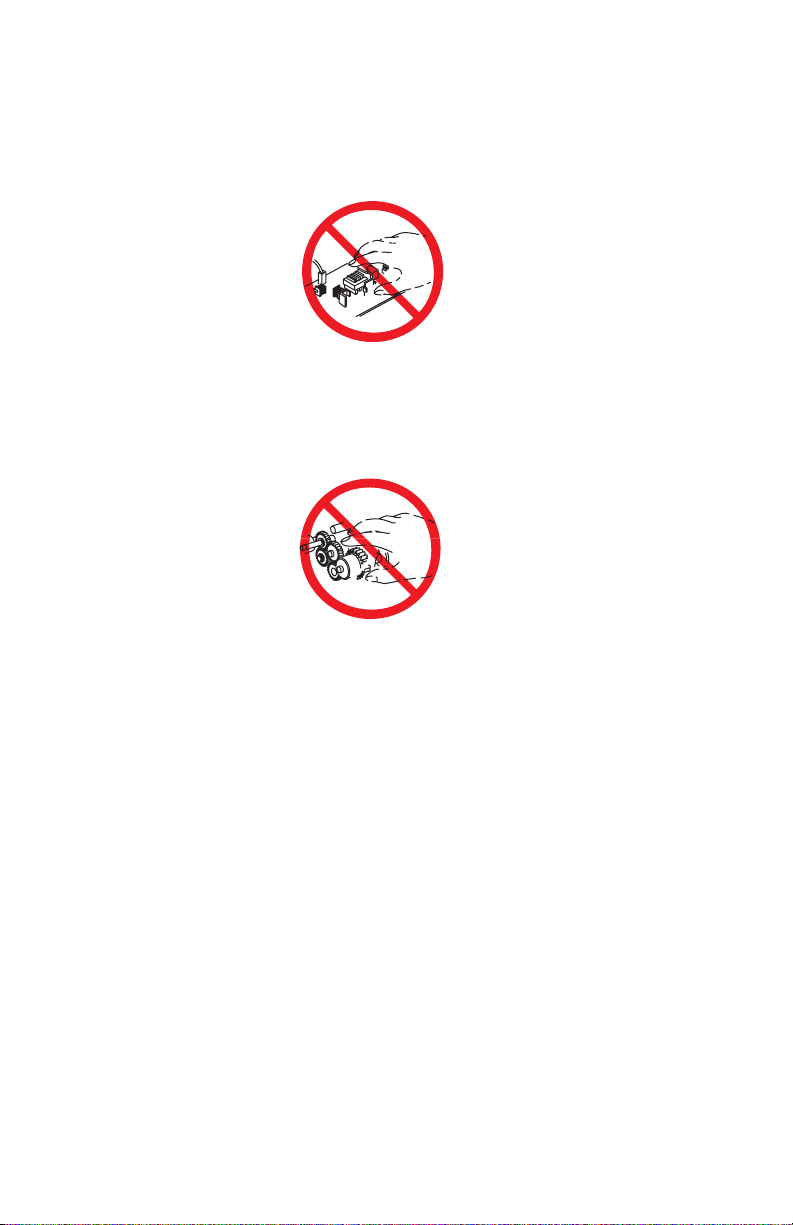
Power Supply and Electrical Components:
Before starting any service procedure,
switch off the printer power and unplug the power cord from the wall outlet. If you must
service the printer with power applied, be aware of the potential for electrical shock.
Do not touch any electrical component unless you are instructed to do so by a service
procedure.
S5400-01
Mechanical Components: Manually rotate drive assemblies to inspect sprockets and
gears.
Do not try to manually rotate or manually stop the drive assemblies while any printer motor
is running.
S5400-02
Laser Components
War nin g: This printer generates a laser beam as part of the printing
process. The laser beam is a concentrated narrow beam of
infrared light. The laser beam in this machine is invisible.
Although you cannot see the beam, it can still cause severe
eye damage. Direct eye exposure to the laser beam may
cause eye injury or blindness.
To avoid permanent eye damage, follow these directions:
■ Before starting any service procedure, switch off the printer power and unplug
the power cord from the AC wall outlet.
■ Do not disassemble the Raster Output Scanner Assembly (laser scanner) or any
laser component that displays a Laser Warning Sticker.
■ Use caution when you are working around the Raster Output Scanner Assembly
or when you are performing laser related troubleshooting or repair procedures.
■ Never place a mirror or a reflective tool or object in the laser beam path.
■ Do not disassemble the printer in such a way that the laser beam can exit the
print engine during a print cycle.
iv Phaser 5400 Laser Printer Service Guide
Page 6

Fuser Components
Warning: This printer uses heat and pressure to fuse the toner image
to a sheet of paper. The Fuser Assembly is very hot. Switch
off printer power and wait at least 30 minutes for the Fuser
to cool before you attempt to service the Fuser Assembly or
adjacent components.
Safety Components:
Make sure covers and panels are in place and that all interlock
switches are all functioning correctly after you have completed a printer service call. If
you bypass, or cheat, an interlock switch during a service call, use extreme caution when
working on or around the printer.
Warning Labels: Throughout the printer, warning labels are displayed on potentially
dangerous components. When you service the printer, check to make certain that all
warning labels are in place.
Most importantly, read and obey all posted warning labels.
Warning: Turning the power off using the On/Off switch does not
de-energize the printer. You must remove the power cord to
disconnect the printer from the main power source. Keep the
power cord accessible for removal in case of an emergency.
Safety Instructions:
Read all installation instructions carefully before you plug the
product into a power source.
Care of Product: Disconnect the power plug by pulling the plug, not the cord.
Disconnect the power plug:
■ If the power cord or plug is frayed or otherwise damaged,
■ If any liquid or foreign material is spilled into the case,
■ If the printer is exposed to any excess moisture,
■ If the printer is dropped or damaged,
■ If you suspect that the product needs servicing or repair, or
■ Whenever you clean the product.
Ground the product: Plug the three-wire power cord (with grounding prong) into
grounded AC outlets only. If necessary, contact a licensed electrician to install a properly
grounded outlet.
Phaser 5400 Laser Printer Service Guide v
Page 7

Service Safety Summary
For qualified service personnel only: Refer also to the preceding Users Safety
Summary.
Do not service alone: Do not perform internal service or adjustment of this product
unless another person capable of rendering first aid or resuscitation is present.
Use care when servicing with power: Dangerous voltages may exist at several points in
this product. To avoid personal injury, do not touch exposed connections and components
while power is on.
Disconnect power before removing the power supply shield, soldering or replacing
components.
Do not wear jewelry: Remove jewelry prior to servicing. Rings, necklaces and other
metallic objects could come into contact with dangerous voltages and currents.
Power source: This product is intended to operate from a power source that will not apply
more then 250 VAC rms between the supply conductors or between either supply
conductor and ground. A protective ground connection by way of the grounding
conductor in the power cord is essential for safe operation.
This product is certified under IEC 825 as a Class 1 Laser Product.
CLASS 1 LASER PRODUCT
The Phaser 5400 Laser Printer is certified to comply with Laser Product Performance
Standards set by the U.S. Department of Health and Human Services as a Class 1 Laser
Product. This means that this is a class of laser product that does not emit hazardous laser
radiation; this is possible only because the laser beam is totally enclosed during all modes
of customer operation.
The laser and output of the laser scanner unit produces a beam that, if looked into, could
cause eye damage. Service procedures must be followed exactly as written without
change.
When servicing the machine or laser module, follow the procedures specified in the
manual and there will be no hazards from the laser.
Laser (FDA): Any laser label visible to service must be reproduced in the service manual
with location shown or indicated. Safe working procedures and clear warnings concerning
precautions to avoid possible exposure must also be included.
vi Phaser 5400 Laser Printer Service Guide
Page 8

The Laser contained in the Phaser 5400 Laser Printer meets the following standard: Laser
class 3B, maximum 5 mW, wavelength 780 nm.
The following LASER symbol will be displayed at the start of any procedure where
possible exposure to the laser beam exists.
LUOKAN 1 LASERLAITE
KLASS 1 LASER APPARAT
Phaser 5400 Laser Printer Service Guide vii
Page 9

Federal Communications Commission Compliance
This equipment has been tested and found to comply with the limits set for a Class A
digital device, as stated in Part 15 of the FCC rules. These limits are designed to provide
reasonable protection against harmful interference in a commercial installation. This
equipment generates, uses, and may radiate radio frequency energy. If not installed and
used in accordance with the instructions provided, this equipment may cause disruptive
interference to nearby radio and television communications. Even if the equipment is
installed according to the instructions, there is no guarantee that interference will not
occur in a particular installation. If this equipment does cause disruptive interference to
nearby radio and television reception, switch the equipment off to determine if it is the
true cause of the interference. If the equipment is the cause of the interference, the user
should try to minimize the interference by taking one or more of the following courses of
action:
■ Either re–orient or relocate the radio/television receiving antenna.
■ Increase the separation between the equipment and the radio/television receiver.
■ Connect the equipment to an AC outlet that is not on the same circuit as the
radio/television receiver.
■ If the previous solutions fail to bring results, you should consult either your equipment
dealer or an experienced radio/television technician.
For more information on interference, refer to the Federal Communications Commission’s
booklet “How to Identify and Resolve Radio-TV Interference Problems”. This booklet is
available from the U.S. Government Printing Office, Washington D.C. 20402, Stock No.
004-000-00345-4.
viii Phaser 5400 Laser Printer Service Guide
Page 10

Canadian Notice
This digital apparatus does not exceed the Class A limits for radio noise emissions from
digital apparatus as described in the radio interference regulations of the Canadian
Department of Communications.
Avis Canadien
Cet appareil numerique est conforme aux limites émission de bruits radioélectriques pour
les appareils de classe A stipulés das le réglement sur le brouillage radioéletrique du
Ministére des Communcations du Canada.
European Notice
This equipment was tested and is determined to be compliant with VDE requirements for a
Class A device.
Hinweis
Hiermit wird bescheinigt, dass der Babe Laserdrucker, in bereinstimmung mit den
Betimmunngen der Vfg 104ß 984 funkenstört ist. Der Deutschen Bundespost wurde das
Inverkehrbringen dieses Gertëes angqeigt und die Berechtigung zur berprufung der Serie
auf Einhaltung der Bestimmungen eingeräumt.
Phaser 5400 Laser Printer Service Guide ix
Page 11

Blank Page
x Phaser 5400 Laser Printer Service Guide
Page 12

Table of Contents
Copyright .................................................................................................. ii
Users Safety Summary ........................................................................... iii
Service Safety Summary ......................................................................... vi
List of Figures . . . . . . . . . . . . . . . . . . . . . . . . . . . . . . . . . . . . . . . . xix
List of Tables. . . . . . . . . . . . . . . . . . . . . . . . . . . . . . . . . . . . . . . . . xxv
General Information . . . . . . . . . . . . . . . . . . . . . . . . . . . . . . . . . . . . . 1
Parts of the Printer ...................................................................................4
Printer Components ...........................................................................4
Printer Options ...................................................................................5
Control Panel .....................................................................................6
Display Screen...................................................................................7
Rear Panel .........................................................................................8
Print Engine Assemblies ..........................................................................9
Paper Path Information ..........................................................................15
Printer Specifications..............................................................................17
RAM and Printer Capabilities...........................................................17
Basic Specifications .........................................................................18
Electrical Specifications ...................................................................18
Mechanical Specifications ...............................................................19
Environmental Specifications...........................................................20
Life Expectancies.............................................................................21
Conforming Regulations and Standards ..........................................21
Printing Speed .................................................................................22
Printing Media Feeding Means ........................................................23
Printing Media ..................................................................................24
Printing Accuracy .............................................................................25
Components to Be Replaced Periodically .......................................26
Options ............................................................................................26
Phaser 5400 Laser Printer Service Guide xi
Page 13

Error Codes and Messages . . . . . . . . . . . . . . . . . . . . . . . . . . . . . .27
Introduction ............................................................................................28
Error messages ...............................................................................28
Measurements .................................................................................29
Service Flowchart ............................................................................29
Repair Analysis Procedure Table...........................................................31
How to Use a Repair Analysis Procedure Table..............................31
How to Follow a Repair Analysis Procedure....................................32
General Notes on Using Repair Analysis Procedures .....................33
Error Codes with Repair Analysis Procedure .........................................35
Troubleshooting . . . . . . . . . . . . . . . . . . . . . . . . . . . . . . . . . . . . . . 107
Printer Performance Problems Repair Analysis Procedure
(RAP) Table.............................................................................107
Image-Quality Problems Repair Analysis Procedure (RAP) Table ......109
Electrical Interference Repair Analysis Procedure (RAP) Table ..........109
Printer Performance Problems .............................................................110
Image-Quality Troubleshooting ............................................................176
Introduction ....................................................................................176
Image-Quality Defect Definitions ...................................................177
Diagnostics, Test Prints, Service Tests and
NVRAM Adjustments . . . . . . . . . . . . . . . . . . . . . . . . . . . . . . . 219
Entering Diagnostics Mode ..................................................................221
System Controller Board Error (Blink) Codes.......................................222
Recommended Corrective Action ..................................................223
Power On LED Sequence..............................................................223
Diagnostics Menu Map ..................................................................224
System Controller Board Test Prints ....................................................226
Main Menu Test Prints .........................................................................226
Configuration Sheet .......................................................................226
System Controller Board Test Print ...............................................227
Fault History...................................................................................227
Display Faults ................................................................................227
Menu Map......................................................................................227
PS Font List ...................................................................................228
PCL Font List: ................................................................................228
PCL Demo: ....................................................................................228
Print Engine Controller Board Test Print ..............................................229
Analyzing Test Prints ...........................................................................230
Registration ..........................................................................................231
NVRAM Configuration (NVM Config) ...................................................233
xii Phaser 5400 Laser Printer Service Guide
Page 14

Component Tests .................................................................................235
Reset Menu ..........................................................................................239
Maintenance Kit Counter Reset Procedure..........................................240
Maintenance and Cleaning. . . . . . . . . . . . . . . . . . . . . . . . . . . . . . 241
Scheduled Maintenance.......................................................................241
Recommended Tools ...........................................................................241
Inspect While Servicing ........................................................................241
General Cleaning (if needed) ...............................................................242
FRU Removal / Replacement Procedures (RRPs) . . . . . . . . . . . 245
Contents - Removal and Replacement Procedures .............................245
Introduction...........................................................................................248
Work Notes...........................................................................................248
Preparation...........................................................................................249
Notations in the RRP text .....................................................................249
Adjustment ...........................................................................................249
Repair Procedures ...............................................................................250
RRP 1.1 Left Side Cover ...............................................................250
RRP 1.2 Right Side Cover .............................................................251
RRP 1.3 Top Cover Assembly .......................................................252
RRP 1.4 Front Cover .....................................................................253
RRP 1.5 Lower Left Cover .............................................................254
RRP 1.6 HVPS Cover ....................................................................255
RRP 1.7 Lower Rear Cover ...........................................................256
RRP 1.8 MBF Gear Cover .............................................................257
RRP 1.9 Rear Cover ......................................................................258
RRP 2.1 Multi-sheet Bypass Feeder (MBF) Assembly ..................259
RRP 2.2 MBF Feed Rollers ...........................................................261
RRP 2.3 MBF Tray 1 Turn Roller Clutch Assembly .......................262
RRP 2.4 Tray 1 Turn Roller Assembly...........................................263
RRP 2.5 MBF Retard Holder Assembly.........................................264
RRP 2.6 Tray 1 No Paper Sensor Assembly .................................266
RRP 2.7 MBF No Paper Sensor Assembly ...................................267
RRP 2.8 MBF Feed Solenoid ........................................................269
RRP 2.9 Tray 1 Feed Solenoid ......................................................270
RRP 2.10 Tray 1 Feed Roller ........................................................271
RRP 2.11 Tray 1 Retard Holder Assembly ....................................272
RRP 3.1 Retard Chute Assembly ..................................................273
RRP 3.2 Rear Chute Assembly .....................................................274
RRP 3.3 Lower Turn Roller Assembly ...........................................275
RRP 3.4 Tray 1 Low Paper Sensor ...............................................276
Phaser 5400 Laser Printer Service Guide xiii
Page 15

RRP 3.5 Tray 1 Right Guide Assembly .........................................277
RRP 3.6 Tray 1 Left Guide Assembly............................................279
RRP 3.7 CRUM Board ...................................................................281
RRP 3.8 MBF Assembly Position Sensor ......................................282
RRP 4.1 Paper Transport Assembly..............................................283
RRP 4.2 Registration Actuator.......................................................285
RRP 4.3 Registration Clutch ..........................................................286
RRP 4.4 Registration Sensor.........................................................287
RRP 5.1 Fuser Assembly ..............................................................288
RRP 5.2 Stack Full Sensor ............................................................289
RRP 5.3 Exit Roller Assembly .......................................................291
RRP 5.4 Stack Full Sensor Actuator..............................................294
RRP 6.1 Main Drive Gear Assembly .............................................295
RRP 7.1 Laser Assembly...............................................................297
RRP 7.2 Right Print Cartridge Guide Assembly ............................299
RRP 7.3 Toner Sensor Assembly..................................................301
RRP 7.4 Top Cover Interlock Switch .............................................302
RRP 7.5 Left Print Cartridge Guide Assembly ...............................303
RRP 7.6 Bias Transfer Roller [BTR] Assembly..............................304
RRP 8.1 System Controller PWB ..................................................305
RRP 8.2 High-Voltage Power Supply [HVPS] Board.....................307
RRP 8.3 Duplex Interface Board ...................................................308
RRP 8.4 Main Fan .........................................................................309
RRP 8.5 Print Engine Controller Board .........................................310
RRP 8.6 Low-Voltage Power Supply [LVPS] Assembly ................312
RRP 8.7 LVPS FAN .......................................................................313
RRP 8.8 AC Input Assembly..........................................................314
RRP 8.9 Control Panel +5 VDC Power Supply..............................315
RRP 9.1 Duplex Assembly ............................................................317
RRP 10.1 1000-Sheet High Capacity Stacker [HCS] ....................318
RRP 10.2 HCS Top Cover .............................................................319
RRP 10.3 HCS Rear Cover Assembly...........................................320
RRP 10.4 HCS Front Cover...........................................................321
RRP 10.5 HCS Exit Gate Solenoid................................................322
RRP 10.6 HCS Stack Full Sensor .................................................323
RRP 10.7 HCS Stack Full Sensor Actuator ...................................324
RRP 10.8 HCS Drive Motor Assembly ..........................................325
RRP 10.9 HCS Rear Cover Interlock Switch .................................326
RRP 10.10 HCS Paper Sensor......................................................327
RRP 11.1 500-Sheet Feeder Removal ..........................................328
RRP 11.2 Front Cover ...................................................................329
RRP 11.3 Left Cover......................................................................330
RRP 11.4 Right Cover ...................................................................331
xiv Phaser 5400 Laser Printer Service Guide
Page 16

RRP 11.5 Rear Cover ....................................................................332
RRP 11.6 Drive Assembly .............................................................333
RRP 11.7 Feeder Board ................................................................334
RRP 11.8 Feed Head Assembly....................................................335
RRP 11.9 Feed Rollers ..................................................................336
RRP 11.10 Feed Solenoid .............................................................337
RRP 11.11 Turn Roller Assembly..................................................338
RRP 11.12 Retard Chute Assembly ..............................................339
RRP 11.13 Left Tray Guide ...........................................................340
RRP 11.14 Right Tray Guide .........................................................342
RRP 11.15 Retard Holder Assembly .............................................344
RRP 11.16 Retard Turn Roller Assembly ......................................345
RRP 11.17 Paper Size Sensor ......................................................346
RRP 11.18 Paper Tray Sensor ......................................................347
RRP 11.19 No Paper Sensor.........................................................348
RRP 11.20 No Paper Sensor Actuator ..........................................350
RRP 11.21 Preregistration Sensor ................................................351
RRP 12.1 Removing the 2000-Sheet Feeder ................................352
RRP 12.2 Left Side Cover .............................................................354
RRP 12.3 Upper Rear Cover .........................................................355
RRP 12.4 Lower Rear Cover .........................................................356
RRP 12.5 Right Side Cover ...........................................................357
RRP 12.6 Front Cover ...................................................................358
RRP 12.7 Tray Assembly ..............................................................359
RRP 12.8 2000-Sheet Feeder PWB ..............................................360
RRP 12.9 Tray Lift Motor Assembly ..............................................361
RRP 12.10 A4 Paper Size Sensor.................................................362
RRP 12.11 Casters ........................................................................363
RRP 12.12 Harness Assembly ......................................................364
RRP 12.13 Drive Assembly ...........................................................365
RRP 12.14 Feed, Nudger, and Retard Roller ................................366
RRP 12.15 Paper Height Sensor...................................................367
RRP 12.16 Paper Feed Motor Assembly.......................................368
RRP 12.17 Link Stopper ................................................................369
RRP 12.18 No Paper Sensor.........................................................370
RRP 12.19 No Paper Sensor Actuator ..........................................371
RRP 12.20 Left and Right Wire Cover...........................................372
RRP 12.21 Shaft Cover Assembly.................................................373
RRP 12.22 Drive Shaft Assembly ..................................................374
RRP 12.23 Brake Assembly ..........................................................375
RRP 12.24 Left Tray Wires ............................................................376
RRP 12.25 Right Tray Wires .........................................................377
RRP 12.26 Retard Assembly.........................................................378
Phaser 5400 Laser Printer Service Guide xv
Page 17

FRU Parts List . . . . . . . . . . . . . . . . . . . . . . . . . . . . . . . . . . . . . . . . 381
Introduction ..........................................................................................381
Organization of this Section...........................................................381
Using the Parts List........................................................................382
Parts Lists ............................................................................................384
PL 1.1 Covers ................................................................................384
PL 2.1 Paper Tray [A3/Ledger] ......................................................386
PL 2.2 Paper Tray [A4/Letter] ........................................................388
PL 3.1 Paper Feeder .....................................................................390
PL 4.1 Multi-sheet Bypass Feeder (MBF) Assembly .....................392
PL 4.2 Paper Handler ....................................................................394
PL 5.1 Paper Transport .................................................................396
PL 6.1 Rear Cover Assembly With Fuser ......................................398
PL 7.1 Frame & Drives ..................................................................400
PL 8.1 Xerographics ......................................................................402
PL 9.1 Electrical (1 of 2) ................................................................404
PL 9.2 Electrical (2 of 2) ................................................................406
PL 10.1 High Capacity Stacker [HCS] (1 of 2) ...............................408
PL 10.2 High Capacity Stacker [HCS] (2 of 2) ...............................410
PL 11.1 500-Sheet Feeder (1 of 3) ................................................412
PL 11.2 500-Sheet Feeder (2 of 3) ................................................414
PL 11.3 500-Sheet Feeder (3 of 3) ................................................416
PL 12.1 2000-Sheet Feeder (1 of 4) ..............................................418
PL 12.2 2000-Sheet Feeder (2 of 4) ..............................................420
PL 12.3 2000-Sheet Feeder (3 of 4) ..............................................422
PL 12.4 2000-Sheet Feeder (4 of 4) ..............................................424
PL 13.1 Duplex Assembly..............................................................426
Xerox Supplies and Accessories..........................................................428
Plug/Jack Connector Locations. . . . . . . . . . . . . . . . . . . . . . . . . .433
Contents ...............................................................................................433
Plug/Jack (P/J) Locations for the Engine .............................................434
Plug/Jack Location Map 1 - Engine......................................................437
Plug/Jack Location Map 2 - Engine......................................................438
Plug/Jack Location Map 3 - Engine......................................................439
Plug/Jack Location Map 4 - 500-Sheet Feeder ....................................440
Plug/Jack Location Map 5 - Duplex Assembly .....................................442
Plug/Jack Location - 1000-Sheet (High Capacity) Stacker ..................444
Plug/Jack Location - 2000-Sheet Feeder .............................................446
Plug/Jack Location Map 7 - 2000-Sheet Feeder ..................................447
xvi Phaser 5400 Laser Printer Service Guide
Page 18

Wiring Diagrams . . . . . . . . . . . . . . . . . . . . . . . . . . . . . . . . . . . . . . 449
Wiring Diagram Notations ....................................................................449
Organization .........................................................................................450
Master Connection and Wiring Diagram ........................................451
Base Engine Wiring Diagrams.......................................................454
500-Sheet Feeder ..........................................................................465
Duplex Assembly ...........................................................................467
1000-Sheet (High Capacity Stacker) .............................................468
2000-Sheet Feeder ........................................................................469
Phaser 5400 Laser Printer Service Guide xvii
Page 19

Blank Page
xviii Phaser 5400 Laser Printer Service Guide
Page 20

List of Figures
Figure 1 Machine Orientation . . . . . . . . . . . . . . . . . . . . . . . . . . . . . . . . . . . . . . . . . . . . 1
Figure 2 Front View . . . . . . . . . . . . . . . . . . . . . . . . . . . . . . . . . . . . . . . . . . . . . . . . . . . 4
Figure 3 Rear View. . . . . . . . . . . . . . . . . . . . . . . . . . . . . . . . . . . . . . . . . . . . . . . . . . . . 4
Figure 4 View from Right Front. . . . . . . . . . . . . . . . . . . . . . . . . . . . . . . . . . . . . . . . . . . 5
Figure 5 View from Left Rear . . . . . . . . . . . . . . . . . . . . . . . . . . . . . . . . . . . . . . . . . . . . 5
Figure 6 Control Panel . . . . . . . . . . . . . . . . . . . . . . . . . . . . . . . . . . . . . . . . . . . . . . . . . 6
Figure 7 Rear Panel . . . . . . . . . . . . . . . . . . . . . . . . . . . . . . . . . . . . . . . . . . . . . . . . . . . 8
Figure 8 Print Engine Assemblies, Sensors and Interlock Locations 1 -
Tray 1 and MBF Paper Path Components 1 . . . . . . . . . . . . . . . . . . . . . . . 9
Figure 9 FRU Assemblies, Sensors and Interlock Locations 2 . . . . . . . . . . . . . . . . . 10
Figure 10 FRU Assemblies, Sensors and Interlock Locations 3 - Detack Saw,
Registration & Bias Transfer Rollers and Paper Transport Assembly . . . 11
Figure 11 FRU Assemblies, Sensors and Interlock Locations 4 - Fuser Area . . . . . . 12
Figure 12 FRU Assemblies, Sensors and Interlock Locations 5 - Main Drive . . . . . . 13
Figure 13 FRU Assemblies, Sensors and Interlock Locations 6 -
FRU Circuit Assemblies . . . . . . . . . . . . . . . . . . . . . . . . . . . . . . . . . . . . . . 14
Figure 14 Paper Path Flow. . . . . . . . . . . . . . . . . . . . . . . . . . . . . . . . . . . . . . . . . . . . . 15
Figure 15 Paper Path Components . . . . . . . . . . . . . . . . . . . . . . . . . . . . . . . . . . . . . . 16
Figure 16 Service Flowchart. . . . . . . . . . . . . . . . . . . . . . . . . . . . . . . . . . . . . . . . . . . . 30
Figure 17 Fuser Connector P174 . . . . . . . . . . . . . . . . . . . . . . . . . . . . . . . . . . . . . . . 134
Figure 18 Light Prints . . . . . . . . . . . . . . . . . . . . . . . . . . . . . . . . . . . . . . . . . . . . . . . . 178
Figure 19 Blank Prints . . . . . . . . . . . . . . . . . . . . . . . . . . . . . . . . . . . . . . . . . . . . . . . 181
Figure 20 Spots . . . . . . . . . . . . . . . . . . . . . . . . . . . . . . . . . . . . . . . . . . . . . . . . . . . . 183
Figure 21 Horizontal (Scan) Deletions . . . . . . . . . . . . . . . . . . . . . . . . . . . . . . . . . . . 185
Figure 22 Vertical (Process) Deletions. . . . . . . . . . . . . . . . . . . . . . . . . . . . . . . . . . . 188
Figure 23 Spot Deletions . . . . . . . . . . . . . . . . . . . . . . . . . . . . . . . . . . . . . . . . . . . . . 190
Figure 24 Vertical (Process) Streaks . . . . . . . . . . . . . . . . . . . . . . . . . . . . . . . . . . . . 192
Figure 25 Horizontal (Scan) Streaks . . . . . . . . . . . . . . . . . . . . . . . . . . . . . . . . . . . . 194
Figure 26 Residual Image . . . . . . . . . . . . . . . . . . . . . . . . . . . . . . . . . . . . . . . . . . . . 197
Figure 27 Black Prints . . . . . . . . . . . . . . . . . . . . . . . . . . . . . . . . . . . . . . . . . . . . . . . 199
Figure 28 Background . . . . . . . . . . . . . . . . . . . . . . . . . . . . . . . . . . . . . . . . . . . . . . . 200
Figure 29 Uneven Density . . . . . . . . . . . . . . . . . . . . . . . . . . . . . . . . . . . . . . . . . . . . 202
Figure 30 Skewed Image . . . . . . . . . . . . . . . . . . . . . . . . . . . . . . . . . . . . . . . . . . . . . 204
Figure 31 Damaged Print . . . . . . . . . . . . . . . . . . . . . . . . . . . . . . . . . . . . . . . . . . . . . 210
Figure 32 Registration . . . . . . . . . . . . . . . . . . . . . . . . . . . . . . . . . . . . . . . . . . . . . . . 212
Figure 33 Skips / Smears . . . . . . . . . . . . . . . . . . . . . . . . . . . . . . . . . . . . . . . . . . . . . 214
Figure 34 Unfused Image . . . . . . . . . . . . . . . . . . . . . . . . . . . . . . . . . . . . . . . . . . . . . 215
Figure 35 Registration Test Pattern . . . . . . . . . . . . . . . . . . . . . . . . . . . . . . . . . . . . . 232
Phaser 5400 Laser Printer Service Guide xix
Page 21

Figure 36 Removing the Left Side Cover. . . . . . . . . . . . . . . . . . . . . . . . . . . . . . . . . 250
Figure 37 Right Side Cover . . . . . . . . . . . . . . . . . . . . . . . . . . . . . . . . . . . . . . . . . . . 251
Figure 38 Top Cover Assembly . . . . . . . . . . . . . . . . . . . . . . . . . . . . . . . . . . . . . . . . 252
Figure 39 Front Cover . . . . . . . . . . . . . . . . . . . . . . . . . . . . . . . . . . . . . . . . . . . . . . . 253
Figure 40 Lower Left Cover . . . . . . . . . . . . . . . . . . . . . . . . . . . . . . . . . . . . . . . . . . . 254
Figure 41 HVPS Cover . . . . . . . . . . . . . . . . . . . . . . . . . . . . . . . . . . . . . . . . . . . . . . 255
Figure 42 Lower Rear Cover . . . . . . . . . . . . . . . . . . . . . . . . . . . . . . . . . . . . . . . . . . 256
Figure 43 MBF Gear Cover . . . . . . . . . . . . . . . . . . . . . . . . . . . . . . . . . . . . . . . . . . . 257
Figure 44 Rear Cover . . . . . . . . . . . . . . . . . . . . . . . . . . . . . . . . . . . . . . . . . . . . . . . 258
Figure 45 MBF Paper Handler Assembly . . . . . . . . . . . . . . . . . . . . . . . . . . . . . . . . 259
Figure 46 MBF Left Tray Stop . . . . . . . . . . . . . . . . . . . . . . . . . . . . . . . . . . . . . . . . . 260
Figure 47 MBF Right Tray Stop . . . . . . . . . . . . . . . . . . . . . . . . . . . . . . . . . . . . . . . . 260
Figure 48 MBF Feed Roller Assembly . . . . . . . . . . . . . . . . . . . . . . . . . . . . . . . . . . . 261
Figure 49 MBF Tray 1 Turn Roller Clutch Assembly . . . . . . . . . . . . . . . . . . . . . . . . 262
Figure 50 Tray 1 Turn Roller Assembly . . . . . . . . . . . . . . . . . . . . . . . . . . . . . . . . . . 263
Figure 51 MBF Pick Up Shaft . . . . . . . . . . . . . . . . . . . . . . . . . . . . . . . . . . . . . . . . . 264
Figure 52 MBF Tray Assembly . . . . . . . . . . . . . . . . . . . . . . . . . . . . . . . . . . . . . . . . 265
Figure 53 MBF Retard Holder Assembly . . . . . . . . . . . . . . . . . . . . . . . . . . . . . . . . . 265
Figure 54 Tray 1 No Paper Sensor Assembly . . . . . . . . . . . . . . . . . . . . . . . . . . . . . 266
Figure 55 MBF No Paper Sensor Assembly . . . . . . . . . . . . . . . . . . . . . . . . . . . . . . 267
Figure 56 MBF Tray Assembly . . . . . . . . . . . . . . . . . . . . . . . . . . . . . . . . . . . . . . . . 268
Figure 57 MBF No Paper Sensor Assembly . . . . . . . . . . . . . . . . . . . . . . . . . . . . . . 268
Figure 58 MBF Feed Solenoid . . . . . . . . . . . . . . . . . . . . . . . . . . . . . . . . . . . . . . . . . 269
Figure 59 Tray 1 Feed Solenoid . . . . . . . . . . . . . . . . . . . . . . . . . . . . . . . . . . . . . . . 270
Figure 60 Tray 1 Feed Roller . . . . . . . . . . . . . . . . . . . . . . . . . . . . . . . . . . . . . . . . . . 271
Figure 61 Tray 1 Retard Holder Assembly. . . . . . . . . . . . . . . . . . . . . . . . . . . . . . . . 272
Figure 62 Rear Chute Assembly . . . . . . . . . . . . . . . . . . . . . . . . . . . . . . . . . . . . . . . 273
Figure 63 Rear Chute Assembly . . . . . . . . . . . . . . . . . . . . . . . . . . . . . . . . . . . . . . . 274
Figure 64 Lower Turn Roller Assembly . . . . . . . . . . . . . . . . . . . . . . . . . . . . . . . . . . 275
Figure 65 Tray 1 Low Paper Sensor . . . . . . . . . . . . . . . . . . . . . . . . . . . . . . . . . . . . 276
Figure 66 Paper Level Indicator Arm . . . . . . . . . . . . . . . . . . . . . . . . . . . . . . . . . . . . 277
Figure 67 Tray 1 Right Guide Assembly . . . . . . . . . . . . . . . . . . . . . . . . . . . . . . . . . 278
Figure 68 Tray Left Guide Assembly . . . . . . . . . . . . . . . . . . . . . . . . . . . . . . . . . . . . 279
Figure 69 Removing the CRUM Board . . . . . . . . . . . . . . . . . . . . . . . . . . . . . . . . . . 281
Figure 70 MBF Assembly Position Sensor . . . . . . . . . . . . . . . . . . . . . . . . . . . . . . . 282
Figure 71 Paper Transport Assembly . . . . . . . . . . . . . . . . . . . . . . . . . . . . . . . . . . . 283
Figure 72 Registration Actuator . . . . . . . . . . . . . . . . . . . . . . . . . . . . . . . . . . . . . . . . 285
Figure 73 Registration Clutch . . . . . . . . . . . . . . . . . . . . . . . . . . . . . . . . . . . . . . . . . 286
Figure 74 Registration Sensor . . . . . . . . . . . . . . . . . . . . . . . . . . . . . . . . . . . . . . . . . 287
Figure 75 Fuser Assembly. . . . . . . . . . . . . . . . . . . . . . . . . . . . . . . . . . . . . . . . . . . . 288
Figure 76 Lower Exit Chute . . . . . . . . . . . . . . . . . . . . . . . . . . . . . . . . . . . . . . . . . . . 289
Figure 77 Upper Exit Chute . . . . . . . . . . . . . . . . . . . . . . . . . . . . . . . . . . . . . . . . . . . 290
Figure 78 Stack Full Sensor. . . . . . . . . . . . . . . . . . . . . . . . . . . . . . . . . . . . . . . . . . . 290
xx Phaser 5400 Laser Printer Service Guide
Page 22

Figure 79 Lower Exit Chute . . . . . . . . . . . . . . . . . . . . . . . . . . . . . . . . . . . . . . . . . . . 291
Figure 80 Upper Exit Chute . . . . . . . . . . . . . . . . . . . . . . . . . . . . . . . . . . . . . . . . . . . 292
Figure 81 Upper Exit Roller Assembly . . . . . . . . . . . . . . . . . . . . . . . . . . . . . . . . . . . 292
Figure 82 Lower Exit Roller Assembly . . . . . . . . . . . . . . . . . . . . . . . . . . . . . . . . . . . 293
Figure 83 Stack Full Sensor Actuator. . . . . . . . . . . . . . . . . . . . . . . . . . . . . . . . . . . . 294
Figure 84 Shield Cover. . . . . . . . . . . . . . . . . . . . . . . . . . . . . . . . . . . . . . . . . . . . . . . 295
Figure 85 Gear Drive Assembly . . . . . . . . . . . . . . . . . . . . . . . . . . . . . . . . . . . . . . . . 296
Figure 86 Laser Cover . . . . . . . . . . . . . . . . . . . . . . . . . . . . . . . . . . . . . . . . . . . . . . . 297
Figure 87 Laser Assembly . . . . . . . . . . . . . . . . . . . . . . . . . . . . . . . . . . . . . . . . . . . . 298
Figure 88 Right Print Cartridge Guide . . . . . . . . . . . . . . . . . . . . . . . . . . . . . . . . . . . 299
Figure 89 Toner Sensor Assembly . . . . . . . . . . . . . . . . . . . . . . . . . . . . . . . . . . . . . . 301
Figure 90 Top Cover Interlock Switch . . . . . . . . . . . . . . . . . . . . . . . . . . . . . . . . . . . 302
Figure 91 Left Print Cartridge Guide Assembly . . . . . . . . . . . . . . . . . . . . . . . . . . . . 303
Figure 92 Bias Transfer Roller [BTR] Assembly. . . . . . . . . . . . . . . . . . . . . . . . . . . . 304
Figure 93 Shield Cover. . . . . . . . . . . . . . . . . . . . . . . . . . . . . . . . . . . . . . . . . . . . . . . 305
Figure 94 System Controller Board Assembly . . . . . . . . . . . . . . . . . . . . . . . . . . . . . 306
Figure 95 System Controller Board . . . . . . . . . . . . . . . . . . . . . . . . . . . . . . . . . . . . . 306
Figure 96 High-Voltage Power Supply [HVPS] Board . . . . . . . . . . . . . . . . . . . . . . . 307
Figure 97 Duplex Interface Board. . . . . . . . . . . . . . . . . . . . . . . . . . . . . . . . . . . . . . . 308
Figure 98 Main Fan . . . . . . . . . . . . . . . . . . . . . . . . . . . . . . . . . . . . . . . . . . . . . . . . . 309
Figure 99 Shield Cover. . . . . . . . . . . . . . . . . . . . . . . . . . . . . . . . . . . . . . . . . . . . . . . 310
Figure 100 Print Engine Controller Board Cover . . . . . . . . . . . . . . . . . . . . . . . . . . . 311
Figure 101 Print Engine Controller Board. . . . . . . . . . . . . . . . . . . . . . . . . . . . . . . . . 311
Figure 102 Low-Voltage Power Supply [LVPS] . . . . . . . . . . . . . . . . . . . . . . . . . . . . 312
Figure 103 LVPS Fan. . . . . . . . . . . . . . . . . . . . . . . . . . . . . . . . . . . . . . . . . . . . . . . . 313
Figure 104 AC Input Assembly. . . . . . . . . . . . . . . . . . . . . . . . . . . . . . . . . . . . . . . . . 314
Figure 105 Print Engine Controller Board Cover . . . . . . . . . . . . . . . . . . . . . . . . . . . 315
Figure 106 +5 VDC Power Supply . . . . . . . . . . . . . . . . . . . . . . . . . . . . . . . . . . . . . . 316
Figure 107 Duplex Assembly . . . . . . . . . . . . . . . . . . . . . . . . . . . . . . . . . . . . . . . . . . 317
Figure 108 High Capacity Stacker [HCS] Assembly. . . . . . . . . . . . . . . . . . . . . . . . . 318
Figure 109 HCS Top Cover . . . . . . . . . . . . . . . . . . . . . . . . . . . . . . . . . . . . . . . . . . . 319
Figure 110 HCS Rear Cover . . . . . . . . . . . . . . . . . . . . . . . . . . . . . . . . . . . . . . . . . . 320
Figure 111 HCS Front Cover . . . . . . . . . . . . . . . . . . . . . . . . . . . . . . . . . . . . . . . . . . 321
Figure 112 Exit Gate Solenoid . . . . . . . . . . . . . . . . . . . . . . . . . . . . . . . . . . . . . . . . . 322
Figure 113 HCS Stack Full Sensor. . . . . . . . . . . . . . . . . . . . . . . . . . . . . . . . . . . . . . 323
Figure 114 HCS Stack Full Sensor Actuator . . . . . . . . . . . . . . . . . . . . . . . . . . . . . . 324
Figure 115 HCS Drive Motor Assembly . . . . . . . . . . . . . . . . . . . . . . . . . . . . . . . . . . 325
Figure 116 HCS Rear Cover Interlock Switch . . . . . . . . . . . . . . . . . . . . . . . . . . . . . 326
Figure 117 HCS Paper Sensor. . . . . . . . . . . . . . . . . . . . . . . . . . . . . . . . . . . . . . . . . 327
Figure 118 Feeder Removal. . . . . . . . . . . . . . . . . . . . . . . . . . . . . . . . . . . . . . . . . . . 328
Figure 119 Front Cover . . . . . . . . . . . . . . . . . . . . . . . . . . . . . . . . . . . . . . . . . . . . . . 329
Figure 120 Left Cover. . . . . . . . . . . . . . . . . . . . . . . . . . . . . . . . . . . . . . . . . . . . . . . . 330
Figure 121 Right Cover . . . . . . . . . . . . . . . . . . . . . . . . . . . . . . . . . . . . . . . . . . . . . . 331
Phaser 5400 Laser Printer Service Guide xxi
Page 23

Figure 122 Rear Cover . . . . . . . . . . . . . . . . . . . . . . . . . . . . . . . . . . . . . . . . . . . . . . 332
Figure 123 Feeder Drive Assembly . . . . . . . . . . . . . . . . . . . . . . . . . . . . . . . . . . . . . 333
Figure 124 Feeder Board. . . . . . . . . . . . . . . . . . . . . . . . . . . . . . . . . . . . . . . . . . . . . 334
Figure 125 Feed Head Assembly . . . . . . . . . . . . . . . . . . . . . . . . . . . . . . . . . . . . . . 335
Figure 126 Feed Rollers . . . . . . . . . . . . . . . . . . . . . . . . . . . . . . . . . . . . . . . . . . . . . 336
Figure 127 Feed Solenoid . . . . . . . . . . . . . . . . . . . . . . . . . . . . . . . . . . . . . . . . . . . . 337
Figure 128 Turn Roller Assembly . . . . . . . . . . . . . . . . . . . . . . . . . . . . . . . . . . . . . . 338
Figure 129 Retard Chute Assembly. . . . . . . . . . . . . . . . . . . . . . . . . . . . . . . . . . . . . 339
Figure 130 Left Tray Guide . . . . . . . . . . . . . . . . . . . . . . . . . . . . . . . . . . . . . . . . . . . 340
Figure 131 Paper Level Indicator Actuator . . . . . . . . . . . . . . . . . . . . . . . . . . . . . . . 342
Figure 132 Right Tray Guide . . . . . . . . . . . . . . . . . . . . . . . . . . . . . . . . . . . . . . . . . . 343
Figure 133 Retard Holder Assembly . . . . . . . . . . . . . . . . . . . . . . . . . . . . . . . . . . . . 344
Figure 134 Turn Roller Assembly . . . . . . . . . . . . . . . . . . . . . . . . . . . . . . . . . . . . . . 345
Figure 135 Paper Size Sensor. . . . . . . . . . . . . . . . . . . . . . . . . . . . . . . . . . . . . . . . . 346
Figure 136 Paper Tray Sensor. . . . . . . . . . . . . . . . . . . . . . . . . . . . . . . . . . . . . . . . . 347
Figure 137 No Paper Sensor Cover. . . . . . . . . . . . . . . . . . . . . . . . . . . . . . . . . . . . . 348
Figure 138 Feed Solenoid . . . . . . . . . . . . . . . . . . . . . . . . . . . . . . . . . . . . . . . . . . . . 349
Figure 139 No Paper Sensor . . . . . . . . . . . . . . . . . . . . . . . . . . . . . . . . . . . . . . . . . . 349
Figure 140 No Paper Sensor Actuator. . . . . . . . . . . . . . . . . . . . . . . . . . . . . . . . . . . 350
Figure 141 Sensor Cover. . . . . . . . . . . . . . . . . . . . . . . . . . . . . . . . . . . . . . . . . . . . . 351
Figure 142 Preregistration Sensor . . . . . . . . . . . . . . . . . . . . . . . . . . . . . . . . . . . . . . 351
Figure 143 Removing the Printer . . . . . . . . . . . . . . . . . . . . . . . . . . . . . . . . . . . . . . . 352
Figure 144 Left Side Cover . . . . . . . . . . . . . . . . . . . . . . . . . . . . . . . . . . . . . . . . . . . 354
Figure 145 Upper Rear Cover . . . . . . . . . . . . . . . . . . . . . . . . . . . . . . . . . . . . . . . . . 355
Figure 146 Lower Rear Cover . . . . . . . . . . . . . . . . . . . . . . . . . . . . . . . . . . . . . . . . . 356
Figure 147 Right Side Cover . . . . . . . . . . . . . . . . . . . . . . . . . . . . . . . . . . . . . . . . . . 357
Figure 148 Front Cover . . . . . . . . . . . . . . . . . . . . . . . . . . . . . . . . . . . . . . . . . . . . . . 358
Figure 149 Tray Assembly. . . . . . . . . . . . . . . . . . . . . . . . . . . . . . . . . . . . . . . . . . . . 359
Figure 150 2000-Sheet Feeder Board . . . . . . . . . . . . . . . . . . . . . . . . . . . . . . . . . . . 360
Figure 151 Tray Lift Motor Assembly. . . . . . . . . . . . . . . . . . . . . . . . . . . . . . . . . . . . 361
Figure 152 Paper Size Sensor. . . . . . . . . . . . . . . . . . . . . . . . . . . . . . . . . . . . . . . . . 362
Figure 153 Casters . . . . . . . . . . . . . . . . . . . . . . . . . . . . . . . . . . . . . . . . . . . . . . . . . 363
Figure 154 Harness Assembly. . . . . . . . . . . . . . . . . . . . . . . . . . . . . . . . . . . . . . . . . 364
Figure 155 Drive Assembly . . . . . . . . . . . . . . . . . . . . . . . . . . . . . . . . . . . . . . . . . . . 365
Figure 156 Pick, Feed and Retard Rollers. . . . . . . . . . . . . . . . . . . . . . . . . . . . . . . . 366
Figure 157 Paper Height Sensor . . . . . . . . . . . . . . . . . . . . . . . . . . . . . . . . . . . . . . . 367
Figure 158 Paper Feed Motor Assembly . . . . . . . . . . . . . . . . . . . . . . . . . . . . . . . . . 368
Figure 159 Link Stopper. . . . . . . . . . . . . . . . . . . . . . . . . . . . . . . . . . . . . . . . . . . . . . 369
Figure 160 No Paper Sensor . . . . . . . . . . . . . . . . . . . . . . . . . . . . . . . . . . . . . . . . . . 370
Figure 161 No Paper Sensor Actuator. . . . . . . . . . . . . . . . . . . . . . . . . . . . . . . . . . . 371
Figure 162 Tray Assembly Wire Covers . . . . . . . . . . . . . . . . . . . . . . . . . . . . . . . . . 372
Figure 163 Shaft Cover Assembly . . . . . . . . . . . . . . . . . . . . . . . . . . . . . . . . . . . . . . 373
Figure 164 Drive Shaft Assembly . . . . . . . . . . . . . . . . . . . . . . . . . . . . . . . . . . . . . . 374
xxii Phaser 5400 Laser Printer Service Guide
Page 24

Figure 165 Brake Assembly . . . . . . . . . . . . . . . . . . . . . . . . . . . . . . . . . . . . . . . . . . . 375
Figure 166 Left Tray Wires . . . . . . . . . . . . . . . . . . . . . . . . . . . . . . . . . . . . . . . . . . . . 376
Figure 167 Right Tray Wires. . . . . . . . . . . . . . . . . . . . . . . . . . . . . . . . . . . . . . . . . . . 377
Figure 168 Feed Gears . . . . . . . . . . . . . . . . . . . . . . . . . . . . . . . . . . . . . . . . . . . . . . 378
Figure 169 Retard Assembly . . . . . . . . . . . . . . . . . . . . . . . . . . . . . . . . . . . . . . . . . . 379
Figure 170 Covers . . . . . . . . . . . . . . . . . . . . . . . . . . . . . . . . . . . . . . . . . . . . . . . . . . 384
Figure 171 Paper Tray (A3/Ledger) . . . . . . . . . . . . . . . . . . . . . . . . . . . . . . . . . . . . . 386
Figure 172 Paper Tray [A4/Letter] . . . . . . . . . . . . . . . . . . . . . . . . . . . . . . . . . . . . . . 388
Figure 173 Paper Feeder . . . . . . . . . . . . . . . . . . . . . . . . . . . . . . . . . . . . . . . . . . . . . 390
Figure 174 Multi-sheet Bypass Feeder (MBF) Assembly . . . . . . . . . . . . . . . . . . . . . 392
Figure 175 Paper Handler . . . . . . . . . . . . . . . . . . . . . . . . . . . . . . . . . . . . . . . . . . . . 394
Figure 176 Paper Transport . . . . . . . . . . . . . . . . . . . . . . . . . . . . . . . . . . . . . . . . . . . 396
Figure 177 Rear Cover Assembly . . . . . . . . . . . . . . . . . . . . . . . . . . . . . . . . . . . . . . 398
Figure 178 Frame and Drives. . . . . . . . . . . . . . . . . . . . . . . . . . . . . . . . . . . . . . . . . . 400
Figure 179 Xerographics . . . . . . . . . . . . . . . . . . . . . . . . . . . . . . . . . . . . . . . . . . . . . 402
Figure 180 Electrical (1 of 2) . . . . . . . . . . . . . . . . . . . . . . . . . . . . . . . . . . . . . . . . . . 404
Figure 181 Electrical (2 of 2) . . . . . . . . . . . . . . . . . . . . . . . . . . . . . . . . . . . . . . . . . . 406
Figure 182 High Capacity Stacker (1 of 2) . . . . . . . . . . . . . . . . . . . . . . . . . . . . . . . . 408
Figure 183 High Capacity Stacker (2 of 2) . . . . . . . . . . . . . . . . . . . . . . . . . . . . . . . . 410
Figure 184 500-Sheet Feeder (1 of 3) . . . . . . . . . . . . . . . . . . . . . . . . . . . . . . . . . . . 412
Figure 185 500-Sheet Feeder (2 of 3) . . . . . . . . . . . . . . . . . . . . . . . . . . . . . . . . . . . 414
Figure 186 500-Sheet Feeder (3 of 3) . . . . . . . . . . . . . . . . . . . . . . . . . . . . . . . . . . . 416
Figure 187 2000-Sheet Feeder (1 of 4) . . . . . . . . . . . . . . . . . . . . . . . . . . . . . . . . . . 418
Figure 188 2000-Sheet Feeder (2 of 4) . . . . . . . . . . . . . . . . . . . . . . . . . . . . . . . . . . 420
Figure 189 2000-Sheet Feeder (3 of 4) . . . . . . . . . . . . . . . . . . . . . . . . . . . . . . . . . . 422
Figure 190 2000-Sheet Feeder (4 of 4) . . . . . . . . . . . . . . . . . . . . . . . . . . . . . . . . . . 424
Figure 191 Duplex Assembly . . . . . . . . . . . . . . . . . . . . . . . . . . . . . . . . . . . . . . . . . . 426
Figure 192 CRC Locations . . . . . . . . . . . . . . . . . . . . . . . . . . . . . . . . . . . . . . . . . . . . 428
Figure 193 P/J Location Map 1 - Engine . . . . . . . . . . . . . . . . . . . . . . . . . . . . . . . . . 437
Figure 194 P/J Location Map 2 - Engine . . . . . . . . . . . . . . . . . . . . . . . . . . . . . . . . . 438
Figure 195 P/J Location Map 3 - Engine . . . . . . . . . . . . . . . . . . . . . . . . . . . . . . . . . 439
Figure 196 P/J Location Map 4 - 500-Sheet Feeder . . . . . . . . . . . . . . . . . . . . . . . . 441
Figure 197 P/J Location Map 5 - Duplex Assembly . . . . . . . . . . . . . . . . . . . . . . . . . 443
Figure 198 P/J Location Map 6 - 1000-Sheet High Capacity Stacker . . . . . . . . . . . 445
Figure 199 P/J Location Map 7 - 2000-Sheet Feeder . . . . . . . . . . . . . . . . . . . . . . . 447
Figure 200 Master Wiring Diagram 1 of 2. . . . . . . . . . . . . . . . . . . . . . . . . . . . . . . . . 451
Figure 201 Master Wiring Diagram 2 of 2. . . . . . . . . . . . . . . . . . . . . . . . . . . . . . . . . 452
Figure 202 Print Engine Controller PWB <–> LVPS <–>
Interlock Switch and Fans . . . . . . . . . . . . . . . . . . . . . . . . . . . . . . . . . . . 454
Figure 203 Print Engine Controller PWB <–> Fuser Assembly, Fuser PWB . . . . . . 455
Figure 204 Print Engine Controller PWB-Laser and CRUM PWB . . . . . . . . . . . . . . 456
Figure 205 Print Engine Controller PWB, HVPS and Print Cartridge. . . . . . . . . . . . 457
Phaser 5400 Laser Printer Service Guide xxiii
Page 25

Figure 206 Print Engine Controller PWB <–> Registration Clutch
and Registration Sensor . . . . . . . . . . . . . . . . . . . . . . . . . . . . . . . . . . . . 458
Figure 207 Print Engine Controller PWB <–> Feed Solenoid, Turn Clutch,
No-Paper Sensor . . . . . . . . . . . . . . . . . . . . . . . . . . . . . . . . . . . . . . . . . . 459
Figure 208 Print Engine Controller PWB, Low Paper Sensor, MBF Home Switch,
and Tray 1 Paper Size Switch . . . . . . . . . . . . . . . . . . . . . . . . . . . . . . . . 460
Figure 209 Print Engine Controller PWB <–> Main Motor . . . . . . . . . . . . . . . . . . . . 461
Figure 210 Print Engine Controller PWB <–> Toner Sensor . . . . . . . . . . . . . . . . . . 462
Figure 211 Print Engine Controller PWB <–> Duplex Interface PWB <–>
Full Stack Sensor. . . . . . . . . . . . . . . . . . . . . . . . . . . . . . . . . . . . . . . . . . 463
Figure 212 Controller and Control Panel . . . . . . . . . . . . . . . . . . . . . . . . . . . . . . . . . 464
Figure 213 500-Sheet Feeder - Tray 2 Wiring Diagram and Signal Information
Between Components . . . . . . . . . . . . . . . . . . . . . . . . . . . . . . . . . . . . . . 465
Figure 214 500-Sheet Feeder - Tray 3 Wiring Diagram and Signal Information
Between Components . . . . . . . . . . . . . . . . . . . . . . . . . . . . . . . . . . . . . . 466
Figure 215 Duplex Assembly - Wiring Diagrams and Signal Information
Between Components . . . . . . . . . . . . . . . . . . . . . . . . . . . . . . . . . . . . . . 467
Figure 216 Master Wiring Diagram, High Capacity Stacker . . . . . . . . . . . . . . . . . . 468
Figure 217 2000-Sheet Feeder - Wiring Diagram and Signal Information
Between Components . . . . . . . . . . . . . . . . . . . . . . . . . . . . . . . . . . . . . . 469
Figure 218 2000-Sheet Feeder PWB <–> No Paper Sensor. . . . . . . . . . . . . . . . . . 470
Figure 219 2000-Sheet Feeder PWB <–> Low Paper Sensor. . . . . . . . . . . . . . . . . 470
Figure 220 2000-Sheet Feeder PWB <–> Switches . . . . . . . . . . . . . . . . . . . . . . . . 471
xxiv Phaser 5400 Laser Printer Service Guide
Page 26

List of Tables
Table 1 Memory Upgrades. . . . . . . . . . . . . . . . . . . . . . . . . . . . . . . . . . . . . . . . . . . . 17
Table 2 Basic Specifications. . . . . . . . . . . . . . . . . . . . . . . . . . . . . . . . . . . . . . . . . . . 18
Table 3 Electrical Specifications. . . . . . . . . . . . . . . . . . . . . . . . . . . . . . . . . . . . . . . . 18
Table 4 Physical Dimensions . . . . . . . . . . . . . . . . . . . . . . . . . . . . . . . . . . . . . . . . . . 19
Table 5 Printer Clearances. . . . . . . . . . . . . . . . . . . . . . . . . . . . . . . . . . . . . . . . . . . . 19
Table 6 Environmental Specifications . . . . . . . . . . . . . . . . . . . . . . . . . . . . . . . . . . . 20
Table 7 Life Expectancies of the Print Engine and Options . . . . . . . . . . . . . . . . . . . 21
Table 8 Conforming Regulations and Standards . . . . . . . . . . . . . . . . . . . . . . . . . . . 21
Table 9 Printing Speed for the First Sheet Out. . . . . . . . . . . . . . . . . . . . . . . . . . . . . 22
Table 10 Consecutive Printing Speed after the First Sheet Out. . . . . . . . . . . . . . . . 22
Table 11 Supported Media and Media Sizes . . . . . . . . . . . . . . . . . . . . . . . . . . . . . . 23
Table 13 Paper Weights. . . . . . . . . . . . . . . . . . . . . . . . . . . . . . . . . . . . . . . . . . . . . . 24
Table 12 Custom Paper Sizes . . . . . . . . . . . . . . . . . . . . . . . . . . . . . . . . . . . . . . . . . 24
Table 14 Printing Accuracy. . . . . . . . . . . . . . . . . . . . . . . . . . . . . . . . . . . . . . . . . . . . 25
Table 15 Components to Be Replaced Periodically . . . . . . . . . . . . . . . . . . . . . . . . . 26
Table 16 Options . . . . . . . . . . . . . . . . . . . . . . . . . . . . . . . . . . . . . . . . . . . . . . . . . . . 26
Table 18 Error Code / Repair Analysis Procedure . . . . . . . . . . . . . . . . . . . . . . . . . . 35
Table 19 Error Code C3: Insert Tray Troubleshooting Procedure . . . . . . . . . . . . . . 42
Table 20 Paper Size Actuators. . . . . . . . . . . . . . . . . . . . . . . . . . . . . . . . . . . . . . . . . 43
Table 21 Error Code C3: Insert Tray 2 (or Tray 3) (500-Sheet Feeder)
Troubleshooting Procedure. . . . . . . . . . . . . . . . . . . . . . . . . . . . . . . . . . . 44
Table 22 Paper Size Actuators. . . . . . . . . . . . . . . . . . . . . . . . . . . . . . . . . . . . . . . . . 45
Table 23 Error Code C3: 2000-Sheet Feeder Carriage Not In Position Message
Troubleshooting Procedure. . . . . . . . . . . . . . . . . . . . . . . . . . . . . . . . . . . 46
Table 24 Add Paper to MBF, Tray 1, 2 or 3 Message
Troubleshooting Procedure. . . . . . . . . . . . . . . . . . . . . . . . . . . . . . . . . . . 48
Table 25 Add Paper To 500-Sheet Feeder Troubleshooting Procedure . . . . . . . . . 50
Table 26 Error Code C5: Standard Bin Full Troubleshooting Procedure . . . . . . . . . 52
Table 27 Error Code C5: Stacker Bin Full Troubleshooting Procedure . . . . . . . . . . 55
Table 28 Add Paper to 2000-Sheet Feeder Troubleshooting Procedure . . . . . . . . . 58
Table 29 Error Code E1-1: Paper Jam Tray to Registration
Troubleshooting Procedure. . . . . . . . . . . . . . . . . . . . . . . . . . . . . . . . . . . 60
Table 30 Error Code E2-1: Paper Jam Troubleshooting Procedure. . . . . . . . . . . . . 61
Table 31 Paper Jam / Misfeed 500-Sheet Feeder Troubleshooting Procedure . . . . 63
Table 32 Error Code E2-1: Paper Jam / Misfeed 2000-Sheet Feeder
Troubleshooting Procedure. . . . . . . . . . . . . . . . . . . . . . . . . . . . . . . . . . . 65
Table 33 Error Code E2-D: Duplex Jam Troubleshooting Procedure . . . . . . . . . . . 67
Phaser 5400 Laser Printer Service Guide xxv
Page 27

Table 34 Error Code E3-1: Paper Jam / Registration To Fuser
Troubleshooting Procedure . . . . . . . . . . . . . . . . . . . . . . . . . . . . . . . . . . . 69
Table 35 Error Code E4: Exit Jam Troubleshooting Procedure. . . . . . . . . . . . . . . . . 72
Table 36 Error Code E5: Close Covers Troubleshooting Procedure . . . . . . . . . . . . . 74
Table 37 Insert MBF Troubleshooting Procedure . . . . . . . . . . . . . . . . . . . . . . . . . . . 76
Table 38 2000-Sheet Feeder Cover Open Troubleshooting Procedure . . . . . . . . . . 78
Table 39 Close Stacker Door Troubleshooting Procedure . . . . . . . . . . . . . . . . . . . . 80
Table 40 Error Code E7: Duplex Jam Troubleshooting Procedure . . . . . . . . . . . . . . 82
Table 41 Error Code E8-1: Stacker Jam Troubleshooting Procedure . . . . . . . . . . . . 84
Table 42 Duplex Unit Fail or Removed Message
Troubleshooting Procedure . . . . . . . . . . . . . . . . . . . . . . . . . . . . . . . . . . . 86
Table 43 Error Code E9-2: Stacker Bin Fail Troubleshooting Procedure . . . . . . . . . 88
Table 44 Error Code E9-3: HCF Fail (2000-Sheet Feeder)
Troubleshooting Procedure . . . . . . . . . . . . . . . . . . . . . . . . . . . . . . . . . . . 89
Table 45 Error Code J5: Toner Low Troubleshooting Procedure . . . . . . . . . . . . . . . 90
Table 46 Error Code J5: Toner Low Troubleshooting Procedure . . . . . . . . . . . . . . . 91
Table 47 Error Code J6-1: Replace Print Cartridge Troubleshooting Procedure. . . . 92
Table 48 Error Code J8-1: Print Cartridge OEM ID Mismatch
Troubleshooting Procedure . . . . . . . . . . . . . . . . . . . . . . . . . . . . . . . . . . . 93
Table 49 Error Code PSE-1 Paper Size Jam Troubleshooting Procedure . . . . . . . . 94
Table 50 Paper Size Actuators . . . . . . . . . . . . . . . . . . . . . . . . . . . . . . . . . . . . . . . . . 95
Table 51 Error Code U1: Motor Failure Troubleshooting Procedure . . . . . . . . . . . . . 96
Table 52 Error Code U2: Laser (ROS (Laser Scanner)) Failure
Troubleshooting Procedure . . . . . . . . . . . . . . . . . . . . . . . . . . . . . . . . . . . 98
Table 53 Error Code U4: Fuser Failure Troubleshooting Procedure . . . . . . . . . . . . 100
Table 54 Error Code U5: Fan Fail Troubleshooting Procedure . . . . . . . . . . . . . . . . 101
Table 55 0101 - DIMM 1 Troubleshooting Procedure . . . . . . . . . . . . . . . . . . . . . . . 102
Table 56 0102 - DIMM 2 Troubleshooting Procedure . . . . . . . . . . . . . . . . . . . . . . . 103
Table 57 0103 - DIMM 3 Troubleshooting Procedure . . . . . . . . . . . . . . . . . . . . . . . 104
Table 58 Error Code U6: IOT NVM Failure Troubleshooting Procedure . . . . . . . . . 105
Table 59 Print Performance Problems RAP Table . . . . . . . . . . . . . . . . . . . . . . . . . 107
Table 60 Image-Quality Problems RAP Table. . . . . . . . . . . . . . . . . . . . . . . . . . . . . 109
Table 61 Electrical Interference RAP Table. . . . . . . . . . . . . . . . . . . . . . . . . . . . . . . 109
Table 62 AC Power Testing Procedure . . . . . . . . . . . . . . . . . . . . . . . . . . . . . . . . . . 110
Table 63 Registration Clutch Troubleshooting Procedure . . . . . . . . . . . . . . . . . . . . 112
Table 64 DC (LVPS) Troubleshooting Procedure . . . . . . . . . . . . . . . . . . . . . . . . . . 114
Table 65 LVPS Voltages . . . . . . . . . . . . . . . . . . . . . . . . . . . . . . . . . . . . . . . . . . . . . 115
Table 66 DC Power Loading Troubleshooting Procedure . . . . . . . . . . . . . . . . . . . . 116
Table 67 LVPS Voltages . . . . . . . . . . . . . . . . . . . . . . . . . . . . . . . . . . . . . . . . . . . . . 117
Table 68 System Controller Isolation Procedure . . . . . . . . . . . . . . . . . . . . . . . . . . . 118
Table 69 Low Paper Tray 1/2/3 Troubleshooting Procedure . . . . . . . . . . . . . . . . . . 119
Table 70 Inoperative Printer Troubleshooting . . . . . . . . . . . . . . . . . . . . . . . . . . . . . 120
Table 71 Malfunctioning LCD/LED Troubleshooting Procedure . . . . . . . . . . . . . . . 123
Table 72 System Controller Board Voltages at P/J18 . . . . . . . . . . . . . . . . . . . . . . . 125
xxvi Phaser 5400 Laser Printer Service Guide
Page 28

Table 73 Inoperative Keypad Troubleshooting Procedure . . . . . . . . . . . . . . . . . . . 126
Table 74 Keypad . . . . . . . . . . . . . . . . . . . . . . . . . . . . . . . . . . . . . . . . . . . . . . . . . . 127
Table 75 Main Motor Assembly Troubleshooting Procedure . . . . . . . . . . . . . . . . . 128
Table 76 Main Motor Harness . . . . . . . . . . . . . . . . . . . . . . . . . . . . . . . . . . . . . . . . 129
Table 77 Laser Assembly Troubleshooting Procedure. . . . . . . . . . . . . . . . . . . . . . 130
Table 78 Fuser Assembly Troubleshooting Procedure . . . . . . . . . . . . . . . . . . . . . 133
Table 79 Registration Sensor Troubleshooting Procedure. . . . . . . . . . . . . . . . . . . 135
Table 80 MBF No Paper Sensor Troubleshooting Procedure . . . . . . . . . . . . . . . . 137
Table 81 Error Code J3: Laser Safety Switch Open Troubleshooting . . . . . . . . . . 139
Table 82 Tray 1 No Paper Sensor Troubleshooting Procedure . . . . . . . . . . . . . . . 140
Table 83 Size Switch Troubleshooting Procedure . . . . . . . . . . . . . . . . . . . . . . . . . 142
Table 84 Size Switch Voltages . . . . . . . . . . . . . . . . . . . . . . . . . . . . . . . . . . . . . . . . 144
Table 85 Turn Roller Clutch Assembly Troubleshooting Procedure. . . . . . . . . . . . 145
Table 86 Tray 1 Feed Solenoid Troubleshooting Procedure . . . . . . . . . . . . . . . . . 147
Table 87 MBF Feed Solenoid Troubleshooting Procedure . . . . . . . . . . . . . . . . . . 149
Table 88 Toner Sensor Assembly Troubleshooting Procedure . . . . . . . . . . . . . . . 151
Table 89 HVPS Assembly Troubleshooting Procedure . . . . . . . . . . . . . . . . . . . . . 153
Table 90 Electrical Noise Troubleshooting Procedure . . . . . . . . . . . . . . . . . . . . . . 157
Table 91 Low Paper Tray 2 (or Tray 3) / 500-Sheet Feeder
Troubleshooting Procedure. . . . . . . . . . . . . . . . . . . . . . . . . . . . . . . . . . 159
Table 92 500-Sheet Feeder Feed Solenoid Troubleshooting Procedure. . . . . . . . 161
Table 93 500-Sheet Feeder Motor Troubleshooting Procedure . . . . . . . . . . . . . . . 163
Table 94 500-Sheet Feeder Assembly Not Recognized
Troubleshooting Procedure. . . . . . . . . . . . . . . . . . . . . . . . . . . . . . . . . . 164
Table 95 Exit Sensor Troubleshooting Procedure . . . . . . . . . . . . . . . . . . . . . . . . . 167
Table 96 Pre-Registration Sensor Troubleshooting Procedure . . . . . . . . . . . . . . . 168
Table 97 HCS Motor Assembly Message Troubleshooting Procedure . . . . . . . . . 170
Table 98 Hard Disk Formatting Troubleshooting Procedure . . . . . . . . . . . . . . . . . 172
Table 99 Erratic Printer Operation Troubleshooting Procedure . . . . . . . . . . . . . . . 173
Table 100 Image-Quality Defect Definitions. . . . . . . . . . . . . . . . . . . . . . . . . . . . . . 177
Table 101 Light (Undertoned) Prints Troubleshooting Procedure . . . . . . . . . . . . . 178
Table 102 Blank Prints Troubleshooting Procedure. . . . . . . . . . . . . . . . . . . . . . . . 181
Table 103 Spots Troubleshooting Procedure. . . . . . . . . . . . . . . . . . . . . . . . . . . . . 183
Table 104 Horizontal (Scan) Deletions Troubleshooting Procedure . . . . . . . . . . . 185
Table 105 Vertical (Process) Deletions Troubleshooting Procedure . . . . . . . . . . . 188
Table 106 Spot Deletions Troubleshooting Procedure. . . . . . . . . . . . . . . . . . . . . . 190
Table 107 Vertical (Process) Streaks Troubleshooting Procedure. . . . . . . . . . . . . 192
Table 108 Horizontal (Scan) Streaks Troubleshooting Procedure . . . . . . . . . . . . . 194
Table 109 Residual Image Troubleshooting Procedure . . . . . . . . . . . . . . . . . . . . . 197
Table 110 Black Prints Troubleshooting Procedure . . . . . . . . . . . . . . . . . . . . . . . . 199
Table 111 Background Troubleshooting Procedure. . . . . . . . . . . . . . . . . . . . . . . . 200
Table 112 Uneven Density Troubleshooting Procedure. . . . . . . . . . . . . . . . . . . . . 202
Table 113 Skewed Image Troubleshooting Procedure . . . . . . . . . . . . . . . . . . . . . 204
Phaser 5400 Laser Printer Service Guide xxvii
Page 29

Table 114 Damaged Print Troubleshooting Procedure . . . . . . . . . . . . . . . . . . . . . . 210
Table 115 Registration Troubleshooting Procedure . . . . . . . . . . . . . . . . . . . . . . . . 212
Table 116 Skips / Smears Troubleshooting Procedure . . . . . . . . . . . . . . . . . . . . . . 214
Table 117 Unfused Image Troubleshooting Procedure . . . . . . . . . . . . . . . . . . . . . . 215
Table 118 Resolution Troubleshooting Procedure. . . . . . . . . . . . . . . . . . . . . . . . . . 217
Table 119 System Controller Board Error (Blink) Codes . . . . . . . . . . . . . . . . . . . . . 222
Table 120 System Controller LEDs . . . . . . . . . . . . . . . . . . . . . . . . . . . . . . . . . . . . . 223
Table 121 Diagnostics Menu Map . . . . . . . . . . . . . . . . . . . . . . . . . . . . . . . . . . . . . . 224
Table 122 Test Print Menu. . . . . . . . . . . . . . . . . . . . . . . . . . . . . . . . . . . . . . . . . . . . 229
Table 123 NVRAM Configuration Menu. . . . . . . . . . . . . . . . . . . . . . . . . . . . . . . . . . 233
Table 124 Phaser 5400 Fuser Run Temp Conversion Table . . . . . . . . . . . . . . . . . 234
Table 125 Component Tests . . . . . . . . . . . . . . . . . . . . . . . . . . . . . . . . . . . . . . . . . . 235
Table 126 Legend:. . . . . . . . . . . . . . . . . . . . . . . . . . . . . . . . . . . . . . . . . . . . . . . . . . 383
Table 127 PL 1.1 Covers . . . . . . . . . . . . . . . . . . . . . . . . . . . . . . . . . . . . . . . . . . . . . 385
Table 128 PL 2.1 Paper Tray [A3/Ledger] . . . . . . . . . . . . . . . . . . . . . . . . . . . . . . . . 387
Table 129 PL 2.2 Paper Tray [A4/Letter] . . . . . . . . . . . . . . . . . . . . . . . . . . . . . . . . . 389
Table 130 PL 3.1 Paper Feeder. . . . . . . . . . . . . . . . . . . . . . . . . . . . . . . . . . . . . . . . 391
Table 131 PL 4.1 MBF Assembly . . . . . . . . . . . . . . . . . . . . . . . . . . . . . . . . . . . . . . 393
Table 132 PL 4.2 Paper Handler . . . . . . . . . . . . . . . . . . . . . . . . . . . . . . . . . . . . . . . 395
Table 133 PL 5.1 Paper Transport. . . . . . . . . . . . . . . . . . . . . . . . . . . . . . . . . . . . . . 397
Table 134 PL 6.1 Rear Cover Assembly with Fuser . . . . . . . . . . . . . . . . . . . . . . . . 399
Table 135 PL 7.1 Frame and Drives . . . . . . . . . . . . . . . . . . . . . . . . . . . . . . . . . . . . 401
Table 136 PL 8.1 Xerographics . . . . . . . . . . . . . . . . . . . . . . . . . . . . . . . . . . . . . . . . 403
Table 137 PL 9.1 Electrical (1 of 2) . . . . . . . . . . . . . . . . . . . . . . . . . . . . . . . . . . . . . 405
Table 138 PL 9.2 Electrical (2 of 2) . . . . . . . . . . . . . . . . . . . . . . . . . . . . . . . . . . . . . 407
Table 139 PL 10.1 High Capacity Stacker (1 of 2). . . . . . . . . . . . . . . . . . . . . . . . . . 409
Table 140 PL 10.2 High Capacity Stacker (2 of 2). . . . . . . . . . . . . . . . . . . . . . . . . . 411
Table 141 PL 11.1 500-Sheet Feeder (1 of 3) . . . . . . . . . . . . . . . . . . . . . . . . . . . . . 413
Table 142 PL 11.2 500-Sheet Feeder . . . . . . . . . . . . . . . . . . . . . . . . . . . . . . . . . . . 415
Table 143 PL 11.3 500-Sheet Feeder (3 of 3) . . . . . . . . . . . . . . . . . . . . . . . . . . . . . 417
Table 144 PL 12.1 2000-Sheet Feeder (1 of 4) . . . . . . . . . . . . . . . . . . . . . . . . . . . . 419
Table 145 PL 12.2 2000-Sheet Feeder (2 of 4) . . . . . . . . . . . . . . . . . . . . . . . . . . . . 421
Table 146 PL 12.3 2000-Sheet Feeder (3 of 4) . . . . . . . . . . . . . . . . . . . . . . . . . . . . 423
Table 147 PL 12.4 2000-Sheet Feeder (4 of 4) . . . . . . . . . . . . . . . . . . . . . . . . . . . . 425
Table 148 PL 13.1 Duplex . . . . . . . . . . . . . . . . . . . . . . . . . . . . . . . . . . . . . . . . . . . . 427
Table 149 Customer-Replaceable Consumables . . . . . . . . . . . . . . . . . . . . . . . . . . 429
Table 150 Xerox Professional Printing Paper . . . . . . . . . . . . . . . . . . . . . . . . . . . . . 429
Table 151 Xerox Transparency Film . . . . . . . . . . . . . . . . . . . . . . . . . . . . . . . . . . . . 429
Table 152 Xerox Labels . . . . . . . . . . . . . . . . . . . . . . . . . . . . . . . . . . . . . . . . . . . . . . 430
Table 153 Options . . . . . . . . . . . . . . . . . . . . . . . . . . . . . . . . . . . . . . . . . . . . . . . . . . 430
xxviii Phaser 5400 Laser Printer Service Guide
Page 30
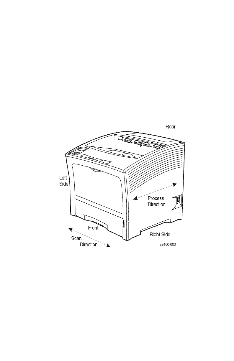
General Information
The Phaser 5400 Printer Service Guide is the primary document used for repairing
and maintaining the Phaser 5400 Laser Printer.
To ensure complete understanding of the product, participation in Xerox Phaser 5400
service training is recommended.
Machine Orientation
For servicing the Phaser 5400 Laser Printer, all references to machine orientation are
as illustrated below.
Figure 1 Machine Orientation
Process Direction = paper path
Phaser 5400 Laser Printer Service Guide 1
Page 31

Phaser 5400 Laser Printer Overview
■ The Phaser 5400 Laser Printer is a 40-page-per-minute monochrome,
600x600 and 1200x1200 dpi laser printer that uses a data-modulated laser
beam, standard dry-ink Xerographic imaging process, and heat and pressure
fusing to place a computer-generated image onto the surface of a sheet of
paper.
■ The printer uses a semiconductor laser in the Laser Scanner (also called
Raster Output Scanner) to generate a 5 milliwatt infrared laser beam. Image
data sent from the host computer modulates the beam, creating a latent
image on the surface of the electrically charged xerographic drum inside the
Print Cartridge.
■ Also inside the Print Cartridge, electrically charged toner is applied to the
drum and it adheres to the latent image, developing it.
■ Paper is fed past the drum, and a bias transfer roller (BTR), behind the paper,
helps to transfer the toner from the drum to the paper.
■ The paper with dry toner statically adhered to it continues to the fuser where
heat and pressure melt and bond the toner to the paper, creating a dry,
permanent print.
The printer requires 110 VAC, 50/60 Hz (or optionally 220-240 VAC 50/60 Hz) using
1.1 kw for warm-up and approximately 890 watts for a print cycle. Power saver mode
reduces power consumption to below 45 W to comply with ENERGY STAR
requirements.
■ Safety interlocks within the printer remove power to the Laser Scanner
(ROS), Fuser heat rod and motor drives whenever the Rear Cover or Top
Cover are opened and when the Print Cartridge is removed.
■ The Print Engine Controller Board controls all printer functions, houses
printer diagnostics and supporting test prints, stores operating parameters,
and signals printer errors.
■ The System Controller Board interfaces to host computer(s) via Ethernet,
USB or Parallel ports, processes PostScript or PCL print files into Image
Video data and transmits data and printing commands to the Print Engine
Controller Board.
■ The Phaser 5400 Laser Printer comes standard with one 500-Sheet
Letter-size tray, a 150 sheet MBF (Multi-sheet Bypass Feeder), and
500-Sheet output bin.
■ Four optional accessories are offered:
■ 500-Sheet Feeder Assembly (two versions, Letter-size or Ledger-size tray)
■ 2000-Sheet Feeder Assembly (for Letter size paper only)
■ Duplex Module
■ 1000-Sheet Stacker Bin (for Letter-size and smaller paper)
2 Phaser 5400 Laser Printer Service Guide
Page 32

■ The Customer-Replaceable Consumable consists of a Print Cartridge, rated
at 20,000 pages at 5% coverage. The printer signals “Toner Low” when
2% - 3% toner is remaining. A front panel setting selects whether the user
may continue printing (Toner Low = Continue) or must stop and change the
cartridge (Toner Low = Stop).
■ A Maintenance Kit, also a Customer-Replaceable Consumable and normally
purchased and installed by the customer regardless of Warranty or Contract
entitlement, consists of two items rated for replacement at 200,000 Letter
size pages.
■ Bias Transfer Roller (BTR)
■ Fuser
■ The printer’s Maintenance Kit counter signals on the front panel when the
Maintenance Kit should be replaced. This is a soft error, “Printing may
continue regardless of the Maintenance Kit count, but image quality may be
compromised.” After installing these items, the Maintenance Kit counter
must be manually reset.
Phaser 5400 Laser Printer Service Guide 3
Page 33

Parts of the Printer
Printer Components
The base printer contains the following major components:
Front view
1 Standard Output Bin
2 Paper Guide / Curl Extension
3 Control Panel
4 Paper Support and Stopper
5 Multi-sheet Bypass Feeder (closed)
6 Tray 1
7 Paper Amount Indicator
8 Power Switch
1
2
3
4
5
6
7
Figure 2 Front View
Rear view
9 Rear Cover (closed)
10 Power Cord Receptacle
11 LVPS Fan Ventilation Slots
12 Interface Connectors
(Parallel, USB, Ethernet)
13 Top cover (closed)
8
S5400-03-A
13
9
10
11
12
Figure 3 Rear View
S5400-04-A
4 Phaser 5400 Laser Printer Service Guide
Page 34

Printer Options
Front view
1 1,000-Sheet (High Capacity) Stacker
Bin
2 500-Sheet Feeder
(A4/Letter Tray, shown as Tray 1,
A3/Ledger Tray, shown as Tray 2 in
the 500-sheet Feeder)
3 2,000-Sheet Feeder (shown as Tray 3)
1
2
3
Rear view
4 Optional Duplex Module (installed)
5 Optional Hard Drive (installed)
6 Optional Memory DIMMs (installed)
S5400-05-A
Figure 4 View from Right Front
4
6
5
Figure 5 View from Left Rear
S5400-06-A
Phaser 5400 Laser Printer Service Guide 5
Page 35

Control Panel
The Xerox Phaser 5400 Printer Control Panel:
■ Displays printer status and jobs in process.
■ Provides the means to change printer settings.
■ Allows you to print reports (such as the configuration sheet, which lists the
printer’s current settings)
1
2
3
S5400-07-A
Figure 6 Control Panel
1 Display screen
2 Four indicator LEDs:
■ Online indicator LED
■ Form Feed indicator LED
■ Fault indicator LED
■ Data indicator LED
3 Eight control panel keys
■ Online key [0]
■ Enter key [4]
■ Menu Up key [1]
■ Menu Down key [5]
■ Item Up key [2]
■ Item Down key [6]
■ Value Up key [3]
■ Value Down key [7]
6 Phaser 5400 Laser Printer Service Guide
Page 36

Display Screen
The control panel’s display screen:
■ Provides access to a hierarchy of menus to configure and control the printer.
Access the menus by pressing the Menu keys (labeled 1 or 5). For more
information on the menu structure, refer to the Advanced Features and
Troubleshooting Manual.
■ Displays information about the status of the printer (or the job in process):
Examples:
■ The printer is online and ready to accept print jobs:
Ready..
■ The printer is processing data:
Processing..
■ The printer is waiting for more data:
Waiting...
■ The printer is low on toner:
Toner Low
■ A tray is empty (in this case, Tray 2 is empty and no longer is being used to
print):
Tray 2 Empty
■ There is a problem (in this case, a paper jam has occurred while feeding from
Tray 3):
Tray 3 JamOpen Tray 3
Phaser 5400 Laser Printer Service Guide 7
Page 37

Rear Panel
Ethernet
CR1
View Port
USB
Parallel
LEFT
REAR
s5400-344
Figure 7 Rear Panel
8 Phaser 5400 Laser Printer Service Guide
Page 38

Print Engine Assemblies
Figure 8 Print Engine Assemblies, Sensors and Interlock Locations 1 Tray 1 and MBF Paper Path Components 1
In the above figure, all of the identified items are contained in the following four
FRUs:
■ Laser Scanner: stand-alone unit
■ Print Cartridge contains:
■ Bias Charge Roller
■ Cleaning Blade
■ Drum
■ Detack Saw
■ Mag Roller
■ CM Blade
■ Fuser contains:
■ Heat Roller
■ Pressure Roller
■ Bias Transfer Roller: stand-alone unit
Phaser 5400 Laser Printer Service Guide 9
Page 39

Figure 9 FRU Assemblies, Sensors and Interlock Locations 2
10 Phaser 5400 Laser Printer Service Guide
Page 40

Figure 10 FRU Assemblies, Sensors and Interlock Locations 3 - Detack
Saw, Registration & Bias Transfer Rollers and Paper Transport Assembly
Phaser 5400 Laser Printer Service Guide 11
Page 41

Full Stack Sensor
Figure 11 FRU Assemblies, Sensors and Interlock Locations 4 - Fuser
Area
12 Phaser 5400 Laser Printer Service Guide
Page 42

Figure 12 FRU Assemblies, Sensors and Interlock Locations 5 - Main
Drive
Phaser 5400 Laser Printer Service Guide 13
Page 43

Figure 13 FRU Assemblies, Sensors and Interlock Locations 6 - FRU
Circuit Assemblies
14 Phaser 5400 Laser Printer Service Guide
Page 44

Paper Path Information
Paper is fed from the Tray or the Multi-sheet Bypass Feeder (MBF) and transported
through the printer to the exit along the paper path shown in the following figure.
Figure 14 Paper Path Flow
Phaser 5400 Laser Printer Service Guide 15
Page 45

The figure below is a cut-away side view of the Phaser 5400 Laser Printer that shows
the paper paths and the major components directly related to the paper transportation.
Figure 15 Paper Path Components
16 Phaser 5400 Laser Printer Service Guide
Page 46

Printer Specifications
RAM and Printer Capabilities
The Phaser 5400 Laser Printer is equipped with 32 Mbytes of RAM and is expandable
as shown below. Installing additional RAM:
■ Improves system performance.
■ Improves processing of complex jobs.
■ Enables increased graphics at higher resolutions.
■ Improves collation printing.
Memory Expansion
The base printer contains 32 MB of DRAM installed as a standard. Three option slots
are provided on the System Controller Board to accommodate DIMMs per the
Memory Expansion Options table below. The maximum DRAM memory, both
on-board and added via DIMMs is 192 MB. Memory added beyond this limit is
ignored.
Additional memory provides the following enhanced printer capabilities:
■ Additional font cache
■ Additional download space for fonts, macros and images
■ Increased throughput for complex pages, duplex pages and larger paper sizes
(A3 / Ledger)
■ Increased PostScript VM (virtual memory)
■ Collated sets without the Hard Disk Drive
Note: The printer features three DIMM slots (J4, J5 and J6) for
memory expansion. DRAM DIMMs can be installed in any of
these slots. Refer to the instructions packed with the DIMMs.
You can increase the resident fonts of the printer or create resident macros by
installing a Flash DIMM or hard drive and downloading resources permanently to this
memory. If flash memory is to be used, the 8 MB Flash DIMM can be installed in any
slot (J4, J5 or J6). If a bootable flash DIMM is installed, it must be in J6 slot;
however, this is not a standard option and is not likely to be seen unless a custom
version of the printer were produced.
Table 1 Memory Upgrades
Memory Upgrades Part Number
16-Mbyte DIMM 097S02356
32-Mbyte DIMM 097S02357
64-Mbyte DIMM 097S02358
8-Mbyte Flash DIMM 097S02360
Phaser 5400 Laser Printer Service Guide 17
Page 47

Basic Specifications
Table 2 Basic Specifications
Category Specification
Standard configuration Print engine, MBF, 500-sheet Paper Feeder, A4/Letter Cassette
Printing method Xerography
Exposing method Scanning with a semiconductor laser beam
Laser light source Laser Diode (Nominal maximum output: 10 mW)
Print image resolution Fixed-resolution version: 600 or 1200 dpi
Fusing method Applying heat and pressure with rolls
Warm-up time Within 60 seconds from a cold start after power (nominal 120 V,
Ranges of paper sizes A6 Card stock to Tabloid Extra (see Table 9 and Table 10 for
Printable area The print quality is not guaranteed in a 4 mm border from all edges
Paper capacity 650 sheets to 3150 sheets, depending on options.
Output Tray capacity About 500 printed sheets standard; plus 1000 Letter size or smaller
(500-sheet universal paper cassette), Print Cartridge
220 V) is switched on.(Measured at 72° F (22° C) ambient
temperature with the specified voltage)
details).
in the printable area.
sheets in the optional Stacker.
Electrical Specifications
Table 3 Electrical Specifications
AC Power Required 120 V Version: 120 VAC (90 ~ 140 V), 50/60 Hz (47 ~ 63 Hz),
Max. Power Required
(during warm-up)
Power Consumption,
Printing
220 VAC Version: 220 VAC (198 ~ 264 V), 50/60 Hz (47 ~ 63 Hz)
110-127 VAC rated consumption max: 1.2 kw electrical current max
11A
220-240 VAC rated consumption max: 1.3 kw electrical current max
5.5 A
890 watts/3,045 BTU/hr.
18 Phaser 5400 Laser Printer Service Guide
Page 48

Mechanical Specifications
Table 4 Physical Dimensions
Height
cm / in.
Phaser 5400 printer only 39.5 / 15.6 49.0 / 19.3 46.0 / 18.1 27 / 60
500-Sheet Feeder
A4 Letter size
500-Sheet Feeder
A3 Ledger size
2000-Sheet Feeder 41.0 / 16.1 49.0 / 19.3 50.9 / 20.0 23 / 51
1000-Sheet Stacker 35.5 / 14.0 49.0 / 19.3 32.0 / 12.6 5 / 11
13.4 / 5.3 50.1 / 19.7 43.9 / 17.3 9.5 / 21
13.4 / 5.3 50.1 / 19.7 58.9 / 23.2 10.5 / 23
Table 5 Printer Clearances
Location Clearance (cm / in.)
Front 76 / 30
Rear 30 / 12
Left Side 20 / 8
Right Side 10 / 4
Mounting Surface Level within 5°
Width
cm / in.
Depth
cm / in.
Weight
kg / lb.
Phaser 5400 Laser Printer Service Guide 19
Page 49

Environmental Specifications
Table 6 Environmental Specifications
Environmental
conditions for installation
(Printer unpacked and
having the Print
Cartridge installed)
Environmental
conditions for storage of
a printer packed for
shipping
Environmental
conditions for storage of
the Print Cartridge in the
packed condition
Noise generation Printing: 58.1 dB (A)
Dust generation 0.1 mg/m
Ozone generation 0.02 ppm or less in Time Weighted Average (TWA)
Illumination Under 3000 Lux (Direct sunlight must be avoided)
Operating: 41 – 95° F (5 – 35° C) 15 – 85% RH (Without
condensation) 0 – 3000 m above sea level Horizontal bias within 5°
of level.
Non-operating: -68 – 104° F (-20 – 40° C) 5 – 85% RH (Without
condensation) 0 – 3000 m above sea level
When the Print Cartridge is packed together:
• Normal conditions (Assured period: 12 months) 32 – 95° F
(0 – 35° C) 15 – 80% RH (Without condensation)
• Severe conditions (Assured period: 1 month) -68 – 32° or
95 – 104° F (-20 – 0° or 35 – 40° C) 5 –15 or 80 – 95% RH (Without
condensation)
When the Print Cartridge is not packed together:
• Normal conditions (Assured period: 12 months) -68 – 122° F
(-20 – 50° C) 5 – 85% RH (Without condensation)
• Severe conditions (Assured period: 48 hours) 122 – 140° F
(50 – 60° C) 85 – 95% RH (Without condensation)
• The assured altitude is 0 – 3000 m above sea level.
When transported by air in a cargo room pressurized over
70.93 kPa, the assured altitude is 0 – 15000 m.
• Normal conditions (Assured period: 24 months) 32 – 95° F
(0 – 35° C) 15 – 80% RH (Without condensation)
• Severe conditions (Assured period: 1 month) -68 – 32° or
95 – 104° F (-20 – 0° or 35 – 40° C) 5 –15 or 80 – 95% RH (Without
condensation)
The assured altitude is 0 – 3000 m above sea level.
When transported by air in a cargo room pressurized over
70.93 kPa, the assured altitude is 0 – 15000 m.
The unpacked Print Cartridge remains intact for 12 months in the
above non-operating environmental conditions for the printer.
Stand by: 31.4 dB (A)
Impulse: 63.5 dB (A)
3
or less
20 Phaser 5400 Laser Printer Service Guide
Page 50

Life Expectancies
Table 7 Life Expectancies of the Print Engine and Options
Life of HCS Either 600,000 prints or 5 years.
Life of Duplex Module Either 600,000 prints or 5 years whichever comes first.
Life of Printer Engine Either 600,000 prints on Letter size paper (LEF) or 5 years whichever
Life of Paper Feeder 600K for each: 500-Sheet and 2000-Sheet feeders
Life of Print Cartridge 20,000 prints (average) The life of the Print Cartridge is defined as the
Maintenance Kit 200,000 prints
comes earlier. A double-sided print is counted as two prints.
number of prints which satisfy the specified print quality without
shaking the Print Cartridge when consecutively printing on A4/Letter
size sheets (LEF) under the normal conditions with 5% image
coverage. A double-sided print is counted as two prints.
Conforming Regulations and Standards
Table 8 Conforming Regulations and Standards
Laser safety regulations 100 V / 120 V Version: US FDA 21 CFR, Sections 1010 & 1040,
EMI (Electromagnetic
Interference) regulations
Other safety regulations
and standards
Sub-chapter J, Chapter 1
220 V / 240 V Version: IEC825 Class I Laser Product
120 V Version (USA): FCC Part 15 subpart B, Class A (ANSI
C63.4/11.4D)
220 V / 240 V Version (EC):EN55022
(CISPR Publication 22), Class A
100 V / 120 V Version: UL 1950 3rd Edition CSA C22.2 No. 950-M95
220 V/ 240 V Version: IEC60950 2nd Edition CE Directive Nordic
Agency Approvals (NEMKO, SEMKO, SETI, and DEMKO)
Phaser 5400 Laser Printer Service Guide 21
Page 51

Printing Speed
Table 9 Printing Speed for the First Sheet Out
10.7 S: Simplex
D: Duplex
Ledger SEF S 5.66 6.06 6.83 7.61
D 10.90 11.29 11.60 12.71
A3 SEF S 5.59 5.99 6.76 7.54
D 10.45 10.88 11.59 12.45
Letter LEF S 4.41 4.81 5.58 6.36
D 8.25 8.62 9.36 10.20
A4 LEF S 4.38 4.78 5.55 6.32
D 8.05 8.57 9.16 10.16
Statement
LEF
S 3.974.375.145.92
D 7.257.678.339.13
The above chart does not include RIP time.
Note: RIP time is the time expended from when the printer gets the
command to print to where paper is started through the
printer.
Table 10 Consecutive Printing Speed after the First Sheet Out
600 dpi + 1200 Ledger SEF 19.0 14.0
image quality A3 SEF 19.0 14.0
True 1200 dpi Ledger SEF 9.5 7.0
Time Needed for Initial Print (sec)
MBF Tray 1 Tray 2 Tray 3
Paper Size Simplex Mode
(Prints per
min.)
Letter LEF 40.0 28.6
A4 LEF 40.0 28.6
A3 SEF 9.5 7.1
Letter LEF 20.0 14.1
A4 LEF 20.0 14.2
Duplex Mode
(Prints per
min.)
The above chart does not include RIP time.
22 Phaser 5400 Laser Printer Service Guide
Page 52

Printing Media Feeding Means
The Phaser 5400 Laser Printer has the following four print media feeding means:
1. Multi-sheet Bypass Feeder (Standard) 150 sheet capacity
2. A4/Letter Tray (Standard) 500 sheet capacity
3. A3/Ledger Tray (Optional) 500 sheet capacity
4. A4/Letter 2000-Sheet Feeder (Optional) 2000 sheet capacity
Note: All capacities assume a typical paper weight of 80 g/m
(20 lbs.). Capacities will differ with other weights.
Table 11 Supported Media and Media Sizes
Tray 1, Tray 2, Tray 3
Media Media Size A4/Letter A3/Ledger 2000-Sheet
A3 297 x 420 mm - SEF
(2)
A4 210 x 297 mm LEF LEF LEF LEF
A5 148 x 210 mm LEF
(2)
LEF
(2)
A6 105 x 148 mm ---LEF
B4-JIS 257 x 364 mm - SEF - SEF
B5-JIS 182 x 257 mm LEF
Statement 5.5 x 8.5 in. LEF
Executive 7.25 x 10.5 in. LEF
(2)
(3)
(3)
LEF
LEF
LEF
(2)
(3)
(3)
Letter 8.5 x 11 in. LEF LEF LEF LEF
Folio 8.5 x 13 in. - SEF - SEF
Legal 8.5 x 14 in. - SEF - SEF
-
-
-
-
LEF
LEF
LEF
LEF
(3)
(1)
(1)
(1)
(1)
Ledger 11 x 11 in. - SEF
Envelopes
COM-10
Monarch
DL
C5
Transparencies
A4
Letter
Labels
A4
Letter
4.1 x 9.5 in.
3.8 x 7.5 in.
110 x 220 mm
162 x 229
210 x 297 mm
8.5 x 11 in.
210 x 297 mm
8.5 x 11 in.
LEF
LEF
LEF
LEF
LEF
LEF
LEF
LEF
(1)(3)
(1)(3)
(1)(2)
(1)
(1)
(1)
(1)
(1)
Feeder
-SEF
-LEF
-LEF
-LEF
-LEF
-SEF
-
-
-
-
-
-
-
-
2
Multi-sheet
Bypass
Feeder
LEF
LEF
LEF
LEF
LEF
LEF
LEF
LEF
(1)
(1)
(1)
(1)
(1)
(1)
(1)
(1)
(1)
SEF = Short-Edge Feed, LEF = Long-Edge Feed
(1)
Simplex (one-sided) printing only.
(2)
Only when Defaults = Millimeters in the Control Panel System Menu.
(3)
Only when Defaults = Inches in the Control Panel System Menu.
Phaser 5400 Laser Printer Service Guide 23
Page 53

Table 12 Custom Paper Sizes
Tray 1, Tray 2, Tray 3
Acceptable
Sizes
Simplex
Width 148 - 297 mm
Length 98.4 - 216 mm
Duplex
Width 182 - 297 mm
Length 139.7 - 216 mm
A4/Letter
Tray
5.83 - 11.69 in.
3.875 - 8.5 in.
7.16 - 11.69 in.
5.5 - 8.5 in.
A3/Ledger
Tray
210 - 297 mm
8.27 - 11.69 in.
139.7 - 431.8 mm
5.5 - 17 in.
210 - 297 mm None 182 - 297 mm
139.7 - 431.8 mm None 139.7 - 341.8 mm
2000-Sheet
Feeder
None 76.2 - 305 mm
None 98.4 - 508 mm
Multi-sheet Bypass
Feeder
3 - 12 in.
3.875 - 20 in.
7.16 - 11.69 in.
5.5 - 17 in.
Printing Media
Table 13 Paper Weights
Acceptable Weights Input Source
60-200 g/m2 (16 lb. bond to 110 lbs. card stock) Main 500-Sheet Tray
60-135 g/m
60-105 g/m
2
(16 lb. bond to 36 lbs. bond) Multi-sheet Bypass Feeder
2
(16 lb. bond to 28 lbs. bond) Duplex Module
Storing Paper
■ Store the paper on a flat surface, in a relatively low-humidity environment.
■ Avoid storing paper in such a way as to cause wrinkling, bending, curling,
etc.
■ Do not unwrap paper until you are ready to use it, and rewrap any paper you
are not using.
■ Do not expose paper to direct sunlight or high humidity.
Optional 500-Sheet Feeders
2000-Sheet Feeder
24 Phaser 5400 Laser Printer Service Guide
Page 54

Unacceptable Media
The following media are unacceptable for use in the printer. Their use may cause high
rates of jamming and other paper-handling problems:
■ Excessively thick or thin paper
■ Heavily textured paper
■ Paper that has already been printed on (pre-printed Letterhead is allowed)
■ Wrinkled, torn, or bent paper
■ Moist or wet paper
■ Curled paper
■ Paper with an electrostatic charge
■ Glued paper
■ Paper with special coating
■ Paper unable to withstand a temperature of 150° C
(302° F)
■ Thermal paper
■ Carbon paper
■ Paper with paper fasteners, ribbons, staples, tape, etc. attached
■ Label stock with exposed backing sheet
Printing Accuracy
Table 14 Printing Accuracy
Item Accuracy Measuring
Registration Lead Edge 2.0 mm
Side Edge 2.5 mm
Skew 2.0 mm At a distance of 245 mm
Orthogonality 1.3 mm At a distance of 195 mm
In direction of paper travel 1.0 mm For 390 mm straight line
Linearity
Parallelism 2.0 mm Over 390 mm straight
Magnification
At right angle of direction of
paper travel
At 40 degree angle to
direction of paper travel
In direction of paper travel 100 0.8% At a distance of 390 mm
At right angle to direction of
paper travel
0.7 mm For 245 mm Straight line
1.5 mm For 347 mm straight line
100 0.5% At a distance of 245 mm
Phaser 5400 Laser Printer Service Guide 25
Conditions
lines
Page 55

Components to Be Replaced Periodically
Note: The Maintenance Kit is a user-installable consumable, not a
warranty item. It is supplied and installed by the customer at
regular intervals as indicated by the Control Panel. If Service
personnel supply this kit, the customer must be billed for it.
Table 15 Components to Be Replaced Periodically
Fuser Unit 200,000 prints (Letter LEF)
Bias Transfer Roll 200,000 prints (Letter LEF)
Options
The basic Phaser 5400 Laser Printer configuration consists of the base engine and a
Paper Feeder (Standard feeder) with a A4/Letter 500-sheet universal cassette. There
are various customer installed options available for the Phaser 5400 Laser Printer.
Table 16 Options
Option Description
A3/Ledger cassette (500-sheet universal
cassette)
A4/Letter cassette (500-sheet universal
cassette)
Duplex Module Makes duplex printing possible.
1000-Sheet Stacker Bin Stacks printed sheets, without offset.
A4/500-Sheet Feeder Installed as a second or third.
A3/500-Sheet Feeder Installed as a second or third.
Memory DIMMs See RAM and printer capabilities
Hard Drive
2000-Sheet Feeder Installed as the second or third paper high
Can hold regular size cut sheet up to the
A3/Ledger size.
Can hold regular size cut sheet up to the
A4/Letter size.
capacity feeders.
Note: Only one can be installed.
Part numbers and additional information for Maintenance items (fuser, BTR, etc.),
Consumables (printer cartridge, media, etc.) or Options, refer to Xerox Supplies and
Accessories on page 428 of this manual.
26 Phaser 5400 Laser Printer Service Guide
Page 56

Error Codes and Messages
Contents - Error Codes and Messages
RAP 1 Error Code C3: Insert Tray 1. . . . . . . . . . . . . . . . . . . . . . . . . . . . . . . . . . . . . . . . .42
RAP 2 Error Code C3: Insert Tray 2 Insert Tray 3 . . . . . . . . . . . . . . . . . . . . . . . . . . . . . .44
RAP 3 Error Code C3-2E: Tray 2 Failure Power Off / On Error Code C3-3E: Tray 3 Failure
RAP 4 Load MBF / Load Tray 1 / Load Tray 2 / Load Tray 3 . . . . . . . . . . . . . . . . . . . . . .48
RAP 5 Load Tray 2 / Load Tray 3 . . . . . . . . . . . . . . . . . . . . . . . . . . . . . . . . . . . . . . . . . . .50
RAP 6 Error Code C5: Remove Output From Std. Bin . . . . . . . . . . . . . . . . . . . . . . . . . . .52
RAP 7 Error Code C5: Remove Output From Stacker Bin . . . . . . . . . . . . . . . . . . . . . . . .55
RAP 8 Load Tray 2 / Load Tray 3 . . . . . . . . . . . . . . . . . . . . . . . . . . . . . . . . . . . . . . . . . . .58
RAP 9 Error Code E1-1: Paper Jam Open Top Cover . . . . . . . . . . . . . . . . . . . . . . . . . . .60
RAP 10 Error Code E2-1M: Paper Jam Open Top Cover Error Code E2-11: Tray 1 Jam
RAP 11 Error Code E2-12: Tray 2 Jam Open Tray 2 Error Code E2-13: Tray 3 Jam Open
RAP 12 Error Code E2-12: Tray 2 Jam Open Tray 2 Error Code E2-13: Tray 3 Jam Open
RAP 13 Error Code E2-D: Duplex Jam Open Rear Cover . . . . . . . . . . . . . . . . . . . . . . . .67
RAP 14 Error Code E3-1: Paper Jam / Open Top Cover . . . . . . . . . . . . . . . . . . . . . . . . .69
RAP 15 Error Code E4-0: Exit Jam Open Rear and Top Cover . . . . . . . . . . . . . . . . . . . .72
RAP 16 Error Code E5: Close Covers . . . . . . . . . . . . . . . . . . . . . . . . . . . . . . . . . . . . . . .74
RAP 17 Insert MBF. . . . . . . . . . . . . . . . . . . . . . . . . . . . . . . . . . . . . . . . . . . . . . . . . . . . . .76
RAP 18 Close Tray 2 Rear Door Close Tray 3 Rear Door . . . . . . . . . . . . . . . . . . . . . . . .78
RAP 19 Close Stacker Door . . . . . . . . . . . . . . . . . . . . . . . . . . . . . . . . . . . . . . . . . . . . . . .80
RAP 20 Error Code E7-1: Duplex Jam Open Rear Cover . . . . . . . . . . . . . . . . . . . . . . . .82
RAP 21 Error Code E8-1: Stacker Jam Open Rear Cover. . . . . . . . . . . . . . . . . . . . . . . .84
RAP 22 Error Code: E9-1 Duplex Unit Fail or Removed . . . . . . . . . . . . . . . . . . . . . . . . .86
RAP 23 Error Code E9-2: Stacker Bin Fail Power Off / On . . . . . . . . . . . . . . . . . . . . . . .88
RAP 24 Error Code E9-3: Tray 2 Failure Power Off / On Tray 3 Failure Power Off / On .89
RAP 25 Error Code J5: Toner Low . . . . . . . . . . . . . . . . . . . . . . . . . . . . . . . . . . . . . . . . . .90
RAP 26 Error Code J5: Toner Low . . . . . . . . . . . . . . . . . . . . . . . . . . . . . . . . . . . . . . . . . .91
RAP 27 Error Code J6-1: Replace Print Cartridge Install Print Cartridge. . . . . . . . . . . . .92
RAP 28 Error Code J8-1: Print Cartridge OEM ID Mismatch . . . . . . . . . . . . . . . . . . . . . .93
RAP 29 Error Code PSE-1: Paper Size Jam Open Rear Cover. . . . . . . . . . . . . . . . . . . .94
RAP 30 Error Code U1: Motor Failure Power Off / On . . . . . . . . . . . . . . . . . . . . . . . . . . .96
RAP 31 Error Code U2: Laser Failure Power Off / On . . . . . . . . . . . . . . . . . . . . . . . . . . .98
RAP 32 Error Code U4: Fuser Failure Power Off / On . . . . . . . . . . . . . . . . . . . . . . . . . .100
RAP 33 Error Code U5: Fan Failure Power Off Now . . . . . . . . . . . . . . . . . . . . . . . . . . .101
RAP 34 Error Code: 0101 - DIMM 1. . . . . . . . . . . . . . . . . . . . . . . . . . . . . . . . . . . . . . . .102
RAP 35 Error Code: 0102 - DIMM 2. . . . . . . . . . . . . . . . . . . . . . . . . . . . . . . . . . . . . . . .103
RAP 36 Error Code: 0103 - DIMM 3. . . . . . . . . . . . . . . . . . . . . . . . . . . . . . . . . . . . . . . .104
RAP 37 Error Code U6: IOT NVM Fail Power Off / On . . . . . . . . . . . . . . . . . . . . . . . . .105
Power Off / On . . . . . . . . . . . . . . . . . . . . . . . . . . . . . . . . . . . . . . . . . . . . . . . . . . .46
Open Tray 1. . . . . . . . . . . . . . . . . . . . . . . . . . . . . . . . . . . . . . . . . . . . . . . . . . . . .61
Tray 3. . . . . . . . . . . . . . . . . . . . . . . . . . . . . . . . . . . . . . . . . . . . . . . . . . . . . . . . . .63
Tray 3. . . . . . . . . . . . . . . . . . . . . . . . . . . . . . . . . . . . . . . . . . . . . . . . . . . . . . . . . .65
Phaser 5400 Laser Printer Service Guide 27
Page 57

Introduction
The Control Panel displays error information when sensors report problems with trays
or consumables, open covers, jams, system failures or other operating problems. Error
codes are usually specific: the word string or code has a special meaning, which
makes it important that service and users record errors exactly. Error codes are listed
in this section with Repair Analysis Procedures (RAPs) that outline corrective actions
that should resolve the error or conflict.
If an error is not visible on the Control Panel, fault history may be accessed one of
three ways:
1. Print (if possible) the Fault History from the Control Panel’s Print Menu.
2. View fault history in the Control Panel using Print Menu, Display Faults. When
the [3] key is pressed, the first fault will be displayed. Continue to press the [3] key
to view the entire fault history. It will read as follows:
Log Entry #1
<error code> <page count>
3. If the printer has a TCP/IP address and is connected to a network, view the
printer’s web page using a web browser. Enter the printer’s IP address as the URL.
Select the “Troubleshoot” link and fault history will be displayed.
To troubleshoot functional or performance problems (e.g. — failure to power up) and
print-quality problems, refer to Troubleshooting on page 107.
Error messages
The Control Panel displays error codes when it encounters certain system failures or
anomalies otherwise undetected by the user. These error codes are discussed in this
section. When an error code first occurs, cycle power on the printer to see if the error
recurs.
28 Phaser 5400 Laser Printer Service Guide
Page 58

Measurements
Power and signal grounds are connected to frame ground, therefore all circuit
troubleshooting can be performed using the metal frame (chassis) as the grounding
point. If more information is needed to locate connectors or test points, refer to
Plug/Jack Connector Locations on page 433.
Unless otherwise specified, the following voltage tolerances are used within this
section:
Table 17 Voltage Measurements
Stated Measured
+3.3 VDC +3.0 to 3.6 VDC
+5.0 VDC +4.8 to +5.2 VDC
+24.0 VDC +21.6 to +26.4 VDC
0.0 VDC Less than +0.5 VDC
Service Flowchart
Note: A Service Flowchart that outlines one possible approach to
troubleshooting and repair of the printer has been provided.
The Service Flowchart is an overview of the path a service
technician could
take, using this technical manual, to service
the printer engine and options.
To use the Service Flowchart, start at Block 1 to identify the problem. After you have
identified the problem, return to the Service Flowchart and proceed to Block 2 where
you inspect and clean the printer (a through cleaning frequently solves many printer
problems). You continue down the Flowchart in this manner, always returning to the
next block in the Service Flowchart after you have completed the tasks outlined in the
current block.
If you choose not to use the Service Flowchart, it is recommended that you start at the
appropriate Repair Analysis Procedure (RAP) Table and proceed from there.
Phaser 5400 Laser Printer Service Guide 29
Page 59

Identify the Problem
1. Verify that the reported problem does exist.
1
2. Check for any error codes and write them down.
3. Print three test prints.
4. Make note of any print quality problems in the test prints.
5. Make note of any mechanical or electrical abnormalities present.
6. Make note of any unusual noise or smell coming from the printer.
7. Print a Fault History (if the printer is able to print).
Inspect and Clean the Printer
1. Switch OFF printer power.
2. Disconnect the AC power cord from the wall outlet.
3. Remove the Toner Cartridge and shield it from strong light.
4. Inspect the printer interior and remove any foreign matter such as paper clips, staples,
pieces of paper, paper dust, or toner.
5. Clean the printer interior with a lint-free cloth, dampened slightly with cold water.
2
Do not use solvents or chemical cleaners to clean the printer interior.
Do not use any type of oil or lubricant on printer parts.
6. Clean all rubber rollers with a lint-free cloth that is dampened slightly with isopropyl alcohol
or cold water. Use a clean, dry, lint-free cloth to dry the rollers.
7. While you are cleaning, inspect the interior of the printer for damaged wires, loose
connections, toner leakage, and damaged or obviously worn parts.
8. If the Toner Cartridge appears obviously damaged, replace it with a new one.
Print
Find the Cause of the Problem
3
Use the Repair Analysis Procedure (RAP) Tables to find the cause of the problem.
Use Diagnostics to check printer and option components.
Use the Wiring Diagrams to locate Plugs/Jacks (P/Js) and test points.
Take voltage readings at various test points.
Correct the Problem
4
Use the Parts List to locate a part number.
Use the Removal and Replacement Procedures (RRPs) to replace a part.
Final Checkout
5
Figure 16 Service Flowchart
Test the printer to be sure you corrected the initial problem and there are no additional
problems present.
S5400-03
30 Phaser 5400 Laser Printer Service Guide
Page 60

Repair Analysis Procedure Table
If you used the Service Flowchart, it may have directed you to this section. Follow the
Repair Analysis Procedure Table located in this section to help you analyze your
printer problem.
How to Use a Repair Analysis Procedure Table
1. If you have an error code or error message displayed, refer to the Repair Analysis
Procedure in this section and locate the ERROR CODE in the “Error Code”
column or the “Error Message” in the “Displayed Error Message” column, then
go to the Repair Analysis Procedure indicated in the “Go To...” cell to the right of
the ERROR CODE.
2. If you have a printer operation problem, go to the PRINTER PERFORMANCE
area in the Troubleshooting Section of this manual.
3. If you have a print image problem, go to the IMAGE QUALITY area in the
Troubleshooting section of this manual.
4. Follow the Repair Analysis Procedure Table leading from the “Problem” cell to
the individual Primary Repair Analysis Procedure that corresponds to your error
code, printer operation problem, or print image problem.
5. Follow the instructions presented in the Repair Analysis Procedure.
6. If the Repair Analysis Procedure instructs you to perform a diagnostic test, refer to
Diagnostics area in the Tests and Adjustments Section of this manual.
7. Voltage and resistance values presented in the Repair Analysis Procedures are an
approximation. Actual readings may vary from the stated values.
8. Primary Repair Analysis Procedures may direct you to a Secondary Repair
Analysis Procedure.
Phaser 5400 Laser Printer Service Guide 31
Page 61

How to Follow a Repair Analysis Procedure
See the RAP Table example below.
1. Each numbered step in a Repair Analysis Procedure instructs you to perform a
certain action or procedure.
2. The Actions and Questions box may contain additional information and
numbered procedure steps you must follow to perform the action.
3. The action is followed by a question.
4. If your response to the question is Ye s, then follow the instructions for a Yes reply.
5. If your response to the question is No, then follow the instructions for a No reply.
6. Repair Analysis Procedures may ask you to take voltage readings at certain test
points within the printer. The Plug/Jack Connector Locations and Master Wiring
Diagram sections of this manual contain information on test point locations and
signal names.
7. Repair Analysis Procedures may ask you to run a specific diagnostic routine in
order to test a component or circuit. The Tests /Adjustments and Resetting NVRAM
sections of this manual contain information on printer diagnostics.
8. Repair Analysis Procedures often ask you to replace a printer component. The Key
FRU (Field Replaceable Unit) section of this manual provides detailed steps for
removing and replacing all major parts of the printer. If the component is not part
of the base engine, the Repair Analysis Procedure indicates which technical
manual contains the procedure.
RAP Table Example
Step Actions and Questions Yes No
2
NO PAPER SENSOR TEST
1. Enter Diagnostics.
2. From the Main Menu, select Component
Test / Sensor Input / press [4] to start, [0]
to stop.
3. Remove Tray 1 from the printer.
4. Manually actuate and deactuate Tray 1
No Paper Sensor.
Does the LCD counter increment each
time you press and release the
actuator?
Go to Step 3 Replace the No
Paper Sensor
Assembly
32 Phaser 5400 Laser Printer Service Guide
Page 62

General Notes on Using Repair Analysis Procedures
1. Unless indicated otherwise, the instruction “switch ON printer main power” means
for you to switch ON printer power and let the printer proceed through power-on
diagnostics and warm-up until it is on-line and ready to print.
2. Conventions used to represent connectors:
■ P/J XX means a Plug and its corresponding Jack are connected.
■ PXX means a Plug is disconnected. (Unless this plug is soldered to a board).
■ JXX means a Jack is disconnected. (Unless this jack is soldered to a board).
3. When you are instructed to take a voltage reading between “P/J A–B and P/J
X–Y”, place the red probe (+) of your meter on pin B of P/J A, and place the black
probe (–) of your meter on pin Y of P/J X.
4. When you are instructed to take voltage readings between “P/J X and P/J Y”
(without specified pin numbers), check all voltage carrying pins. Refer to the
Wiring Diagrams for signals and pin numbers.
5. When you are instructed to take a voltage reading, the black probe (–) is generally
connected to a pin that is either RTN (Return) or SG (Signal Ground). You can
substitute any RTN pin or test point in the printer, and you can use frame ground
(frame ground) in place of any SG pin or test point.
6. Unless a Repair Analysis Procedure instructs you otherwise; before measuring
voltages make sure the printer is switched ON, the Xerographic Cartridge and the
paper trays are in place, and all of the interlock switches are actuated.
7. All voltage values given in the Repair Analysis Procedures are approximate
values. Actual measured voltages may vary more than 25% from the values stated
in the Repair Analysis Procedures. The main purpose of most voltage readings
taken in the Repair Analysis Procedures is to determine whether or not a
component is receiving the correct voltage value from the power supply and if
gating (a voltage drop) occurs during component actuation. Gating signals may be
nothing more than a pulse, resulting in a momentary drop in voltage that may be
difficult or impossible to read on the average multi-meter.
8. Repair Analysis Procedures may instruct you to remove or replace a component.
Refer to the Key FRU Removal and Replacement Procedures section for
information on how to remove and reinstall a component.
9. When a Repair Analysis Procedure instructs you to replace a non-spared
component, and that component is part of a larger assembly, you should replace
the entire assembly.
Note: Repair Analysis Procedures assume there is no malfunction
Phaser 5400 Laser Printer Service Guide 33
in the System Controller Board. If you are unable to fix a
problem using the Repair Analysis Procedures, it is
recommended that you replace the System Controller board.
In some instances, the Control Panel Display may not be
sufficiently functional to accurately show error codes and/or
messages. Before replacing the System Controller, please
refer to the System Controller Error Blink Code Table on
page 222 to check the LED blink codes for additional help in
troubleshooting.
Page 63

Using Printer Diagnostics
Repair Analysis Procedures often ask you to enter Diagnostics and perform a specific
output test or input test. Diagnostics are built into the Print Engine Controller Board.
Use the Control Panel to access and run the various diagnostic routines that are
presented in this manual. Refer to Diagnostics, Test Prints, Service Tests and NVRAM
Adjustments on page 219 of this manual.
To Enter Diagnostics mode
When troubleshooting, you will encounter times when it is necessary to enter
Diagnostics mode. Please use the following procedure:
1. Make certain the printer is OFF.
2. Press and hold buttons [2] and [6] on the Control Panel while you switch printer
power ON. Continue holding until *IOT?* appears in the display (approximately
20 seconds).
3. When the Control Panel LCD displays *IOT?*, release buttons [2] and [6], then
press and hold button [4] until the LCD indicates you are in Diagnostics mode.
Note: You have 10 seconds to complete the transition from holding
4. When attempting to enter certain areas of Diagnostics, a password is required.
When so requested for password, sequentially press [0], [7], [3], [4] to gain entry.
Note: To exit Diagnostics, you must switch printer power OFF, wait
[2] and [6] to pressing [4]. If you miss this 10 second window,
the printer will complete a normal boot sequence, requiring
you to switch printer power OFF and start over.
20 - 30 seconds and switch printer power ON.
34 Phaser 5400 Laser Printer Service Guide
Page 64

Error Codes with Repair Analysis Procedure
Table 18 Error Code / Repair Analysis Procedure
Displayed
Error Message
Insert Tray 1
Insert Tray 2
Insert Tray 3
Tray 2 Failure
Power Off/On
Tray 3 Failure
Power Off/On
Load Tray 1
Load Tray 2
Load Tray 3
Load MBF
Fault
History
Log
C3-2E
C3-3E
Diagnostic Message /
Fault Description /
Comment
C3: Tray 1 Error
Tray 1 is not detected in printer. (All
paper size switches not actuated.)
C3: Tray 2 Error
Tray 2 is not detected in printer. (All
paper size switches not actuated.)
C3: Tray 3 Error
Tray 3 is not detected in printer. (All
paper size switches not actuated.)
C3-E3: HCF Elevator
1. 2000-Sheet Feeder elevator did not
reach home position within the
prescribed time.
2. Paper level sensor on when 2000Sheet Feeder Tray is opened.
C3-E3: HCF Elevator
1. 2000-Sheet Feeder elevator did not
reach home position within the
prescribed time.
2. Paper level sensor on when
2000-Sheet Feeder Tray is opened.
C5: Tray 1 Empty
Tray 1 is out of paper.
C5: Tray 2 Empty
Tray 2 is out of paper.
C5: Tray 3 Empty
Tray 3 is out of paper.
C5: MBF Empty
MBF is out of paper.
Action
Install Tray 1
Go to RAP 1, page 42.
Install Tray 2
500-Sheet Feeder
Go to RAP 2, page 44.
Install Tray 3
500-Sheet Feeder
Go to RAP 2, page 44.
Open and close
2000-Sheet Feeder
paper tray.
Go to RAP 3, page 46.
Open and close
2000-Sheet Feeder
paper tray.
Go to RAP 3, page 46
Load paper into Tray 1
Go to RAP 4, page 48
Load paper into Tray 2
Go to RAP 4, page 48
500-Sheet Feeder
Go to RAP 5, page 50
2000-Sheet Feeder
Go to RAP 8, page 58
500-Sheet Feeder
Go to RAP 5, page 50
2000-Sheet Feeder
Go to RAP 8, page 58
Load paper into MBF
Go to RAP 4, page 48
Phaser 5400 Laser Printer Service Guide 35
Page 65

Table 18 Error Code / Repair Analysis Procedure (cont'd.)
Displayed
Error Message
Remove Output
from Std. Bin
Remove Output
from Stacker Bin
Disk Error
Format Disk
Init Failed
Disk Locked
Format Failed
Disk Locked
Memory Failure
Power Off/On
NV Memory Fail
Power Off/On
Paper Jam
Open Top Cover
Open/Extend
MBF
Remove PrintCart
Clear Paper Path
Duplex Jam
Open Rear Cover
Clear Paper Path
Fault
History
Log
Diagnostic Message /
Fault Description /
Comment
C5: Top Tray Full
Top Tray is declared full when 5 prints
are delivered to the top tray after the
Full Stack sensor is actuated.
C5: HCS Tray Full
Five prints are delivered to the top tray
after the HCS Full Stack sensor is
actuated.
D-1 Hard Drive error was detected.
D-2 Cannot format disk, disk locked via
PJL or SNMP Command.
D-3 Cannot put disk in factory default
attempt to initialize disk after it is
locked.
ESS-M Controller memory has failed (32 MB
on board).
ESS-N Controller NVM Failure
E1-1
E1: Reg. Jam
1. Registration Sensor did not
deactuate within time after actuation
of Registration sensor.
2. Registration sensor is actuated at
power on.
3. Registration is actuated during
warm up cycle or an erase cycle.
E2-D
E2-2: Misfeed Jam
Registration Sensor did not actuate
within time after the actuation of the
Duplex Motor in reverse.
Action
Empty Top Tray.
Go to RAP 6, page 52.
Empty HCS Tray.
Go to RAP 7, page 55.
■ Power Off/On.
■ Format Hard Drive -
See Reset Menu
(RAP 68, page 172).
■ Replace Hard Drive.
■ Replace System
Controller Board
(RRP 8.1, page 305).
■ Customer Unlock
Disk.
■ Replace Hard Disk.
■ Customer Unlock
Disk.
■ Replace Hard Disk.
■ Power Off/On
■ Remove Options
■ Replace System
Controller PWB
(RRP 8.1, page 305).
■ Power Off/On
■ Replace System
Controller PWB
(RRP 8.1, page 305).
Open Top Cover,
remove EP Cartridge.
Open and Extend MBF
assembly and remove
any paper.
Go to RAP 9, page 60.
Open Rear Cover and
remove any paper.
Go to RAP 13,
page 67.
36 Phaser 5400 Laser Printer Service Guide
Page 66

Table 18 Error Code / Repair Analysis Procedure (cont'd.)
Displayed
Error Message
Paper Jam
Open Top Cover
Open /Extend
MBF
Remove All Paper
Tray 1 Jam
Open Tray 1
Open/Extend
MBF
Open Top Cover
Remove Print
Cart.
Clear Paper Path
Tray 2 Jam
Open Tray 2
Open/Extend
MBF
Open Top Cover
Remove PrintCart
Clear Paper Path
Tray 2 Jam
Open Tray 2
Open Rear
TrayDr
Clear Paper Path
Tray 3 Jam
Open Tray 3
Open/Extend
MBF
Open Top Cover
Remove PrintCart
Clear Paper Path
Fault
History
Log
E2-1M
E2-11
E2-12
E2-12
E2-13
Diagnostic Message /
Fault Description /
Comment
E2-1 Misfeed Jam
1. Simplex printing: Reg. Sensor is
OFF when the specified time has
passed timing from Feed Roll ON.
2. Printing from 2000-Sheet Feeder:
Reg. Sensor is OFF when the timing
is after receiving Feed Run status.
Comment: MBF misfeed
E2-1 Misfeed Jam
1. Simplex printing: Reg. Sensor is
OFF when the specified time has
passed timing from Feed Roll ON.
2. Printing from 2000-Sheet Feeder:
Reg. Sensor is OFF when the timing
is after receiving Feed Run status.
Comment: Tray 1 Misfeed
E2-1 Misfeed Jam
Simplex printing: Reg. Sensor is OFF
when the specified time has passed
timing from Feed Roll ON.
Comment: Tray 2 misfeed with
500-Sheet Feeder installed as Tray 2.
E2-1 Misfeed Jam
Simplex printing: Reg. Sensor is OFF
when the specified time has passed
timing from Feed Roll ON.
Printing from 2000-Sheet Feeder:
Reg. Sensor is OFF when the timing is
after receiving Feed_Run status.
Comment: Tray 2 misfeed with
2000-Sheet Feeder installed as
Tray 2.
E2-1 Misfeed Jam
Simplex printing: Reg. Sensor is OFF
when the specified time has passed
timing from Feed Roll ON.
Comment: Tray 3 Misfeed with
500-Sheet Feeder installed as Tray 3.
Action
Open Top Cover or
Feeder and remove
the sheets, then close
the cover.
Go to RAP 10,
page 61.
Open Top Cover of
Feeder and remove
the sheets, then close
the cover.
Go to RAP 10,
page 61.
Open Top Cover or
Feeder and remove
the sheets, then close
the cover.
Go to RAP 11,
page 63.
Open Top Cover or
Feeder and remove
the sheets, then close
the cover.
Go to RAP 12,
page 65.
Open Top Cover or
Feeder and remove
the sheets, then close
the cover.
Go to RAP 11,
page 63.
Phaser 5400 Laser Printer Service Guide 37
Page 67

Table 18 Error Code / Repair Analysis Procedure (cont'd.)
Displayed
Error Message
Tray 3 Jam
Open Tray 3
Open Rear
TrayDr
Clear Paper Path
Paper Jam
Open Top Cover
Remove Print
Cartridge
Clear Paper Path
Exit Jam-Open
Rear & Top Cover
Remove Print
Cartridge
Clear Paper Path
Close Stacker
Door
Close Tray 2
Rear Door
Close Tray 3
Rear Door
Close Covers
Insert MBF
Fault
History
Log
E2-13
E3-1
E4-0
Diagnostic Message /
Fault Description /
Comment
E2-1 Misfeed Jam
1. Simplex printing: Reg. Sensor is
OFF when the specified time has
passed timing from Feed Roll ON.
2. Printing from 2000-Sheet Feeder:
Reg. Sensor is OFF when the timing
is after receiving Feed_Run status.
Comment: Tray 3 misfeed with
2000-Sheet Feeder installed as
Tray 3 .
E3: Reg. Jam
Exit Sensor did not actuate within time
after the Registration clutch is
actuated.
E-4: Exit Jam
1. Exit Sensor is not deactuated within
time after it is actuated.
2. Exit Sensor is being actuated at
Power-Up.
3. Exit Sensor is ON when the interlock
is closed.
4. Exit Sensor turns from OFF to ON at
Erase Cycle.
E5: HCS Rear Door
HCS rear door interlock switch is
open.
E5: HCF Cover
2000-Sheet Feeder rear cover
interlock switch is open.
Comment: 2000-Sheet Feeder
installed as Tray 2.
E5: HCF Cover
2000-Sheet Feeder rear cover
interlock switch is open
Comment: 2000-Sheet Feeder
installed as Tray 3.
E5: Close Cover
1. Top cover interlock is open.
2. Rear cover interlock is open.
E5: MBF Extend
MBF Assy. is not closed.
Action
Open Top Cover or
Feeder and remove
the sheets, then close
the cover.
Go to RAP 12,
page 65.
Open Top Cover,
remove EP Cartridge
and remove any paper.
Go to RAP 14,
page 69.
Open Top Cover,
remove EP Cartridge
and remove any paper.
Go to RAP 15,
page 72.
Close HCS rear door.
Go to RAP 19,
page 80.
Close 2000-Sheet
feeder rear cover.
Go to RAP 18,
page 78.
Close 2000-Sheet
feeder rear cover.
Go to RAP 18,
page 78.
Close Top Cover.
Close Rear Cover.
Go to RAP 16,
page 74.
Close MBF.
Go to RAP 17,
page 76.
38 Phaser 5400 Laser Printer Service Guide
Page 68

Table 18 Error Code / Repair Analysis Procedure (cont'd.)
Displayed
Error Message
Duplex Jam
Open Rear Cover
Clear Paper Path
Stacker Jam
Open Rear Cover
Open Stacker
Door
Clear Paper Path
Duplex Unit Fail
or Removed
Stacker Bin Fail
Power Off/On
Tray 2 Failure
Power Off/On
Tray 3 Failure
Power Off/On
Install
Print Cartridge
Fault
History
Log
E7-1
E8-1
E9-1
E9-2
E9-3
E9-3
Diagnostic Message /
Fault Description /
Comment
E7: Duplex Jam
1. Duplex Sensor is not actuated within
the time after the start of the Duplex
drive motor in reverse.
2. Duplex Sensor is being actuated at
Power-Up.
3. Duplex Sensor is on when the
interlock is closed.
E8-1 HCS Jam
1. HCS Sensor did not actuate within
time after the actutation of the Exit
sensor.
2. HCS Sensor is not deactuated
within time after actuation of HCS
Sensor.
3. HCS Sensor is actuated at power
on.
Comment: Jam in the HCS
E9: Duplex Fail
Duplex module removed while power
is on.
E-9:
HCS removed while power is on.
E-9: HCF Fail
2000-Sheet Feeder removed while
power is on.
Comment: 2000-Sheet Feeder
installed as Tray 2.
E-9: HCF Fail
2000-Sheet Feeder removed while
power is on.
Comment: 2000-Sheet Feeder
installed as Tray 3.
J3: EP Cartridge
Print Cartridge is not installed.
Action
Open the Rear Cover
and remove any paper.
Go to RAP 20,
page 82.
Open HCS rear door
and remove any paper.
Open Rear cover and
remove any paper.
Go to RAP 21,
page 84.
Reinstall Duplex
Module
Go to RAP 22,
page 86.
Reinstall HCS
Go to RAP 23,
page 88.
Reinstall HCF
Go to RAP 24,
page 89.
Reinstall HCF
Go to RAP 24,
page 89.
Install the Print
Cartridge, or replace
with the correct Print
Cartridge.
Go to RAP 27,
page 92.
Phaser 5400 Laser Printer Service Guide 39
Page 69

Table 18 Error Code / Repair Analysis Procedure (cont'd.)
Displayed
Error Message
Toner Low J5
Replace Print
Cartridge
Print Cartridge
OEM ID
Mismatch
Paper Size Jam
Open Rear Cover
Motor Failure
Power Off/On
Laser Failure
Power Off/On
Fuser Failure
Power Off/On
Fault
History
Log
J6-1 Print Cartridge Life Expired Replace Print
J8-1 Print Cartridge ID Incorrect Install correct Print
PSE-1 Paper Size Error
U1
U2
U4
Diagnostic Message /
Fault Description /
Comment
J5: Toner Low
Toner Low is detected after 10 prints
while toner sensor is on.
There is a conflict between the size of
the paper, which is detected by the
Size Switches, and the length of paper
the printer detects by the length of
time the Registration Sensor is
actuated.
U1: Motor Fail
Motor Fail signal is declared 0.75
seconds after start of Main Motor.
U2: Laser Fail
1. Laser Signal intervals are longer
than the Ready time interval 20
seconds after the start of Laser
warm up.
2. The laser power does not reach the
value in NVM when the laser diode
is switched on after the start of Laser
warm up.
3. Laser signal intervals become
longer than the Fail time interval
after Laser warm up is completed.
U4: Fuser Fail
1. Fuser temperature drops below the
set temperature after the Fuser
warm up is complete.
2. Fuser warm up does not complete
within 110 seconds.
3. Thermistor circuit is detected to be
open.
4. Fuser temperature rises above the
set temperature.
5. Heat rod is on for 10 seconds when
the Main Drive Motor is stopped,
after the Fuser warm up is
completed.
Action
Replace Print
Cartridge.
Go to RAP 25,
page 90.
Go to RAP 26,
page 91.
Cartridge.
Go to RAP 27,
page 92.
Cartridge.
Go to RAP 28,
page 93.
Correct the mismatch.
Go to RAP 29,
page 94.
Power Off/On.
Go to RAP 30,
page 96.
Power Off/On.
Go to RAP 31,
page 98.
Power Off/On.
Go to RAP 32,
page 100.
40 Phaser 5400 Laser Printer Service Guide
Page 70

Table 18 Error Code / Repair Analysis Procedure (cont'd.)
Displayed
Error Message
Fan Failure
Power Off Now
IOT NVM Fail
Power Off/On
0101-DIMM 1 DIMM in slot J4 has failed. Go to RAP 34,
0101-DIMM 2 DIMM in slot J5 has failed. Go to RAP 35,
0101-DIMM 3 DIMM in slot J6 has failed. Go to RAP 36,
Fault
History
Log
U5
U6
Diagnostic Message /
Fault Description /
Comment
U5: Fan Fail
1. Fuser Fan has failed.
2. LVPS Fan has failed.
U6: NVM Fail
1. A read error is detected during
power on.
2. A write error is detected during write
to the Nonvolatile Memory.
Action
Check the Fuser Fan
and the LVPS Fan.
Power Off/On.
Go to RAP 33,
page 101.
Power Off/On.
Go to RAP 37,
page 105.
page 102.
page 103.
page 104.
Phaser 5400 Laser Printer Service Guide 41
Page 71

RAP 1 Error Code C3: Insert Tray 1
The Tray 1 Assembly is not in place.
Table 19 Error Code C3: Insert Tray Troubleshooting Procedure
Step Actions and Questions Yes No
1
REMOVE & REINSTALL TRAY 1
Completely remove and reinstall Tray.
Does the Insert Tray 1 message still appear?
2
PAPER STACK END GUIDE INSPECTION
Inspect the Paper Stack End Guide position in the tray.
Is the End Guide snug against the paper stack?
3
END GUIDE ADJUSTMENT
1. Adjust the End Guide to contact the paper stack.
2. Reinsert Tray and observe the Control Panel display.
Does adjusting the End Guide clear the Insert
Tray 1 message?
4
PAPER SIZE TEST
1. Enter Diagnostics Mode.
2. From the Main Menu, select Component Test / Tray 1
Size / press [4].
Does the paper size indicated on the LCD match
the paper size in Tray 1?
5
TRAY SIZE SENSOR TEST
1. Remove Tray 1.
2. Enter Diagnostics Mode.
3. From the Main Menu, select Component Test / Sensor
Input / press [4] to start the test.
4. Press and release each of the Tray 1 size sensor
actuators, while observing the LCD.
Does the LCD counter increment with each
actuation of a size sensor?
6
PAPER TRAY SIZE CAM INSPECTION
Inspect the size cam on the left side of the paper tray for
cracks or breakage and free rotation when the Paper
Tray End Guide is moved
Is the cam in good condition and does it rotate
freely when the Paper Tray End Guide is moved?
Go to
Step 2.
Go to
Step 4.
Problem
solved.
Replace
Print Engine
Controller
Board
[RRP 8.5,
page 310]. If
problem still
exists,
replace
System
Controller
Board
[RRP 8.1,
page 305].
Go to
Step 6.
Go to
Step 7.
Problem
solved.
Go to
Step 3.
Go to
Step 4.
Go to
Step 5.
Go to
RAP 54,
page 142.
Replace
Tray 1
[PL 2.1,
page 386 /
PL 2.2,
page 388].
42 Phaser 5400 Laser Printer Service Guide
Page 72

Table 19 Error Code C3: Insert Tray Troubleshooting Procedure (cont'd.)
Step Actions and Questions Yes No
7
OBSERVING PAPER SIZE ACTUATORS
1. Remove the Left Side Cover (RRP 1.1, page 250).
2. As you insert Tray 1, observe the size actuators
(visible under the Print Engine Controller Board metal
cover) move depending on the setting of Tray 1 [see
Table 20below].
Do the Tray 1 Size Cams contact the Paper Size
Actuators correctly for each size of paper?
8
SUSPECT COMPONENTS
The following printer components and areas are
associated with this specific problem. One or more of
these components or areas may have failed partially or
completely. If you cannot isolate this problem using the
steps in this Repair Analysis Procedure, replace each
component or troubleshoot each area listed below, one
at a time, until you isolate and solve the problem.
■ Wiring and connectors linking the components
■ Paper Tray and components
■ Print Engine Controller Board [RRP 8.5, page 310]
■ System Controller Board [RRP 8.1, page 305]
Replace the
Tray 1 Left
Guide
Assembly
[RRP 3.5,
page 277].
Replace
Tray 1
[PL 2.1,
page 386 /
PL 2.2,
page 388] If
still NO,
replace
Tray 1 Left
Guide
Assembly
[RRP 3.5,
page 277].
Table 20 Paper Size Actuators
8.5”
Actuator
4 Top X XXXX
3 XXX XX
2 XXX X
1 BottomXXXX
LEFA4LEFB5LEFA5LEF
14”
SEF
8.5”
SEFA4SEFB4SEF
Phaser 5400 Laser Printer Service Guide 43
Page 73

RAP 2 Error Code C3: Insert Tray 2
Insert Tray 3
Table 21 Error Code C3: Insert Tray 2 (or Tray 3) (500-Sheet Feeder)
.
Troubleshooting Procedure
Step Actions and Questions Yes No
1
REMOVE & REINSTALL TRAY 2/3
Remove and reinstall the paper tray.
Go to
Step 2.
Does the Insert Tray 2/3 still appear?
2
PAPER STACK END GUIDE INSPECTION
Inspect the Paper Stack End Guide position in the tray.
Go to
Step 3.
Is the End Guide snug against the paper stack?
3
PAPER SIZE CHECK
1. Enter Diagnostics mode.
2. From the Main Menu, select Component Test / Tray 2
Size (or Tray 3 Size) / press [4].
Does the paper size indicated on the LCD match
the paper size actually in Tray 2 (or Tray 3)?
4
PAPER SIZE SENSOR TEST
1. Remove the paper tray.
2. Scroll to Sensor Input / press [4].
3. One at a time, press and release each of the size
actuators for the problem tray.
Replace the
Print Engine
Controller
Board
[RRP 8.5,
page 310].
Go to
Step 5.
Does the LCD counter increment each time you
press and release one of the actuators?
5
SIZE CAM INSPECTION
Inspect the Size Cam on the left side of the Paper Tray.
Go to
Step 6.
Are the cams in good condition (not broken or
damaged) and rotate freely as the paper tray end
guide is moved?
6
LEFT GUIDE ASSEMBLY
1. Remove the 500-Sheet Feeder Left Cover [RRP 11.3,
page 330].
2. As you insert the paper tray, watch the size actuators
move depending on the setting of paper tray. See
Table 2 below.
Replace the
Tray 2/3 Left
Guide
Assembly
[RRP 11.13,
page 340].
Do the Tray 2/3 size cams contact the Paper Size
Actuators correctly for each size of paper?
Problem
solved.
Adjust the
position of
the End
Guide.
Go to
Step 4.
Go to
RAP 54
(Size
Switch),
page 142.
Replace
Tray 1
[PL 2.1,
page 386 /
PL 2.2,
page 388].
Replace
Tray 1
[PL 2.1,
page 386 /
PL 2.2,
page 388].
If problem
persists,
replace the
Tray 2/3 Left
Guide
Assembly
[RRP 11.13,
page 340].
44 Phaser 5400 Laser Printer Service Guide
Page 74

Table 21 Error Code C3: Insert Tray 2 (or Tray 3) (500-Sheet Feeder)
Troubleshooting Procedure (cont'd.)
Step Actions and Questions Yes No
7
SUSPECT COMPONENTS
The following printer components and areas are
associated with this specific problem. One or more of
these components or areas may have failed partially or
completely. If you cannot isolate this problem using the
steps in this Repair Analysis Procedure, replace each
component or troubleshoot each area listed below, one
at a time, until you isolate and solve the problem.
■ Print Engine Controller Board [RRP 8.5, page 310]
■ Tray 2/3 [PL 2.1, page 386; PL 2.2, page 388]
■ Left Guide Assembly [RRP 11.13, page 340]
Table 22 Paper Size Actuators
8.5"
Actuator
4 Top X XXXX
3 XXX XX
2 XXX X
1 BottomXXXX
LEFA4LEFB5LEFA5LEF
14"
SEF
8.5"
SEFA4SEFB4SEF
Phaser 5400 Laser Printer Service Guide 45
Page 75

RAP 3 Error Code C3-2E: Tray 2 Failure
Power Off / On
Error Code C3-3E: Tray 3 Failure
Power Off / On
The 2000-Sheet Feeder Tray Assembly has not been set.
Table 23 Error Code C3: 2000-Sheet Feeder Carriage Not In Position Message
Troubleshooting Procedure
Step Actions and Questions Yes No
1
PROCEDURE
Open and close the 2000-Sheet Feeder Tray Assembly.
Does the Insert Tray 2/3 message still appear?
2
STOPPER LINK
1. Open the 2000-Sheet Feeder Tray Assembly.
2. Manually push the actuator of the Stopper Link
[RRP 12.17, page 369].
3. Make certain the front side of the Nudger Support
Assembly lowers each time you press the Stopper
Link.
Does the Nudger Support Assembly lower each
time you press the Stopper Link?
3
STOPPER LINK
1. Enter Diagnostics mode.
2. From the Main Menu, select Component Test / Sensor
Input / press [4] to start, [0] to stop.
3. Manually push the actuator of the Stopper Link
[RRP 12.17, page 369].
Does the LCD counter increment each time you
press the Stopper Link?
4
“NO” FROM STEP 3 ABOVE
1. Switch printer power OFF.
2. Open the 2000-Sheet Feeder Tray Assembly.
3. Remove the Lower Rear Cover.
4. Disconnect P/J603 form the 2000-Sheet Feeder
Board.
5. Switch printer power ON.
6. Measure the voltage between P/J603-3 and frame
ground.
Does the voltage measure +3.2 VDC?
5
“NO” FROM STEP 4 ABOVE
Measure the voltage between P601-1 and frame
ground.
Does the voltage measure +3.2 VDC?
Go to
Step 2.
Go to
Step 3.
Replace the
Print Engine
Controller
Board
[RRP 8.5,
page 310].
Go to
Step 7.
Replace the
2000-Sheet
Feeder
Board
[RRP 12.8,
page 360].
Problem
solved.
Replace the
Stopper Link
[RRP 12.17,
page 369].
Go to
Step 4.
Go to
Step 5.
Go to
Step 6.
46 Phaser 5400 Laser Printer Service Guide
Page 76

Table 23 Error Code C3: 2000-Sheet Feeder Carriage Not In Position Message
Troubleshooting Procedure (cont'd.)
Step Actions and Questions Yes No
6
“NO” FROM STEP 5 ABOVE
Check for continuity between P/J13-1 and P601-1.
Is there continuity between the pins?
7
“YES” FROM STEP 4 ABOVE
1. Switch printer power OFF.
2. Reconnect P/J603 to the Feeder Board.
3. Switch printer power ON.
4. Measure the voltage between P/J603-3 and frame
ground.
5. Press and release the Stopper Link.
Replace the
Print Engine
Controller
Board
[RRP 8.5,
page 310].
Replace the
Print Engine
Controller
Board
[RRP 8.5,
page 310].
Replace the
2000-Sheet
Feeder
Harness
[PL 12.2,
page 420] or
Feeder
Harness
[PL 9.1,
page 404] as
necessary.
Replace the
Paper
Height
Sensor
[RRP 12.15,
page 367].
Does the voltage measure +3.2 VDC when the
link is released and 0.0 VDC when the link is
pressed?
8
SUSPECT COMPONENTS
The following printer components and areas are
associated with this specific problem. One or more of
these components or areas may have failed partially or
completely. If you cannot isolate this problem using the
steps in this Repair Analysis Procedure, replace each
component or troubleshoot each area listed below, one
at a time, until you isolate and solve the problem.
■ Stopper Link [RRP 12.17, page 369]
■ Print Engine Controller Board [RRP 8.5, page 310]
■ 2000-Sheet Feeder Board [RRP 12.8, page 360]
■ 2000-Sheet Feeder Harness [PL 12.2, page 420]
■ Feeder Harness [PL 9.1, page 404]
■ Paper Height Sensor [RRP 12.15, page 367]
■ Wiring and connectors linking the components
Phaser 5400 Laser Printer Service Guide 47
Page 77

RAP 4 Load MBF / Load Tray 1 / Load Tray 2 /
Load Tray 3
Logic Control on the Print Engine Controller Board detected a problem where a false
message to add paper to the MBF or a Paper Tray appears on the LCD.
Table 24 Add Paper to MBF, Tray 1, 2 or 3 Message Troubleshooting
Procedure
Step Actions and Questions Yes No
1
Does this problem appear only when using
Tra y 2 or Tr ay 3?
2
TRAY 1 PAPER LEVEL
Inspect the paper level in Tray.
Are there at least 100 sheets of paper in Tray 1?
3
MBF PAPER LEVEL
Inspect the paper level in the MBF.
Is there paper in the MBF?
4
MBF TRAY TEST PRINT
1. Enter Diagnostics mode.
2. From the Main Menu, select Test Print / Input Tray /
MBF / press [4] to select MBF as Input Tray.
3. From the Main Menu, select Test Print / Print Pattern /
press [4] to generate a test print.
Does the Load MBF message appear when you
feed paper from the MBF?
5
TRAY 1 TEST PRINT
1. Enter Diagnostics mode.
2. From the Main Menu, select Test Print / Input Tray /
Tray 1 / press [4] to select Tray 1 as Input Tray.
3. From the Main Menu, select Test Print / Print Pattern /
press [4] to generate a test print.
Does the Load Tray 1 message appear when you
feed paper from Tray 1?
6
BOTTOM PLATE INSPECTION
1. Remove Tray 1 from the printer.
2. Remove the Tray Cover, if installed, and all paper from
the tray.
3. Insert Tray into the printer and inspect the Bottom
Plate.
Is the bottom plate raised fully and evenly?
Go to
RAP 5,
page 50,
[500-Sheet
Feeder].
Go to
RAP 8,
page 58,
[2000-Sheet
Feeder].
Go to
Step 3.
Go to
Step 4.
Go to
Step 9.
Go to
Step 6.
Go to
Step 7.
Go to
Step 2.
Load paper
into Tray 1.
Load paper
into the
MBF.
Go to
Step 5.
Return to
Service Flow
Chart.
Replace the
Tray 1
Assembly
[PL 2.1,
page 386;
PL 2.2,
page 388].
48 Phaser 5400 Laser Printer Service Guide
Page 78

Table 24 Add Paper to MBF, Tray 1, 2 or 3 Message Troubleshooting
Procedure (cont'd.)
Step Actions and Questions Yes No
7
TRAY 1 NO PAPER & LOW PAPER SENSOR
ACTUATORS CHECK
1. Remove Tray 1.
2. Manually actuate the Tray 1 No Paper and Low Paper
sensor actuators.
Note: When checking the Low Paper Sensor using
the Sensor Test, at least one Paper Size
switch and the Low Paper Sensor must be
actuated.
Go to
Step 8 .
Do the No Paper and Low Paper Sensor
Actuators move smoothly?
8
TRAY 1 NO PAPER & LOW PAPER SENSORS
CHECK
1. Enter Diagnostics mode.
2. From the Main Menu, select Component Test / Sensor
Input / press [4] to start test, [0] to stop.
3. Manually actuate the Tray 1 No Paper and Low Paper
Sensors.
Replace the
Print Engine
Controller
Board
[RRP 8.5,
page 310].
Does the LCD counter increment each time you
actuate one of the actuators?
9
MBF NO PAPER SENSOR ACTUATOR CHECK
Insert, then remove a sheet of paper into the MBF.
Go to
Step 1 0.
Does the MBF No Paper Actuator move smoothly
when paper is inserted, then removed?
10
MBF NO PAPER SENSOR CHECK
1. Enter Diagnostics mode.
2. From the Main Menu, select Component Test / Sensor
Input / press [4] to start test, [0] to stop.
3. Insert, then remove a sheet of paper into the MBF
while observing the LCD.
Replace the
Print Engine
Controller
Board
[RRP 8.5,
page 310].
Does the LCD counter increment when you
insert, then remove the paper from the MBF?
11
SUSPECT COMPONENTS
The following printer components and areas are
associated with this specific problem. One or more of
these components or areas may have failed partially or
completely. If you cannot isolate this problem using the
steps in this Repair Analysis Procedure, replace each
component or troubleshoot each area listed below, one
at a time, until you isolate and solve the problem.
■ MBF Tray and components
■ Print Engine Controller Board [RRP 8.5, page 310]
■ Wiring and connectors linking the components
Replace the
Tray 1 No
Paper
Sensor
Actuator
[RRP 2.6,
page 266] or
Low Paper
Sensor
Actuator
[PL 3.1,
page 390].
Go to
RAP 43,
page 119
[Low Paper]
or RAP 53,
page 140
[No Paper].
Replace the
actuator.
Go to
RAP 51,
page 137.
Phaser 5400 Laser Printer Service Guide 49
Page 79

RAP 5 Load Tray 2 / Load Tray 3
Tray 2 or Tray 3 is out of paper.
Table 25 Add Paper To 500-Sheet Feeder
Troubleshooting Procedure
Step Actions and Questions Yes No
1
PAPER LEVEL
Check the paper level in the indicated Tray Assembly.
Is there paper in the indicated tray?
2
TRAY 2/3 BOTTOM PLATE
1. Remove the tray from the 500-Sheet Feeder
Assembly.
2. Remove the Tray Cover and all paper from the tray.
3. Insert the Tray into the 500-Sheet Feeder Assembly
and inspect the Bottom Plate.
Is the bottom plate raised?
3
NO PAPER SENSOR ACTUATOR
1. Remove the Paper Tray.
2. Manually actuate the No Paper Sensor Actuator.
Does the No Paper Sensor Actuator move
smoothly?
4
NO PAPER SENSOR
1. Enter Diagnostics mode.
2. From the Main Menu, select Component Test / Sensor
Input / press [4] to start, [0] to stop.
3. Press and release the No Paper Sensor Actuator.
Does the LCD counter increment when you press
and release the actuator?
5
“NO” FROM STEP 4 ABOVE
1. Switch printer power OFF.
2. Remove the 500-Sheet Feeder Left Cover [RRP 11.3,
page 330].
3. Disconnect P/J 133, and switch printer ON.
4. Measure the voltage between P133-4 and frame
ground, then between P133-6 and frame ground.
Do both voltages measure +3.2 VDC?
Go to
Step 2.
Go to
Step 3.
Go to
Step 4.
Replace the
Print Engine
Controller
Board
[RRP 8.5,
page 310].
Go to
Step 6.
Load paper
into the Tray.
Replace the
Tray [PL 2.1,
page 386 /
PL 2.2,
page 388].
Replace the
No Paper
Sensor
Actuator
[RRP 11.20,
page 350].
Go to
Step 5.
Check for
continuity
between
P/J133 &
P/J13A, then
between
P/J13A &
P/J134.
Repair or
replace as
necessary. If
the harness
checks OK,
replace the
No Paper
Sensor
[RRP 11.19,
page 348].
50 Phaser 5400 Laser Printer Service Guide
Page 80

Table 25 Add Paper To 500-Sheet Feeder
Troubleshooting Procedure (cont'd.)
Step Actions and Questions Yes No
6
“YES” FROM STEP 5 ABOVE
1. Switch printer power OFF.
2. Reconnect P/J133.
3. Switch printer power ON.
4. Measure the voltage between P/J133-6 and frame
ground as you actuate and deactuate the No Paper
Sensor.
Go to
Step 7 .
Does the voltage measure +3.2 VDC when
deactuated and 0.0 VDC when actuated?
7
“YES” FROM STEP 6 ABOVE
Measure the voltage between P/J132-7 and frame
ground as you actuate and deactuate the No Paper
Sensor.
Go to
Step 8 .
Does the voltage measure +0.9 VDC when
deactuated and +2.76 VDC when actuated?
8
“YES” FROM STEP 7 ABOVE
1. Switch printer power OFF.
2. Remove the printer Left Side Cover [RRP 1.1,
page 250] and the Print Engine Controller Board
Cover [RRP 8.5, page 310].
3. Switch printer power ON.
4. Measure the voltage between P/J13-7 and frame
ground as you actuate and deactuate the No Paper
Sensor.
Replace the
Print Engine
Controller
Board
[RRP 8.5,
page 310].
Does the voltage measure +0.9 VDC when
deactuated and +2.76 VDC when actuated?
9
SUSPECT COMPONENTS
The following printer components and areas are
associated with this specific problem. One or more of
these components or areas may have failed partially or
completely. If you cannot isolate this problem using the
steps in this Repair Analysis Procedure, replace each
component or troubleshoot each area listed below, one
at a time, until you isolate and solve the problem.
■ Feeder Board [RRP 11.7, page 334]
■ Print Engine Controller Board [RRP 8.5, page 310]
■ No Paper Sensor [RRP 11.19, page 348]
■ Paper Tray [PL 2.1, page 386 / PL 2.2, page 388]
■ Wiring and connectors linking the components
Replace the
Feeder
Board
[RRP 11.7,
page 334].
Replace the
Feeder
Board
[RRP 11.7,
page 334].
Check for
continuity
between
P/J132 &
P/J131, then
between
P/J131 &
P/J13.
Repair or
replace as
necessary.
Phaser 5400 Laser Printer Service Guide 51
Page 81

RAP 6 Error Code C5: Remove Output
From Std. Bin
Error code indicates the Standard Bin is full.
Table 26 Error Code C5: Standard Bin Full
Troubleshooting Procedure
Step Actions and Questions Yes No
1
STACK FULL SENSOR TEST
1. Enter Diagnostics mode.
2. From the Main Menu, select Component Test / Sensor
Input / press [4] to start, [0] to stop.
3. Actuate and deactuate the Stack Full Sensor Actuator.
Does the LCD counter increment each time you
press and release the actuator?
2
STACK FULL SENSOR ACTUATOR INSPECTION
Visually inspect the Stack Full Sensor Actuator.
Does the actuator move freely and appear to be
in good condition (not broken or damaged)?
3
“YES” FROM STEP 2 ABOVE
1. Switch printer power OFF.
2. Remove the Left Side Cover [RRP 1.1, page 250 and
the Print Engine Controller Board Cover [RRP 8.5,
page 310].
3. Disconnect P/J19 from the Print Engine Controller
Board.
4. Switch printer power ON.
5. Measure the voltage between P/J19-11 and frame
ground, then between P/J19-13 and frame ground.
Do both voltages measure +3.3 VDC?
4
“NO” FROM STEP 3 ABOVE
Measure the voltage between P/J16-4 and frame
ground.
Does the voltage measure +3.3 VDC?
It appears
the HCS
Stack Full
Sensor is
working
correctly. If a
problem
persists,
replace the
Print Engine
Controller
Board
[RRP 8.5,
page 310].
Go to
Step 3.
Go to
Step 5.
Replace the
Print Engine
Controller
Board
[RRP 8.5,
page 310].
Go to
Step 2.
Replace the
Stack Full
Sensor
Actuator
[RRP 5.4,
page 294].
Go to
Step 4.
Replace the
LVPS
[RRP 8.6,
page 312].
52 Phaser 5400 Laser Printer Service Guide
Page 82

Table 26 Error Code C5: Standard Bin Full
Troubleshooting Procedure (cont'd.)
Step Actions and Questions Yes No
5
“YES” FROM STEP 3 ABOVE
1. Switch printer power OFF.
2. Reconnect P/J19 to the Print Engine Controller Board.
3. Enter Diagnostics mode.
4. From the Main Menu, select Component Test / Sensor
Input / press [4] to start, [0] to stop.
5. On the Print Engine Controller Board, measure the
voltage between P/J19-13 and frame ground.
Replace the
Print Engine
Controller
Board
[RRP 8.5,
page 310].
Does the voltage measure +3.3 VDC between
P19-13 and frame ground when the Stack Full
Sensor is deactuated and 0.0 V when actuated?
6
“NO” FROM STEP 5 ABOVE
1. Switch printer power OFF.
2. Open the Rear Cover.
Go to
Step 9 .
3. Disconnect P/J527 (3-pin connector on HVPS Cover).
4. Switch printer power ON.
5. Measure the voltage between P/J527-3 and frame
ground, then between P/J527-1 and frame ground.
Do both voltages measure +3.3 VDC?
7
“NO” FROM STEP 6 ABOVE
1. Switch printer power OFF.
Go to
Step 8 .
2. Remove the HVPS Cover [RRP 8.2, page 307].
3. Check for continuity between P/J502 and P/J527 as
follows:
■ J527-1 and J502-1
■ J527-2 and J502-2
■ J527-3 and J502-3
Is there continuity between each of the pins?
8
“YES” FROM STEP 7 ABOVE
1. Disconnect P/J501 from the Duplex Interface Board
and P/J19 from the Print Engine Controller Board.
2. Check for continuity between P/J501 and P/J19 as
follows:
■ J501-1 and J19-13
■ J501-2 and J19-12
■ J501-3 and J19-11
Replace the
Duplex
Interface
Board
[RRP 8.3,
page 308].
Is there continuity between each of the pins?
9
“YES” FROM STEP 6 ABOVE
1. Switch printer power OFF.
2. Disconnect P/J507 from the Full Stack Sensor.
3. Check for continuity between P/J507 and P/J527 as
follows:
■ J507-1 and J527-3
■ J507-2 and J527-2
■ J507-3 and J527-1
Replace the
Full Stack
Sensor
[RRP 5.2,
page 289].
Is there continuity between each of the pins?
Go to
Step 6 .
Go to
Step 7 .
Repair or
replace the
harness
[PL 9.1,
page 404] as
necessary.
Repair or
replace the
Duplex
Interface
Harness, as
necessary
[PL 9.1,
page 404].
Repair or
replace the
Full Stack
Sensor
Harness
[PL 6.1,
page 398 as
necessary.
Phaser 5400 Laser Printer Service Guide 53
Page 83

Table 26 Error Code C5: Standard Bin Full
Troubleshooting Procedure (cont'd.)
Step Actions and Questions Yes No
10
SUSPECT COMPONENTS
The following printer components and areas are
associated with this specific problem. One or more of
these components or areas may have failed partially or
completely. If you cannot isolate this problem using the
steps in this Repair Analysis Procedure, replace each
component or troubleshoot each area listed below, one
at a time, until you isolate and solve the problem.
■ Stack Full Sensor Actuator [RRP 5.4, page 294]
■ Stack Full Sensor [RRP 5.2, page 289]
■ Print Engine Controller Board [RRP 8.5, page 310]
■ LVPS [RRP 8.6, page 312]
■ Duplex Interface Board [RRP 8.3, page 308]
■ Duplex Interface Harness [PL 9.1, page 404]
■ Stack Full Sensor Harness [PL 6.1, page 398]
■ Wiring and connectors linking the components
54 Phaser 5400 Laser Printer Service Guide
Page 84

RAP 7 Error Code C5: Remove Output
From Stacker Bin
Error code indicates the Stacker Bin is full.
Table 27 Error Code C5: Stacker Bin Full
Troubleshooting Procedure
Step Actions and Questions Yes No
1
STACK FULL SENSOR TEST
1. Enter Diagnostics mode.
2. From the Main Menu, select Component Test / Sensor
Input / press [4] to start, [0] to stop.
3. Actuate and deactuate the Stack Full Sensor Actuator.
Does the LCD counter increment each time you
press and release the actuator?
2
STACK FULL SENSOR INSPECTION
Visually inspect the Stack Full Sensor Actuator.
Does the actuator appear to be in good condition
(not broken or damaged) and does it move freely
when actuated?
3
“YES” FROM STEP 2 ABOVE
1. Switch printer power OFF.
2. Remove the Left Side Cover [RRP 1.1, page 250] and
the Print Engine Controller Board Cover [RRP 8.5,
page 310].
3. Disconnect P/J19 from the Print Engine Controller
Board.
4. Switch printer power ON.
5. ON the Print Engine Controller Board, measure the
voltage P19-11 and frame ground, then between
P19-13 and frame ground.
Do both voltages measure +3.3 VDC?
4
“NO” FROM STEP 3 ABOVE
Measure the voltage between P/J16-4 and frame
ground.
Does the voltage measure +3.3 VDC?
It appears
the Stack
Full Sensor
is working
correctly. If a
problem
persists,
replace the
Print Engine
Controller
Board
[RRP 8.5,
page 310].
Go to
Step 3 .
Go to
Step 5 .
Replace the
Print Engine
Controller
Board
[RRP 8.5,
page 310].
Go to
Step 2 .
Replace the
HCS Stack
Full Sensor
Actuator
[RRP 10.7
page 324].
Go to
Step 4 .
Replace the
LVP S
[RRP 8.6,
page 312].
Phaser 5400 Laser Printer Service Guide 55
Page 85

Table 27 Error Code C5: Stacker Bin Full
Troubleshooting Procedure (cont'd.)
Step Actions and Questions Yes No
5
“YES” FROM STEP 3 ABOVE
1. Switch printer power OFF.
2. Reconnect P/J19 to the Print Engine Controller Board.
3. Enter Diagnostics mode.
4. From the Main Menu, select Component Test / Sensor
Input / press [4] to start, [0] to stop.
5. ON the Print Engine Controller Board, measure the
voltage between P/J19-13 and frame ground while
actuating and deactuating the Stack Full Sensor
Actuator.
Replace the
Print Engine
Controller
Board
[RRP 8.5,
page 310].
Does the voltage measure +3.3 VDC when the
Stack Full Sensor is deactuated and 0.0 VDC
when actuated?
6
“NO” FROM STEP 5 ABOVE
1. Switch printer power OFF.
2. Open the Rear Cover.
3. Disconnect P/J527 (3-pin connector on HVPS Cover).
Go to
Step 9.
4. Switch printer power ON.
5. Measure the voltage between P/J527-3 and frame
ground, then between P/J527-1 and frame ground.
Do both voltages measure +3.3 VDC?
7
“NO” FROM STEP 6 ABOVE
1. Switch printer power OFF.
2. Remove the HVPS Cover [RRP 8.2, page 307].
Go to
Step 8.
3. Check for continuity between P/J502 and P/J527 as
follows:
■ J527-1 and J502-1
■ J527-2 and J502-2
■ J527-3 and J502-3
Is there continuity between the pins?
8
“YES” FROM STEP 7 ABOVE
1. Disconnect P/J501 from the Duplex Interface Board
and P/J19 form the Print Engine Controller Board.
2. Check for continuity between P/J501 and P/J19 as
follows:
■ J501-1 and J19-13
■ J501-2 and J19-12
■ J502-3 and J19-11
Replace the
Duplex
Interface
Board
[RRP 8.3,
page 308].
Is there continuity between each of the pins?
9
“YES” FROM STEP 6 ABOVE
1. Switch printer power OFF.
2. Disconnect P/J507 from the Stack Full Sensor.
3. Check for continuity between P/J507 and P/J526 as
follows:
■ J507-1 and J527-3
■ J507-2 and J527-2
■ J507-3 and J527-1
Replace the
HCS Stack
Full Sensor
[RRP 10.6,
page 323].
Is there continuity between the pins?
Go to
Step 6.
Go to
Step 7.
Repair or
replace the
HCS Stack
Full Sensor
Harness
[PL 6.1,
page 398],
as
necessary.
Repair or
replace the
Duplex
Interface
Harness
[PL 9.1,
page 404],
as
necessary.
Repair or
replace the
HCS Stack
Full Sensor
[RRP 10.6]
or the Stack
Full Sensor
Harness
[PL 10.2,
page 410],
as
necessary.
56 Phaser 5400 Laser Printer Service Guide
Page 86

Table 27 Error Code C5: Stacker Bin Full
Troubleshooting Procedure (cont'd.)
Step Actions and Questions Yes No
10
SUSPECT COMPONENTS
The following printer components and areas are
associated with this specific problem. One or more of
these components or areas may have failed partially or
completely. If you cannot isolate this problem using the
steps in this Repair Analysis Procedure, replace each
component or troubleshoot each area listed below, one
at a time, until you isolate and solve the problem.
■ HCS Stack Full Sensor Actuator [RRP 10.7, page 324]
■ HCS Stack Full Sensor [RRP 10.6, page 323]
■ Print Engine Controller Board [RRP 8.5, page 310]
■ LVPS [RRP 8.6, page 312]
■ Duplex Interface Board [RRP 8.3, page 308]
■ Stack Full Sensor Harness [PL 10.2, page 410]
Phaser 5400 Laser Printer Service Guide 57
Page 87

RAP 8 Load Tray 2 / Load Tray 3
The last sheet of paper was fed.
Table 28 Add Paper to 2000-Sheet Feeder
Troubleshooting Procedure
Step Actions and Questions Yes No
1
PROCEDURE
Open the 2000-Sheet Feeder paper tray.
Is there paper in the tray?
2
NO PAPER SENSOR ACTUATOR
1. Open the 2000-Sheet Feeder Tray Assembly.
2. Inspect the No Paper Sensor Actuator.
Is the actuator in good condition and does it
move freely?
3
NO PAPER SENSOR TEST
1. Enter Diagnostics mode.
2. From the Main Menu, select Component Test / Sensor
Input / press [4] to start, [0] to stop.
3. Manually push the No Paper Sensor Actuator up and
release.
Does the LCD counter increment each time you
press and release the No Paper Sensor
Actuator?
4
“NO” FROM STEP 3 ABOVE
1. Switch printer power OFF.
2. Open the 2000-Sheet Feeder Tray Assembly.
3. Remove the Lower Rear Cover.
4. Disconnect P/J602 from the 2000-Sheet Feeder
Board.
5. Switch printer power ON.
6. Measure the voltage between P/J602-3 and frame
ground.
Does the voltage measure +3.2 VDC?
5
“NO” FROM STEP 4 ABOVE
Measure the voltage between P601-1 and frame
ground.
Does the voltage measure +3.2 VDC?
6
“NO” FROM STEP 5 ABOVE
1. Switch printer power OFF.
2. Check for continuity between P/J13-1 and P601-1.
Is there continuity between the pins?
Go to
Step 2.
Go to
Step 3.
Replace the
Print Engine
Controller
Board
[RRP 8.5,
page 310].
Go to
Step 7.
Replace the
2000-Sheet
Feeder
Board
[RRP 12.8,
page 360].
Replace the
Print Engine
Controller
Board
[RRP 8.5,
page 310].
Add paper to
the tray and
close.
Replace the
No Paper
Sensor
Actuator
[RRP 12.19,
page 371].
Go to Step 4
Go to
Step 5.
Go to
Step 6.
Go to
Step 8.
58 Phaser 5400 Laser Printer Service Guide
Page 88

Table 28 Add Paper to 2000-Sheet Feeder
Troubleshooting Procedure (cont'd.)
Step Actions and Questions Yes No
7
“YES” FROM STEP 4 ABOVE
1. Switch printer OFF.
2. reconnect P/J602 to the Feeder Board.
3. Switch printer power ON.
4. Measure the voltage between P/J602-3 and frame
ground.
5. Press and release the No Paper Sensor Actuator.
Replace the
Print Engine
Controller
Board
[RRP 8.5,
page 310].
Does the voltage measure +3.2 VDC when the
actuator is released and 0.0 VDC when the
actuator is pressed?
8
SUSPECT COMPONENTS
The following printer components and areas are
associated with this specific problem. One or more of
these components or areas may have failed partially or
completely. If you cannot isolate this problem using the
steps in this Repair Analysis Procedure, replace each
component or troubleshoot each area listed below, one
at a time, until you isolate and solve the problem.
■ No Paper Sensor Actuator [RRP 12.19, page 371]
■ No Paper Sensor [RRP 12.18, page 370]
■ 2000-Sheet Feeder Board [RRP 12.8, page 360]
■ Print Engine Controller Board [RRP 8.5, page 310]
■ Wiring and connectors linking the components
Replace the
No Paper
Sensor
[RRP 12.18,
page 370].
Phaser 5400 Laser Printer Service Guide 59
Page 89

RAP 9 Error Code E1-1: Paper Jam
Open Top Cover
There is a paper jam between the Paper Tray / Paper Handler Assembly and the
Registration Sensor.
Table 29 Error Code E1-1: Paper Jam Tray to Registration
Troubleshooting Procedure
Step Actions and Questions Yes No
1
REGISTRATION SENSOR ACTUATOR
INSPECTION
Inspect the Registration Sensor Actuator.
Is there foreign material blocking the
Registration Sensor Actuator?
2
REGISTRATION SENSOR TEST
1. Enter Diagnostics mode.
2. From the Main Menu, select Component Test / Sensor
Input / press [4] to start test, [0] to stop.
3. Manually actuate the Registration Sensor Actuator
while observing the LCD.
Does the LCD counter increment each time you
actuate the Registration Sensor Actuator?
3
REGISTRATION CLUTCH TEST
1. From the Main Menu, select Component Test / Reg
Clutch / press [4] to test.
2. Listen for the Registration Clutch to actuate and
deactuate.
Did the Registration Clutch actuate & deactuate?
4
SUSPECT COMPONENTS
The following printer components and areas are
associated with this specific problem. One or more of
these components or areas may have failed partially or
completely. If you cannot isolate this problem using the
steps in this Repair Analysis Procedure, replace each
component or troubleshoot each area listed below, one
at a time, until you isolate and solve the problem.
■ Wiring and connectors linking the components
Print Engine Controller Board [RRP 8.5,
page 310].
Remove
foreign
material.
Replace the
Print Engine
Controller
Board
(RRP 8.5,
page 310].
Replace the
Print Engine
Controller
Board
(RRP 8.5,
page 310].
Go to
Step 2.
Go to
RAP 50,
page 135.
Go to
RAP 39,
page 112.
60 Phaser 5400 Laser Printer Service Guide
Page 90

RAP 10 Error Code E2-1M: Paper Jam
Open Top Cover
Error Code E2-11: Tray 1 Jam
Open Tray 1
There is a paper jam between the Tray 1 or MBF and the Registration Sensor.
Table 30 Error Code E2-1: Paper Jam Troubleshooting Procedure
Step Actions and Questions Yes No
1
TEST PRINTS
1. Enter Diagnostics mode.
2. From the Main Menu, select Test Print / Input Tray /
MBF, Tray 1, 2 or 3 / press [4] to select as Input Tray.
3. From the Main Menu, select Test Print / Print Pattern /
press [4] to generate a test print.
4. Run 10 test prints.
5. Repeat sub-steps 1~4 above for all paper feed trays
and run 10 test prints from each tray.
Does the problem appear only when feeding
from Tray 1?
2
Is the paper curled, damaged or damp?
3
Is the paper size within specifications?
4
MBF FEED ROLLERS CHECK
1. Open the MBF door.
2. Enter Diagnostics mode.
3. From the Main Menu, select Test Print / Input Tray /
MBF / press [4] to select MBF as Input Tray.
4. From the Main Menu, select Test Print / Print Pattern /
press [4] to generate a test print.
5. Observe the MBF Feed Rollers.
Do the MBF Feed Rollers rotate one complete
turn?
5
MBF GEAR AND SPRING INSPECTION
1. Remove the MBF Assembly [RRP 2.1, page 259].
2. Remove MBF Gear Cover and inspect the gears for
cracks, broken or missing teeth. Also, inspect the
return spring for the MBF Feed Roller Shaft Gear.
Are the MBF gears and spring OK?
6
MBF TRAY INSPECTION
1. Remove the MBF Assembly [RRP 2.1, page 259].
2. Inspect the paper tray for a broken, bent or missing
spring.
3. Check for a broken hinge pin, or anything that would
prevent the up and down movement of the paper tray.
Does the problem continue?
Go to
Step 7 .
Replace with
fresh, dry
paper.
Go to
Step 4 .
Go to
Step 6 .
Go to
RAP 57,
page 149.
Replace the
MBF
Assembly
[RRP 2.1,
page 259].
Go to
Step 2 .
Go to
Step 3 .
Replace with
paper within
size specs.
Go to
Step 5 .
Replace
defective
gears or
spring.
Phaser 5400 Laser Printer Service Guide 61
Page 91

Table 30 Error Code E2-1: Paper Jam Troubleshooting Procedure (cont'd.)
Step Actions and Questions Yes No
7
BOTTOM PLATE INSPECTION
1. Remove Tray 1 and remove all paper.
2. Open the printer Top Cover, remove the Print
Cartridge and extend the MBF to the paper load
position.
3. Insert the Tray Assembly into the printer and observe
the bottom plate.
Go to
Step 8.
Replace the
tray
assembly.
Is the bottom plate raised?
8
Tray 1 FEED ROLLER TEST
1. Close the MBF.
2. Reinstall the Print Cartridge.
3. Close the Top Cover.
4. Remove Tray 1.
5. Enter Diagnostics mode.
6. From the Main Menu, select Component Test / Main
Motor / press [4] to start test.
7. While the Main Motor is running, select Component
Test / Tray 1 Feed Sol / press [4] to test.
Note: It may be necessary to press [4] several times
to observe the rollers.
8. Observe the Tray 1 Feed Rollers.
Go to
Step 9.
Go to
Step 10.
Do the Feed Rollers rotate one complete
revolution?
9
RETARD CHUTE ASSEMBLY INSPECTION
1. Remove the Retard Chute Assembly [RRP 3.1,
page 273].
2. Inspect the retard holder and retard arm for damage.
Go to
RAP 55,
page 145.
Go to
Step 10.
Is the Retard Chute Assembly OK?
10
RETARD CHUTE / RETARD HOLDER
REPLACEMENT
Replace the Retard Chute Assembly [RRP 3.1,
page 273] or the Tray 1 Retard Holder Assembly
[RRP 2.11, page 272] as necessary.
Go to
RAP 56,
page 147.
Problem
solved.
Does the problem persist?
11
SUSPECT COMPONENTS
The following printer components and areas are
associated with this specific problem. One or more of
these components or areas may have failed partially or
completely. If you cannot isolate this problem using the
steps in this Repair Analysis Procedure, replace each
component or troubleshoot each area listed below, one
at a time, until you isolate and solve the problem.
■ Wiring and connectors linking the components
62 Phaser 5400 Laser Printer Service Guide
Page 92

RAP 11 Error Code E2-12: Tray 2 Jam
Open Tray 2
Error Code E2-13: Tray 3 Jam
Open Tray 3
There is a paper jam between a 500-Sheet Feeder Assembly and the Registration
Sensor.
Table 31 Paper Jam / Misfeed 500-Sheet Feeder
Troubleshooting Procedure
Step Actions and Questions Yes No
1
PROCEDURE
1. Remove all of the paper from the problem paper tray
and reinstall the paper tray.
2. Enter Diagnostics mode.
3. From the Main Menu, select Test Print / Input Tray /
scroll to the empty paper tray / press [4] to select.
4. Scroll to Print Pattern / press [4] to begin test prints, [0]
to stop.
Does the LCD display a C5 error code?
2
Is the paper curled, damaged or damp?
3
Is the paper size within specifications?
4
PROBLEM TRAY REPLACEMENT
1. Remove problem paper tray and install Tray 1 into the
problem feeder.
2. Enter Diagnostics mode.
3. From the Main Menu, select Test Print / Print Pattern /
press [4] to start test prints, [0] to stop.
4. Print approximately twenty prints from the problem
feeder.
Does the LCD display an E2-1 error code?
5
PROBLEM TRAY FEED ROLLER
1. Remove Tray 1 from problem feeder.
2. Enter Diagnostics mode.
3. From the Main Menu, select Component Test / Main
Motor / press [4] to start motor, [0] to stop.
4. Scroll to Tray 2 or Tray 3 Feed Sol / press [4].
5. Observe the problem tray feed rollers.
Do the feed rollers rotate one complete turn?
6
“NO” FROM STEP 5 ABOVE
1. Remove the Left Cover [RRP 11.3, page 330] of the
500-Sheet Feeder.
2. Enter Diagnostics mode.
3. From the Main Menu, select Component Test / Turn
Roll Clutch / press [4]
Is the Feeder Motor rotating?
Go to
Step 2 .
Replace with
fresh, dry
paper.
Go to
Step 4 .
Go to
Step 5 .
Go to
Step 7 .
Go to
Step 8 .
Go to
RAP 5,
page 50.
Go to
Step 3 .
Replace with
paper within
size specs.
Replace the
defective
Tray
Assembly.
[PL 2.1,
page 386 /
PL 2.2,
page 388].
Go to
Step 6 .
Go to
RAP 65,
page 167.
Phaser 5400 Laser Printer Service Guide 63
Page 93

Table 31 Paper Jam / Misfeed 500-Sheet Feeder
Troubleshooting Procedure (cont'd.)
Step Actions and Questions Yes No
7
TURN ROLLER SHAFT TEST
1. Open the rear door of the 500-Sheet Feeder.
2. Enter Diagnostics mode.
3. From the Main Menu, select Component Test / Turn
Roll Clutch / press [4] to start.
Go to
Step 9.
Is the Turn Roller Shaft rotating?
8
RETARD CHUTE ASSEMBLY
1. Remove the 500-Sheet Feeder Retard Chute
Assembly [RRP 11.13, page 340].
2. Inspect the retard holder and retard arm for damage.
Is the Retard Chute Assembly OK?
9
SUSPECT COMPONENTS
The following printer components and areas are
associated with this specific problem. One or more of
these components or areas may have failed partially or
completely. If you cannot isolate this problem using the
steps in this Repair Analysis Procedure, replace each
component or troubleshoot each area listed below, one
at a time, until you isolate and solve the problem.
■ Feed Tray Assembly [PL 2.1, page 386 / PL 2.2,
page 388]
■ 500-Sheet Feeder Feed Head [RRP 11.8, page 335]
■ Rear Chute Assembly [RRP 11.12, page 339]
Remove the
Rear Chute
Assembly
[RRP 11.12,
page 339].
Inspect the
Rear Chute
Assembly for
damaged,
missing or
broken Idler
Rollers and
Springs.
Remove the
500-Sheet
Feeder Feed
Head
Assembly
[RRP 11.8,
page 335]
and inspect
the gears.
Replace all
defective
parts
[PL 11.2,
page 414].
Replace the
Retard
Chute
Assembly
[RRP 11.12,
page 339].
64 Phaser 5400 Laser Printer Service Guide
Page 94

RAP 12 Error Code E2-12: Tray 2 Jam
Open Tray 2
Error Code E2-13: Tray 3 Jam
Open Tray 3
A paper jam has occurred in the 2000-Sheet Feeder.
Table 32 Error Code E2-1: Paper Jam / Misfeed 2000-Sheet Feeder
Troubleshooting Procedure
Step Actions and Questions Yes No
1
PROCEDURE
1. Open the 2000-Sheet Feeder Upper Rear Cover
Assembly.
2. Remove the Jammed paper.
3. Run a test print.
Does the error message still appear?
2
PAPER INSPECTION
1. Pull out the 2000-Sheet Feeder Tray Assembly.
2. Check the paper condition and size.
Is the paper dry, in good condition and is the size
within specifications?
3
FEED MOTOR ASSEMBLY
1. Switch printer power OFF.
2. Remove the 2000-Sheet Feeder Right Side Cover
[RRP 12-5].
3. Open the Upper Rear Cover.
4. Manually rotate the top gear clockwise.
5. Inspect the rotation of the 2000-Sheet Feeder Motor
Assembly.
Does the Feed Motor Assembly rotate smoothly?
4
REPLACE FEED ROLLER [RRP 12.14, page 366]
Run Test prints.
Does the Error Code still appear?
5
TOP GEAR ROTATION
Manually rotate the top gear counterclockwise.
Does the 2000-Sheet Feeder Assembly rotate
smoothly and feed a sheet of paper from the
Feeder Tray Assembly?
6
DRIVE ASSEMBLY GEARS
1. Remove the 2000-Sheet Feeder Tray Assembly
[RRP 12.7, page 359].
2. Rotate the gears of the Drive Assembly.
Do the gears of the Drive Assembly rotate
smoothly?
Go to
Step 2 .
Go to
Step 3 .
Go to
Step 4 .
Go to
Step 5 .
Go to
Step 6 .
Go to
Step 7 .
Problem
solved.
Replace with
fresh paper
of the proper
size from an
unopened
ream.
Replace the
2000-Sheet
Feeder Feed
Motor
Assembly
[RRP 12.16,
page 368] or
gears.
Problem
solved.
Replace the
Feeder
Assembly
[PL 12.3,
page 422], if
it does not
rotate
smoothly.
Replace the
Drive
Assembly
[RRP 12.13,
page 365].
Phaser 5400 Laser Printer Service Guide 65
Page 95

Table 32 Error Code E2-1: Paper Jam / Misfeed 2000-Sheet Feeder
Troubleshooting Procedure (cont'd.)
Step Actions and Questions Yes No
7
TEST PRINT
Run a test print.
Problem
solved.
Has the E2-1 Error Code cleared?
8
SUSPECT COMPONENTS
The following printer components and areas are
associated with this specific problem. One or more of
these components or areas may have failed partially or
completely. If you cannot isolate this problem using the
steps in this Repair Analysis Procedure, replace each
component or troubleshoot each area listed below, one
at a time, until you isolate and solve the problem.
■ Feed Motor Assembly [RRP 12.16, page 368]
■ Feed Roller Assembly [RRP 12.14, page 366]
■ Drive Assembly [RRP 12.13, page 365]
■ 2000-Sheet Feeder Board [RRP 12.8, page 360]
■ Wiring and connectors linking the components
Replace the
2000-Sheet
Feeder
Board
[RRP 12.8,
page 360].
66 Phaser 5400 Laser Printer Service Guide
Page 96

RAP 13 Error Code E2-D: Duplex Jam
Open Rear Cover
There is a paper jam between the Duplex Assembly and the Registration Sensor when
the paper is re-fed to print a 2nd page.
Table 33 Error Code E2-D: Duplex Jam Troubleshooting Procedure
Step Actions and Questions Yes No
1
Is the paper curled, damaged or damp?
2
Is the paper size within specification?
3
25 TEST PRINTS
1. Enter Diagnostics mode.
2. From the Main Menu, select Test Print / Duplex / On /
press [4] to set Duplex.
3. From the Main Menu, select Test Print / Print Pattern /
press [4] to start printing test pages, [0] to stop.
4. Print approximately 25 pages, or until the above
Paper Jam message appears and printing stops.
5. Open the Top Cover.
6. Remove the Print Cartridge.
7. Inspect the position of the paper.
Is the paper touching the Registration Sensor
Actuator?
4
DUPLEX MOTOR TEST
1. Enter Diagnostics mode.
2. From the Main Menu, select Component Test / Dup
Motor On / press [4] to start the Duplex Motor, [0] to
stop.
Does the Duplex Motor run?
5
DRIVE BELT INSPECTION
Inspect the Duplex Drive Belt for breakage, missing
teeth, or wear.
Is the Drive Belt in good condition?
Replace with
fresh, dry
paper.
Go to
Step 3 .
Go to
Step 6 .
Go to
Step 5 .
Replace
Duplex
Assembly
[RRP 9.1,
page 317]. If
problem still
exists,
replace the
Print Engine
Controller
Board
[RRP 8.5,
page 310].
Go to
Step 2 .
Replace with
paper
meeting size
specs.
Go to
Step 4 .
Replace
Duplex
Assembly
[RRP 9.1,
page 404]. If
problem still
exists,
replace the
Print Engine
Controller
Board
[RRP 8.5,
page 310].
Replace
Duplex Drive
Belt
[PL 13.1,
page 426].
Phaser 5400 Laser Printer Service Guide 67
Page 97

Table 33 Error Code E2-D: Duplex Jam Troubleshooting Procedure (cont'd.)
Step Actions and Questions Yes No
6
REGISTRATION SENSOR TEST
1. Enter Diagnostics mode.
2. From the Main Menu, select Component Test / Sensor
Input Test / press [4] to start test, [0] to stop.
3. Manually actuate the Registration Sensor Actuator
while observing the LCD.
Replace the
Print Engine
Controller
Board
[RRP 8.5,
page 310].
Go to
RAP 50,
page 135.
Does the LCD counter increment each time you
press and release the actuator?
7
SUSPECT COMPONENTS
The following printer components and areas are
associated with this specific problem. One or more of
these components or areas may have failed partially or
completely. If you cannot isolate this problem using the
steps in this Repair Analysis Procedure, replace each
component or troubleshoot each area listed below, one
at a time, until you isolate and solve the problem.
■ Duplex Unit [RRP 9.1, page 317]
■ Print Engine Controller Board [RRP 8.5, page 310]
■ Wiring and connectors linking the components
68 Phaser 5400 Laser Printer Service Guide
Page 98

RAP 14 Error Code E3-1: Paper Jam /
Open Top Cover
There is a paper jam between the Registration Sensor and the Exit Sensor.
Table 34 Error Code E3-1: Paper Jam / Registration To Fuser
Troubleshooting Procedure
Step Actions and Questions Yes No
1
Is the paper loaded in the paper tray wrinkled or
damaged?
2
Is the paper size within specifications?
3
PAPER PATH INSPECTION
1. Open the Rear Cover.
2. Open the Rear Fuser Cover.
3. Inspection the position of paper when the error code
E3 is displayed.
Is the paper touching the Exit Sensor Actuator?
4
DRIVE TRAIN TEST
1. Open the Top Cover.
2. Remove the Print Cartridge.
3. Enter Diagnostics mode.
4. From the Main Menu, select Component Test / Main
Motor / cheat the Top Cover Interlock and press [4] to
start motor.
Note: If continuing to Step 5, allow motor to run
until you complete the next step.
5. Observe Gear Assembly, H/R Idler Gear and the MBF
Assembly Drive Gears.
Do the gears rotate smoothly?
5
REGISTRATION ROLLER TEST
1. Continuing from Step 4, sub-step 5 above, from the
Main Menu, select Component Test / Reg. Clutch /
press [4].
2. Observe the Metal and Rubber Registration Rollers.
3. Press [0] to stop test.
Do the Metal and Rubber Registration Rollers
rotate smoothly?
6
PAPER POSITION AT REGISTRATION ROLLERS
Inspect the paper position when E3 is displayed.
Has the front edge of the paper passed between
the Metal Registration Roller and the Rubber
Registration Roller?
Replace
with fresh,
dry paper.
Go to
Step 3 .
Go to
Step 11.
Go to
Step 5 .
Go to
Step 6 .
Go to
Step 7 .
Go to Step 2.
Replace with
paper
meeting size
specifications.
Go to Step 4.
Replace the
Main Gear
Drive
Assembly
[RRP 6.1,
page 295]
and/or the
MBF Gears
[PL 4.1,
page 392]
[PL 4.2,
page 394].
Replace the
Paper
Transport
Assy.
[RRP 4.1,
page 283].
Go to
RAP 39,
page 112.
Phaser 5400 Laser Printer Service Guide 69
Page 99

Table 34 Error Code E3-1: Paper Jam / Registration To Fuser
Troubleshooting Procedure (cont'd.)
Step Actions and Questions Yes No
7
PAPER HOLDING AT BTR AND PRINT
CARTRIDGE DRUM
1. Remove the Fuser Assembly [RRP 5.1, page 288].
2. Install the Print Cartridge by first inserting a sheet of
paper between the BTR Assembly and the Print
Cartridge Drum.
Go to
Step 8.
Do the BTR Assembly and the Print Cartridge
Drum hold the paper evenly?
8
PAPER PASSAGE AT BTR AND PRINT
CARTRIDGE DRUM
1. Remove the paper inserted in Step 7, sub-step 2,
above and reinstall the Print Cartridge.
2. Run a test print.
3. Inspect the position of the front edge of the paper.
Go to
Step 9.
Has the front edge of the paper passed between
the BTR and the Print Cartridge Drum?
9
DETACK SAW INSPECTION
Inspect the Detack Saw.
Go to
Step 10.
Is the Detack Saw clean and free of
contamination?
10
HEAT ROLLER IDLER GEAR TEST
Rotate the Heat Roller Idler Gear.
Go to
Step 11.
Does the Heat Roller Idler Gear rotate smoothly?
11
PAPER PASSAGE AT EXIT ROLLER AND PINCH
ROLLER OF FUSER
1. Run a test print.
2. Inspect the paper path between the Paper Transport
Assembly and the pinch roller of the Fuser Assembly.
Go to
Step 12.
Does the paper pass through the Exit Roller
Assembly and the pinch roller of the Fuser
Assembly?
12
FUSER EXIT SENSOR TEST
1. Enter Diagnostics mode.
2. From the Main Menu, select Component Test / Sensor
Input / Sensor Input / press [4] to start test, [0] to stop.
3. Actuate and release the Fuser Exit Sensor.
Does the LCD counter increment each time you
actuate and release the Fuser Exit Sensor?
Replace the
Print
Engine
Controller
Board
[RRP 8.5,
page 310].
Replace the
Paper
Transport
Assembly
[RRP 4.1,
page 283].
Replace the
Paper
Transport
Assembly
[RRP 4.1,
page 283].
Clean the
Detack Saw
or replace the
Paper
Transport
Assembly
[RRP 4.1,
page 283].
Replace the
Fuser
Assembly
[RRP 5.1,
page 288].
Replace the
Fuser
Assembly
[RRP 5.1,
page 288].
Go to
RAP 67,
page 170.
70 Phaser 5400 Laser Printer Service Guide
Page 100

Table 34 Error Code E3-1: Paper Jam / Registration To Fuser
Troubleshooting Procedure (cont'd.)
Step Actions and Questions Yes No
13
SUSPECT COMPONENTS
The following printer components and areas are
associated with this specific problem. One or more of
these components or areas may have failed partially or
completely. If you cannot isolate this problem using the
steps in this Repair Analysis Procedure, replace each
component or troubleshoot each area listed below, one
at a time, until you isolate and solve the problem.
■ Main Gear Drive Assembly [RRP 6.1, page 295]
■ MBF Gears [PL 4.1, page 392]
■ Paper Transport Assembly [RRP 4.1, page 283]
■ Fuser Assembly [RRP 5.1, page 288]
■ Print Engine Controller Board [RRP 8.5, page 310]
■ Wiring and connectors linking the components
Phaser 5400 Laser Printer Service Guide 71
 Loading...