

Xerox Phaser 5400DX, Phaser 5400/B, Phaser 5400/N, Phaser 5400/DT, Phaser 5400 Technical Instructions
Page 1
Xerox Phaser 5400/B
Xerox Phaser 5400/N
Xerox Phaser 5400/DT
Xerox Phaser 5400/DX
113R00495
Black
(Standard Capacity – 20K pages)
Tools & Supplies Needed:
Tools required:
#1 Phillips Screwdriver
Small Flat Blade Screwdriver
HP2600PINREMTOOL
Spring Hook
Needle-nose Pliers.
Supplies Required:
Padding Powder
Soft Lint-Free Cloth
Cotton Swabs
Conductive Grease
Anhydrous Isopropyl Alcohol
MAGCLEANER
Vacuum or dry Compressed Air.
Technical Instructions Printers OEM Info Tools 1
E-mail: info@futuregraphicsllc.com Website: www.futuregraphicsllc.com
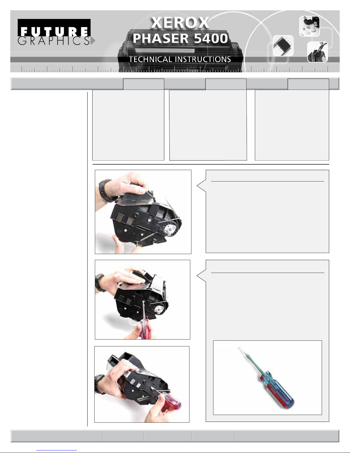
Step 1
Hold the cartridge with the gear side facing you.
Use a spring hook to remove the tension spring.
(See Photo 1)
Photo 1
Step 2
Using the HP2600PINREMTOOL to remove the
cartridge pin. Push the HP2600PINREMTOOL in
the center of the pin and turn clockwise until the
tool bores a hole and tightens onto the pin.
When tightened on the pin, you will be able to
turn the pin a ¼ turn counter clockwise. Lift the
pin straight out of the hole.
NOTE: The pin damages easily. Do not use
excessive pressure boring the hole or pulling on
the pin. (See Photo 2, 3, 4)
Photo 2
Photo 3
PHASER5400TECH
REV. 12/27/06
US 1 800 394.9900
Int’l +1 818 837.8100
FAX 1 800 394.9910
Int’l +1 818 838.7047
KANSAS CITY, USA
US 1 913 871.1700
FAX 1 913 888.0626
ATLANTA, USA
US 1 877 676.4223
Int’l +1 678 919.1189
FAX 1 877 337.7976
Int’l +1 770 516.7794
MIAMI, USA
US 1 800 595.4297
Int’l +1 305 594.3396
FAX 1 800 522.8640
Int’l +1 305 594.3309
TORONTO, CAN
CAN 1 877 848.0818
Int’l +1 905 712.9501
FAX 1 877 772.6773
Int’l +1 905 712.9502
NEW YORK, USA
US 1 800 431.7884
Int’l +1 631 588.7300
FAX 1 800 431.8812
Int’l +1 631 588.7333
SYDNEY, AUS
AUS 1 800 003.100
Int’l +62 02 9648.2630
FAX 1800 004.302
Int’l +62 02 9548.2635
BUENOS AIRES, ARG
ARG 0810 444.2656
Int’l +011 4583.5900
FAX +011 4584.3100
MONTEVIDEO, URY
URY 02 902.2001
Int’l +5982 902.2001
FAX +5982 900.0858
JOHANNESBURG, S.A.
S.A. +27 11 974.6155
FAX +27 11 974.3593
MELBOURNE, AUS
AUS 1 800 003. 100
Int’l +62 03 9561.8102
FAX 1 800 004.302
Int’l +62 03 9561-7751
CORPORATE
LOS ANGELES, USA
SÃO PAULO, BRAZIL
Int’l +55 11 5524.8000
RAANANA, ISRAEL
ISR 09 760.12.39
Int’l +972 9760.12.39
ISR 052.38.555.82
Int’l +972 5238.555.82
Photo 4
Page 2

Step 6
Remove PCR roller from saddle blocks. Set
PCR roller aside. (See Photo 9)
Step 5
Remove the drum and set aside in a light protected area.
Photo 5
Step 7
Remove the screws to the wiper blade and lift
out wiper blade. Remove waste toner using a
vacuum or dry, compressed air.
(See Photo 10)
Photo 7
Photo 8
Step 8
Clean wiper blade with a soft dry cloth or dry,
compressed air.
Apply padding powder to the blade edge and
reinstall. (See Photo 11&12)
Step 9
Clean PCR saddle blocks with cotton swab
and Anhydrous Isopropyl Alcohol. Clean PCR
using a dry, soft, lint-free cloth.
NOTE: If needed, de-ionized water can be
used to clean the PCR.
(See Photo 13&14)
Photo 9
Photo 10
2 PHASER 5400 Technical Instructions
Photo 6
Photo 11
Step 3
Rotate the cartridge to the fill plug
side. Repeat Step 2 to remove the
cartridge pin. Separate the cartridge
sections and put aside the toner
unit. (See Photo 5&6)
Step 4
Remove the screws holding the
metal drum axial and remove drum
axial. Remove screws holding white
plastic drum with contact and
remove white drum axial. (See
Photo 7&8)
Photo 12
Photo 13
Photo 14
Page 3

Photo 16
Photo 17
Photo 18
PHASER 5400 Technical Instructions 3
Step 10
Apply conductive grease to the black PCR
saddle block. Install PCR into saddle blocks.
(See Photo 15&16)
Photo 15
Step 11
Clean drum using soft dry cloth.
Apply padding powder to the drum.
(See Photo 17&18)
Photo 19
Step 12
Install the drum and drum axils. Install screws
for the drum axils. Rotate drum to ensure
smooth operation. Remove excess padding
powder using a soft dry cloth from the drum
and PCR area.
(See Photo 19&20)
Step 13
Set aside the waste unit. Protect the drum
from light exposure.
Photo 20
Photo 21
Photo 23
Photo 22
Step 14
Starting on the toner unit, remove
the gear side end cap.
(See Photo 21)
Step 15
Lift up on the mag roller release
handle. Remove the mag roller from
the cartridge. Use a vacuum or dry
compressed air to remove toner.
(See Photo 22&23)
Page 4

Step 19
Remove the fill plug and clean remaining
toner using a vacuum or dry compressed air.
(See Photo 28)
Step 18
Remove the doctor blade. Use a vacuum or
dry compressed air to remove toner. Clean
the doctor blade using a dry, soft, lint-free
cloth and set aside for later.
(See Photo 26&27)
Step 20
Reinstall the doctor blade.
(See Photo 29)
Photo 26
Step 21
Reinstall gear spacer, mag roller drive gear,
latch spacer, and mag roller latch onto mag
roller. Install mag roller into toner unit. Lock
mag roller into place by pushing the latch
down until it clicks into place.
(See Photo 30&31)
Photo 27
Photo 28
4 PHASER 5400 Technical Instructions
Photo 29
Photo 30
Photo 31
Photo 25
Photo 24
Step 16
Remove from the mag roller: the
latch, latch spacer, gear spacer,
and mag roller drive gear. Clean
with a soft dry cloth and set aside
for later.
(See Photo 24)
Step 17
Clean the mag roller using a soft,
lint-free cloth and MAGCLEANER.
Set aside for later.
(See Photo 25)
Page 5

Photo 34
Photo 35
PHASER 5400 Technical Instructions 5
Photo 33
Photo 37
Photo 36
Photo 38
Step 25
Hold the cartridge with the gear
side facing you. Use a spring hook
to install the tension spring into the
mounting holes. (See Photo 38)
Photo 32
Step 22
Fill toner hopper with toner. Install fill plug
when toner fill is complete.
(See Photo 32&33)
In October of 2001, Xerox released the Phaser 5400 laser
printer. The Xerox Phaser is a 40ppm printer with a maximum
monthly duty cycle of 200,000 pages.
One cartridge capacity is available, 20K pages.
XEROX PHASER 5400
Step 23
Step 23: Remove the cartridge chip located
on the toner unit fill plug. Install new chip.
(See Photo 34&35)
Step 24
Join the toner and waste unit together. Ensure
that the toner unit spring is in the alignment
hole of the waste unit. Install the cartridge
pins into the cartridge. Align the pin tabs to
the slots in the cartridge. Use a small blade
screw driver to turn the pin to the lock position (¼ turn). (See Photo 36&37)
 Loading...