

Page 1
Service
Phaser® 3150
laser printer
Manual
Page 2

Phaser 3150 Laser Printer
Service Manual
Warning
The following servicing instructions are for use by qualified service personnel only. To avoid personal injury, do
not perform any servicing other than that contained in the operating instructions, unless you are qualified to do
so.
First Printing: July 2004
721P58540
Page 3

Copyright © 2004 Xerox Corporation. All Rights Reserved. Unpublished rights reserved under the copyright laws of the United States. Contents of
this publication may not be reproduced in any form without permission of Xerox Corporation.
Copyright protection claimed includes all forms of matters of copyrightable materials and information now allowed by statutory or judicial law or
hereinafter granted, including without limitation, material generated from the software programs which are displayed on the screen such as styles,
templates, icons, screen displays, looks, etc.
®
XEROX
Walk-Up
Adobe
Birch
, The Document Company®, the stylized X®, CentreWare®, infoSMART®, Made For Each Other®, Phaser®, PhaserSMART®, and
™
are trademarks of Xerox Corporation in the United States and/or other countries.
®
Reader®, Illustrator®, PageMaker®, Photoshop®, PostScript®, ATM®, Adobe Brilliant® Screens, Adobe Garamond®, Adobe Jenson™,
®
, Carta®, IntelliSelect®, Mythos®, Quake®, and Tekton® are trademarks of Adobe Systems Incorporated in the United States and/or other
countries.
®
, AppleTalk®, LaserWriter®, LocalTalk®, Macintosh®, Mac OS®, TrueType®, Apple Chancery®, Chicago®, Geneva®, Monaco®, New
Apple
®
, and QuickDraw® are trademarks of Apple Computer, Inc. in the United States and/or other countries.
York
®
and HP-GL® are trademarks of Hewlett-Packard Corporation in the United States and/or other countries.
PCL
®
is a trademark of International Business Machines Corporation in the United States and/or other countries.
IBM
®
Windows
Novell
, Windows NT®, and Wingdings® are trademarks of Microsoft Corporation in the United States and/or other countries.
®
, NetWare®, NDPS®, NDS®, Novell Directory Services® , IPX™ , and Novell Distributed Print Services™are trademarks of Novell,
Incorporated in the United States and/or other countries.
®
and Sun Microsystems® are trademarks of Sun Microsystems, Incorporated in the United States and/or other countries.
Sun
®
is a trademark in the United States and other countries, licensed exclusively through X/Open Company Limited.
UNIX
NERGY STAR
As an E
E
NERGY STAR name and logo are registered U.S. marks.
®
partner, Xerox Corporation has determined that this product meets the ENERGY STAR guidelines for energy efficiency. The
MD/TA
Page 4

1 Precautions
1.1 Safety Warnings . . . . . . . . . . . . . . . . . . . . . . . . . . . . . . . . . . . . . . . . . . . . . . . . . . . . 1-1
1.2 Safety Cautions. . . . . . . . . . . . . . . . . . . . . . . . . . . . . . . . . . . . . . . . . . . . . . . . . . . . . 1-2
1.2.1 Toxic Material . . . . . . . . . . . . . . . . . . . . . . . . . . . . . . . . . . . . . . . . . . . . . . . 1-2
1.2.2 Electric Shock and Fire Safety Precautions . . . . . . . . . . . . . . . . . . . . . . . . . 1-2
1.2.3 Handling Precautions . . . . . . . . . . . . . . . . . . . . . . . . . . . . . . . . . . . . . . . . . . 1-3
1.2.4 Assembly and Disassembly Precautions . . . . . . . . . . . . . . . . . . . . . . . . . . . 1-3
1.2.5 Bodily Injury Warnings . . . . . . . . . . . . . . . . . . . . . . . . . . . . . . . . . . . . . . . . 1-4
1.3 ESD Precautions. . . . . . . . . . . . . . . . . . . . . . . . . . . . . . . . . . . . . . . . . . . . . . . . . . . . 1-5
2 Reference Information
2.1 Tools for Troubleshooting the Printer . . . . . . . . . . . . . . . . . . . . . . . . . . . . . . . . . . . 2-1
2.2 Acronyms and Abbreviations . . . . . . . . . . . . . . . . . . . . . . . . . . . . . . . . . . . . . . . . . . 2-2
2.3 Selecting a Location for the Printer . . . . . . . . . . . . . . . . . . . . . . . . . . . . . . . . . . . . . 2-4
3 Specifications
3.1 General Specifications . . . . . . . . . . . . . . . . . . . . . . . . . . . . . . . . . . . . . . . . . . . . . . . 3-1
3.2 Controller/Software Specifications. . . . . . . . . . . . . . . . . . . . . . . . . . . . . . . . . . . . . . 3-2
3.3 Electrical Specifications . . . . . . . . . . . . . . . . . . . . . . . . . . . . . . . . . . . . . . . . . . . . . . 3-2
3.4 Environmental Range . . . . . . . . . . . . . . . . . . . . . . . . . . . . . . . . . . . . . . . . . . . . . . . . 3-3
3.6 Media Specifications . . . . . . . . . . . . . . . . . . . . . . . . . . . . . . . . . . . . . . . . . . . . . . . . 3-3
3.6.1 Approved Paper Size and Weights. . . . . . . . . . . . . . . . . . . . . . . . . . . . . . . . 3-3
3.6.2 Print Margins and Skew . . . . . . . . . . . . . . . . . . . . . . . . . . . . . . . . . . . . . . . . 3-3
4 Product Summary
4.1 Printer Components . . . . . . . . . . . . . . . . . . . . . . . . . . . . . . . . . . . . . . . . . . . . . . . . . 4-1
4.1.1 Front View . . . . . . . . . . . . . . . . . . . . . . . . . . . . . . . . . . . . . . . . . . . . . . . . . . 4-1
4.1.2 Rear View. . . . . . . . . . . . . . . . . . . . . . . . . . . . . . . . . . . . . . . . . . . . . . . . . . . 4-2
4.1.3 Control Panel . . . . . . . . . . . . . . . . . . . . . . . . . . . . . . . . . . . . . . . . . . . . . . . . 4-2
4.2 Printer Theory of Operation . . . . . . . . . . . . . . . . . . . . . . . . . . . . . . . . . . . . . . . . . . . 4-4
4.2.1 System Summary . . . . . . . . . . . . . . . . . . . . . . . . . . . . . . . . . . . . . . . . . . . . . 4-4
4.2.2 System Layout . . . . . . . . . . . . . . . . . . . . . . . . . . . . . . . . . . . . . . . . . . . . . . . 4-5
4.2.3 Paper Feed . . . . . . . . . . . . . . . . . . . . . . . . . . . . . . . . . . . . . . . . . . . . . . . . . . 4-5
4.2.4 Transfer Assembly . . . . . . . . . . . . . . . . . . . . . . . . . . . . . . . . . . . . . . . . . . . . 4-6
4.2.5 Drive Assembly . . . . . . . . . . . . . . . . . . . . . . . . . . . . . . . . . . . . . . . . . . . . . . 4-6
4.2.6 Fuser Assembly . . . . . . . . . . . . . . . . . . . . . . . . . . . . . . . . . . . . . . . . . . . . . . 4-6
4.2.7 Laser Scanner Unit (LSU) . . . . . . . . . . . . . . . . . . . . . . . . . . . . . . . . . . . . . . 4-7
4.2.8 Toner Cartridge. . . . . . . . . . . . . . . . . . . . . . . . . . . . . . . . . . . . . . . . . . . . . . . 4-7
4.3 Main Controller Board (PBA) . . . . . . . . . . . . . . . . . . . . . . . . . . . . . . . . . . . . . . . . . 4-8
4.3.1 ASIC (SPGPm). . . . . . . . . . . . . . . . . . . . . . . . . . . . . . . . . . . . . . . . . . . . . . . 4-9
4.3.2 Memory . . . . . . . . . . . . . . . . . . . . . . . . . . . . . . . . . . . . . . . . . . . . . . . . . . . . 4-9
4.3.3 Flash Memory. . . . . . . . . . . . . . . . . . . . . . . . . . . . . . . . . . . . . . . . . . . . . . . . 4-9
4.3.4 SDRAM . . . . . . . . . . . . . . . . . . . . . . . . . . . . . . . . . . . . . . . . . . . . . . . . . . . 4-10
4.3.5 Sensor Input Circuit . . . . . . . . . . . . . . . . . . . . . . . . . . . . . . . . . . . . . . . . . . 4-10
4.4 Switching Mode Power Supply (SMPS) and High Voltage Power Supply (HVPS)4-12
4.4.1 High Voltage Power Supply. . . . . . . . . . . . . . . . . . . . . . . . . . . . . . . . . . . . 4-13
4.4.2 Switching Mode Power Supply . . . . . . . . . . . . . . . . . . . . . . . . . . . . . . . . . 4-14
Page 5

4.5 Engine F/W. . . . . . . . . . . . . . . . . . . . . . . . . . . . . . . . . . . . . . . . . . . . . . . . . . . . . . . 4-15
4.5.1 Feeding . . . . . . . . . . . . . . . . . . . . . . . . . . . . . . . . . . . . . . . . . . . . . . . . . . . . 4-15
5 Disassembly
5.1 Precautions for Disassembly/Reassembly . . . . . . . . . . . . . . . . . . . . . . . . . . . . . . . . 5-1
5.1.1 Precautions When Removing Circuit Boards. . . . . . . . . . . . . . . . . . . . . . . . 5-1
5.2 Front Cover. . . . . . . . . . . . . . . . . . . . . . . . . . . . . . . . . . . . . . . . . . . . . . . . . . . . . . . . 5-3
5.3 Tray 1/MPT Assembly . . . . . . . . . . . . . . . . . . . . . . . . . . . . . . . . . . . . . . . . . . . . . . . 5-4
5.4 Rear Cover . . . . . . . . . . . . . . . . . . . . . . . . . . . . . . . . . . . . . . . . . . . . . . . . . . . . . . . . 5-5
5.5 Top Cover. . . . . . . . . . . . . . . . . . . . . . . . . . . . . . . . . . . . . . . . . . . . . . . . . . . . . . . . . 5-6
5.6 Middle Cover . . . . . . . . . . . . . . . . . . . . . . . . . . . . . . . . . . . . . . . . . . . . . . . . . . . . . . 5-7
5.7 Side Cover (Left and Right) . . . . . . . . . . . . . . . . . . . . . . . . . . . . . . . . . . . . . . . . . . . 5-8
5.8 Exit Roller. . . . . . . . . . . . . . . . . . . . . . . . . . . . . . . . . . . . . . . . . . . . . . . . . . . . . . . . . 5-9
5.9 Engine Shield Assembly and Exit Board . . . . . . . . . . . . . . . . . . . . . . . . . . . . . . . . 5-10
5.10.1 SMPS. . . . . . . . . . . . . . . . . . . . . . . . . . . . . . . . . . . . . . . . . . . . . . . . . . . . . . . . . 5-12
5.10.2 Main Board . . . . . . . . . . . . . . . . . . . . . . . . . . . . . . . . . . . . . . . . . . . . . . . . . . . . 5-13
5.10.3 Removing the Network Card or Optional Memory Modules . . . . . . . . . . . . . . 5-14
5.11 Fuser Assembly . . . . . . . . . . . . . . . . . . . . . . . . . . . . . . . . . . . . . . . . . . . . . . . . . . 5-15
5.12 Fan . . . . . . . . . . . . . . . . . . . . . . . . . . . . . . . . . . . . . . . . . . . . . . . . . . . . . . . . . . . . 5-18
5.13 Laser Scanner Unit (LSU) . . . . . . . . . . . . . . . . . . . . . . . . . . . . . . . . . . . . . . . . . . 5-19
5.14 Drive Assembly . . . . . . . . . . . . . . . . . . . . . . . . . . . . . . . . . . . . . . . . . . . . . . . . . . 5-20
5.15 Transfer Assembly . . . . . . . . . . . . . . . . . . . . . . . . . . . . . . . . . . . . . . . . . . . . . . . . 5-21
5.16.1 Tray 1/MPT Assembly . . . . . . . . . . . . . . . . . . . . . . . . . . . . . . . . . . . . . . . . . . . 5-22
5.16.2 Feed Roller. . . . . . . . . . . . . . . . . . . . . . . . . . . . . . . . . . . . . . . . . . . . . . . . . . . . . 5-23
5.17 Pick-Up Assembly, Solenoids, and Pick Roller. . . . . . . . . . . . . . . . . . . . . . . . . . 5-25
6 Alignment and Adjustments
6.1 How to Use the Diagnostic Control Unit (DCU) . . . . . . . . . . . . . . . . . . . . . . . . . . . 6-1
6.1.1 DCU Setup . . . . . . . . . . . . . . . . . . . . . . . . . . . . . . . . . . . . . . . . . . . . . . . . . . 6-1
6.1.2 Status Monitoring Code . . . . . . . . . . . . . . . . . . . . . . . . . . . . . . . . . . . . . . . . 6-2
Normal Code Table . . . . . . . . . . . . . . . . . . . . . . . . . . . . . . . . . . . . . . . . . . . 6-2
Error Codes . . . . . . . . . . . . . . . . . . . . . . . . . . . . . . . . . . . . . . . . . . . . . . . . . 6-2
6.1.3 Self Diagnostic Mode . . . . . . . . . . . . . . . . . . . . . . . . . . . . . . . . . . . . . . . . . . 6-3
6.2 Paper Path. . . . . . . . . . . . . . . . . . . . . . . . . . . . . . . . . . . . . . . . . . . . . . . . . . . . . . . . . 6-6
6.3 Clearing Paper Jams . . . . . . . . . . . . . . . . . . . . . . . . . . . . . . . . . . . . . . . . . . . . . . . . . 6-7
6.3.1 Jam2: Paper in the Exit Area . . . . . . . . . . . . . . . . . . . . . . . . . . . . . . . . . . . . 6-7
6.3.2 Jam0: Paper in the Feed Area. . . . . . . . . . . . . . . . . . . . . . . . . . . . . . . . . . . . 6-8
6.3.3 Jam1: Paper Around the Toner Cartridge. . . . . . . . . . . . . . . . . . . . . . . . . . . 6-8
6.3.4 Tips for Avoiding Paper Jams . . . . . . . . . . . . . . . . . . . . . . . . . . . . . . . . . . . 6-9
6.4 Sample Patterns. . . . . . . . . . . . . . . . . . . . . . . . . . . . . . . . . . . . . . . . . . . . . . . . . . . . . 6-9
6.4.1 Printing a Demo or Configuration Page . . . . . . . . . . . . . . . . . . . . . . . . . . . . 6-9
6.4.2 Printing a Cleaning Sheet . . . . . . . . . . . . . . . . . . . . . . . . . . . . . . . . . . . . . . . 6-9
6.5 Consumables and Replacement Parts. . . . . . . . . . . . . . . . . . . . . . . . . . . . . . . . . . . 6-10
6.6 The LED Display Status for Each Error. . . . . . . . . . . . . . . . . . . . . . . . . . . . . . . . . 6-10
6.7 Periodic Defective Image (Repeating Defects) . . . . . . . . . . . . . . . . . . . . . . . . . . . 6-11
Page 6

7 Troubleshooting
7.1 Print Quality Problems . . . . . . . . . . . . . . . . . . . . . . . . . . . . . . . . . . . . . . . . . . . . . . . 7-1
7.1.1 Vertical Black Line and Band . . . . . . . . . . . . . . . . . . . . . . . . . . . . . . . . . . . 7-1
7.1.2 Vertical White Lines. . . . . . . . . . . . . . . . . . . . . . . . . . . . . . . . . . . . . . . . . . . 7-1
7.1.3 Horizontal Black Band . . . . . . . . . . . . . . . . . . . . . . . . . . . . . . . . . . . . . . . . . 7-2
7.1.4 Black/White Spot . . . . . . . . . . . . . . . . . . . . . . . . . . . . . . . . . . . . . . . . . . . . . 7-2
7.1.5 Light Image. . . . . . . . . . . . . . . . . . . . . . . . . . . . . . . . . . . . . . . . . . . . . . . . . . 7-3
7.1.6 Dark Image or Completely Black Print . . . . . . . . . . . . . . . . . . . . . . . . . . . . 7-3
7.1.7 Uneven Density . . . . . . . . . . . . . . . . . . . . . . . . . . . . . . . . . . . . . . . . . . . . . . 7-4
7.1.8 Background Contamination . . . . . . . . . . . . . . . . . . . . . . . . . . . . . . . . . . . . . 7-4
7.1.9 Ghosting 1. . . . . . . . . . . . . . . . . . . . . . . . . . . . . . . . . . . . . . . . . . . . . . . . . . . 7-5
7.1.10 Ghosting 2. . . . . . . . . . . . . . . . . . . . . . . . . . . . . . . . . . . . . . . . . . . . . . . . . . 7-5
7.1.11 Ghosting 3. . . . . . . . . . . . . . . . . . . . . . . . . . . . . . . . . . . . . . . . . . . . . . . . . . 7-6
7.1.12 Ghosting 4. . . . . . . . . . . . . . . . . . . . . . . . . . . . . . . . . . . . . . . . . . . . . . . . . . 7-6
7.1.13 Stains on the Front of the Page. . . . . . . . . . . . . . . . . . . . . . . . . . . . . . . . . . 7-6
7.1.14 Stains on the Back of the Page . . . . . . . . . . . . . . . . . . . . . . . . . . . . . . . . . . 7-7
7.1.15 Blank Page is Printed 1. . . . . . . . . . . . . . . . . . . . . . . . . . . . . . . . . . . . . . . . 7-7
7.1.16 Blank Page is Printed 2. . . . . . . . . . . . . . . . . . . . . . . . . . . . . . . . . . . . . . . . 7-7
7.2 Paper Feed Problems . . . . . . . . . . . . . . . . . . . . . . . . . . . . . . . . . . . . . . . . . . . . . . . . 7-8
7.2.1 Wrong Print Position . . . . . . . . . . . . . . . . . . . . . . . . . . . . . . . . . . . . . . . . . . 7-8
7.2.2 Jam 0. . . . . . . . . . . . . . . . . . . . . . . . . . . . . . . . . . . . . . . . . . . . . . . . . . . . . . . 7-8
7.2.3 Jam 1. . . . . . . . . . . . . . . . . . . . . . . . . . . . . . . . . . . . . . . . . . . . . . . . . . . . . . . 7-9
7.2.4 Jam 2. . . . . . . . . . . . . . . . . . . . . . . . . . . . . . . . . . . . . . . . . . . . . . . . . . . . . . . 7-9
7.2.5 Multiple Pick . . . . . . . . . . . . . . . . . . . . . . . . . . . . . . . . . . . . . . . . . . . . . . . 7-10
7.2.6 Paper Rolled in the Fuser . . . . . . . . . . . . . . . . . . . . . . . . . . . . . . . . . . . . . . 7-10
7.2.7 Paper Rolled in the OPC Drum . . . . . . . . . . . . . . . . . . . . . . . . . . . . . . . . . 7-10
7.3 Printer Faults . . . . . . . . . . . . . . . . . . . . . . . . . . . . . . . . . . . . . . . . . . . . . . . . . . . . . 7-11
7.3.1 All LEDs Blinking (Fuser Error) . . . . . . . . . . . . . . . . . . . . . . . . . . . . . . . . 7-11
7.3.2 All LEDs Blinking (Scan Error). . . . . . . . . . . . . . . . . . . . . . . . . . . . . . . . . 7-11
7.3.3 Fuser Gear Melted Due to Overheating, Causing a Paper Jam . . . . . . . . . 7-11
7.3.4 Paper Empty Error . . . . . . . . . . . . . . . . . . . . . . . . . . . . . . . . . . . . . . . . . . . 7-12
7.3.5 Paper Empty Error Without Indication. . . . . . . . . . . . . . . . . . . . . . . . . . . . 7-12
7.3.6 Cover Open. . . . . . . . . . . . . . . . . . . . . . . . . . . . . . . . . . . . . . . . . . . . . . . . . 7-12
7.3.7 No Error Lamp When the Cover is Open. . . . . . . . . . . . . . . . . . . . . . . . . . 7-13
7.3.8 Defective Motor Operation. . . . . . . . . . . . . . . . . . . . . . . . . . . . . . . . . . . . . 7-13
7.3.9 No Power . . . . . . . . . . . . . . . . . . . . . . . . . . . . . . . . . . . . . . . . . . . . . . . . . . 7-13
7.3.10 Printed Vertical Lines Become Curved . . . . . . . . . . . . . . . . . . . . . . . . . . 7-14
7.4 Toner Cartridge Servicing . . . . . . . . . . . . . . . . . . . . . . . . . . . . . . . . . . . . . . . . . . . 7-15
7.4.1 Precautions for Toner Cartridges . . . . . . . . . . . . . . . . . . . . . . . . . . . . . . . . 7-15
7.4.2 Toner Cartridge Life. . . . . . . . . . . . . . . . . . . . . . . . . . . . . . . . . . . . . . . . . . 7-15
7.4.3 Redistributing Toner. . . . . . . . . . . . . . . . . . . . . . . . . . . . . . . . . . . . . . . . . . 7-15
7.5 Software Problems . . . . . . . . . . . . . . . . . . . . . . . . . . . . . . . . . . . . . . . . . . . . . . . . . 7-16
7.5.1 The Printer is Not Responding to the Print Command. . . . . . . . . . . . . . . . 7-16
7.5.2 The Printer is Not Responding to a Print Command or
Strange Fonts are Printing . . . . . . . . . . . . . . . . . . . . . . . . . . . . . . . . . . . . . 7-16
7.5.3 SPOOL Error . . . . . . . . . . . . . . . . . . . . . . . . . . . . . . . . . . . . . . . . . . . . . . . 7-17
Page 7

8 Parts List
8.1 Main Assembly. . . . . . . . . . . . . . . . . . . . . . . . . . . . . . . . . . . . . . . . . . . . . . . . . . . . . 8-2
Main Assembly Parts List 8.1 . . . . . . . . . . . . . . . . . . . . . . . . . . . . . . . . . . . . . . . . 8-3
8.2 Frame Unit Assemly. . . . . . . . . . . . . . . . . . . . . . . . . . . . . . . . . . . . . . . . . . . . . . . . . 8-5
Frame Unit Assembly Parts List 8.2 . . . . . . . . . . . . . . . . . . . . . . . . . . . . . . . . . . . 8-6
8.3 MP Assembly . . . . . . . . . . . . . . . . . . . . . . . . . . . . . . . . . . . . . . . . . . . . . . . . . . . . . . 8-8
MP Assembly Parts List 8.3 . . . . . . . . . . . . . . . . . . . . . . . . . . . . . . . . . . . . . . . . . 8-9
8.4 Fuser Unit Assembly . . . . . . . . . . . . . . . . . . . . . . . . . . . . . . . . . . . . . . . . . . . . . . . 8-10
Fuser Assembly Parts List 8.4 . . . . . . . . . . . . . . . . . . . . . . . . . . . . . . . . . . . . . . 8-11
8.5 Main Drive Unit Assembly. . . . . . . . . . . . . . . . . . . . . . . . . . . . . . . . . . . . . . . . . . . 8-12
Main Drive Unit Assembly Parts List 8.5 . . . . . . . . . . . . . . . . . . . . . . . . . . . . . . 8-12
8.6 Tray 2 (Cassette) Unit Assembly . . . . . . . . . . . . . . . . . . . . . . . . . . . . . . . . . . . . . . 8-13
Tray 2 (Cassette) Unit Assembly Parts List 8.6. . . . . . . . . . . . . . . . . . . . . . . . . . 8-14
8.7 Tray 3 (SCF - Optional Cassette) Unit Assembly . . . . . . . . . . . . . . . . . . . . . . . . . 8-15
Tray 3 (SCF - Optional Cassette) Assembly Parts List 8.7. . . . . . . . . . . . . . . . . 8-16
Xerox Options and Accessories . . . . . . . . . . . . . . . . . . . . . . . . . . . . . . . . . . . . . . . . . . 8-17
9 Block Diagram
10 Connection Diagram
Page 8
Precautions
Precautions
1
In order to prevent accidents and to prevent damage to the printer, please read the precautions listed below carefully
before servicing the printer.
1.1 Safety Warnings
1. Only to be serviced by appropriately qualified service engineers.
High voltages and lasers inside this product are dangerous. This printer should only be serviced by a suitably
trained and qualified service engineer.
2. Use only Xerox replacement parts.
There are no user serviceable parts inside the printer. Do not make any unauthorized changes or additions to the
printer, these could cause the printer to malfunction and create electric shock or fire hazards.
3. Laser Safety Statement
The Printer is certified in the U.S. to conform to the requirements of DHHS 21 CFR, chapter 1 Subchapter J for
Class 1 laser products, and elsewhere, it is certified as a Class 1 laser product conforming to the requirements of
IEC 825. Class 1 laser products are not considered to be hazardous. The laser system and printer are designed so
there is never access to laser radiation above a Class 1 level during normal operation, user maintenance, or
prescribed service condition.
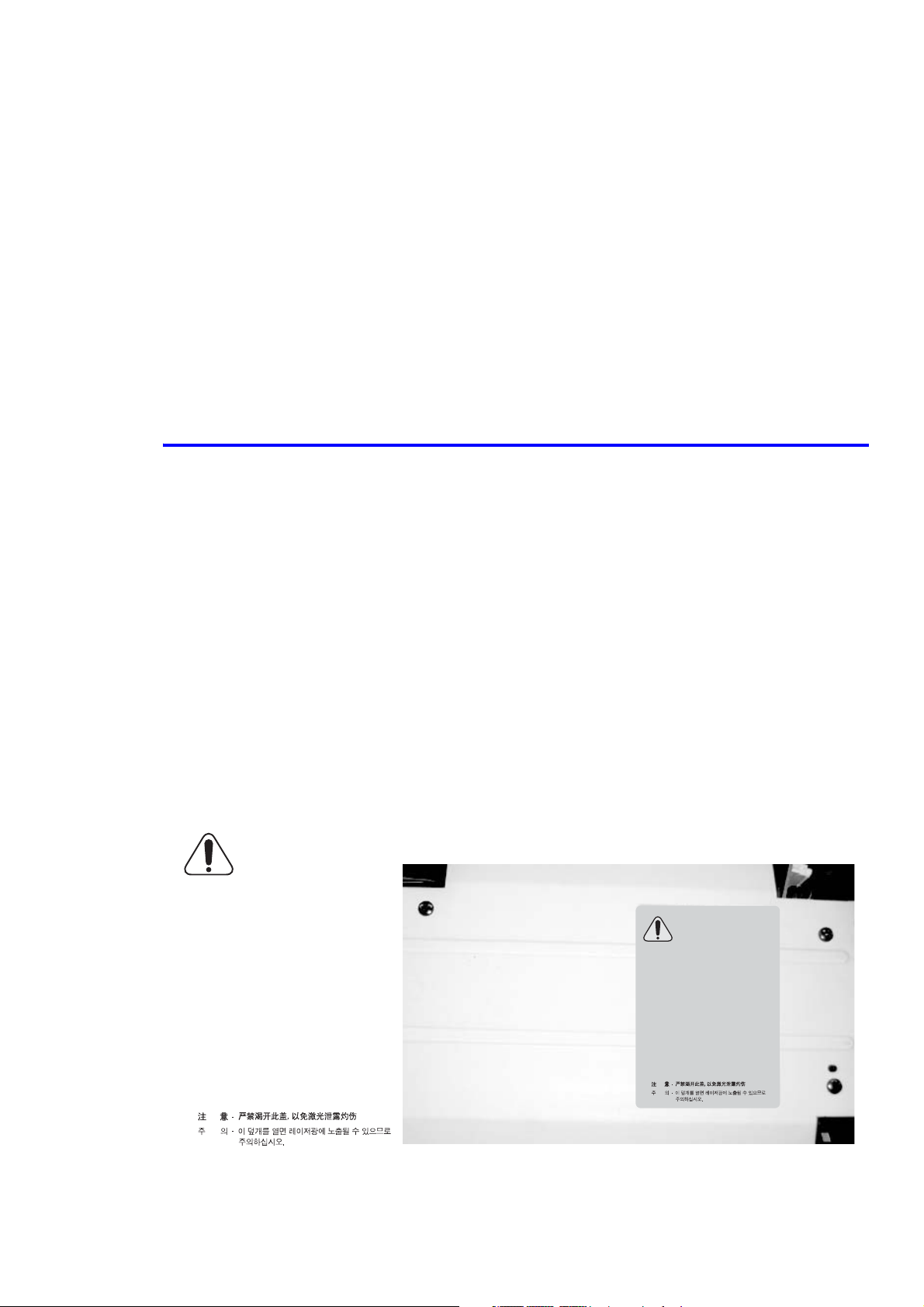
Warning
Never operate or service the printer with the protective cover removed from Laser assembly. The reflected
beam, although invisible, can damage your eyes. When using this product, these basic safety precautions
should always be followed to reduce the risk of fire, electrical shock, and bodily injury.
CAUTION - INVISIBLE LASER RADIATION
WHEN THIS COVER OPEN.
DO NOT OPEN THIS COVER.
VORSICHT - UNSICHTBARE LASERSTRAHLUNG,
WENN ABDECKUNG GEÖFFNET.
ATTENTION - RAYONNEMENT LASER INVISIBLE EN CAS
ATTENZIONE - RADIAZIONE LASER INVISIBILE IN CASO DI
PRECAUCION - RADIACION LASER IVISIBLE CUANDO SE ABRE.
D’OUVERTURE. EXPOSITION DANGEREUSE
AU FAISCEAU.
APERTURA. EVITARE L’ESPOSIZIONE AL
FASCIO.
EVITAR EXPONERSE AL RAYO.
ADVARSEL. - USYNLIG LASERSTRÅLNING VED ÅBNING, NÅR
SIKKERHEDSBRYDERE ER UDE AF FUNKTION.
UNDGÅ UDSAETTELSE FOR STRÅLNING.
ADVARSEL. - USYNLIG LASERSTRÅLNING NÅR DEKSEL
ÅPNES. STIRR IKKE INN I STRÅLEN.
UNNGÅ EKSPONERING FOR STRÅLEN.
VARNING - OSYNLIG LASERSTRÅLNING NÄR DENNA DEL
ÄR ÖPPNAD OCH SPÄRREN ÄR URKOPPLAD.
BETRAKTA EJ STRÅLEN. STRÅLEN ÄR FARLIG.
VARO! - AVATTAESSA JA SUOJALUKITUS OHITETTAESSA
OLET ALTTIINA NÄKYMÄTTÖMÄLLE LASERSÄTEILYLLE ÄLÄ KATSO SÄTEESEEN.
NICHT DEM STRAHL AUSSETZEN.
CAUTION - INVISIBLE LASER RADIATION
WHEN THIS COVER OPEN.
DO NOT OPEN THIS COVER.
VORSICHT - UNSICHTBARE LASERSTRAHLUNG,
WENN ABDECKUNG GEÖFFNET.
ATTENTION - RAYONNEMENT LASER INVISIBLE EN CAS
ATTENZIONE - RADIAZIONE LASER INVISIBILE IN CASO DI
PRECAUCION - RADIACION LASER IVISIBLE CUANDO SE ABRE.
ADVARSEL. - USYNLIG LASERSTRÅLNING VED ÅBNING, NÅR
ADVARSEL. - USYNLIG LASERSTRÅLNING NÅR DEKSEL
VARNING - OSYNLIG LASERSTRÅLNING NÄR DENNA DEL
NICHT DEM STRAHL AUSSETZEN.
D’OUVERTURE. EXPOSITION DANGEREUSE
AU FAISCEAU.
APERTURA. EVITARE L’ESPOSIZIONE AL
FASCIO.
EVITAR EXPONERSE AL RAYO.
SIKKERHEDSBRYDERE ER UDE AF FUNKTION.
UNDGÅ UDSAETTELSE FOR STRÅLNING.
ÅPNES. STIRR IKKE INN I STRÅLEN.
UNNGÅ EKSPONERING FOR STRÅLEN.
ÄR ÖPPNAD OCH SPÄRREN ÄR URKOPPLAD.
BETRAKTA EJ STRÅLEN. STRÅLEN ÄR FARLIG.
VARO! - AVATTAESSA JA SUOJALUKITUS OHITETTAESSA
OLET ALTTIINA NÄKYMÄTTÖMÄLLE LASERSÄTEILYLLE ÄLÄ KATSO SÄTEESEEN.
Service Manual 1-1
Page 9

Precautions
1.2 Safety Cautions
1.2.1 Toxic Material
This product contains toxic materials that could cause illness if ingested.
1. Please keep toner cartridges away from children. The toner powder contained in the toner cartridge may be
harmful and if swallowed you should contact a doctor immediately.
1.2.2 Electric Shock and Fire Safety Precautions
Failure to follow the following instructions could cause electric shock or potentially cause a fire:
1. Use only the correct voltage, failure to do so could damage the printer and potentially cause a fire or electric
shock.
2. Use only the power cable supplied with the printer. Use of an incorrectly specified cable could cause the cable to
overheat and potentially cause a fire hazard.
3. Do not overload the power socket, this could lead to overheating of the cables inside the wall and could lead to a
fire hazard.
4. Do not allow water or other liquids to spill into the printer, this can cause electric shock. Do not allow paper
clips, pins, or other foreign objects to fall into the printer as these could cause a short circuit leading to electric
shock or fire hazard.
5. Never touch the plugs on either end of the power cable with wet hands, this can cause electric shock. When
servicing the printer, remove the power plug from the wall socket.
6. Use caution when inserting or removing the power connector. The power connector must be inserted completely
otherwise poor contact could cause overheating possibly leading to a fire. When removing the power connector,
grip it firmly and pull.
7. Do not allow the power cable to become twisted, bent sharply round corners or otherwise damaged. Do not place
objects on top of the power cable. If the power cable is damaged, it could overheat and cause a fire or exposed
cables could cause an electric shock. Replace a damaged power cable immediately, do not reuse or repair the
damaged cable. Some chemicals can eat through the coating on the power cable, weakening the cover, or
exposing cables causing fire and shock risks.
8. Ensure that the power sockets and plugs are not cracked or broken in any way . Any defects should be repaired or
replaced immediately. Take care not to cut or damage the power cable or plugs when moving the printer.
9. Use caution during thunder or lightening storms. Xerox recommends that this printer be disconnected from the
power source when such weather conditions are present. Do not touch the printer or the power cord if it is still
connected to the wall socket in these weather conditions.
10. Avoid damp or dusty areas, install the printer in a clean well ventilated location. Do not position the printer near
a humidifier. Damp and dust build up inside the printer can lead to overheating and cause a fire.
11. Do not position the printer in direct sunlight. This will cause the temperature inside the printer to rise leading to
the printer failing to work properly and in extreme conditions could lead to a fire.
12. Do not insert any metal objects into the printer through the ventilator fan or other parts of the casing, it could
come into contact with a high voltage conductor inside the printer and cause an electric shock.
1-2
Page 10
Precautions
L"HOT CAUTION" LABEL
L
"HOT CAUTION" LABEL
1.2.3 Handling Precautions
The following instructions are for personal safety, to avoid injury, and to avoiddamage the printer
1. Ensure the printer is installed on a level surface, capable of supporting its weight. Failure to do so could cause the
printer to tip or fall.
2. The printer contains many rollers, gears, and fans. Take great care to ensure that you do not catch your fingers,
hair, or clothing in any of these rotating devices.
3. Do not place any small metal objects, containers of water, chemicals, or other liquids close to the printer which if
spilled could get into the printer and cause damage, electric shock, or a fire hazard.
4. Do not install the printer in areas with high dust or moisture levels, beside an open window, or close to a
humidifier or heater.
5. Do not place candles or burning cigarettes on the printer.These can cause a fire.
1.2.4 Assembly and Disassembly Precautions
Always use Xerox parts. Take care to note the exact location of parts and cable routing before disassembling any part
of the printer. Ensure all parts and cables are replaced correctly.
Please carry out the following procedures before disassembly or replacing any parts:
1. Check the contents of the printer memory and make a note of any user settings. These will be erased if the
mainboard or network card is replaced.
2. Ensure that power is disconnected from the wall socket before servicing or replacing any electrical parts.
3. Disconnect printer interface cables and power cables before servicing or replacing any parts.
4. Only use approved spare parts. Ensure that part number, product name, any voltage, current, or temperature
rating are correct.
5. When removing or re-fitting any parts do not use excessive force, especially when fitting screws into plastic.
6. Take care not to drop any small parts into the printer.
Handling of the OPC Drum
The OPC Drum can be irreparably damaged if:
■ Exposed to light. Tak e care not to expose
the OPC Drum either to direct sunlight or to
fluorescent or incandescent room lighting.
Exposure for as little as 5 minutes can
damage the surface photoconductive
"HOT CAUTION" LABE
"HOT CAUTION" LABE
properties and will result in print quality
degradation. T ake e xtra care when servicing
the printer. Remove the OPC Drum and
store it in a black bag or other lightproof
container.
■ Take care when working with the covers
(especially the top cover) open as light is
admitted to the OPC area and can damage
the OPC Drum.
■ T ake care not to scratch the green surf ace of
OPC Drum Unit.
■ If the green surface of the Drum Cartridge
110V
"HOT CAUTION" LABEL
"HOT CAUTION" LABEL
is scratched or touched, the print quality
will be compromised.
220V
Service Manual 1-3
Page 11
Precautions
1.2.5 Bodily Injury Warnings
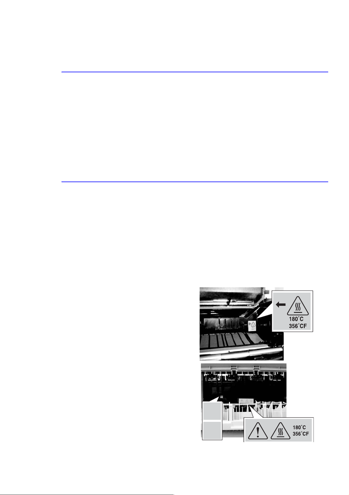
1. Use caution around high temperature parts.
The fuser unit works at a high temperature. Use caution when working on the printer. Wait for the fuser to cool
down before disassembly.
2. Use caution when around rotating parts.
When operating the printer, do not put your hands into the rotating parts (Paper feeding entrance, motor, fan,
etc.). Remove jewelry and loose clothing before servicing the printer.
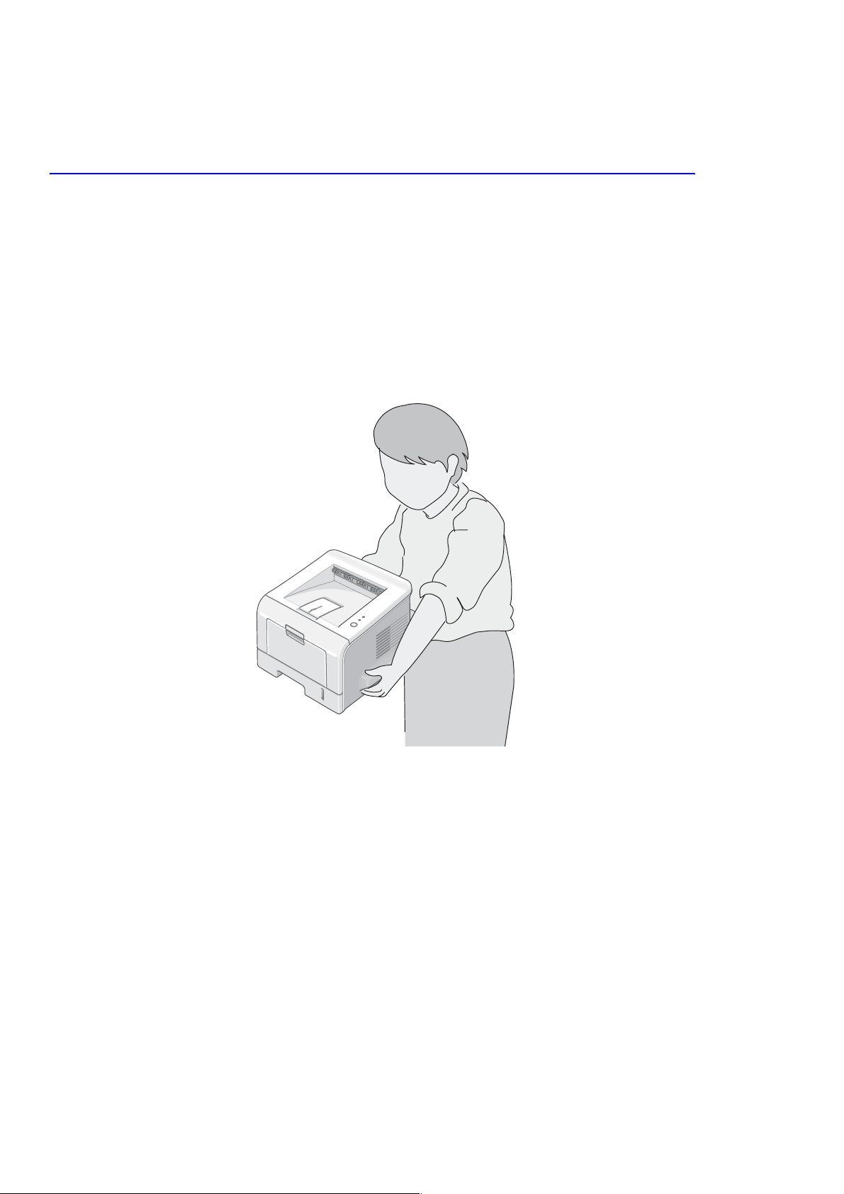
3. When you moving the printer.
This printer weighs 12.7 kg including the toner cartridge and tray. Use safe lifting and handling techniques. Use
the lifting handles located on each side of the printer. Back injury could result if you do not lift the printer
properly.
4. Ensure the printer is installed properly.
Ensure the printer is installed on a flat, level surface, capable of supporting its weight. Failure to do so could
cause the printer to tip or fall possibly causing personal injury or damaging the printer.
Do not install the printer on a sloping or unstable surface. After installation, double check that the printer is
stable.
1-4
Page 12

Precautions
1.3 ESD Precautions
Some semiconductor components, and the respective sub-assemblies that contain them, are vulnerable to damage by
Electro-Static DISCHARGE (ESD). These components include Integrated Circuits (ICs), Large-Scale Integrated
circuits (LSIs), field-effect transistors, and other semiconductor chip components. The following techniques will
reduce the occurrence of component damage caused by static electricity.
Be sure the power is off to the chassis or circuit board, and observe all other safety precautions.
■ Immediately before handling any semiconductor components assemblies, drain the electrostatic charge from
your body. This can be accomplished by touching an earth ground source or by wearing a wrist strap device
connected to an earth ground source. Wearing a wrist strap will also prevent accumulation of additional bodily
static charges. Be sure to remove the wrist strap before applying power to the unit under test to avoid potential
shock.
■ After removing a static sensitive assembly from its anti-static bag, place it on a grounded conductive surface. If
the anti-static bag is conductive, you may ground the bag and use it as a conductive surf ace.
■ Do not use freon-propelled chemicals. These can generate electrical charges sufficient to damage some devices.
■ Do not remove a replacement component or electrical sub-assembly from its protective package until you are
ready to install it.
■ Immediately before removing the protecti ve material from the leads of a replac ement de vice, touch the protecti v e
material to the chassis or circuit assembly into which the device will be installed.
■ Minimize body motions when handling unpackaged replacement devices. Motion, such as your clothes brushing
together, or lifting a foot from a carpeted floor, can generate enough static electricity to damage an electrostatically sensitive device
■ Handle IC’s and EPROM’s carefully to avoid bending pins.
■ Pay attention to the direction of parts when mounting or inserting them on Printed Circuit Boards (PCB’s).
Service Manual 1-5
Page 13

Precautions
1-6
Page 14

Reference Information
Reference Information
2
This section contains a tools list, list of abbreviations used in this manual, and a clearance required specification when
installing the Phaser 3150 printer.
2.1 Tools for Troubleshooting the Printer
The following tools are recommended for safe and easy troubleshooting as described in this service manual.
■ Digital Voltage Meter (DVM) standard: indicating more than 3 digits
■ Screwdrivers
■ Tweezers
■ Cotton swabs
■ Cleaning equipment: dry, lint-free cloth and/or mild detergent
■ Toner Type II Vacuum
■ Soft bristle brush
■ Printer Installer and Utilities CD-ROM
■ Diagnostic Control Unit (DCU)
Service Manual 2-1
Page 15

Reference Information
2.2 Acronyms and Abbreviations
Definition Definition
ADC Analog-to-Digital Conversion F/W Firmware
AP Access Point FCF/FCT Tray 1 or First Cassette Feeder
AC Alternating Current FISO Front In, Side Out
ASIC Application Specific Integrated Circuit FPOT First Print Out Time
Ass’y Assembly GDI Windows Graphic Device Interface
BIOS Basic Input Output Sytem GIF Graphic Interchange Format
BLDC Motor Brushless Dc Motor GND Ground
CMOS Complementary Metal Oxide
Semiconductor
CMYK Cyan, Magenta, Yellow, Black HDD Hard Disk Drive
CN Connector HTML Hyper-text Transfer Protocol
CON Connector HV High Voltage
CPU Central Processing Unit HVPS High Voltage Power Supply
CTD Sensor Color Toner Density Sensor I/F Interface
dB Decibal I/O Input/Output
dBA A Weighted Decibel lb Pound(s)
dBm Decibel Milliwatt IC Integrated Circuit
DC Direct Current ICC International Color Consortium
DCU Diagnostic Control Unit IDE Intelligent/integrated Drive Electronics
DIMM Dual In-line Memory Module IEEE Institute of Electrical and Electronics
DPI Dots Per Inch IOT Image Output Terminal (Color Printer,
DRAM Dynamic Random Access Memory IPA Isopropyl Alcohol
HBP Host Based Printing
Engineers, Inc.
Copier)
DVM Digital Voltmeter IPC Inter Process Communication
ECP Enhanced Capability Port IPM Images Per Minute
ECU Engine Control Unit ITB Image Transfer Belt (Transfer Belt)
EEPROM Electronically Erasable
Programmable Read Only Memeory
EMI Electro Magnetic Interference LBP Laser Beam Printer
EP Electro Photographic LCD Liquid Crystal Display
EPP Enhanced Parallel Port LED Light Emitting Diode
LAN Local Area Network
LSU Laser Scanner Unit
2-2
Page 16

Reference Information
Definition Definition
LVPS Low Voltage Power Supply Or SMPS
MB Megabyte Q’ty Quantity
MHz Megahertz RAM Random Access Memory
MPBF Mean Prints Between Failure ROM Read Only Memory
MPF/MPT Multi-Purpose Tray SCF/SCT Tray 2 Or Second Cassette Feeder
NIC Network Interface Card SMPS Switching Mode Power Supply or LVPS
NPC Network Printer Card SPGPm Samsung Printer Graphic Processor
NVRAM Non-volitale Random Access Memory SPL Samsung Printer Language
OPC Organic Photo Conductor Spool Simultaneous Peripheral Operation Online
PBA Print Board Assembly SW Switch
PCI Peripheral Component Interconnect SURF Surface Rapid Fusing
PCL Printer Command Language Sync Synchronous
PDF Portable Document Format T1 ITB or Transfer Belt Imaging
PDL Page Description Language T2 Transfer Roller Imaging
Ping Packet Internet or Inter-network
Grouper
PPD PostScript Printer Description PnP Universal Plug-n-Play
PPM Pages Per Minute URL Uniform Resource Locator
PS PostScript USB Universal Serial Bus
PTL Pre-Transfer (Erase) Lamp
PWM Pulse Width Moduration
TRC Toner Reproductive Curve
Service Manual 2-3
Page 17
Reference Information
(
)
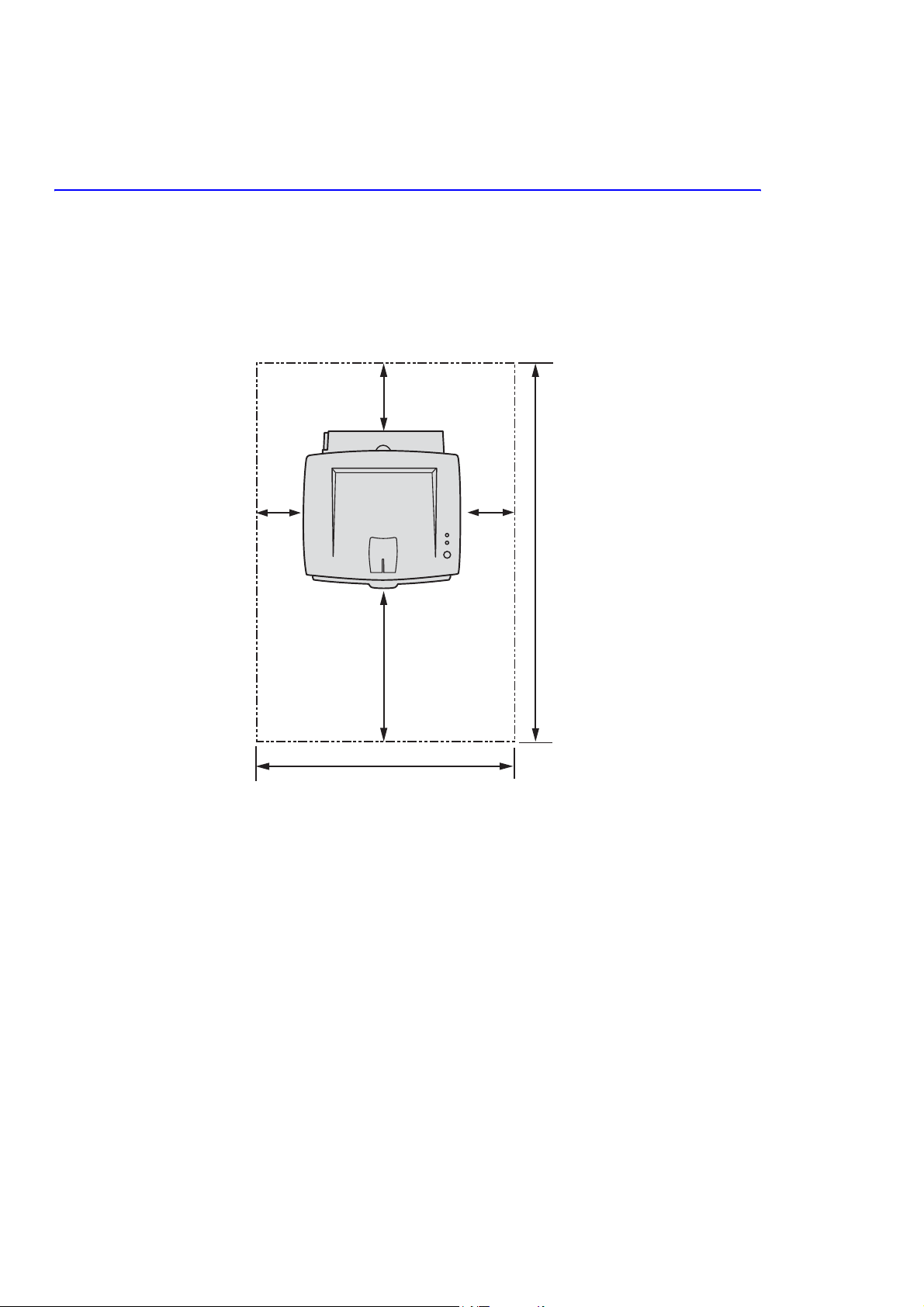
2.3 Selecting a Location for the Printer
■ Leave enough room to open the printer trays, covers, and allow for proper ventilation.
■ Provide the proper environment:
■ A sturdy, level surface.
■ Away from the direct airflow of air conditioners, heaters, or ventilators.
■ Free from extreme fluctuations in temperature, sunlight, or humidity.
■ Clean, dry, and free from excessive dust.
100 mm
(3.9 in.)
100 mm
(3.9 in.)
482.6 mm(18.8 in.)
552 mm(21.7 in.)
100 mm
(3.9 in.)
37.5 in.
954.6 mm
2-4
Page 18

Specifications
Specifications
3
The specifiations in this manual are correct at the time of printing. Product specifications are subject to change
without notice.
3.1 General Specifications
Item Description
Print Method Laser diode unit and electrophotography
Developing system Non-magnetic, contacting development system
Exposure System Semiconductor laser diode beam scanning
Fuser (toner fixing) Thermal rollers fusing with pressure (heat lamp: 600 Watts)
Resolution True: 600 x 600 dpi
Addressable: 1200 x 1200 dpi
Grayscale level: 128 Gray
Print Speed* A4: 20 ppm
Letter/Executive: 22 ppm
Legal: 18 ppm
Warm-up time Cold warm-up and sleep mode: 42 seconds
FPOT <
Feed Method Tray 1/MPT (Multi-Purpose Tray), Tray 2 (Cassette), Optional Tray 3, 250-sheet
Dimensions Width: 358 mm (14.1 in.)
Weight Printer: 10.2 kg (22 lb.) with consumables
Acoustic Noise** Standby: 39 dBA
10 seconds
feeder
Depth: 452 mm (17.8 in.)
Height: 278 mm (10.9 in.)
Optional Tray 2: 3 kg (6.6 lb.) with packaging
Printing: 53 dBA
Power Saver Mode Available, user settings enabled
* Print speed will be affected by the operating system used, computing performance, application
software, connection method, media type, media size, and job complexity.
** Sound pressure level, ISO 7779
Service Manual 3-1
Page 19

Specifications
3.2 Controller/Software Specifications
Item Description
Processor SPGPM (Samsung Printer Graphic Processor) 166 MHz
Memory 32 MB, expandable to 144 MB, SDRAM
Emulation SPL, PCL6 (Firmware), Epson, IBM Proprinter, Optional PostScript 3
SPL, PCL6 (Firmware), KS5843, KSSM, KSC5895
Interface Standard: IEEE1284, USB 2.0
Auto Interface sensing
Font Flash memory, 45 scalable, 1 bitmap
Network Optional: 10/100 Base TX
Test Print Demo Mode: Press the Cancel key for 2 seconds.
Configuration Mode: Press the Cancel key for 6 seconds.
Cleaning Mode: Press the Cancel key for 10 seconds.
Operating System
Compatibility
Windows 98/NT4/2000/Me/XP
Linux OS including Red Hat, Caldera, Debian, Mandrake, Slakware, SuSE, and
Turbo Linux
3.3 Electrical Specifications
Item Description
Input Voltage Low voltage: 100-127 VAC High voltage: 220-240 VAC
Input Range 90-135 VAC 180-270 VAC
Input Frequency: 50/60 Hz 50/60 Hz
Frequency tolerance +
Power Consumption Ready: 70 Watts
Power Saver Mode User settings available Off or 5, 10, 15, 30, 45, and 60 min.
3 Hz +3 Hz
Average: 400 Watts
Maximum: 700 Watts
Power Saver: 15 Watts
3-2
Page 20

3.4 Environmental Range
Items Operating Storage Optimum
Specifications
Temperature
Humidity 10 - 80% RH 20 - 95% RH 30 - 70% RH
Altitude 2,500 meters (8,200 feet)
10 ~ 32
o
C (50 ~ 90oF) 0 ~ 40 oC (32 ~ 104oF) 20 - 25oC
3.6 Media Specifications
3.6.1 Approved Paper Size and Weights
The supported media types for this printer include, but are not limited to: labels, envelopes, cardstock, plain paper,
transparency, letterhead and colored paper.
Tray Support Media Types / Capacity Sizes Weight
Tray 2
Optional Tray 3
Tra y 1 / M P T
Plain Paper - 250 sheets A4, A5, A6, Letter, Legal, Folio,
Oficio, Executive, ISO and JIS B5
Plain Paper - 50 sheets
OHP film, Label
Envelope -10
Card stock;
Custom
A4, A5, A6, Letter, Legal, Folio,
Oficio, Executive, ISO and JIS B5
Monarch No. 10, C5, C6, DL
International Postcard, Letter/A4
Min. 75 x 125 mm
16 ~ 24 lb.
60 ~ 90 g/m
16 ~ 43 lb.
60 ~ 163 g/m
2
2
3.6.2 Print Margins and Skew
Print Area Margin
Guaranteed
Print Quality Area
Printable area Paper Width (A+B)
Registration Tolerance +
Skew Tray 1, 2 Tray 3 Length
A. Vertical Skew < 2.0 mm (0.08 in.) < 2.5 mm (0.10 in.) 244.3 mm
B. Horizontal Skew < 1.5 mm (0.06 in.) < 2.0 mm (0.08 in.) 177.8 mm
Paper Width (A+B)
Paper Length (C+D)
Paper Length (C+D)
2.5 mm in the scan direction
+
3.0 mm in the process direction
A = Left Margin
B = Right Margin
C = Top Margin
D = Bottom Margin
A = Left Margin
B = Right Margin
C = Top Margin
D = Bottom Margin
Service Manual 3-3
4.23 mm
4.23 mm
4.23 mm
4.23 mm
3 mm
3 mm
3 mm
3 mm
Page 21

Specifications
3-4
Page 22

Product Summary
4
This section describes the functions and operating principals of the printers main components.
4.1 Printer Components
4.1.1 Front View
Top output tray
(Face down)
Control Panel
Output Support
Summary of Product
Front Cover
Multi Purpose Feeder
Tray
Power switch
Paper level indicator
Service Manual 4-1
Page 23

Summary of Product
4.1.2 Rear View
Power
Receptacle
Rear Output Tray
(Face up)
USB Port
Top Output Tray
(Face down)
4.1.3 Control Panel
Parallel Port
4-2
Page 24

ON Line/Error and Toner Save LED’s
LED Description
The On Line/Error LED is green, when the printer is Ready to Print.
The On Line/Error LED slowly blinks green when the printer is receiving data,
and blinks rapidly while printing.
The On Line/Error LED is red if an error occurs in the printer.
The On Line/Error LED will blink red if:
■ The user presses the Cancel button to cancel a print job.
■ The printer is in manual feed mode and there is no paper in the
If the On Line/Error LED is blinking red and orange alternately the printer has
detected a non-Xerox toner cartridge.
If the installed toner cartridge is empty the On Line/Error LED blinks orange
and the toner cartridge needs to be replaced.
Summary of Product
Tray1/MPT.
If the On Line/Error and Toner Save LEDs all blink at the same time, an
internal or hardware malfunction is present.
Refer to Section 6.6 for troubleshooting procedures.
The Toner Save LED comes on when Toner Save mode is enabled. This can be
set in the printer driver.
Cancel Button Functions
Printing the Demo Page In Ready mode, press and hold the Cancel button until all LEDs blink slowly
and then release, (approximately 2 seconds).
Printing the
Configuration Page
Cleaning inside the
printer
Canceling a print job To cancel a print job, press the Cancel button.
In Ready mode, press and hold the Cancel button until all LEDs blink quickly
and then release, (approximately 6 seconds).
In Ready mode, press and hold the Cancel button until all LEDs turn on and
then release (approximately 10 seconds).
After cleaning, one cleaning sheet is printed.
The On Line/Error LED blinks while the print job is cleared from both the
printer and the computer. The printer then returns to Ready mode. This may
take some time depending on the size of the print job.
NoteNoteNote
In Manual Feed mode it is not possible to cancel the print job by pressing
this button.
Service Manual 4-3
Page 25

Summary of Product
4.2 Printer Theory of Operation
4.2.1 System Summary
The printer consists of the following main functional components:
1) The Firmware
Engine firmware controls the whole printing process.
2) The Print Engine
1. Engine Frame
2. Paper Feed
The paper feed system consists of a 250-sheet main paper tray (Tray 2), a multi-purpose paper tray (Tray 1),
pickup rollers, friction pads, and feed rollers. The rollers and sensors in the paper feed path control paper
registration and guide the paper through the image transfer, image development, image fusing and exit
assemblies. The paper path has an anti-static connection to ground to eliminate problems due to static charge on
the paper.
3. Main drive mechanism
The main drive is a bi-polar, two phase motor. It drives the drum, paper pick, and paper feed rollers using a gear
train mechanism.
4. Image development unit
Using a Laser Scanner Unit (LSU), this portion of the mechanism creates the image on the OPC drum (part of the
integrated toner cartridge).
5. Image transfer unit
This unit uses the high voltages supplied by the HVPS to move the image from the OPC drum onto the paper.
6. Image fusing unit
This unit permanently fixes the toner image onto the paper. This is achieved using a temperature controlled
heating unit (the fuser).
7. Electronic boards include:
a. The Main control board, consisting of:
■ Main processor asic (166 MHz SPGPm)
■ Memory (Flash ROM containing the control program and DRAM for working memory)
■ Engine interface parts (motor control, fuser control, HVPS control, and sensors)
■ PC Interface (USB , Parallel, Network)
■ Bus, DMA and I/O handling
b. Control panel
c. PC Interface
4-4
Page 26

4.2.2 System Layout
Summary of Product
5
L S U
4
Fuser
EXIT
Sensor
CR
6
PR
OPC
TR
3
Toner Cartridge
DR
SR
FR
MP SensorMP Sensor
R
/
K
C
I
P
2
1
1
Cassette
Manual Feeder
2
Transfer Roller
3
4
Fuser
LSU(Laser Scan Unit)
5
Toner Cartridge
6
4.2.3 Paper Feed
The paper feed system consists of a 250- sheet main paper tray (Tray 2), a multi-purpose paper tray (Tray 1), pickup
rollers, friction pads and feed rollers. The rollers and sensors in the paper feed path control paper registration and
guide the paper through the image transfer, image de velopment, image fusing and e xit assemblies. The paper path has
an anti-static connection to ground to eliminate problems due to static charge on the paper.
1. Paper separation method
Individual sheets are separated in the tray using the ‘friction pad’ method. When paper feeds into the printer it
passes over a spring loaded friction pad that separates the sheets of paper.
2. Paper tray (cassette)
The paper trays use a ‘center loading’ method. There are no paper size sensors, instead a software process is used
to detect the size of the first sheet of paper as it is fed through the printer. Both the rear and side paper guides are
adjustable for various paper sizes.
There is a ‘Paper Empty’ sensor which detects the presence of paper (Capacity: 250 sheets).
There is an indicator flag on the front of the tray which indicates the amount of paper remaining.
3. Pick-up roller
The pick-up roller is used to pick and feed paper into the printer. It also is used to remove an y static charge on the
paper.
4. Tray1/MPT
The multi-purpose tray is used to hold non-standard or custom paper sizes and special media (envelopes,
transparencies, etc.). There is an MPT paper empty sensor. The MPT uses a friction pad method to ensure paper
separation and can hold a maximum of 50 sheets of paper or envelopes.
5. SCF (Second Cassette Feeder) or Tray 3
The optional third tray unit is universal with the second main tray and also has a capacity of 250 sheets.
Service Manual 4-5
Page 27

Summary of Product
4.2.4 Transfer Assembly
The transfer roller transfers toner from the OPC drum to the paper. Toner is transferred from the OPC drum onto the
paper using a PTL (Pre-Transfer Lamp) and a transfer roller. The PTL shines light onto the OPC, reducing the
electrical charge on the OPC surface improving the effi ciency of the transfer.
The transfer assemblies life span is 60,000 sheets.
4.2.5 Drive Assembly
The drive assembly receives power from the main controller board. The main motor powers the paper feed, toner
cartridge, fuser unit and all pick-up, feed, and exit rollers.
4.2.6 Fuser Assembly
The fuser assembly uses a heat lamp process. This consists of a heat lamp, heat roller, pressure roller , thermistor, and
thermostat. By use of heat and pressure, toner is melted to adhere to the paper surface in order to complete the
printing process.
4.2.6.1 Thermistor and Thermostat
The thermistor is used to detect the temperature of the heating unit and feeds this information into the main processor.
If the heat lamp becomes too hot, the thermostat cuts off the power to the lamp in order to prevent overheating and
any potential fire hazard is removed.
4.2.6.2 Heat roller
The heat roller transfers the heat from the heat lamp to the paper. The surface of the heat roller is coated with Teflon
so that toner does not stick to the surface.
4.2.6.3 Pressure roller
A pressure roller, mounted under the heat roller, is made of a silicon resin and the surface is also coated with Teflon.
When paper passes between the heat roller and the pressure roller the toner powder is melted and permanently fixed
to the surface of the paper.
4.2.6.4 Safety features
To prevent overheating:
■ 1st protection device: Hardware cuts off when overheated.
■ 2nd protection device: Software cuts off when overheated.
■ 3rd protection device: Thermostat cuts off main power to the lamp.
Safety device
■ Fuser power is cut off when the front cover is opened.
■ Laser power is cut off when the front cover is opened.
■ The temperature of the fuser cover's surface is maintained at less than 80º C to protect the user. A caution
label is attached where the customer can see it easily when the rear cover is opened.
4-6
Page 28

Summary of Product
4.2.7 Laser Scanner Unit (LSU)
This is the core of the laser printer. It converts the video data received from the computer into an electrostatic latent
image on the surface of the OPC drum. This is achieved b y controlling the laser beam and e xposing the surf ace of the
OPC drum to the laser light. A rotating polygon mirror reflects the laser light onto the OPC. Each face of the mirror
produces one scan line. As the OPC drum turns, the laser scans, to create the full page image.
The HSYNC signal is created when the laser beam from the laser unit reaches the end of the polygon mirror and this
signal is sent to the controller. The controller detects the HSYNC signal to adjust the vertical line of the image on
paper. In other words after the HSYNC signal is detected the image data is sent to the laser unit to adjust the left
margin on the paper.
4.2.8 Toner Cartridge
The toner cartridge is an integral unit containing the OPC unit and toner unit. The OPC unit consists of the OPC drum
and charge roller. The toner cartridge unit consists of the toner, supply roller, developing roller, and blade (doctor
blade).
Developing Method Non magnetic 1 element contacting method
Toner Non magnetic 1 element shatter type toner
Toner Life 3,500 sheets / 5,000 sheets (ISO19752 standard)
Toner remaining sensor No
OPC Cleaning Film OPC using an electro-static cleaning process
Management of waste toner Collected using an electro-static process and retained within the toner
cartridge. No waste toner to dispose of.
OPC Drum protecting Shutter No
Toner CRUM Reader Identifies whether toner is Xerox branded toner or whether a Non-Xerox toner
cartridge is installed in the printer
Service Manual 4-7
Page 29

Summary of Product
4.3 Main Controller Board (PBA)
The engine board and controller board have been integrated into a single board consisting of the CPU and printer
control functions. The CPU functions as the bus controller, I/O handler, motor driver and PC interface. The main
board sends the current image video data to the laser unit and manages the electrophotographic printing process.
Circuits on the main board drive the main motor (paper feed, cartridge, fuser), clutch, pre-transfer lamp, heat-lamp
and fan. The signals from the paper feed jam sensor and paper empty sensor are inputted to the main board from the
power supply board.
1 2 3 4
17
16
15
8
8
11121314
910
7
1. U1 Low drop fixed and adjustable positive voltage regulators (LD1117DT)
2. U2 Low power, dual bi-polar comparators (LM393D)
3. U4 Spread spectrum clock generator (CY25811)
4. OSC1 CPU X-TAL (12 MHz)
6
5
5. U6, U15 SDRAM (K4S641632H)
6. U7 Low voltage HEX inverter with 5 V tolerant Schmitt trigger inputs (74LCX14)
7. U9 Motor driver (A3977SLP)
8. U11 Graphics processor ASIC (SPGPm)
9. U24 Low voltage HEX inverter with 5V tolerat Schmitt trigger inputs (74LCX14)
10. U23 Parallel port single termination network (ST1284)
11. U22 Low voltage IEEE translating transceiver (161284)
12. OCS3 Video X-TAL (19.6 MHz)
13. U25 USB 2.0 (NET2270)
14. OSC4 USB X-TAL (30 MHz)
15. U14, U19 Low voltage octal D-type flip-flop (74LVX273)
16. U10 Low voltage, bi-directional transceiver (74LCX245)
17. U13 Flash Memory (29LV160DB)
4-8
Page 30

4.3.1 ASIC (SPGPm)
■ ARM946ES
■ 32-bit RISC embedded processor core
■ 16 KB instruction cache and 16 KB data cache
■ No tightly coupled memory
■ Memory protection unit and CP15 control program
■ Dual bus architecture for bus traffic distribution
■ AMBA high performance bus (AHB)
■ System bus with SDRAM
■ IEEE1284 compliant parallel port interface
■ Printer Video Controller for LBP engines
■ Graphic Execution Unit for banding support of printer languages
■ Printer Video Controller for LBP engines
■ PVC: Printer Video Controller without RET Algorithm
■ HPVC: Printer Video Controller with RET algorithm
(Line Memory and Lookup Table Memory: 512 x 8, 4096 x 16)
■ Engine Controller
■ Motor control unit
■ Motor speed lookup table memory (128 x 16 x 2)
■ Pulse width modulation unit
■ 4 channels are supported
■ ADC interface unit
■ 3 ADC Channels are available
■ ADC Core (ADC8MUX8) maximum clock frequency: 3 MHz
■ USB 2.0 Interface
■ Package: 272 pins PBGA
■ Power: 1.8 V(Core), 3.3 V(IO) power operation
■ Speed: 166 MHz core (ARM946ES) operation, 60 MHz bus operation
Summary of Product
4.3.2 Memory
The board has Flash ROM and DRAM memory units. There are 2 SODIMM sockets to enable extra DRAM or Flash
ROM (PostScript option, not available in all countries) to be fitted.
4.3.3 Flash Memory
Flash memory stores the system software code. This can be updated by downloading the system program through the
PC Interface. PCL fonts are also stored in the flash memory.
■ Capacity: 2 MB
■ Access Time: 70 nsec
Service Manual 4-9
Page 31

Summary of Product
4.3.4 SDRAM
Used as a swath buffer, systems working memory area, etc. when printing.
■ Capacity: 32 MB, expandable up to 144 MB
■ Optional Additional DIMM : 16 MB / 32 MB / 64 MB /128 MB
■ Type : SDRAM 100 MHz/133 MHz, 16bit
4.3.5 Sensor Input Circuit
4.3.5.1. Paper Empty Sensing
The Paper Empty sensor (Photo Interrupter) on the engine board is monitored by the CPU. When the tray is empty the
printer flashes the red error LED.
4.3.5.2. Tray 1/MPT Sensing
Presence of paper in Tray 1 is detected by the MP sensor (photo interrupter) on the frame. The CPU monitors this
sensor to recognize paper in Tray 1, and paper is fed if there is paper present.
4.3.5.3. Paper Feeding
When paper passes the actuator on the feed sensor, it is detected by the photo interrupter. The CPU monitors the
signal and starts the process of creating the image after a specified delay time. If the feed sensor is not detected within
one second after paper is fed, a paper jam0 occurs. (red error LED is lit).
4.3.5.4. Toner Remaining Sensing
The printer does not have a toner remaining sensor.
4.3.5.5. Paper Exit Sensing
This detects that paper exits cleanly from the printer using an exit sensor on the engine board and actuator on the
frame. The CPU detects the on/off time of the exit sensor and normal operation or a jam status is reported. If a Jam2
error occurs, the red error LED is lit.
4.3.5.6. Cover Open Sensing
The cover open sensor is located on the power supply board. It is operated by a molded tab on the front cover. When
the front cover is open the +24 V and +5 V supplies to the DC fan, solenoid, main motor, polygon motor in the laser
unit, HVPS and laser diode are cut off.
4.3.5.7. DC Fan/Solenoid Driving Circuit
A fan driving circuit is controlled by the CPU via a transistor. It is automatically turned off when the printer enters
sleep mode. There are two solenoids, these are driven by signals from the CPU (tray paper pick).
4.3.5.8. Motor Driving Circuit
The main motor drives the paper feed, developing unit, fuser, and exit assembly. The circuit is driven by software
which controls the acceleration, constant speed, and deceleration profiles. The Motor is driven using an A3977 driver
IC.
4-10
Page 32

Summary of Product
4.3.5.9 Transfer
The charging voltage, developing voltage, and the transfer voltage are controlled by pulse width modulation (PWM).
Each output voltage is changeable according to the PWM duty cycle. The transfer voltage used when the paper passes
the transfer roller is decided by environment recognition. The resistance v alue of the transfer roller changes due to the
environment of the room or within the printer. This change in resistance in turn changes the value of the voltage due
to loading. This voltage is fed back into the printer through the A/D converter . Based on the value fed back the PWM
cycle is changed to maintain the required transfer voltage.
4.3.5.10 Fusing
The temperature of the heat roller's surface is detected according to the resistance value of the thermistor. The
thermistor resistance is measured using the A/D conv erter and thus the CPU can determine the temperature of the heat
roller. The AC power is controlled by comparing the target temperature to the value from the thermistor. If the value
from the thermistor is out of the controlled range while controlling the fusing process, an error is reported.
See the error table below to identify fuser temperatur errors.
Error Description DCU LED Display
Open heat error
Low heat error Standby:
Over heat error
Lower than 68
warming up.
Lower than 100
Printing:
From 2 consecutive pages; the fixed fusing
temperature has been lower than 30
than 5 seconds.
Higher than 220
It has been higher than 220
0
C for more than 25 seconds while
0
C for more than 20 seconds.
0
C for more
0
C for over 3 seconds.
0
C for over 3 seconds.
60 All LEDs blinking
62 All LEDs blinking
68 All LEDs blinking
4.3.5.11 Laser Scanner Unit (LSU)
The Laser Unit consists of the laser diode and the polygon motor control. When the printing signal occurs, the laser
diode is turned on and the polygon motor is enabled. When the light sensor detects the beam, H-SYNC occurs. When
the polygon motor speed becomes steady, Ready mode occurs. If these two conditions are satisfied the laser unit is
judged to be ready. If the two conditions are not satisfied, one of two errors are reported as shown in the table below.
Error Description DCU
Polygon motor error When the polygon motor speed is not steady. 95
H-SYNC error The polygon motor speed is steady but the H-SYNC
is not generated.
96
Service Manual 4-11
Page 33

Summary of Product
4.4 Switching Mode Power Supply (SMPS) and High
Voltage Power Supply (HVPS)
The SMPS and HVPS are on one integrated board.
The SMPS supplies the DC power to the printer. It takes either 110 V or 220 V and outputs the +5 V and +24 V
supplies to the main board.
The HVPS creates the high voltage for the THV/MHV/Supply/Dev and supplies it to the toner cartridge. The CPU is
used to modify some of these voltage settings to provide the ideal voltages to create the image.
The HVPS uses the 24 V and outputs the high voltage for THV/MHV/BIAS and the outputted high voltage is then
supplied to the toner, OPC cartridge, and transfer roller.
4-12
Page 34

4.4.1 High Voltage Power Supply
1) Transfer High Voltage (THV+)
Input Voltage: 24 VDC ± 15%
Output Voltage: MAX +5.0K V ± 5%, (duty variable, no loading
1.2 KV ±15% (when cleaning, 200 M
Output Voltage Trigger: 6.5 uA
Input contrast of the Voltage stability degree :under ± 5 % (fluctuating input 21.6 V~26.4 V)
Loading contrast : ± 5% or less
Output Voltage Rise Time: 100 ms Max
Output Voltage Fall Time: 100 ms Max
Transfer voltage range as environment varies: +650 V(Duty 10%) ~ 5K V (Duty 90%)
Environment Recognition Control Method:
The THV-PWM ACTIVE is the transfer active signal. It detects the resistance by recognizing the voltage
value, F/B, while permitting the environmental recognition voltage.
Output Voltage Control Method:
Transfer output voltage is output and controlled by changing the duty cycle of the THV PWM Signal.
10% duty: +650 V; 90% duty: +5K V±5%
Summary of Product
2) Charge Voltage (MHV)
Input Voltage: 24 VDC ± 15%
Output Voltage: -1.3K V ~ -1.8K VDC ± 50V
Output Voltage Rise Time: 50 ms maximum
Output Voltage Fall Tim: 50 ms maximum
Output Loading range: 30 Mž ~1000 Mž
Output Control Signal (MHV-PWM): CPU is HV output when PWM is low
3) Cleaning Voltage (THV-)
The (+)Transfer Voltage is not output because the THV PWM is controlled with high.
The (-)Transfer Voltage is output because the THV-Enable Signal is controlled with low.
The output fluctuation range is big because there is no Feedback control.
4) Developing Voltage (DEV)
Input Voltage: 24 VDC ± 15%
Output Voltage: -200 V ~ -600 VDC ±20V
Output Voltage Fluctuation range: PWM Control
Input contrast of the output stability degree: ±5 % or less
Loading contrast: ± 5 % or less
Output Voltage Rise Time: 50 ms maximum
Output Voltage Fall Time: 50 ms maximum
Output Loading range: 10 Mž ~ 1000 Mž
Output Control Signal (BIAS-PWM): the CPU output is HV output when PWM is low.
Service Manual 4-13
Page 35

Summary of Product
5) Supply
Output Voltage: -400 V ~ -800 VDC ±50 V (ZENER using, DEV)
Input contrast of the output stability degree: under ±5%
Loading contrast: ±5% or less
Output Voltage Rise Time: 50 ms maximum
Output Voltage Fall Time: 50 ms maximum
Output Loading range: 10 Mž ~ 1000 Mž
Output Control Signal (BIAS-PWM): the CPU is HV output when PWM is low.
4.4.2 Switching Mode Power Supply
The SMPS is the power source for the entire printer system. The SMPS supplies DC power for driving the printer , and
the AC heater control which supplies power to fuser. The SMPS has two output channels: 3.3 V and +24 V.
1) AC Input
Input Rated voltage: AC 220 V ~ 240 V, AC 120 V ~ AC 220 V (EXP version)
Input Voltage range: AC 198 V ~ 264 V, AC 90 V ~ 135 V, AC 198 V ~ 264 V (EXP version)
Rated Frequency: 50/60 Hz
Frequency range: 47 ~ 63 Hz
Input Current: Under 4.0A RMS/2.0A RMS (When the fuser lamp is off and input / output voltages are in range)
2) Rated Output Power
No Item CH1 CH2 CH3 Remark
Channel name +3.3 V +5 V +24.0 V
1.
CONNECTOR PIN CON 3
2.
3.3 V PIN: 3, 4
GND PIN: 5, 6
Rated output 3.3 V ± 5%
3.
(3.2 ~ 3.4 V)
Max output current 1.0 A 0.14A 2.0 A
4.
Peak loading current 1.5 A 0.14A 2.5 A 1ms
5.
Ripple noise voltage Under 100mVp-p 100mVp-p Under 500mVp-p
6.
Maximum output 3.3 W 0.35 W 48 W
7.
Peak output 4.95 W 0.7 W 60 W 1ms
8.
Protection for loading
9.
shortage and overflowing
current
--
CON 3
5 V PIN: 8
GND PIN: 7
+5 V ± 5%
(4.75 ~ 5.25 V)
CON 3
24 V PIN: 11, 12, 13
GND: 9, 10
+24 V ± 10%
(21.6 ~ 26.4 V)
3) Consumption Power
No Item CH1 +3.3 V CH2 +5 V CH3 +24.0 V Remark
Standby 1.0 A 0.07 A 0.4 A AVG: 55 Wh
1.
Printing 1.0 A 0.14 A 2.0 A AVG: 280 Wh
2.
4-14
Page 36

Summary of Product
4.5 Engine F/W
4.5.1 Feeding
While feeding from the universal trays, the drive for the pickup roller is controlled by the pick-up solenoid. The
printer feeds the paper from the Tray1/MPT according to the information provided by the MP sensor, and by driving
the main motor, insert the paper in front of the feed sensor.
Jam Description
This is an indcation that the leading edge of the paper did not pass the feed sensor.
■ After paper pick, paper does not enter the printer.
■ After paper pick, the paper enters the printer but it does not reach the feed sensor in the
Jam 0
Jam 1
specified amount of time.
■ If paper has been picked, and the feed sensor is not ON, the printer will re-pick. If after re-
picking the feed sensor is still not reported as ON, this error will occur.
■ Even though the paper reaches the feed sensor, the feed sensor is not ON.
This is an indication that the leading edge of the paper has already passed the feed sensor.
■ After the leading edge of the paper passes the feed sensor, the trailing edge of the paper
does not pass the feed sensor within the specified time. (The feed sensor cannot be OFF
during this time.)
■ After the leading edge of the paper passes the feed sensor, the paper does not reach the exit
sensor within the specified time. (The exit sensor cannot be ON during this time.)
Jam 2
The paper is between the feed sensor and the exit sensor.
■ After the trailing edge of the paper passes the feed sensor, the trailing edge of the paper does
not pass the exit sensor within the specified time.
Service Manual 4-15
Page 37

Summary of Product
4-16
Page 38

Disassembly
Disassembly
5
5.1 Precautions for Disassembly/Reassembly
■ Use only approved Xerox spare parts. Ensure that the part number, product name, any voltage, current or
temperature ratings are correct. Failure to do so could result in damage to the printer, circuit overload, fire or
electric shock.
■ Do not make any unauthorized changes or additions to the printer, this could cause the printer to malfunction and
create electrical shock or fire hazards.
■ When disassembling the printer, note where each screw goes. Using the wrong scre w could lead to printer failure,
short circuits, or electrical shock.
■ Do not disassemble the laser unit. Once it is disassembled dust is admitted to the mirror chamber and will
seriously degrade print quality. There are no serviceable parts inside.
■ Regularly check the condition of the power cord, plug and socket. Bad contacts
could lead to overheating and fire. Damaged cables could lead to electric shock or
component malfunctions.
Caution
Many of the parts are held in place with plastic latches. The latches break easily;
Remove them carefully. To remove such parts, gently pull the hook end of the
latch away from the part where it is latched.
Caution
To prevent damaging the toner cartridge and degrading print quality, protect the toner cartridge from light when
removing it from the printer.
5.1.1 Precautions When Removing Circuit Boards
Static electricity can damage a board, follow the ESD precautions in Section 1 of this manual when handling or
storing a board.
Precautions when moving and storing boards:
■ Place boards in an approved anti-static discharge bag.
■ Do not store a board where it is exposed to direct sunlight.
Precautions when replacing boards:
■ Disconnect power connectors first, before disconnecting other cables.
■ Do not touch any soldered connections, connector terminals, or other electronic parts when handling
insulated parts.
Precautions when checking boards:
■ Before touching a board, touch a grounded area on the printer chassis to discharge any static electrical
charge on the body or wear an anti-static wrist strap.
Service Manual 5-1
Page 39

Disassembly
■ Do not touch the board with your bare hands or metal objects, this can create a short circuit or cause an
electrical shock. Take extra care when handling boards containing sensors, motors or lamps as they may get
hot.
■ Take care when fitting, or removing, screws. Check for hidden screws. Always ensure that the correct screw
is used. When toothed washers are removed, ensure they are refitted in their original positions
5-2
Page 40

5.2 Front Cover
1. Remove the paper tray.
2. Open the front door and remove the toner cartridge.
Disassembly
Cassette
Front Cover
3. With the front cover fully open, carefully release the plastic hinge supports from the guide hooks by pulling
inward.
4. Pull the front cover away from the printer to remove.
A
Latch
Front Cover
Latch Holder
Service Manual 5-3
Page 41

Disassembly
5.3 Tray 1/MPT Assembly
1. Open the Tray1/MPT assembly.
o
2. With the tray at a 45
3. Lift the Tray1/MPT assembly off the hinge pins on the front cover.
angle, carefully release the plastic hinge supports from the guide hooks.
5-4
45°
Page 42

5.4 Rear Cover
Note
When disassembling the rear cover, move the power switch to the OFF position. When reassembling the rear
cover, move the power switch to the ON position.
1. Remove 2 screws securing the rear open cover and remove.
Rear Open
Disassembly
2. Open the face up cover.
3. Remove the 2 screws as shown below.
4. Using a screwdriver, carefully release the 2 tabs securing the rear cover.
Rear Cover
Service Manual 5-5
Page 43

Disassembly
5.5 Top Cover
1. Remove the front cover, see "5.2 Front Cover" on page 5-3.
2. Remove the rear cover, see "5.4 Rear Cover" on page 5-5.
3. Remove 4 screws securing the top cover as shown below.
Caution
When removing the top cover, lift the front of the top cover slowly to avoid damaging the exit rollers.
Use caution to avoid damaging the exit rollers when reassembling the top cover.
Exit Roller
5-6
Page 44

5.6 Middle Cover
1. Remove the rear cover, see "5.4 Rear Cover" on page 5-5.
2. Remove the top cover, see "5.5 Top Cover" on page 5-6.
3. Open the front cover.
4. Remove 4 screws securing the middle cover.
5. Disconnect and free the wiring harness from the middle cover.
6. Lift up on the left side of the middle cover to release it from the retaining pin.
Middle Cover
Disassembly
Service Manual 5-7
Page 45

Disassembly
5.7 Side Cover (Left and Right)
1. Remove the front cover, see "5.2 Front Cover" on page 5-3.
2. Remove the rear cover, see "5.4 Rear Cover" on page 5-5.
3. Remove the top cover, see "5.5 Top Cover" on page 5-6.
4. Remove the 2 screws securing the right or left cover.
5. Slide the cover towards the rear of the printer while releasing the top latch, as shown below, to remove the right
or left cover.
Side Cover(LH)
Bottom
Latches
Top Latch
Top Latch
5-8
Side Cover(RH)
Bottom Latches
Page 46

5.8 Exit Roller
1. Remove the front cover, see "5.2 Front Cover" on page 5-3.
2. Remove the rear cover, see "5.4 Rear Cover" on page 5-5.
3. Remove the top cover, see "5.5 Top Cover" on page 5-6.
4. Remove the left and right covers, see "5.7 Side Cover (Left and Right)" on page 5-8.
5. Remove the exit gear, bearing and exit roller as shown below
Note
It is not necessary to remove the laser unit or middle cover, although the image below shows them
removed from the printer.
Exit Gear Bearing
Disassembly
Service Manual 5-9
Page 47

Disassembly
5.9 Engine Shield Assembly and Exit Board
1. Remove the rear cover, see "5.4 Rear Cover" on page 5-5.
2. Remove the top cover, see "5.5 Top Cover" on page 5-6.
3. Remove the right cover, see "5.7 Side Cover (Left and Right)" on page 5-8.
4. Remove the paper tray.
5. Remove 1 screw securing the SMPS shield and remove the shield.
SMPS
Shield
w
Scre
6. Disconnect the following wiring harnesses from the SMPS; on the right side printer, the fan (CN3) and the
control panel (CN4). On the rear of the printer disconnect the fuser (CN1) and exit sensor (CN6).
7. Disconnect the following wiring harnesses connected to the main board.
CN 5 Laser Unit CN 10 Manual Solenoid
CN 6 Motor CN 11 PTL
CN 8 Pickup Sol CN 17 MP sensor
CN 9 Regi Sol CN 18 CRUM
Caution
Be sure all 12 wiring harnesses are diconnected from the assembly.
Caution
In the next step you will be turning the printer over, use caution when working on the printer in
order to avoid damaging the exit rollers.
5-10
Page 48

Disassembly
8. Turn the printer onto its top to access and remove the 12 screws on the bottom of the printer securing the engine
shield assembly.
Exit Board
Engine Shield Ass'y
9. Remove 2 screws securing the Exit Board to the print frame.
Caution
When reassembling the engine shield assembly, be sure the paper out sensor flag is up and out of
the way to avoid damaging the flag.
Service Manual 5-11
Page 49

Disassembly
5.10.1 SMPS
1. Remove the front cover, see "5.2 Front Cover" on page 5-3.
2. Remove the rear cover, see "5.4 Rear Cover" on page 5-5.
3. Remove the top cover, see "5.5 Top Cover" on page 5-6.
4. Remove the left and right covers, see "5.7 Side Cover (Left and Right)" on page 5-8.
5. Remove the engine shield assembly, see "5.9 Engine Shield Assembly and Exit Board" on page 5-10.
6. Remove the 3 screws (one is to ground) securing the inlet bracket and remove the bracket.
Inlet Bracket
7. Unplug 1 connector from the main board.
8. Remove the 6 screws securing the SMPS to the shield.
Connector
SMPS
5-12
Page 50

5.10.2 Main Board
1. Remove the rear cover, see "5.4 Rear Cover" on page 5-5.
2. Remove the SMPS shield, see step 5 in "5.9 Engine Shield Assembly and Exit Board" on page 5-10.
3. Disconnect all harnesses from the main board.
4. Remove the 8 screws securing the main board to the printer and remove the main board
Note
2 screws are securing the network card or plate.
Main PBA
Disassembly
Service Manual 5-13
Page 51

Disassembly
5.10.3 Removing the Network Card or Optional Memory
Modules
You only need to open the rear open cover to access the memory modules and network card.
Memory Board
Thumb Screws
5-14
Page 52

5.11 Fuser Assembly
Warning
The fuser assembly is HOT. Let the fuser cool before removing.
1. Remove the rear cover, see "5.4 Rear Cover" on page 5-5.
2. Unplug 2 connectors, one from the main board and one from the SMPS.
3. Remove 4 screws securing the fuser assembly.
Disassembly
Fuser Ass'y
Caution
When removing the thermostat, the 2 screws are secured by nuts that are not captured. These can
fall out and get lost if you tip the fuser assembly.
4. Remove the 2 screws securing the thermostat and lift the thermostat out.
Thermostat
Service Manual 5-15
Page 53

Disassembly
Caution
There are 2 securing nuts the screws go through that are not captured. These can fall out and get
lost when tipping the fuser assembly.
Caution
Hold the Halogen lamp by the end terminals. DO NOT TOUCH the lamp itself, this will damage it
and cause the fuser to malfunction.
5. Remove the 2 screws securing the Halogen lamp. Then remov e the lamp from the heat roller as shown below.
Halogen Lamp
Caution
When disassembling the fuser, note the orientation of the spring loaded stripper fingers (claws). If
reassembled improperly the claws will damage the heat roller causing the fuser to malfunction.
6. Remove the 4 screws securing the fuser cover and 2 screws securing the guide to disassemble the fuser.
Claw
Fuser Cover
5-16
Page 54

7. Free the thermister harness as shown below.
Disassembly
Thermistor Harness
8. Remove 1 screw securing the thermister and remove from the fuser assembly.
Thermistor
Service Manual 5-17
Page 55

Disassembly
5.12 Fan
1. Remove the front cover, see "5.2 Front Cover" on page 5-3.
2. Remove the rear cover, see "5.4 Rear Cover" on page 5-5.
3. Remove the top cover, see "5.5 Top Cover" on page 5-6.
4. Remove the right cover, see "5.7 Side Cover (Left and Right)" on page 5-8.
5. Disconnect the connector from the SMPS.
6. Remove 1 screw securing the fan.
Fan
5-18
Page 56

5.13 Laser Scanner Unit (LSU)
1. Remove the front cover, see "5.2 Front Cover" on page 5-3.
2. Remove the rear cover, see "5.4 Rear Cover" on page 5-5.
3. Remove the top cover, see "5.5 Top Cover" on page 5-6.
4. Remove the left and right covers, see "5.7 Side Cover (Left and Right)" on page 5-8.
5. Remove 1 screw to the control panel board and remove the board.
6. Remove the 4 screws securing the LSU.
Caution
Be careful not to get fingerprints on the window of the laser unit (bottom of assembly).
Note
The laser unit securing screws are numbered and need to be tightened down in the correct order
when reassembling.
7. Disconnect the two connectors to the LSU, and remove the laser unit
LSU
Disassembly
Connector
Service Manual 5-19
Page 57

Disassembly
5.14 Drive Assembly
1. Remove the front cover, see "5.2 Front Cover" on page 5-3.
2. Remove the rear cover, see "5.4 Rear Cover" on page 5-5.
3. Remove the top cover, see "5.5 Top Cover" on page 5-6.
4. Remove the left and right covers, see "5.7 Side Cover (Left and Right)" on page 5-8.
5. Remove the 6 screws securing the drive assembly.
Drive Ass'y
Note
The drive assembly screws are numbered and need to be tightened down in the correct order
when reassembling.
6. Disconnect 1 connector from the drive assembly to remove the drive.
Drive Ass'y
5-20
 Loading...