

Page 1

XEROX
Document FaxCentre 165
and
Document WorkCentre 165c
SERVICE MANUAL
Part Number : 602E48370
Page 2

Page 3

PREFACE
This manual is intended for service engineers responsible for installing, servicing and
repairing the facsimile machines described herein. The manual consists of thirteen
chapters which describe:
• Chapter 1: the General Features and Technical Specifications
• Chapter 2: the facsimile machine's Internal and external structure
• Chapter 3: the Installation and setup procedures
• Chapter 4: how to set the Software Parameters
• Chapter 5: the Diagnostic and testing procedures
• Chapter 6: the Settings and adjustments
• Chapter 7: the Maintenance and replacement procedures
• Chapter 8: the Optional devices
• Chapter 9: the Installation of the LinkFax 8 module in Windows 95
environment
• Chapter 10: the User Guide of the LinkFax 8 module in Windows 95
environment
• Chapter 11: the Installation of the LinkFax 8 module in Windows 3.1x
environment
• Chapter 12: the User Guide of the LinkFax 8 module in Windows 3.1x
environment
• Chapter 13: the Spares List
FIRST EDITION: April 1998
REFERENCES: User Manual
Page 4

CONTENTS
1. INTRODUCTION.................................................1-1
1.1 MAIN FEATURES.....................................................................1-1
1.2 TECHNICAL SPECIFICATIONS...................................................1-2
1.3 QUICK REFERENCE GUIDE.........................................................1-5
1.3.1 Sending a Fax......................................................................................1-5
1.3.2 Receiving a Fax....................................................................................1-5
1.3.3 Using the Facsimile Machine as a Photocopier ........................................1-5
2. GENERAL DESCRIPTION ....................................2-1
2.1 EXTERNAL PARTS...................................................................2-1
2.1.1 Console...............................................................................................2-2
2.1.2 Functions of the console keys ...............................................................2-3
2.2 ELECTROMECHANICAL PARTS.................................................2-6
2.2.1 Motors ................................................................................................2-6
2.2.2 Sensors ...............................................................................................2-7
2.2.3 Speaker...............................................................................................2-8
2.3 ELECTRONIC PARTS................................................................2-9
2.3.1 General Block Diagram .......................................................................2-10
2.3.2 Block Diagram of the Motherboard......................................................2-11
2.3.3 Block Diagram of the Network Control Unit Board ................................2-14
2.3.4 Block Diagram of the Power Supply Board ...........................................2-15
2.3.6 Printer Unit .......................................................................................2-17
3. INSTALLATION AND INITIALIZATION
PROCEDURES.....................................................3-1
3.1 PRELIMINARY OPERATIONS....................................................3-1
3.1.1 Unpacking the Facsimile Machine ..........................................................3-1
3.1.2 Connecting to the Telephone Line .........................................................3-2
3.1.3 Connecting the Power Cord ..................................................................3-4
3.1.4 Installing the Print Head.......................................................................3-4
3.1.5 Inserting the Output Trays ....................................................................3-9
3.1.6 Loading Paper ...................................................................................3-10
3.1.7 Feeding special papers manually on the LinkFax model .........................3-10
XEROX DFC165 & DWC165c Service Manual v
Page 5

3.2 INSTALLING AND SETTING UP THE MACHINE...........................3-12
3.2.1 Organization of the Installation and Setup Parameters ..........................3-12
3.2.2 Setting the Country Parameters ...........................................................3-15
3.2.3 Storing the User's Number and Name ..................................................3-16
3.2.4 Setting Up the Telephone Line ............................................................3-17
3.2.5 Completing Installation ......................................................................3-19
3.2.6 Resetting the Fax Machine ..................................................................3-19
4. SERVICE SWITCHES...........................................4-1
4.1 SERVICE SWITCH TABLES.......................................................4-3
5. DIAGNOSTICS....................................................5-1
5.1 SELF-DIAGNOSTICS ................................................................5-1
5.1.1 Description of the Self-Diagnostic Program ............................................5-2
5.2 ERROR CODES........................................................................5-3
5.2.1 Meaning of Protocol Signal Codes.........................................................5-4
5.2.2 Meaning of Error Codes ........................................................................5-6
5.2.3 Printing the Communication Protocol ....................................................5-9
5.2.4 Printing the Counters .........................................................................5-11
5.3 REPORTS .............................................................................5-12
5.3.1 Transmission Report (LAST TX REPORT) ..............................................5-12
5.3.2 Broadcast Transmission Report (LAST BROAD. REP.) .............................5-14
5.3.3 Activity Report (ACTIVITY REPORT) ....................................................5-14
5.3.4 Power Failure Report ..........................................................................5-15
5.4 REMOTE DIAGNOSTICS..........................................................5-16
5.4.1 Enabling the Facsimile Machine as a "Slave Station" .............................5-16
6. SYSTEM TEST AND ADJUSTMENTS.....................6-1
6.1 SYSTEM TEST .........................................................................6-1
6.1.1 ALIGNMENT TEST................................................................................6-2
6.1.2 NOZZLES TEST ...................................................................................6-4
6.1.3 CLEANING...........................................................................................6-6
6.1.4 PRINT CHART ......................................................................................6-7
6.1.5 ASF TEST ............................................................................................6-9
6.1.6 ADF TEST ...........................................................................................6-9
6.1.7 LOAD DEFAULT .................................................................................6-10
vi XEROX DFC165 & DWC165c Service Manual
Page 6

6.1.8 SCANNER SHADING ...........................................................................6-10
6.1.9 CARRIAGE TEST ................................................................................6-11
6.2 CHECKS AND ADJUSTMENTS..................................................6-12
6.2.1 Checking the Direct Voltages ..............................................................6-12
6.3 ADJUSTING THE CCD.............................................................6-13
6.3.1 Preparing for the CCD Adjustment.......................................................6-13
6.3.2 Checking the Alignment of the CCD Board ...........................................6-14
6.3.3 Checking the Lens Focus ....................................................................6-16
6.3.4 Checking that the Document and the CCD are centred ..........................6-17
7. MAINTENANCE AND REPLACEMENT
PROCEDURES.....................................................7-1
7.1 MAINTENANCE ........................................................................7-1
7.1.1 OUT OF INK Message ...........................................................................7-1
7.1.2 Replacing the rechargeable Ink Cartridge ...............................................7-2
7.1.3 Replacing the Print Head ......................................................................7-3
7.1.4 Cleaning the Print Head ........................................................................7-3
7.1.5 Cleaning the Electrical Contacts ............................................................7-4
7.1.6 Cleaning the Print Head Cleaning Pad ....................................................7-5
7.1.7 Cleaning the Optical Unit ..................................................................... 7-6
7.2 DISASSEMBLY AND REPLACEMENT PROCEDURES...................7-10
7.2.1 Wirings .............................................................................................7-10
7.2.2 Removing the Casing .........................................................................7-12
7.2.3 Removing the Power Supply/NCU Assembly ........................................7-13
7.2.4 Removing the Power Supply and NCU Boards ......................................7-15
7.2.5 Removing the Motherboard ................................................................7-16
7.2.6 Removing the Console .......................................................................7-18
7.2.7 Removing the Console Board ..............................................................7-19
7.2.8 Removing the Display .........................................................................7-19
7.2.9 Removing the Scanner Unit ................................................................7-20
7.2.10 Removing the CCD Board ...................................................................7-21
7.2.11 Removing the LED Array ....................................................................7-21
7.2.12 Removing the Printer Unit ..................................................................7-22
7.2.13 Removing the Carriage, Paper and Ink Drain Motors .............................7-23
7.2.14 Removing the Scanner Motor ..............................................................7-24
7.2.15 Removing the Print Carriage ...............................................................7-24
8. OPTIONAL DEVICES ...........................................8-1
8.1 SETTING UP A BACK TO BACK CONNECTION.............................. 8-2
XEROX DFC165 & DWC165c Service Manual vii
Page 7

8.2 CONNECTING A TELEPHONE ANSWERING DEVICE.......................8-2
8.3 CONNECTING A TELEPHONE EXTENSION.....................................8-3
8.4 HANDSET ...............................................................................8-4
9. INSTALLATION OF THE LINKFAX 8 MODULE
IN WINDOWS 95 ENVIRONMENT.......................9-1
10. USER GUIDE OF THE LINKFAX 8 MODULE
IN WINDOWS 95 ENVIRONMENT.....................10-1
11. INSTALLATION OF THE LINKFAX 8 MODULE
IN WINDOWS 3.1X ENVIRONMENT..................11-1
12. USER GUIDE OF THE LINKFAX 8 MODULE
IN WINDOWS 3.1X ENVIRONMENT..................12-1
13. SPARE PARTS LISTINGS.................................... 13-1
viii XEROX DFC165 & DWC165c Service Manual
Page 8
1. INTRODUCTION
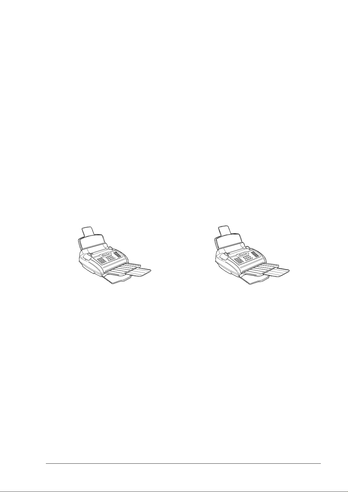
The two models referred to in this manual are desktop facsimile machines with a
bubble ink jet printing system which complies with the ITU-TS G3 standard for document
transmission and reception.
The most suitable factor to distinguish between the two models, similar in appearance, is the possibility of using a monochrome print head only or both monochrome and
colour print heads.
The colour model, once connected to a PC equipped with the LinkFax 8 software
communication module, can be transformed into a multifunctional product able to
perform both printer and scanner functions in addition to the facsimile traditional
features. The colour print head must be used only for printing purposes. All standard
facsimile functions require a monochrome print head. In this manual, the two models
are referred to as follows:
standard model (monochrome) LinkFax model (colour)
1.1 MAIN FEATURES
• Bubble ink jet printing
The facsimile machine prints on plain paper (standard model) or special paper
(LinkFax model) in various formats (A4, Letter, Legal).
• Memory capacity
The facsimile machine has a memory which enables operations such as Onetouch Dialling, Speed Code Dialling, Broadcasting Transmission, Delayed Transmission and Substitute Reception, as well as the storage of parameters, data and
documents. This memory is powered by a backup battery in the event of a power
failure.
• Half tones
In the scanning of documents, a scale of 64 half tones can be used for a higher
XEROX DFC165 & DWC165c Service Manual
1-1
Page 9

quality reproduction of photographs and pictures.
• Automatic document feeder (ADF)
This device enables up to 10 sheets of A4, A5, Letter US or Legal paper, with a
maximum thickness of 0.1 mm/sheet, to be fed in automatically.
• Telephone answering device (TAD)
The model without a built-an TAD can be connected to an external one.
1.2 TECHNICAL SPECIFICATIONS
Physical characteristics
Type
Dimensions (L, D, H)
Weight
Operator console
Display
Keypad
Power supply
Operating range
Average consumption
Desktop transceiver
324 x 325 (+ 1701 + 1182) x 230 (+ 602)mm
6.3 kg
2 lines of 16 characters
- 11 function keys of which 7 are dual function
- 12 dual-function keys for normal dialling
and user name setting
- 10 one-touch dialling keys
- 1 error LED
220-240V, 50/60Hz
11W (in standby); less than 30W (copying)
Communication characteristics
Type of connection
Compatibility
Type of modulation
Transmission speed
Public telephone network (PSTN) or private branch exchange (PBX)
ITU-TS G3 standard
CCITT V29 / V27ter
2400 / 4800 / 7200 / 9600 bps
(1) with the document output tray (2) with extension >>
1-2
XEROX DFC165 & DWC165c Service Manual
Page 10

Type of communication
Half duplex
Coding methods
Transmission time
Scanner
Scanning system
Resolution
Document size
(width x length)
Actual scanning area
Automatic document feeder (ADF)
MH, MR
About 15 s for ITU-TS test sheet n°1 (Slerexe Letter)
at 9600 bps in standard resolution
CCD (Charge Coupled Device)
Vertical: 3.85 (standard) / 7.7 (fine) lines/mm
Horizontal: 8 dots/mm
From 148 x 105 mm (minimum length) to 216 x 2000 mm
(maximum length)
Horizontal: 210 mm
Vertical: within 4 mm of the edge of the document
Capacity: 10 sheets of A4 / Letter US / Legal format
(thickness max 0.1 mm/sheet)
Thickness of sheets: min 0.06 mm, max 0.12 mm
Half tones
Contrast
Printer
Printing method
Printing speed
Automatic sheet feeder
Print resolution
Actual printing area
The facsimile machine can emphasize the contrast of text
areas and reproduce pictures with 64 half tones.
Three levels are handled: dark, normal and light
Bubble ink jet on plain paper (standard model) or special
paper (LinkFax model)
ITU-TS test sheet n°1 (Slerexe Letter) / about 40 s
Capacity: 80 sheets of A4 / Letter US / Legal format
(weight 70-90g/m2)
200 x 100 / 200 dpi
208 x 290 (A4) / 273 (Letter US) / 349 (Legal) mm
Memory
Capacity
XEROX DFC165 & DWC165c Service Manual
512 kbytes (about 360 kbytes as user memory) powered by a backup battery
>>
1-3
Page 11

Dialling
Dialling mode
Dialling on facsimile machine
Redialling
One-touch dialling
Speed code dialling
Delayed transmission
Broadcasting transmission
Other features
Automatic reception
Pulse and tone
The number can be dialled directly on the facsimile machine's
keypad
A number can be redialled in automatic or manual mode
There are 10 one-touch dialling keys
There are 32 memory locations, each of which may be as-
signed a facsimile ID
A document can be sent automatically at a preset time
A document may be sent automatically to several correspond-
ents (max 10).
The facsimile machine can be set to receive a document
automatically
Polling
Reports
Environmental conditions
Temperature
Relative humidity
Polling reception and free polling trasmission features are
available
Various kinds of reports may be printed (transmission, activity,
etc.)
Operating: from 5°C to 35°C
Storage:from 0°C to +45°C
Transport:from -15°C to +45°C
Operating: from 15% to 85 % (without condensation)
Storage: from 15% to 85 % (without condensation)
Transport: from 5% to 95 % (without condensation)
1-4
XEROX DFC165 & DWC165c Service Manual
Page 12
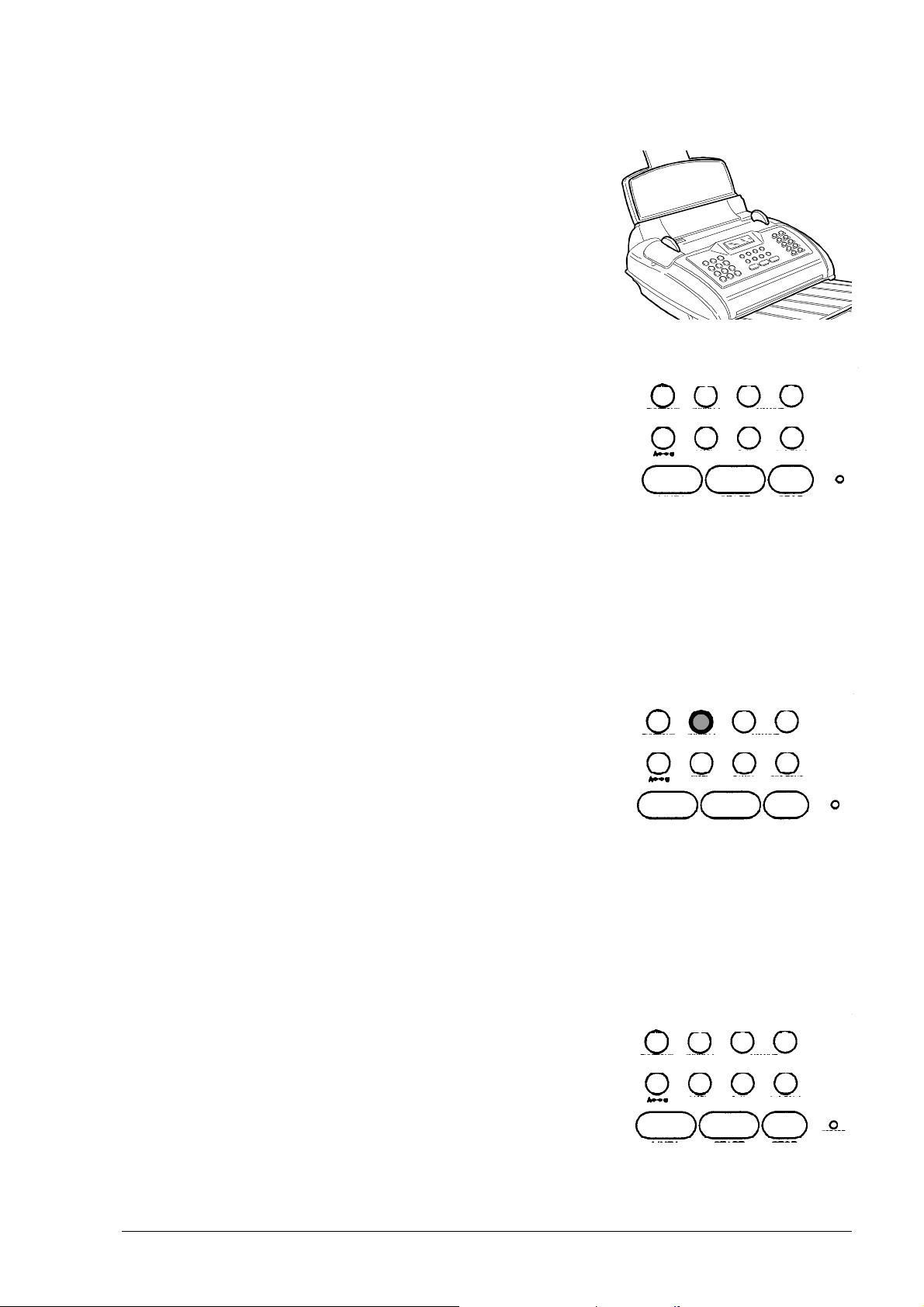
1.3 QUICK REFERENCE GUIDE
1.3.1 Sending a Fax
1. Insert the document into the automatic document
feeder.
2. Press the HOOK key and dial the correspondent's
number on the numeric keypad.
3. Wait for the answering tone from the correspondent's machine and then press START.
1.3.2 Receiving a Fax
S. DIAL
î
HOOK
ê
RX MODE
LAST TX
REDIAL
RESOL.
- VOLUME +
EXT.
PAUSE 2.TONE
í
START
CONTR.
HOLD
ERROR
STOP
1. The facsimile machine is normally set for automatic
reception: the message AUTOMATIC RX is dis-
played.
S. DIAL
2. If you want to receive a fax in manual mode, press
the RX MODE key: the message MANUAL RX will
be displayed.
1.3.3 Using the Facsimile Machine as a Photocopier
1. Insert the document into the automatic document
feeder.
S. DIAL
2. Type on the numeric keypad the number of copies
to start (max. 50 copies)
3. Press the START key.
HOOK
ê
RX MODE
LAST TX
REDIAL
RX MODE
LAST TX
REDIAL
RESOL.
- VOLUME +
EXT.
PAUSE 2.TONE
START
RESOL.
- VOLUME +
EXT.
PAUSE 2.TONE
ê
START
CONTR.
HOLD
STOPHOOK
CONTR.
HOLD
STOP
ERROR
ERROR
XEROX DFC165 & DWC165c Service Manual
n
1-5
.
Page 13
2. GENERAL DESCRIPTION
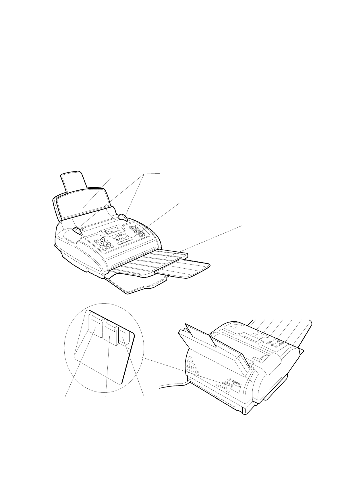
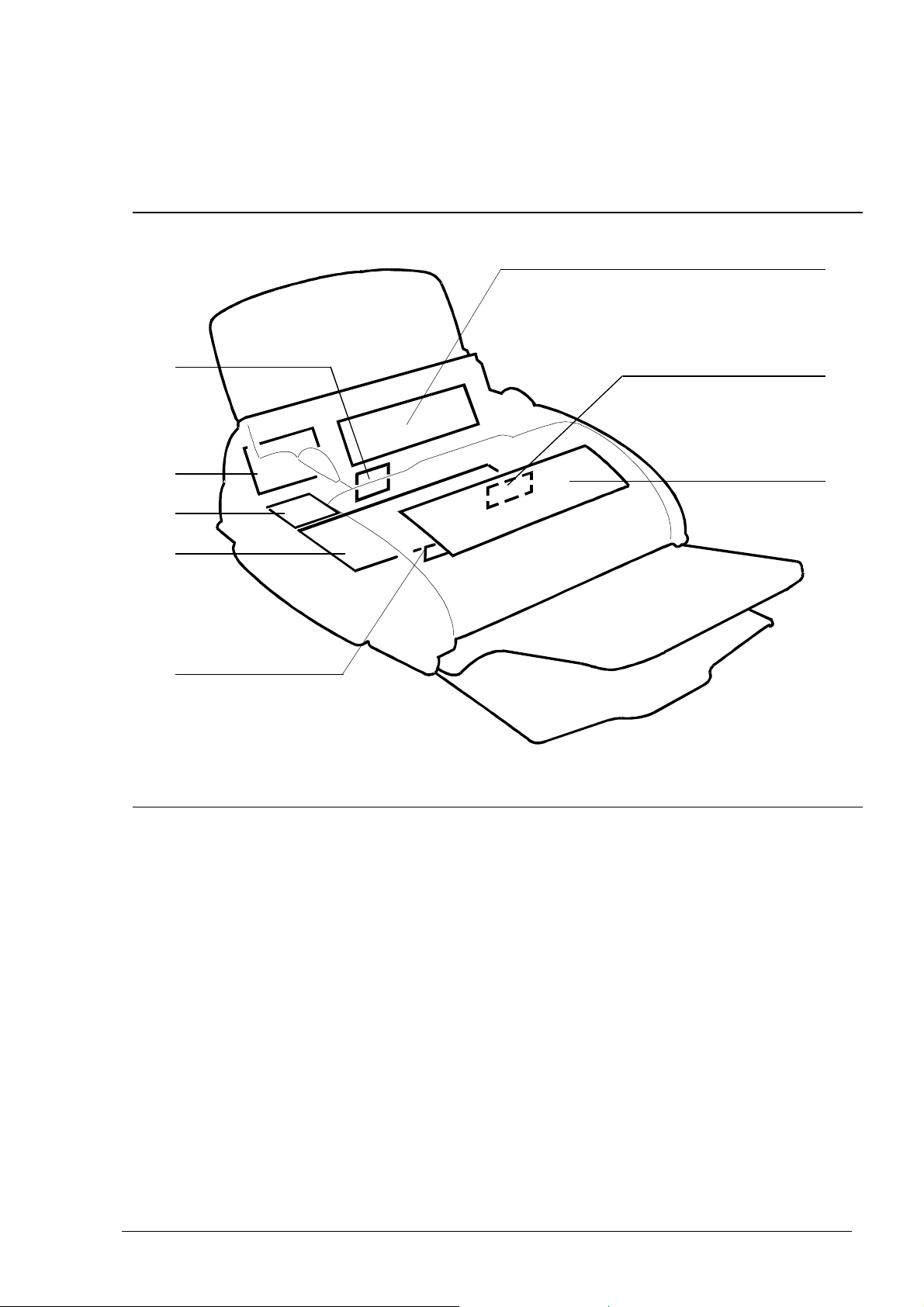
2.1 EXTERNAL PARTS
The figure shows the main external parts, of the facsimile machine.
Automatic sheet feeder
(ASF) cover
Automatic Document
Feeder (ADF) guides
Console
Document
tray
Received and copied
document tray
TAD socket
TEL2
XEROX DFC165 & DWC 165c Service Manual
Telephone
socket
TEL1
Fig. 2-1 External parts of the facsimile machine
Line
socket
LINE
2-1
Page 14
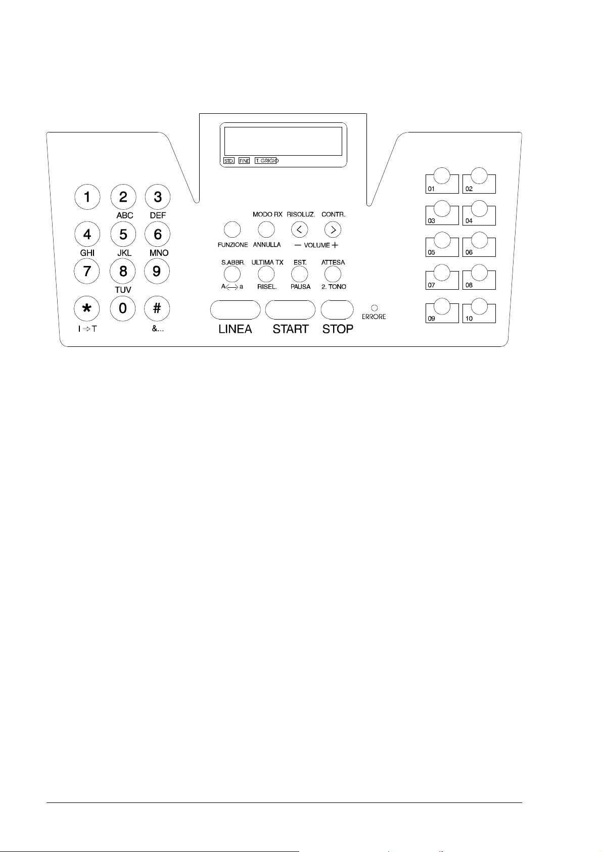
2.1.1 Console
PQRS
WXYZ
Fig. 2-2 Console layout
The console comprises:
• a display consisting of 2 lines of 16 characters each
• a keypad consisting of:
- 11 function keys ( HOOK - START - STOP - S. DIAL - LAST TX - EXT. - HOLD -
FUNCTION - RX MODE - RESOL. - CONTR.) of which 7 are dual function keys
(CLEAR - VOLUME+ - VOLUME- - A↔a - REDIAL - PAUSE - 2.TONE)
- 12 dual-function keys: for normal dialling (0 - 1 - 2 - 3 - 4 - 5 - 6 - 7 - 8 - 9 -
* - #) or user name setting (ABC - DEF - GHI - JKL - MNO - PQRS - TUV
- WXYZ - P→T - &...)
- 10 keys for one-touch dialling
- 1 LED for indicating an ERROR.
2-2 XEROX DFC165 & DWC165c Service Manual
Page 15

2.1.2 Functions of the console keys
Some keys perform different functions according to the current operating mode of the
facsimile machine:
• Stand-by mode with document on the ADF
‚ Stand-by mode without document on the ADF
ƒ Function mode (activated by pressing the FUNCTION key), irrespective of
the presence of a document on the ADF
„ Hook mode (activated by pressing the HOOK key).
Key Mode Functions
•„ Used for dialling numbers.
Number keys ƒ Select alphanumeric characters for inclusion in the mne-
monic ID.
•„ In pulse dialling mode, changes the dialling mode to tone.
In tone dialling mode, emits a tone on line for special network
servces.
« ƒ Scrolls forwards through the special characters and sym-
bols available for the mnemonic ID or selects the + character
for the user's telephone number.
•„ In tone dialling mode, emits a tone on line for special network
services.
# ƒ Scrolls backwards through the special characters and
symbols available for the mnemonic ID.
FUNCTION •‚ Provides access to operator selection menus and
submenus.
RX MODE •‚ Changes the reception mode : automatic, manual, FAX/
TEL, FAX/TAD.
CLEAR •‚ƒ Clears incorrect settings.
RESOL. • Selects the type of resolution.
< ƒ Moves the cursor left during entry of the user's name and
number.
- VOLUME „ Reduces the volume of the speaker.
XEROX DFC165 & DWC 165c Service Manual
>>
2-3
Page 16

Key Mode Functions
CONTR. • Selects the type of contrast.
> ƒ Moves the cursor right during entry of the user's name and
number.
VOLUME + ‚„ Increases the volume of the speaker.
S. DIAL •‚ Enables the setting of a two-digit code for speed dialling.
A↔a ƒ Changes from capitals to small letters (or vice versa)
during entry of the mnemonic ID.
LAST TX •‚ Pressed once, displays the result of the last transmission.
REDIAL •‚ Pressed twice, redials the last number.
EXT. • When the facsimile machine is connected to a private branch
exchange, enables access to the public line .
PAUSE •‚ƒ Inserts a pause in automatic dialling and in speed and one-
touch dial settings.
HOLD • Puts a telephone call on hold.
2. TONE •‚ Sets the second tone in automatic dialling and in speed and
one-touch dial settings.
HOOK •‚ Enables the user to dial the number without lifting the
receiver and to monitor the tones through the speaker.
• Start one-touch dialling the fax number associated with
the key.
Keys 01-10 ‚ Enable the telephone number associated with the key to be
dialled when the START key is pressed.
ƒ Used for programming a one-touch dialling number.
• Switches off the ERROR LED.
Stops copying, sending or receiving a document.
STOP ƒ Sets the facsimile machine in standby mode.
>>
2-4 XEROX DFC165 & DWC165c Service Manual
Page 17

Key Mode Functions
• Starts copying the document on the ADF.
After the number has been dialled, starts sending the
document on the ADF.
START ‚ After a one-touch dial key has been pressed, starts dialling
the programmed telephone number.
After the receiver has been lifted, sets the facsimile machine
in manual reception mode.
ƒ Confirms menus, submenus, parameters and values.
„ Sets the facsimile in manual reception mode.
XEROX DFC165 & DWC 165c Service Manual
2-5
Page 18
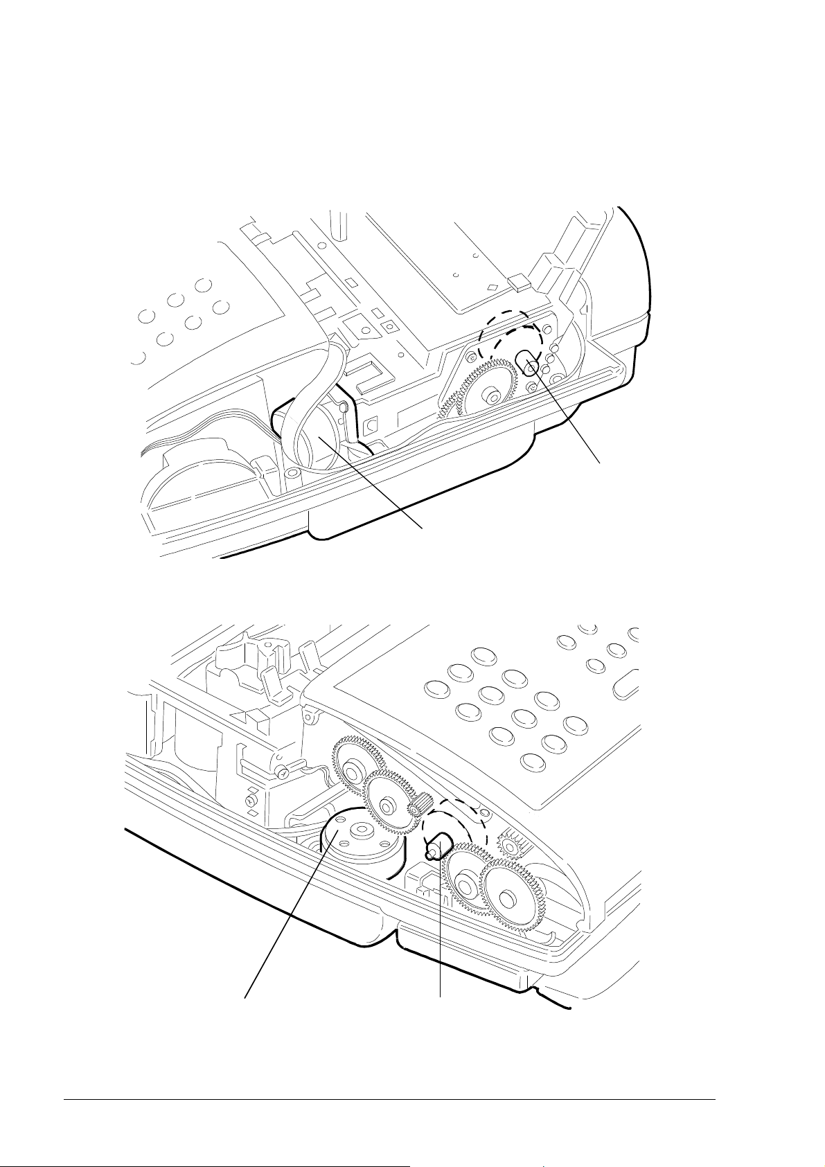
2.2 ELECTROMECHANICAL PARTS
2.2.1 Motors
Rear right-hand side
paper motor
Rear left-hand side
carriage motor
ink drain motor
Fig. 2-3 Locating the motors
2-6 XEROX DFC165 & DWC165c Service Manual
scanner motor
Page 19
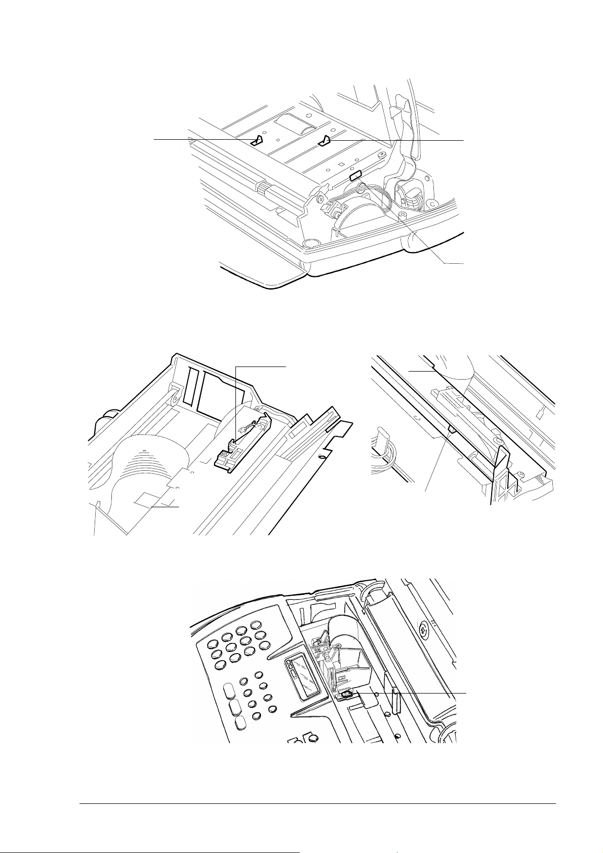
2.2.2 Sensors
document
end sensor
document
sensor
console
sensor
Fig. 2-4 Locating the console sensors
Printer
cover
sensor
paper sensor
(under paper
guide cradle)
Fig. 2-5 Locating the paper and printer sensors
Fig. 2-6 Locating the carriage sensor
paper
edge
sensor
XEROX DFC165 & DWC 165c Service Manual
2-7
Page 20
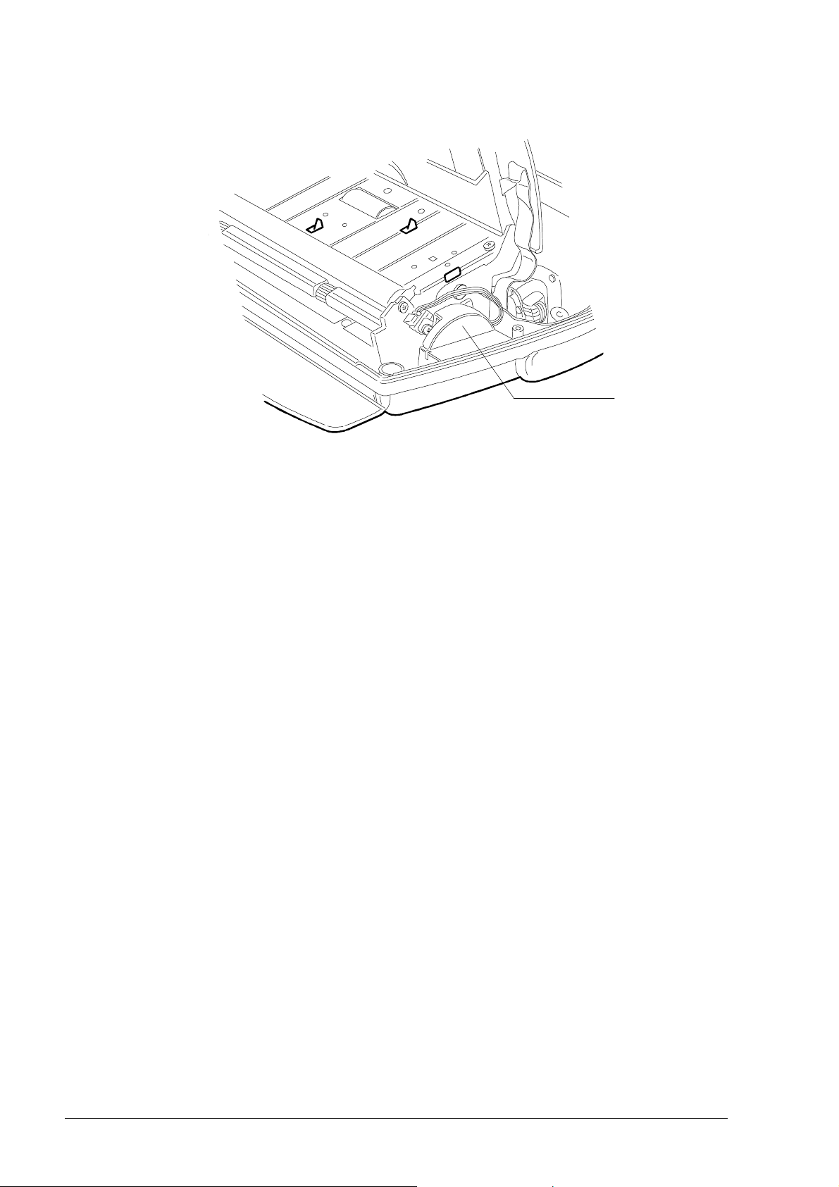
2.2.3 Speaker
speaker
Fig. 2-7 Locating the speaker
2-8 XEROX DFC165 & DWC165c Service Manual
Page 21
2.3 ELECTRONIC PARTS
Figure 2-8 shows the boards assembled on the facsimile machine.
3
4
5
6
7
8
2
1
Fig. 2-8 Locating the boards
1. Console board
2. CCD board
3. Power supply board
4. Print head driver board (in the print carriage)
5. Network control unit (NCU) board
6. Parallel port card (LinkFax model, only)
7. Motherboard
8. LED array for illuminating the documents.
XEROX DFC165 & DWC 165c Service Manual
2-9
Page 22
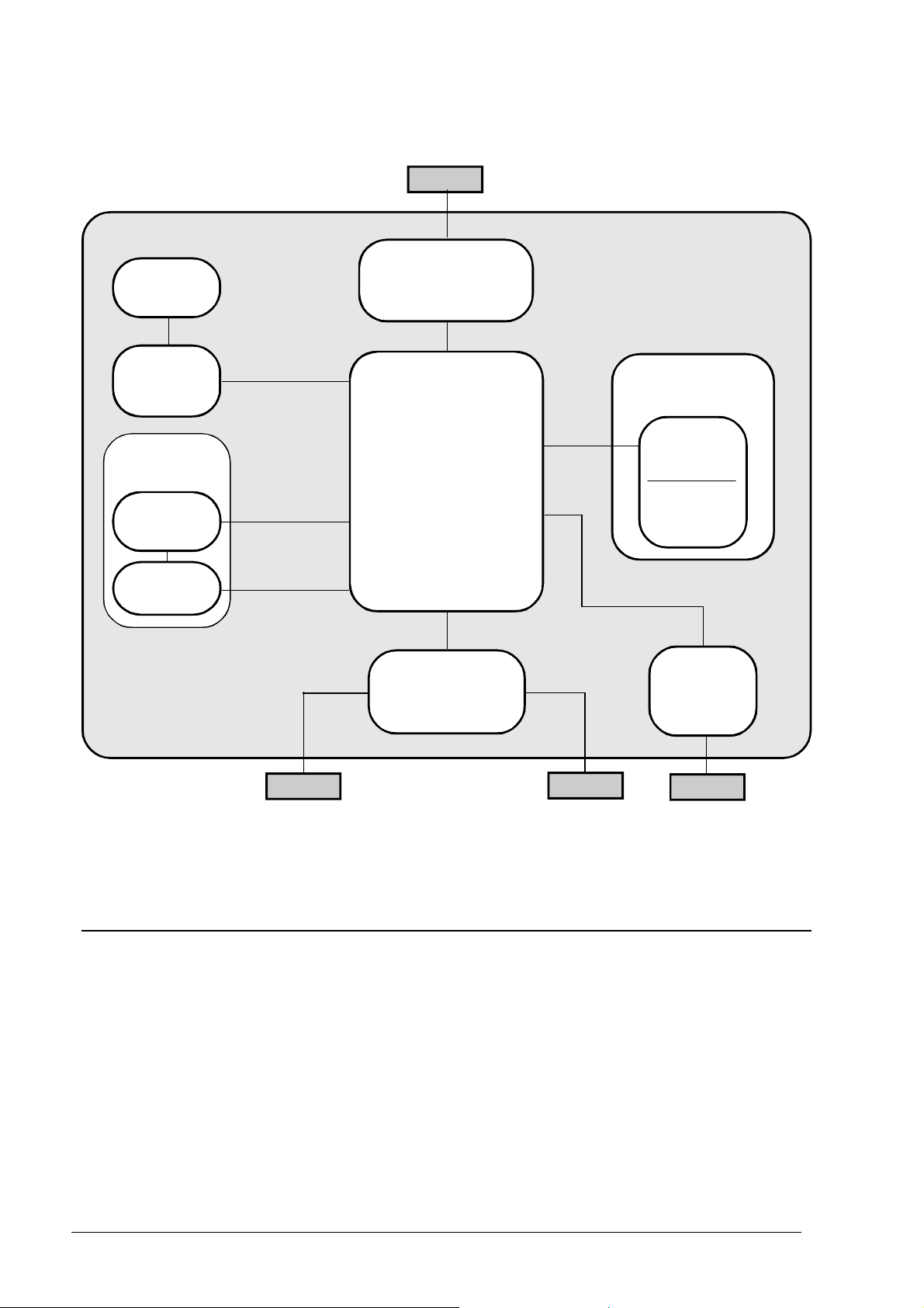
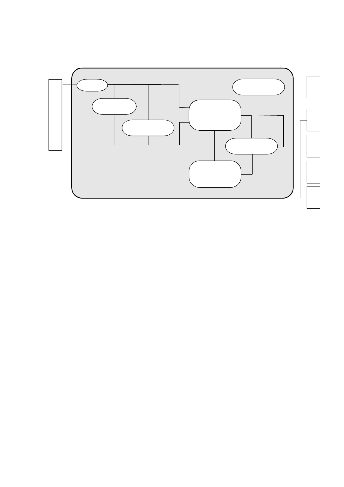
2.3.1 General Block Diagram
Mains voltage
Display
Power supply
board
Console
board
Optical
unit
Scanner
unit
CCD
board
Telephone
network
Motherboard
NCU
board
Telephone
Telephone
orTAD
Print unit
Print
carriage
Driver
board
Parallel
port card
PC
(LinkFax model
only)
Fig. 2-9 General block diagram
The facsimile machine comprises the following main units:
• Motherboard
• Network control unit (NCU) board
• Console board, with the display
• Power supply board
• Parallel port card, for connectiion
to the PC (LinkFax model, only)
2-10 XEROX DFC165 & DWC165c Service Manual
• Optical unit, consisting of the scanner unit and CCD board
• Printer unit, consisting of the print
head driver board (in the carriage)
and the carriage drive mechanism.
Page 23
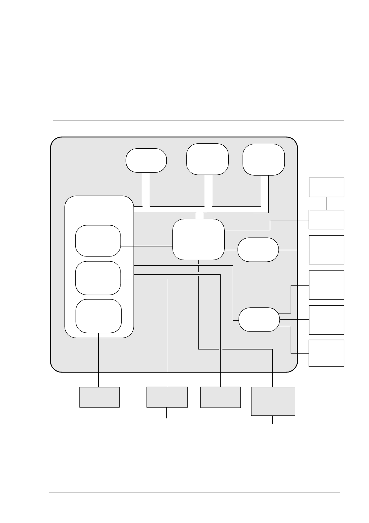
2.3.2 Block Diagram of the Motherboard
The motherboard controls the entire machine by means of a central processing unit
(CPU) which uses special circuits to handle four main functional units: the image
processor (for processing the scanned document), the motors (for activating all the
mechanical parts), the print head (for printing both received and copied documents)
and the modem (for controlling the signals to and from the telephone network).
CPU
I/O channel
controller
Modem
Image
processor
256 kB
EPROM
8 kB
static
memory
Custom
component
ASIC
512 kB
dynamic
memory
Step motor
driver
Step motor
driver
to print
head
to print
head
driver
to carriage
motor
to paper
motor
to scanner
motor
to CCD
board
to NCU
board
Telephone
network
Fig. 2-10 Block diagram of the motherboard
XEROX DFC165 & DWC 165c Service Manual
to console
board
to ink drain
motor
to the
parallel
port card
PC
2-11
Page 24
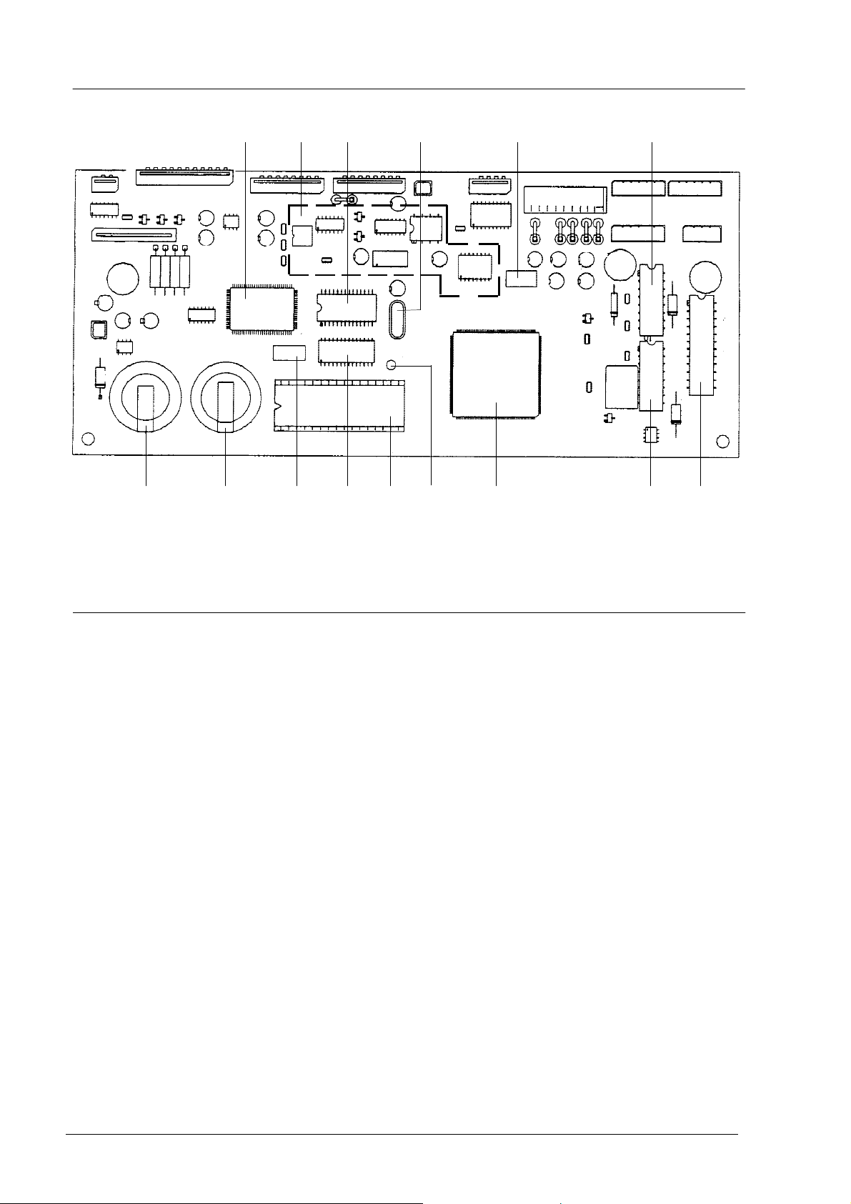
1 2 3 4 5 6
7 8 9 10 11 12 13 146
Fig. 2-11 Locating the motherboard components
1 CUSTOM COMPONENT ASIC
2 MODEM CIRCUITS
3 STATIC RAM (8 x 8 kbytes)
4 QUARTZ CRYSTAL FOR MODEM
CLOCK (20.736 MHz)
5 QUARTZ CRYSTAL FOR SYSTEM
CLOCK (16 MHz)
6 PAPER, SCANNER AND INK DRAIN
MOTOR DRIVERS
7 BACK-UP RECHARGEABLE BATTERY
FOR DYNAMIC RAM (Ni-Cd, 3 volts,
72-hour duration)
8 SYSTEM BATTERY (Lithium, 3
volts, 5-year duration)
9 QUARTZ CRYSTAL FOR ASIC (16
MHz)
10 DYNAMIC RAM (512 kbytes)
11 SYSTEM FIRMWARE EPROM (256
kbytes)
12 QUARTZ CRYSTAL FOR RTC
(32.768 kHz)
13 CPU (WITH BUILT-IN MODEM AND
IMAGE PROCESSOR)
14 CARRIAGE MOTOR DRIVER
2-12 XEROX DFC165 & DWC165c Service Manual
Page 25

The memory block, divided into the following three sections, is an integral part of
the motherboard:
EPROM
Static
RAM
• EPROM (256 Kbytes), this memory contains the system firmware, the default
settings of the software parameters and the messages in the various languages
• STATIC RAM (8 kbytes), this memory contains:
- the current user and service software parameters
- the calibration settings (alignment settings, CCD settings)
- the telephone number list (one-touch dialling numbers, speed code
dialling numbers, broadcasting lists)
- the power failure repor .
• DYNAMIC RAM (512 kbytes), this memory contains:
Dynamic
RAM
- the compression and decompression buffer
- the scanning buffer
- the print buffer
- the transaction memory (activity reports)
- the user memory (documents to send, documents received in the memory).
The data is retained in the dynamic memory even during a power failure by a backup
battery capable of powering the system for 72 hours. The facsimile machine must
be left powered for 24 hours to recharge this battery.
The data is retained in the static memory by the 5-year duration system battery.
XEROX DFC165 & DWC 165c Service Manual
2-13
Page 26
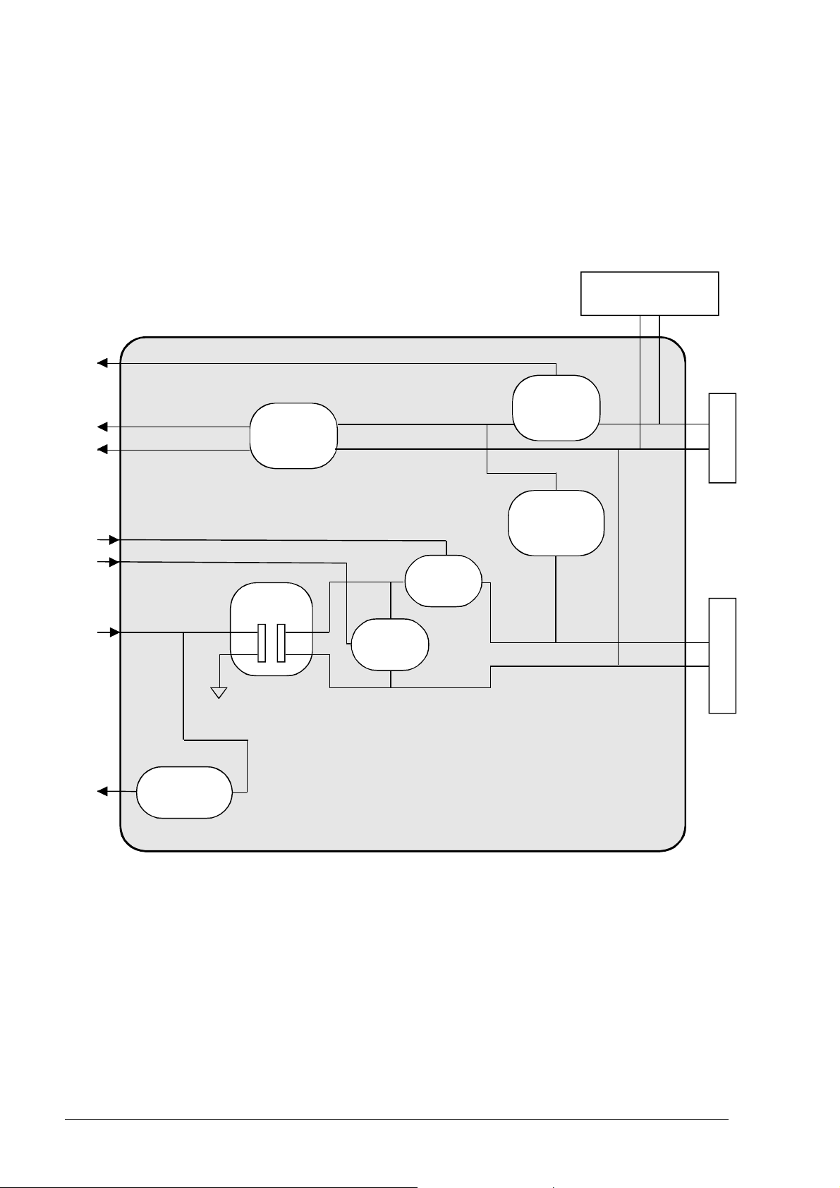
2.3.3 Block Diagram of the Network Control Unit Board
The NCU (Network Control Unit) board acts as the physical interface with the
telephone line. The NCU board is available in several versions, to suit the specific needs
of each country.
The figure shows the block diagram of a generic NCU board.
external TAD
interface
Current
Call
detector
detector
Receiver
detector
relay
Motherboard
TX
Amplifier
RX
Selector
Line
transf.
Selector
relay
relay
Fig. 2-12 Block diagram of a generic NCU board
Telephone line Telephone
2-14 XEROX DFC165 & DWC165c Service Manual
Page 27
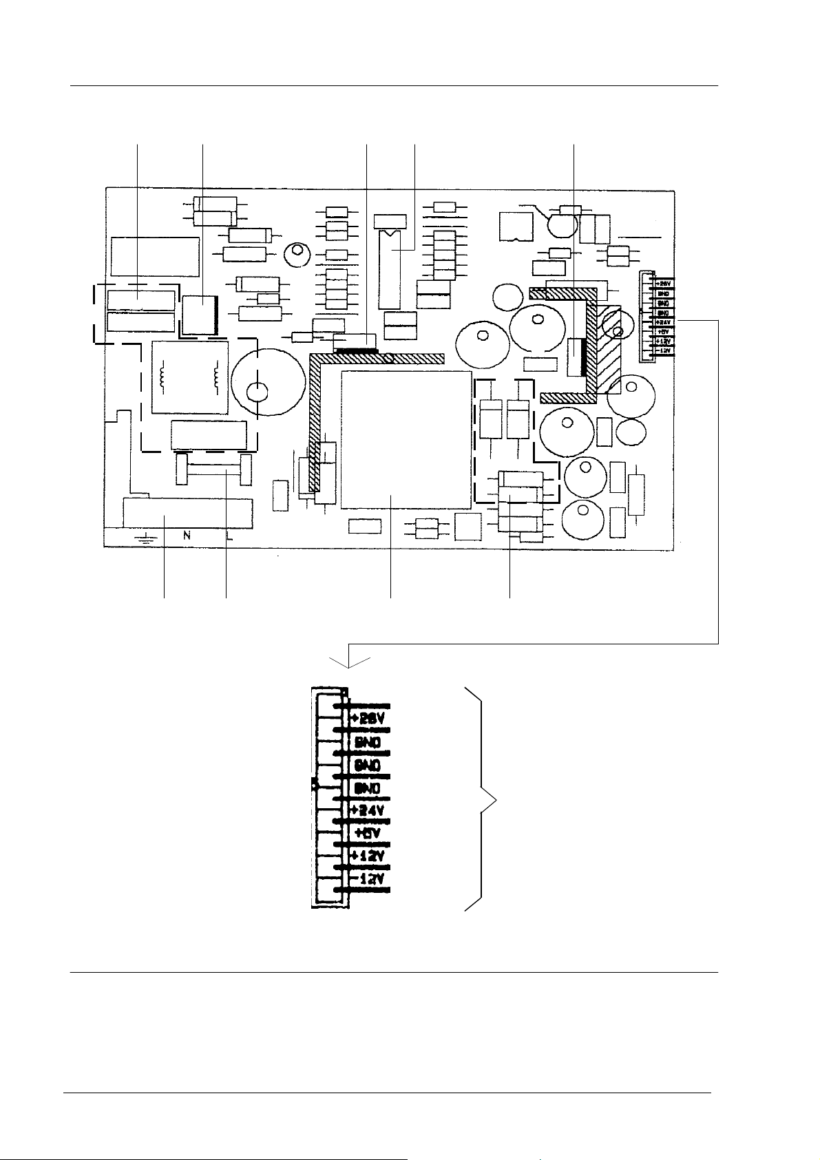
2.3.4 Block Diagram of the Power Supply Board
2 A
Fuse
Mains voltage
Voltage reg.
Mains filter
Switching
transformer
Primary rectifier
Diode rectifier
Switching
controller
MOS
Fig. 2-13 Block diagram of the power supply board
+24 V
+28 V
+5 V
+12 V
-12 V
The power supply board provides a maximum power of 35 Watts and supplies, via
the switching circuit, the following direct voltages:
- +28 VDC (±10%), for the motors, variable according to the load
- +24 VDC (±2%), for the print head
- +12 VDC (±10%), for CCD, NCU and logic circuits
- -12 VDC (+10% -15%), for CCD and logic circuits
- +5 VDC (±5%) for sensors and logic circuits.
XEROX DFC165 & DWC 165c Service Manual
2-15
Page 28
1 2 3 4 5
6 7 8 9
Fig. 2-12a Locating the power supply components
1 Mains filter
PF
+28 V
GND
GND
GND
+24 V
+5 V
+12 V
-12 V
4 Stabilizer
to motherboard
7 Fuse (2 A)
2 Primary rectifier
3 Switching controller MOS
2-16 XEROX DFC165 & DWC165c Service Manual
5 +24 VDC regulator
6 Mains connector
8 Transformer
9 Diode rectifier
Page 29
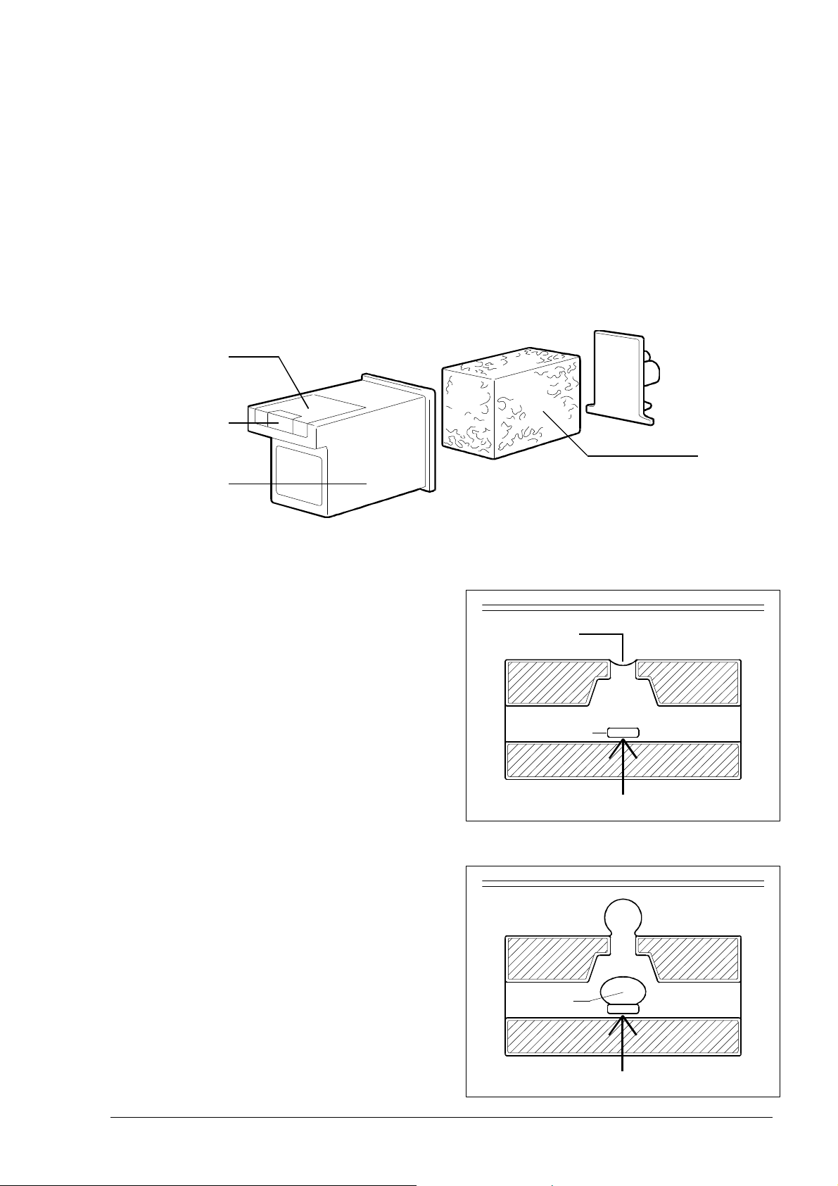
2.3.5 Printer Unit
The facsimile machine has a bubble ink jet system which uses a special head and prints
on plain paper.
The bubble ink jet print head consists of an interchangeable cartridge, which
contains a sponge soaked with liquid ink, which is ejected from 50 nozzles made of a
nickel and gold component, under the control of the signals that reach an electrical
circuit consisting of 50 resistors (Fig. 2-13).
electrical
circuit
nozzles
sponge
cartridge
Fig. 2-13 Composition of the print head
Each nozzle generates a drop of ink
when the corresponding resistor is powered (+24 Volt) for a few microseconds.
The resistor is heated and the ink that is
in direct contact with it evaporates, expanding like a bubble and pressing the rest
of the ink against the nozzle.
nozzle
resistor
bubble
+24V
ink
XEROX DFC165 & DWC 165c Service Manual
+24V
2-17
Page 30
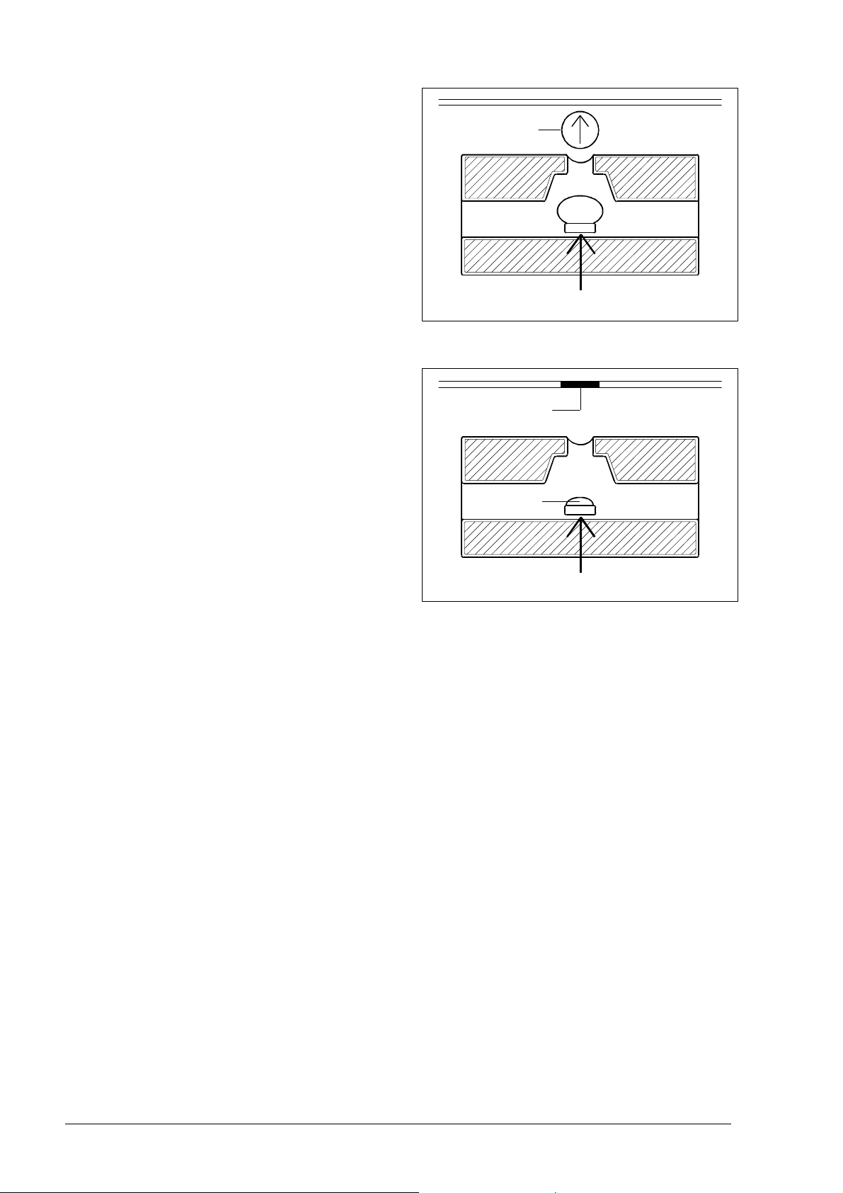
As a result, a drop of ink is ejected from
the nozzle at a speed of 15 metres a second
until it strikes the paper on which it makes
a dot.
drop
15 m/s
+24V
When the resistor is powered off, the
bubble collapses quickly, drawing from
the sponge a quantity of ink equal to the
amount ejected. 800 microseconds after
the ink has been ejected, the nozzle is ready
to eject another drop.
dot
bubble
0V
2-18 XEROX DFC165 & DWC165c Service Manual
n
Page 31

3. INSTALLATION AND INITIALIZATION PROCEDURES
Installation of the facsimile machine consists of three separate phases:
1. PRELIMINARY OPERATIONS, or fitting together the parts supplied in the
packaging and subsequent connection of the facsimile machine and telephone,
if present, to the telephone network
2. INSTALLATION, or setting the parameters indispensable for the facsimile
machine's operation.
3. SETUP, or setting the customization parameters.
3.1 PRELIMINARY OPERATIONS
3.1.1 Unpacking the Facsimile Machine
Having removed the facsimile machine and the other parts from the packaging, check
that the following elements are present:
• the facsimile machine (complete with power cord)
• a packet containing the print head
• the telephone cable (with two international RJ11 connectors)
• an adapter for the telephone cable (only required in some countries)
• the document tray, with a pull-out extension
• the received or copied document tray
• the automatic sheet feeder (ASF), with a pull-out extension
• the User Guide, complete with the Quick Reference Guide.
XEROX DFC165 & DWC165c Service Manual 3-1
Page 32

3.1.2 Connecting to the Telephone Line
WARNING: check that the power cable is plugged into the power outlet,
before connecting the facsimile machine to the telephone line.
To connect the facsimile machine to the telephone line, plug one end of the
telephone cable to the line socket (LINE) on the facsimile machine and the other end
into a wall socket (see Fig. 3-1, a) or using the adapter if necessary (see Fig. 3-1, b).
a)
line socket
(LINE)
b)
Fig. 3-1 Connecting the facsimile machine to the telephone line
To connect a telephone to the telephone network, proceed in either of the following
two ways:
a) if the telephone has a national plug (case a), insert the plug into the adapter
(see Fig. 3-2, a) or specific wall telephone socket (see Fig. 3-2, b)
b) if the telephone has an international connector (case b), remove the precut
tab that covers the telephone socket (TEL1) of the facsimile machine, then
insert the connector directly into the telephone socket (see Fig. 3-3).
Important
As the telephone connection depends on regulations that vary from one country to
another, figures 3-2 and 3-3 show an intentionally generic connection: for a detailed
description of the procedure, see the regulations in force in your own country.
3-2
XEROX DFC165 & DWC165c Service Manual
Page 33

Fig. 3-2 Connecting the telephone (case a)
to telephone
socket on
facsimile
machine
telephone socket
(TEL1)
Fig. 3-3 Connecting the telephone (case b)
XEROX DFC165 & DWC165c Service Manual 3-3
Page 34

3.1.3 Connecting the Power Cord
Plug the power cord into the wall socket.
3.1.4 Installing the Print Head
1) Power on the facsimile machine and wait for the following message to appear:
CHECK PRINT HEAD
WARNING : if the message does not appear in your language, carry out the country
setup procedure described in section 3.2.2 and continue with this
procedure from step 2
2) Open the print head packet and remove the sealed box containing the print head.
3) Open the box and remove the print head, holding it by the grip, then remove the
label covering the nozzles (see Fig. 3-4)
Fig. 3-4 Removing the protective label
WARNING : do not touch the electrical contacts or the print head nozzles
NO
3-4
XEROX DFC165 & DWC165c Service Manual
Page 35

In addition, if the print head has an interchangeable cartridge, do
not separate the cartridge from the print head
NO
4) Tilt the printer cover, then insert the print head in position with the electrical
contacts facing the front of the machine (Fig. 3-5)
Fig. 3-5 Inserting the print head
5) Taking care not to obstruct the hole on the top, insert your index finger in the
recess on the print head and pull it until you hear it clearly click into position
(Fig. 3-6)
Fig. 3-6 Fixing the print head in position
XEROX DFC165 & DWC165c Service Manual 3-5
Page 36

6) Having inserted the print head, close the printer cover
WARNING : if a disposable print head has been inserted, the following
message generally appears:
NEW PRINT HEAD?
1=YES 0=NO
Should this message not appear, press the FUNCTION key three
times, then press the START key to make it appear. Now type 1 and
press the START key.
7) The facsimile machine automatically loads a sheet of paper and starts the nozzle
cleaning and checking procedure, which ends by:
• printing out the following print chart on the automatically loaded sheet (*)
numbered scale
black areas
which contains:
− a numbered scale, for checking the flow of ink and the electrical
circuits controlling the print head nozzles
3-6
− a section of graphics and text, for evaluating print quality
• the following message appears
CHECK PRINTOUT
1=EXIT 0=REPEAT
(*) only if bit 2 of SW09 is set to 1.
XEROX DFC165 & DWC165c Service Manual
Page 37

8) Analyse the print chart as follows:
• Check that there are no gaps in the numbered scale and that there are no
horizontal white lines in the black areas: under these conditions, which
indicate that the print head has been inserted correctly and is in perfect
working order, type 1: the facsimile machine returns to stand-by and is ready
for use
• If there are gaps or white lines, type 0 to repeat the nozzle cleaning proce-
dure: if the new print chart is still unsatisfactory, repeat the procedure again
• If the printing quality is still not up to the required standard after the procedure has been performed three times, proceed as follows until a satisfactory
print chart is obtained:
- Make a copy of a document with the desired type of graphics and text
and assess its quality.
- Change the type of paper (the paper you are using may be too porous)
and repeat the procedure.
- Remove and reinsert the print head.
- Remove the print head and check that there is no foreign body on the
printing nib; if there is, remove it with care, taking care not to touch the
electrical contacts; slide the print carriage to the right, then clean the print
head cleaning pad using a cotton swab soaked in water, taking care not
to leave any fluff (Fig. 3-7);
print head
cleaning pad
Fig. 3-7 Cleaning the print head cleaning pad
reinsert the print head.
XEROX DFC165 & DWC165c Service Manual 3-7
Page 38

- Remove the print head and clean the contacts with a piece of felt, pressing firmly (see Fig. 3-8);
Fig. 3-8 Cleaning the print head contacts
clean the contacts on the print carriage with a soft, dry cloth (see Fig. 3-9);
3-8
contacts
on print
carriage
Fig. 3-9 Cleaning the contacts on the print carriage
reinsert the print head.
- Replace the print head
- Replace the print carriage (see section 7.2.15).
XEROX DFC165 & DWC165c Service Manual
Page 39

3.1.5 Inserting the Output Trays
Place the received or copied document tray on the guide tabs, and the document
output tray between the two slots on the sides (see Figs. 3-10 and 3-11)
guide tabs
Fig. 3-10 Inserting the received or copied document tray
received or copied
document tray
slot
document
tray
slot
Fig. 3-11 Inserting the document tray
XEROX DFC165 & DWC165c Service Manual 3-9
Page 40

3.1.6 Loading Paper
When adding paper to print received and copied documents, the following three
factors must be taken into consideration and must always match for the facsimile
machine to work properly:
- paper size, i.e. the width of the paper used
- ASF tray width, i.e. the distance between the inner sides of the ASF tray
- printing format, i.e. the setting of the FORMAT parameter in the PRINTER
PARAMETERS menu
1) Check that the ASF is set for the paper size you wish to use, i.e. that the distance
between the inner sides coincides with the width of the paper used. If it does
not, remove the cover of the ASF by gripping it at the centre of its lower edge,
position the two inner sides (using a screwdriver to release them at the bottom)
to fit the paper used (Fig. 3-12):
l on the inner guides (1), for A4 format
l on the outer guides (2), for LETTER and LEGAL formats
2 1
left inner side
right inner side
1 2
Fig. 3-12 Preparing the automatic sheet feeder
2) Reassemble the cover and insert the ASF in its housing, then tilt the cover forward
and load the paper of the desired size (max 70 sheets)(Fig. 3-13)
3-10
XEROX DFC165 & DWC165c Service Manual
Page 41

cover
automatic
sheet
feeder
Fig. 3-13 Inserting the ASF and the paper
3) Close the cover of the ASF and set the FORMAT parameter in the PRINTER
PARAMETERS menu to the value that corresponds to the size of the paper and
width of the tray (see section 3.2.1).
4) Make a copy to check that the job has been carried out correctly: if any of the
factors do not coincide, the following message will appear:
PAPER ERROR
PRESS STOP
5) To eliminate the error, proceed as follows:
l switch off the facsimile machine
l remove the ASF and check that the distance between the inner sides corre-
sponds to the width of the paper used
l power on the facsimile machine and check that the FORMAT parameter
corresponds to the previous setting made
l reinsert the ASF.
3.1.7 Feeding special papers manually on the LinkFax model
When you use the LinkFax model as a printer, the following special papers can be
used: Transparency film (with backing), Transparency film with border, Glossy
paper, Coated paper, and Thick paper.
If the paper to be used is not easily fed into the facsimile machine (i.e. it is too thick,
too heavy or too smooth, as when transparency films with border and thick paper
are used), it is necessary to feed it manually (see chapter 10, Using the facsimile
machine as a printer, Printing with LinkFax 8).
XEROX DFC165 & DWC165c Service Manual 3-11
Page 42

3.2 INSTALLING AND SETTING UP THE MACHINE
The procedures used for installing and setting up the machine may be divided into
indispensable procedures (marked by the background ) and procedures that
depend on the characteristics of the telephone exchange or the user's requirements (marked by the background ).
3.2.1 Organization of the Installation and Setup Parameters
The installation and setup parameters are organized into menus and submenus,
shown on the display as follows:
top line
DISPLAY
bottom line
- the top line is used for displaying:
• menu and submenu items, which represent the operating selections available
on the facsimile machine
• parameters, to which a value is to be assigned to make an operating selection
- the bottom line is used for displaying the keys that handle the items indicated
on the top line, that is:
FUNCTION for selecting menu and submenu items, which can be scrolled
cyclically forwards only, i.e. from the first to the last and then
skipping straight back to the first again
START for confirming menu and submenu items, parameters and
values:
• by confirming a menu, you access the corresponding submenu
3-12
• by confirming a submenu, you access the corresponding
parameters
• by confirming a parameter or its value, you access the next
parameter
XEROX DFC165 & DWC165c Service Manual
Page 43

< > for selecting the values of a parameter, scrolling forwards and
backwards through those available on the machine, or for moving
along the characters that make up the parameter value. In the latter
case, the value must then be set using the numeric keypad
STOP for exiting from installation or setup mode.
A schematic diagram of parameter management is provided below:
OPERATING SELECTION PARAMETER SETTING
FUNCTION
MENU
)FUNC
)FUNC
)FUNC
START
SUBMENU
)FUNC
START
PARAMETER
SELECTION
PARAMETERS
STOP
EXIT FROM
MODE
)START
)START
< >
START
SETTING OF
VALUE
VALUES
)>
)>
The figure that follows provides a detailed illustration of the organization of the
installation and setup parameters.
XEROX DFC165 & DWC165c Service Manual 3-13
Page 44

SUBMENU
INSTALLATION
TEL. LINE SET-UP
LANGUAGE
STATION NAME
PHONE NUMBER
DIAGNOSTICS
PRINT INSTALL.
MENU
TX FROM MEMORY
PRINT OUT REPORT
FAX SET-UP
DELAYED TX
POLLING RX
POLLING TX
INSTALLATION
(*) These parameters
are not displayed in
some national versions.
SUBMENU
SERVICE PARAM.
PARAMETERS
TEL. LINE SET-UP
PUBL. LINE (PSTN) (*)
PRIV. LINE (PBX) (*)
PBX DIAL
PSTN DIAL.
EXT. LINE
REMOTE START
RING COUNT (*)
FAX/TEL TIMER
SILENCE LAPSE (*)
LANGUAGE
ITALIAN
ENGLISH
etc.
STATION NAME
TYPE YOUR NAME
PHONE NUMBER (*)
TYPE YOUR NUMBER
DIAGNOSTICS
REMOTE DIAG.
LINE MONITOR
SERVICE PARAM.
TYPE PASSWORD
COUNTRY SET-UP
SERVICE SWITCHES
SYSTEM TEST
PRINT SERV. SW
PRINT PROT. DUMP
PRINT COUNTERS
VARIOUS SETTINGS
PRINTER PARAMET.
CODED SPEED DIAL
PRINT OUT SET-UP
HEAD MAINTENANCE
PARAMETERS
VARIOUS SETTINGS
ECM
FAILED TX REPORT
BROADC. REP.
DELAY LIST
TX SPEED
HEADER
RETRANS.DOC.
CONF. TEL. NUM.
COPY/TX RES.
BUZZER VOL.
PRINTER PARAMET.
SIZE
REDUCTION
SURPLUS
DATE AND TIME
FORMAT: DD/MM/YY
FORMAT: 24H
FAX SET-UP
DATE AND TIME
ONE TOUCH DIAL
ONE TOUCH DIAL
TYPE ONE TOUCH
NUMBER
SPEED
OVERSEAS
NAME
EDIT ANOTHER
CODED SPEED DIAL
TYPE SPEED NO.
NUMBER
SPEED
OVERSEAS
NAME
EDIT ANOTHER
PRINTOUT SET -UP
PRINT SETTINGS
PRINT: ONE TOUCH
PRINT: SPEED DIAL
PRINT: EXIT
HEAD MAINTENANCE
CLEANING
3-14
XEROX DFC165 & DWC165c Service Manual
Page 45

3.2.2 Setting the Country Parameters
This procedure enables you to adapt some specific parameters automatically to the
values preset for a particular country.
Setting
a) The facsimile machine is in stand-by mode
b) Press FUNCTION to access the main menu
c) Select the SERVICE SWITCHES submenu of the IN-
STALLATION menu.
d) Press START
e) Enter the number 1 1 0 0 and press START to enter
"service" mode
Display
AUTOMATIC RX
09-05-95 14:58
FAX SET-UP
FUNC/START/STOP
SERVICE SWITCHES
FUNC/START/STOP
TYPE PASSWORD
z
COUNTRY SETUP
START/STOP/←/→
f) Press START to confirm the COUNTRY SETUP item
g) Select the desired country (for example, U.K.), and then
press START: the values for the selected country are
automatically loaded, then the facsimile machine returns
to stand-by mode.
WARNING: After setting the country parameters it
is possible, whenever necessary, to
reload the default values for the current country, by means of the following
simplified procedure;
- press in rapid sequence STOP # #
- press START.
AMERICA
START/STOP/←/→
U.K.
START/STOP/←/→
AUTOMATIC RX
09-05-95 14:58
COUNTRY SETUP
START/STOP/←/→
AUTOMATIC RX
09-05-95 14:58
XEROX DFC165 & DWC165c Service Manual 3-15
Page 46

3.2.3 Storing the User's Number and Name
Setting
a) The facsimile machine is in stand-by mode
b) Access the main menu and select the STATION NAME
item on the INSTALLATION menu
c) Press START
d) Enter the user's mnemonic ID:
- you can use a maximum of 16 alphanumeric charac-
ters
- select one character at a time using the numeric keys,
as shown below:
key 1, characters: 1
key 2, characters: 2 A B C
key 3, characters: 3 D E F
key 4, characters: 4 G H I
key 5, characters: 5 J K L
key 6, characters: 6 M N O
key 7, characters: 7 P R S
key 8, characters: 8 T U V
key 9, characters: 9 W X Y
key 0, characters: 0 Q Z
key *, characters: symbols (selected "forwards")
key #, characters: symbols (selected "backwards")
Display
AUTOMATIC RX
09-05-95 14:58
STATION NAME
FUNC/START/STOP
TYPE YOUR NAME
z
Example
TYPE YOUR NAME
JOHN
- each key selects the characters cyclically, starting
from the numeric character and displaying each of the
other characters when pressed
- to change a capital letter into a lower case letter, or
vice versa, press the key A↔a after entering it: the new
mode will remain set until the same key is pressed
again.
- confirm the character selected by pressing the > key:
the cursor will move one place to the right
- to correct an error, move the cursor to the character to
be changed using the > and < keys, and select the
desired character.
3-16
XEROX DFC165 & DWC165c Service Manual
Page 47

Setting
- to delete the entire entry, press CLEAR
Display
- having made the entry, press START to access the
PHONE NUMBER item
e) Press START
f) Enter your number:
- you can enter a maximum of 16 characters using the
numeric keys (0 : 9), the * key (to enter the + character)
and the > key (to enter a space)
- to correct or delete, proceed as for the mnemonic ID
- having made the entry, press START
g) Press STOP to return to stand-by mode.
PHONE NUMBER
FUNC/START/STOP
TYPE YOUR NUMBER
z
Example
TYPE YOUR NUMBER
+39 125 524598
DIAGNOSTICS
FUNC/START/STOP
AUTOMATIC RX
09-05-95 14:58
3.2.4 Setting Up the Telephone Line
According to the type of network to which the facsimile machine is connected
(PUBLIC NETWORK or PRIVATE BRANCH EXCHANGE), the following specific
parameters must be set:
- type of dialling (established by the Telephone Service Manager):
· tone (or multifrequency) (PBX/PSTN DIAL: TONE)
· pulse (PBX/PSTN DIAL: PULSE)
- type of access from private line to public line:
· numeric prefix (EXT. LINE: PREFIX)
· earth pulse (EXT. LINE: EARTH)
· flash pulse (EXT. LINE: FLASH).
XEROX DFC165 & DWC165c Service Manual 3-17
Page 48

In addition to these indispensable parameters, the following parameters may also be
set:
- enabling of extension telephone for activating the facsimile machine ( REMOTE
START), by means of a one-digit code (0-9)
- number of rings after which the facsimile machine prepares for automatic
reception (RING COUNT: 01 / 02 / 04 / 08)
- time (in seconds) after which the facsimile machine with the fax/phone feature
enabled switches to fax mode (FAX/TEL TIMER: 15 / 20 / 30 / 40)
- time (in seconds) after which the facsimile machine connected to an external
telephone answering machine switches to fax mode, when there is no incoming
message (SILENCE LAPSE: 3 / 4 / 6 / 8 / 10 / NO).
Setting
a) The facsimile machine is in stand-by mode
b) Access the main menu and select the TEL.LINE SETUP
submenu of the INSTALLATION menu.
c) Press START
d) Set the parameters to the desired values, following the
explanatory flow chart shown below:
TEL.LINE SET UP
PRIV. LINE (PBX) PUBL. LINE (PSTN)
PBX DIAL:PULSE PBX DIAL:TONE
Display
AUTOMATIC RX
09-05-95 14:58
TEL.LINE SETUP
FUNC/START/STOP
PUBL.LINE (PSTN)
START/STOP/←/→
EXT.LINE:PREFIX EXT.LINE EARTH EXT.LINE: FLASH
TYPE PREFIX
PSTN DIAL:PULSE PSTN DIAL:TONE
REMOTE START:ON REMOTE START:OFF
TYPE CODE
RING COUNT: 01 RING COUNT 02 RING COUNTY:04 RING COUNT:08
FAX/TEL/FAX: 15 FAX/TEL TIMER: 20 FAX/TEL TIMER: 30 FAX/TEL TIMER: 40
E LAPSE: 3 SILENCE LAP
3-18
SILENCE LAPSE: 4 SILENCE LAPSE: 6 SILENCE LAPSE 8 SILENCE LAPSE: 10
XEROX DFC165 & DWC165c Service Manual
Page 49

3.2.5 Completing Installation
Installation may be completed by setting the FAX SET-UP to suit the user's needs.
See the User Manual for a description of the procedure to be followed.
3.2.6 Resetting the Fax Machine
Having installed the machine, if it does not work properly in reception and transmission, reset the parameters to restore the default values and repeat the installation
procedure from the start.
Setting
a) The facsimile machine is in stand-by mode
b) Access the main menu and select the SERVICE
SWITCHES submenu of the INSTALLATION menu.
c) Press START
d) Enter the number 1 1 0 0 and press START to enter
"service" mode
e) Select the SYSTEM TEST item and press START
Display
AUTOMATIC RX
09-05-95 14:58
SERVICE SWITCHES
FUNC/START/STOP
TYPE PASSWORD
z
COUNTRY SETUP
START/STOP/←/→
SYSTEM TEST
START/STOP/←/→
f) Select LOAD DEFAULT and press START twice: the
default values for U.K./SOUTH AFRICA are loaded
LOAD DEFAULT
START/STOP/←/→
automatically in place of those set previously
g) Press STOP to return to stand-by mode.
AUTOMATIC RX
09-05-95 14:58
WARNING: having installed the machine successfully, never repeat the
reset procedure or you will have to reset all personal data set by
the user.
XEROX DFC165 & DWC165c Service Manual 3-19
n
.
Page 50

4. SERVICE SWITCHES
The term service switches is intended to mean parameters that cannot be
accessed by the user and that can only be accessed by service technicians with
the facsimile machine in "service" mode (see section 3.2.2).
These parameters are given default values which depend on the country specifications made by the telephone network manager. As a result, the technician should only
change these values in order to correct the functioning of the machine or to adapt it to
particular local features.
Before changing any of the service switch settings, it is advisable to print them, as
described below:
Setting
Display
a) The facsimile machine is in standby mode
b) Access the main menu and select the SERVICE
SWITCHES submenu of the INSTALLATION menu
c) Press START
d) Enter the number 1 1 0 0 and press START to enter
"service mode"
e) Select the PRINT SERV. SW option
f) Press the START key: the current default values will be
printed (see fig. 4-1)
AUTOMATIC RX
09-05-95 14:58
SERVICE SWITCHES
FUNC/START/STOP
TYPE PASSWORD
z
COUNTRY SETUP
START/STOP/←/→
PRINT SERV. SW
START/STOP/←/→
PRINTING...
STOP
g) Press STOP to return to standby mode.
XEROX DFC165 & DWC165c Service Manual 4-1
AUTOMATIC RX
09-05-95 14:58
Page 51

Fig. 4-1 Example of a printout of the service switch settings
Two types of service switches are available in the SERVICE SWITCHES menu:
- SW01 - SW11: these switches consist of 8 bits and can
be programmed either individually or in group
SERVICE SWITCHES
SW01 01010101
bit no. 76543210
- SWA - SWR: these switches consist of a value ranging
from 1 to 3 digits
SERVICE SWITCHES
SWR 120
Warning: 1) Whenever no value is printed in correspondence with a service
switch SWA-SWR, this means that the value is 0 (zero).
2) Some of the service switches can be set by the user; in these cases,
the user setting takes priority over the service setting. The
parameters concerned are:
User parameter Software parameter
RING COUNT SWB
FAX/TEL TIMER SWM
SILENCE LAPSE SWO
4-2
XEROX DFC165 & DWC165c Service Manual
Page 52

4.1 SERVICE SWITCH TABLES
The tables that follow describe the functions carried out by the bits and combinations
of bits for each service switch. In order to correctly interpret some of the functions
required, a knowledge of the communication protocol is required. The default values
may undergo some modifications due to both homologation and user's peculiarities. For
this reason, you are recommended to print out the service switches of the facsimile
machine to be serviced, always before modifying them.
Switch SW01
bit Function set to 1 set to 0
7 Error code generated YES NO
on failed reception
Next page sent from the ADF
or resent from memory
6 despite bad reception signal YES NO
(RTN) from the receiver
Multifrequency bit 5 4 = 0 0, -11 / -9
5 output level bit 5 4 = 0 1, -8 / -6
4 (dBm) bit 5 4 = 1 0, -12 / -10
bit 5 4 = 1 1, -10 / -8
Cable equalizer bit 3 2 = 0 0, 0 km (0 dB)
3 in reception bit 3 2 = 0 1, 1.8 km (4 dB)
2 (radius of cable = 0.4 mm) bit 3 2 = 1 0, 3.6 km (8 dB)
bit 3 2 = 1 1, 5.6 km (12 dB)
Cable equalizer bit 1 0 = 0 0, 0 km (0 dB)
1 in transmission bit 1 0 = 0 1, 1.8 km (4 dB)
0 (radius of cable = 0.4 mm) bit 1 0 = 1 0, 3.6 km (8 dB)
bit 1 0 = 1 1, 5.6 km (12 dB)
XEROX DFC165 & DWC165c Service Manual
4-3
Page 53

Switch SW02
bit Function set to 1 set to 0
7 Answer to second
6 Tone duration / pause bit 6 5 4 = 0 0 0, 70 / 70
5 in tone dialling bit 6 5 4 = 0 0 1, 70 / 140
4 (ms / ms) bit 6 5 4 = 0 1 0, 87 / 87
3 Disable non standard YES NO
signal from the receiver YES NO
(anti-echo device)
bit 6 5 4 = 0 1 1, 120 / 120
bit 6 5 4 = 1 0 0, 200 / 200
features (NSF)
2 Reception 9600-2400 4800-2400
start speed (V.29,V.27ter)(V.27ter only)
bit 1 0 = 0 0, 9600 bps
1 Transmission bit 1 0 = 0 1, 7200 bps
0 start speed bit 1 0 = 1 0, 4800 bps
bit 1 0 = 1 1, 2400 bps
4-4
XEROX DFC165 & DWC165c Service Manual
Page 54

Switch SW03
bit Function set to 1 set to 0
7 Page loss when 12 mm 8 mm
Automatic transmission in
6 HOOK mode without pressing YES NO
START at the end of dialling
5 emitted by the receiver NO YES
SURPLUS = AUTO
Transmission of the tone
during reception (CED)
4 Anti-echo protect tone YES NO
in transmission
3 Reception sensitivity -47 dBm -43 dBm
bit 2 1 = 0 0, 35 s (*)
2 Wait time for signal from bit 2 1 = 0 1, 60 s (*)
1 receiver during transmission bit 2 1 = 1 0, 90 s (*)
bit 2 1 = 1 1, 130 s (*)
Frequency of the tone
0 emitted by the receiver 1100 Hz 2100 Hz
during reception (CED)
(*) In some countries these bits are set to a single specific value.
XEROX DFC165 & DWC165c Service Manual
4-5
Page 55

Switch SW04
bit Function set to 1 set to 0
7 Reception channel bit 7 6 = 0 1, average
6 evaluation criteria bit 7 6 = 1 0, moderate
5 Pause between digits 800 ms 900 ms
4 Dial pulses bit 4 3 = 0 0, N
3 (N = digits dialled) bit 4 3 = 0 1, N + 1
bit 7 6 = 0 0, strict
bit 7 6 = 1 1, loose
in pulse dialling
bit 4 3 = 1 0, 10 - N
2 Pulse dialling frequency 20 p/s (*) 10 p/s
1 Report printing inhibited always (**)
0 PBX dialling tone YES NO
detection
(*) only valid if the value of switch SWP is halved.
(**) as programmed via TX REPORT user parameter.
4-6
XEROX DFC165 & DWC165c Service Manual
Page 56

Switch SW05
bit Function set to 1 set to 0
7 Earth pulse duration 100 ms 300 ms
6 Flash pulse duration 110 ms 270 ms
5 Pause time bit 5 4 = 0 1, 3 s
4 bit 5 4 = 1 0, 4 s
3 PAUSE key enabling NO YES
bit 5 4 = 0 0, 2 s
bit 5 4 = 1 1, 5 s
2 Limit to the number of unlimited for 11 s
pauses that may be inserted number max
bit 1 0 = 0 0, 1 s
1 Predialling pause bit 1 0 = 0 1, 2 s
0 (*) bit 1 0 = 1 0, 3 s
bit 1 0 = 1 1, 4 s
(*) only valid if dial tone detection is not enabled (SW06, bit 2 = 0).
XEROX DFC165 & DWC165c Service Manual
4-7
Page 57

Switch SW06
bit Function set to 1 set to 0
7 Dialling tone bit 7 6 = 0 1, 360 / 520 Hz
6 frequency range bit 7 6 = 1 0, 300 / 640 Hz
5 bit 5 4 3 = 0 0 1, 800 ms
4 Dialling tone bit 5 4 3 = 0 1 0, 900 ms
3 detection time bit 5 4 3 = 0 1 1, 1200 ms
bit 7 6 = 0 0, 320 / 570 Hz
bit 7 6 = 1 1, 300 / 640 Hz
bit 5 4 3 = 0 0 0, 400 ms
bit 5 4 3 = 1 0 0, 1800 ms
bit 5 4 3 = 1 0 1, 2000 ms
2 PSTN dialling tone YES NO
detection
Shortcircuit
1 between digits YES NO
in pulse dialling
Shortcircuit time
0 on relay, before and after 260 / 70 ms 86 / 48 ms
dialling pulse
4-8
XEROX DFC165 & DWC165c Service Manual
Page 58

Switch SW07
bit Function set to 1 set to 0
7 detected after YES NO
Exchange tones detected
6 during preliminary YES NO
5 Rapid preamble recognition YES NO
during the handshake phase
Busy tone
dialling
phase of reception
4 Minimum memory space 128 kbytes 17 kbytes
reserved to receiving
3 Report always printed YES NO
on failed transmission
2 Busy tone seek time 20 s standard
after dialling (*)
1 Frequency range of 1120: 1160 Hz as for the 1st
second dialling tone Belgian type dialling tone
0 Dialling tone 40 s 10 s
wait time
(*) i.e., as established by the couple of bits 1 and 2 of switch SW03.
XEROX DFC165 & DWC165c Service Manual
4-9
Page 59

Switch SW08
bit Function set to 1 set to 0
7 Full line monitoring YES NO
6 Transmission retries limited YES NO
within a fixed time range (*)
4 detection bit 5 4 = 0 1, -30 dBm
5 threshold bit 5 4 = 1 0, -26 dBm
3 Line feed (*) 1/300" 1/150"
Dialling tone bit 5 4 = 0 0, -40 dBm
bit 5 4 = 1 1, -35 dBm
2 Exit from HOOK mode after 1 h after 1 min
1 Busy tone detected YES NO
before dialling
0 Busy tone sequence 4 sequences 2 sequences
(*) LinkFax model, only
4-10
XEROX DFC165 & DWC165c Service Manual
Page 60

Switch SW09
bit Function set to 1 set to 0
7 Switching off manual automatic
5 reception/transmission bit 6 5 = 0 1, 16 min
6 time for one page bit 6 5 = 1 0, 32 min
4 Size of data block 64 bytes 256 bytes
ERROR LED after 1 min
Maximum bit 6 5 = 0 0, 8 min
bit 6 5 = 1 1, unlimited
packets in ECM (*)
3 Compression method MR & MH MH
2 Print chart enabled YES NO
1 Frequency and sequence of Type B Type A
answer tone in FAX/TEL mode (**) (***)
0 Extended error codes YES NO
(*) only to be used on lines with interference
(**) Frequency: 425 Hz
Sequence: 1 s 4 s
(***) Frequency: 700 Hz
Sequence: 0.1 s 0.1 s 0.1 s 0.1 s 0.1 s 2 s
XEROX DFC165 & DWC165c Service Manual
4-11
Page 61

Switch SW10 (to enable / disable user-level functions)
bit Function set to 1 set to 0
Change in dialling mode
7 by pressing the YES NO
¬ key disabled
6 MMR compression method (*) YES NO
5 Enable remote diagnostics YES NO
4 Set number of rings YES NO
3 Enable pulse mode YES NO
during dialling
2 Set silence time detection YES NO
1 FAX/TEL switch YES NO
0 Set call time YES NO
in FAX/TEL mode
(*) LinkFax model, only
4-12
XEROX DFC165 & DWC165c Service Manual
Page 62

Switch SW11 (to enable / disable user-level functions)
bit Function set to 1 set to 0
7 Enable FAX/TAD NO YES
6 Not used
5 Reserved
4 Protection for YES NO
telephone credit card (*)
3 How the console key always in the selected
names are displayed in English language
2 Linking between fixed to 1
letters and numeric keys (never set to 0)
1 Disable "second tone" NO YES
function of HOLD - 2.TONE key
0 Enable entry of YES NO
sender's number
(*) In order to prevent the secret card code from being either
displayed or printed, only the last 10 digits of the telephone
number are displayed or printed.
XEROX DFC165 & DWC165c Service Manual
4-13
Page 63

Switch SWA
Switch SWB
Switch SWC
Format Function
1 digit Time before answering
(0 : 9) (in seconds)
Format Function
2 digits Number of rings before answering
(01 : 10)
Switch SWD
Switch SWE
Format Function
max 3 digits First ring detection time (in tens of ms)
(001 : 255)
Format Function
max 3 digits Second ring detection time
(001 : 255) (in tens of ms)
Format Function
4-14
max 3 digits Ring reset time (in hundreds of ms)
(001 : 255)
XEROX DFC165 & DWC165c Service Manual
Page 64

Switch SWF
Switch SWG
Format Function
Maximum percentage of
max 2 digits incorrect lines on a page
(00 : 15) without an error message
(00 = function disabled)
Format Function
Maximum number of
max 2 digits incorrect lines on a page
(00 : 15) without an error message
(00 = function disabled)
Switch SWH
(*) 03 : 15 for Italy.
Switch SWI
Switch SWJ
Format Function
max 2 digits Transmission level code
(00 : 15) (*) (in dBm)
Format Function
max 3 digits Minimum ring duration
(010 : 100) (in ms)
Format Function
max 3 digits Maximum ring duration
(010 : 100) (in ms)
XEROX DFC165 & DWC165c Service Manual
4-15
Page 65

Switch SWK
Switch SWL
Format Function
max 2 digits Number rings before answering
(00 : 99) in manual reception mode
(00 = no answer in manual RX)
Format Function
max 2 digits Wait time of the tone emitted by the
(01 : 99) sender before alarm to the operator
in FAX/TEL mode (in seconds)
Switch SWM
Switch SWN
Format Function
max 2 digits Alarm duration
(01 : 99) in FAX/TEL mode (in seconds)
Format Function
max 2 digits Time between two calls while
(01 : 99) broadcasting (in seconds)
Switch SWO
4-16
Format Function
max 2 digits Silence recognition time in
(01 : 59) FAX/TAD mode (in seconds)
XEROX DFC165 & DWC165c Service Manual
Page 66

Switch SWP
(*) with a pulse dialling frequency of 20 p/s, halve the value used with
the 10 p/s frequency.
Switch SWQ
Format Function
max 2 digits Break time
(50 : 80) in pulse dialling (in ms) (*)
Format Function
max 2 digits Number of redials
(00 : 99)
Switch SWR
Format Function
max 3 digits Time between redials (in seconds)
(000 : 999) (000 = no redials)
XEROX DFC165 & DWC165c Service Manual
n
4-17
.
Page 67

5. DIAGNOSTICS
5.1 SELF-DIAGNOSTICS
The facsimile machine automatically runs a diagnostic program (SELF-DIAGNOSTIC TEST) the first time it is powered on and on reactivation after a power failure
or disconnection from the mains:
- if the self-diagnostic test is passed, the facsimile machine enters standby mode
- if the self-diagnostic test is failed as a result of a correctable error, the facsimile
machine displays an error code on the display.
If this occurs, you must always replace the motherboard, unless a keyboard
error occurs (in this case you must replace the console board or the flat cable that
connects it to the motherboard).
The self-diagnostic routine tests the following components:
• EPROM
• keyboard
• printer.
The self-diagnostic test stops at the first test in which a fault is detected.
XEROX DFC165 & DWC165c Service Manual 5-1
Page 68

5.1.1 Description of the Self-Diagnostic Program
Diagnostic step Error message
1) The facsimile machine is powered on: the error LED lights up.
2) The EPROM is tested.
3) The keyboard RAM is tested.
4) The keyboard EPROM is tested.
5) The display is tested.
6) Communication between the keyboard and motherboard is tested.
7) Printer startup: check that the
print carriage is reset.
8) The paper edge sensor is tested.
SYSTEM ERROR 93
SYSTEM ERROR 06
SYSTEM ERROR 07
SYSTEM ERROR 08
SYSTEM ERROR 09
SYSTEM ERROR 03
SYSTEM ERROR 04
(*)
9) The position of the print carriage
is tested.
10)The facsimile machine enters
stand-by mode: the error LED
SYSTEM ERROR 05
AUTOMATIC RX
09-05-95 14:58
gets off.
(*)This error also occurs if the print head is mounted the wrong way round, that is, with
the contacts facing the rear; consequently, start by checking that the print head is
positioned correctly.
5-2
XEROX DFC165 & DWC165c Service Manual
Page 69

5.2 ERROR CODES
The error codes are printed on the journals (see section 5.3).
The format of these error codes, excluding those referring to the self-diagnostic test
(described in section 5.1.1), may be:
- one group of two digits (xx)
- two groups of two digits separated by a dot ( xx.xx); this extended format:
• indicates the category to which the error belongs, by means of the first group,:
01 Document incorrectly positioned
02 Unable to connect
03 No answer from correspondent
04 Failed transmission
05 Incomplete transmission
07 Document too long
08 Document jam
10 Failed or incomplete reception
11 No reception due to memory full
13 Failed polling reception
16 Power failure
• provides more detailed information about the error, by means of the second
group, and may be requested by the technician with the machine in "service"
mode (see section 3.2.2), by setting bit 0 of switch SW09 to 1 (see section 4.1).
In the tables that follow, the error codes are indicated in their extended format and
in ascending numeric order.
For an explanation of the meaning of the protocol signal codes that appear in the
description of the causes of errors, see the next section (5.2.1).
Important: to ensure correct identification of the cause of the error, we recom-
mend you always print the communication protocol (PROTOCOL
DUMP, see section 5.2.3).
XEROX DFC165 & DWC165c Service Manual 5-3
Page 70

5.2.1 Meaning of Protocol Signal Codes
Code Name Type of signal
CRP Command Repeat GENERIC
CED Called (Station Identification)
CIG Calling (Subscriber Identification)
CSI Called asubscriber Identification
DIS Digital Identification Signal
NSC Non-Standard Command INITIAL
IDENTIFICATION
NSF Non-Standard Facilities
NSS Non-Standard Set-up
TCF Training Check Frame
TSI Transmitting Subscriber Identification
DTC Digital Transmit Command POLLING
COMMANDS
DCS Digital Command Signal TRANSMISSION
COMMANDS
CFR Confirmation To Receive PRE-MESSAGE
ANSWERS
FTT Failure To Train
CTC Continue To Correct
EOM End-of-Message
EOP End-of-Procedure
EOR End-of-Retransmission POST-MESSAGE COMMANDS
MPS Multipage Signal
PPS Partial Page signal
5-4
XEROX DFC165 & DWC165c Service Manual
>>
Page 71

PRI Procedure Interrupt
RR Receive Ready
CTR Response to CTC
ERR Response to EOR
MCF Message Confirmation
PIN Procedure Interrupt Negative
PIP Procedure Interrupt Positive POST-MESSAGE ANSWERS
PPR Partial Page Request
RNR Receive Not ready
RTN Retrain Negative
RTP Retrain Positive
DCN Disconnect DISCONNECTION
XEROX DFC165 & DWC165c Service Manual 5-5
Page 72

5.2.2 Meaning of Error Codes
Code Cause of Error Action
02.00 Unable to connect None
03.00 No answer from correspondent Call again
04.00 No connection due to Call again
disconnected correspondent
(DCN received)
04.01 No connection due to incompatible Call again
correspondent
(during handshake phase)
04.02 No connection due to incompatible Call again
correspondent
04.03 No connection due to incompatible Call again
correspondent
(incompatible confirmation signal)
04.04 No connection due to incompatible Call again
correspondent
(DCN instead of confirmation signal)
04.05 Line error as no further speed Call again
fall-back is possible
04.06 No connection due to problems Call again
on receiver's side (no answer)
04.07 No answer during Call again
post-message phase
04.08 Answer not allowed during Call again
post-message phase
04.09 No development of protocol Call again
04.10 Answer not allowed during Call again
post-message phase in ECM
5-6
XEROX DFC165 & DWC165c Service Manual
>>
Page 73

Code Cause of Error Action
04.11 No answer during Call again
post-message phase in ECM
04.12 Insufficient memory Call again
on receiver's side
05.00 Transmission incomplete Call again
07.00 Document too long Call again
08.00 Document jam Remove document
09.00 STOP pressed during TX or RX None
10.00 Text coding error None
at start of message
10.01 No connection due to None
incompatible correspondent
10.02 No reception due to no answer None
from correspondent during
handshake, or at the end of the block, or at
the end of a page with change in resolution
10.03 Line error due to incompatible None
speed
10.04 No commands received Call again
from correspondent
10.05 Text coding error None
(5 seconds without data)
10.06 No signal during Call again
reception of the message
10.07 No commands received Call again
from correspondent at start of message
10.08 No document present on None
polling request
>>
XEROX DFC165 & DWC165c Service Manual 5-7
Page 74

Code Cause of Error Action
10.09 Page received incorrectly Call again
(RTN transmitted)
10.10 No commands received from Call again
correspondent at start of message
(in ECM)
10.11 Page received incorrectly in ECM Call again
(ERR sent)
10.12 Busy tone recognized Call again
during handshake
10.13 Text coding error during None
reception of the message
11.00 Riception incomplete due to Clear unwanted documents
user memory full from the memory
11.10 Riception incomplete due to Clear unwanted documents
user memory full in ECM from the memory
13.00 Failed polling reception Call again
16.00 Power failure None
5-8
XEROX DFC165 & DWC165c Service Manual
Page 75

5.2.3 Printing the Communication Protocol
Setting Display
1) The facsimile machine is in standby mode.
b)
Enter "
service" mode and select PRINT PROT. DUMP
c) Make sure that there is paper in the ASFand then press
START: the data shown in fig. 5-1 will be printed and then
the facsimile machine will return to standby mode.
AUTOMATIC RX
09-05-95 14:58
PRINT PROT DUMP
START/STOP/←/→
PRINT PROT.DUMP
START/STOP
Fig. 5-1
The protocol status is presented, session by session, by means of the following fields:
TIMER Indicates the times, in minutes : seconds, at which the signals were
exchanged during the session
LOCAL Indicates the signals, represented by a hexadecimal code and a
mnemonic code, sent by the local facsimile machine
REMOTE Indicates the signals sent by the correspondent's facsimile machine
FIF Indicates the structure of the signals (FIF = Facsimile Information
Field) in hexadecimal code.
XEROX DFC165 & DWC165c Service Manual 5-9
Page 76

Remarks:
1) The LOCAL field, during the session in which the message was sent, indicates
the message's transmission level, followed by the word MESSAGE (fig. 5-2)
Fig. 5-2
2) If there is a data inconsistency error in any session, the LOCAL field contains the
message CRC ERROR
3) At the end of the session, the FIF indicates the extended code of the result of the
session (fig. 5-3):
Fig. 5-3
• positive result (00 00)
• positive result with document received incorrectly ( 00 01)
• negative result (extended error code, e.g. 10 01)
• busy status (06 00)
• STOP key pressed status (09 00).
5-10
XEROX DFC165 & DWC165c Service Manual
Page 77

5.2.4 Printing the Counters
The counters store the following statistical information:
TOTAL TX PAGES total number of transmitted pages, both via ADF and
from memory
TOTAL RX PAGES total number of received pages, included into memory
TOTAL TX TIME total transmission time (h, m, s)
TOTAL RX TIME total reception time (h, m, s)
ECM TX PAGES total number of transmitted pages in ECM
ECM RX PAGES total number of received pages in ECM
COPIED PAGES total number of printed pages in copying
TOTAL PRINTED PAGES total number of printed pages (copying, RX, reports)
FALLBACKS number of fallbacks in transmission
ERRORS total number of errors.
Setting Display
1) The facsimile machine is in standby mode.
b) Enter " service" mode and select PRINT COUNTERS
c) Make sure that there is paper in the ASFand then press
START: the data shown in fig. 5-1 will be printed and then
the facsimile machine will return to standby mode.
AUTOMATIC RX
09-05-95 14:58
PRINT PROT DUMP
START/STOP/←/→
PRINT PROT.DUMP
START/STOP
Fig. 5-4
XEROX DFC165 & DWC165c Service Manual 5-11
Page 78

5.3 REPORTS
The facsimile machine controls and updates various kinds of transaction reports
which are described in this section for the technician's benefit, though a more detailed
description is provided in the Instruction manual. Some of these reports are printed
automatically and others on request by the operator:
• Transmission report (LAST TX REPORT): printed automatically and manually
• Broadcast transmission report (LAST BROAD. REP.): printed automatically and
manually
• Journal (ACTIVITY REPORT): printed automatically and manually
• Power failure report: printed automatically only.
A report is printed by selecting the PRINT OUT REPORT option on the main menu
(see section 3.2.1).
5.3.1 Transmission Report (TX REPORT )
The methods for printing the transmission report (automatically or manually) are
selected by means of the SET MISCELLANEOUS option of the FAX SET-UP menu (see
section 3.2.1):
• TX REPORT: OFF, if you do not want the report to be printed automatically
• TX REPORT: ALWAYS, if you want the report to be printed automatically after
each transmission transaction
• FAILED TX REPORT, if you want the report to be printed automatically only when
an error is detected (*).
(*) if bit 3 of switch SW07 is set to 1 (see section 4.1), the report is always printed
when transmission is failed even if the TX REPORT: OFF option is selected.
5-12
XEROX DFC165 & DWC165c Service Manual
Page 79

The transmission report contains the following information (fig. 5-5):
Fig. 5-5
• Act. n. progressive number of activity or transaction (4 digits)
• Type transaction (TX / TX ECM / RX / RX ECM / POLL / POLL ECM)
• Dialled correspondent's number dialled
number
• Received correspondent's number (and name, if recorded)
Id (*)
• Date/Time date and time of start of transaction
• Duration duration of transaction (minutes : seconds)
• Page number of pages in document
• Result result of transaction (OK / error code).
(*) this is the ID recorded on the correspondent's facsimile machine, the numeric
part of which should correspond to the actual telephone number of the facsimile machine: if it does not, call the correspondent and ask him/her to correct
the ID.
XEROX DFC165 & DWC165c Service Manual 5-13
Page 80

5.3.2
Broadcast Transmission Report
(LAST BROAD. REP.)
The broadcast transmission report contains the same information provided by the
activity report, with regard to the correspondents list involved (fig. 5-6):
5.3.3 Journal (ACTIVITY REPORT)
Provides information about all transactions (transmission / reception) and is printed
automatically every 30 transactions (and the information printed is subsequently
cleared from the memory) or on request by the operator (fig. 5-7):
5-14
Fig. 5-7
XEROX DFC165 & DWC165c Service Manual
Page 81

5.3.4 Power Failure Report
When there is a power failure during a transaction (transmission or reception), a
report is automatically printed out (see fig. 5-8) when normal operation is restored:
Fig. 5-8
XEROX DFC165 & DWC165c Service Manual 5-15
Page 82

5.4 REMOTE DIAGNOSTICS
Remote diagnostics is a long-distance service enabling a main station, consisting
of a facsimile machine connected to a PC (called a "master station"), to perform
diagnostic operations on any peripheral facsimile machine in the same family (called
a "slave station") - providing it has been enabled to do so previously - to eliminate
problems that have arisen on the slave.
This facsimile machine can only be enabled as a "slave station" in remote diagnostic
sessions, that is:
- transmit a series of data that includes the setup parameters after a request has
been made in polling mode by a "master station"
- have these parameters changed locally (i.e. on the "master station"
- receive the modified data to replace the current data.
5.4.1 Enabling the Facsimile Machine as a "Slave Station"
Enabling the facsimile machine to "slave" operation is possible by setting to 1 the bit
5 of software switch SW10 (see section 4.1).
To use this function, it must be enabled by setting the REMOTE CONTROL setup
parameter in the DIAGNOSTICS submenu of the main INSTALLATION menu (see
section 3.2.1) to YES.
5-16
n
XEROX DFC165 & DWC165c Service Manual
Page 83

6. SYSTEM TEST AND ADJUSTMENTS
6.1 SYSTEM TEST
The SYSTEM TEST is a collection of utility programs, which are not available to the
user but are provided to enable the service technician to carry out specific tests on
components and modules.
The system tests are arranged into menus under the SYSTEM TEST item (see
section 3.2.1) and can be accessed either with the machine in " service" mode (see
section 3.2.2) or pressing in rapid sequence START « «. Underlined tests cannot be
activated with a colour print head:
• PRINT OUT SET-UP (*) • RAM TEST (*)
• ALIGNMENT TEST • AGING TEST (*)
• NOZZLES TEST • FIRMWARE RELEASE (*)
• CLEANING • LOAD DEFAULT
• PRINT CHART • SCANNER SHADING
• ASF TEST • KEYBOARD TEST (*)
• ADF TEST • DISPLAY TEST (*)
• SYSTEM TEST MSG (*) • CARRIAGE TEST.
• MODEM TEST (*) • PRINT SIMULATION (*)
• KEYB. SIMULATION (*) • CLEANER TEST (*).
Warning: each test in progress can be interrupted or terminated in either of the
following ways:
- by pressing the STOP key once, if you want to stay in test mode
(the test that follows the interrupted or terminated one appears on
the display)
- by pressing the STOP key twice, if you want to exit from test mode
and return to stand-by mode.
(*) These tests are used exclusively for special production requirements or during
laboratory tests and, consequently, no description is provided in this manual.
XEROX DFC165 & DWC165c Service Manual 6-1
Page 84

6.1.1 ALIGNMENT TEST (not active with a colour print head)
This test MUST be carried out after replacing: the printer unit, motherboard, carriage
or carriage motor.
Setting Display
a) The facsimile machine is in standby mode
b) Get access to the system test menu and select the
ALIGNMENT TEST option
c) Make sure that there is paper in the ASF, and then press
START: the test chart shown in fig. 6-1 is printed out
d) At the end of the printout, the message VALUE 'A' xx will
appear on the display; look carefully at the scale printed
in the top left corner of the print chart (use a magnifying
lens or make an enlarged copy of the scale) and detect
the value of its length (from 0 to 15):
AUTOMATIC RX
09-05-95 14:58
ALIGNMENT TEST
START/STOP/←/→
ALIGNMENT TEST
STOP
VALUE 'A' xx
START/STOP/←/→
e) Enter the detected value as xx (in order to adjust the print
left margin) and press START ; the message VALUE 'B'
xx will appear on the display:
- identify the best vertical alignment from the ten
shown on the test chart
- enter the number corresponding to the best alignment using the left and right arrow keys; note that an
intermediate value, which is not printed on the test
chart, may be selected as the best alignment, there
are therefore 20 values available (0−19)
- press START: the test chart in fig. 6-2 showing both
the margin alignment (the example shows VALUE 'A'
= 07) and the vertical alignment (the example shows
VALUE 'B' = 10) is printed out.
VALUE 'B' xx
START/STOP/←/→
6-2 XEROX DFC165 & DWC165c Service Manual
Page 85

Fig. 6-1
Fig. 6-2
XEROX DFC165 & DWC165c Service Manual 6-3
Page 86

6.1.2 NOZZLES TEST
This test may be carried out to identify the cause of printing errors.
Setting Display
a) The facsimile machine is in standby mode
b) Get access to the system test menu and select the
NOZZLES TEST option
c) Press START: the test result is immediately displayed
d) Make sure that there is paper in the ASF, and then press
START; if you have installed a monochrome print
head, the following chart is printed out (see fig. 6-3):
(1)
AUTOMATIC RX
09-05-95 14:58
NOZZLES TEST
START/STOP/←/→
NOZZLES TEST OK
START/STOP
or
NOZZLES TEST OK
START/STOP
(2)
Fig. 6-3
The chart consists of:
(1) a numbered scale for checking the flow of ink, with the nozzles numbered
from 01 to 50
(2) a message providing the result of the test run on the electrical print head
circuits.
If you have installed a colour print head, the following chart is printed out (see fig.
6-3a) and consists of:
(1) the threefold print-out of the three print head colours (cyan, magenta, yellow)
(2) three numbered scales for checking the flow of ink, with the nozzles
numbered (01 to 16 for cyan, 01 to 17 for magenta, 01 to 18 for yellow)
6-4 XEROX DFC165 & DWC165c Service Manual
Page 87

3) a message providing the result of the test run on the electrical print head
circuits.
(1)
(2)
(3)
Fig. 6-3a
6.1.2.1 Checking the Ink Flow
Check the numbered scale:
- if all the lines that make up the scale are present, all the nozzles are working
- if one or more lines are missing, the fault could be due to one of the following:
• dirty printing nib: clean the rubber print head pad
• foreign body on printing nib: remove it taking care to avoid touching the
electrical contacts on the print head
• air bubble in the ink: carry out the CLEANING (see section 6.1.3) followed by
the PRINT CHART test (see section 6.1.4); if the fault persists, repeat the
CLEANING up to three times, and then replace the print head if this does not
have the desired effect.
XEROX DFC165 & DWC165c Service Manual 6-5
Page 88

6.1.2.2 Checking the Electrical Circuits
Check the message indicating the result of the test:
- ALL NOZZLES OK all the electrical circuits are working
- NOZZLES DAMAGED: circuit(s) xx (yy, zz) error: remove the print head,
xx yy zz clean the electrical contacts on the print head with
a dry swab and the electrical contacts of the print
carriage with a soft, dry cloth, then reinsert the print head and repeat the
NOZZLES TEST. If another faulty circuit is indicated, reinsert the print head
several times until the fault has been eliminated; if the fault persists on the
same circuit (xx / yy / zz) after installing a new print head, replace the print
carriage (see section 7.2.15).
6.1.3 CLEANING
This test is used for restoring the print head to efficient operation without replacing
it.
Setting Display
a) The facsimile machine is in standby mode
b) Get access to the system test menu and select the
CLEANING option
c) Press START : a series of nozzle cleaning cycles will be
carried out and, at the end of each one, its progressive
AUTOMATIC RX
09-05-95 14:58
CLEANING
START/STOP/←/→
xxxx:CLEANING
STOP
number ( xxxx) will appear on the display.
6.1.4 PRINT CHART (not active with a colour print head)
This test MUST be carried out after replacing: the printer unit, motherboard, carriage,
carriage motor or paper motor.
Setting Display
a) The facsimile machine is in standby mode
6-6 XEROX DFC165 & DWC165c Service Manual
AUTOMATIC RX
09-05-95 14:58
Page 89

b) Get access to the system test menu and select the
PRINT CHART option
PRINT CHART
START/STOP/←/→
c) Make sure that there is paper in the ASF and then press
START: the test chart shown in fig. 6-4 is printed out .
PRINT CHART
STOP
d) With reference to the figure, check that:
• lines 1, 10, 11 and 12 delimit the printable area on an A4-size sheet (about 208
x 290 mm)
• area 2 is used to evaluate that the transport speed of the print carriageis uniform:
no shadings should result in the strip
• area 3 is used for checking vertical alignment; run the printer alignment test, if
necessary, to modify the alignment parameters (see section 6.1.1)
• areas 4, 5 and 7 are used for checking that the line feed mechanism is uniform:
- in area 4, groups of lines are printed close together but must never cross or
overlap ( ); the groups alternate in lines corresponding to the
central nozzle on the print head (number 25)
- in area 5, groups of lines are printed one on top of another and there must be
no space between them ( ); the groups alternate in lines
corresponding to the central nozzle on the print head (number 25)
- in area 7 dark grey and light grey patterns are printed forming a uniform strip,
that is, without black or white lines distributed irregularly across it; if the lines
appear at regular intervals along the strips, some of the nozzles are faulty
Faults found in areas 4, 5 and 7 indicate line feed errors
• four areas 6 are used for checking " all black" printing; check that there are no
white lines present; if there are, some print nozzles may be blocked. In this case,
run CLEANING (see section 6.1.3)
• area 8 is used for checking the printing of ASCII characters
• area 9 is used for checking printing with the nozzles spraying at maximum
frequency: there must be no white or broken lines; if there are, run the nozzles
test (see section 6.1.2).
XEROX DFC165 & DWC165c Service Manual 6-7
Page 90

line 1
area 2
area 3
area 6area 6
area 4
area 5
area 7
area 8
area 9
area 6area 6
line 10 line 12line 11
Fig. 6-4
6-8 XEROX DFC165 & DWC165c Service Manual
Page 91
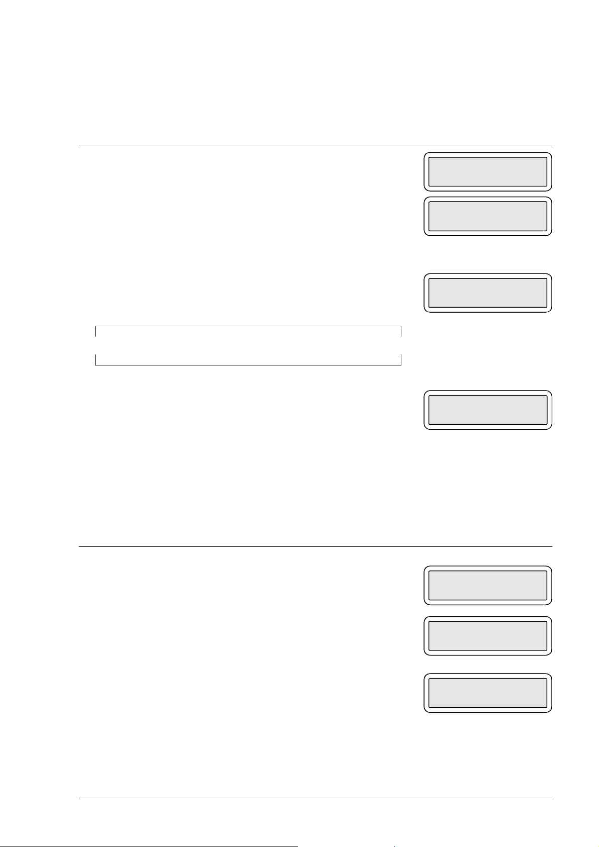
6.1.5 ASF TEST (not active with a colour print head)
This test MUST be carried out after replacing: the paper motor or the printer unit.
Setting Display
a) The facsimile machine is in standby mode.
b) Get access to the system test menu and select the ASF
TEST option
c) Place a blank sheet of paper in the ASF and then press
START: the same line is printed on both top and bottom
of sheet as in the case of the alignment test (fig. 6-2):
d) If the paper gets jammed, the message PAPER ERROR
appears on the display.
AUTOMATIC RX
09-05-95 14:58
ASF TEST
START/STOP/←/→
ASF TEST
STOP
PAPER ERROR
PRESS STOP
6.1.6 ADF TEST
This test MUST be carried out after replacing: the feeder rollers or the scanner unit.
Setting Display
a) The facsimile machine is in standby mode
b) Get access to the system test menu and select the ADF
TEST option
c) Place one or more sheets with text and pictures in the
automatic document feeder and then press START: the
documents are scanned one at a time and, at the end of
the operation, a message appears indicating the number
of documents scanned ( xx)
d) If you want to repeat the test, insert more sheets in the
feeder and press START.
AUTOMATIC RX
09-05-95 14:58
ADF TEST
START/STOP/←/→
xx: ADF TEST
STOP
XEROX DFC165 & DWC165c Service Manual 6-9
Page 92

6.1.7 LOAD DEFAULT
This procedure is used for loading the default values of the service switches for the
current country version of the facsimile machine.
Setting Display
a) The facsimile machine is in standby mode
b) Get access to the system test menu and select the LOAD
DEFAULT option
c) Press START
d) Press START once again: the default values of the U.K.
service switches are automatically set in place of the
current ones, clearing the static RAM and thus deleting
all data (reports) set by the user.
6.1.8 SCANNER SHADING
AUTOMATIC RX
09-05-95 14:58
LOAD DEFAULT
START/STOP/←/→
LOAD DEFAULT
START/STOP
This test MUST be carried out after replacing: the scanner unit, motherboard or CCD
board. It must also be carried out after making the CCD adjustment (see section 6.3).
Setting Display
a) The facsimile machine is in standby mode
b) Get access to the system test menu and select the
SCANNER SHADING option
AUTOMATIC RX
09-05-95 14:58
SCANNER SHADING
START/STOP/←/→
c) Open the console and remove the ejector roller (see
section 7.2.11)
d) Place a blank sheet (folded in two) onto the glass of the
optical reader so that it covers the glass entirely but not
the document sensor (see section 2.2.2).
6-10 XEROX DFC165 & DWC165c Service Manual
Page 93

Setting Display
e) Reassemble the roller and close the console.
f) Press START
g) Press START once again: the LED array lights up to
automatically check the white level, and the result is
SCANNER SHADING
START/STOP
SCANNER SHADING
STOP
saved to ensure correct CCD operation
Warning:
Should the blank sheet not be correctly positioned, a
beep is generated as you press START.
h) Press STOP to switch off the LED array.
6.1.9 CARRIAGE TEST
This test MUST be carried out after replacing: the carriage, carriage motor or printer
unit.
Setting Display
a) The facsimile machine is in standby mode
b) Get access to the system test menu and select the
CARRIAGE TEST option
c) Press START: the carriage starts moving from right to
left and gradually increases its field of movement until it
reaches the left-hand side of the machine, and then it
repeats this procedure.
AUTOMATIC RX
09-05-95 14:58
CARRIAGE TEST
START/STOP/←/→
CARRIAGE TEST
STOP
XEROX DFC165 & DWC165c Service Manual 6-11
Page 94

6.2 CHECKS AND ADJUSTMENTS
6.2.1 Checking the direct voltages
1) Remove the power supply/NCU assembly (see section 7.2.3) without disconnecting it from the motherboard
2) Measure the direct voltages at connector J2 on the power supply board.
PF
+28 VDC
GND
GND
J2
GND
+24 VDC
+5 VDC
+12 VDC
-12 VDC
Fig. 6-5
6-12 XEROX DFC165 & DWC165c Service Manual
Page 95
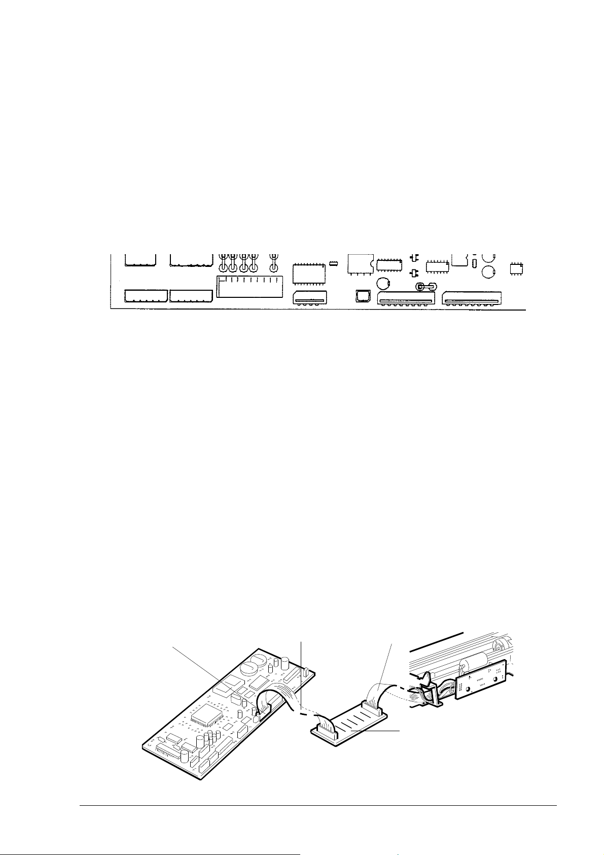
6.3 ADJUSTING THE CCD
This adjustment MUST be performed, exclusively in a laboratory, after replacing
the CCD board, and requires the following equipment:
1. a special jig (order code 98870 H)
2. a flat cable like the one that connects the CCD board to the motherboard
3. a plate with test points, which may be prepared at the laboratory, bearing in mind
that the test point signals must correspond to the following pins of connector J14
on the motherboard: RS =8, SH = 13, VIDEO = 10, GND = 4-9-11
J14
4. an oscilloscope with a memory to function as an "event counter"
5. a sample facsimile machine of the same class as the machine to be repaired.
6.3.1 Preparing for the CCD Adjustment
Before proceeding to adjust the CCD, the sample facsimile machine must be
prepared and connected to the scanner unit on which the CCD board has been
replaced.
1) Disconnect the CCD flat cable from connector J8 on the motherboard and plug
in one end of the additional flat cable in its place (see figure 6-6)
2) Plug the other end of the additional flat cable into one connector of the test point
plate and then the replaced CCD board flat cable into the remaining connector on
the plate (see figure 6-6)
CCD plate
flat cable
connector J8
additional
flat cable
Fig. 6-6
test point plate
6-13 XEROX DFC165 & DWC165c Service Manual
Page 96

3) Connect the probe of channel CH1 of the oscilloscope to the test point "VIDEO", the
probe of channel CH2 to test point "RS", the ground wires of the probes to test points
"GND" and the probe of the external trigger to test point "SH" (see figure 6-7)
GND
RS
SH
additional
flat cable
Fig. 6-7
4) Set the oscilloscope as follows:
- CH1 = 1V/ division - CH2 = 2V/ division
5) Power on the facsimile machine and then, with the START key held down, press
the * key twice in quick succession to gain direct access to the SYSTEM TEST
utilities (see section 6.1)
6) Press the < key to select SCANNER SHADING and press the START key: the LED
array will light up so that the CCD adjustment can be made.
GND
VIDEO
GND
CCD board
flat cable
6.3.2 Checking the Alignment of the CCD Board
1) Tilt the console forward, remove the document ejector roller (see section 7.2.11)
and insert the jig in its place with its printed side facing the optical reader glass, and
then close the console again.
The jig consists of several different areas (see figure 6-8)
E
BC D D CA A
Fig. 6-8
E
6-14 XEROX DFC165 & DWC165c Service Manual
Page 97

- area "A", for testing lens focussing
- area "B", for testing that the document and the CCD are centred
- area "C", for checking that the edges of the document are scanned
- area "D", for testing the black level
- area "E", for testing the scanning position
2) Check that the VIDEO signal moves parallel to the horizontal lines on the screen
and that the lines in area "D" are symmetrical and parallel to the ground line (see
figure 6-9)
CH1 200mV A 500µs 1.02 V EXT2
CH2 5V
"D" "D"
VIDEO
RS
Fig. 6-9
3) If they do not, loosen the screws on the CCD board, turn the board to the desired
position and tighten the screws (see figure 6-10)
CCD board
Fig. 6-10
screws
6-15 XEROX DFC165 & DWC165c Service Manual
Page 98

6.3.3 Checking the Lens Focus
1) Check that the VIDEO signal for areas "A" on the jig is at its maximum amplitude
(see figure 6-11)
CH1 200mV A 100µs 1.02 V EXT2
CH2 5V
"A"
VIDEO
↓
V = max
↑
RS
Fig. 6-11
2) If it is not, loosen the two screws and move the lens to the desired position (see
figure 6-12); then fix the screws in position with a drop of glue.
Fig. 6-12
lens screws
6-16 XEROX DFC165 & DWC165c Service Manual
Page 99

6.3.4 Checking That the Document and the CCD Are Centred
1) Set the EVENT COUNTER of the oscilloscope to 1037
2) Check that the VIDEO signal corresponding to area "B" of the jig has a negative
peak aligned to the T marks (a deviation of ±5 events is acceptable) (see figure
6-13)
CH1 200mV A 5µs 1.02 V EXT2
CH2 5V
→
←
±5 fronti
VIDEO
T
T
"B"
RS
EVENTS COUNT = 1037
Fig. 6-13
3) If it has not, move the plate sideways to the desired position.
4) Check that the VIDEO signal for areas "C" of the jig (on right and left) has three
negative peaks corresponding to the three lines in the same area (see figure 6-14),
and then tighten the screws.
CH1 200mV A 20µs 1.02 V EXT2
CH2 5V
"C"
VIDEO
RS
Fig. 6-14
5) Having adjusted the CCD, make the SCANNER SHADING (see section 6.1.8).
6-17 XEROX DFC165 & DWC165c Service Manual
n
.
Page 100

7. MAINTENANCE AND REPLACEMENT PROCEDURES
7.1 MAINTENANCE
The facsimile machine's maintenance includes periodic preventive procedures
(such as optical unit cleaning), and action to be taken following a message on the
display (such as the ink out message): the procedures are normally carried out by the
user so they will be described in detail in the User Guide. Here only a brief description
is provided.
7.1.1 OUT OF INK Message
The facsimile machine has a built-in counter (*) for keeping track of ink consumption, so as to provide an ink out message at the right time. When the ink present in the
cartridge runs out, the display shows the following message:
OUT OF INK
to prompt the operator to:
- replace the ink cartridge, if the print head is of the rechargeable type
- replace the entire print head, if it is of the disposable type.
If a rechargeable print head is used, the ink cartridge can be replaced several times.
When a deterioration in the printing quality is observed, after several replacements,
this means that the entire print head is to be replaced.
While replacing the cartridge only, but not the entire print head, a little ink may be
ejected, to prevent the printing area from getting dirty, when the out of ink message
appears, a sheet of paper is automatically inserted under the print carriage.
(*) Two counters on the LinkFax model, one for the monochrome print head and
another for the colour print head.
7-1 XEROX DFC165 & DWC165c Service Manual
 Loading...