

Page 1
WorkCentre® C2424
copier-printer
Service
Manual
Page 2

Page 3

WorkCentre
W
C2424
Copier-Printer
Service Manual
arning
The following servicing instructions are for use by qualified service
personnel only. To av oid personal injury, do not perform any servicing other
than that contained in the operating instructions, unless you are qualified to
do so.
®
First Printing: March 2005
Part Number: 604E13990
Page 4

Copyright
Copyright © 2005 Xerox Corporation. All Rights Reserved. Unpublished rights reserved under the
copyright laws of the United States. Contents of this publication may not be reproduced in any form
without permission of Xerox Corporation.
Copyright protection claimed includes all forms of matters of copyrightable materials and information now
allowed by statutory or judicial law or hereinafter granted, including without limitation, material generated
from the software programs which are displayed on the screen such as styles, templates, icons, screen
displays, looks, etc.
®
XEROX
Each Other
United States and/or other countries.
Acrobat
PostScript
IntelliSelect
United States and/or other countries.
Apple
Chancery
Computer, Inc. in the United States and/or other countries.
HP-GL
other countries.
IBM
or other countries.
Windows
in the United States and/or other countries.
Novell
Services
Sun
States and/or other countries.
SWOP
UNIX
Company Limited.
As an E
meets the E
U.S. marks.
, The Document Company®, the digital X®, CentreWare®, FinePoint™, infoSMART®, Made For
®
, Phaser®, PhaserSMART®, and Walk-Up™ are trademarks of Xerox Corporation in the
®
, Adobe® Reader®, Adobe Type Manager®, ATM™, Illustrator®, PageMaker®, Photoshop®,
®
, Adobe Brilliant® Screens, Adobe Garamond®, Adobe Jenson™, Birch®, Carta®,
®
, Mythos®, Quake®, and Tekton® are trademarks of Adobe Systems Incorporated in the
®
, AppleTalk®, EtherTalk®, LaserWriter®, LocalTalk®, Macintosh®, Mac OS®, TrueType®, Apple
®
, Chicago®, Geneva®, Monaco®, New York® , and QuickDraw® are trademarks of Apple
®
, HP-UX®, and PCL®are trademarks of Hewlett-Packard Corporation in the United States and/or
®
and AIX® are trademarks of International Business Machines Corporation in the United States and/
®
, Windows NT®, Windows Server™, and Wingdings® are trademarks of Microsoft Corporation
®
, NetWare®, NDPS®, NDS®, Novell Directory Services® , IPX™, and Novell Distributed Print
™
are trademarks of Novell, Incorporated in the United States and/or other countries.
SM
, Sun Microsystems™, and Solaris® are trademarks of Sun Microsystems, Incorporated in the United
®
is a trademark of SWOP, Inc.
®
is a trademark in the United States and other countries, licensed exclusively through X/Open
NERGY STAR
®
NERGY STAR guidelines for energy efficiency. The ENERGY STAR name and logo are registered
partner, Xerox Corporation has determined that this product with an ES Option
This product uses code for SHA-1 written by John Halleck, which is being used with his permission.
This product includes an implementation of LZW licensed und er U.S. Patent 4,558,302.
PANTONE
Publications for accurate color. PANTONE
®
Colors generated may not match P ANTONE-identified standards. Consult current PANTONE
®
and other Pantone, Inc. trademarks are the property of
Pantone, Inc. © Pantone, Inc., 2000.
Page 5

Organization of this Manual
Frontis - Introductory, Safety and Regulatory Information
This section contains important safety information regarding technical components, regulatory
agency requirements, and information about this manual.
Section 1 - General Information
This section cantains a general overview of the system and basic information regarding the
control panel, consumables, and the system’s physical, functional, electrical, en vironmental,
and media specifications.
Section 2 - Theory of Operation
This section contains the basic theory of operation for the entire system. It includes diagrams
and detailed operating information regarding the sub-systems (internal components), print
processes (media paths and imaging), and electronics (power supply and boards).
Section 3 - Error Codes and Messages
This section provides detailed troubleshooting procedures for the system, utilizing the
displayed control panel error codes and messages.
Section 4 - General Troubleshooting
This section covers general start-up, POST, BIST, PEST, and power supply operations of the
system to aid in troubleshooting problems not associated with a control panel message or error
code. This section also covers the Service Diagnostic functions of the system.
Section 5 - Image-Quality Troubleshooting
This section provides image-quality troubleshooting procedures for the entire system. It also
contains the various test prints available to aid in troubleshooting image-quality problems.
Section 6 - Adjustments and Calibrations
This section provides procedures for proper homing of the systems components, system
calibrations, ensuring ground integrity of the system, and resetting NVRAM.
Section 7 - Cleaning and Maintenance
This section provides basic information on cleaning and maintaining the system for optimal
operation. It also includes printer self-maintenance functions.
Section 8 - Disassembly
This section contains all the disassembly instructions for removing and replacing Xerox spared
parts.
Section 9 - Parts List
This section contains exploded diagrams and detailed parts lists for the WorkCentre C2424
Copier-Printer and the most common Xerox supplies used for this system.
Section 10 - Wiring Diagrams
This section contains the main wiring diagrams, plug-jack connector maps, and wiring
diagrams to aid in troubleshooting the PEST codes.
Service Manual i
Page 6

Manual Terms
W
Various terms are used throughout this manual to either provide additional information on a
specific topic or to warn of possible danger present during a procedure or action. Be aware of
all symbols and terms when they are used, and alwa ys read NO TE, CAUTION, and WARNING
statements.
Note
A note indicates an operating or maintenance procedure, practice or condition that is
neccessary to efficiently accomplish a task.
A note can provide additional information related to a specific subject or add a comment
on the results achieved through a previous action.
Caution
A caution indicates an operating or maintenance procedure, practice or condition that, if
not strictly observed, results in damage to, or destruction of, equipment.
arning
A warning indicates an operating or maintenance procedure, practice or condition that, if
not strictly observed, results in injury or loss of life.
ii W orkCentre C2 424 Copier-Printer
Page 7

General Safety
W
W
W
The system and recommended supplies hav e been design ed and tested to meet strict safety
requirements. Attention to the following information will ensure the continued safe operation
of the system.
Electrical Safety
■ Use the power cord supplied with the system.
■ Plug the power cord directly into a properly grounded electrical outlet.
■ Do not use a ground adapter plug to connect the system to an electrical outlet that does not
have a ground connection terminal.
■ Do not use an extension cord or power strip.
arning
Avoid the potential of electrical shock by ensuring that the system is properly grounded.
Electrical products may be hazardous if misused.
■ Do not place the system in an area where people might step on the power cord.
■ Do not place objects on the power cord.
■ Do not block the ventilation openings. These openings are provided to prev ent overheating
of the system.
■ Do not drop paper clips or staples into the system.
The power cord is attached to the system as a plug-in device on the side of the system. If it is
necessary to disconnect all electrical power from the system, disconnect the power cord from
the electrical outlet.
arning
Do not remove the cov ers or guards that are fastened with scre ws unless you are installing
optional equipment and are specifically instructed to do so. Power should be OFF when
performing these installations. Disconnect the power cord when removing covers and
guards for installing optional equipment. Except for user-installable options, there are no
parts that you can maintain or service behind these covers.
arning
The following are hazards to your safety:
■ The power cord is damaged or frayed.
■ Liquid is spilled into the system.
■ The system is exposed to water .
If any of these conditions occur:
1. Turn off the system immediately.
2. Disconnect the power cord from the electrical outlet.
3. Call an authorized service representative.
Service Manual iii
Page 8

Maintenance Safety
■ Do not attempt any maintenance procedure that is not specifically described in the
documentation supplied with your system.
■ Do not use aerosol cleaners. The use of supplies that are not approved may cause poor
performance and could create a hazardous condition.
■ Do not burn any consumables or routine maintenance items. For information on Xerox
supplies recycling programs, go to www.xerox.com/gwa
.
Operational Safety
Your system and supplies were designed and tested to meet strict safety requirements. These
include safety agency examinati on, approval, and compliance with established environmental
standards.
Your attention to the following safety guidelines helps to ensure the continued, safe operation
of your system.
System Supplies
■ Use the supplies specifically designed for your system. The use of unsuitable materials
may cause poor performance and a possible safety hazard.
■ Follow all warnings and instructions marked on, or supplied with, the system, options and
supplies.
Caution
Use of other than Genuine Xerox W orkCentre C2424 Solid Ink may affect print and copy
quality and system reliability. It is the only ink designed and manufactured under strict
quality controls by Xerox for specific use with this system. The Xerox Warranty, Service
Agreements, and Total Satisfaction Guarantee do not cover damage, malfunction, or
degradation of performance caused by use of non-Xerox supplies or consumables, or the
use of Xerox supplies not specified for this system.
Note
The Total Satisfaction Guarantee is available in the United States and Canada. Coverage
may vary outside these areas; please contact your local representative for details.
Moving the System
Caution
Parts of the system are hot. To avoid personal injury or damage to the system, allow the ink
to solidify. Run the shut-down procedure to cool the system quickly. Wait at least
30 minutes for the system to cool completely before moving or packing it.
■ Always allow the system to cool before it is moved to avoid ink spills which can damage
the system.
■ Use the shut-down procedure at the control panel Shut Down for Moving System for
best results.
iv W orkCentre C2 424 Copier-Printer
Page 9
■ Never move the system if you receive a Power Down Error-Head not Parked
2424-107
2424-109
message at the system’s control panel. This message means the system is not ready to be
moved. If the printhead is not locked, the system can be damaged during shipment.
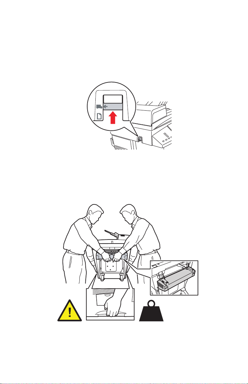
■ Always turn off the system using the power switch, located under the interface cover on
the right side of the system, and unplug all cables and cords. Do not turn off the system by
pulling the power cord or using a power-strip with an on/off switch.
■ Always secure the scanhead shipping restraint on the left side of the scanner to loc k the
scanhead before removing the scanner portion of the system. Shipping the scanner with
the scanhead unlocked can damage the scanner.
al
in
ig
r
O
ype
T
s
ic
h
ut
p
tp
ra
u
G
O
lity
a
u
Q
d
s
o
e
Pr
i-R
H
d
e
s
2-Sided
n
a
h
n
E
rd
a
d
tan
S
t
as
F
Color
Mode
B/W
utput
O
Color
Uncollated
Collated
■ Always remove the document feeder before shipping the system.
■ Always remove the scanner before shipping the system.
■ The system is heavy and must be lifted by two people. The illust rati on below shows the
proper technique for lifting the system.
42 kg
93 lbs.
■ Always move the system separately from optional Trays 3 and 4.
Service Manual v
Page 10
When shipping the system, repack the system using the original packing material and boxes or
a Xerox repackaging kit. Additional instructions for repacking the system are provided in the
repackaging kit. If you do not have all the original packaging, or are unable to repackage the
system, contact your local Xerox service representative.
Caution
Failure to repackage the system properly for shipment can result in damage to the system.
Damage to the system caused by improper moving is not covered by the Xerox warranty,
service agreement, or Total Satisfaction Guarantee.
Note
The Total Satisfaction Guarantee is available in the United States and Canada. Coverage
may vary outside these areas; please contact your local representative for details.
Operating Safety Guidelines
■ Keep hands, hair, neckties, etc., away from the exit and feed rollers.
■ Do not remove the paper source tray that you selected in either the printer driver or control
panel.
■ Do not open the doors while the system is busy.
■ Do not move the system while busy.
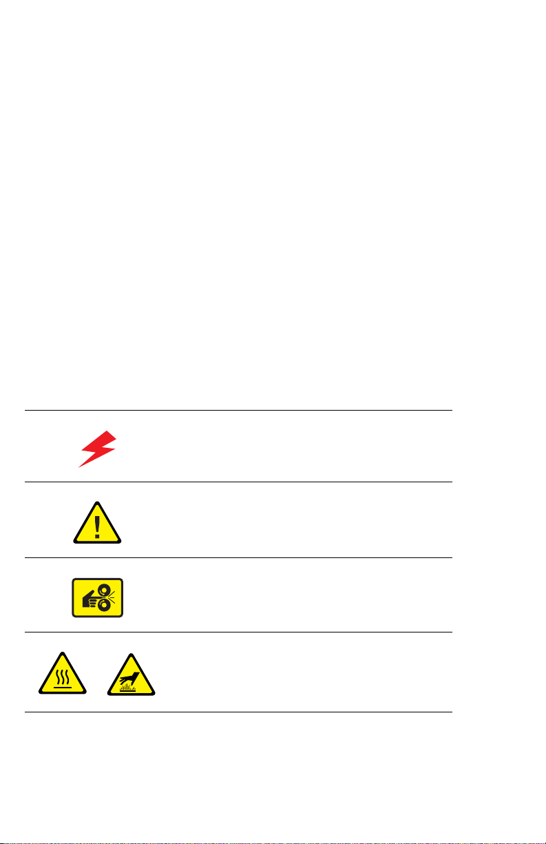
Symbols Marked on the System
Danger, high voltage.
Use caution (or draws attention to a particular
component). See the manual(s) for information.
Avoid pinching fingers in the system. Use caution to
avoid personal injury.
Hot surface on or in the system. Use caution to avoid
personal injury.
vi W orkCentre C242 4 Copier-Printer
Page 11

Electrostatic Discharge (ESD) Precautions
Some semiconductor components, and the respective sub-assemblies that contain them, are
vulnerable to damage by Electrostatic Discharge (ESD). These components include Integrated
Circuits (ICs), Large-Scale Integrated circuits (LSIs), field-effect transistors and other
semiconductor chip components. The following techniques will reduce the occurrence of
component damage caused by static electricity.
Be sure the power is off to the chassis or circuit board, and observe all other safety precautions.
■ Immediately before handling any semiconductor components assemblies, drain the
electrostatic charge from your body. This can be accomplished by touching an earth
ground source or by wearing a wrist strap device connected to an earth ground source.
Wearing a wrist strap will also prevent accumulation of additional bodily static charges.
Be sure to remove the wrist strap before applying power to the unit under test to avoid
potential shock.
■ After removing a static sensitive assembly from its anti-static bag, place it on a grounded
conductive surface. If the anti-static bag is conductive, you may ground the bag and use it
as a conductive surface.
■ Do not use freon-propelled chemicals. These can generate electrical charges sufficient to
damage some devices.
■ Do not remove a replacement component or electrical sub-assembly from its protective
package until you are ready to install it.
■ Immediately before removing the protective material from the leads of a replacement
device, touch the protective material to the chassis or circuit assembly into which the
device will be installed.
■ Minimize body motions when handling unpackaged replacement devices. Motion such as
your clothes brushing together, or lifting a foot from a carpeted floor can generate enough
static electricity to damage an electro-statically sensitive device
■ Handle IC’s and EPROM’s carefully to avoid bending pins.
■ Pay attention to the direction of parts when mounting or inserting them on Printed Circuit
Boards (PCB’s).
Service Manual vii
Page 12

Service Safety Summary
W
W
General Guidelines
For qualified service personnel only: Refer also to the preceding Power Safety
Precautions.
Avoid servicing alone: Do not perform internal service or adjustment of this product
unless another person capable of rendering first aid or resuscitation is present.
Use care when servicing with power: Dangerous voltages may exist at several
points in this product. T o avoid personal injury, do not touch exposed connections and
components while power is on. Disconnect power before removing the power supply shield or
replacing components.
Do not wear jewelry: Remove jewelry prior to servicing. Rings, necklaces, and other
metallic objects could come into contact with dangerous voltages and currents.
Power source: This product is intended to operate from a power source that will not apply
more then 264 volts RMS for a 220 volt AC outlet or 140 volts RMS for a 110 volt AC outlet
between the supply conductors or between either supply conductor and ground. A protecti ve
ground connection by way of the grounding conductor in the power cord is essential for safe
operation.
Warning Labels
Read and obey all posted warning labels. Throughout the printer, warning labels are displayed
on potentially dangerous components. As you service the printer, check to make certain that all
warning labels remain in place.
Safety Interlocks
Make sure all covers and the sy stem’s control panel are in place and all interlock switches are
functioning correctly after you have completed a service call. If you bypass an interlock switch
during a service call, use extreme caution when working on or around the system.
Servicing Electrical Components
Before starting any service procedure, switch off the printer power and unplug the power cord
from the wall outlet. If you must service the system with power applied, be aware of the
potential for electrical shock.
arning
Turning the power off by using the On/Off switch does not completely de-energize the
printer. You must also disconnect the printer power cord from the AC outlet. Position the
power cord so that it is easily accessible during servicing.
arning
Do not touch any electrical component unless you are instructed to do so by a service
procedure.
viii W orkCentre C2 424 Copier-Printer
Page 13

Servicing Mechanical Components
W
When servicing mechanical components within the printer, manually rotate drive assemblies,
rollers, and gears.
arning
Do not try to manually rotate or manually stop the drive assemblies while any printer
motor is running.
Service Manual ix
Page 14

Regulatory Specifications
United States
The equipment described in this manual generates and uses radio frequency energy. If it is not
installed properly in strict accordance with Xerox' instructions, it may cause interference with
radio and television reception or may not function properly due to interference from another
device. However, there is no guarantee that interference will not occur in a particular
installation. If this equipment does cause harmful interference to radio or television reception,
which can be determined by turning the equipment off and on, the user is encouraged to try to
correct the interference by one or more of the following measures:
■ Reorient or relocate the receiver (device being interfered with).
■ Increase the separation between the system and the receiver .
■ Connect the system into an outlet on a circuit diffe rent from that which the recei v er is
connected.
■ Route the interface cables on the system away from the receiver
■ Consult the dealer, Xerox service, or an experienced radio/television technician for
help.
Changes or modifications not expressly approved by Xerox can affect the emission and
immunity compliance and could void the user's authority to operate this product. To ensure
compliance, use shielded interface cables. A shielded parallel cable can be purchased directly
from Xerox at www.xerox.com/office/supplies
Xerox has tested this product to internationally accepted electromagnetic emission and
immunity standards. These standards are designed to mitigate interference caused or rece ived
by this product in a normal office environment. This product is also suitable for use in a
residential environment based on the lev els tested.
In the United States this product complies with the requirements of an unintentional radiato r in
part 15 of the FCC rules. Operation is subject to the following two conditions: (1) this device
may not cause harmful interference; (2) this device must accept any interference received,
including interference that may cause undesired operation.
.
Canada
This digital apparatus does not exceed the Class B limits for radio noise emissions from digital
apparatus set out in the Radio Interference Regulations of the Canadian Department of
Communications, ICES-003.
Le présent appareil numérique n'émet pas de bruits radioélectrique dépassant les limits
applicables aux appareils numériques de la classe B prescrites dans le Réglement sur le
brouillage radioélectrique édicté par le ministere des Communications du Canada, NMB-003.
European Union
Xerox Corporation declares, under our sole responsibility, that the system to which this
declaration relates is in conformity with the following standards and other normative
documents:
x W orkCentre C242 4 Copier-Printer
Page 15

Following the provisions of the Low Voltage Directive 73/23/EEC and its amendments:
EN 60950 (IEC
60950)
"Safety of Information Technology Equipment including Electrical
Business Equipment"
Following the provisions of the Electromagnetic Compatibility Directive 89/336/EEC and its
amendments:
EN 55022:1998
(CISPR 22)
EN 61000-3-2:1995
+A1:1998+A2:1998
(IEC61000-3-2)
EN 61000-3-3:1995
(IEC61000-3-3)
EN 55024:1998
(CISPR 24)
"Limits and Methods of measurement of radio interference
characteristics of Information Technology Equipment." Class B.
"Part 3: Limits - Section 2: Limits for harmonic current emissions
(equipment input current less than or equal to 16A per phase)."
"Part 3: Limits - Section 3: Limitation of voltage fluctuations and flick er in
low-voltage supply systems for equipment with rated current less than
or equal to 16A."
"Information technology equipment - Immunity characteristics - Limits
and methods of measurement. "
CISPR 24
Immunity
Phenomena Basic Standard Test Specification
Electrostatic
Discharge
Radio-Frequency
Electromagnetic
Field (radiated)
Fast Burst
Transients
Line Surge IEC 61000-4-5:1995 Combination wave
Radio-Frequency
Electromagnetic
Field (Conducted)
Line voltage dips IEC 61000-4-11:1994 >95% dip for ½ cycle @ 50 Hz
Line voltage dropout
IEC 61000-4-2:1995 6 kV Contact, 10 kV Air
IEC 61000-4-3:1995 80-1000 MHz, 3 V/m, 80% AM @ 1 KHz
IEC 61000-4-4:1995 5/50 Tr/Th ns, 5 kHz Rep. Freq
0.5 kV Signal Lines
1 kV AC Mains
2.0 kV Common mode
2.0 kV Differential mode
IEC 61000-4-6:1996 0.15 - 80 MHz, 3 V, 80% AM @ 1 kHz
30% dip for 25 cycles @ 50 Hz
IEC 61000-4-11:1994 >95% dropout for 250 cycles @ 50 Hz
This product, if used properly in accordance with the user's instructions, is neither dangerous
for the consumer nor for the environment.
A signed copy of the Declaration of Conformity for this product can be obtained from Xerox.
Service Manual xi
Page 16

xii W orkCentre C2424 Copier -Printer
Page 17

Contents
Organization of this Manual . . . . . . . . . . . . . . . . . . . . . . . . . . . . . . . . . . . . . i
General Safety . . . . . . . . . . . . . . . . . . . . . . . . . . . . . . . . . . . . . . . . . . . . . . iii
Electrostatic Discharge (ESD) Precautions. . . . . . . . . . . . . . . . . . . . . . . . .vii
Service Safety Summary . . . . . . . . . . . . . . . . . . . . . . . . . . . . . . . . . . . . . viii
Regulatory Specifications. . . . . . . . . . . . . . . . . . . . . . . . . . . . . . . . . . . . . . .x
1 General Information
System Introduction and Overview . . . . . . . . . . . . . . . . . . . . . . . . . . . . . 1-2
System Features and Configurations . . . . . . . . . . . . . . . . . . . . . . . . . . . .1-3
Standard Configurations. . . . . . . . . . . . . . . . . . . . . . . . . . . . . . . . 1-3
Front View. . . . . . . . . . . . . . . . . . . . . . . . . . . . . . . . . . . . . . . . . . . 1-4
Open View. . . . . . . . . . . . . . . . . . . . . . . . . . . . . . . . . . . . . . . . . . . 1-4
Side View with System Interfaces. . . . . . . . . . . . . . . . . . . . . . . . .1-5
Back View. . . . . . . . . . . . . . . . . . . . . . . . . . . . . . . . . . . . . . . . . . .1-5
Electronics Module. . . . . . . . . . . . . . . . . . . . . . . . . . . . . . . . . . . .1-6
Routine Maintenance Items and Consumables Life Expectancy . . . . . . . 1-7
Control Panel Layout . . . . . . . . . . . . . . . . . . . . . . . . . . . . . . . . . . . . . . . .1-8
Menu Map. . . . . . . . . . . . . . . . . . . . . . . . . . . . . . . . . . . . . . . . . . 1-11
System Specifications . . . . . . . . . . . . . . . . . . . . . . . . . . . . . . . . . . . . . . 1-12
Physical Dimensions and Clearances . . . . . . . . . . . . . . . . . . . . .1-12
Print Engine (IOT) Functional Specifications. . . . . . . . . . . . . . . .1-13
System Electrical Specifications. . . . . . . . . . . . . . . . . . . . . . . . .1-14
System Environmental Specifications. . . . . . . . . . . . . . . . . . . . . 1-14
Scanner/DADF (IIT) Specifications . . . . . . . . . . . . . . . . . . . . . . . 1-14
Tray and Media Specifications . . . . . . . . . . . . . . . . . . . . . . . . . . . . . . . .1-16
Duplex Automatic Document Feeder Guidelines. . . . . . . . . . . . . 1-17
Supported Envelopes . . . . . . . . . . . . . . . . . . . . . . . . . . . . . . . . .1-19
Media Storage Guidelines. . . . . . . . . . . . . . . . . . . . . . . . . . . . . . 1-19
Media that May Damage the System. . . . . . . . . . . . . . . . . . . . . . 1-20
2 Theory of Operation
System Overview . . . . . . . . . . . . . . . . . . . . . . . . . . . . . . . . . . . . . . . . . . .2-2
System Summaries. . . . . . . . . . . . . . . . . . . . . . . . . . . . . . . . . . . .2-2
Image Input Terminal (IIT). . . . . . . . . . . . . . . . . . . . . . . . . . . . . . . . . . . . 2-3
Major Components of the DADF and Scanner. . . . . . . . . . . . . . . .2-3
Document Feeder Functions. . . . . . . . . . . . . . . . . . . . . . . . . . . . . 2-4
Document Feeder Paper Path and Imaging. . . . . . . . . . . . . . . . . . 2-6
Scanner Assembly Functions . . . . . . . . . . . . . . . . . . . . . . . . . . . . 2-7
Scanner and Document Feeder Calibration. . . . . . . . . . . . . . . . . . 2-8
System Electronics. . . . . . . . . . . . . . . . . . . . . . . . . . . . . . . . . . . . . . . . .2-10
Exit Module (MEP) Board . . . . . . . . . . . . . . . . . . . . . . . . . . . . . . 2-11
Scanner Power Supply . . . . . . . . . . . . . . . . . . . . . . . . . . . . . . . .2-11
Service Manual xiii
Page 18

Electronics Module . . . . . . . . . . . . . . . . . . . . . . . . . . . . . . . . . . 2-11
Image Output Terminal (IOT) Sub-Assemblies . . . . . . . . . . . . . . . . . . . 2-15
Paper Path and Paper Pick . . . . . . . . . . . . . . . . . . . . . . . . . . . . . . . . . . 2-18
Paper Pick for Tray 1 . . . . . . . . . . . . . . . . . . . . . . . . . . . . . . . . . 2-18
Paper Pick for Trays 2 - 4 . . . . . . . . . . . . . . . . . . . . . . . . . . . . . 2-19
2-Sided (Duplex) Printing . . . . . . . . . . . . . . . . . . . . . . . . . . . . . 2-20
Sensor Locations. . . . . . . . . . . . . . . . . . . . . . . . . . . . . . . . . . . . 2-21
System Motors, Solenoids, and Drive. . . . . . . . . . . . . . . . . . . . . . . . . . 2-22
Process Drive. . . . . . . . . . . . . . . . . . . . . . . . . . . . . . . . . . . . . . . 2-23
Media Path Drive . . . . . . . . . . . . . . . . . . . . . . . . . . . . . . . . . . . . 2-24
The Print Process . . . . . . . . . . . . . . . . . . . . . . . . . . . . . . . . . . . . . . . . . 2-25
Drum Preparation . . . . . . . . . . . . . . . . . . . . . . . . . . . . . . . . . . . 2-26
Ink Loader . . . . . . . . . . . . . . . . . . . . . . . . . . . . . . . . . . . . . . . . . 2-27
Printhead . . . . . . . . . . . . . . . . . . . . . . . . . . . . . . . . . . . . . . . . . . 2-28
Drum Assembly. . . . . . . . . . . . . . . . . . . . . . . . . . . . . . . . . . . . . 2-34
Transfix System. . . . . . . . . . . . . . . . . . . . . . . . . . . . . . . . . . . . . 2-36
Drum Maintenance System . . . . . . . . . . . . . . . . . . . . . . . . . . . . 2-37
Purge System . . . . . . . . . . . . . . . . . . . . . . . . . . . . . . . . . . . . . . 2-38
Transfixing and Exiting . . . . . . . . . . . . . . . . . . . . . . . . . . . . . . . 2-40
Transfix and Print Speeds . . . . . . . . . . . . . . . . . . . . . . . . . . . . . 2-44
Configuration Card Personality Parameters. . . . . . . . . . . . . . . . . . . . . . 2-45
3 Error Messages and Codes
Introduction. . . . . . . . . . . . . . . . . . . . . . . . . . . . . . . . . . . . . . . . . . . . . . . 3-2
Power-Up Error Messages and LED Codes . . . . . . . . . . . . . . . . . . . . . . . 3-3
BIST Error Reporting . . . . . . . . . . . . . . . . . . . . . . . . . . . . . . . . . . 3-3
POST Error Reporting . . . . . . . . . . . . . . . . . . . . . . . . . . . . . . . . . 3-4
PEST Error Reporting . . . . . . . . . . . . . . . . . . . . . . . . . . . . . . . . . 3-7
Fault Code Error Message Troubleshooting. . . . . . . . . . . . . . . . . . . . . . . 3-8
Fault Code Error Reporting . . . . . . . . . . . . . . . . . . . . . . . . . . . . . 3-8
Interpreting Fault Codes. . . . . . . . . . . . . . . . . . . . . . . . . . . . . . . . 3-8
1,000.4x Error - 525-Sheet Feeder Faults . . . . . . . . . . . . . . . . . . 3-9
2,0XX.4x Error - I/O Circuit Board Fault. . . . . . . . . . . . . . . . . . . 3-10
3,0XX.6x - IPC Program Faults . . . . . . . . . . . . . . . . . . . . . . . . . 3-10
4,0XX.4x Errors - Process Control System Fault . . . . . . . . . . . . 3-11
5,0XX.4x Errors - Y-Axis Sub-System Fault. . . . . . . . . . . . . . . . 3-14
6,0XX.4x Errors - X-Axis Fault . . . . . . . . . . . . . . . . . . . . . . . . . . 3-15
7,0XX.4x Errors - Process Motor Gearbox Faults. . . . . . . . . . . . 3-16
8,0XX.xx Error - Wiper/Media Path Gearbox Faults . . . . . . . . . . 3-20
9,0XX.xx Errors - Ink Loader Faults. . . . . . . . . . . . . . . . . . . . . . 3-22
11,0XX.xx Errors - Electronics Module Interface Fault. . . . . . . . 3-23
13,0XX.xx Errors - Thermal Faults. . . . . . . . . . . . . . . . . . . . . . . 3-24
19,0XX.xx Errors - Printhead Calibration faults.. . . . . . . . . . . . . 3-33
31,0XX.4x Errors - Mechanical Initialization Jam . . . . . . . . . . . . 3-34
33,0XX.xx Errors - Tray Manager Device Faults. . . . . . . . . . . . . 3-35
34,0XX.xx Errors - Printhead NVRAM Faults . . . . . . . . . . . . . . . 3-35
xiv W orkCentre C2424 Copier -Printer
Page 19

36,000.40 Errors - Drum Maintenance Faults. . . . . . . . . . . . . . .3-36
37,0XX.xx Errors - PEST Faults . . . . . . . . . . . . . . . . . . . . . . . . . 3-37
39,0XX.xx Errors - Document Feeder / Scanner Unit Faults . . . . 3-46
3-Digit Jam Codes . . . . . . . . . . . . . . . . . . . . . . . . . . . . . . . . . . . . . . . . .3-49
Jam Code Definition Table . . . . . . . . . . . . . . . . . . . . . . . . . . . . . 3-50
4 General Troubleshooting
Introduction . . . . . . . . . . . . . . . . . . . . . . . . . . . . . . . . . . . . . . . . . . . . . . . 4-2
Hidden Service Menu. . . . . . . . . . . . . . . . . . . . . . . . . . . . . . . . . . . . . . . . 4-2
Service Diagnostics . . . . . . . . . . . . . . . . . . . . . . . . . . . . . . . . . . . . . . . . . 4-4
Service Diagnostics Menu Functions . . . . . . . . . . . . . . . . . . . . . . 4-4
Entering Service Diagnostics . . . . . . . . . . . . . . . . . . . . . . . . . . . . 4-5
Service Diagnostic Menu Definition Tables. . . . . . . . . . . . . . . . . .4-6
Check Menu / Activators Definition Tables. . . . . . . . . . . . . . . . . . . . . . .4-15
Check / Activators Menu. . . . . . . . . . . . . . . . . . . . . . . . . . . . . . .4-15
Check Shafts Menu. . . . . . . . . . . . . . . . . . . . . . . . . . . . . . . . . . .4-18
Check Fans Menu . . . . . . . . . . . . . . . . . . . . . . . . . . . . . . . . . . . . 4-24
Check Heaters Menu. . . . . . . . . . . . . . . . . . . . . . . . . . . . . . . . . .4-25
Check Paper Path Menu . . . . . . . . . . . . . . . . . . . . . . . . . . . . . . .4-27
Check Drive Menu. . . . . . . . . . . . . . . . . . . . . . . . . . . . . . . . . . . .4-35
Check Drum Menu . . . . . . . . . . . . . . . . . . . . . . . . . . . . . . . . . . .4-40
Check Motors Menu . . . . . . . . . . . . . . . . . . . . . . . . . . . . . . . . . . 4-45
Check Misc Menu. . . . . . . . . . . . . . . . . . . . . . . . . . . . . . . . . . . . 4-48
System Power-Up Sequence . . . . . . . . . . . . . . . . . . . . . . . . . . . . . . . . . 4-54
Mechanical Initialization of the Print Engine . . . . . . . . . . . . . . . .4-55
Head Cleaning Cycle Performance . . . . . . . . . . . . . . . . . . . . . . .4-57
Electrical Troubleshooting . . . . . . . . . . . . . . . . . . . . . . . . . . . . . . . . . . .4-58
Electronics Module. . . . . . . . . . . . . . . . . . . . . . . . . . . . . . . . . . .4-58
Document Feeder Lamp Does Not Turn ON . . . . . . . . . . . . . . . . 4-59
Document Feeder Does Not Feed Media. . . . . . . . . . . . . . . . . . . 4-59
Scanner Scanhead Does Not Move. . . . . . . . . . . . . . . . . . . . . . . 4-60
Scanhead Motion is Not Smooth and Continuous . . . . . . . . . . . 4-60
Scanner Lamp Does Not Turn On. . . . . . . . . . . . . . . . . . . . . . . . 4-60
Control Panel is Malfunctioning . . . . . . . . . . . . . . . . . . . . . . . . . 4-60
Exit Module (MEP) is Malfunctioning . . . . . . . . . . . . . . . . . . . . .4-62
System Fails to Power-Up. . . . . . . . . . . . . . . . . . . . . . . . . . . . . .4-62
System Energy Star Mode Troubleshooting . . . . . . . . . . . . . . . . 4-64
System Reports Missing Maintenance Kit . . . . . . . . . . . . . . . . . 4-65
System Reports Missing Waste Tray . . . . . . . . . . . . . . . . . . . . .4-65
System Features Not Available . . . . . . . . . . . . . . . . . . . . . . . . . .4-65
525-Sheet Feeder Does Not Function . . . . . . . . . . . . . . . . . . . . .4-66
Non-Specific Electronics Failure. . . . . . . . . . . . . . . . . . . . . . . . .4-67
Verifying Scanner Power Supply Operation . . . . . . . . . . . . . . . .4-70
Verifying Power Supply Operation - Print Engine . . . . . . . . . . . . 4-71
Measuring AC Power Supply Voltages . . . . . . . . . . . . . . . . . . . . 4-72
Measuring DC Power Supply Voltages . . . . . . . . . . . . . . . . . . . . 4-73
Service Manual xv
Page 20

Ensuring Ground Integrity . . . . . . . . . . . . . . . . . . . . . . . . . . . . . 4-73
Testing Motor and Solenoid Resistances. . . . . . . . . . . . . . . . . . 4-75
Paper Path and Media-Based Problems . . . . . . . . . . . . . . . . . . . . . . . . 4-76
Media-Based Problems . . . . . . . . . . . . . . . . . . . . . . . . . . . . . . . 4-76
Checking the Process and Media Path Drive . . . . . . . . . . . . . . . 4-78
Operating System and Application Problems . . . . . . . . . . . . . . . . . . . . 4-79
Testing Communications Ports . . . . . . . . . . . . . . . . . . . . . . . . . 4-79
Network Problems. . . . . . . . . . . . . . . . . . . . . . . . . . . . . . . . . . . . . . . . . 4-81
Obtaining Serial Back Channel Trace . . . . . . . . . . . . . . . . . . . . . 4-82
5 Image-Quality Troubleshooting
Image-Quality Problems Overview . . . . . . . . . . . . . . . . . . . . . . . . . . . . . 5-2
Service Technician RIP Procedure. . . . . . . . . . . . . . . . . . . . . . . . 5-3
Isolating a Copy/Scan Malfunction to the Scanner/DADF. . . . . . . 5-3
DADF Image-Quality Problems . . . . . . . . . . . . . . . . . . . . . . . . . . 5-4
Dark Streaks on the Copied Image. . . . . . . . . . . . . . . . . . . . . . . . 5-4
Skewed Copy Image . . . . . . . . . . . . . . . . . . . . . . . . . . . . . . . . . . 5-5
Copy Image is Lighter/Darker than the Original . . . . . . . . . . . . . 5-5
Fuzzy Text/Image. . . . . . . . . . . . . . . . . . . . . . . . . . . . . . . . . . . . . 5-6
Copied Image Colors Do Not Match the Original . . . . . . . . . . . . . 5-7
Scanner Image Quality Problems . . . . . . . . . . . . . . . . . . . . . . . . . . . . . . 5-8
Dark Streaks on the Copied Image. . . . . . . . . . . . . . . . . . . . . . . . 5-8
Copied Image is Skewed . . . . . . . . . . . . . . . . . . . . . . . . . . . . . . . 5-8
Copied Image is Lighter/Darker than the Original . . . . . . . . . . . . 5-8
Copy Image Colors Do Not Match the Original. . . . . . . . . . . . . . . 5-9
Fuzzy Text/Image. . . . . . . . . . . . . . . . . . . . . . . . . . . . . . . . . . . . 5-10
Diagnosing IOT (Print Engine) Print-Quality Problems . . . . . . . . . . . . . 5-1 1
Random Light Stripes . . . . . . . . . . . . . . . . . . . . . . . . . . . . . . . . 5-12
Predominate Light Stripes. . . . . . . . . . . . . . . . . . . . . . . . . . . . . 5-13
Smudges or Smears . . . . . . . . . . . . . . . . . . . . . . . . . . . . . . . . . 5-14
The Printed Image Is Too Light or Too Dark . . . . . . . . . . . . . . . 5-15
No Image is Being Printed. . . . . . . . . . . . . . . . . . . . . . . . . . . . . 5-15
Color is Uneven or Color is Wrong . . . . . . . . . . . . . . . . . . . . . . 5-16
Streaks or Lines Down the Print . . . . . . . . . . . . . . . . . . . . . . . . 5-17
Scratches or Marks Parallel to the Long Axis of Printing,
Particularly with Transparencies . . . . . . . . . . . . . . . . . . . . . 5-19
There is ink on the White Portion of the Printed Page . . . . . . . . 5-21
Fuzzy Text . . . . . . . . . . . . . . . . . . . . . . . . . . . . . . . . . . . . . . . . . 5-22
Poor Primary Color Fills. . . . . . . . . . . . . . . . . . . . . . . . . . . . . . . 5-24
Ghosting . . . . . . . . . . . . . . . . . . . . . . . . . . . . . . . . . . . . . . . . . . 5-25
Poor Small Text Resolution . . . . . . . . . . . . . . . . . . . . . . . . . . . . 5-26
Vertical Lines Appear Wavy . . . . . . . . . . . . . . . . . . . . . . . . . . . . 5-27
Oil Streaks on Print . . . . . . . . . . . . . . . . . . . . . . . . . . . . . . . . . . 5-28
Incomplete Image Transfer to Paper . . . . . . . . . . . . . . . . . . . . . 5-29
Ink Smears on First Printed Side of Duplex Print. . . . . . . . . . . . 5-30
Repeating Print Defects on Print . . . . . . . . . . . . . . . . . . . . . . . . 5-31
xvi W orkCentre C242 4 Copier-Printer
Page 21

White Stripes (Pinstripes). . . . . . . . . . . . . . . . . . . . . . . . . . . . . . 5-32
Wrinkling . . . . . . . . . . . . . . . . . . . . . . . . . . . . . . . . . . . . . . . . . .5-33
Image is Offset or Cut-Off. . . . . . . . . . . . . . . . . . . . . . . . . . . . . . 5-34
Poor Ink Adhesion, Poor Image Durability . . . . . . . . . . . . . . . . . 5-34
Analyzing Service Test Prints. . . . . . . . . . . . . . . . . . . . . . . . . . . . . . . . .5-35
Test Print Examples . . . . . . . . . . . . . . . . . . . . . . . . . . . . . . . . . . 5-35
6 Adjustments and Calibrations
System Alignments and Adjustments. . . . . . . . . . . . . . . . . . . . . . . . . . . . 6-2
Wiper Alignment. . . . . . . . . . . . . . . . . . . . . . . . . . . . . . . . . . . . . .6-2
Print Engine Component Home Positions and Indicators. . . . . . . . . . . . . 6-4
Homing the Printhead Wiper. . . . . . . . . . . . . . . . . . . . . . . . . . . . .6-4
Homing the Head Tilt Gear . . . . . . . . . . . . . . . . . . . . . . . . . . . . . . 6-5
Homing the Process Gear Drive Train. . . . . . . . . . . . . . . . . . . . . . 6-8
Manual DADF to Scanner Calibration . . . . . . . . . . . . . . . . . . . . . .6-9
Jet Substitution Mode . . . . . . . . . . . . . . . . . . . . . . . . . . . . . . . . . . . . . .6-12
Resetting NVRAM . . . . . . . . . . . . . . . . . . . . . . . . . . . . . . . . . . . . . . . . . 6-13
7 Cleaning and Maintenance
Inspection . . . . . . . . . . . . . . . . . . . . . . . . . . . . . . . . . . . . . . . . . . . . . . . .7-2
System Self-Maintenance. . . . . . . . . . . . . . . . . . . . . . . . . . . . . . . . . . . . . 7-3
Printhead Maintenance Cycle (Eliminate Light Stripes). . . . . . . . .7-3
Paper Preheater Cleaning (Remove Print Smears). . . . . . . . . . . .7-4
Transfix Roller Oiling . . . . . . . . . . . . . . . . . . . . . . . . . . . . . . . . . .7-4
Drum Cleaning - Chase Page . . . . . . . . . . . . . . . . . . . . . . . . . . . .7-4
Service Cleaning and Maintenance Procedures . . . . . . . . . . . . . . . . . . . . 7-5
Cleaning for Print-Quality Problems. . . . . . . . . . . . . . . . . . . . . . . . . . . . . 7-6
Media Jams and Paper Pick Cleaning Procedures . . . . . . . . . . . . 7-7
Pick Roller Cleaning Methods. . . . . . . . . . . . . . . . . . . . . . . . . . . .7-7
Cleaning the Drum Temperature Sensor. . . . . . . . . . . . . . . . . . . .7-8
Maintenance Kit . . . . . . . . . . . . . . . . . . . . . . . . . . . . . . . . . . . . . . . . . . . . 7-9
Waste Tray . . . . . . . . . . . . . . . . . . . . . . . . . . . . . . . . . . . . . . . . . .7-9
Lubrication. . . . . . . . . . . . . . . . . . . . . . . . . . . . . . . . . . . . . . . . . . . . . . .7-10
8 Service Parts Disassembly
Overview . . . . . . . . . . . . . . . . . . . . . . . . . . . . . . . . . . . . . . . . . . . . . . . . .8-2
Standard Orientation of the System . . . . . . . . . . . . . . . . . . . . . . .8-2
General Notes on Disassembly. . . . . . . . . . . . . . . . . . . . . . . . . . .8-3
Image Input Terminal (DADF and Scanner) . . . . . . . . . . . . . . . . . . . . . . . 8-4
Duplex Automatic Document Feeder. . . . . . . . . . . . . . . . . . . . . . . 8-4
DADF Front Cover. . . . . . . . . . . . . . . . . . . . . . . . . . . . . . . . . . . . .8-5
Scanner Assembly . . . . . . . . . . . . . . . . . . . . . . . . . . . . . . . . . . . .8-6
Control Panel . . . . . . . . . . . . . . . . . . . . . . . . . . . . . . . . . . . . . . . . 8-7
Service Manual xvii
Page 22

Image Output Terminal (Print Engine). . . . . . . . . . . . . . . . . . . . . . . . . . . 8-7
Covers. . . . . . . . . . . . . . . . . . . . . . . . . . . . . . . . . . . . . . . . . . . . . . . . . . . 8-8
Output Paper Tray Assembly . . . . . . . . . . . . . . . . . . . . . . . . . . . . 8-8
Front Door / Tray 1 Assembly . . . . . . . . . . . . . . . . . . . . . . . . . . 8-10
Right and Left Side Covers . . . . . . . . . . . . . . . . . . . . . . . . . . . . 8-11
Rear Cover and EMI Shield . . . . . . . . . . . . . . . . . . . . . . . . . . . . 8-12
Imaging. . . . . . . . . . . . . . . . . . . . . . . . . . . . . . . . . . . . . . . . . . . . . . . . . 8-13
Ink Loader Assembly . . . . . . . . . . . . . . . . . . . . . . . . . . . . . . . . . 8-13
Y-Axis Drum Belt, Y-Axis Tension Spring,
and Y-Axis Motor Assembly. . . . . . . . . . . . . . . . . . . . . . . . . 8-14
Printhead Assembly, Right and Left Printhead Restraints . . . . . 8-16
X-Axis Bias Spring. . . . . . . . . . . . . . . . . . . . . . . . . . . . . . . . . . . 8-23
Printhead Wiper. . . . . . . . . . . . . . . . . . . . . . . . . . . . . . . . . . . . . 8-24
Media Release Blade (Stripper) Carriage Assembly,
and Transfix Roller. . . . . . . . . . . . . . . . . . . . . . . . . . . . . . . . 8-26
Paper Preheater and Deskew Assembly. . . . . . . . . . . . . . . . . . . 8-27
Duplex Roller. . . . . . . . . . . . . . . . . . . . . . . . . . . . . . . . . . . . . . . 8-29
Transfix Load Module . . . . . . . . . . . . . . . . . . . . . . . . . . . . . . . . 8-30
Transfix Camshaft Assembly . . . . . . . . . . . . . . . . . . . . . . . . . . . 8-34
Drum Maintenance Camshaft Assembly . . . . . . . . . . . . . . . . . . 8-35
Drum Maintenance Pivot Plate Assembly . . . . . . . . . . . . . . . . . 8-36
Drum Assembly. . . . . . . . . . . . . . . . . . . . . . . . . . . . . . . . . . . . . 8-37
Purge Pressure Pump . . . . . . . . . . . . . . . . . . . . . . . . . . . . . . . . 8-41
Paper Path . . . . . . . . . . . . . . . . . . . . . . . . . . . . . . . . . . . . . . . . . . . . . . . 8-42
Exit Module Assembly (MEP). . . . . . . . . . . . . . . . . . . . . . . . . . . 8-42
Paper Guides . . . . . . . . . . . . . . . . . . . . . . . . . . . . . . . . . . . . . . . 8-44
Take Away Roller . . . . . . . . . . . . . . . . . . . . . . . . . . . . . . . . . . . . 8-48
Pick Assembly . . . . . . . . . . . . . . . . . . . . . . . . . . . . . . . . . . . . . . 8-49
Tray Lift Motor. . . . . . . . . . . . . . . . . . . . . . . . . . . . . . . . . . . . . . 8-51
Motors, Gears, Solenoids, Clutches, and Fans . . . . . . . . . . . . . . . . . . . 8-52
Media Drive Gearbox with Two Clutches and Solenoid . . . . . . . 8-52
Tray 1 (MPT) Pick Solenoid. . . . . . . . . . . . . . . . . . . . . . . . . . . . 8-54
Process Drive Motor and Gearbox. . . . . . . . . . . . . . . . . . . . . . . 8-55
X-Axis Motor Assembly . . . . . . . . . . . . . . . . . . . . . . . . . . . . . . . 8-57
Head Tilt Compound Gear . . . . . . . . . . . . . . . . . . . . . . . . . . . . . 8-58
Electronics. . . . . . . . . . . . . . . . . . . . . . . . . . . . . . . . . . . . . . . . . . . . . . . 8-59
Scanner Power Supply. . . . . . . . . . . . . . . . . . . . . . . . . . . . . . . . 8-59
Exit Module (MEP) Board. . . . . . . . . . . . . . . . . . . . . . . . . . . . . . 8-60
Electronics Module . . . . . . . . . . . . . . . . . . . . . . . . . . . . . . . . . . 8-61
Back Frame and Printer Stabilizer . . . . . . . . . . . . . . . . . . . . . . . 8-63
Wave Amp Board. . . . . . . . . . . . . . . . . . . . . . . . . . . . . . . . . . . . 8-65
I/O Board . . . . . . . . . . . . . . . . . . . . . . . . . . . . . . . . . . . . . . . . . . 8-66
Drum Heater Relay Board . . . . . . . . . . . . . . . . . . . . . . . . . . . . . 8-67
NVRAM Replacement. . . . . . . . . . . . . . . . . . . . . . . . . . . . . . . . . 8-68
xviii W orkCentre C242 4 Copier-Printer
Page 23

9 Parts Lists
Serial Number Format . . . . . . . . . . . . . . . . . . . . . . . . . . . . . . . . . . . . . . .9-2
Using the Parts List . . . . . . . . . . . . . . . . . . . . . . . . . . . . . . . . . . . . . . . . .9-3
Covers . . . . . . . . . . . . . . . . . . . . . . . . . . . . . . . . . . . . . . . . . . . . . 9-4
Imaging . . . . . . . . . . . . . . . . . . . . . . . . . . . . . . . . . . . . . . . . . . . . 9-6
Paper Path . . . . . . . . . . . . . . . . . . . . . . . . . . . . . . . . . . . . . . . . . . 9-8
Motors, Gears, Solenoids, Clutches, Sensors, Fans
and Backframe . . . . . . . . . . . . . . . . . . . . . . . . . . . . . . . . . . .9-10
Electronics Module, Circuit Boards and Cables. . . . . . . . . . . . . . 9-12
Sensors and Flags (Actuators) . . . . . . . . . . . . . . . . . . . . . . . . . . 9-14
Xerox Supplies. . . . . . . . . . . . . . . . . . . . . . . . . . . . . . . . . . . . . . . . . . . . 9-16
10 Wiring Diagrams
Plug/Jack Locator Table. . . . . . . . . . . . . . . . . . . . . . . . . . . . . . . . . . . . . 10-2
Scanner/DADF Functional Diagrams. . . . . . . . . . . . . . . . . . . . . . 10-5
Main Block Wiring Diagram . . . . . . . . . . . . . . . . . . . . . . . . . . . . 10-6
Main Block Wiring Diagram (Continued) . . . . . . . . . . . . . . . . . . 10-7
Scanner/Exit Module Power Supply
and MEP (Exit Module) Board . . . . . . . . . . . . . . . . . . . . . . . 10-8
Right-Side Wiring Diagram. . . . . . . . . . . . . . . . . . . . . . . . . . . . . 10-9
Right-Side Wiring Diagram (Continued). . . . . . . . . . . . . . . . . .10-10
Left-Side Wiring Diagram. . . . . . . . . . . . . . . . . . . . . . . . . . . . .10-11
Left-Side Wiring Diagram (Continued) . . . . . . . . . . . . . . . . . . .10-12
Inside Front Wiring Diagram. . . . . . . . . . . . . . . . . . . . . . . . . . . 10-13
Inside Top Wiring Diagram. . . . . . . . . . . . . . . . . . . . . . . . . . . . 10-14
Inside Top Wiring Diagram (continued) . . . . . . . . . . . . . . . . . . 10-15
Electronics Module. . . . . . . . . . . . . . . . . . . . . . . . . . . . . . . . . .10-16
A Appendix
Control Panel Menu Map . . . . . . . . . . . . . . . . . . . . . . . . . . . . . . . . . . . . .A-2
Control Panel Menu Map -continued-. . . . . . . . . . . . . . . . . . . . . .A-3
Control Panel Menu Map -continued-. . . . . . . . . . . . . . . . . . . . . .A-4
Media Margin Specification Table. . . . . . . . . . . . . . . . . . . . . . . . .A-5
Paper Weight Equivalence Table. . . . . . . . . . . . . . . . . . . . . . . . . .A-6
On-Site Printhead Troubleshooting Checklist . . . . . . . . . . . . . . . .A-7
Service Manual xix
Page 24

xx W orkCentre C2 424 Copier-Printer
Page 25

General Information
In this chapter...
■ System Introduction and Overview
■ System Features and Configurations
■ Routine Maintenance Items and Consumables Life Expectancy
■ Control Panel Layout
■ System Specifications
■ Tray and Media Specifications
Section
1
Page 26
System Introduction and Overview
02
The Xerox WorkCentre® C2424 Copier-Printer Service Manual is the primary
document used for repairing, maintaining, and troubleshooting the system.
To ensure understanding of this product, complete the Xerox WorkCentre C2424
Service Training Program.
s2424-0
1-2 W orkCentre C2424 Service Manual
Page 27

System Features and Configurations
This section covers the basic system and its specifications. For more detailed
information on the system’s internal components, such as main assemblies, power
supply, circuit boards, sensors, paper path, and functions, see Section 2, "Theory of
Operation" on page 2-1.
Standard Configurations
The WorkCentre C2424 is offered in three configurations.
■ DN = System with 256 MB RAM
■ DP = System with 256 MB RAM, 1 525-sheet high capacity feeder, and a
cart.
■ DX = System with 512 MB RAM, 1 525-sheet high capacity feeder, cart,
plus Scansoft applications.
General Information 1-3
Page 28
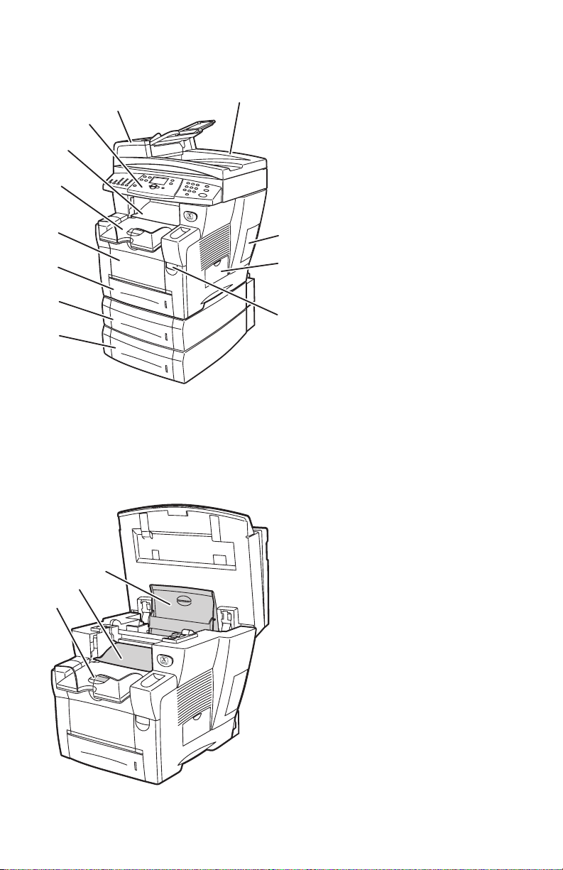
Front View
2424-080
1
2
3
4
10
11
12
71
1
7
6
5
Open View
1. Tray 4 (optional 525-Sheet
8
9
Feeder)
2. Tray 3 (optional 525-Sheet
Feeder)
3. Tray 2 (525-sheet capacity)
4. Tray 1 (100-sheet capacity,
custom size and manual feed)
5. Output tray
6. Exit cover
7. Control panel
8. DADF front cover
9. Duplex Automatic Document
Feeder (DADF)
10. Interface (I/O) cover
11. Waste tray/maintenance kit side
door
12. Front cover release (product
serial number is behind the
front cover)
1. Short paper stop
2. Exit cover
3. Ink cover
3
2
2424-1
1-4 W orkCentre C2424 Service Manual
Page 29
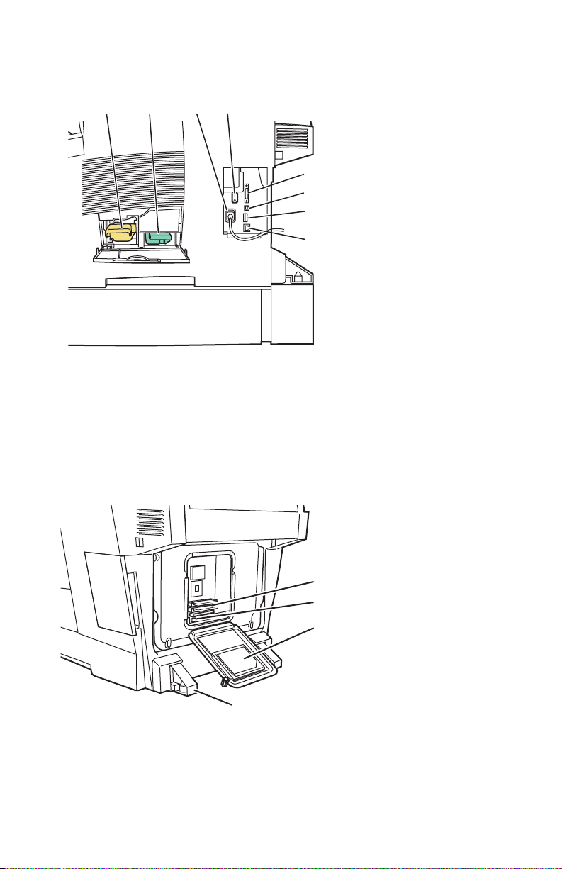
Side View with System Interfaces
2424-081
1
4
1
3
2
2
3
5
6
7
8
Back View
1. Maintenance kit
2. Waste tray
3. Power cord connection
4. Power switch
5. Scanner cable connection
6. USB connection
7. Configuration card
8. Ethernet 10/100 Base-T
connection
1. RAM slots
2. NVRAM chip
3. Hard drive
4. Stabilizer
4
s2424-267
General Information 1-5
Page 30

Electronics Module
The system’s main electronics and power supply are enclosed in a metal case called
the Electronics Module. The rear panel allows access to the electronics module,
RAM, and NVRAM chips. The system’s hard drive is mounted on the rear panel.
When installing a new electronics module in the system, the following components
need to be transferred from the old main board.
■ Hard Drive
■ Configuration Card
■ Memory (1 or 2 DIMMs)
■ NVRAM (8-pin socketed chip)
Note
See the illustrations on page 1-5 for locating the above components.
1-6 W orkCentre C2424 Service Manual
Page 31

Routine Maintenance Items and Consumables
s2424-005
Document Feed Roller
Life Expectancy
Ink Sticks
1
2
3
4
Pad
Maintenance Kit
Waste Tray
Routine Maintenance Items: Consumable:
Extended-Capacity
Maintenance Kit
Standard-Capacity
Maintenance Kit
Waste Tray Empty every 5 Purges
DADF Pick Rollers and
Separator Pad
*Consumable capacity is based on 5% coverage per color on plain A4/Letter paper.
30,000 cycles (0-20%
coverage)
20,000 (20-100%
coverage)
10,000 cycles
(~35 g)
50,000 scans
Ink 1220 prints per stick*
General Information 1-7
Page 32

Control Panel Layout
72
The control panel
■ Displays the system’s operating status or errors and warnings.
■ Prompts to load paper, replace supplies, or clear jams.
■ Enables selection settings for print, copy, and scan jobs.
■ Displays menus that enable changing the system’s settings and accesses tools to
help resolve problems.
The control panel is divided into three major areas.
2
1
2
2
2
1
11
2424-1
Left side:
Copying and scanning function
buttons and LEDs
Middle:
Graphic display screen,
mode buttons, menu
navigation, shortcut buttons
and status LEDs
Right side
Numeric keypad, Clear/Clear
All, Stop, and Start buttons
1-8 W orkCentre C2424 Service Manual
Page 33

Control Panel Left
2424-173
2
1
2
2
2
1
11
1
2
3
4
5
The left side of the control panel contains the following copy and scan function buttons and
LEDs. A green LED shows the current selection.
More details about using these buttons are provided in the Copying and Scanning sections in
the customers WorkCentre C2424 User Guide.
1. Output button and LEDs (copy only)
Press to select Uncollated or Collated for your copies.
2. Color Mode button and LEDs
Press to select B/W (black and white) or Color for your copy or scan job.
3. 2-Sided button and LEDs
Press to select whether the original is 2-sided and whether you want the output 2-sided.
4. Output Quality button and LEDs
Press to select the output quality for the copy job.
5. Output Type button and LEDs
Press to select the type of original for your copy or scan job.
General Information 1-9
Page 34

Control Panel Middle
1
2
3
4
14
15
16
5
7
6
1213
1. Original Size button
Press to jump to Original Size option on
the menu.
2. Lighten/Darken button
Press to jump to the Lighten/Darken
option on the menu.
3. Reduce/Enlarge button
Press to jump to Reduce/Enlarge option
on the menu.
4. Paper Supply button
Press to jump to the Paper Supply option
on the menu.
5. Copy button
Press to display the Copy menu on the
graphic display.
6. Scan button
Press to display the Scan menu on the
graphic display.
7. Graphic display shows status messages
and menus.
8. Up Arrow button
Scrolls upward.
8
9
11 10
2424-174
9. Enter button
The menu option selected.
10. Status Indicator LED:
Blinking green = System is busy or in
Standby or PowerSaver mode
Steady green = Ready
11. Down Arrow button
Scrolls downward.
12. Status Indicator LED:
Blinking red = Error condition, stops job
Steady red = Warning, continues job
13. Back button
Returns to the previous menu item.
14. Print button
Press to display the Print menu on the
graphic display.
15. System Setup button
Press to display the System Setup menu
on the graphic display.
16. Help (?) button
Press to display a help message
explaining the menu or message shown
on the graphic display.
1-10 W orkCentre C2424 Service Manual
Page 35

Control Panel Right
75
4
3
1. Number keys
Press to enter a number, such as for the
number of copies or a numeric
password.
2. Clear/Clear All button
Press once to reset the current menu
selection; press twice to reset the
system.
Menu Map
1
2
2424-1
3. Stop button
Press to pause the printing of the current
copy or print job. To then cancel the job,
follow the instructions shown on the
graphic display.
4. Start button
Press to start a copy or scan job.
The Menu Map is a visual representation of the control panel menu structure. Y ou can
use it to see how to access the system settings and information pages. To print the
Menu Map:
1. On the control panel, press the System Setup button.
2. Select Information, then press the Enter button.
3. Select Menu Map, then press the Enter button to print.
The menu map can also be found in the appendix of this manual. See, "Control Panel
Menu Map" on page A-2.
General Information 1-11
Page 36

System Specifications
1
(
)
s2424-231
Physical Dimensions and Clearances
Basic System with DADF and
Value
Scanner (IIT)
Width: 53 cm (20.9 in.)
Depth: 66 cm (26.2 in.)
Height: 62 cm (24.4 in.)
Weight: Print Engine (IOT) only 30.0 kg (66.1 lbs.)
Scanner Unit and DADF Unit Value
Scanner Weight: 6.3 kg (14 lbs.)
DADF Weight: 4.8 kg (10.6 lbs.)
Optional 525-Sheet Feeder Value
Weight: 5 kg (11 lbs.)
Optional Cart Value
Width: 50 cm (19.7 in.)
Depth: 67 cm (26 in.)
Height: 36 cm (14.2 in.)
Weight: 22 kg (48 lbs.)
Minimum Clearances
0 cm
4 in.)
37 cm
(14.5 in.)
60 cm
(24 in.)
100 cm
(40 in.)
24 cm
(9.5 in.)
(35 in.)
92 cm
(36 in.)
13.5 cm
(5.3 in.)
36 cm
(14 in.)
88 cm
1-12 W orkCentre C2424 Service Manual
142 cm
(56 in.
Page 37

Print Engine (IOT) Functional Specifications
Characteristic Specification
Printing process Solid-ink
Controller 500 MHz processor
Color medium
Color Management Automatic, Black & White,
Print Speed Up to 24 ppm print and copy
Resolutions 2400 FinePoint print
FPOT < 6 seconds from Ready.
FPOT, Color Copy < 15 seconds per page/1st copy
Memory 2 slots; minumum 256 MB, maximum 512 MB, PC133 DRAM
Hard Drive Standard 40 GB
Printer Description
Language
Print Features Intelligent Ready, Collation, Secure Printing, Proof Print, Saved
Automatic 2-Sided
Printing
Paper Handling Tray 1 = 100-sheet capacity
Warm-up time From Off (cold start): 12 minutes
Yellow, cyan, magenta, and black ink sticks, each shape-coded. The
system uses the subtractive color system to produce the colors red,
green, and blue.
Office: sRGB, Vivid Color, None,
Press: Commercial, Euroscale, SWOP
Up to 20 ppm scan
Up to 18 ppm document feeder
Standard 300 x 300 dpi scan resolution
600 x 600 dpi copy resolution up to 600 x 2400 for 400% zoom
subsequent copies at printer speed.
256 MB RAM standard, upgradable to 1 GB
137 PostScript 3
81 PCL5c
Print, Job Pipeling
NOTE: Does not support direct PDF printing.
Supported from Trays 1, 2, 3, and 4
- Duplex automatic 2-sided copy, supported from DADF tray
Tray 2 = 525-sheet capacity
Optional Tray 3 = 525-sheet capacity
Optional Tray 4 = 525-sheet capacity
- Duplex Automatic Document Feeder = 50-sheet capacity
From power saver: 4 minutes
General Information 1-13
Page 38

System Electrical Specifications
Characteristic Specification
115 Volt 230 Volt
Primary Line Voltages 90 - 140 VAC 180 - 264 VAC
Primary Line Voltage
Frequency Range
Power Consumption 1250 W (peak)
ENERGY STAR® 70 W 70 W
Scanner Power Supply 30 W 30 W
47 - 63 Hz 47 - 63 Hz
1250 W (peak)
175 W (idle)
230 W (average during printing)
175 W (idle)
230 W (average during printing)
System Environmental Specifications
Nominal Operating Environment
Temperature
Humidity 10% - 80% RH Non-Condensing operating
º
- 32º C / 50º - 90º F operating
10
Scanner/DADF (IIT) Specifications
Characteristic Specification
Printing Process Print Engine
Scan to Capabilities Scan to Disk (mailbox) function
Scan to PC
Scan/copy Process Flatbed platen and C-shape ADF
Charge Coupled Device scan head
RGB color pack
The scan controller provides 16 bit DMA intrerface for sending
image data through the scanner board to the image processor board
in the electronics module.
Copies per Minute DADF: 20 ppm simplex, 10 ppm duplex
Memory 2 MB (1M x 16 SDRAM
Image Buffer 32 MB SDRAM for Platen
128 MB SDRAM for DADF
Bit Depth Reading: 48 bits
Output: 24 bits
1-14 W orkCentre C2424 Service Manual
Page 39

Characteristic Specification
Optical Resolution 600 x 300 to 600 x 2400 dpi (FS x SS)
Output Resolution from
Scanner
Calibration Time less than 2 seconds (performed prior to copier and scan operations)
Power Saver Mode Scanner and DADF are switched OFF. Also, lamps automatically
Noise Standby: < or equal to 45 dB
Always equals optical resolution
turn off after after 20 minutes.
Scanning: < or equal to 50 dB
General Information 1-15
Page 40

Tray and Media Specifications
The system trays accommodate most sizes and types of paper, transparencies, or other
specialty media.
■ Do not overload the paper tray . Do not load pa per abov e the fill line on the inside
of the paper guide.
■ Adjust the paper guides to fit the paper size. For Trays 2, 3, and 4, the paper
guides click into place when they are adjusted correctly.
■ If excessive jams occur, use paper, transparencies, or other specialty media from
a new package.
■ Custom size paper can be printed only from Tray 1.
■ Xerox Professional Solid Ink Photo Paper, Xerox Professional Solid Ink Glossy
Paper, and Xerox Professional Solid Ink Trifold Brochures, can be printed from
any tray, although they exceed the recommended weight guidelines for Trays 2–
4.
■ Use Xerox Professional Solid Ink Transparencies; print quality may vary with
other transparencies.
■ When printing photos, postcards, or brochures, some attention to stacking in the
output tray may be required.
■ Use only paper envelopes. Do not use envelopes with windows, metal clasps, or
adhesives with release strips.
■ Do not print CD labels in this system.
■ When using pre-punched paper, load the paper so that the holes are on the right
side of the tray. Adjust print and copy margins to accommodate the pre-punched
holes.
1-16 W orkCentre C2424 Service Manual
Page 41

Duplex Automatic Document Feeder Guidelines
The document feeder accommodates original sizes from 114 x 140 mm (4.5 x 5.5 in.)
to 216 x 356 m m (8.5 x 14.0 in.), with weights within the following range:
60–120 g/m
Follow these guidelines when loading originals into the document feeder:
■ Load originals faceup, so the top of the document enters first.
■ Place only loose sheets of paper in the document feeder.
■ Adjust the paper guides so they fit against the originals.
■ Insert paper in the document feeder only when the ink on the paper is comple tely
Use the glass rather than the document feeder to copy or scan the following types of
originals:
■ Paper with paper clips or staples attached
■ Paper with wrinkles, curls, folds, tears, or notches
■ Coated or carbonless paper, transparencies, or items other than paper such as
■ Envelopes
Supported Papers, Transparencies, and Other Specialty Media
2
(16–32 lb. Bond) (22–45 lb. Cover).
dry.
cloth or metal
Paper Sizes Paper Types Paper Weight/Description
Any Tray
Tray 1 Only
Auto 2-Sided Printing
Letter (8.5 x 11.0 in.)
A4 (210 x 297 mm)
Legal (8.5 x 14.0 in.)
Executive (7.25 x 10.5 in.)
A5 (148 x 210 mm)
Statement (5.5 x 8.5 in.)
US Folio (8.5 x 13 in.)
B5 ISO (176 x 250 mm)
B5 JIS (182 x 257 mm)
Plain Paper,
Letterhead,
Card Stock
60–120 g/m
(16–32 lb. Bond) (22–45 lb.
Cover)
121–220 g/m2
(33–40 lb. Bond) (46–80 lb.
Cover)
2
●
●
● ●
General Information 1-17
1-Sided Printing Only
Page 42

Supported Papers, Transparencies, and Other Specialty Media (Continued)
Paper Sizes Paper Types Paper Weight/Description
Any Tray
Letter (8.5 x 11.0 in.)
A4 (210 x 297 mm)
A6 (105 x 148 mm)
Index Cards (3 x 5 in.)
Custom Width: 140–216 mm (5.5–
Special (Pre-
punched Paper,
Business Cards,
Photo Paper,
Weatherproof
Paper,
Carbonless
Paper, Glossy
Paper)
Special Xerox Phaser Postcards ●
Transparency,
Labels
Plain Paper , Card
Stock
60–120 g/m
(16–32 lb. Bond) (22–45 lb.
Cover)
121–220 g/m2
(33–40 lb. Bond) (46–80 lb.
Cover)
Xerox Professional Solid Ink
Glossy Paper
Xerox Phaser Trifold
Brochures
60–220 g/m
(16–40 lb. Bond) (22–80 lb.
Cover)
8.5 in.) and
Height: 210–356 mm (8.3–
14.0 in.)
Width: 76–139 mm (3.0–5.4
in.) or
Height: 127–209 mm (5.0–
8.2 in.)
Weight: 60–120 g/m
(16–32 lb. Bond) (22–45 lb.
Cover)
Weight: 121–220 g/m2
(33–40 lb. Bond) (46–80 lb.
Cover)
2
2
2
●
● ●
● ●
● ●
Tray 1 Only
Auto 2-Sided Printing
●
● ●
●
● ●
●●
● ●
●●
● ●
1-Sided Printing Only
1-18 W orkCentre C2424 Service Manual
Page 43

Supported Envelopes
Note
All envelopes should be printed single-sided only. Use only paper envelopes. Do
not use envelopes with windows, metal clasps, or adhesives with release strips.
Some wrinkling and embossing may occur when printing envelopes.
Tray Size/Description
Print these envelopes from
any tray
Print these envelopes from
Tray 1 only
■ #10 Commercial (4.12 x 9.5 in.)
■ DL (110 x 220 mm)
■ C5 (162 x 229 mm)
■ #5 ½ Baronial (4.375 x 5.75 in.)
■ #6 ¾ Commercial (3.625 x 6.5 in.)
■ Monarch (3.87 x 7.5 in.)
■ #6 ½ Booklet (6 x 9 in.)
■ Lee (5.25 x 7.25 in.)
Media Storage Guidelines
Providing a good environment, and safe handling and storage conditions for your
paper and other media contributes to optimum print quality.
■ Store paper in dark, cool, relatively dry locations. Most paper items are
susceptible to damage from ultraviolet (UV) and visible light. UV radiation,
which is emitted by the sun and fluorescent bulbs, is particularly damaging to
paper items. The intensity and length of exposure to visible light on paper items
should be reduced as much as possible.
■ Maintain constant temperatures and relative humidity.
■ Avoid light, heat, and dampness.
■ Avoid attics, kitchens, garages, and basements for storing paper. Inside walls are
drier than outside walls where moisture can collect.
■ Store paper flat. Paper should be stored on pallets, cartons, shelves, or in
cabinets.
■ Avoid having food or drinks in the area where paper is stored or handled.
■ Do not open sealed packages of paper until you are ready to load them into the
system. Leave paper in the original packaging. For most commercial cut-size
grades, the ream wrapper contains an inner lining that protects the paper from
moisture loss or gain.
■ Some specialty media is packaged inside resealable plastic bags. Leave the media
inside the bag until you are ready to use it; reinsert unused media in the bag and
reseal it for protection.
General Information 1-19
Page 44

Media that May Damage the System
The system is designed to use a variety of media types for print and copy jobs.
However , some media can cause poor output quality, increased paper jams, or damage
to the system. Unacceptable media for Trays 1–4 include:
■ Rough or porous media
■ Plastic media
■ Paper that has been folded or wrinkled
■ Paper that has been photocopied
■ Paper with staples inserted
■ Envelopes with windows, metal clasps, or adhesives with release strips
■ Padded envelopes
■ CD labels
■ Media that is less than 60 g/m
2
or more than 220 g/m
Media Skew Specification Print Engine (IOT)
Charecteristic Specification
Printed Left Side Margin 5.0 mm + 2.0 mm (0.197 in. + .080 in.)
Leading Edge Margin 5.0 mm +
Image Area Tolerance Zone
Image Skew, Envelopes 11.5 milli-radians measured across the width of leading edge.
Image Skew, Index Card 14.0 milli-radians measured across the width of leading edge.
Image Skew, All other sizes 7.0 milli-radians measured across the width of leading edge.
1.3 mm (0.197 in. + .050 in.)
2
Media System Skew Specification (IIT/IOT)
Charecteristic Specification
Printed Left Side Margin 5.0 mm + 4.0 mm (0.197 in. + .157 in.)
Leading Edge Margin 5.0 mm +
Image Area Tolerance Zone
Image Skew, Envelopes 11.5 +
leading edge.
Image Skew, Index Card 14.0 +
leading edge.
Image Skew, All other sizes 7.0 +
leading edge.
1-20 W orkCentre C2424 Service Manual
3.3 mm (0.197 in. + .130 in.)
4 milli-radians measured across the width of
4 milli-radians measured across the width of
4 milli-radians measured across the width of
Page 45

Theory of Operation
In this chapter...
■ System Overview
■ Image Input Terminal (IIT)
■ Image Output Terminal (IOT) Sub-Assemblies
■ System Electronics
■ Paper Path and Paper Pick
■ System Motors, Solenoids, and Drive
■ The Print Process
■ Configuration Card “Shadowed” Personality Parameters
Section
2
Page 46

System Overview
s2424-232
D
D
S
C
P
l
al
The system is broken into two main components: the Image Input Terminal (IIT Document Feeder/Scanner) and the Image Output Terminal (IOT - Print Engine).
uplex Automatic
ocument Feeder
canner
ontrol Panel
rint Engine
Image Input Termina
Image Output Termin
Optional Lower Trays
System Summaries
This section covers the basic theory of operation for all major assemblies and subassembly interactions for this system. This section is broken down into the following:
■ The Image Input Terminal (IIT)
■ DADF and paper path
■ The Scanner Assembly with Control Panel
■ System Electronics
■ Electronics Module
■ Scanner Power Supply
■ Exit Module (MEP) Control Board
■ The Print Engine (IOT)
■ Paper Path
■ Sensing
■ Drive
■ Image Process
■ Exiting
2-2 W orkCentre C2424 Service Manual
Page 47

Image Input Terminal (IIT)
s2424-235
D
Media In Sensor
The IIT generates the image data for copies and scans and is made up of two major
subsystems:
■ Duplex Automatic Document Feeder (DADF)
■ Scanner Assembly with Control Panel
Major Components of the DADF and Scanner
Motor and Drive
Pick Rollers
Media Staged Sensor
ADF Scan Head
Lamp
DADF CVT
Window &
Calibration
Strip
CVT
Window
Lamp
Input Tray
Output Tray
Separator Pad
Sensor
DADF Connector
DADF Hinges
Platen/Document Glass
Control Panel
Scanner Flatbed Scan Head
Theory of Operation 2-3
Page 48

Document Feeder Functions
The WorkCentre C2424 Copier-Printer includes a Duplexing Automatic Document
Feeder (DADF). It is capable of automatically feeding original documents from the
input tray and scanning either a single-sided document or both sides of a double-sided
document.
Input Tray: The input tray feeds document originals into the DADF for simplex
(single-sided) or duplex (double-sided) scanning. It has a capacity of 50 originals.
Output Tray: Original documents fed through the DADF exit to the output tray.
Media Present Sensor/Media In Sensor: The media in sensor detects the
presence of original documents in the input tray. After a delay to allow for adjusting
the feed guides, the media will stage to the this media staged sensor.
Media Staged Sensor: This sensor, located within the DADF scanhead, detects
whether media has been fed into the DADF to a predetermined (staged) point. When
the scanner detects this point, it starts collecting data from the Charge Coupled
Device (CCD).
DADF Cover Open Sensor: This optical sensor detects the status of the DADF
access cover. When the cover is open, DADF operation is inhibited; given sufficient
time, an error message appears on the control panel display instructing the user to
close the access cover.
Pick Roller and Separator Pad: The pick roller is the first of several feed rollers.
It is designed to work with the separator pad to ensure that only one sheet of media is
fed at a time.
Feed Rollers and Idler Rollers: Three additional feed rollers in the DADF are
responsible for media transport through the media path. They include associated idler
rollers to maintain proper media tension. This ensures proper imaging while
providing the minimal chance for damage to the original document(s).
Drive Motor: A stepper motor is housed in the DADF to drive the pick and feed
rollers, and moves the calibration shutter into position. The connection is through a
toothed belt and gear drive. This connection and the vibration mounts that the motor
is mounted to help reduce vibrations introduced into the system.
DADF scanhead and Lamp: The DADF utilizes a stationary scanhead containing
the imaging CCD. This scanhead is only for scanning the second side of a duplex
original. The lamp is a Cold Cathode Flourescent Lamp (CCFL).
Note
The CCFL is powered through a chopper board. It is supplied with a variable DC
input (Up to +24 VDC) and generates +600 VDC to +900 VDC depending on the
supply voltage.
2-4 W orkCentre C2424 Service Manual
Page 49

DADF Connector: An electrical connector on the rear of the DADF connects to a
receptacle on the rear of the flatbed portion of the IIT. The DADF connector
communicates with the scanner board and that communication is passed to the IOT.
The image information is also passed to the scanner board and then sent to the IOT.
There is no direct communication from the DADF to the IOT
DADF Hinges: Mechanical connection between the DADF and the scanner portion
of the IIT consists of a set of hinges. These hinges allow for the DADF to lift from
the platen glass to facilitate book copying. The hinges are designed to lock when the
IIT is opened for adding consumables or removing media jams from the IOT. In order
to unlock the hinges, the IIT must be closed.
Note
It is possible to continue scan and flatbed copy functions with the document
feeder disconnected. In this condition, the control panel displays the error
message “Document Feeder Disconnected”.
Theory of Operation 2-5
Page 50

Document Feeder Paper Path and Imaging
The pick roller feeds paper from the input tray to the document feeder. The paper
then passes between the DADF scanhead and the flatbed scanhead. Mylar strips guide
the original document back out the document feeder and into the output tray.
The imaging path of the DADF is referred to as a Constant Velocity Transport (CVT)
design. This design compensates for differences in the operating speed of any of the
drive rollers, thereby reducing the chance of damage to the original or of varying the
distance between the imaging device and the target document.
Copy/Scan Imaging
When using the document feeder for a copy or a scan, the DADF scanhead scans the
second side of the original at the same time the flatbed scanhead scans the f irst side of
the original. The scanhead in the document feeder is stationary.
Data is transferred from the IIT to the IOT through the electrical connections to an
image processing board in the electronics module. This processing board receives the
RGB channel data and translates it into a data stream that the print engine controller
can understand. This data is either transferred to the engine driver (for copy service)
or to the hard drive controller (for scan service)
2-6 W orkCentre C2424 Service Manual
Page 51

Scanner Assembly Functions
Document originals can be placed on the scanner document glass (platen). In this
mode of operation the original is stationary and the scanhead moves.
Document Glass or Platen: The scanner platen is used for copying or scanning
original documents and images. The platen functions well for media outside the
operating range of the DADF (16 lb.-32 lb.), fragile or damaged originals,
photographs, or large (or bound) items such as books or periodicals.
scanhead and Lamp: The Flatbed portion of the IIT contains a moveable scanhead
that includes the CCD imaging board, main control board, drive motor, and lamp
assembly. The lamps are Cold Cathode Flourescent Lamps (same as the lamps in the
DADF).
CVT Window: This portion of the platen is a part of the DADF media path. The
principal function of this window is to allow the lower scanhead to image the first side
of an original being fed through the DADF.
IIT Connector: An electrical connection on the rear of the Flatbed portion of the IIT
connects to a receptacle on the IOT completing the signal path for image data from
the IIT, power to the IIT, and system communications between the three components.
Control Panel: The control panel is the user interf ace with the system.
Theory of Operation 2-7
Page 52

Scanner and Document Feeder Calibration
72
C
There are two types of calibration for the scanner and document feeder: automatic
calibration and manual calibration.
Automatic Calibration
The automatic calibration performed by the sytem is a “white balance” calibration
performed during startup and at pre-programmed intervals of operation. This
calibration ensures that the system detects the response to a given calibration spot and
determines the effects of lamp temperature and age on the image quality of the
system.
Automatic calibration uses built in targets of the system. The target for the flatbed is
on the back of the diverter strip; the target for the DADF is located on the back of a
moveable flap, internal to the DADF. The calibration is automatic at power-up, when
coming out of energy star mode, and at a predetermined schedule based on the length
of time the lamps have been on continuously.
Automatic DADF Calibration
Calibration for the DADF is performed at initial power-up and “as required” with
normal usage of the DADF. The steps are the same for both conditions.
1. The lamps turn on.
2. The calibration strip moves back slightly from the home position, to confirm the
home position, then extends into the image path.
alibration Strip
s2424-2
2-8 W orkCentre C2424 Service Manual
Page 53

3. The calibration strip holds this position until the Charge Coupled Device (CCD)
image reaches a specified luminescence value and is stable.
This time varies depending on the starting conditions of the lamp.
4. Once the color stabilizes, the strip retracts back to its home position.
Automatic Scanner Calibration
1. Lamps turn on.
2. The scanhead drives toward the automatic calibration target to ensure that the
head lock is released.
3. Scanhead moves back to the home position flag, out, and back in to confirm
operation.
4. Scanhead moves under the calibration target until the CCD achieves a
predetermined image quality and stability.
5. Scanhead moves toward platen glass to confirm motion control.
6. Scanhead moves back to the home position under the CVT window.
Manual Calibration
The manual calibration is a maintenance procedure accessed through the system’s
control panel. This calibration requires a calibration sheet provided with a new
scanner assembly. It is designed to ensure the document feeder and flatbead scan
heads are aligned to the system (motion control), the scan heads are aligned to one
another (duplex scanning alignment), and that certain white, black and gray scale
calibrations are performed. This calibration is performed:
■ At the factory during initial system setup.
■ Whenever the document feeder or scanner assembly, or both, are replaced.
■ If troubleshooting determines that the calibration has drifted or that the
calibration data has been erased from the system (ESD event).
Note
The manual calibration procedure is detailed in "Manual DADF to Scanner
Calibration" on page 6-9.
Theory of Operation 2-9
Page 54

System Electronics
s2424-236
ly
The WorkCentre C2424 electronics differ from other solid-ink products in that there
are two controller boards: the main board and the exit module board. The main board,
controls all image processing by way of a daughter board integrated with the main
board. The main board also controls network functionality, PS and PCL
interpretation, memory, job management, de vice management interfaces and a host of
other services. The MEP board, or exi t mo du le board, provides low level motor
control for the exit module compo nen t s .
The system also contains a second (scanner) power supply located next to the exit
module MEP board contained in the backframe. This supplies power to the scanner,
document feeder, and the exit module dri ves.
For more information, or block diagrams showing the interaction between the system
electronics, see the Wiring Diagram section of the manual starting on page 10-1.
Note
Although the control panel is part of the scanner unit, it receives power from the
electronics module power supply.
Exit Module
(MEP) Board
Scanner Power Supp
Power Supply
Main Board
Image Processor Board
Hard Drive
Configuration Card
Power Control Board
Wave Amplifier
2-10 W orkCentre C2424 Service Manual
Page 55

Exit Module (MEP) Board
The exit module board controls motor and paper path functions for the exit module
portion of the IOT. Once the print process is complete and the media is ready to exit
the IOT, the primary controller relinquishes control to the exit module (MEP) board.
The exit module board is also the connection point for the stack full sensor, cover
open sensor, exit module elevator carriage, and exit sensors and flags.
Scanner Power Supply
The scanner power supply board supplies power to the scanner and exit module
assemblies using the following voltages:
■ +24 V to the scanner
■ +24 V and +5 V to the exit module board
The electronics module enables or disables the scanner power supply using the power
supply enable line for functions such as Intelligent Ready and standby functions. The
control panel receives power from the power supply contained in the electronics
module.
Electronics Module
The electronics module includes the main board, image processing board, the power
control board, hard disk drive, and the power supply. The electronics module is
replaced as one assembly.
Main Board: The main board controls the operation of all the mechanical and
electrical systems in the IOT. Through the power control and I/O boards, signals are
passed to the different gear trains, heater controls, and drive motors and signals are
received from sensors for proper operation of the IOT.
The imaging process is a "three way" communication between the electronics
module, printhead, and wave amplifier board. Imaging data is recei ved from either
the print or scan function and is processed through the imaging path portion of the
main board. This data then is split into two paths. One of these paths is through the
power control board to the wave amplifier board. This data controls the operation of
the wave amp with regard to the drive algorithm to use for driving the jet stacks
(discussed later in the printhead section). The second path is through a ribbon cable
from the main board to the printhead control board (located on the underside of the
printhead). These two signals are interpreted by the printhead to properly produce the
image on the drum.
The main board provides support for Ethernet and USB 2.0 external I/O interfaces.
Note
The WorkCentre C2424 system does not support a parallel connection.
Theory of Operation 2-11
Page 56

Image Processor Controller Board: The image processor board provides the
interface between the main board and the scanner. The image processor board
includes a complete color image path, taking raw 24-bit RGB scanner data and
creating print ready CMYK or B&W binary data, 8-bit RGB data, or 8-bit grayscale
data.
NVRAM: The NVRAM memory device, located on the main board, stores control
panel defaults, network settings, IOT calibration data, copy counts, usage profile data,
and the printer serial number, which is also referred to as the engine tracking number
(ETN). When the electronics module is replaced, the NVRAM must be transferred to
the main board in the replacement electronics module.
Memory: The main board supports two PC133 compatible SO-DIMM SDRAM
memory modules (64 to 512 MB). While the main board will support memory
configurations as low as 64 MB, the WorkCentre C2424 requires a minimum of
256 MB of system memory to operate. The system has been tested with up to 1 GB of
memory installed. This memory configuration can be ordered as an option.
Hard Drive Support: A hard drive IDE cable is plugged into the main board from
the hard drive board. A separate power cable must be plugged into the power control
board from the hard driv e board to make the hard drive functi o nal . The WorkCentre
C2424 requires that a hard drive be installed for proper operation.
Configuration Card: The configuration card is a thumbnail-sized device that plugs
into the side of the electronics module. This device stores printer information and
interacts with the printer's NVRAM chip. The configuration card supports the transfer
of network configuration information from a failed printer to a replacement printer.
When the electronics module is replaced, the configuration card must be transferred
to the replacement electronics module. For more information on the configuration
card, see "Configuration Card Personality Parameters" on page 2-45.
Power Control Board: The power control board distributes drive voltages to
operate the printer’s v arious motors, solenoids and clutches. The power control board
also provides the interface that returns information from the printer's sensors to the
main board. The sensors are used to track mechanical and thermal functions, such as
the position and temperature of the printhead. The power control board also generates
regulated +/- 12 V and 5 V from unregulated +/-15 V power.
Power Supply (Electronics Module): There are no field adjustments necessary
on the power supply. In general, the power supply has two main, yet interrelated
sections: the AC section and the DC section. In the AC section, po wer is routed to
10 triacs. Under the main board logic control, the triacs su pply AC power to the
10 heaters in the printer.
Two fuses provide current protection to the triacs. Fuse F2 and F3 protect the power
supply from, most often, a shorted triac caused by a defective heater. If the F2 or F3
fuses blow, it is best to replace the electronics module (and, of course, the defective
heater), rather than the fuse. Otherwise uncontrolled, with the fuse replaced but the
triac shorted, AC power may be applied to the heater. Each time the main board turns
2-12 W orkCentre C2424 Service Manual
Page 57

on a triac to activate a heater, it is turned on for only a fraction of a second. The main
W
board must constantly readdress each heater it wants to remain on. This means if the
print engine firmware should fail, the heaters automatically shut off.
The printer is also protected by thermal fuses. A thermal fuse opens in the unlikely
event of a “runaway” heater following a hardware failure. The drum and the paper
preheater thermal fuses are located on the paper preheater. Additional thermal fuses
are located on the printhead and on the ink melting elements.
The DC power supply generates + 3. 3 V, +/- 15 V, and +/- 50 V. These voltages are
used directly or regulated to other voltage values as needed by various circuits in the
printer. The power control board regulates +/- 15 V to +/- 12 and other voltages. The
main board also has regulators providing + 5 V, + 2.5 V, and + 1.8 V. The power
supply outputs + 3.3 V in ENERGY ST AR mode. Fuse F1 provides protection for the
switching power supply in the DC section.
arning
Do not touch the power supply; AC line voltages are present. The
power switch does not disconnect power from the printer. The
power switch signals the supply and the printer logic to begin a
shutdown sequence.
Theory of Operation 2-13
Page 58

Power Supply Diagram (Electronics Module)
s2424-028
AC Line
Switcher
D
r
u
m
AC Neutral
Low
H
8
P
r
e
h
t
+3.3 V
+15 V
-15 V
+50 V
-50 V
I
S1
Vcc
Vss
AC Neutral
I
n
k
1
H
1
1
AC Line
r
e
s
2
H
1
0
REG
Line
Gnd Ref
Neutral
r
e
jsrjs
s
1
H
4
I
H
3
H
2
H
1
F3
F2
I
I
n
n
k
4
H
9
Serial
Control
Interface
H13
H12
H11
H10
H9
uProcessor
H8
H4
H3
H2
H1
n
k
k
3
2
H
1
3
H
1
2
2-14 W orkCentre C2424 Service Manual
Page 59

Image Output Terminal (IOT) Sub-Assemblies
The Image Output Terminal (commonly referred to as the print engine) is made up of
nine major subsystems:
■ The Process Drive
■ The Media Path Drive
■ The Ink Loader
■ The Printhead
■ The Drum Maintenance System
■ The Preheat and Deskew System
■ The Drum Assembly and Transfix System
■ The Exit Module or Media Exit Path (MEP)
■ The Purge System
Note
The electronics module is also a subsystem of the IOT but was discussed
previously. For more information on the electronics module, see "System
Electronics" on page 2-10.
Theory of Operation 2-15
Page 60

Sub-Assemblies of the IOT
Exit Module
s2424-008
D
P
(
ia
Drum
Printhead
Ink Loader
Transfix System
uplex Print Path
aper Preheater
and Deskew)
Drum Maintenance Kit
Ink Waste Tray
Paper/Med
Tray
Wiper Assembly
2-16 W orkCentre C2424 Service Manual
Page 61

The Process Drive: An open loop system that transmits torque to two main
camshaft assemblies. One camshaft assembly controls the transfix roller loading, and
the other controls the drum maintenance system and printhead tilt system.
The Media Path Drive: The gearbox and motor assembly controls each roller in the
paper transport system. The paper transport system consists of a drive motor, a
gearbox assembly and three solenoids. The media path drive motor also controls the
movement of the wiper assembly and the headlock mechanism through a gear train
and solenoid on the exit module.
The Ink Loader: Melts the solid ink as ink is required by the printhead. The melted
ink drops into the ink reservoirs of the printhead underneath the ink loader.
The Printhead: inteRfaces with the electronics of the system to jet ink onto the
drum surface to create an image. The printhead includes 1236 interleaved jets (309 of
each primary color) to provide the ability to electronically turn off a weak or missing
jet to restore image quality.
The Drum Maintenance System: Creates a thin intermediate liquid transfer
surface, a layer of silicone oil, on the surface of the drum prior to printing. The oil
keeps the ink from sticking to the drum’s surface and facilitates its transfer to the
sheet of paper or transparency film.
The Preheat and Deskew System: Serves to ensure that the print media (paper,
envelope, or transparency film) aligns properly to the drum and that the media is
sufficiently warms to facilitate transfer of the image from the drum to the media.
The Drum Assembly and Transfix System: Form the key portion of where
imaging takes place. The image is first printed as a "mirror" image on the rotating
drum. A sheet of warmed media feeds from the preheater and passes between the
drum and the transfix roller . The proces s gear train then loads the transf ix system and
presses the paper to the drum to adhere the image as the drum spins in the transfix
direction.
The Exit Module or Media Exit Path (MEP): Receives control signals from the
exit module (MEP) board, which contains its own firmware, for proper handling of
media exiting the IOT. The exit module takes transport control of the media, lifting it
from the area of the ink loader and delivering it to the output tray at the front of the
IOT.
The Purge System: Uses air pressure and a wiper blade to remove any debris or air
bubbles that may be obstructing the printhead nozzles.
Theory of Operation 2-17
Page 62

Paper Path and Paper Pick
For paper picked from the document feeder, see the illustration on "Document Feeder
Paper Path and Imaging" on page 2-6.
Paper Pick for Tray 1
For Tray 1, the paper pick process is different than the pick process used by the other
trays. To pick a sheet of paper, the Tray 1 solenoid is fired, and the drive gear rotates
slightly to engage with the drive train. A bias force provided by the lift plate force
against a cam causes the roller to rotate enough so the missing tooth gear engages the
drive train. The pick roller rotates to pick the paper, and the separator pad assembly
prevents multiple sheets from being picked by the pick roller.
Key differences in the Tray 1 pick process include:
■ Lift plate force is optimized to support heavier paper
■ 100-sheet capacity
■ Pick roller creates the buckle for the deskew process
■ Pick roller drive disengages when the door is opened and closed
■ Pivoting separator pad to prevent it from binding
Drive gear
Spring loaded lift plate
Cam
Pick roller
Separator pad
s8400-190
2-18 W orkCentre C2424 Service Manual
Page 63

Paper Pick for Trays 2 - 4
s2424-045
(
Paper Exit Sensor
or
Note
Trays 3 and 4 are optional 525-Sheet Feeders.
To pick a sheet of paper, the media path drive starts the process. The pick clutch
engages to turn the pick roller and the nudger roller. The nudge roller advances one
sheet of paper forward into the pick nip. The retard roller prevents two sheets from
advancing. The sheet of paper continues past the take away rollers until the sheet
completes the deskew process. When using the optional 525-sheet feeder, paper is
pre-picked from the tray and staged in the paper path while the printer is printing
previous pages.
The deskew process uses a rev erse/b uckle de skew for all three paper paths. The paper
is first driven against non-rotating rollers. The rollers reverse during simplex, causing
a buckle in the paper . This ensures that the leading edge is straight to pre vent ske wing.
The deskew rollers will not reverse during duplex printing.
Transfix Roller
Exit Module Elevat
Preheat Exit Sensor
Strip
Sensor
Preheat Entry
Deskew) Sensor
Paper Preheater
Theory of Operation 2-19
Page 64

2-Sided (Duplex) Printing
53
r
Strip Sensor
When duplex printing, the exit rollers pull the paper to a predetermined location. In
this position, the trailing edge of the paper is adjacent to the exit rollers. The exit
rollers then pull the paper back into the duplex path. From a non-rotating deskew nip,
the print continues through the paper preheater and transfix system to the exit tray in
the same manner as a single-sided print.
Exit Sensor
Deskew Sensor
Exit Roller
Preheat Sensor
Duplex Roller
Duplex Rolle
s2424-0
2-20 W orkCentre C2424 Service Manual
Page 65

Sensor Locations
04
C
re
Media Stage Sensor
Strip Sensor
ontrol Panel Sensor
Exit Door Sensor
Preheater
Sensor
Front Door
Sensor
Deskew
Sensor
Pick Sensor
(525-Sheet
Feeder)
Pick Sensor
Paper Exit Sensor
Drum
Temperatu
Sensor
Drum
Position
Encoder
Tray Paper
Size Sensor
Board
s2424-0
Theory of Operation 2-21
Page 66

System Motors, Solenoids, and Drive
37
E
ox
id
or
DADF Motor
levator Motor
Tray Lift Motor
Media Path Motor
Media Drive Gearb
Tray 1 Pick Soleno
Y-Axis Motor
Paper Drive Mot
X-Axis Motor
Process Drive Motor
s2424-2
2-22 W orkCentre C2424 Service Manual
Page 67

Process Drive
30
Process Drive
The process drive is an open loop system that transmits torque to two main camshaft
assemblies. One camshaft assembly controls the transfix roller loading, and the other
controls the drum maintenance system and printhead tilt system. A small DC servo
motor powers the process drive gearbox to rotate the gears to specifi c positions during
the printing process. The process drive is able to actuate each camshaft system
independently or concurrently through the use of the swing arm in the gear train.
Operation of the transfix and drum maintenance system is controlled by the rotational
direction of the motor.
When the process motor rotates in one direction, the swing gear engages the lower
gears. When the motor rotates in the opposite direction, the upper gears are engaged.
Since the system is open loop, special attention to the home position of the process
drive gears and the mating camshaft gears is critical. The process drive gearbox is
mechanically keyed upon installation via gear orientations. These gear orientations
allow the printer subsystems to self home during operation. If either the gearbox or
cam gears is out of home during installation, the printer does not function properly.
Swing Gear
s2424-0
Theory of Operation 2-23
Page 68

Media Path Drive
1
Motor
The media path drive gearbox and motor assembly controls each roller in the paper
transport system. A gear train located behind the motor connects it to the exit rollers,
which are built into the MEP. Gear trai ns located within the media path drive
assembly , along with two clutches and a solenoid, allo w the motor to control the pick,
take away, duplex, and deskew rollers.
A unique swing gear allows the pick roller and takeaway roller to rotate in the same
direction regardless of the direction the motor is rotating
Media Path Drive
Swing Gear
s2424-03
2-24 W orkCentre C2424 Service Manual
Page 69

The Print Process
W
Once an image has been processed and a printing bitmap created, the print cycle
begins. The printhead and drum are brought up to their operating temperatures and the
ink levels in the ink reservoirs are checked. Ink is added from the ink loader, if
necessary.
In the ready state, the print process consists of the following steps, which are
described in this section:
■ Drum Preparation
■ Printing
■ Ink Loader
■ Printhead
■ Drum Assembly
■ Transfix System
■ Purge System
■ Transfix and Exiting
arning
Keep your fingers away from the Y-Axis drum rotation drive
system; it uses a closed-loop servo drive system and is
inherently dangerous; the motor speeds up if it senses the drive
system slowing down, and fingers caught in the belts and gears
can be severely injured.
Theory of Operation 2-25
Page 70

Drum Preparation
40
D
C
m
To prepare the drum, a thin coating of silicone oil is applied to the surface of the
drum. First the drum is rotated. Next, the oil roller and blade of the drum maintenance
system are raised into contact with the drum. To accomplish this, the process drive
rotates the drum maintenance camshaft lifting the oil and wiper blade to the drum.
The cams on the ends of the camshaft push against followers on each side of the drum
maintenance system, forcing the oil roller and blade against the drum. The drum is
rotated against the oil saturated roller.
Drum
Oil On Dru
Blade
rum Maintenance
amshaft
Drum Maintenance Pivot Plate
Maintenance Roller
s2424-0
Printing
To print, the drum starts rotating at a speed dependent upon print resolutio n. A s the
drum reaches the correct speed, the jets begin to fire to deposit the image on the oiled
portion of the drum. As the jets fire, the printhead moves from right to left to complete
the image on the drum.
When printing, the printer performs a “six-jet interlace, ” in which each jet lays down a
particular number of pixel columns, depending on the print resolution. Each jet lays
down one pixel column for each drum rotation, which varies from eight to 16
rotations, depending on the print resolution. Interlacing “averages out” the variability
between jets by interlacing each jet with other jets. In some test prints, the printhead
moves to the right and lays down 309 parallel bands of ink. Each band is composed of
15 pixel columns of dots from an individual jet.
2-26 W orkCentre C2424 Service Manual
Page 71

Jet substitution allows a better performing jet to be used in place of a missing or
I
41
poorly performing neighboring jet. When jet substitution mode is used, the printhead
makes a second right-to-left movement to deposit the pixel columns of the substituted
jets. See "Jet Substitution Mode" on page 6-12.
Ink Loader
The ink loader consists of four parallel channels with an ink melting element at the
end of each channel. Ink sticks, one color loaded in each channel, are pressed by coil
spring pressure into the melting elements. As ink is required by the printhead, the
appropriate color’s melting element is activated and the end of the ink stick is melted.
The melted ink drips into the ink reservoirs of the printhead underneath. Sensors in
the ink loader alert the customer to install more ink sticks before the current sticks are
completely consumed.
If the ink level sensors inside the printhead detect that the printhead has run out of ink,
but the ink low/out sensors are not activated, the control panel reports an “Ink Jam”
error.
Ink Loader Door
Ink Stick
nk Melt Units
Ink Low Sensors
Ink Out Sensors
Printhead
s2424-0
Theory of Operation 2-27
Page 72

Printhead
32
Reservoir
The printhead is the heart of the printer, spanning nearly the length of the drum. Using
its 1236 jet nozzles (309 jets for each primary color), with a horizontal motion of
slightly less than 5 mm (0.2 inches), the printhead can print the entire image on the
rotating drum. The printhead provides one size ink drop that it uses for all
print-quality modes.
Drum
Printhead
Head Driver Board
Jet Stack
Purge Tube
s2424-0
2-28 W orkCentre C2424 Service Manual
Page 73

n
Ink Loader
Printhead
33
Black
Yellow
Level Sense Probe
Funnel Filter
Purge Valve
Ink
Cya
Magenta
s2424-0
The printhead’s jet stack is fabricated from a stack of chemically etched steel plates
which are brazed together to form the jet array. Channels formed by the stacked plates
route ink past the 1236 individual, piezo-electric crystal-driven diaphragms, which
force the ink in droplets out the 1236 corresponding nozzles. Looking at the printhead
face, the nozzles are arranged in 12 rows, in color order KYKYKYCMCMCM, where
K = black, Y = yellow, C = cyan, and M = magenta. During the printing process, the
printhead would only have to travel approximately 14 pixels horizontally to provide
complete coverage. However, the printhead travels much further, depending on print
resolution, to interlace each jet with the output of neighboring jets.
Theory of Operation 2-29
Page 74

The jet array is bonded to a cast aluminum ink reservoir. The reservoir supplies the
s2424-034
X-Axis Hook
or
molten ink to the jet array. Heaters in the reservoir and the jet array maintain the ink at
a temperature of about 140
o
C for printing.
Printhead
Nose Cone Gear
X-Axis Shaft
Tension Spring
X-Axis Shaft
X-Axis Mot
Drum
X-Axis or lateral movement of the printhead is accomplished using a stepper motor
driving a fine-thread screw system. The printhead, mounted to the X-Axis shaft,
moves laterally across the surface of the drum.
To find the printhead home position, the X-Axis system drives the printhead in an
open-loop. The printhead is driven against the left printer frame for a few seconds,
and then reversed a set distance. A tension spring links to the printhead’s left shaft,
and provides a preloaded tension so the printhead moves smoothly.
2-30 W orkCentre C2424 Service Manual
Page 75

Printhead Tilt
The printhead is able to rotate into four basic positions:
1. Printhead lock / ship position (19.5 degrees): the printhead restraint pins are
resting against the right and left locks. In this position, the printhead tilt arm/
follower is free of the tilt cam, and the head is secured for shipping.
2. Wipe position (12 degrees): the printhead tilt arm/follower is engaged with the
tilt cam, and the head overload spring contact is engaged with the overload
spring-plate to provide the correct force for the wiper.
3. Standby position (20.9 degrees): allows the wiper to clear the printhead in order
to be in the start wipe printhead position, and also allow the printhead locks to
pivot and lock or unlock the printhead. In this position, the printhead tilt arm/
follower is engaged at the standby position of the tilt cam.
4. Print position (0 degrees): the printhead is forward and resting against the right
and left head-to-drum buttons. The head-to-drum buttons define the space
between the jet stack and the drum.
The tilt cam tilts the head into the basic four positions listed above. The cam has five
special features and associated functions:
1. The cam is combined with a missing tooth gear that allows the cam to be inactiv e
in the print position. This frees the process drive to perform other printer
operations.
2. The cam has a latching feature to unlatch and latch the missing tooth gear to
engage the printhead tilt drive train.
3. The cam profile has a standby dwell (the portion of the cam that has a constant
radius). This holds the printhead back in the standby position
4. The cam profile has a wipe dwell that holds the printhead back in the wipe
position.
5. The cam profile increases the power consumption at a specific phase of rotation.
This allows the software to identify a power consumption footprint to alert the
system when the head is locked in error.
The printhead is tilted away from the drum and locked for shipping. The printhead is
locked if the green head lock indicator is above the level of the tray. When the
printhead is locked in the shipping position there are three key restraining elements:
1. The printhead is restrained from rotating from the shipping position by pins
extending from both ends of the printhead into a pocket. These pockets are
defined by dampening pads that limit motion to the back and polycarbonate locks
that pivot into the lock position and limit forward motion toward the drum. The
locks are held in the lock position by the wiper carriage, and are spring-loaded to
normally be unlocked.
2. The printhead is restrained at the X-Axis shafts by the right and left head
restraints that limit motion at both ends of the printhead.
3. The printhead is limited to the nominal motion of 1.7 mm in the X-Axis (left /
right side motion when the printhead is back and locked) by the right lock and the
left home stop on the left side frame.
Theory of Operation 2-31
Page 76

Tilt Gear
Printhead Restraint
5
D
M Cam Gear
Drum
Printhead
Tilt Gear (Engaged)
s2424-03
In the print position (0 degrees), the printhead is forward and resting against the right
and left head-to-drum buttons. The head-to-drum buttons define the space between
the jet stack and the drum. When the process driv e is activated, it drives the drum
maintenance camshaft to engage the tilt gear train. The tilt cam tilts the printhead into
the print position. The cam is combined with a missing tooth gear that allows the cam
to be inactive in the print position, freeing the process drive to perform other printer
operations.
The cam has a latching mechanism to unlatch and latch the missing tooth gear to
engage the printhead tilt drive train. The cam’s latching mechanism also holds the tilt
gear in place. A leaf spring applies constant pressure to engage the gear when the
latching mechanism is released. The arm of the latching mechanism is inside the
frame; the rest is visible, outside the frame. Arrows located on the latching
mechanism and on the frame indicate when the printhead is in print posi tion. When
the arrows on the latching mechanism and frame align, the printhead is in the print
position and the tilt gear disengages from the process drive.
2-32 W orkCentre C2424 Service Manual
Page 77

The latching mechanism is actuated by a small movement of the wiper. Through a
6
follower gear, the compound gear drives the tilt cam gear clockwise. A cam follower,
mounted on the lower end of the tilt arm, follows the rotating tilt cam gear and tilts the
printhead. After one revolution of the tilt gear, the latching mechanism is pulled back
into position by the return spring.
As viewed from the left side of the printer, when the arrows do not align, the tilt gear
is engaged.
Head Tilt Compond Gear
Tilt Gear (Engaged)
Tilt Drive Gear
s2424-03
To accommodate printhead maintenance, the printhead can be tilted back away from
the drum. This creates room for the wiper to be moved into position in front of the
printhead faceplate. The process driv e dri v es the gears to the tilt compound gear train.
The drum maintenance camshaft drives the gear train to tilt the printhead.
Theory of Operation 2-33
Page 78

Drum Assembly
P
th
m
Drum Heater
37
The drum assembly and transfix system form the key portion of the printer where
imaging takes place. The drum assembly and transfix system are separate, but
interrelated. This section discusses the drum assembly. The ne xt section goes into
more detail on the transfix system.
In operation, the image to be printed on paper is first “printed” on the rapidly rotating
drum. The paper preheater heats a sheet of paper or transparency film to prepare it for
the image transfer process. The heated paper is then passed between the drum (now
rotating much more slowly) and the transfix roller. Under the pressure between the
drum and the transfix roller, the image is transferred to the sheet of paper. An encoder
disk and sensor on the left end of the drum monitors the drum’s speed and position.
Transfix Roller
Paper Pa
aper Preheater
Dru
s2424-0
The drum heater heats the surface of the drum to about 60
The drum heater does not rotate. The heater is inside the drum, and is controlled by
o
C (140oF) for imaging.
the drum heater relay board. The drum heater consists of two resistiv e heater coils that
operate in series for 220 V and in parallel for 110 V operation. The series/parallel
operation is controlled by the drum heater relay board. A temperature sensor in
contact with the drum surface monitors the drum temperature. The main board
interprets the sensor’s signal and turns on the drum heater and drum fan to heat the
drum, or turns on the drum fan alone to cool the drum.
2-34 W orkCentre C2424 Service Manual
Page 79

The drum is driven by a closed-loop servo motor. Through a single reduction belt
W
8
Single Reduction Belt Drive
drive, the servo motor rotates the drum at a high speed for imaging and a consta nt lo w
speed for image transfer to paper. The Y-Axis uses an active tension system to allow
the pulley to float while the spring actively adjusts the tension.
Note
The drum rotates in different directions for each process.
■ Transfix CW
■ Maintenance CCW
■ Printing CCW
Pulley
Drum Temperature Sensor
Fan
Y-Axis Motor
Y-Axis Encoder
Tension Spring
arning
Always keep your fingers away from the drum driv e system; it
uses a closed-loop servo drive system. Since the motor speeds
up if it senses the drum drive system slowing down, fingers
caught in the drum belts and gears can be severely injured.
Theory of Operation 2-35
s2424-03
Page 80

Transfix System
W
9
T
Transfer Roller
The transfix roller applies pressure to the back side of the paper as it moves between
the transfix roller and drum. This pressure transfers the image from the drum to the
paper. A set of springs determines how much pressure the transfix roller applies in the
load module against the drum. The pressure must be uniform across the length of the
transfix roller to avoid paper wrinkles and light spots on the prints.
After the transfix roller is engaged, the drum rotates to advance the paper during the
transfix process. The drum continues to advance the paper until the transfix roller is
disengaged. The transfix roller is lifted and lowered by the action of the process driv e.
All gears move to rotate the transfix camshaft to bring the transfix roller into contact
with the drum. The gears reverse to rotate the transfix roller back to its original
position, except when printing from Tray 1 or on envelopes. The transfix load springs
and double lever arms increase the force when the camshaft is engaged.
arning
Never attempt to adjust or increase the transfix pressure on the springs.
Transfix Load Arm
ransfix Load Module
Transfix Cam
Transfix Load Spring
Drum
s2424-03
2-36 W orkCentre C2424 Service Manual
Page 81

Drum Maintenance System
s2424-040
D
C
m
The drum maintenance system creates a thin, intermediate, liquid transfer surface, a
layer of silicone oil, on the surface of the drum prior to printing. The oil keeps the ink
from sticking to the drum’s surface and facilitates its transfer to the sheet of paper or
transparency film. The oil is contained in a porous foam roller.
Prior to each print, the process motor drives a cam to raise the pivot plate, which
raises the oil roller against the rotating drum. The same cam raises the compliant
wiper blade to assure that the oil film is smooth and even across the drum’s surface.
The process drive rotates in one direction. This rotates the drum maintenance
camshaft and raises the drum maintenance system to the drum. The process drive then
rotates in the opposite direction to lower the drum maintenance system. The blade
removes oil and drains it back into the maintenance kit drawer through a felt filter.
The oil roller can then reuse the oil. As the drum completes one rotation, the rotating
cam lowers the oil roller and then lowers the blade.
The drum has a floating deadband, the narrow section of the drum containing excess
oil and other debris. The oil bar is left on the drum surface when the blade is remo ved
from the drum. This oil bar location is controlled to keep it outside of the print area.
An EEPROM chip, built-in to the maintenance kit, stores the number of oiling cycles
performed by the drum maintenance system. The EEPROM stores the number of
prints remaining to track consumable life. At printer startup, four oiling cycles are
performed to condition the drum.
Drum
Oil On Dru
Blade
rum Maintenance
amshaft
Theory of Operation 2-37
Drum Maintenance Pivot Plate
Maintenance Roller
Page 82

Purge System
42
Wiper Blade
Proper printhead operation is dependant on the correct operation of the purge system.
The purge system uses air pressure and a wiper blade to purge any debris or air
bubbles that may be obstructing the printhead nozzles. The waste ink that is expelled
during the purge is funneled into the waste tray . Follo wing the purge, a wipe operation
is performed on the faceplate using the wiper blade. After the wipe, a cleaning page is
printed.
2.5 Sec
Printhead
Purge Tube
Purge Pump
s2424-0
To perform a printhead maintenance cycle, the printhead is first tilted away from the
drum to allow the wiper assembly to pass by. The wiper blade is then raised in front of
the printhead. The media path drive governs wiper movement when it engages a
clutch on the exit shaft of the printer. The purge pump applies pressure to the ink
reservoir for approximately 2.5 seconds. Valves in the reservoir seal when pressure is
applied. The pressurization ejects a small amount of ink from the jets. Following the
pressure purge, the printhead tilts into the wiper assembly and the wipe cycle begins.
The pump runs again with the solenoid for approximately 30 seconds, creating a
neutral balance between pressure and ink. The wiper blade lowers and wipes excess
ink from the jets into the ink waste tray. A proper purge cov ers the length of the waste
tray with a single layer of ink about 20 mm wide.
2-38 W orkCentre C2424 Service Manual
Page 83

The level of the ink in the reservoir is kept at a constant level. If the pressure purge
W
s2424-043
tubing is pinched, the printhead may not purge properly. In addition, because the
purge tubing also acts as a vent to atmosphere when not purging, a more serious
failure can occur if the ink overfills and the reservoir cannot vent properly.
arning
When servicing the printer be careful of the purge system as it passes the
printhead. If a damaged wiper blade of the purge system catches on the
printhead, it could propel hot liquid ink upward into your face.
30 Sec
Printhead
Solenoid Valve
(Open During Wiper Action)
Wiper Assembly
Drum
Purge Tube
Purge Pump
Printhead
Wiper
Theory of Operation 2-39
Page 84

Transfixing and Exiting
Transfixing and exiting consists of four major functions:
1. Stage the paper for rendezvous with the image on the drum and transfix roller
nip.
2. Load the transfix roller and engage the drum stripper blade assembly.
3. Strip the paper from the drum.
4. Exit the paper from the system, or exit the paper for 2-sided printing.
Tripping the preheat exit sensor sets up a series of events that occur on a
predetermined schedule. Paper is transported through the preheater to thermally
prepare it for transfixing. The preheat sensor detects the paper’s presence and
accurately references the leading edge of the paper with the image on the drum. Based
on the timing information from the paper preheater exit sensor, the transfix roller
lowers onto the leading edge of the media in the nip. Timing is based on the sensor
ensuring the image is perfectly aligned for transfix to the paper. The process dri ve lifts
and lowers the transfix roller.
At the point which the transfix roller is loaded, but before the drum begins to rotate,
the paper stripper solenoid is engaged. The paper stripper is actuated by energizing
the paper stripper solenoid. The solenoid mounts on the upper inner duplex guide and
activates the strip solenoid lever. The lever rotates the paper release carriage until it
hits the transfix ground pins, causing the paper release blade to momentarily drop
onto the deadband of the drum. This action catches the leading edge of the sheet of
paper and guides the paper to the rotating exit rollers.
After the transfix roller is engaged, the drum rotates to advanc e the paper and transf ix
the image. All gears move to rotate the drum transfix camshaft to bring the transfix
roller into contact with the drum. The transfix roller nip applies the load necessary to
transfer the image to the paper from the drum. Once the image is transferred, the drum
stops rotating and the transfix roller is lifted by the process drive.
2-40 W orkCentre C2424 Service Manual
Page 85

9
Transfix Load Arm
Transfer Roller
Transfix Load Module
Transfix Cam
Transfix Load Spring
Transfix Cam
Drum
Transfix Roller Gear
Process Drive
ss2424-04
Theory of Operation 2-41
Page 86

After the leading edge of the paper is beyond the paper release guide, the paper
release solenoid is de-energized. Once the solenoid is de-energized, the solenoid
return spring provides force to move the solenoid plunger out of the solenoid coil
which rotates the paper release carriage back to its ready position.
The deskew rollers are not driven during transfixing. The media path drive rotates the
exit rollers in the correct direction to pull the paper out with the deskew clutch deenergized.
As the process drive lifts the transfix roller, the e xit rollers transport the paper into the
exit module. The media is then fed out over the ink loader until the trailing edge is at
the nip of the exit module roller. The elevator motor raises the carriage assembly to
the top position, where it then stops and the drive motor drives the exit module rollers
until the media exits the IOT ending the print cycle.
2-42 W orkCentre C2424 Service Manual
Page 87

.
52
r
P
Release blade
Strip solenoid
Transfix Roller
Paper Exit Sensor
reheat Exit Sensor
Engine Exit Senso
Strip
Sensor
Paper Preheater
s2424-0
Theory of Operation 2-43
Page 88

Transfix and Print Speeds
Transfix Speeds
Characteristic Setpoint, Paper Media
Fast Color Standard Enhanced High Res/
Peak Transfix Speed, Simplex
tray feed
Peak Transfix Speed, Duplex 5 ips 5 ips 5 ips 5 ips
Peak Transfix Speed, Legal 20 ips 17 ips 13 ips 7 ips
Peak Transfix Speed, Tray 1 13 ips 7 ips 7 ips 7 ips
First sheet transfix speed 7 ips 7 ips 7 ips 7 ips
20 inches
per second
(ips)
17 ips 13 ips 7 ips
Photo
Setpoint, OHP Media
Peak Transfix Speed 5 ips
Approximate Print Speeds
Tray (source) / Resolution Simplex, A4 Paper Auto Duplex, A4 Paper
Tray 1
Fast Color (300 x 300 dpi) 10 pages per minute
(ppm)
Standard (300 x 450 dpi) 9 ppm 9 spm
10 sides per minute (spm)
Enhanced (563 x 400 dpi) 8 ppm 4 spm
High Res/Photo (525 x 2400) 6 ppm 3 spm
PCL 600 x 300 Mode
PCL 600 x 600 Mode
6.5 ppm
3 ppm
Tray 2 - 4
Fast Color (300 x 300 dpi) 24 ppm 15 spm
Standard (300 x 450 dpi) 18 ppm 13 spm
Enhanced (563 x 400 dpi) 12 ppm 11 spm
Hi Res photo (525 x 2400 dpi) 7 ppm 7 spm
PCL 600 x 300 Mode
PCL 600 x 600 Mode
13 ppm
6 ppm
2-44 W orkCentre C2424 Service Manual
Page 89

Configuration Card Personality Parameters
Information stored on the configuration card includes the ethernet address, and
personality parameters. The printer model configuration is determined by a
combination of printer hardware capabilities. Feature value and ethernet address are
configured at the factory, and are “read only”. The feature value is fixed in the
configuration card, and does not change. Ethernet address is stored only on the
configuration card, and cannot be rewritten. The ethernet address is not written to the
NVRAM chip.
Personality parameters are a subset of network configuration parameters, which are
populated to the configuration card over time as the system is configured by the
customer. The personality parameters are copied, or “shadowed”, from the main
board's NVRAM chip to the configuration card during the normal operation of the
printer. When the configuration card is inserted into a new printer, the personality
parameters on the configuration card are written into the NVRAM chip of the new
printer. When a printer is powered on, if it contains the configuration card of another
printer, the personality parameters are automatically copied to the NVRAM chip. If
the configuration card is removed, the system will reboot as a "B" (non-networking,
non-duplexing) model..
Configuration Card “Shadowed” Personality Parameters
NCL Subject NCL Item Size (bytes)
N/A “version” not NCL
parameter
NEST Base Printer Name 48
NEST SysAdmin Contact 128 (truncated from 256)
NEST Printer Location 128 (truncated from 256)
NEST Asset Identifier 128 (truncated from 256)
IP Host Name 64
IP Domain Name 256
IP Network Mask 4
IP IP Address 4
IP Default Gateway 4
IP BOOTP/DHCP 1
IP DDNS 1
IP SMTP Server 256
IP IP Source 1
IP TCP/IP 1
version (of the layout of personality
parameters)
4
Theory of Operation 2-45
Page 90

Configuration Card “Shadowed” Personality Parameters (Continued)
NCL Subject NCL Item Size (bytes)
IP AutoIP 1
IP DHCP Vendor Class ID 48
DNS RESOLVER Primary Name Server IP Address 4
DNS RESOLVER Secondary Name Server IP Address 4
DNS RESOLVER MulticastDNS 1
NBNS (WINS) Enable 1
NBNS (WINS) WINS Note Type 1
NBNS (WINS) Primary WINS Server 4
NBNS (WINS) Secondary WINS Server 4
Ethernet Speed 1
HTTP On 1
HTTP Information Forwarding 1
HTTP SMTP Server Automatic 1
HTTP Legal Settings 1
HTTP Admin_Password 11
HTTP Admin_Username 11
HTTP KeyUser_Password 11
HTTP KeyUser_Username 11
HTTP Admin_HostAccessList 256
HTTP KeyUser_HostAccessList 256
Notify On 1
IPP Authentication Scheme 1
IPP IPP user name 11
IPP IPP password 11
FTP Login Password 33
Security Print Hosts 256
AppSocket On 1
AppSocket Enabled 1
LPR On 1
LPR Enabled 1
FTP On 1
FTP Enabled 1
2-46 W orkCentre C2424 Service Manual
Page 91

Configuration Card “Shadowed” Personality Parameters (Continued)
NCL Subject NCL Item Size (bytes)
IPP O n 1
IPP Enabled 1
MIME On 1
MIME Enabled 1
EtherTalk On 1
EtherTalk Enabled 1
PSERVER On 1
PSERVER Enabled 1
PSERVER_IPX Enabled 1
Notes:
1. “Parallel” and “USB”, “On” and “Enabled” parameters have not been identified as
personality parameters. They are not tied to networking.
2. NCL = Nest Configuration Library
Theory of Operation 2-47
Page 92

2-48 W orkCentre C2424 Service Manual
Page 93

Error Messages and Codes
In this chapter...
■ Introduction
■ Po wer-Up Error Messages and LED Codes
■ BIST Error Reporting
■ POST Error Reporting
■ PEST Error Reporting
■ Fault Code Error Message Troubleshooting
■ 3-Digit Jam Codes
Section
3
Page 94

Introduction
This section covers system troubleshooting procedures utilizing control panel error
messages and codes. Some procedures require running service diagnostic test
functions to verify that a specific system component is operating correctly. For
information on Service Diagnostics and all internal system test functions, see
"Service Diagnostics Menu Functions" on page 4-4.
For troubleshooting system problems not associate with, or displaying, an error code
or message, such as startup or system power on, media, paper path, print-quality or
image problems, and electrical failures see "General Troubleshooting" on page 4-1 or
see "Image-Quality Troubleshooting" on page 5-1.
When checking for error codes from the control panel, be sure to check the Copy,
Scan, and Print main menus (major mode buttons) for current status and error
conditions.
■ Status Page
■ Usage Profile
■ Fault History
■ Diagnostic History
3-2 W orkCentre C2424 Service Manual
Page 95

Power-Up Error Messages and LED Codes
The system has three sets of tests that are run when first powered on:
■ Built-In Self Tests (BIST)
■ Power On Self Tests (POST)
■ Print Engine Self Tests (PEST)
Note
BIST and POST errors are not stored in the fault history logs .
BIST Error Reporting
BIST verifies basic electronics module CPU operation and reports failures by
utilizing the rear interface panel PS and PE LEDs. These tests occur immediately at
power-up, before POST tests are run or the control panel is initialized.
The following table defines the blink patterns associated with a failure.
BIST Error Reporting Blink Pattern Definition Table
PE LED PS LED Description
Off or 1
Blink, and
then off
On Solid
(dimly)
Off PS and
1Rapid
2Rapid
Off or 1
Blink, and
then off
On Solid
(dimly)
control
panel 1/2
sec. blink
blinking
blinking
The power supply could not remain regulated when DC power
was applied so it was shut down.
Follow the troubleshooting procedures for electrical shorts (see
"Electrical Troubleshooting" on page 4-58 and check the power
supply fuses).
Initialization failure. The system is held in reset mode. This can
be caused by an electronics module fault or a +3.3 V power
supply regulation failure (see "Electrical Troubleshooting" on
page 4-58). Also, see "Verifying Power Supply Operation - Print
Engine" on page 4-71.
Boot loader memory test failure. Ensure the systems RAM chips
are properly seated and that the correct RAM type for this
system is installed. For specifications on approved RAM types
for this system, see "System Specifications" on page 1-12.
CPU bridge and/or PCI bus is not communicating. Reboot the
printer, if the error still occurs, replace the electronics module.
ROM not responding. Reboot the printer, if the error still occurs,
replace the electronics module.
Error Messages and Codes 3-3
Page 96

BIST Error Reporting Blink Pattern Definition Table (Continued)
PE LED PS LED Description
3Rapid
blinking
System hangs during code initialization.
1. Unplug all cables from the electronics module.
2. Plug in the power cable.
3. Power on the electronics module (system).
4. If the problem still occurs, reseat the RAM DIMMs.
5. Replace the electronics module. For disassembly, see
"Electronics Module" on page 8-61. For replacement, go to
the parts list on page 9-12.
POST Error Reporting
POST checks the communication paths within the electronics module and to other
various system components.
POST testing initializes the control panel, and in most cases if an error occurs, a text
message is displayed on the control panel along with an LED blink code flashing on
all three LEDs (control panel LED, PS LED and PE LED). If initialization of the
control panel fails, POST errors will still report using the LED blink patterns. The
sum of the flashes, blinking in increments of 5, equal the error code. For example, 7
flashes equals error code 7.
“Soft” POST errors, that do not prevent the system from powering up Complete.ly,
are displayed on the control panel for 5 seconds and then the system continues
through the remainder of POST. There are no rear panel LED codes associated with
soft errors. Most soft errors will cause the system to print a Startup Page with the
error message on it.
Note
* Before replacing the electronics module for any POST errors, do the
following:
1. Unplug all wiring and/or cables to the electronics module.
2. Plug in the AC power cable and power on the system electronics module.
3. If the error blink pattern is now different from the original error reported before
Step 1, the problem may not be in the electronics module, see "Electrical
Troubleshooting" on page 4-58.
3-4 W orkCentre C2424 Service Manual
Page 97

POST Error Reporting Blink Pattern Definition Table
Control
Panel
Error
Code
PS, PE and
Control
Panel LEDs
POST
Error
Type Description
01.01 Flutter then
01 blinks
02.01 Flutter then
02 blinks
02.02 Flutter then
02 blinks
03.01 Flutter only Soft ID read failure.
03.02 Flutter then
03 blinks
03.03 Flutter only. Soft Version mismatch.
03.04 Flutter then
03 blinks
04.01 Flutter and
then 04 blinks
04.02 Flutter and
then 04 blinks
04.03 Flutter and
then 04 blinks
04.04 Flutter and
then 04 blinks
05.01 Flutterand
then 05 blinks
05.02 Flutter only Soft Communications error. PLD I/O Board serial,
6.08 N/A Soft IDE drive general failure. Reseat IDE cable and
07.01 Flutter only Soft Control panel link is invalid or bad parity.
07.02 Flutter only Soft Control panel version mismatch.
08.01 Flutter only Soft Control panel failed to initialize, POST soft error .
09.01 Flutter only Soft Control panel data path failure, bad data
10.01 Flutter and
then 10 blinks
Hard Bad error code.
Hard Failed machine check.
Hard System panic.
Hard Mismatch.
Hard Access failure.
Hard ID read failure.
Hard ID mismatch.
Hard TMVL mismatch, write/read failed.
Hard TMVH mismatch, write/read failed.
Hard Communications error. PLD I/O Board serial,
link down/bad parity.
mismatch.
power cable. If problem persists, replace the
IDE drive. The system will work without the IDE
drive.
returned.
Hard PLD power control link down.
Error Messages and Codes 3-5
Page 98

POST Error Reporting Blink Pattern Definition Table (Continued)
Control
Panel
Error
Code
10.02 Flutter only Soft PLD power control link invalid, mismatch error.
11.01 Flutter and
11.02 Flutter and
11.03 Flutter and
11.04 Flutter and
12.xx Flutter only Soft Configuration card test failure.
13.01 Flutter and
13.02 Flutter and
14.xx Flutterand
15.01 Flutter and
15.02 Flutter and
15.03 Flutter and
15.04 Flutter and
15.05 Flutter and
15.06 Flutter and
PS, PE and
Control
Panel LEDs
then 11 blinks
then 11 blinks
then 11 blinks
then 11 blinks
then 13 blinks
then 13 blinks
then 14 blinks
then 15 blinks
then 15 blinks
then 15 blinks
then 15 blinks
then 15 blinks
then 15 blinks
POST
Error
Type Description
Hard EEPROM read failure.
1. Check EEPROM orientation.
2. Replace EEPROM.
Hard EEPROM write failure.
1. Check EEPROM orientation.
2. Replace EEPROM.
Hard EEPROM re-read failure.
1. Check EEPROM orientation.
2. Replace EEPROM.
Hard EEPROM data failure, mismatch error.
1. Check EEPROM orientation.
2. Replace EEPROM.
1. Check card orientation.
2. Reseat then replace the configuration card.
NOTE: System will work as a base model
(without networking) without the
configuration card.
Hard PHY reset failure, reset stuck low.
Hard PHY ID error, mismatch erro.
Hard USB ASIC test errors, N2280 netchip read,
write, and mismatch errors, POST hard errors.
Hard CPU interrupt error, spurious CPU interrupts.
Hard CPU interrupt error, missing CPU interrupts.
Hard CPU interrupt error, IRQ spurious assertion.
Hard CPU interrupt error, timer no assertion.
Hard CPU interrupt error, spurious assertion.
Hard CPU interrupt error, no assertion.
3-6 W orkCentre C2424 Service Manual
Page 99

POST Error Reporting Blink Pattern Definition Table (Continued)
Control
Panel
Error
Code
PS, PE and
Control
Panel LEDs
POST
Error
Type Description
15.07 Flutter and
then 15 blinks
15.08 Flutter and
then 15 blinks
15.09 Flutter and
then 15 blinks
15.10 Flutterand
then 15 blinks
15.11 Flutter and
then 15 blinks
16.01 Flutter only Soft Real time clock read failure.
16.02 Flutter only Soft Real-time clock write failure.
16.03 Flutter only Soft Real-time clock re-read failure.
16.04 Flutter only Soft Real-time clock does not tick.
17.01 Flutter and
then 17 blinks
18.01 Flutter and
then 18 blinks
18.02 Flutter and
then 18 blinks
18.03 Flutter and
then 18 blinks
18.04 Flutter only Soft IPCB version mismatch.
19.01 Flutter and
then 19 blinks
Hard CPU interrupt error, spurious assertion.
Hard CPU interrupt error, no assertion.
Hard CPU interrupt error, spurious assertion.
Hard CPU interrupt error, no assertion.
Hard CPU interrupt error, IRQ spurious assertion.
Hard Memory test, less than 128 MB of RAM
detected. This is the minimum RAM required.
Add more RAM. Reseat the RAM SODIMM(s),
then replace the RAM SODIMM(s).
Hard IPCB ID read failure.
Hard IPCB ID mismatch.
Hard IPCB PCI configuration failure.
Hard Check and reseat cables. Replace hard drive, if
necessary.
PEST Error Reporting
PEST tests occur after POST tests have been run and PostScript has been initialized.
PEST checks the connections and operation of various system components.
Error codes for PEST tests are displayed on the control panel and are all in the
37,XXX.xx series. For troubleshooting PEST error codes, see "37,0XX.xx Errors PEST Faults" on page 3-37.
Error Messages and Codes 3-7
Page 100

Fault Code Error Message Troubleshooting
Fault Code Error Reporting
Fault codes are saved to NVRAM and can be retriev ed from the system’s fault history.
All procedures that ask for a test to be run are referencing tests from within the
“hidden” service diagnostics menu. For more information on service diagnostics tests,
their results, and how to enter into diagnostic mode, see "Service Diagnostics" on
page 4-4.
In normal customer mode, the system will reboot each time an error occurs. If three of
the same errors occur within 72 hours, or 1000 pages, the fault will be displayed on
the system’s control panel.
Interpreting Fault Codes
■ Failing system (XX,yyy.zz)
■ Failing subsystem (xx,YYY.zz)
■ Checksum (xx,yyy.zZ
■ Type of problem (xx,yyy.Zx)
■ Print engine copy count (xx,yyy.zz:123) when the error occurred
(xx,yyy.4
fault code. This indicates a hardware problem. The most common device faults
troubleshooting procedures are documented in this section.
(xx,yyy.6
fault code. Unfortunately, there are too man y program faults to enumerate them all
and most program faults will not mean anything unless you are intimately familiar
with the code base. Some of the more common program faults are documented in this
section.
(xx,yyy.7
fault code. The error code indicates both the PowerPC exception number and the
region of firmware that was executing when the exception occurred: Engine,
PostScript, Network, or Operating System.
x) Device faults are indicated by a 4 in the tenths place of the
x) Program faults are indicated by a 6 in the tenths place of the
z) CPU exceptions are indicated by a 7 in the tenths place of the
Note
A CPU exception can either be caused by hardware or firmware error. Refer to
the infoSMART Knowledge Base for descriptions of the most common faults.
3-8 W orkCentre C2424 Service Manual
 Loading...