

Page 1

Xerox DocuPrint 96/DocuPrint 96MX
Laser Printing System
Print Description Language Reference
April 1998
721P85640
Page 2

Xerox Corporation
701 S. Aviation Boulevard
El Segundo, CA 90245
©1998 by Xerox Corporation. All rights reserved.
Copyright protection claimed includes all forms and matters of
copyrightable material and information now allowed by statutory or
judicial law or hereinafter granted, including without limitation,
material generated from the software programs which are displayed
on the screen, such as icons, screen displays, looks, etc.
Printed in the United States of America.
Publication number: 721P85640
Xerox® and all Xerox products mentioned in this publication are
trademarks of Xerox Corporation. Products and trademarks of other
companies are also acknowledged.
Changes are periodically made to this document. Changes, technical
inaccuracies, and typographic errors will be corrected in subsequent
editions.
This document was created on a PC using Frame software. The
typeface used is Helvetica.
Page 3

Relate d pu blicatio ns
The
Xerox DocuPrint 96/DocuPrint 96MX Laser Printing System
Print Description Language Reference
reference set fo r your laser pr inti ng syst em. The entir e referen ce set
is listed in the table below. Several other related documents are also
listed for your convenience. For a complete list and description of
available Xerox documentation, refer to the Xerox Documentation
Catalog (Publication number 610P17417) or call the Xerox
Documentation and Software Services (XDSS) at 1-800-327-9753.
Table 1. Related P ubl i ca tio ns
Publicat io n Number
is part of the eight manual
Xerox DocuPrint 96/DocuPrint 96MX Laser Printing
System Operator Guide
Xerox DocuPrint 96/DocuPrint 96MX Laser Printing
System Operations Reference
Xerox DocuPrint 96/DocuPrint 96MX Laser Printing
System Message Guide
Xerox DocuPrint 96/DocuPrint 96MX Laser Printing
System PDL Reference
Xerox DocuPrint 96/DocuPrint 96MX Laser Printing
System Forms Creation Guide
Xerox DocuPrint 96/DocuPrint 96MX Laser Printing
System System Generation Guide
Xerox DocuPrint 96/DocuPrint 96MX Laser Printing
System Installation Planning Guide
Xerox DocuPrint 96/DocuPrint 96MX Laser Printing
Operator Command Summary Card
Xerox Laser Printing Systems Tape Formats Manual
X
erox Laser Printing Systems Standard Font Library
Font User Guide
Helpful Facts About Paper
721P85590
721P85610
721P85650
721P85640
721P85630
721P85620
721P85600
721P85660
600P86175
600P86174
721P82492
Notice
This publication may contain descriptions of concepts and features
not currently available for your Xerox Laser Printing System. Consult
your Xerox sales represent ative or your operating system software
program description for additional information.
XEROX DOCUPRINT 96/DOCUPRINT 96MX LPS PDL REFERENCE iii
Page 4

iv XEROX DOCUPRINT 96/DOCUPRINT 96MX LPS PDL REFERENCE
Page 5

Table of Contents
Related publications iii
Notice iii
Introduction xxi
About the reference set xxi
Xerox DocuPrint 96/DocuPrint 96MX Laser Printing System document set xxii
About this manual xxiv
PDL syntax conventions used in this manual xxv
1. Overview 1-1
PDL features and functions 1-1
LPS component types 1-2
Hardware 1-2
Software 1-2
LPS hardware components 1-3
Advanced Image Subsystem (AIS) 1-3
LPS software components 1-4
PDL related programs and tasks 1-6
Operatin g syst em executive task (OSEXEC) 1-6
File control program (FCP) 1-6
Operator communication subsystem (OCS) 1-6
Edi tor ta sk 1-6
Font editor task 1-6
Input processing task 1-6
Report task (RPT) 1-7
Dynamic job descriptor (DJD) task 1-7
Output processing task 1-7
Print description language (PDL) processor 1-7
Forms description language (FDL) processor 1-7
Preparing for a print job 1-8
Job flow process 1-9
OCS processing 1-9
Input processing 1-9
Output processing 1-10
Input data types 1-11
Unformatted data 1-11
Formatted data 1-12
XEROX DOCUPRINT 96/DOCUPRINT 96MX LPS PDL REFERENCE v
Page 6

TABLE OF CONTENTS
2. Print Description Language (PDL) 2-1
Purpose of PDL 2-1
PDL command structure 2-2
Command line length 2-2
Command components 2-2
Identifier 2-3
Command keyword 2-3
Parameter 2-4
Comments 2-4
Syntax rules 2-5
Right-part constants 2-6
Value constants 2-6
String constants 2-6
Job source library (JSL) structure 2-10
Command levels 2-10
ID leve l 2-12
System or JDL level 2-12
Catalog level 2-12
Job or JDE level 2-13
Examples–JOB command 2-13
END command 2-13
Creating separate files for grouping PDL commands 2-16
Hierarchy of replacement 2-16
Hierarchy within a job descriptor library (JDL) 2-17
Non-JDL hierarchy — START command 2-18
START command 2-18
Hierarchy of replacement in an errored job descriptor library (JDL)
2-21
3. Creating a job source library (JSL) 3-1
What your JSL specified for LPS processing 3-2
Decisions to make before creating your JSL 3-3
Inpu t d a t a 3-3
Output specifications 3-4
Type of application to create 3-4
Special features 3-5
Interactions between JSLs, catalogs, and jobs 3-5
Review of PDL components and syntax 3-6
Command levels 3-6
Command components 3-6
Command identifiers 3-6
vi XEROX DOCUPRINT 96/DOCUPRINT 96MX LPS PDL REFERENCE
Page 7

TABLE OF CONTENTS
Command keywords 3-7
Command pa rameters 3-7
Comments 3-7
PDL syntax 3-8
Hints and tips 3-9
Steps in creating a JSL 3-11
Using the Editor 3-11
Name the JDL identifier 3-11
Specifying VFUs 3-11
Setting up input parameters 3-12
Specifying LINE command parameters 3-12
Specifying ACCT command parameters 3-12
Specifying use of DJDEs 3-13
Adding logical processing specifications 3-13
Specifying formats 3-13
Using copy modification entries 3-14
Defining paper requirements 3-14
Specifying output requirements 3-15
Ending a JSL 3-15
Finished JSL 3-16
Compiling the JSL 3-18
Printing the job 3-19
Page considerations 3-20
Paper sizes 3-20
System page 3-20
Physical page 3-20
Edgemarking 3-20
Non-imaged elements 3-20
Page orientation 3-21
Landscape orientation 3-22
Portrait orientation 3-23
Registration shift and skew 3-24
Fonts 3-26
Font and graphic memory 3-27
Xerox DocuPrint 96/DocuPrint 96MX compatibility with the 4850, 4135, 4635 and 4050/
4090/4650 LPS 3-28
Xerox 4850 and 4890 HighLight Color LPS 3-29
Running 4850/4890 applications on your Xerox DocuPrint 96/
DocuPrint 96MX LPS 3-29
Downloading 4850/4890 LPS applications to your Xerox
DocuPrint 96/
DocuPrint 96MX LPS 3-30
XEROX DOCUPRINT 96/DOCUPRINT 96MX LPS PDL REFERENCE vi i
Page 8

TABLE OF CONTENTS
4850/4890 HighLight Color LPS forms 3-30
Points to note 3-31
Xerox 4050/4090/4650/9700F LPS 3-31
Creating Xerox DocuPrint 96/DocuPrint 96MX LPS applications
on a 4050, 4090, 4650, or 9700F LPS 3-31
Running 4050, 4090, 4650, and 9700F jobs on your Xerox
DocuPrint 96/
DocuPrint 96MX LPS 3-31
4. Specifying input parameters 4-1
BLOCK command 4-2
ADJUST 4-2
CONSTANT 4-3
FORMAT 4-3
LENGTH 4-4
LMULT 4-4
LTHFLD 4-5
OFFSET 4-5
POSTAMBLE 4-6
PREAMBLE 4-6
ZERO 4-7
Points to note 4-7
Online versus offline JDLs 4-8
Example 4-8
CODE command 4-9
ASSIGN 4-9
DEFAULT 4-10
Point to note 4-10
Examples 4-11
PCC command 4-12
ADVTAPE 4-12
ASSIGN 4-13
DEFAULT 4-16
INITIAL 4-17
MASK 4-17
Points to note 4-18
Example 4-18
RECORD command 4-19
ADJUST 4-19
CONSTANT 4-20
FORMAT 4-20
viii XEROX DOCUPRINT 96/DOCUPRINT 96MX LPS PDL REFERENCE
Page 9

TABLE OF CONTENTS
LENGTH 4-21
LMULT 4-21
LTHFLD 4-22
OFFSET 4-22
POSTAMBLE 4-23
PREAMBLE 4-23
STRUCTURE 4-24
Points to note 4-24
Example 4-25
SEFFNT command 4-27
Mapping files 4-28
SEFMAP 4-29
MAP 4-29
Points to note 4-30
Examples 4-31
TCODE command 4-32
DEFAULT 4-33
TASSIGN 4-34
TRESET 4-35
Points to note 4-36
Examples 4-37
VOLUME command 4-38
BMULT 4-39
CODE 4-40
EOV 4-41
HOST 4-42
INTERPRESS 4-45
LABEL 4-46
LCODE 4-47
LPACK 4-48
MAXLAB 4-48
MINLAB 4-49
OPTIMIZE 4-50
OSCHN 4-51
OSHDP 4-51
OSTLP 4-52
PLABEL 4-52
RMULT 4-53
RSAT 4-53
TCODE 4-54
XEROX DOCUPRINT 96/DOCUPRINT 96MX LPS PDL REFERENCE ix
Page 10

TABLE OF CONTENTS
UNPACK 4-55
Points to note 4-56
Examples 4-57
Inpu t s o u r ces 4-58
Online printing systems 4-58
Channel-attached LPS 4-58
Online 3211/4245 mode 4-58
Online-specific commands 4-59
Creating a JDE or JDL 4-59
DJDE processing 4-61
Online optimization 4-61
Copy-sensitive copy modification entries (CME) 4-61
Report separation 4-61
Universal character set buffers (UCSBs) 4-62
UCSB processing 4-62
Forms control buffer (FCB) 4-63
Vertical format control processing 4-63
Online record length 4-64
Points to note 4-64
Online recovery 4-65
Online dump 4-66
Starting and ending dump sessions 4-66
Dump format 4-66
Points to note 4-67
Downloading files from the host to the LPS 4-68
Valid download file types 4-68
DJDE FILE command 4-69
Offline mode 4-70
Host computer tape formats 4-70
Tape codes 4-70
Packed data formats 4-71
Record formats 4-71
Record structure 4-71
Multivolume processing 4-72
5. Defining clusters 5-1
Cluster features 5-1
Cluster processing overview 5-1
What clusters do for the programmer and operator 5-2
Where clusters are stored 5-3
How applications use clusters 5-4
x XEROX DOCUPRINT 96/DOCUPRINT 96MX LPS PDL REFERENCE
Page 11

TABLE OF CONTENTS
Simple and OTEXT applications 5-4
Stockset applications 5-5
Mixing applications 5-5
Defining clusters and stocksets with PDL and DJDE 5-6
PDL commands 5-6
DJDEs 5-6
Points to note 5-7
Steps for creating clusters 5-8
Keeping stockset changes to a minimum 5-10
Using clusters with ordered stocks 5-10
6. Print format commands 6-1
ABNORMAL command 6-2
ERROR 6-3
IMISMATCH 6-4
ISUBSTITUTE 6-6
OTEXT 6-7
PAGES 6-7
REP 6-8
SECURITY 6-8
Recovery 6-9
Marker page 6-9
ACCT command 6-11
Accounting data on report basis 6-11
Overall usage accounting 6-12
Installation accounting report 6-13
DEPT 6-16
USER 6-16
Points to note 6-17
Example 6-17
ac:CME command 6-18
Short form CME specifications 6-18
Cataloged CMEs 6-19
CONSTANT 6-19
FONTS 6-20
LINE 6-21
POSITION 6-22
Points to note 6-22
Examples 6-24
Example 1 6-24
Example 2 6-24
XEROX DOCUPRINT 96/DOCUPRINT 96MX LPS PDL REFERENCE xi
Page 12

TABLE OF CONTENTS
EXPORT command 6-25
SEPARATORS 6-26
SNUMBER 6-27
SPLIT 6-28
SRECOVER 6-29
STIMING 6-29
Points to note 6-30
Examples 6-31
LINE command 6-32
DATA 6-33
FCB 6-33
FONTINDEX 6-34
MARGIN 6-35
OVERPRINT 6-36
PCC 6-37
PCCTYPE 6-38
UCSB 6-39
VFU 6-39
Points to note 6-40
Examples 6-42
Example 1 6-42
Example 2 6-42
Example 3 6-43
MESSAGE command 6-44
ITEXT 6-45
OTEXT 6-46
OUTPUT 6-47
BFORM 6-50
COLLATE 6-51
COPIES 6-51
COVER 6-52
CYCLEFORMS 6-53
DENSITY 6-54
DESTINATION 6-54
DUPLEX 6-55
FACEUP 6-55
FEED 6-56
FORMAT 6-57
FORMS 6-58
GRAPHICS 6-59
xii XEROX DOCUPRINT 96/DOCUPRINT 96MX LPS PDL REFERENCE
Page 13

TABLE OF CONTENTS
IMAGE 6-60
INVERT 6-61
MODIFY 6-62
NTO1 6-63
NUMBER 6-64
OFFSET 6-65
OSTK 6-66
PAPERSIZE 6-67
PURGE 6-68
RESOLUTION 6-68
SF1FUNCTION 6-69
SF2FUNCTION 6-69
SHIFT 6-70
SIZING 6-71
STOCKS 6-72
SYSPPR 6-73
TMODE 6-74
TRANS 6-75
UNITS 6-75
XSHIFT 6-76
XMP 6-77
Points to note — OUTPUT command 6-78
Examples 6-87
Example 1 6-87
Example 2 6-87
Example 3 6-87
Example 4 6-87
Example 5 6-88
PDE command 6-89
Multiple logical pages on a physical page 6-91
BEGIN 6-92
FONTS 6-93
PMODE 6-93
Points to note 6-94
Examples 6-95
Example 1 6-95
Example 2 6-95
Example 3 6-95
ROUTE command 6-96
Cataloged RTEXT files 6-96
XEROX DOCUPRINT 96/DOCUPRINT 96MX LPS PDL REFERENCE xiii
Page 14

TABLE OF CONTENTS
RFORM 6-97
RTEXT 6-98
Example 6-99
STOCKSET command 6-100
ASSIGN 6-100
INIFEED 6-101
SYSPAGE 6-101
Points to note 6-102
Example 6-102
VFU 6-103
ASSIGN 6-104
BOF 6-104
TOF 6-105
Points to note 6-105
Example 6-106
7. Using logical processing 7-1
Logical processing commands 7-1
Logical processing command format 7-2
Logical processing commands with TEST parameters 7-2
CRITERIA command 7 -3
CHANGE 7 -4
CONSTANT 7-5
LINENUM 7-5
Test expressions 7-6
Specifying one CRITERIA command 7-6
Specifying two CRITERIA commands 7-6
Constant mode 7-7
Change mode 7-7
LINENUM parameter 7-7
Combining change and constant modes 7-8
Points to note 7-8
Examples 7-9
Example 1 7-9
Example 2 7-9
String comparison concepts 7-10
String comparisons 7-10
Character types 7-10
Masked comparisons using default type assignment s 7-11
Masked comparisons using non-default type assignment s 7-12
BANNER command 7-13
xiv XEROX DOCUPRINT 96/DOCUPRINT 96MX LPS PDL REFERENCE
Page 15

TABLE OF CONTENTS
HCOUNT 7-14
HJOBNO 7-14
HRPTNA 7-15
TCOUNT 7-15
TEST 7-16
TYPE 7-16
Points to note 7-17
Examples 7-17
Example 1 7-17
Example 2 7-17
BSELECT and BDELETE commands 7-18
TEST—BSELECT and BDELETE commands 7-18
TEST 7-18
Points to note 7-18
Examples 7-19
Example 1 7-19
Example 2 7-19
RAUX command 7-20
TEST 7-20
Points to note 7-21
Example 7-21
RFEED command 7-22
TEST 7-22
Points to note 7-23
RSELECT and RDELETE commands 7-24
TEST 7-24
Points to note 7-24
Example 7-25
ROFFSET command 7-26
PASSES 7-26
TEST 7-27
Points to note 7-27
Example 7-28
RPAGE command 7-29
SIDE 7-30
TEST 7-31
WHEN 7-31
Points to note 7-32
RSTACK command 7-35
RSTACK delimiter modes 7-35
XEROX DOCUPRINT 96/DOCUPRINT 96MX LPS PDL REFERENCE xv
Page 16

TABLE OF CONTENTS
Delimiter d isp lay 7-36
Delimiter on accounting page 7-36
Status display 7-36
Online RSTACK usage 7-36
ACCTINFO 7-37
DELIMITER 7-38
HRPTNA 7-38
PRINT 7-39
TEST 7-39
Points to note 7-40
Example 7-40
RSUSPEND and RRESUME commands 7-41
BEGIN 7-42
TEST 7-42
Points to note 7-43
Example 7-44
TABLE command 7-45
CONSTANT 7-45
MASK 7-46
Examples 7-47
Example 1 7-47
Example 2 7-47
Example 3 7-48
Example 4 7-48
8. Specifying dynamic job descriptor entries (DJDEs) 8-1
Benefits of using DJDEs 8-2
Page- and record-oriented DJDEs 8-3
Page-oriented 8-3
Record-oriented 8-6
IDEN command 8 -7
OFFSET 8-7
OPRINFO 8-8
PREFIX 8-8
SKIP 8-9
Points to note 8-9
DJDE record specification 8-10
Application of DJDEs 8-12
DJDE operator information pages 8-14
Job parameter modification restrictions 8-15
Duplex DJDE page printing 8-17
xvi XEROX DOCUPRINT 96/DOCUPRINT 96MX LPS PDL REFERENCE
Page 17

TABLE OF CONTENTS
Effect of multiple logical pages 8-18
COPIES=processing 8-18
Online DJDE restrictions 8-19
DJDE processing optimization 8-19
DJDE parameter definitions 8-20
ALTER 8-20
ASSIGN 8-21
BATCH 8-21
BEGIN 8-22
BFORM 8-23
BOF 8-24
Parameter rules 8-24
C8-25
CANCEL 8-25
COLLATE 8-26
COPIES 8-27
DATA 8-28
DESTINATION 8-28
DUPLEX 8-29
END 8-29
FEED 8-30
FILE 8-31
FONTINDEX 8-32
FONTS 8-33
Points to note 8-34
FORMAT 8-34
FORMS 8-35
Points to note 8-35
GRAPHICS 8-36
IMAGE 8-38
INVERT 8-39
ITEXT 8-40
JDE 8-40
JDL 8-41
MAP 8-41
MARGIN 8-42
MODIFY 8-43
NUMBER 8-44
OTEXT 8-45
OVERPRINT 8-46
XEROX DOCUPRINT 96/DOCUPRINT 96MX LPS PDL REFERENCE xvii
Page 18

TABLE OF CONTENTS
PMODE 8-47
RFORM 8-47
RTEXT 8-48
SAVE 8-49
SEFMAP 8-50
SEPARATORS 8-51
SF1FUNCTION 8-52
SF2FUNCTION 8-52
SHIFT 8-53
SIDE 8-54
SNUMBER 8-55
SPLIT 8-56
SRECOVER 8-57
STIMING 8-58
STOCKS 8-58
TMODE 8-59
TOF 8-59
TRANS 8-60
XSHIFT 8-60
Points to note 8-61
Examples 8-63
Example 1 8-63
Example 2 8-63
DJDE FILE parameter 8-64
Points to note 8-65
File effect iveness 8-65
File replacement and deletion 8-65
Card-image file processing 8-66
LPS-labeled file processing 8-68
Delimited records for LPS-labeled files 8-69
9. Using grap hics 9-1
Graphics considerations 9-1
Input for graphics 9-2
Processing modes 9-2
Random mode 9-2
Move mode 9-2
Block mode 9-3
Batch mode 9-3
Tape formats 9-3
Noninterleaved 9-3
xviii XEROX DOCUPRINT 96/DOCUPRINT 96MX LPS PDL REFERENCE
Page 19

TABLE OF CONTENTS
Document interleaved 9-4
Page interleaved 9 -4
Batch mode 9-5
Online formats 9-6
Noninterleaved 9-6
Document and page interleaved 9-6
Batch mode 9-7
Document interleaved graphic file transfers 9-7
Management of image files 9-7
PDL command and DJDE options for graphics 9-8
Performance 9-9
Random mode 9-9
Online 9-9
Document interleaved file creation 9-9
Restrictions 9-10
Graphic feature restrictions 9-10
A. PDL command and DJDE summary A-1
Conventions A-1
B. PDL command quick reference B-1
Conventions B-1
C. Character code assignment C-1
IBM BCD code set C-1
Honeywell 200/2000 BCD code set C-2
Honeywell 6000 BCD code set C-3
Fieldata translation C-4
UNIVAC ASCII character set C-5
Standard ASCII character set C-6
Standard EBCDIC character set C-7
Xerox EBCDIC to extended ASCII hexadecimal translation values C-8
D. Offline specifications D-1
Input unpacking examples D-1
Valid host computer and label specifications D-2
Host system JDLs on system software tape D-4
Interpress data from magnetic tape D-5
Tape format D-6
Points to note D-7
Usage requirements D-8
Sample JSL D-9
Sample layout of data (Interpress) D-10
XEROX DOCUPRINT 96/DOCUPRINT 96MX LPS PDL REFERENCE xix
Page 20

TABLE OF CONTENTS
E. Editor quick reference E-1
Creating a new file on system disk E-1
Obtaining files already stored on system disk E-3
Displaying the text of a file E-4
Modifying the text in a file E -5
Modifying a portion of the work file line E-6
Modifying entire lines E -8
Saving your source code file E-9
Terminating the editing session E-9
Glossary GLOSSARY-1
Index INDEX-1
xx XEROX DOCUPRINT 96/DOCUPRINT 96MX LPS PDL REFERENCE
Page 21

About the reference set
Introduction
This document is part of a reference set designed to help you receive
maximum benefit from your Xerox DocuPrint 96/DocuPrint 96MX
Laser Printing System (LPS).
To help you select the appropriate document for your needs, the
following section identifies the documents in the set and describes
the information contained in each.
XEROX DOCUPRINT 96/DOCUPRINT 96MX LPS PDL REFERENCE xxi
Page 22

INTRODUCTION
Xerox DocuPrint 96/DocuPrint 96MX Laser Printing System document set
The Xerox DocuPrint 96/DocuPrint 96MX LPS document set
includes the following:
Xerox DocuPrint 96/DocuPrint 96MX
LPS Operat or Gui de
Xerox DocuPrint 96/DocuPrint 96MX
LPS PDL Reference
This reference contains the following information:
• System overview
• Paper facts and procedures
• Operating procedures
• Maintenance
• Problem solving
• Supplies
• Meter reading and reporting
This reference contains the following information:
• Print Description Language components and processes
• Input processing functions
• Output processing functions
• PDL command summa ry
• Page formatting guidelines
• Character code assignment tables
• PDL programming information with step-by-step instructions
Xerox DocuPrint 96/DocuPrint 96MX
LPS System Generation Guide
Xerox DocuPrint 96/DocuPrint 96MX
LPS Operations Referenc e
This reference contains the following information:
• Configuration options
• Commands
• OSS software installation, upgrade, and modification
This reference contains the following information:
• Command syntax for operator and system administrator
procedures
• LPS de faul ts
• LPS resources
• Command summaries
• Communication and graphics on the LPS
• Command files
xxii XEROX DOCUPRINT 96/DOCUPRINT 96MX LPS PDL REFERENCE
Page 23

INTRODUCTION
Xerox DocuPrint 96/DocuPrint 96MX
LPS Forms C reation Guide
Xerox DocuPrint 96/DocuPrint 96MX
LPS Operator Command Summary
Card
Xerox DocuPrint 96/DocuPrint 96MX
LPS Message Guide
Xerox DocuPrint 96/DocuPrint 96MX
LPS Installation Planning Guide
This reference contains the following information:
• Basic concepts for creating forms
• Coding and compiling for LPS Forms Description Language
• Sample form setup command sets
• Tips for successful forms creation
This reference provides a quick reference of commonly-used
commands.
This reference contains the following information:
• OSS and other messages
• Meaning and recovery procedures
This reference contains the following information:
• LPS basic components and options
• Tasks that must be accomplished before installation
• Preinstallation requirements
• Installation process
• Postinstallation activities
Xerox LPS Tape Formats Manual This reference contains the following information:
• Characteristics of different formats
• File organization
• Data formats
• Carriage control conventions
Xerox LPS S ta nd ard Font Library Fon t
User Guide
This reference contains the following information:
• Font naming convention s
• Listing of standard fonts
• Data Sheets
• Glossary of typography terminology
Helpful Facts About Pa per This reference contains the following information:
• Selection and guidelines
• Storage
• Specifications for different printers
XEROX DOCUPRINT 96/DOCUPRINT 96MX LPS PDL REFERENCE xxiii
Page 24

INTRODUCTION
About this manual
The
Xerox DocuPrint 96/DocuPrint 96MX Laser Printing System PDL
Reference
dynamic job descriptor entries used to control the printing of jobs on
the Xerox DocuPrint 96/DocuPrint 96MX LPS.
The
Reference
Chapter 1. Overview: Overview of laser printing system (LPS)
components and functions, print description language (PDL)
features, key terms, job flow, input and output processing.
Chapter 2. Print description language (PDL): Job source library
overview, the structure of PDL commands and JSLs, job source
library command levels, hierarchy of replacement, compilation, and
error processing.
Chapter 3. Creating a job source library (JSL): Steps and
decision points in creating a JSL, syntax quick reference list, hints
and tips, compiling JSLs, and sta rting print jobs.
Chapter 4. Specifying input parameters: Explanations, syntax,
usage, parameters, and examples of the basic input processing
commands: BLOCK, CODE, PCC, RECORD, SEFFNT, TCODE,
and VOLUME, online and offline mode considerations, examp les of
input command usage, and points to note.
describes the print description language commands and
Xerox DocuPrint 96/DocuPrint 96MX Laser Printing System PDL
is divided into the following chapters and appendices:
Chapter 5. Defining clusters: What clusters are and how to define
them in your JSLs.
Chapter 6. Specifying print format commands: Explanations,
syntax, usage, parameters, and examples of the various input and
output processing commands, online and offline specific commands,
and points to note.
Chapter 7. Using logical processing comman ds: E xplanations,
syntax, usage, parameters, restrictions, and examples of the various
logical processing commands, test expressions, string comparisons,
and online and offline usage.
Chapter 8. Specifying dynamic job descriptor entries (DJDEs):
The purpose and benefits of using dynamic job descriptor entries,
page and record oriented DJDEs, parameters, application of DJDEs,
DJDE operator information pages, job parameter modification
restrictions, duplex printing with DJDEs, online restrictions, and
optimizing DJDE processing.
Chapter 9. Using graphics: PDL parameters for graphics,
restrictions, and points to note regarding calling out graphics in your
JSLs.
Appendix A: PDL commands and DJDE summary.
Appendix B: PDL command and DJDE syntax quick reference.
Appendix C: Character code assignment tables.
Appendix D: Offline specifications.
Appendix E: Editor command quick referenc e.
xxiv XEROX DOCUPRINT 96/DOCUPRINT 96MX LPS PDL REFERENCE
Page 25
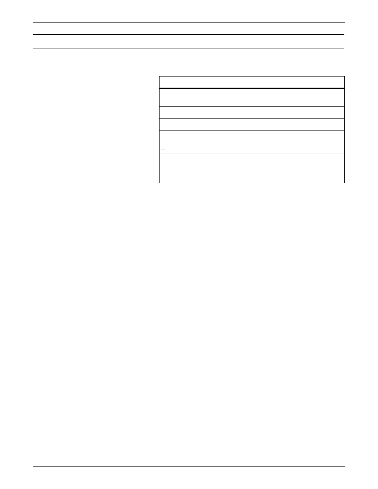
PDL syntax conventions used in this manual
Table 1 lists the syntax conventions and their usage.
Table 2. Syntax conventions
Syntax convention Explanation
inkref
or
dots
a | b | c Choices are separated by vertical bars.
{a | b | c} Required choices are enclosed in braces.
[a | b | c] Optional choices are enclosed in brackets.
INTRODUCTION
Variable names or values are represented
in italics.
b
Default options are underlined.
... (Ellipsis) indicates repetition of an
element, for example:
(
form-id
[,
form-id
1
][,...])
2
XEROX DOCUPRINT 96/DOCUPRINT 96MX LPS PDL REFERENCE xxv
Page 26

INTRODUCTION
xxvi XEROX DOCUPRINT 96/DOCUPRINT 96MX LPS PDL REFERENCE
Page 27

PDL features and functions
1. 1Overview
This chapter provides an overview of PDL related information you will
need in order to effectively utilize the PDL capabilities.
Print Description Language (PDL) is used to descr ibe printing jobs t o
a Xerox laser printing system (LPS). PDL accomplishes this by:
• Describing the input (type, format, characteristics)
• Describing the processing functions (logical processing)
• Describing the output (type, format, font selection, accounting
options).
Diverse application needs can be met because PDL enables you to:
• Change and mix font types on a page-to-page, line-to-line, or
character-to-character basis. Output can be customized for
specific needs, for example, highlighting important headings by
changing font styles and sizes.
• Change page orientation and positioning on a page-to-page
basis. Characters may be printed horizontally or vertically with
equal ease. The printing system switches instantly bet w een
horizontal and vertical page formats, combining the two styles
within a single report.
• Print a number of previously separate logical pages on the
same physical page of a document.
• Modify documents on a copy-to-copy basis by printing selected
portions of data on a page-to-page basis. You can replace
certain portions of text with other data, delete paragraphs from
some copies, or label other copies "confidential.
• Merge variable print data with forms stored on the system disk.
This eliminates the need for forms overlays and most preprinted
forms, as well as assuring perfect registration.
• Add data, position it on the page, and print it on a variety of
forms in one job. Multiple forms, stored in digital format, are
changeable on a page-to-page or copy-to-copy basis.
• Print two different forms back-to-back (duplex) on one sheet of
paper, therefore reducing paper costs. Additionally, this option
offers potential savings in inventory, filing, storage, and mailing
costs for computer-generated material.
• Feed paper either short-edge first or long-edge first to
accommodate a wide variety of paper sizes.
Before discussing PDL commands in detail, a general understanding
of LPS components and functions is helpful. The following sections
provide such a general overview.
XEROX DOCUPRINT 96/DOCUPRINT 96MX LPS PDL REFERENCE 1-1
Page 28

OVERVIEW
LPS component types
Hardware
Software
LPS components consist of hardware and software.
Hardware refers to all the physical components of the LPS.
Examples are the tape drives, the keyboard display, the highcapacity feeder-stacker, and the physical subsystems of the syst em
controller and the printer. Refer to your
DocuPrint 96MX LPS Operator Guide
hardware components of your LPS.
Software refers to all coded instructions (programs) which are
executed by the LPS. Some programs interface with LPS hardware,
some with LPS firmware, and some with other software. Examples
are the LPS operating system, the PDL compiler, and the output task.
Xerox DocuPrint 96/
for detailed descriptions of the
1-2 XEROX DOCUPRINT 96/DOCUPRINT 96MX LPS PDL REFERENCE
Page 29

LPS hardware components
Advanced Image Subsystem (AIS)
Step 1. In the first step, referred to as “fill”, the video forma t is stored into a
Step 2. In the second step, referred to as “dump”, the page buffer contents
OVERVIEW
The hardware components consist of the Advanced Image
Subsystem (AIS).
The Advanced Image Subsystem (AIS) consists of three printed wire
boards which contain character dispatcher, font and graphic
memory. The three boards read the character and image data and
convert it into video format for printing. With AIS, imaging a page is a
two-stage process performed by the hardware/firmware
combination:
64-megabit memory called a ”page buffer.” The entire page is
processed and stored into this memory resulting in a bitmapped
image.
are sent, one scan line at a time, to the laser.
Two page buffers enable one page’s video to be ”filled“ into one
buffer at the same time that the previous page’s video is being
”dumped” from the other page buffer.
XEROX DOCUPRINT 96/DOCUPRINT 96MX LPS PDL REFERENCE 1-3
Page 30

OVERVIEW
LPS software componen ts
The LPS operating system software (OSS), housed in the system
controller, runs both background and foreground processing. The
major programs or “tasks” run by the system controller are shown in
their hierarchical relationships in the list below. The OSS tasks are:
• Operating system executive (OSEXEC ) task
• File control program (FCP)
• Operator communication subsystem (OC S)
• Diagnostic tasks
• System util it ie s
• Editor task
• Font editor task
• Input processing task
• Ink catalog search (ICS)
• File transfer (XFR)
• Report processing (RPT)
• Memory control program (MCP)
• Termin al a nc illary contro l program (TACP)
• Ancillary IOT monitor program (AIM)
• Dynamic job descriptor (DJD) task
• Interpress decomposer (IPD) task
• Output processing task
• Print description language (PDL) processor
• Forms description language (FDL) processor
• Host interface processor (HIP) task.
1-4 XEROX DOCUPRINT 96/DOCUPRINT 96MX LPS PDL REFERENCE
Page 31

Figure 1-1 shows the relationships between these operating system
software tasks which load or invoke LPS operations.
Figure 1 -1. Major LPS processing tasks
Operating Syste m Exe cuti ve (O SEXE C)
File Control Program (FCP)
Operator Communication Subsystem (OCS)
OVERVIEW
Utilities
Editor
Diagnostics Font Editor
Host Interface Processor (HIP)
FDL Processor
PDL Processor Output
Input
DJD IPD
RPT
XEROX DOCUPRINT 96/DOCUPRINT 96MX LPS PDL REFERENCE 1-5
Page 32

OVERVIEW
PDL related programs and tasks
This section lists the programs and tasks most important to PDL.
Operating system executive task (OSEXEC)
The operat ing system executi ve (OSEXEC) task is always runni ng. It
interfaces with the LPS hardware and logs hardware errors. In
addition, it queues devices, manages resources, establishes priority
for software tasks, and schedules processing.
File control program (FCP)
The file control program (FCP) manages disk resources. It manages
and allocates all disk space, creates all disk files, and accesses disk
files.
Operator communication subsystem (OCS)
The operator communication subsystem (OCS) task acts as an
interface between the operator and software tasks. OCS receives
input from the operator and displays messages to the operator. OCS
also interfaces between system tasks.
Editor task
The editor task creates and modifies disk files. It uses a temporary
work file and stores the contents of the work file permanently on disk
when you save the file. It sends files to print and directs CMD files to
execute.
Font editor ta sk
The font editor task creates and modifies font files and allows you to
tailor fonts within a font file to meet the needs of each print job.
Input processing task
The input processing task reads in job parameters (JDL file), creates
a job control block, reads data, and handles job messages to the
operator. Then the input processing task does the following:
• Unpacks and converts the data
• Selects and deletes bloc ks or record s
• Records any special processing instructions (for page offsets,
DJDE records, CMEs).
1-6 XEROX DOCUPRINT 96/DOCUPRINT 96MX LPS PDL REFERENCE
Page 33

Report task (RPT)
Dynamic job descriptor (DJD) task
Output processing task
OVERVIEW
The report task works in connection with the input task. It records the
disk addresses of the font, form, and image files to be used for the
job. The result is a page buffer and a page log for each page to be
printed. The page buffer consists of the variable data and print
instructions for the page. The page log consists of tracking
information used in processing the page.
The dynamic job descriptor (DJD) task compiles the dynamic job
descriptor entries (DJDE) in the input data stream. The DJDEs give
the LPS instructions for printing based on IDEN command parameter
specifications in the input data stream.
The output processing task uses the page logs written by the input
task to load fonts, graphics, and variable data in the Advanced Image
Subsystem (AIS). It coordinates the activity of the AIS with the
printer. In addition, output manages delivery of the printed pages to
the correct bins, performs page recovery if necessary, and performs
accounting functions.
Print description language (PDL) processor
The PDL compiler compiles an ASCII job source language (JSL) file
into object code and saves it as a job descriptor library (JDL) file. It
also creates ancillary files like PDE, CME, STK, LIB, e tc.
Forms description language (FDL) processor
The FDL compiler compiles an ASCII form source language (FSL)
file into executable object code and saves it as an (FRM) form file.
XEROX DOCUPRINT 96/DOCUPRINT 96MX LPS PDL REFERENCE 1-7
Page 34

OVERVIEW
Preparing for a print job
Before a print job runs, the system administrator, programmer,
operator, and LPS work together:
• System administrator loads fonts, logos, and signatures to the
printer from tape, floppy, or the host. Refer to the
DocuPrint 96/DocuPrint 96MX LPS Operations Reference
detailed information.
Xerox
for
• System administrator determines the fonts, forms, and graphics
system parameters needed by the job.
• Programmer creates the JSL and FSL source files.
• Programmer invokes the FDL compiler to compile the FSL files
into form ( FR M ) files fo r t he p ri nt job.
• Programmer invokes the PDL compiler to compile the source
files into CME, TST, PDE, JDL, LIB, and STK object files for the
print job.
• Operator resets the syst em paramete r s to match th e font s,
forms, and graphic requirements of the job.
• LPS completes any foreground processing and waits in IDLE
status for the operator to enter the START command with the
JDE and JDL for the print job.
1-8 XEROX DOCUPRINT 96/DOCUPRINT 96MX LPS PDL REFERENCE
Page 35

Job flow process
OCS processing
OVERVIEW
The job flow process consists of OCS processing, Input processing,
and Output processing.
The steps required during OCS processing are summarized below.
Step 1. The START comm and ident ifies the JDE/JDL c reated by the
programmer for the job. The OCS task reads the START command
and notifies the OSEXEC task to load output, input, DJD, and IPD
tasks.
Step 2. The OC S task then writes a job queue entry (JQE) for the job in the
job queue buffer. The JQE includes information from the start
command, for example, the JDE and JDL name and the number of
copies.
Input processing
The steps required during Input processing are summarized below.
Step 1. The RPT task first initializes the job queue buffer from the start JDE/
JDL information by recording job characteristics such as block
length, fonts needed, and required forms.
Step 2. The input task finds the disk addresses of the compiled JDE, form,
font, and logo files to be used in printing the variable data.
Step 3. If the print job is in Interpress format, the IPD converts the data to
ASCII format for the input task.
Step 4. The input task reads the variable data.
Step 5. The input task formats the variable data and writes it to the data
buffer in the print file PRFIL1.SYS. For each page in the data buffer,
the input task creates a page log entry in the page log buffer and
writes the buffer to the PRFIL1.SYS file.
Step 6. When the input task processes all the data, or reaches page
threshold (uses a certain portion of the area reserved for the
PRFIL1.SYS file), it notifies the OCS task that the output task can
begin.
XEROX DOCUPRINT 96/DOCUPRINT 96MX LPS PDL REFERENCE 1-9
Page 36

OVERVIEW
Output processing
The steps required during Output processing are summarized below.
Step 1. The OC S task sends a message to output indicating that output
processing can start. This message includes the address in the
PRFIL1.SYS file of the information for the first page to be printed.
Step 2. The output task reads the starting page log buffer and builds an entry
in its own page tracking buffer. The page tracking buffer contains the
information output processing uses for page creation (text, data,
form, and font addresses, counts, and flags for options such as
simplex or duplex).
Step 3. The output task copies portions of the font, graphic, and logo files
from disk to the Advanced Image Subsystem (AIS). The AIS is
instructed to create the page image from these specifications and
store it in its private page buffer.
Step 4. The output task instructs the AIS to send the page image to the
printer. As the AIS sends the image, the output task uses the page
tracking buffer to monitor and record delivery of the printed page to
the bin.
Step 5. The output task identifies each page successfully printed and
delivered. The input task can then reuse that page space in the page
buffer to process an incoming page.
The output task also identifies each page unsuccessfully printed or
delivered. The output task uses the page buffer and log information
stored in the PRFI L1.SYS file to repeat the steps which recreate the
page image, send it to the printer, and monitor its delivery to the bin.
Then the output task releases the space for that page in the
PRFIL1. SYS file.
Step 6. When the output task has verified the successful printing and delivery
of all pages prepared for it by the input task, the output task signals
the input task that output processing is waiting for more formatted
page and page log buffers.
Step 7. When the input task reaches the end of file marker on the input data,
the input task messages the OCS task that input processing of the
print job is complete.
Step 8. The OC S task displays the JOB XXXX HAS COMPLE TED INPUT
PHASE. message to the operator.
Step 9. When the output task finishes printing, it messages the OCS task that
the job has completed printing.
Step 10. The OCS task displays the following mes sage to the operator:
JOB XXX HAS COMPLETED PRINTING.
1-10 XEROX DOCUPRINT 96/DOCUPRINT 96MX LPS PDL REFERENCE
Page 37

Input data types
Unformatted data
OVERVIEW
The LPS can work effectively in many different environments, and it
has the capability to handle input from a wide variety of sources.
Whether you are using the LPS in an offline capacity, over an
Ethernet network, connected directly to a host computer, or remotely
over phone lines, input data for printing is sent to the printer in one of
two forms:
• Unformatted
• Formatted.
Unformatted data—that is, raw data from a computer file—is
selected, formatted, and combined with form data (boxes, lines,
headings, totals, and so forth) and graphics files to produce a printed
report.
• The raw data can be sent to the LPS offline from magnetic tape,
online from a channel-attached host, or through an Ethernet
network.
• The forms definition commands used to select records and
format the printed output can be entered directly from the
keyboard display, or from a host- or PC-based forms definition
software package.
If you are using the LPS to create reports or other documents from
unformatted data, several elements are required to complete the job:
• Variable data. Variable data is the part of the report that
changes from page to page. In the example of an inventory
report, the variable data would be the part numbers,
descriptions, prices, costs, and so forth.
The variable data can be input from the magnetic tape system
in the offline mode, from a host through a channel interface,
through an Ethernet network interface, or from a remote host
over phone lines.
• Form data. Form data can include headings, boxes, lines, and
graphic image files, such as signatures or logos. Form data is
entered in the form of compiled files, comprised of JDL and FDL
statements entered through the LPS editor in the offline mode,
or in the online mode through one of several host-resident
forms design packages.
XEROX DOCUPRINT 96/DOCUPRINT 96MX LPS PDL REFERENCE 1-11
Page 38

OVERVIEW
• Processing data. Pr ocessing data is optional and it allows the
operator to control the output of selected reports, or selected
copies of a multiple copy report, for cover-to-cover print
processing on any job. For example, you may wish to specify
that an inventory report has a blue card stock cover, 49 pages
of the report, and a blue card stock back cover. You may also
decide that four copies without cost information are needed for
distribution to clients. The three command sets described below
provide output control:
— JDE. Gives the operator control over the mechanics of a
particular print job. JDE commands specify the feed and
output trays, simplex or duplex printing, stapling, collating,
and so forth.
— DJDE. Enables you to modify the printing environment
dynamically. These commands are inserted into the input
data stream to modify the command characteristics of the
existing job descriptor entry (JDE). DJDEs can take effect
on a report-to-report, page-to-page, and record-to-record
basis.
— CME. Enables you to replace certain parts of a report with
predefined static data on selected copies or to specify font
changes within the variable data.
Formatted data
Page description and report data from host-resident software is sent
to the LPS in a form that it understands; therefore, no additional
formatting commands are required.
Many such host-resident software packages communicate with the
LPS in page description languages.
Formatted data is sent to the LPS from a host-based document
composition software package, for example, XPPI, XDGI , or PCbased software through the front-end processor. These systems are
often used for electronic publishing and can produce very
sophisticated printed documents. Data from these sources come in a
form that the Xerox DocuPrint 96/DocuPrint 96MX LPS can already
understand; there is no need for the operator to create forms
definition files or the like, as it is with the unformatted data described
above.
1-12 XEROX DOCUPRINT 96/DOCUPRINT 96MX LPS PDL REFERENCE
Page 39

Purpose of PDL
2. 2Print Description Language
(PDL)
This chapter discusses the following PDL topics used to create and
control print jobs.
• Purpose of PDL
• PDL command structure
• JSL structure
• Creating separate command files
• Hierarchy of replacement
For a job to be printed on an LPS, it is necessary to create a file of
PDL commands to define the format of the input media, processing
requirements, and the format of the printed output. The source or
uncompiled file of PDL commands is referred to as a job source
library (JSL) file. All JSL files must be compiled before they can be
referenced to print a job. The object or compiled file of a job source
library file is referred to as a job descriptor library (JDL).
This compilation process is depicted in figure 2-1.
Figure 2 -1. PDL compilation
Each command has a set of parameters that can be used to define
the characteristics of a print job (input, special processing, output).
PDL commands used in creating a JSL may be entered at:
• Host, using a host-based editing facility to create 80 byte
EBCDIC records.
• LPS system controller. Refer to the
DocuPrint 96MX LPS Operations Reference
Xerox DocuPrint 96/
.
XEROX DOCUPRINT 96/DOCUPRINT 96MX LPS PDL REFERENCE 2-1
Page 40

PRINT DESCRIPTION LANGUAGE (PDL)
PDL command structure
Command line length
The primary element of a JSL is a job. A job, which is one printing
task, is referred to as a job descriptor entry (JDE). (In PDL, t he terms
“job” and “JDE” are used interchangeably.) It usually defines one
input format, one set of processing instructions, and one set of output
instructions. Each job has a user-defined name that you invoke to run
the job.
To produce a finished job or application, a JSL must be created and
then compiled into a JDL file. To accomplish this, you must use PDL
commands and be knowledgeable about PDL co mmand s tructure,
which includes the following topics:
• Command line length
• Command components
• Right-part constants
Table 2-1 illustrates a set of typical PDL commands. PDL commands
consist of command lines, also called records, whose length can be
up to 133 characters for JSLs on tape, of which only characters 1-72
may be used for parameter information. Command lengths less than
72 characters are acceptable. Each PDL command consists of a
command keyword and one or more parameters separated by
commas or spaces. Spaces are also permitted around the equal sign
(=).
Command components
Commands may be continued on successive records if parameters
are separated by commas. Crossover is performed from one record
to the next when column 73 is reached or when the end-of-record is
reached for records of fewer than 72 characters. Multiple commands
may appear on one record if separated by semicolons.
The components of a PDL command are:
• Command identifier, if required
• Command keyword
• One or more command parameters
• Parameter options
• Comments, if appropriate
These are shown in figure 2-2.
2-2 XEROX DOCUPRINT 96/DOCUPRINT 96MX LPS PDL REFERENCE
Page 41

Identifier
PRINT DESCRIPTION LANGUAGE (PDL)
In addition, there are syntax rules you must use in order for the
system to recognize and process your JSLs. These rules are
described later in this section.
Figure 2 -2. Example of PDL command components
In this example, the identifier, parameter keyword, and parameter
options are all part of the VFU command, which is represented by
VFU, the required command keyword. All of these components may
be collectively referred to as a command statement.
Command keyword
If the command is to be referenced by another command, an
identifier must precede the command keyword.
The PDL command below has a command identifier (VFU1), a
command keyword (VFU), and three command parameters
(ASSIGN, TOF, BO F) :
VFU1: VFU ASSIGN=(1,1),TOF=1,BOF=55;
END;
A command identifier is a label that may consist of one to six
alphanumeric characters (A-Z and 0-9). It must be followed by a
colon (:). The identifier VFU1 in the command above could be coded
with any number of blanks following the VFU1 characters, but can
have no blanks within the identifier name.
Note: The VFU1 identifier is referenced in the LINE command
(LINE VFU=VFU1) of tables 2-1 and 2-2. A command that requires
an identifier must always be defined prior to any reference to it.
A command keyword is required. For example, CME is the command
keyword in table 2-1 and VFU, TABLE, CRITERIA, CME, PDE, and
so on are the command keywords in table 2-2. A command keyword
is required for each PDL command statement. All command
keywords are listed in appendix A.
XEROX DOCUPRINT 96/DOCUPRINT 96MX LPS PDL REFERENCE 2-3
Page 42

PRINT DESCRIPTION LANGUAGE (PDL)
Parameter
Each command keyword is followed by parameters used to select its
processing parameters. The parameters for a PDL command
keyword consist of a left and right part separated by an equal sign
(=).
Table 2-1 represents the typical components of a command
statement and provides examples.
Table 2-1. Set of typical PDL commands
Comments
Identifier
VFU1:
CME4:
Command
keyword
(required)
VFU
CME
Parameter
keyword
ASSIGN=
LINE =
Parameter
option
(1,1),
(1,60),
Additional
parameter
keywords
TOF=1,BOF=55;
POSITION=5,
FONT=2;
Comments are statements you include in the source file to describe
certain PDL commands and their functions. These comments can act
as reminders if you, or someone else modifies the JSL at a later time.
Comments may appear anywhere within the JSL. They must be
preceded by the character sequence slash and asterisk (/*), and
terminated by the character sequence asterisk and slash (*/).
Examples are illustrated in figures 2-3, 2-4, and 2-5. Nested
comments may be set within another comment. There is no practical
limit to the level of nesting possible, as long as each nested comment
is preceded by a slash and an asterisk (/*) and succeeded by an
asterisk and a slash (*/). An acceptable nested comment format is as
follows:
/*comment
/*nested comment*/
*/
2-4 XEROX DOCUPRINT 96/DOCUPRINT 96MX LPS PDL REFERENCE
Page 43

Syntax rules
PRINT DESCRIPTION LANGUAGE (PDL)
When entering your JSL records on the system controller keyboard,
make sure to follow these rules:
• Use commas or blanks to separate the individual left- and right-
part parameters of a command.
• Use parentheses to enclose multiple right parts.
• List parameter options in the sequence shown in this manual.
To specify a particular option but not the options preceding it,
use commas or blanks as “place holders” for the options you do
not specify. For example, the OUTPUT command BFORM
parameter has three options:
BFORM=(
To specify the form name (form-id) and number of copies, but
not the initial cop y (init) o n which the backsi de form (BFORM) is
printed, enter:
BFOR M=(SMLFRM,,2)
The second comma (,) after SMLFRM tells the system that “2”
specifies the number of copies on which the form is printed.
form-id,[init
][,
copies
])
• Use blanks anywhere in the JSL except in keywords and
constants.
• Abbreviate command and parameter keywords to the first three
letters, for example, POSITION or POS, OUTPUT or OUT. The
only exception is FOR, which the system interprets as the
parameter FORMAT instead of FORM. Therefore, make sure to
use the abbreviation FOR to represent FORMAT only, or avoid
the abbreviation entirely to prevent errors.
• Use a semicolon (;) to indicate the end of an element of data for
the system. It must be at the end of every PDL command.
• Enter command parameters such as FONT, FORM, and
GRAPHIC in their singular form as shown, or with an optional
plural “s,” such as FONTS, FORMS, and GRAPHICS.
• Enter the END command to signal the end of a JSL. You may
then enter another JSL into the system if you wish. Use two
END; commands to signal the end of all JSLs to be processed:
END; END;
Example LINE VFU=VFU1, DATA=(1,10),
OVERPRINT=(PRINT,DISP);
This LINE command example contains three left-part command
parameters, VFU, DATA, and OVERPRINT, a right-part reference to
an identifier, VFU1, and parameter options (1,10) and (PRINT,DISP).
XEROX DOCUPRINT 96/DOCUPRINT 96MX LPS PDL REFERENCE 2-5
Page 44

PRINT DESCRIPTION LANGUAGE (PDL)
Right-part constants
Value constants
String constants
Constants within the right part of a left/right-part parameter may be
either value or string constants. The syntax of these constants is
defined below.
Value constants are constants that have arithmetic values. They
should be expressed as decimal numbers. They may be expressed
as hexadecimal values, octal values, or even character values, but
these expressions are not recommended. Decimal constants may be
signed and in some cases may have fractional digits, for example:
PDE BEGIN=(1.1, .37);
BLOCK LENGTH=1320;
RECORD LENGTH=132;
IMAGE=(1.30 CM, 0.85 IN);
String constants are normally used to specify strings of characters or
to reference identifier parameters. The length of string constants is
important. String constants may be expressed as any of the
following:
• Keyword
• Variable name
• Hexadecimal
• Character
• ASCII
• EBCDIC
• Octal
• H2 or H6
Keyword Keywords are terms that direct the system to perform specific
predetermined activities. Keywords always consist of the same
characters and do not vary. For example:
BLOCK ZERO=YES;
ABNORMAL ERROR=CONTINUE,
OTEXT=WAIT;
ACCT USER=BOTH;
Variable name String constants may be used to specify names of forms, files, fonts,
departments, and so on. In creating your JSLs, you assign names to
the forms and files you want to specify. Each name you assign
identifies the unique object you wish the syst em to act upon for your
applications. For example:
OUTPUT FORM=SMPLE,
BFORM=SMPBK,
FEED=BLUCVR,
MODIFY=CME12;
2-6 XEROX DOCUPRINT 96/DOCUPRINT 96MX LPS PDL REFERENCE
Page 45

PRINT DESCRIPTION LANGUAGE (PDL)
Hexadecimal Normally used as string constants, but they may also be used as
value constants. Each pair of hexadecimal characters results in one
byte. A hexadecimal constant must immediately be preceded by the
characters X apostrophe (X) to indicate to the PDL compiler that the
following expression is in hexadecimal. For example:
IDEN PREFIX=X’C1C2C3C4’;
Character Normally used as string constants, but they may also be numeric
value constants. Each character, including embedded blanks, results
in one byte. A character constant must immediately be preceded and
immediately followed by the apostrophe (’) character. For example:
IDEN PREFIX=’THIS IS A CHARACTER CONSTANT’;
CONSTANT=’ABCDE’;
If the apostrophe character ’(’)’ is required in a character constant, it
must be defined in some other way, such as consecutive or double
apostrophes ("), or the hexadecimal constant X’7D’. Character
constants may be defined as EBCDIC and take their actual values
from the standard EBCDIC table definition in appendix D.
ASCII Us ed as string constants. Each character results in one byte. The
constants must be preceded by the characters A apostrophe (A) and
followed by an apostrophe character. For example:
IDEN PREFIX=A'ABC';
The ASCII string type allows hexadecimal representation of
characters to be embedded in a string. This is done by preceding the
hexadecimal representation of the character with an ! character. For
example:
IDEN PREFIX=A’ABC!44EF’
is equivalent to
IDEN PREFIX=X’414243444546’
The three-character sequence required for a hexadecimal
representation of a character results in one byte.
Two successive ! characters (!!) are necessary to represent one
actual ! character when printing. The two-character sequence (!!)
results in one byte.
XEROX DOCUPRINT 96/DOCUPRINT 96MX LPS PDL REFERENCE 2-7
Page 46

PRINT DESCRIPTION LANGUAGE (PDL)
EBCDIC EBCDIC constants are used for value and string constants. They
must be preceded by the characters E apostrophe (E) and followed
by an apostrophe character (’). The EBCDIC string type allows
hexadecimal representation of characters to be embedded in a
character string. This is done by preceding the hexadecimal
representation of the character with an ! character.
For example:
IDEN PREFIX=E’ABC!C4EFG’
is equivalent to the hexadecimal
IDEN PREFIX=X’C1C2C3C4C5C6C7’
Each character represented in EBCDIC results in one byte. Each
three-character sequence representing a character hexadecimally
results in one byte.
Note that EBCDIC is the default, therefore the E 'xxx' is usually not
required.
Octal Octal constants should be used only as string constants because of
the control program conversion process. Each octal character results
in 3 bits. One word can store 3 characters. Their use as value
constants, however, is not prohibited. Each 3-bit octal character is
converted to an 8-bit octal character, internally, by prefixing two
binary zeros. Thus, the arithmetic value of a multiple-character octal
constant may be difficult to determine because each digit in the
constant has been altered. An octal constant must be preceded
immediately by the characters letter O apostrophe (O) and
immediately followed by the apostrophe (’) character. For example:
BLOCK CONSTANT=O’07070707’
H2 and H6 H2 and H6 constants generate H2000 BCD and H6000 BCD codes,
respectively. Use of H2 and H6 is identical to use of E and A prefixes
described above. For example:
BLOCK CONSTANT=H2’373737’
BLOCK CONSTANT=H6’373737’
Since H2000 and H6000 BCD are defined as 6-bit codes (refer to
appendix C), no specification greater than X'3F' generates a legal
character. If anything from X'40' to X'FF' is coded, PDL generates an
error message and replaces the bad character with a blank.
String constants may be preceded by an optional repeat count. A
repeat count is enclosed in parentheses and must be in the range of
1 to 255. For example, the command:
T1: TABLE CONSTANT=(3)’*’;
is equivalent to:
T1: TABLE CONSTANT=(’***’);
Other examples of the use of a repeat count are:
T1: TABLE CONSTANT=(3)O’27’;
T2: TABLE CONSTANT=(4)X’C1’;
2-8 XEROX DOCUPRINT 96/DOCUPRINT 96MX LPS PDL REFERENCE
Page 47

PRINT DESCRIPTION LANGUAGE (PDL)
Table 2-2 represents a JSL which includes the components of PDL
commands and shows a variety of right-part constants.
Table 2-2. Sample PDL commands
Identifier
Command
keyword
Parameter keyword followed by parameter options and
additional parameter keywords
VFU1: VFU ASSIGN=(1,1),TOF=1,BOF=55;
VFU2: VFU ASSIGN=(1,(4,59)),TOF=4,BOF=127;
T1: TABLE CONSTANT=(’C#LIPS’);
C1: CRITERIA CONSTANT=(14,5,EQ,T1),LINENUM=(6,3);
T2: TABLE CONSTANT=(’1’);
C2: CRITERIA CONSTANT=(0,1,NE,T2);
CME1: CME LINE=3,POS=59,CONSTANT=’FIRST QUARTER’;
CME4: CME LINE=(1,60),POSITION=5 FONT=2;
PDE2: PDE PMODE=PORTRAIT, BEGIN=(1.1,.37),
FONTS=(P08TYA, P08SCA);
CODTAB: CODE DEFAULT=EBCDIC, ASSIGN=(X’4A’,X’B4’);
VOLUME LABEL=NONE, HOST=IBMOS, CODE=CODTAB;
BLOCK LENGTH=1320;
RECORD STRUCTURE=FB,LENGTH=132;
LINE VFU=VFU1,DATA=(1,10),OVERPRINT=(PRINT,DISP);
ACCT USER=BIN, DEPT=’MEDCAR’;
OUTPUT FORMS=XER111,FORMAT=PDE2,MODIFY=CME4;
ROUTE RTEXT=(’ENGINEERING’,2,56,109),RFORM=XERCOV;
RDELETE TEST=(C1,AND,C2);
IDEN PREFIX=’$DJDE’,SKIP=10,OFFSET=1;
XEROX DOCUPRINT 96/DOCUPRINT 96MX LPS PDL REFERENCE 2-9
Page 48

PRINT DESCRIPTION LANGUAGE (PDL)
Job source library (JSL) structure
To simplify JSL coding, PDL commands are grouped into command
levels. The use and syntax of command levels, along with the
required END command, are defined in the following sections:
• ID level
• System level
• Catalog level
• Job or JDL level
• END command
The command levels are always preceded by the JDL coding, which
provides the name of the compiled JDL.
Command levels
You can place PDL commands in any command level, depending on
your particular application needs.
Table 2-3 outlines the command levels and some typical
specifications that are included in these various levels.
Table 2-3. Command levels and their general purpos e
Command
level General purpose
ID Typically used to assign output channel numbers to
printer carriage control channels through the VFU
command, but any command which has an identifier
may be used at the ID level, such as the CODE,
PCC, and ROUTE commands.
System or
JDL
Catalog Groups PDL commands for easy reference at the job
Job or JDE Def ines how individual print jobs are processed.
Establishes installation defaults.
level.
2-10 XEROX DOCUPRINT 96/DOCUPRINT 96MX LPS PDL REFERENCE
Page 49

PRINT DESCRIPTION LANGUAGE (PDL)
Figure 2-3 illustrates a sample JSL file format and provides
examples.
Figure 2 -3. Sample JSL file format
JDLSMP:
VFU1:
VFU9:
CAT1:
JOBCPP:
JOB2:
JOB3:
JDL;
/* THIS SAMPLE JSL SHOWS THE JSL COMMAND LEVELS*/
/* ID LEVEL COMMANDS CODED HERE*/
VFU ASSIGN = (1,1), TOF = 1, BOF = 66;
VFU ASSIGN = (1,9), TOF = 9, BOF = 66;
/* SYSTEM LEVEL COMMANDS CODED HERE*/
VOLUME HOST = IBMOS;
BLOCK LENGTH = 1330;
RECORD LENGTH = 133;
LINE VFU = VFU9, DATA = (1,132);
OUTPUT FORMS = CPPR1, DUPLEX = NO,
COPIES = 2;
/* CATALOG LEVEL COMMANDS CODED HERE IF NEEDED*/
CATALOG;
LINE VFU = VFU1;
OUTPUT FORMS = FORM2;
/* JOB LEVEL COMMANDS CODED HERE*/
JOB;
JOB INCLUDE = CAT1;
JOB INCLUDE = CAT1;
OUTPUT DUPLEX = YES;
END;
XEROX DOCUPRINT 96/DOCUPRINT 96MX LPS PDL REFERENCE 2-11
Page 50

PRINT DESCRIPTION LANGUAGE (PDL)
ID level
System or JDL level
The ID level has commands that require identifiers so that they can
be referenced by other commands in lower command levels. For
example, the ID level contains one or more VFU commands, as
shown in table 2-2. As with the other command levels any PDL
command can be specified at the ID level. The ID level must be
preceded by JDL coding, which names the JSL. For example:
XSML: JDL;
VFU1: VFU ASSIGN=(1,1),TOF=1,BOF=66;
In this example, XSML:JDL is the name of the complete JDL and the
VFU command is in the ID level.
A system or JDL command set establishes installation-dependent
requirements and default values for job descriptor entries. At the
system level, JDL may be used interchangeably with SYSTEM. At
the system level, commands are specified which apply to all job
descriptor entries (JDEs) identified within a job descriptor library
(JSL). Each SYSTEM command results in the creation of a JDL when
compiled.
Catalog level
The SYSTEM command has the form:
jdl-name
jdl-name
{SYSTEM JDL;}
is a 1 to 6 character alphanumeric identifier specifying the
name of the JDL to be created. It must contain at least one alphabetic
character.
For example:
SAMPL: SYSTEM;
This command identifies the start of a SYSTEM command and the
beginning of a JDL. The jdl-name SAMPL corresponds to the name
of the JDL to be used when printing a job. When DFAULT is coded
for the jdl-name, the specification of a JDL parameter option in the
START command is not necessary.
The catalog level allows the coding of commands common to several
JDE s. A cat al og c an t he n be ref er enc ed i n a n IN CLU DE c om man d in
each JDE. A catalog command level is identified by the CATALOG
command and ends with the appearance of another CATALOG
command or a JOB command. CATALOG co mmands m ay contain
the same commands which appear in the JOB command.
The CATALOG command has the form:
cat-name
: CATALOG;
cat-name
is a 1 to 6 character alphanumeric identifier of which at
least one character must be alphabetic. The cat-name is referenced
by JDEs after the CATALOG command set has been defined.
For example:
POWER:CATALOG;
2-12 XEROX DOCUPRINT 96/DOCUPRINT 96MX LPS PDL REFERENCE
Page 51

Job or JDE level
PRINT DESCRIPTION LANGUAGE (PDL)
In this command, POWER is the catalog level identifier to be used in
the INCLUDE parameter of a JOB command.
For example, to reference the catalog named POWER in a job, the
job level command would be:
JOB1:JDE INCLUDE=POWER;
The job or JDE level allows the grouping of individual jobs together.
PDL commands coded within the job command level override the
system commands. PDL commands from a catalog comm and level
can be incorporated as shown in the command syntax below. For
each job, values not specified in any of the command sets are taken
from the PDL defaults as defined in appendix A. The JOB or JDE
command has the following form:
jdl-name
jde-name
name of the JDE being defined.
cat-name
of a previously defined catalog name.
Examples–JOB command
JOB2: JDE;
JOB3: JOB
INCLUDE=POWER;
JOB4: JDE;
LINE VFU=VFU2;
OUTPUT FORMS=AY2F;
A JOB command continues until another JOB, JDE comma nd or
END command is encountered. The catalog identifier in a JOB or
JDE command as with JOB3 above, JOB2 is used along with the
identifier on the SYSTEM command set to initiate a print job. When
DFLT is coded for the jde-name, the specification of a JDE parameter
option on the START command is not necessary.
END command
A JDL terminates with the END command. If one JDL is to follow
another, the next command after the END command should be
another SYSTEM command.
: {JOB JDE} [INCLUDE = (
cat-name
[,
cat-name
1
][,...])];
2
is a 1 to 6 character alphanumeric identifier. It specifies the
or
cat-name-n
is a 1 to 6 character alphanumeric identifier
The end of all JDLs to be processed is indicated by two consecutive
END commands:
END; END;
Figures 2-4 and 2-5 provide examples of offline and online JDLs.
In figure 2-4, note that HOST=POWERVS indicates the source and
structure of input data. The HOST command indicates whether the
JSL is for an offline or online job. Some HOST parameters can apply
to both online and offline hosts. Refer to appendix A for a quick
reference.
XEROX DOCUPRINT 96/DOCUPRINT 96MX LPS PDL REFERENCE 2-13
Page 52

PRINT DESCRIPTION LANGUAGE (PDL)
Figure 2 -4. Sample offline job descriptor library
IBMPDL: SYSTEM; JDL coding
/*THIS JOB DESCRIPTOR LIBRARY CONTAINS JOB DESCRIPTOR ENTRIES FOR
PROCESSING GRASP, POWER AND POWER VS JOB TAPES
THE SYSTEM STATEMENT SET DEFINES CONSTANTS AND PROCESSING PROCEDURES
THAT WILL APPLY TO ALL JOBS PROCESSED USING THIS LIBRARY UNLESS
OVERRIDDEN BY THE CATALOG OR JOB COMMAND SETS */
VFU001: VFU ASSIGN=(1,5),ASSIGN=(2,10),ASSIGN=(3,15)
ASSIGN=(4,20),ASSIGN=(5,25),ASSIGN=(6,30),
ASSIGN=(7,35),ASSIGN=(8,40),ASSIGN=(9,45), ID level
ASSIGN=(10,50),ASSIGN=(11,55),ASSIGN=(12,60),
TOF=5,BOF=66;
VOLUME HOST=POWERVS,PLABEL=YES,CODE=ASCII;
BLOCK LENGTH=2048;
RECORD LENGTH=136,STRUCTURE=VB,LTHFLD=2,
ADJUST=0,FORMAT=BIN,PREAMBLE=3;
LINE DATA=(1,132),PCCTYPE=IBM1403,PCC=(0,NOTRAN), System
OVERPRINT=(PRINT,NODISP),VFU=VFU001; level
ACCT USER=(BIN,TRAY);
/* CATALOG COMMAND SET FOR POWER VERSIONS */
CATPOW: CATALOG;
VOLUME HOST=POWER,CODE=EBCDIC;
BLOCK LENGTH=2048,PREAMBLE=6,LTHFLD=2,FORMAT=BIN,
OFFSET=4;
RECORD LENGTH=135,STRUCTURE=VB,PREAMBLE=2,LTHFLD=2,
FORMAT=BIN,OFFSET=0,ADJUST=3;
/* CATALOG COMMAND SET FOR GRASP */
CATGRP: CATALOG; Catalog
VOLUME HOST=GRASP,CODE=EBCDIC; level
BLOCK LENGTH=4096,PREAMBLE=0,ZERO=YES;
RECORD LENGTH=135,STRUCTURE=VB,PREAMBLE=1,
LTHFLD=1,FORMAT=BIN,OFFSET=0,ADJUST=2;
/* THE FOLLOWING JDES ARE FOR IBM POWER GRASP VS TAPES,
POWER VERSION 4.0 TAPES */
1:JOB;
VOLUME HOST=POWERVS,CODE=PEBCDIC;
2:JOB; INCLUDE=(CATPOW);
VOLUME HOST=POWER;
RECORD LTHFLD=1,PREAMBLE=1,ADJUST=2;
3:JOB; INCLUDE=(CATPOW); Job
VOLUME=HOST=POWERVS,CODE=PEBCDIC level
4:JOB; INCLUDE=(CATGRP);
VOLUME HOST=POWER;
END;
In figure 2-5, note that online systems do not define the BLOCK
command.
2-14 XEROX DOCUPRINT 96/DOCUPRINT 96MX LPS PDL REFERENCE
Page 53

PRINT DESCRIPTION LANGUAGE (PDL)
Figure 2 -5. Sample online job descriptor library
ONLINE: JDL; JDL coding
VFU1: VFU ASSIGN=(1,4),ASSIGN=(2,10),ASSIGN=(3,16),
ASSIGN=(4,22),ASSIGN=(5,28),ASSIGN=(6,34),
ASSIGN=(7,40),ASSIGN=(8,46),ASSIGN=(9,66), ID level
ASSIGN=(10,52),ASSIGN=(11,58),ASSIGN=(12,64),
TOF=4,BOF=66;
VOLUME HOST=IBMONL,
OPTIMIZE=(NCC,NDC,NPR);
LINE PCCTYPE=IBM3211,VFU=VFU1,
UCSB=IGNORE,FCB=IGNORE;
ACCT USER=(BIN,TRAY);
IDEN PREFIX=’DJDE’,SKIP=7,OFFSET=2,OPRINFO=YES;
/* */
/* TABLES AND CRITERIA */
/* */
T1: TABLE MASK=’?’,CONSTANT=’HE?DE? PAGE’;
C1: CRITERIA CONSTANT=(1,11,EQ,T1),LINENUM=(1,10);
T2: TABLE CONSTANT=’TRAILER PAGE’; System
C2: CRITERIA CONSTANT=(0,12,EQ,T2),LINENUM=(1,10); level
T3: TABLE CONSTANT=’EOJ’;
C3: CRITERIA CONSTANT=(0,3,EQ,T3),
LINENUM=(1,20);
T4: TABLE CONSTANT=’// JOB’;
C4: CRITERIA CONSTANT=(0,6,EQ,T4),
LINENUM=(1,20);
T5: TABLE CONSTANT=(10)’*’;
C5: CRITERIA CONSTANT=(0,10,EQ,T5),
LINENUM=(50,10);
/* */
/* JOBS WITH NO BANNER PAGES */
DFLT: JOB;
/* */
/* JOBS WITH HEADER PAGES ONLY */
HDRP: JOB;
BANNER TEST=C1,HCOUNT=2,TCOUNT=0;
/* */
/* JOBS WITH TRAILER PAGES ONLY */
TRLP: JOB;
BANNER TEST=C2,HCOUNT=0,TCOUNT=3;
/* */
/* JOBS WITH BOTH HEADER AND TRAILER PAGES */ Job
BOTH: JOB; level
BANNER TEST=(C1 OR C2),HCOUNT=2,TCOUNT=3;
/* */
/* OTHER JOBS */
/* */
EOJ: JOB;
BANNER TEST=C3,TCOUNT=1;
JOB: JOB;
BANNER TEST=C4,HCOUNT=1;
POWER: JOB;
BANNER TEST=C5,HCOUNT=2;
/* */
END;
XEROX DOCUPRINT 96/DOCUPRINT 96MX LPS PDL REFERENCE 2-15
Page 54

PRINT DESCRIPTION LANGUAGE (PDL)
Creating separate files for grouping PDL commands
If you have multiple commands of the same type, such as CMEs and
PDEs, you may want to create separate files for them to group like
specifications together and to make your JSLs shorter and more
efficient. You can create these types of command files by simply
listing them as you would in a JSL and complete the list with an END;
command before specifying a JSL’s JDL coding identifier instead of
after it.
Files containing groups of PDE and CME commands may be created
as system or editor files. Because you use the editor to create and
modify your JSLs, it may be more efficient for you to create these
command files in the editor.
Hierarchy o f replacement
Refer to your
Reference
command files.
The system default values shown in appendix A are the more
commonly used values in job processing; they can be thought of as
a basic job descriptor entry (JDE). PDL commands need coding for
only those parameters that must be changed to process your unique
print jobs. This coding process may be further specified by placing
commands common to more than one job in the catalog command
level. When these coding features are properly implemented, it is
possible for the same command to be used in more than one job or
JDE command level within a library. The PDL processor evaluates
user coded commands and applies the highest order, error-free
definition to the job for printing. This process, termed the hierarchy of
replacement, is discussed in the subsequent paragraphs and
illustrated in figure 2-6.
Xerox DocuPrint 96/DocuPrint 96MX LPS Operations
for detailed information on using system and editor
2-16 XEROX DOCUPRINT 96/DOCUPRINT 96MX LPS PDL REFERENCE
Page 55

Hierarchy within a job descriptor library (JDL)
Figure 2-4 shows a coded JDL that contains four jobs or JDEs. A
command to specify the recording code (CODE parameter of the
VOLUME command) of the input data appears in three places:
• According to the system command level (or JDL) command set,
the default recording code of the input data is ASCII (VOLUME
CODE=ASCII).
• According to the catalog command level, the recording code of
the input data is EBCDIC (VOLUME CODE=EBCDIC).
• According to the job or JDE command levels, for jobs one and
three, the recording code of the input data is Printable EBCDIC
(PEBCDIC). The PDL command: VOLUME CODE=PEBCDIC
overrides both catalog and system (or JDL) command level
definitions.
For job descriptor entry 2:JOB;, the recording code of the input data
is EBCDIC, as specified in the CATPOW catalog command. In
4:JOB;, the recording code of the input data is EBCDIC because the
JOB command’s INCLUDE parameter specifies the CATGRP
catalog which, in turn, specifies EBCDIC in the VOLUME command
CODE parameter.
PRINT DESCRIPTION LANGUAGE (PDL)
Figure 2 -6. Hierarchy of replacement
Highest order DJDE RECORDS*
↓
TAPE LABEL
↓
START COMMAND*
↓
JOB/JDE COMMAND LEVEL
↓ Options introduced at
CATALOG COMMAND LEVEL higher level override
↓ those at lower level
SYSTEM/JDL COMMAND LEVEL
↓
Lowest order OSS DEFAUTS
*One exception to this hierarchy is that the COPIES parameter in the START
command overrides COPIES DJDE from the input data stream
XEROX DOCUPRINT 96/DOCUPRINT 96MX LPS PDL REFERENCE 2-17
Page 56

PRINT DESCRIPTION LANGUAGE (PDL)
Non-JDL hierarchy — START command
The next level of command replacement above the JOB or JDE
command (as illustra te d in figu re 2- 6) is the S T A R T co m ma nd.
Values specified in the START parameter override those in the job
command level. When the COPIES paramete r is specified in the
START command, it overrides a DJDE value for COPIES from the
input data stream.
START command
The START command is used to initiate printing of the application
you have created. The options shown below vary depending on the
input source and the output destination. The offline and online
START command formats are as follows:
Offline START [[
[DISC:
Online START [[
Restrictions Note the following restrictions:
jde
file.ext
jde
] [,[
]]]]]]
] [,[
jdl
jdl
] [,[S | M] [,[
] [,,[
copies
copies
] [,[REPORTS:r1,r2,...] [, ,TDn] |
] [,FO R M=
form
]]]]
• The START command parameters are positional and must be
separated by commas. You must enter a comma to replace a
parameter that is not specified. The options you specify in the
START command override those specified in the job descriptor
library.
• If a specified font or form file fails a validity check during input,
the system aborts the job and displays the following messages:
OS8852 Invalid font file header
OS8855 Invalid form file header
• START with parameters does not execute when HIP print jobs
are being processed.
• You cannot specify a tape device when you have specified
DISC or FORM.
2-18 XEROX DOCUPRINT 96/DOCUPRINT 96MX LPS PDL REFERENCE
Page 57

Option(s) Definition(s)
PRINT DESCRIPTION LANGUAGE (PDL)
Table 2-4 lists the START command parameter option(s) and
definition(s).
Table 2-4. START parameter option(s) and definition(s)
jde
A 1 to 6 character identifier for the job descriptor entry to be used in processing the job.
jde
If the
option is not specified in the START command, the user-specified default
(DFLT) of the job descriptor library is used.
jdl
A 1 to 6 character identifier of the job descriptor library for the print job. It must be listed
in the jdl file directory. If the
jdl
option is not specified, the default is used. The default
jdl
must have been created by the user with an identifier of DFAULT in the SYSTEM
command.
S | M Control the processing mode of a job. The two modes are: single report (S) and multiple
report (M). The default mode is multiple report. Single report mode halts the system after
the processing of each report to allow the operator to select the job set-up parameters
for the next report by entering a new START command. Whenever the S mode is
invoked in the START command, the system processes only one report at a time, and
the accounting sheet will call the report “REPORT 1.“ If the REPORTS option of the
START command is invoked at the same time as the S mode, the REPORT option takes
precedence over the S mode option. If multiple reports are listed in the REPORTS
option, all the reports are processed in multiple report mode, except the last report,
which is processed in single report mode. Multiple report mode allows all reports in all
files to be processed continuously. Processing automatically sequences from report to
report, file to file, volume to volume until all reports have been processed.
copies
Prints a specified number of copies of a report. It is an override of the value specified in
the job descriptor entry, and also overrides a DJDE command if present in the input data
stream.
REPORTS:r
,...
1,r2
Allows you to specify the sequence and subset of reports to be processed. This option
is available only when processing tape input. Only reports specified are printed. For
r1,r2..., the user specifies numeric values or ranges of values, representing the print
order of reports. A range is specified as n-m, where n and m are t he first and last reports
in the range to process, respectively. For example, entering REPORTS: 6,1-3,5,4
causes the sixth report to print first, followed by the first through third, followed by the
fifth and then the fourth. If the job contains more than six reports, they are not be
processed. The REPORTS option is also useful for printing one report of a multiple
report tape. This saves the step of spacing over reports not needed. A maximum of 14
values is allowed. A range of values uses 2 of the 14 maximum values allowed.
TD
n
Specifies the tape device being used.
DISC Indicates you want to print a file stored on the system disk.
FORM Allows you to specify a form used for the job. This option overrides any form specification
in the job descriptor entry (FORMS command of OUTPUT statement and the RFORM
command of the ROUTE statement). The specified form must be on disk in the FRM
directory.
XEROX DOCUPRINT 96/DOCUPRINT 96MX LPS PDL REFERENCE 2-19
Page 58

PRINT DESCRIPTION LANGUAGE (PDL)
Example 1 START J12,H2SYS
This command starts a print job using the H2SYS job descriptor
library and the job descriptor entry J12. It runs in multiple report mode
(by default) and prints the number of copies as specified in the J12
job descriptor entry. The job descriptor library, H2SYS, must reside
in the JDL directory. After the START command is initiated, several
messages display to inform the operator of the print jobs in progress.
In most instances, only one more command entry is required. An
example of an offline interaction is shown in Figure 2-7 below.
Figure 2 -7. Starting an offline print job
OS1000 READY FOR COMMANDS hh:mm:ss
START J12,H2SYS
OS1010 Starting job 00003
OS2010 Mount input tape; "CONTINUE I" when ready
CONTINUE I
OS0010 Resuming INPUT
OS0020 Resuming OUTPUT
OS1020 Job 00003 has completed input phase
OS1030 Job 00003 has completed printing
OS1000 READY FOR COMMANDS hh:mm:ss
Example 2 START J12,H2SYS,,5
This command is the same as in example 1 with the exception that
five copies are requested. The value of 5 entered for copies overrides
the value specified in the J12 job descriptor entry. Note that a comma
replaces the unspecified mode option; therefore, the default mode,
multiple report, takes effect.
Example 3 START
Since no options are specified, the START command defaults take
effect. The default for the job descriptor library is DFAULT, which
must exist in the JDL directory. The job descriptor entry used is
DFLT, which must exist in the DFAULT JDL. The command
START,DFAULT has the same effect.
Example 4 START J12,H2SY&S,,2,REPORTS:3-4
This command reprints two copies of the third and fourth reports on
the data tape.
2-20 XEROX DOCUPRINT 96/DOCUPRINT 96MX LPS PDL REFERENCE
Page 59

PRINT DESCRIPTION LANGUAGE (PDL)
Example 5 START ,ONLINE,,,FORM=GBAR
This command processes online data according to the DFLT JDE in
the online JDL file, using the GBAR form.
Final modification can be made to job descriptor parameters through
DJDE parameters in the job input data stream. These DJDE
parameters are discussed in the “Specifying dynamic job descriptor
entries (DJDEs)” chapter.
Note: “INTERPRESS“ i s not a valid ke ywo r d.
Note: FORM option is only valid online
Hierarchy of replacement in an errored job descriptor library (JDL)
The following discussion illustrates the effect of errors when the PDL
processor is evaluating a JDL source file. If an error occurs during
compilation, it is mandatory to fix the error and recompile.
Example:
The VOLUME command CODE parameter in the catalog level below
contains a syntax error (VOLUME CODE=EBDIC). If you use the
incorrect JDL, the code default, ASCII, specified in the system
command level is applied to the job level (job descriptor entry JOB1).
SAM2:SYSTEM;
VOLUME CODE=ASCII;
AA:CATALOG;
VOLUME CODE=EBDIC;
OUTPUT COPIES=100;
JOB1:JOB INCLUDE=(AA);
OUTPUT COPIES=50;
END;
XEROX DOCUPRINT 96/DOCUPRINT 96MX LPS PDL REFERENCE 2-21
Page 60

PRINT DESCRIPTION LANGUAGE (PDL)
2-22 XEROX DOCUPRINT 96/DOCUPRINT 96MX LPS PDL REFERENCE
Page 61

3. 3Creating a job source library
(JSL)
There are many commands available to include in your job source
libraries (JSLs) and many ways of organizing them. There are
relatively few absolute rules and virtually infinite combinations you
can use to create applications through the use of Print Description
Language (PDL).
This chapter presents the following topics to use as a tool in guiding
you through JSL creation:
• What your JSL specifies for LPS processing
• Decisions to make before creating your JSL
• Review of PDL components and syntax
• Helpful hints
• Steps in creating a JSL
• Compiling your JSL
• Printing the job
• Short explanations of some application-related issues:
— Paper types
— Page orientations
— Registration shift and skew
— Fonts
— Compatibility with the 4050, 4090, 4650, 4850/
4890,9700F, and 4635 laser printing systems.
Keep in mind that many of the contents of this chapter are
samples and suggestions of what can be done with PDL to
create your desired applications, that there is a multitude of
other possibilities and options available, and that detailed
information on each topic is provided in the other chapters of
this manual, and in the
LPS Forms Creation Guide
Xerox DocuPrint 96/DocuPrint 96MX
.
XEROX DOCUPRINT 96/DOCUPRINT 96MX LPS PDL REFERENCE 3-1
Page 62

CREATING A JOB SOURCE LIBRARY (JSL)
What your JSL specified for LPS processing
If your document requires forms, you code programs in form source
language (FSL).
You then code jobs in job source language (JSL). Your JSL files may
call FRM files.
If your document uses color, the PDL applications you code must
include the appropriate Xerox 4850 or 4890 HighLight Color LPS ink
specifications. On your Xerox DocuPrint 96/DocuPrint 96MX LPS, a
color JSL is compiled without errors, but the color ink is ignored and
the application prints in black, the system default.
Refer to your
System PDL/DJDE Reference
applications.
Then you invoke the PDL compiler to compile your JSL file into a JDL
file to tell the printer such information as the following:
Xerox 4850/4890 HighLight Color Laser Printing
for details on using inks in your color
• Use of black or color ink for text and images
• What variable and fixed data to use
• Placement, font, and point size for the variable and fixed data
• Which fonts, forms, images, signatures, and logos to use
• Paper stocks to use for the job
• How to feed stock for the print job, in other words, which paper
trays to use
• Page layout
• How to build the print image for each page
• How many copies to print.
3-2 XEROX DOCUPRINT 96/DOCUPRINT 96MX LPS PDL REFERENCE
Page 63

Decisions to make before creating your JSL
Before starting to develop the JSL for your application, there are
some key decisions you must make, based on your site-specific
needs and the design of the application.
Input data
In general, you should know this information about the input data
before creating the JSL:
• The input source, such as the following:
— Host supporting the 3211 or 4245 host interface
— Reel-to-reel tape or cartridges, which are offline devices
— Host interface processor (HIP) connection, which is a high-
speed channel for data transmission to the LPS from any of
several other interfaces, including XNS, XPMF-VMS, and
XPF
— System disk
CREATING A JOB SOURCE LIBRARY (JSL)
— Combination of two or more of these types.
• Computer on which the data was created
• Block and record lengths and structure
• Code in which the data is encoded, such as ASCII and EBCDIC
• How printer carriage control (PCC) information should be
processed
• For tapes or cartridges only, the label format used.
XEROX DOCUPRINT 96/DOCUPRINT 96MX LPS PDL REFERENCE 3-3
Page 64

CREATING A JOB SOURCE LIBRARY (JSL)
Output specifications
You must also decide on some basic questions about the output:
• Will the page orientation be landscape or portrait?
• What fonts will you use?
• What forms, if any, will you use?
• Will Segment Management be used?
• What paper sizes will be used?
• Should CMEs be used?
• How will the output be delivered, such as face up or collated?
• Will the data be printed on one side of the page (simplex) or on
both sides (duplex)?
• Will graphics be used?
• What types of applications your site normally prints, for
example:
—Forms
— Reports
Type of application to create
—Letters
— Customer statements using variable data, that is,
information that varies from customer to customer.
• What are your site’s conventions, if any, for naming forms,
JSLs, files, and jobs?
This information assists you in planning your applications in terms of
the type of input data to specify, the type of application to design, and
how much you will need to customize the application to meet its
intended purpose rather than using system defaults.
When planning the specifications you will indicate in your JSL, you
must first decide the type of application you want by answering the
following questions:
• Will you modify an existing application or create a new one?
• Will you use a form? If so, you need to either call out an existing
form in your JSL or create a new form first and then call it out in
the JSL.
• Will the application be landscape (horizontal) or portrait
(vertical) orientation? (Orientation is discussed later in this
chapter.)
• Will you use more than one color or type of stock in the print
job?
3-4 XEROX DOCUPRINT 96/DOCUPRINT 96MX LPS PDL REFERENCE
Page 65

Special features
You also want to determine the following:
• Will you include operator information, such as routing sheets or
messages displayed on the system controller?
• Will you select paper trays?
• Will you allow operators to override specifications in the JSL?
• What structure will appear on the printed page? For example, a
letter or a large form may require an entire page but, if smaller
forms are usable, you may want to print two or even four on a
page.
• Will you use Dynamic Job Descriptor Entries (DJDEs) to
change the application on a page or report basis?
Interactions between JSLs, catalogs, and jobs
You will also want to consider the interactions, similarities, and
differences between various JSLs, catalogs, and jobs:
• What characteristics are used globally, if any, for all of the
applications at your site? For example, do all jobs use the same
host, format, paper size, page orientation, block or record
length, test criteria, DJDEs, error responses, accounting
requirements, fonts, or forms?
CREATING A JOB SOURCE LIBRARY (JSL)
• What names will you call the JSL and catalogs or individual jobs
within the JSL? Use names that will be meaningful to you and
others who may use the application.
XEROX DOCUPRINT 96/DOCUPRINT 96MX LPS PDL REFERENCE 3-5
Page 66

CREATING A JOB SOURCE LIBRARY (JSL)
Review of PDL components and syntax
Before beginning the formatting of your JSL, a quick review of PDL
components may be helpful. These are discussed in more detail in
the “Print description language components and processes” chapter.
Command levels
There are four command levels:
• ID level, which has commands with identifiers which must be
coded in the library before they can be referenced by other
commands in the other levels.
• System or JDL, which establish installation-dependent
requirements and default values for job descriptor entries
(JDEs). These are best used for specifications that apply to the
majority of your applications.
• Catalog, which consists of groups of commands
• Job or JDE, which define how individual print jobs are
processed.
Command components
Command identifiers
A job descriptor library (JDL) command must precede all of the
levels. It provides the name of the JDL, which is the compiled or
"object" form of the JSL.
ID, system, and catalog level commands can be referenced by
commands following them. For this reason, these commands must
be numbered or named.
These are the components of a PDL command:
• Command identifier
• Command keyword
• One or more parameters
• Comments, if desired
Command identifiers, if required, are usually coded at the system
level so that they can be referenced by commands at other levels in
the JSL. The following is an example of a VFU being identified at the
system level:
VFU1: VFU ASSIGN=(1,1),ASSIGN=(2,5),
TOF= 1, BOF = 66;
VFU= vfu-id as a parameter of the LINE command can call out the
SYSTEM level VFU identifier 1 at the CATALOG or JOB levels, for
example, here in catalog B:
CATAB: CATALOG; LINE VFU = VFU1;
3-6 XEROX DOCUPRINT 96/DOCUPRINT 96MX LPS PDL REFERENCE
Page 67

Command keywords
Command keywords identify the command for which various
parameters may be selected. For example, the command keyword
“OUTPUT“ may be followed by any number of its parameters, such
as the following:
OUTPUT GRAPHICS=YES,DUPLEX=NO,
FORMAT=PDFLT,FORM=BAR;
Command parameters
Each command keyword is followed by one or more parameters
which give precise specifications for the print job or application. Each
parameter has one or more options from which to select. For
example, the OFFSET parameter of the OUTPUT comm and has
three options: ALL , FIRS T, or NONE.
Each parameter consists of a left and a right part separated by an
equal sign (=).
Commas or blank spaces separate parameters.
Parentheses are used to enclose multiple right parts of a parameter,
for example:
CREATING A JOB SOURCE LIBRARY (JSL)
LINE VFU = VFU1, DATA=(1,132),
MARGIN=(1,POS), PCC=(0,NOTRAN);
Comments
Comments may appear anywhere, before or after a command, within
a JSL and are useful for providing information for future use or to
others who may be using the JSL. They must be preceded by a slash
and an asterisk (/*) and terminated by an asterisk and a slash (*/). A
comment can be nested within another comment. Here are some
examples of comments within JSLs:
Example 1 /* CATALOG FOR ONLINE ONLY JOBS*/
SMPL1: CATALOG;
Example 2 /*CHECK PAPER STOCK FOR EACH JOB*/
LETTER: JDE INCLUDE=SMPL1;
OUTPUT DUPLEX=YES,
COPIES=10,
FORMS=BKUP,
BFORM=NONE;
LABELS: JDE INCLUDE=SMPL1;
OUTPUT DUPLEX=NO,
GRAPHICS=YES;
XEROX DOCUPRINT 96/DOCUPRINT 96MX LPS PDL REFERENCE 3-7
Page 68

CREATING A JOB SOURCE LIBRARY (JSL)
PDL syntax
Keep the following rules in mind when entering your PDL commands
and DJDEs:
• You may abbreviate the first three letters of commands and
parameters, for example, POSITION or POS, and CATALOG or
CAT. The only exceptions are the OUTPUT command
parameters FORMS and FORMAT. Spell these out completely.
• Use a semicolon (;) at the end of a command. A comma (,) or
blank space may also be used at the end of a line.
• Use the END command plus a semicolon (END;) to signal the
end of a JSL.
• Use all UPPERCASE letters in PDL. Comments, however,
need not be in uppercase.
3-8 XEROX DOCUPRINT 96/DOCUPRINT 96MX LPS PDL REFERENCE
Page 69

Hints and tip s
CREATING A JOB SOURCE LIBRARY (JSL)
The following tips may help you as you create your JSL:
• The only required elements in a JSL are the following:
— A JDL name, which is the name of the file created by
compiling the JSL
— Job names
— END; command at the end of the JSL.
System defaults could be used for all other specifications,
although typically each application has its own specific
characteristics.
• Use tab spacing to create columns for each element of the JSL:
command identifiers, commands, and param ete rs. While not
required by the system, this organization makes it much easier
to identify command sets, their commands, and each
command’s parameters quickly. Here is a short example:
SMPLST:
V1:
T1:
C1:
CME1:
JOB1:
JOB2:
JOB3:
END;
JDE;
JDE;
JDE;
JDL;
VFU
VOLUME
BLOCK
RECORD
LINE
TABLE
CRITERIA
CME
OUTPUT
OUTPUT
BANNER
ASSIGN=(1,5), ASSIGN=(2,10),
ASSIGN=(3,15), TOF=5, BOF=66;
HOST=XEROX, LABEL=NONE,
CODE=EBCDIC, PLABEL=NO;
LENGTH=3990;
LENGTH=133, STRUCTURE=FB;
DATA=(1,132),
PCCTYPE=XEROX,
PCC=(0,NOTRAN), VFU=V1;
CONSTANT=(132) ’*’;
CONSTANT=(2,132,EQ,T1),
LINENUM=(1,5);
LINE=(9,-), POS=1, FONT=1;
DUPLEX=YES,
FORMS=BARS, MODIFY=CME1;
FORMS=NONE,
DUPLEX=NO, COPIES=2;
TEST=C1,
HCOUNT=1,TCOUNT=0;
• If you are not sure which specifications to select, try running a
job using the system defaults and then adjust the JSL to meet
your requirements. You can modify an existing JSL in the same
manner.
• Keep the hierarchy of replacement, described in chapter 2,
“Print description language (PDL) components and processes,”
in mind. It is much easier to specify generic or global
characteristics at the system level, for example, than to call the
same specifications out over and over again for each job or
catalog.
XEROX DOCUPRINT 96/DOCUPRINT 96MX LPS PDL REFERENCE 3-9
Page 70

CREATING A JOB SOURCE LIBRARY (JSL)
• You do not need to use all command levels in a JSL. Many
JSLs have only ID, system, and job-level commands.
• Keep in mind that the specifications to select in your JSL can be
changed easily. By using the IDEN command (discussed in
chapter 9, “Using graphics“) you can allow DJDEs to override
PDL commands on a page-by-page or record-by-record basis.
Also, certain operator commands can alter the print job in such
areas as the number of copies to be printed, the sequencing of
reports, and paper feed specifications.
3-10 XEROX DOCUPRINT 96/DOCUPRINT 96MX LPS PDL REFERENCE
Page 71

Steps in creating a JSL
Using the Editor
Name the JDL identifier
CREATING A JOB SOURCE LIBRARY (JSL)
There are many steps in creating a JSL, and many ways in which a
JSL can specify your application’s requirements. The following
sequence is simply one example of the format and content of a JSL
to help you get ideas on how to set up your own applications.
To refresh your memory on using the Editor to create or modify PDL
files, refer to the appendix, “Editor quick reference.”
The first step in creating a JSL is to give the JDL a name, which can
be no longer than six alphanumeric characters, for example:
XRXSPL: JDL;
Specifying VFUs
The VFU command specifies the vertical tabbing for the print job.
There can be more than one VFU identified. All are typically specified
at the ID level, for example:
/* ID level commands*/
VFU1: VFU ASSIGN=(1,11),
ASSIGN=(12,66),
TOF=11,BOF=66;
VFU2UP: VFU ASSIGN=(1,(11,77)),
ASSIGN=(12,(66,132)),
TOF=11, BOF=132;
VFU3: VFU ASSIGN=(1,1),
TOF=1, BOF=132;
XEROX DOCUPRINT 96/DOCUPRINT 96MX LPS PDL REFERENCE 3-11
Page 72

CREATING A JOB SOURCE LIBRARY (JSL)
Setting up input parameters
Next, you may want to specify the input data characteristics for the
application. The basic input processing commands are BLOCK,
CODE, PCC, RECORD, TCODE, and VOLUME. Input processing
characteristics vary depending on the data source. For example, if
your JSL is for an online application, the BLOCK command is not
applicable. Also, parameters within a command may apply to offline
only, online only, or both. For example, with the VOLUME command,
the parameters CODE and HOST can apply to both online and
offline, EOV applies only to offline applications, and OPTIMIZE
applies only to online applications.
The following is a sample of typical offline commands:
/*System level commands*/
VOLUME HOST=IBMOS,
LABEL=STANDARD,
CODE=EBCDIC,
PLABEL=YES;
BLOCK LENGTH=2660,
PREAMBLE=4, LTHFLD=2,
FORMAT=BIN;
RECORD LENGTH=136,
PREAMBLE=4,
STRUCTURE=VB,
LTHFLD=2, OFFSET=0,
FORMAT=BIN;
Specifying LINE command parameters
The LINE command references VFUs from the ID level and allows
you to instruct the system on which parts of the data in each record
are to be printed. For this reason, it typically follows the RECORD
command. For example:
LINE DATA=(1,132),
PCCTYPE=ANSI,
PCC=(0,NOTRAN),
VFU=VFU1;
Specifying ACCT command parameters
The ACCT command often follows the LINE command and, as with
the other commands mentioned above, the ACCT command can be
coded into any command level. Here, it accompanies the other
system level commands:
ACCT USER=TRAY;
3-12 XEROX DOCUPRINT 96/DOCUPRINT 96MX LPS PDL REFERENCE
Page 73

Specifying use of DJ DEs
Most PDL commands can also appear in the form of DJDEs, which
allow page-by-page or record-by-record modifications to your
applications. In order to use DJDEs, an IDEN command must be
specified in the JSL to advise the system where to look for them in
the input data stream. For example:
IDEN PREFIX=’C9700’, SKIP=7,
OFFSET=1;
Refer to the appendix “PDL/DJDE command summary,” for
information on which PDL commands have DJDE counterparts.
Adding logical processing specifications
Logical processing commands are invoked when the system locates
satisfactory test criteria. These test criteria are set up for record or
block fields and, if met, allow special processing to take place for
such things as banner pages, block selection or deletion, page
selection from auxiliary paper trays, and page offsetting. An example
of logical processing tests and criteria is provided in this catalog level
command set:
CREATING A JOB SOURCE LIBRARY (JSL)
Specifying formats
/* Catalog level commands*/
TCCS: CATALOG;
T1: TABLE CONSTANT=(’PAGE 1’);
T2: TABLE CONSTANT=(’INPUT RECORDS’);
T3: TABLE CONSTANT=(’JOB’);
C1: CRITERIA CONSTANT=(122,11,EQ,T1),
LINENUM=(1,10);
C2: CRITERIA CONSTANT=(14,13,EQ,T2);
C3: CRITERIA CONSTANT=(14,3,EQ,T3);
There are many standard formats available for you to select for your
JSL. These formats are listed in the PDE command section of
chapter 7, “Specifying output parameters.“ PDEs, like VFUs and
IDRs, require identification, for example:
PDE1: PDE BEGIN=(0.18 IN,0.66 IN),
FONT=(LO112B,LO1BOA),
PMODE=LANDSCAPE;
PDE2: PDE BEGIN=(1.03, .51),
BEGIN=(6.30, .51),
FONTS=P1O12A,
PMODE=PORTRAIT;
XEROX DOCUPRINT 96/DOCUPRINT 96MX LPS PDL REFERENCE 3-13
Page 74

CREATING A JOB SOURCE LIBRARY (JSL)
Using copy modification entries
Defining paper requirements
Copy modification entries (CMEs) allow you to change report output
on static data and to change fonts within variable data. Sample
CMEs follow:
CME1: CME LINE=(9,-),POS=1,FONT=1;
CME2: CME LINE=3,POS=59,
CONSTANT='FIRST QUARTER’;
There are several ways of specifying paper stock in PDL. One
method is the STOCKSET command, which can be referenced in
lower-level commands. Each formatted page is then associated with
the active STOCKSET command and the active FEED parameter of
the OUTPUT command. If no FEED parameter is specified, the
INIFEED para met er of the STOC KSET command takes effect. Here
is a sample STOCKSET command:
SSML: STOCKSET ASSIGN=('WHITE',CVR),
ASSIGN=('YELLOW',BLL),
ASSIGN=('GREEN',SUM),
INIFEED=CVR,
SYSPAGE=SUM;
The STOCKSET command calls out an INIFEED option and lets it
override an OUTPUT command FEED parameter option.
The FEED parameter of the OUTPUT command can either specify a
stock assigned in the STOCKSET command or bypa ss this
referencing and specify that a stock be called out in the current
STOCKSET.
Use the OUTPUT command PAPERSIZE and SY SPPR pa ramete rs
to specify physical and system paper size and paper stock types. The
OSTK and TRANS parameters allow you to specify the type of stock
a job uses, and the NTO1 parameter enables you to instruct the
printer to print the last page of a report first.
3-14 XEROX DOCUPRINT 96/DOCUPRINT 96MX LPS PDL REFERENCE
Page 75

Specifying output requirements
CREATING A JOB SOURCE LIBRARY (JSL)
There are many specifications you can select to define the manner
and look of your printed application. You can also have messages
displayed to operators to advise or remind them of special
circumstances. This is done with the MESSAGE command:
MESSAGE OTEXT=(’ALL FORMS DUPLEX
ONLY!!!’,1,WAIT),
ITEXT=(’COPY 2 WILL NEED BLUE PAPER’);
Similarly, the ROUTE command sends printed information preceding
the report to operators. Most output specifications are selected from
parameters of the OUTPUT command. As with other commands,
these can be specified at any command level, but are most often
specified at the job level because of the many variations possible.
Here are some examples:
/* Job level commands*/
JOB1: JDE;
OUTPUT DUPLEX=YES,
SHIFT=YES,
FORM=SMPLE,
MODIFY=CME1,
FORMAT=PDE1,
COPIES=10,
BFORM=SMLBK,
OFFSET=FIRST,
PURGE=NO;
Ending a JSL
JOB2: JDE;
LINE VFU=VFU2UP;
OUTPUT FORMAT=PDE4,
FORMS=SPL2,
COPIES=7;
The SEFFNT command specifies font map ping.
The EXPORT command specifies how reports will be segmented.
The DESTINATION parameter of the OUTPUT command specifies
where printed output is delivered.
When you are finished constructing your JSL, you must let the
system know you are finished by entering the END command plus a
semicolon:
END;
XEROX DOCUPRINT 96/DOCUPRINT 96MX LPS PDL REFERENCE 3-15
Page 76

CREATING A JOB SOURCE LIBRARY (JSL)
Finished JSL
The following shows the JSL constructed in t his section in i ts entirety:
XRXSPL: JDL;
/* ID level commands*/
VFU1: VFU ASSIGN=(1,11),
ASSIGN=(12,66),
TOF=11,BOF=66;
VFU2UP: VFU ASSIGN=(1,(11,77)),
ASSIGN=(12,(66,132)),
TOF=11, BOF=132;
VFU3: VFU ASSIGN=(1,1),
TOF=1, BOF=132;
/*System level commands*/
VOLUME HOST=IBMOS,
LABEL=STANDARD,
CODE=EBCDIC,
PLABEL=YES;
BLOCK LENGTH=2660,
PREAMBLE=4, LTHFLD=2,
FORMAT=BIN;
RECORD LENGTH=136,
PREAMBLE=4,
STRUCTURE=VB,
LTHFLD=2, OFFSET=0,
FORMAT=BIN;
LINE DATA=(1,132),
PCCTYPE=ANSI,
PCC=(0,NOTRAN),
VFU=VFU1;
ACCT USER=TRAY;
IDEN PREFIX=’C9700’, SKIP=7,
OFFSET=1;
PDE1: PDE BEGIN=(0.18 IN,0.66 IN),
FONT=(LO112B,LO1BOA),
PMODE=LANDSCAPE;
PDE2: PDE BEGIN=(1.03, .51),
BEGIN=(6.30, .51),
FONTS=P1O12A,
PMODE=PORTRAIT;
CME1: CME LINE=(9,-),POS=1,FONT=1;
CME2: CME LINE=3,POS=59,
CONSTANT=’FIRST
QUARTER’;
SSML: STOCKSET ASSIGN=(’WHITE’, CVR),
ASSIGN=(’YELLOW’, BLL),
ASSIGN=(’GREEN’, SUM),
INIFEED=CVR,
SYSPAGE=SUM;
MESSAGE OTEXT=(’ALL FORMS DUPLEX
ONLY!!!’, 1, WAIT),
ITEXT=(’COPY 2 WILL NEED BLUE
PAPER’);
/* Job level commands*/
JOB1: JDE;
OUTPUT DUPLEX=YES,
3-16 XEROX DOCUPRINT 96/DOCUPRINT 96MX LPS PDL REFERENCE
Page 77

CREATING A JOB SOURCE LIBRARY (JSL)
SHIFT=YES,
FORM=SMPLE,
MODIFY=CME1,
FORMAT=PDE1,
COPIES=10,
BFORM=SMLBK,
OFFSET=FIRST,
PURGE=NO;
JOB2: JDE;
LINE VFU=VFU2UP;
OUTPUT FORMAT=PDE2,
FORMS=SPL2,
COPIES=7;
END;
XEROX DOCUPRINT 96/DOCUPRINT 96MX LPS PDL REFERENCE 3-17
Page 78

CREATING A JOB SOURCE LIBRARY (JSL)
Compiling the JSL
Compiling converts the information from a job source file (JSL) into
an object file (JDL). This is the command to enter at the keyboard
display user interface to compile the JSL:
PDL [
filename
file-id
The
file-id
can be the file-name alone, or, more typically, the file-name
and the file directory or extension, in the form
[.JDL] ] [,
is the source file that contains the PDL command. The
parameters
]
file-name.file-type
.
Table 3-1 lists the
Table 3-1. PDL filename option(s) and definition(s)
Option(s) Definition(s)
filename
file-name
file-name
Parameters may be any combination of the parameters listed in table
3-2.
.JSL The file-id which allows you to optionally
option(s) and definition(s).
Specifies the 1 to 6 character name of the JSL
file to be input to the PDL task. If no file name
is specified, source input for PDL is read from
tape, and a JDL file is created on disk for each
SYSTEM (or JDL) system command
encountered.
include the file extension, or file-type, to the file
name in the PDL command. If the file
extension is used, it must be as shown as JSL.
Any deviation aborts the command.
3-18 XEROX DOCUPRINT 96/DOCUPRINT 96MX LPS PDL REFERENCE
Page 79

CREATING A JOB SOURCE LIBRARY (JSL)
Table 3-2. PDL filename parameter option(s) and definition(s)
Option(s) Definition(s)
NOPRINT Specifies that only source records that contain
errors, the diagnostics that apply to those lines,
and the PDL summary reports are printed during
compilation. If there are no errors, there is no
printout. The default is to print all of the above
plus the PDL source records.
NOSOURCE Specifies that no source files (JSLs) be created
when the input is from tape. This option has no
effect when input is not from tape.
REPLACE Specifies that an existing JDL file may be
replaced by a new output file of the same name.
This is the default.
NOREPLACE Specifies not to create a new JDL file if it has the
same name as an existing file. REPLACE is the
default.
TRAY Sends the compiled listing of your code and
diagnostics to the sample tray. BIN is the default,
which delivers the printout to the output tray.
Printing the job
NRWD Specifies that no rewind occurs after a tape file is
processed. The default is to rewind.
DISPLAY Displays all PDL messages. The default prints
the messages only on the PDL listing.
n
TD
Examples:
PDL XEROX,NOSOURCE,NOPRINT
PDL H2SYS,TRAY
XEROX and H2SYS are JSL names. Note that parameter keywords
are not order dependent.
Once your JDL is compiled successfully, you can have the LPS print
the actual application using the START command:
START
The START command specifies the job descriptor library (JDL) and
the job descriptor entry (JDE), also called the JOB for printing.
Refer to the “Non-JDL hierarchy—START command” section in the
“Print description language components and processes” chapter in
this manual or to your
jde-id,jdl-id
Operator Guide
Operations Reference
command.
Tape device (assigned at SYSGEN time) that
contains the JSL.
Xerox DocuPri n t 96/DocuPrint 96MX LPS
or
Xerox DocuPrint 96/DocuPrint 96MX LPS
, for additional information on the START
XEROX DOCUPRINT 96/DOCUPRINT 96MX LPS PDL REFERENCE 3-19
Page 80

CREATING A JOB SOURCE LIBRARY (JSL)
Page co nsiderations
Paper sizes
Now that you have gone through many of the steps and
considerations involved in creating a JSL, the following sections give
you information on these page-related topics:
• Paper sizes
• Page orientations
• Registration shift and skew
With the laser printing system, paper sizes are considered in terms
of page frames, which are boundaries associated with a page as a
unit of printing or imaging. Three page frames are defined in the
system:
• Physical page
• System page
System page
Physical page
Edgemark ing
Non-imaged elements
• Virtual page
In addition to page size, edgemarking and non-imaged elements
must be considered when you design the pages of your applications.
This refers to the maximum image area of the printer. The system
page size varies, depending on the size of the paper you are running
for your job.
The physical page is the size of the paper itself. You may select any
page dimensions within a 8- by 10-inch minimum and a 14.33- by 17inch maxi mu m .
Edgemarking is the placement of marks along the edge of the page.
These marks consist of graphic elements that bleed off the paper,
tabs for section reference, or marks that denote changes made in
redline drafts. Refer to your
LPS Operations Reference
Xerox DocuPrint 96/DocuPrint 96MX
for detailed information on edgemarking.
Elements of a page, that is, text and graphics, may begin at the edge
of the physical page and may even extend off the page. However, if
any part of a printed element begins off the system page, then no part
of the element is imaged.
• If a line of variable data begins off the system page, no part of
the line is printed.
• If a ruled line begins off the system page, no part of the ruled
line is printed.
3-20 XEROX DOCUPRINT 96/DOCUPRINT 96MX LPS PDL REFERENCE
Page 81

Page orientation
CREATING A JOB SOURCE LIBRARY (JSL)
• A ruled line near the edge of the system page must be
positioned at least one half the line’s thickness inside the
system page to be printed. If positioned less than one half of
the line’s thickness, you will get an error message but the
system will print the job. Re fe r to your
DocuPrint 96MX LPS Operations Reference
information.
One common cause of print elements accidentally beginning off the
system page is the improper use of the OUTPUT command SHIFT
parameter. This command is used to shift the entire page’s contents
relative to the boundaries of the system page. When a negative shift
value is entered (as is often the case for the back side of duplex
pages), and that value exceeds the left margin, no text elements
print. When using a negative value for the SHIFT parameter, be sure
that it is less than the value of the left margin.
There are two types of page orientation:
Xerox DocuPrint 96/
for additional
• Landscape
• Portrait
The vertical and horizontal positions for each of these orientations is
shown in f igure 3-1.
Figure 3 -1. Vertical and horizontal positions in landscape and
portrait modes
XEROX DOCUPRINT 96/DOCUPRINT 96MX LPS PDL REFERENCE 3-21
Page 82

CREATING A JOB SOURCE LIBRARY (JSL)
Landscape orientation
Figure 3-2 shows landscape orientation dimensions.
Figure 3 -2. FMT1: equivalent impact printer format, 6 l ines per
inch
3-22 XEROX DOCUPRINT 96/DOCUPRINT 96MX LPS PDL REFERENCE
Page 83

Portrait orientation
CREATING A JOB SOURCE LIBRARY (JSL)
Figure 3-3 shows portrait orientation dimensions.
Figure 3 -3. FMT6: equivalent impact printer format, 6 l ines per
inch
XEROX DOCUPRINT 96/DOCUPRINT 96MX LPS PDL REFERENCE 3-23
Page 84

CREATING A JOB SOURCE LIBRARY (JSL)
Registration shift and skew
The registration of a printed image can appear shifted or skewed on
a page if the sheet of paper is misaligned as it enters the printer.
Because of the design of the LPS feeder, the image registration on
each page can vary slightly both horizontally and vertically by up to
.05 inches/1 mm. The image can also be slanted or skewed slightly
by up to .05 inches/1 mm in opposite directions, for a maximum skew
of 0.1 inches/2 mm. Refer to figures 3-4 and 3-5.
Note: The following figures are the same specifications merely
rotated to show portrait and landscape orientations. The shift and
skew variances described here are within allowable specifications
but, as this can affect the registration of variable data in preprinted
forms and the placement of images close to the edge of the page, it
is important to make allowance for this condition.
Figure 3 -4. Landscape orientation shift and skew
3-24 XEROX DOCUPRINT 96/DOCUPRINT 96MX LPS PDL REFERENCE
Page 85

CREATING A JOB SOURCE LIBRARY (JSL)
Figure 3 -5. Portrait orientation shift and skew
For best results, when designing preprinted forms, allow
approximately .1 inch or 2.0 mm space on all sides of any boxes, or
above and below any lines onto which variable data is to be printed,
as illustrated in figure 3-6.
Figure 3 -6. Maintaining margins in preprinted boxes to allow
for LPS registration and skew variations
Note: Enlarged for the purpose of illustration; not to scale.
XEROX DOCUPRINT 96/DOCUPRINT 96MX LPS PDL REFERENCE 3-25
Page 86

CREATING A JOB SOURCE LIBRARY (JSL)
Fonts
A font is a character set which has a unique type style, type size, and
orientation. Both fixed and proportionally spaced fonts are available
for use on an LPS. Each font character occupies an area called a
character cell. All character cells in a fixed font are the same width.
Character cells in a proportional font vary in width. Refer to figure 3-7.
Figure 3 -7. Character spacing
Because the length of a line printed with a proportional font is
relatively unpredictable, fixed fonts are used for variable data on a
report to avoid overprinting of forms by variable data. Proportional
fonts are normally used for forms data, such as titles and headings.
A business letter is an example of the use of proportional fonts for
variable data. An example of the difference in line length is illustrated
in figure 3-8.
Figure 3 -8. Character spacing examples
Fonts are available in various families (for example, OCR and Titan),
sizes, and faces medium and bold. Refer to the Xerox 4000 Family
Laser Printing Systems Font User Guide for more information on
fonts and for samples of the font families, sizes, and faces available
for use with your Xerox DocuPrint 96/DocuPrint 96MX LPS.
In addition to typeface, style, and size, a font can be defined by its
orientation:
• Landscape
• Portrait
• Inverse landscape
• Inverse portrait
3-26 XEROX DOCUPRINT 96/DOCUPRINT 96MX LPS PDL REFERENCE
Page 87

CREATING A JOB SOURCE LIBRARY (JSL)
Font a nd graphic memory
Refer to the
Guide
96MX LPS Forms Creation Guide
Xerox DocuPrint 96/DocuPrint 96MX LPS Operations Reference
Xerox 4000 Family Laser Printing Systems Font User
for specific font information, the
Xerox DocuPrint 96/DocuPri nt
for using fonts in a form, and the
for
using font editor keyword commands (used to create source font files
from existing licensed and non-licensed font files).
Custom fonts, signatures, and logos may be ordered from Xerox
through your Xerox sales representative.
The LPS can print up to 128 fonts on a single page. When processing
the page data, the controller stores font, as well as graphic
information in a special memory cache within the AIS. The amount of
memory required to store font data depends on the size of the fonts
and the number of different fonts on a single page.
If your applications call for a complex mix of fonts and graphics, the
increased font and graphic memory option can greatly improve the
processing time required to print these documents.
Custom fonts, logos, and signature font data also consume font/
graphic memory during processing.
XEROX DOCUPRINT 96/DOCUPRINT 96MX LPS PDL REFERENCE 3-27
Page 88

CREATING A JOB SOURCE LIBRARY (JSL)
Xerox DocuPrint 96/DocuPrint 96MX compatibility with the 4850, 4135, 4635
and 4050/4090/4650 LPS
Your Xerox DocuPrint 96/DocuPrint 96MX LPS allows you to process
Xerox 4850 HighLight Color LPS print jobs which contain ink
references.
The Xerox DocuPrint 96/DocuPrint 96MX LPS is also fully
compatible with the 4135 and 4635 LPS with respect to JSL
commands.
The Xerox DocuPrint 96/DocuPrint 96MX LPS prints all 4050, 4090,
4650, and 4635 LPS applications successfully.
The functions of the various laser printing systems are listed in table
3-3 and explained in the sections that follow.
Table 3-3. Software version compatibility
JDL
SOURCE
Downloaded
to a...
Compiled on
a V3.5
Compiled on
a V3.6 Rel.
1.5
Compiled on
a V3.7
Compiled on
a V3.8
Compiled on
a V3.9
Compiled on
a V4.0/V5.0
Compiled on
a V3A
Compiled on
a V3B
V3.5
4050
4090
4650
As
Expected
1As
13As
135As
1As
1 3 6 7 5 6 7 3 6 7 1 As
111111As
111111As
V3.6
Rel. 1.5
4135
As
Expected
Expected
Expected
V3.7
4850
As
Expected
1 2 4 1 2 4 As
Expected
11As
V3.8
4050
4090
4650
As
Expected
31As
Expected
V3.9
9790
As
Expected
1As
Expected
V4.0/V5.0
4850/4890
As
Expected
Expected
Expected
1As
Expected
V3A
4635
As
Expected
Expected
33
33
Expected
77
Expected
Expected
DP 96/
DP96MX
As
Expected
As
Expected
As
Expected
As
Expected
As
Expected
1. Commands unique to this software release are not supported.
Unpredictable results will occur.
2. Commands unique to this software release are not supported.
However, an error message is displayed, unique commands
are ignored, and the job will print.
3. Job prints in black only. Two color graphics are not supported.
4. Paper size not supported by the printer. Will cause job to abort.
5. RFEED command is not supported.
6. LOGO command in JSL is not supported.
7. Extended CRITERIA and VCODE are not supported.
3-28 XEROX DOCUPRINT 96/DOCUPRINT 96MX LPS PDL REFERENCE
Page 89

Xerox 4850 and 4890 HighLight Color LPS
This section explains how the Xerox DocuPrint 96/DocuPrint 96MX
LPS runs applications created for the 4850 and 4890 HighLight Color
Laser Printing Systems.
Running 4850/4890 applications on your Xerox DocuPrint 96/DocuPrint 96MX LPS
If you have a Xerox 4850 or 4890 version 4.0 HighLight Color LPS,
your applications probably include the use of blue, red, or green
highlight color. The JDL used to print these applications contain
commands and parameters which specify the location and the color
ink to be used. Your Xerox DocuPrint 96/DocuPrint 96MX LPS will
compile, process, and print these jobs, ignoring the ink specified and
using the default black ink.
The following PDL commands, parameters, and DJDEs allow ink
specifications:
PDL commands and parameters PD L comm ands and param eters includ e the following:
• ABNORMAL command
— IMISMATCH parameter
CREATING A JOB SOURCE LIBRARY (JSL)
— ISUBSTITUTE paramete r
• CME command
This command consists of the INK parameter.
• IDR command
— ICATALOG parameter
— ILIST parameter
— PALETTE parameter
• LINE command
This command consists of the INKINDEX parameter.
• OUTPUT command
— BFORM parameter
— CYCLEFORMS par am e te r
— FORMS parameter
— IDFAULT parameter
— IDR parameter
—IMAGE parameter
— IRESULT parameter
— NUMBER parameter
—XMP parameter
• VOLUME command
This command consists of the INTERPRESS parameter.
XEROX DOCUPRINT 96/DOCUPRINT 96MX LPS PDL REFERENCE 3-29
Page 90

CREATING A JOB SOURCE LIBRARY (JSL)
DJDE commands DJDE commands include the following:
• ALTER
• BFORM
• FORMS
• GRAPHIC
• ICATALOG
• IDFAULT
• IDR
• ILIST
• IMAGE
• INKINDEX
• IRESULT
• NUMBER
• PALETTE
• XMP
For detailed information on the syntax and use of these PDL
commands and DJDEs, refer to your
Color LPS PDL/DJDE Reference
Downloading 4850/4890 LPS applications to your Xerox DocuPrint 96/
DocuPrint 96MX LPS
You can also download color JDLs to your Xerox DocuPrint 96/
DocuPrint 96MX LPS. When compiled on your Xerox 4850/4890,
these JDLs can then be run on either your Xerox DocuPrint 96/
DocuPrint 96MX or 4850/4890 LPS. Any ink specifications you have
made in the JSL are printed in the default black ink on the Xerox
DocuPrint 96/DocuPrint 96MX; however, they print in the desired
inks on your 4850/4890. Logos are not supported on a 4890 or Xerox
DocuPrint 96/DocuPrint 96MX LPS. Refer to your Xerox 4850/4890
HighLight Color LPS PDL/DJDE Reference.
The only exception to this is the RFEED command, which is
supported on the Xerox DocuPrint 96/DocuPrint 96MX LPS, but not
on your 4850.
4850/4890 HighLight Color LPS forms
The Xerox DocuPrint 96/DocuPrint 96MX LPS makes a distinction
between color and monochrome forms. It is important to note that
forms do not have to contain color-unique forms source library (FSL)
commands in order to be classified as color forms. These forms may
be generated by either compiling the FSL using the 4850/4890 LPS
forms description language (FDL) compiler, converting the
monochrome form to color with the File Conversion Utility (FCU)
resident on the 4850/4890 LPS, or downloading color forms created
from host or third party vendor software packages.
Xerox 4850/4890 HighLight
.
In addition, the Xerox DocuPrint 96/DocuPrint 96MX LPS makes a
distinction between color and monochrome logos. Due to differences
in file format s, the Xerox DocuPri nt 96/DocuP rint 96MX LPS rest ricts
you from specifying a color form that references a monochrome logo.
The opposite is also true. That is, a monochrome form may not
3-30 XEROX DOCUPRINT 96/DOCUPRINT 96MX LPS PDL REFERENCE
Page 91

CREATING A JOB SOURCE LIBRARY (JSL)
reference a color logo. Unlike logos, any form may reference either
color or monochrome images.
The Xerox DocuPrint 96/DocuPrint 96MX LPS FDL compiler cannot
compile an FSL containing color-unique commands. However, this
does not imply that the Xerox DocuPrint 96/DocuPrint 96MX LPS will
not print them. If an FSL were precompiled by a 4850/4890 LPS FDL
compiler and its file (FRM) downloaded to a Xerox DocuPrint 96/
DocuPrint 96MX LPS, the form will print.
Points to note
Refer to you r
Guide
for detailed information on creating and using highlight color
forms.
Note the following:
Xerox 4850/4890 HighLight Color LPS Forms Creation
• Light tints with isolated pixels of color that print on the Xerox
4850/4890 may not print on the Xerox DocuPrint 96/DocuPrint
96MX LPS.
• Color text printed over solid black background or black text
printed over solid color backgrounds on the Xerox DocuPrint
96/DocuPrint 96MX LPS may not be visible. Be especially
careful in using this format because this situation does not
generate displayed or printed messages.
• Likewise, color text printed over gray backgrounds or black text
printed over color shaded backgrounds on the Xerox DocuPrint
96/DocuPrint 96MX printer may not be clearly visible. Be
especially careful in using this format because this situation
does not generate displayed or printed messages.
• 600 spots per inch (spi) tints and shades printed on the Xerox
DocuPrint 96/DocuPrint 96MX are finer and more uniform than
300 spi tints and shades printed on the 4850/4890 LPS.
Xerox 4050/4090/4 650/9 700F LPS
This section explains how the Xerox DocuPrint 96/DocuPrint 96MX
LPS runs applications created for the 4050/4090/4650 Laser Printing
Systems.
Creating Xerox DocuPrint 96/DocuPrint 96MX LPS applications on a 4050, 4090,
4650, or 9700F LPS
As with any application, you can create Xerox DocuPrint 96/
DocuPrint 96MX JSLs on your 4050, 4090, 4650, or 9700F LPS and
then compile them on your Xerox DocuPrint 96/DocuPrint 96MX LPS
for printing.
Running 4050, 4090, 4650, and 9700F jobs on your Xerox DocuPrint 96/
DocuPrint 96MX LPS
The Xerox DocuPrint 96/DocuPrint 96MX LPS offers full backward
compatibility with the Xerox 4050, 4090, 4650, and 9700F laser
printing systems. In other words, all standard JDLs produced on
these prin ter s w ill r un s uc cessfully on the Xerox Doc uPr i n t 96/
DocuPrint 96MX LPS. However, it is advisable to recompile them.
XEROX DOCUPRINT 96/DOCUPRINT 96MX LPS PDL REFERENCE 3-31
Page 92

CREATING A JOB SOURCE LIBRARY (JSL)
3-32 XEROX DOCUPRINT 96/DOCUPRINT 96MX LPS PDL REFERENCE
Page 93

4. 4Specifying input parameters
Input data is processed and temporarily written to disk for
subsequent printing under control of user-selected PDL commands.
The input processor decodes and formats input data from an offline
magnetic tape, a host-attached channel interface, a remote
communication, or Ethernet interface. The general functions of input
processing are described below.
The basic PDL commands available to control input processing are
BLOCK, CODE, PCC, RECORD, SEFFNT, TCODE, and VOLUME,
which are defined in this chapter. The chapter “Using logical
processing commands” defines commands enabl ing you to specif y
logical functions that may be performed on either a record, block, or
page basis.
Table 4-1 summarizes the input PDL commands.
Table 4-1. Summary of commands associated with input
processing
Command Function
BLOCK Input data block characteristics
CODE Input code translation table
PCC Defines printer carriage control code table
RECORD Input data record characteristics
SEFFNT Defines font map ping for short-edge feed jobs
TCODE Marked comparison t ype assign men ts
VOLUME Input medium characteristics
XEROX DOCUPRINT 96/DOCUPRINT 96MX LPS PDL REFERENCE 4-1
Page 94

SPECIFYING INPUT PARAMETERS
BLOCK command
Parameter Specifies Offline Online DJDE
ADJUST Block length adjust me nt value Y N N
CONSTANT Block termination code Y N N
FORMAT Length field recording mode Y N N
LENGTH Maximum block size Y N N
LMULT Multiplication factor to determine block length Y N N
LTHFLD Length of field containing the block length Y N N
OFFSET Location of the block length field Y N N
POSTAMBLE Length of extraneous data at end of block Y N N
PREAMBLE Length of operating system portion of block Y N N
Table 4-2 summarizes the BLOCK command parameters.
Table 4-2. Summary of BLOCK command parameters
ADJUST
ZERO End of block criteria test Y N N
The following sections describe the syntax of the command
parameters and explanations of the parameter options.
This parameter specifies a block adjustment value which is added to
or subtracted from the contents of the block length field to determine
the true block length.
Syntax BLOCK ADJUST =
Options Table 4-3 lists the parameter option(s) and definition(s).
Table 4-3. ADJUST parameter option(s) and definition(s)
Option(s) Definition(s)
value
option(s)
Specifies the block adjustment length. This length is
a constant integer added to or subtracted from the
value in the block length field of every tape block. The
resulting value is the true block length. The range for
a value is -127 to 127 and must be less than the block
length parameter (LENGTH). The character plus (+)
or minus (-) may be used to specify a positive or
negative adjustment.
The default is 0.
4-2 XEROX DOCUPRINT 96/DOCUPRINT 96MX LPS PDL REFERENCE
Page 95

CONSTANT
SPECIFYING INPUT PARAMETERS
This parameter specifies that the block delimiter constant sc and all
data following it are ignored until the end of the block is reached.
FORMAT
Syntax BLOCK CONSTANT =
Options Table 4-4 lists the parameter option(s) and definition(s).
Table 4-4. CONSTAN T parameter option(s) and defini tio n( s)
Option(s) Definition(s)
sc
This parameter specifies the recording mode of the block length field.
Syntax BLOCK FORMAT =
Options Table 4-5 lists the parameter option(s) and definition(s).
A string (hexadecimal, octal, or character) constant
as described in the chapter "Creating a job source
library (JSL)." The length of the constant may be from
one to four bytes.
There is no default.
option(s)
option(s)
Table 4-5. FORMAT parameter option(s) and definition(s)
Option(s) Definition(s)
type
Available type parameters are:
• BIN (binary)
• DEC (decimal)
• PACK (packed with no sign)
• PKSG (packed with sign).
The default is BIN.
XEROX DOCUPRINT 96/DOCUPRINT 96MX LPS PDL REFERENCE 4-3
Page 96

SPECIFYING INPUT PARAMETERS
LENGTH
This parameter specifies the longest physical block being processed.
LMULT
Syntax BLOCK LENGTH =
Options Table 4-6 lists the parameter option(s) and definition(s).
Table 4-6. LENGTH parameter option(s) and definition(s)
Option(s) Definition(s)
value
This parameter specifies a multiplication factor being applied to the
contents of the block length field to determine the true block length.
option(s)
Specifies the length, in bytes, of the longest physical
block (an integer in the range 12 to 24,576). The
default is 1330. The maximum block size that may be
processed (up to 24,576 bytes) is dependent upon
the available task memory and the processing
features being invoked. Refer to “Points to note—
BLOCK command” later in this chapter for further
details. For offline processing, the tape label
contents may override a coded LENGTH parameter,
but this length is still limited by the above m ax im um
value.
The default is 1330.
Syntax BLOCK LMULT =
Options Table 4-7 lists the parameter option(s) and definition(s).
Table 4-7. LMULT parameter option(s) and definition(s)
Option(s) Definition(s)
value
option(s)
Multiplied by the value in the length field (refer to
LENGTH parameter) to compute the number of bytes
in the block. A value is an integer in the range of 1
(the default) to 15.
The default is 1.
4-4 XEROX DOCUPRINT 96/DOCUPRINT 96MX LPS PDL REFERENCE
Page 97

LTHFLD
SPECIFYING INPUT PARAMETERS
This parameter specifies the length of the field containing the block
length.
OFFSET
Syntax BLOCK LTHFLD =
Options Table 4-8 lists the parameter option(s) and definition(s).
Table 4-8. LTHFLD para m eter opt i on(s ) and defin i tion( s)
Option(s) Definition(s)
value
This parameter specifies the location of the block length field.
Syntax BLOCK OFFSET =
option(s)
Specifies the length in bytes of the field containing
the block LENGTH specified above. The size is an
integer in the range of 0 (the default) to 5. If size is set
to 0, the block length field is not considered to be part
of the block, and the length of a block, on tape, is the
actual block length.
The default is 0.
option(s)
Options Table 4-9 lists the parameter option(s) and definition(s).
Table 4-9. OFFSET parameter option ( s) and def i ni tio n( s)
Option(s) Definition(s)
value
Specifies the block length field offset. This offset is
the number of bytes from the first byte of a block to
the block length field. A value is an integer in the
range 0 (the default) to LENGTH-LTHFLD-1.
The default is 0.
XEROX DOCUPRINT 96/DOCUPRINT 96MX LPS PDL REFERENCE 4-5
Page 98

SPECIFYING INPUT PARAMETERS
POSTAMBLE
This parameter specifies the length in bytes of the extraneous data
at the end of each tape block; that is, it is an offset from the end of a
block backwards to the end of the last logical record.
PREAMBLE
Syntax BLOCK POSTAMBLE =
Options Table 4-10 lists the parameter option(s) and definition(s).
Table 4-10. POSTAMBLE parameter option(s) and definition(s)
Option(s) Definition(s)
value
This parameter specifies the length of the operating system portion
of the block, that is, the byte offset from the first byte of a tape block
to the first byte of the first logical record.
Syntax BLOCK PREAMBLE =
Options Table 4-11 lists the parameter option(s) and definition(s).
An integer in the range of 0 (the default) to block
length.
The default is 0.
option(s)
option(s)
Table 4-11. PREAMBLE parameter option(s) and definition(s)
Option(s) Definition(s)
value
An integer in the range of 0 (the default) to block
length.
The default is 0.
4-6 XEROX DOCUPRINT 96/DOCUPRINT 96MX LPS PDL REFERENCE
Page 99

ZERO
SPECIFYING INPUT PARAMETERS
This parameter specifies the end of block indicator.
Points to note
Syntax BLOCK ZERO =
Options Table 4-12 lists the parameter option(s) and definition(s).
Table 4-12. ZERO parameter option(s) and definition(s)
Option(s) Definition(s)
YES Specifies that the end of a tape block is indicated by
NO Indicates that the end of a tape block is not indicated
Note the following when using the BLOCK command:
option(s)
a value of 0 in the record length field (before applying
the record length adjustment). Data that follows the
record is ignored up through the end of the block.
by a value of 0 in the record length field.
The default is NO.
• The LENGTH parameter may be overridden by ANSI, IBM OS/
Standard, or Honeywell 2000 COBOL labels that specify block
length.
• The values for LTHFLD, OFFSET, FORMAT, and PREAMBL E
may be overridden if RECORD STRUCTURE is changed as the
result of ANSI, IBM OS/Standard, or Honeywell 2000 COBOL
label processing.
• The length on a 4-by-3 packed format tape or Honeywell 600 is
the number of 6-bit bytes or characters in the tape block.
• The length of the block delimiter constant should not be coded
as the BLOCK POSTAMBLE. Both lengths are subtracted from
the end of the block.
• The search for the block delimiter constant starts after the block
preamble and proceeds forward to the first appearance of the
constant.
• The maximum block size that may be processed by the input
task is 24,576 bytes. The input task is able to allocate at least
one input buffer for offline tape jobs when the tapes are written
in maximum size blocks.
• If a block length is specified which is less than this minimum
block length found on the tape, input processing allocates input
buffers, which are sized to the minimum tape block length. It is
wise to specify the maximum block length in the JSL, so that
input buffers are large enough to handle the largest block.
However, this may slow performance. If the actual tape block
length is smaller than the JSL block length, then no error
message is reported; otherwise, an error is displayed.
• If a block delimiter constant is positioned and is part of a record
or block, the user should use caution, since the record or block
XEROX DOCUPRINT 96/DOCUPRINT 96MX LPS PDL REFERENCE 4-7
Page 100

SPECIFYING INPUT PARAMETERS
Online versus offline JDLs
Example
will be truncated. As a result, the data will not be formatted as
specified.
An offline JDL statement set that modifies the system default values,
specifically in the BLOCK or RECORD commands, may experience
incorrect results if running an online job (JDE). In other words, if an
online job (JDE) is called out in an offline JDL that has changed the
system default values (of the BLOCK and RECORD command
parameters), the job may not print correctly. It is best then to separate
and run online and offline jobs (JDEs) independently from each
other.
The BLOCK command for the example below would be coded as
follows:
BLOCK LENGTH=351,OFFSET=2,ADJUST=0,
LTHFLD=2, PREAMBLE=8,FORMAT=BIN;
Figure 4-1 shows sample values for BLOCK command parameters.
Figure 4 -1. Sample BLOCK command
4-8 XEROX DOCUPRINT 96/DOCUPRINT 96MX LPS PDL REFERENCE
 Loading...