

Page 1
Phaser
Color Printer
Service
Manual
®
8400
Page 2

Page 3

Phaser
Service Manual
Warning
The following servicing instructions are for use by qualified service
personnel only. To avoid personal injury, do not perform any servicing other
than that contained in the operating instructions, unless you are qualified to
do so.
8400 Color Printer
®
This Printing: 2004
071-0865-01
Page 4

Copyright
Copyright © 2004, Xerox Corporation. All Rights Reserved. Unpublished rights reserved under the
copyright laws of the United States. Contents of this publication may not be reproduced in any form
without permission of Xerox Corporation.
Copyright protection claimed includes all forms of matters of copyrightable materials and information now
allowed by statutory or judicial law or hereinafter granted, including without limitation, material generated
from the software programs which are displayed on the screen such as styles, templates, icons, screen
displays, looks, etc.
®
XEROX
Other
Corporation. PhaserCal
trademarks of Xerox Corporation.
Adobe
Birch
Brilliant Screens
subsidiaries which may be registered in certain jurisdictions.
Apple
Chicago
trademark of Apple Computer Incorporated.
PCL
Windows
Novell
and Novell Distributed Print Services
Sun
registered trademark of SPARC International, Incorporated. SPARCstation
International, Incorporated, licensed exclusively to Sun Microsystems, Incorporated.
SWOP
UNIX
Company Limited.
As an E
meets the E
U.S. marks.
, The Document Company®, the stylized X®, CentreWare®, infoSMART®, Made For Each
®
, Phaser®, PhaserSMART®, and the TekColor® icon are registered trademarks of Xerox
®
Reader®, Illustrator®, PageMaker®, Photoshop®, PostScript®, ATM®, Adobe Garamond®,
®
, Carta®, Mythos®, Quake®, and Tekton® are registered trademarks and Adobe Jenson™, Adobe
®
, LaserWriter®, LocalTalk®, Macintosh®, Mac® OS, AppleTalk®, TrueType2®, Apple Chancery®,
®
, Geneva®, Monaco®, and New York® are registered trademarks, and QuickDraw™ is a
®
and HP-GL® are registered trademarks of Hewlett-Packard Corporation.
®
and Windows NT® are registered trademarks of Microsoft Corporation.
®
, NetWare®, NDPS®, NDS®, and Novell Directory Services® are registered trademarks, and IPX™
®
and Sun Microsystems® are registered trademarks of Sun Microsystems, Incorporated. SPARC® is a
®
is a registered trademark of SWOP, Inc.
®
is a registered trademark in the US and other countries, licensed exclusively through X/Open
NERGY STAR
NERGY STAR guidelines for energy efficiency. The ENERGY STAR name and logo are registered
™
, PhaserMatch™, PhaserPort™, PhaserTools™, and the TekColor™ name are
™
technology, and IntelliSelect™ are trademarks of Adobe Systems Incorporated or its
™
are trademarks of Novell, Incorporated.
™
is a trademark of SPARC
®
partner, Xerox Corporation has determined that this product with an ES Option
This product uses code for SHA-1 written by John Halleck, which is being used with his permission.
This product includes an implementation of LZW licensed under U.S. Patent 4,558,302.
Other marks are trademarks or registered trademarks of the companies with which they are associated.
Page 5

User Safety Summary
Terms in manual
Caution
Conditions that can result in damage to the product.
Warning
Conditions that can result in personal injury or loss of life.
Power source:
between the supply conductors or between either supply conductor and ground. Use
only the specified power cord and connector. For 220 VAC printers, do not apply
more than 250 volts RMS between the supply conductors or between either supply
conductor and ground. Use only the specified power cord and connector. Refer to a
qualified service technician for changes to the cord or connector.
Operation of product: Avoid electric shock by contacting a qualified service
technician to replace fuses inside the product. Do not operate without the covers and
panels properly installed. Do not operate in an atmosphere of explosive gases.
Warning
Turning the power off using the On/Off switch does not de-energize the
printer. You must remove the power cord to disconnect the printer from the
mains. Keep the power cord accessible for removal in case of an emergency.
Safety instructions: Read all installation instructions carefully before you plug the
product into a power source.
Terms on
Warning
A personal injury hazard exists that may not be apparent. For example, a
panel may cover the hazardous area. Also applies to a hazard to property
including the product itself.
For 110 VAC printers, do not apply more than 130 volts RMS
product
Warning
Personal injury hazard exists in the area where you see the sign.
Care of product: Disconnect the power plug by pulling the plug, not the cord.
Disconnect the power plug if the power cord or plug is frayed or otherwise damaged,
if you spill anything into the case, if product is exposed to any excess moisture, if
product is dropped or damaged, if you suspect that the product needs servicing or
repair, and whenever you clean the product.
Service Manual i
Page 6
Ground the product: Plug the three-wire power cord (with grounding prong) into
grounded AC outlets only. If necessary, contact a licensed electrician to install a
properly grounded outlet.
Symbols as marked on product:
DANGER high voltage:
Protective ground (earth) terminal:
Use caution. Refer to the manual(s) for information:
WARNING: If the product loses the ground connection, usage of knobs and controls
(and other conductive parts) can cause an electrical shock. Electrical product may be
hazardous if misused.
Service safety summary
For qualified service personnel only: Refer also to the preceding Users Safety
Summary.
Do not service alone:
product unless another person capable of rendering first aid or resuscitation is present.
Use care when servicing with power on: Dangerous voltages may exist at
several points in this product. To avoid personal injury, do not touch exposed
connections and components while power is on.
Disconnect power before removing the power supply shield, soldering, or replacing
components.
Do not wear jewelry: Remove jewelry prior to servicing. Rings, necklaces, and
other metallic objects could come into contact with dangerous voltages and currents.
Power source: This product is intended to operate from a power source that will not
apply more than 250 volts rms between the supply conductors or between either
supply conductor and ground. A protective ground connection by way of the
grounding conductor in the power cord is essential for safe operation.
ii Phaser 8400 Color Printer
Do not perform internal service or adjustment of this
Page 7

Regulatory Specifications
United States
The equipment described in this manual generates and uses radio frequency energy. If
it is not installed properly in strict accordance with Xerox' instructions, it may cause
interference with radio and television reception or may not function properly due to
interference from another device. However, there is no guarantee that interference
will not occur in a particular installation. If this equipment does cause harmful
interference to radio or television reception, which can be determined by turning the
equipment off and on, the user is encouraged to try to correct the interference by one
or more of the following measures:
■ Reorient or relocate the receiver (device being interfered with).
■ Increase the separation between the printer and the receiver.
■ Connect the printer into an outlet on a circuit different from that which the
receiver is connected.
■ Route the interface cables on the printer away from the receiver.
■ Consult the dealer, Xerox service, or an experienced radio/television technician
for help.
Changes or modifications not expressly approved by Xerox can affect the emission
and immunity compliance and could void the user's authority to operate this product.
To ensure compliance, use shielded interface cables. A shielded parallel cable can be
purchased directly from Xerox at www.xerox.com/office/supplies
Xerox has tested this product to internationally accepted electromagnetic emission
and immunity standards. These standards are designed to mitigate interference caused
or received by this product in a normal office environment. This product is also
suitable for use in a residential environment based on the levels tested.
In the United States this product complies with the requirements of an unintentional
radiator in part 15 of the FCC rules. Operation is subject to the following two
conditions: (1) this device may not cause harmful interference; (2) this device must
accept any interference received, including interference that may cause undesired
operation.
.
Canada
This digital apparatus does not exceed the Class B limits for radio noise emissions
from digital apparatus set out in the Radio Interference Regulations of the Canadian
Department of Communications, ICES-003.
Service Manual iii
Page 8

Le présent appareil numérique n'émet pas de bruits radioélectrique dépassant les
limits applicables aux appareils numériques de la classe B prescrites dans le
Réglement sur le brouillage radioélectrique édicté par le ministere des
Communications du Canada, NMB-003.
European Union
Xerox Corporation declares, under our sole responsibility, that the printer to which
this declaration relates is in conformity with the following standards and other
normative documents:
Following the provisions of the Low Voltage Directive 73/23/EEC and its
amendments:
EN 60950 (IEC 60950) "Safety of Information Technology Equipment including Electrical
Following the provisions of the Electromagnetic Compatibility Directive 89/336/EEC
and its amendments:
EN 55022:1998
(CISPR 22)
EN 61000-3-2:2000
(IEC61000-3-2)
EN 61000-3-3:1995
+A1:2001
(IEC61000-3-3)
EN 55024:1997
(CISPR 24)
Business Equipment"
"Limits and Methods of measurement of radio interference
characteristics of Information Technology Equipment." Class B.
"Part 3: Limits - Section 2: Limits for harmonic current emissions
(equipment input current less than or equal to 16A per phase)."
"Part 3: Limits - Section 3: Limitation of voltage fluctuations and
flicker in low-voltage supply systems for equipment with rated current
less than or equal to 16A."
"Information technology equipment - Immunity characteristics Limits and methods of measurement. "
CISPR 24 Immunity
Phenomena
Electrostatic Discharge IEC 61000-4-2:1995 6 kV Contact, 10 kV Air
Radio-Frequency
Electromagnetic Field (radiated)
Fast Burst Transients IEC 61000-4-4:1995 5/50 Tr/Th ns, 5 kHz Rep. Freq
Line Surge IEC 61000-4-5:1995 Combination wave
Radio-Frequency
Electromagnetic Field
(Conducted)
Line voltage dips IEC 61000-4-11:1994 >95% dip for ½ cycle @ 50 Hz
Basic Standard Test Specification
IEC 61000-4-3:1995 80-1000 MHz, 3 V/m, 80% AM
@1KHz
0.5 kV Signal Lines
1 kV AC Mains
2.0 kV Common mode
2.0 kV Differential mode
IEC 61000-4-6:1996 0.15 - 80 MHz, 3 V, 80% AM
@1kHz
30% dip for 25 cycles @ 50 Hz
iv Phaser 8400 Color Printer
Page 9

CISPR 24 Immunity
Phenomena
Line voltage drop-out IEC 61000-4-11:1994 >95% dropout for 250 cycles
Basic Standard Test Specification
@50Hz
This product, if used properly in accordance with the user's instructions, is neither
dangerous for the consumer nor for the environment.
A signed copy of the Declaration of Conformity for this product can be obtained from
Xerox.
Service Manual v
Page 10

Electrostatic Discharge (ESD) Precautions
Some semiconductor components, and the respective sub-assemblies that contain
them, are vulnerable to damage by Electrostatic discharge (ESD). These components
include Integrated Circuits (ICs). Large-Scale Integrated circuits (LSIs), field-effect
transistors and other semiconductor chip components. The following techniques will
reduce the occurrence of component damage caused by static electricity.
Be sure the power is off to the chassis or circuit board, and observe all other safety
precautions.
■ Immediately before handling any semiconductor components assemblies, drain
the electrostatic charge from your body. This can be accomplished by touching an
earth ground source or by wearing a wrist strap device connected to an earth
ground source. Wearing a wrist strap will also prevent accumulation of additional
bodily static charges. Be sure to remove the wrist strap before applying power to
the unit under test to avoid potential shock.
■ After removing a static sensitivity assembly from its anti-static bag, place it on a
grounded conductive surface. If the anti-static bag is conductive, you may ground
the bag and use it as a conductive surface.
■ Do not use freon-propelled chemicals. These can generate electrical charges
sufficient to damage some devices.
■ Do not remove a replacement component or electrical sub-assembly from its
protective package until you are ready to install it.
■ Immediately before removing the protective material from the leads of a
replacement device, touch the protective material to the chassis or circuit
assembly into which the device will be installed.
■ Minimize body motions when handling unpacked replacement devices. Motion
such as your clothes brushing together, or lifting a foot from a carpeted floor can
generate enough static electricity to damage an electro-statically sensitive device.
■ Handle IC’s and EPROM’s carefully to avoid bending pins.
■ Pay attention to the direction of parts when mounting or inserting them on
Printed Circuit Boards (PCB’s).
vi Phaser 8400 Color Printer
Page 11

Contents
User Safety Summary . . . . . . . . . . . . . . . . . . . . . . . . . . . . . . . . . . . . . . . . . i
Regulatory Specifications. . . . . . . . . . . . . . . . . . . . . . . . . . . . . . . . . . . . . . iii
Electrostatic Discharge (ESD) Precautions. . . . . . . . . . . . . . . . . . . . . . . . . vi
1 General Information
Printer Introduction and Overview . . . . . . . . . . . . . . . . . . . . . . . . . . . . . . 1-2
Printer Configurations . . . . . . . . . . . . . . . . . . . . . . . . . . . . . . . . . . . . . . . 1-3
Front Panel Configuration. . . . . . . . . . . . . . . . . . . . . . . . . . . . . . . . . . . . . 1-4
LED indicators: . . . . . . . . . . . . . . . . . . . . . . . . . . . . . . . . . . . . . . . 1-4
Front Panel Feature Descriptions . . . . . . . . . . . . . . . . . . . . . . . . . 1-4
Front Panel Shortcuts. . . . . . . . . . . . . . . . . . . . . . . . . . . . . . . . . . 1-5
Parts of the Printer. . . . . . . . . . . . . . . . . . . . . . . . . . . . . . . . . . . . . . . . . . 1-6
Front View. . . . . . . . . . . . . . . . . . . . . . . . . . . . . . . . . . . . . . . . . . . 1-6
Side View with Printer Interfaces . . . . . . . . . . . . . . . . . . . . . . . . . 1-6
Electronics Module . . . . . . . . . . . . . . . . . . . . . . . . . . . . . . . . . . . . 1-7
Sensors . . . . . . . . . . . . . . . . . . . . . . . . . . . . . . . . . . . . . . . . . . . . 1-8
Routine Maintenance Items and Consumables . . . . . . . . . . . . . . . . . . . . 1-9
Printer Specifications . . . . . . . . . . . . . . . . . . . . . . . . . . . . . . . . . . . . . . . 1-10
Physical Dimensions and Clearances . . . . . . . . . . . . . . . . . . . . . 1-10
Functional Specifications . . . . . . . . . . . . . . . . . . . . . . . . . . . . . . 1-11
Electrical Specifications . . . . . . . . . . . . . . . . . . . . . . . . . . . . . . . 1-11
Environmental Specifications . . . . . . . . . . . . . . . . . . . . . . . . . . . 1-11
Media and Tray Specifications . . . . . . . . . . . . . . . . . . . . . . . . . . 1-12
2 Theory of Operation
Main Printer Subsystems. . . . . . . . . . . . . . . . . . . . . . . . . . . . . . . . . . . . . 2-2
Overview. . . . . . . . . . . . . . . . . . . . . . . . . . . . . . . . . . . . . . . . . . . . 2-2
Electronics Module . . . . . . . . . . . . . . . . . . . . . . . . . . . . . . . . . . . . 2-4
Process Drive . . . . . . . . . . . . . . . . . . . . . . . . . . . . . . . . . . . . . . . . 2-8
Media Path Drive . . . . . . . . . . . . . . . . . . . . . . . . . . . . . . . . . . . . . 2-9
Printhead . . . . . . . . . . . . . . . . . . . . . . . . . . . . . . . . . . . . . . . . . . 2-10
Drum Assembly . . . . . . . . . . . . . . . . . . . . . . . . . . . . . . . . . . . . . 2-16
Transfix System . . . . . . . . . . . . . . . . . . . . . . . . . . . . . . . . . . . . . 2-18
Drum Maintenance System. . . . . . . . . . . . . . . . . . . . . . . . . . . . . 2-19
Ink Loader. . . . . . . . . . . . . . . . . . . . . . . . . . . . . . . . . . . . . . . . . . 2-20
Purge System . . . . . . . . . . . . . . . . . . . . . . . . . . . . . . . . . . . . . . . 2-21
Print Process . . . . . . . . . . . . . . . . . . . . . . . . . . . . . . . . . . . . . . . . . . . . . 2-23
Drum Preparation . . . . . . . . . . . . . . . . . . . . . . . . . . . . . . . . . . . . 2-24
Printing. . . . . . . . . . . . . . . . . . . . . . . . . . . . . . . . . . . . . . . . . . . . 2-25
Paper Pick for Trays 2 - 4. . . . . . . . . . . . . . . . . . . . . . . . . . . . . . 2-26
Paper Pick for Tray 1 . . . . . . . . . . . . . . . . . . . . . . . . . . . . . . . . . 2-27
Transfixing and Exiting . . . . . . . . . . . . . . . . . . . . . . . . . . . . . . . . 2-28
Service Manual vii
Page 12

Duplex Printing . . . . . . . . . . . . . . . . . . . . . . . . . . . . . . . . . . . . . 2-32
Transfix and Print Speeds . . . . . . . . . . . . . . . . . . . . . . . . . . . . . 2-33
Printer Self-Maintenance. . . . . . . . . . . . . . . . . . . . . . . . . . . . . . . . . . . . 2-34
Printhead Maintenance Cycle (Eliminate Light Stripes) . . . . . . . 2-34
Paper Preheater Cleaning (Remove Print Smears). . . . . . . . . . . 2-35
Transfix Roller Oiling . . . . . . . . . . . . . . . . . . . . . . . . . . . . . . . . . 2-35
Drum Cleaning - Chase Page . . . . . . . . . . . . . . . . . . . . . . . . . . . 2-35
Configuration Card Personality Parameters. . . . . . . . . . . . . . . . . . . . . . 2-36
3 Error Messages and Codes
Introduction. . . . . . . . . . . . . . . . . . . . . . . . . . . . . . . . . . . . . . . . . . . . . . . 3-2
Power-Up Error Messages and LED Codes . . . . . . . . . . . . . . . . . . . . . . . 3-2
Jam Codes. . . . . . . . . . . . . . . . . . . . . . . . . . . . . . . . . . . . . . . . . . . . . . . . 3-2
The BIST (Built-In Self Test) . . . . . . . . . . . . . . . . . . . . . . . . . . . . 3-3
POST (Power On Self Test) . . . . . . . . . . . . . . . . . . . . . . . . . . . . . . . . . . . 3-4
PEST (Print Engine Self Test) . . . . . . . . . . . . . . . . . . . . . . . . . . . 3-7
Fault Codes . . . . . . . . . . . . . . . . . . . . . . . . . . . . . . . . . . . . . . . . . . . . . . . 3-7
Fault Code Definition Table . . . . . . . . . . . . . . . . . . . . . . . . . . . . . 3-7
Fault Code Definitions and Troubleshooting . . . . . . . . . . . . . . . . . . . . . . 3-8
3-Digit Jam Codes. . . . . . . . . . . . . . . . . . . . . . . . . . . . . . . . . . . . . . . . . 3-35
Jam Code Definition Table . . . . . . . . . . . . . . . . . . . . . . . . . . . . . 3-36
4 General Troubleshooting
Introduction. . . . . . . . . . . . . . . . . . . . . . . . . . . . . . . . . . . . . . . . . . . . . . . 4-2
Hidden Service Menu . . . . . . . . . . . . . . . . . . . . . . . . . . . . . . . . . . . . . . . 4-2
Service Diagnostics. . . . . . . . . . . . . . . . . . . . . . . . . . . . . . . . . . . . . . . . . 4-4
Service Diagnostics Mode Menu . . . . . . . . . . . . . . . . . . . . . . . . . . . . . . . 4-5
Service Diagnostics Menu Map . . . . . . . . . . . . . . . . . . . . . . . . . . . . . . . . 4-5
Check Menu Definition Tables . . . . . . . . . . . . . . . . . . . . . . . . . . . . . . . . 4-11
Check / Activators Menu . . . . . . . . . . . . . . . . . . . . . . . . . . . . . . 4-11
Check Shafts Menu . . . . . . . . . . . . . . . . . . . . . . . . . . . . . . . . . . 4-15
Check Fans Menu. . . . . . . . . . . . . . . . . . . . . . . . . . . . . . . . . . . . 4-22
Check Heaters Menu . . . . . . . . . . . . . . . . . . . . . . . . . . . . . . . . . 4-23
Check Paper Path Menu. . . . . . . . . . . . . . . . . . . . . . . . . . . . . . . 4-24
Check Drive Menu . . . . . . . . . . . . . . . . . . . . . . . . . . . . . . . . . . . 4-32
Check Drum Menu . . . . . . . . . . . . . . . . . . . . . . . . . . . . . . . . . . . 4-37
Check Motors Menu. . . . . . . . . . . . . . . . . . . . . . . . . . . . . . . . . . 4-42
Check Misc Menu . . . . . . . . . . . . . . . . . . . . . . . . . . . . . . . . . . . 4-45
Electronics Troubleshooting . . . . . . . . . . . . . . . . . . . . . . . . . . . . . . . . . 4-51
System Power-Up Sequence . . . . . . . . . . . . . . . . . . . . . . . . . . . 4-51
Mechanical Initialization. . . . . . . . . . . . . . . . . . . . . . . . . . . . . . . 4-52
Miscellaneous Electrical Troubleshooting . . . . . . . . . . . . . . . . . 4-55
Verifying Power Supply Operation . . . . . . . . . . . . . . . . . . . . . . . 4-65
Measuring AC Power Supply Voltages. . . . . . . . . . . . . . . . . . . . 4-65
Measuring DC Power Supply Voltages. . . . . . . . . . . . . . . . . . . . 4-66
Ensuring Ground Integrity . . . . . . . . . . . . . . . . . . . . . . . . . . . . . 4-67
viii Phaser 8400 Color Printer
Page 13

Testing Motor and Solenoid Resistances . . . . . . . . . . . . . . . . . . 4-69
Paper Path and Media-Based Problems . . . . . . . . . . . . . . . . . . . . . . . . . 4-70
Media-Based Problems. . . . . . . . . . . . . . . . . . . . . . . . . . . . . . . . 4-70
Paper-Pick Errors - Trays 2, 3, and 4 . . . . . . . . . . . . . . . . . . . . . 4-70
Paper-Pick Errors - Tray 1 . . . . . . . . . . . . . . . . . . . . . . . . . . . . . 4-71
Preheater and Transfix Jams . . . . . . . . . . . . . . . . . . . . . . . . . . . 4-71
Checking the Process and Media Path Drive. . . . . . . . . . . . . . . . 4-72
Media Skews Passing Through the Paper Path. . . . . . . . . . . . . . 4-72
Operating System and Application Problems . . . . . . . . . . . . . . . . . . . . . 4-73
Testing Communications Ports. . . . . . . . . . . . . . . . . . . . . . . . . . 4-73
Network Problems . . . . . . . . . . . . . . . . . . . . . . . . . . . . . . . . . . . . . . . . . 4-75
Obtaining Serial Back Channel Trace . . . . . . . . . . . . . . . . . . . . . 4-76
5 Print-Quality Troubleshooting
Print-Quality Problems Overview . . . . . . . . . . . . . . . . . . . . . . . . . . . . . . . 5-2
Random Light Stripes. . . . . . . . . . . . . . . . . . . . . . . . . . . . . . . . . . 5-3
Predominate Light Stripes . . . . . . . . . . . . . . . . . . . . . . . . . . . . . . 5-4
Smudges or Smears. . . . . . . . . . . . . . . . . . . . . . . . . . . . . . . . . . . 5-5
Printing Too Light or Too Dark. . . . . . . . . . . . . . . . . . . . . . . . . . . 5-6
Not Printing . . . . . . . . . . . . . . . . . . . . . . . . . . . . . . . . . . . . . . . . . 5-7
Color is Uneven or Color is Wrong . . . . . . . . . . . . . . . . . . . . . . . . 5-8
Streaks or Lines Down the Print . . . . . . . . . . . . . . . . . . . . . . . . . . 5-9
Scratches or Marks Parallel to the Long Axis of Printing,
Particularly with Film . . . . . . . . . . . . . . . . . . . . . . . . . . . . . . 5-10
White Portion of Print is Colored . . . . . . . . . . . . . . . . . . . . . . . . 5-11
Fuzzy Text. . . . . . . . . . . . . . . . . . . . . . . . . . . . . . . . . . . . . . . . . . 5-12
Ghosting. . . . . . . . . . . . . . . . . . . . . . . . . . . . . . . . . . . . . . . . . . . 5-14
Poor Small Text Resolution . . . . . . . . . . . . . . . . . . . . . . . . . . . . 5-15
Vertical Lines Appear Wavy . . . . . . . . . . . . . . . . . . . . . . . . . . . . 5-16
Oil Streaks on Print. . . . . . . . . . . . . . . . . . . . . . . . . . . . . . . . . . . 5-17
Incomplete Image Transfer to Paper. . . . . . . . . . . . . . . . . . . . . . 5-18
Ink Smears on First Printed Side of Duplex Print . . . . . . . . . . . . 5-19
Repeating Print Defects on Print. . . . . . . . . . . . . . . . . . . . . . . . . 5-20
White Stripes (Pinstripes). . . . . . . . . . . . . . . . . . . . . . . . . . . . . . 5-21
Wrinkling . . . . . . . . . . . . . . . . . . . . . . . . . . . . . . . . . . . . . . . . . . 5-22
Image is Offset or Cut-Off. . . . . . . . . . . . . . . . . . . . . . . . . . . . . . 5-23
Poor Ink Adhesion, Poor Image Durability . . . . . . . . . . . . . . . . . 5-23
Analyzing Service Test Prints. . . . . . . . . . . . . . . . . . . . . . . . . . . . . . . . . 5-24
Test Print Examples . . . . . . . . . . . . . . . . . . . . . . . . . . . . . . . . . . 5-24
6 Adjustments and Calibrations
Adjustments. . . . . . . . . . . . . . . . . . . . . . . . . . . . . . . . . . . . . . . . . . . . . . . 6-2
Wiper Alignment Procedure . . . . . . . . . . . . . . . . . . . . . . . . . . . . . 6-2
Printer Component Homing Positions and Indicators. . . . . . . . . . 6-4
Wiper Assembly Positions . . . . . . . . . . . . . . . . . . . . . . . . . . . . . . 6-4
Homing the Head Tilt Gear . . . . . . . . . . . . . . . . . . . . . . . . . . . . . . 6-5
Service Manual ix
Page 14

Homing the Process Gear Drive Train . . . . . . . . . . . . . . . . . . . . . . . . . . . 6-8
Printer Calibrations . . . . . . . . . . . . . . . . . . . . . . . . . . . . . . . . . . . . . . . . . 6-9
Wiper Alignment . . . . . . . . . . . . . . . . . . . . . . . . . . . . . . . . . . . . . 6-9
Jet Substitution Mode . . . . . . . . . . . . . . . . . . . . . . . . . . . . . . . . . . . . . . . 6-9
Enabling Jet Substitution Mode . . . . . . . . . . . . . . . . . . . . . . . . . . 6-9
Disabling Jet Substitution Mode . . . . . . . . . . . . . . . . . . . . . . . . 6-10
Resetting NVRAM . . . . . . . . . . . . . . . . . . . . . . . . . . . . . . . . . . . . . . . . . 6-11
7 Cleaning and Maintenance
Service Cleaning Maintenance Procedure . . . . . . . . . . . . . . . . . . . . . . . . 7-2
Cleaning . . . . . . . . . . . . . . . . . . . . . . . . . . . . . . . . . . . . . . . . . . . . . . . . . 7-3
Pick Roller Cleaning Method . . . . . . . . . . . . . . . . . . . . . . . . . . . . 7-4
Maintenance . . . . . . . . . . . . . . . . . . . . . . . . . . . . . . . . . . . . . . . . . . . . . . 7-5
Maintenance Kit . . . . . . . . . . . . . . . . . . . . . . . . . . . . . . . . . . . . . . 7-5
Lubrication . . . . . . . . . . . . . . . . . . . . . . . . . . . . . . . . . . . . . . . . . . . . . . . 7-6
Inspection . . . . . . . . . . . . . . . . . . . . . . . . . . . . . . . . . . . . . . . . . . . . . . . . 7-6
8 Service Parts Disassembly
Overview . . . . . . . . . . . . . . . . . . . . . . . . . . . . . . . . . . . . . . . . . . . . . . . . . 8-2
Standard Orientation of the Printer . . . . . . . . . . . . . . . . . . . . . . . 8-2
General Notes on Disassembly . . . . . . . . . . . . . . . . . . . . . . . . . . 8-3
Covers . . . . . . . . . . . . . . . . . . . . . . . . . . . . . . . . . . . . . . . . . . . . . . . . . . . 8-4
Front Door (Tray 1/MPT) Assembly. . . . . . . . . . . . . . . . . . . . . . . 8-4
Control Panel Cover . . . . . . . . . . . . . . . . . . . . . . . . . . . . . . . . . . . 8-5
Front (Control) Panel . . . . . . . . . . . . . . . . . . . . . . . . . . . . . . . . . . 8-5
Right Side Cover . . . . . . . . . . . . . . . . . . . . . . . . . . . . . . . . . . . . . 8-5
Left Side Cover . . . . . . . . . . . . . . . . . . . . . . . . . . . . . . . . . . . . . . 8-6
Exit Cover. . . . . . . . . . . . . . . . . . . . . . . . . . . . . . . . . . . . . . . . . . . 8-6
Ink Loader Assembly and Door . . . . . . . . . . . . . . . . . . . . . . . . . . 8-8
Imaging. . . . . . . . . . . . . . . . . . . . . . . . . . . . . . . . . . . . . . . . . . . . . . . . . 8-10
Y-Axis Belt, Y-Axis Tension Spring, and Y-Axis Motor Assembly8-10
Printhead Assembly, Right and Left Printhead Restraints . . . . . 8-13
X-Axis Bias Spring. . . . . . . . . . . . . . . . . . . . . . . . . . . . . . . . . . . 8-20
Printhead Wiper. . . . . . . . . . . . . . . . . . . . . . . . . . . . . . . . . . . . . 8-21
Media Release Blade Carriage Assembly and Transfix Roller. . . 8-22
Paper Preheater and Deskew Assembly. . . . . . . . . . . . . . . . . . . 8-24
Duplex Roller . . . . . . . . . . . . . . . . . . . . . . . . . . . . . . . . . . . . . . . 8-25
Transfix Load Module . . . . . . . . . . . . . . . . . . . . . . . . . . . . . . . . 8-26
Transfix Camshaft Assembly . . . . . . . . . . . . . . . . . . . . . . . . . . . 8-29
Drum Maintenance Camshaft Assembly . . . . . . . . . . . . . . . . . . 8-31
Drum Maintenance Pivot Plate Assembly . . . . . . . . . . . . . . . . . 8-32
Drum Assembly . . . . . . . . . . . . . . . . . . . . . . . . . . . . . . . . . . . . . 8-34
Purge Pressure Pump . . . . . . . . . . . . . . . . . . . . . . . . . . . . . . . . 8-38
Paper Path. . . . . . . . . . . . . . . . . . . . . . . . . . . . . . . . . . . . . . . . . . . . . . . 8-39
Exit Module Assembly . . . . . . . . . . . . . . . . . . . . . . . . . . . . . . . . 8-39
Paper Guides . . . . . . . . . . . . . . . . . . . . . . . . . . . . . . . . . . . . . . . 8-40
x Phaser 8400 Color Printer
Page 15

Take Away Roller . . . . . . . . . . . . . . . . . . . . . . . . . . . . . . . . . . . . 8-44
Pick Assembly . . . . . . . . . . . . . . . . . . . . . . . . . . . . . . . . . . . . . . 8-45
Media Tray Lift Motor . . . . . . . . . . . . . . . . . . . . . . . . . . . . . . . . . 8-46
Motors, Gears, Solenoids, Clutches, and Fans . . . . . . . . . . . . . . . . . . . . 8-48
Media Drive Gearbox with Two Clutches and Solenoid. . . . . . . . 8-48
Tray 1 (MPT) Pick Solenoid . . . . . . . . . . . . . . . . . . . . . . . . . . . . 8-49
Process Drive Motor and Gearbox . . . . . . . . . . . . . . . . . . . . . . . 8-50
X-Axis Motor Assembly . . . . . . . . . . . . . . . . . . . . . . . . . . . . . . . 8-53
Head Tilt Compound Gear. . . . . . . . . . . . . . . . . . . . . . . . . . . . . . 8-54
Electronics . . . . . . . . . . . . . . . . . . . . . . . . . . . . . . . . . . . . . . . . . . . . . . . 8-55
Electronics Module . . . . . . . . . . . . . . . . . . . . . . . . . . . . . . . . . . . 8-55
Wave Amp Board . . . . . . . . . . . . . . . . . . . . . . . . . . . . . . . . . . . . 8-56
I/O Board . . . . . . . . . . . . . . . . . . . . . . . . . . . . . . . . . . . . . . . . . . 8-57
Drum Heater Relay Board . . . . . . . . . . . . . . . . . . . . . . . . . . . . . . 8-58
NVRAM Replacement . . . . . . . . . . . . . . . . . . . . . . . . . . . . . . . . . 8-59
9 Parts Lists
Serial Number Format . . . . . . . . . . . . . . . . . . . . . . . . . . . . . . . . . . . . . . . 9-2
Using the Parts List . . . . . . . . . . . . . . . . . . . . . . . . . . . . . . . . . . . . . . . . . 9-3
Covers . . . . . . . . . . . . . . . . . . . . . . . . . . . . . . . . . . . . . . . . . . . . . 9-4
Imaging . . . . . . . . . . . . . . . . . . . . . . . . . . . . . . . . . . . . . . . . . . . . 9-6
Paper Path . . . . . . . . . . . . . . . . . . . . . . . . . . . . . . . . . . . . . . . . . . 9-8
Motors, Gears, Solenoids, Clutches, and Fans . . . . . . . . . . . . . . 9-10
Circuit Boards. . . . . . . . . . . . . . . . . . . . . . . . . . . . . . . . . . . . . . . 9-12
Sensors and Flags (Actuators) . . . . . . . . . . . . . . . . . . . . . . . . . . 9-14
Xerox Supplies . . . . . . . . . . . . . . . . . . . . . . . . . . . . . . . . . . . . . . . . . . . . 9-16
10 Wiring Diagrams
Main Wiring Diagram . . . . . . . . . . . . . . . . . . . . . . . . . . . . . . . . . . . . . . . 10-2
Right-Side Wiring Diagram . . . . . . . . . . . . . . . . . . . . . . . . . . . . . . . . . . 10-4
Left-Side Wiring Diagram. . . . . . . . . . . . . . . . . . . . . . . . . . . . . . . . . . . . 10-6
Inside Front Wiring Diagram . . . . . . . . . . . . . . . . . . . . . . . . . . . . . . . . . 10-8
Inside Top Wiring Diagram . . . . . . . . . . . . . . . . . . . . . . . . . . . . . . . . . . 10-9
Inside Top - printhead Wiring Diagram . . . . . . . . . . . . . . . . . . . . . . . . 10-10
Appendix
Menu Map . . . . . . . . . . . . . . . . . . . . . . . . . . . . . . . . . . . . . . . . . . . . . . . . A-2
Media Margin Specification Table . . . . . . . . . . . . . . . . . . . . . . . . . . . . . . A-4
Paper Weight Equivalence Table . . . . . . . . . . . . . . . . . . . . . . . . . . . . . . .A-5
On-site Printhead Troubleshooting Checklist . . . . . . . . . . . . . . . . . . . . . . A-6
Service Manual xi
Page 16

Page 17

General Information
In this chapter...
■ Printer Introduction and Overview
■ Printer Configurations
■ Front Panel Configuration
■ Parts of the Printer
■ Routine Maintenance Items and Consumables
■ Printer Specifications
Section
1
Page 18
Printer Introduction and Overview
The Xerox Phaser 8400 Color Printer Service Manual is the primary document used
for repairing, maintaining, and troubleshooting the printer.
To ensure understanding of this product, complete the Xerox Phaser 8400 Color
Printer Service Training and self study guide.
Back
Left
Right
Front
s8400-001
1-2 Phaser 8400 Color Printer
Page 19

Printer Configurations
The Configuration Card holds configuration information that enables or disables
built-in features as described below.
Note
Some features are not included as options to a configuration but they are included
when you upgrade the configuration.
Printer Configuration
Features 8400B 8400BD 8400N 8400DP 8400DX
Maximum Print Speed 24 24 24 24 24
Memory (Std/Max) 128/
512MB
Hard Drive No No Optional** Optional** Standard
PostScript Fonts 137 137 137 137 137
PCL Fonts 81 81 81 81 81
Japanese Fonts* No No Optional Optional Optional
Job Pipelining No Yes No Yes Yes
Automatic 2-Sided Printing No Standard No Standard Standard
100-Sheet Tray 1(MPT) Standard Standard Standard Standard Standard
525-Sheet Tray 2 Standard Standard Standard Standard Standard
525-Sheet Feeder Tray 3 Optional Optional Optional Optional Standard
525-Sheet Feeder Tray 4 Optional Optional Optional Optional Optional
USB, Parallel Connection Standard Standard Standard Standard Standard
10/100 Ethernet
Connection
*Japanese fonts are provided for applicable countries per special licensing requirements.
** The following features are not included in this configuration: proof print, saved print,
secure print, and collation.
No No Standard Standard Standard
256/
512MB
128/
512MB
256/
512MB
256/
512MB
Service Manual 1-3
Page 20
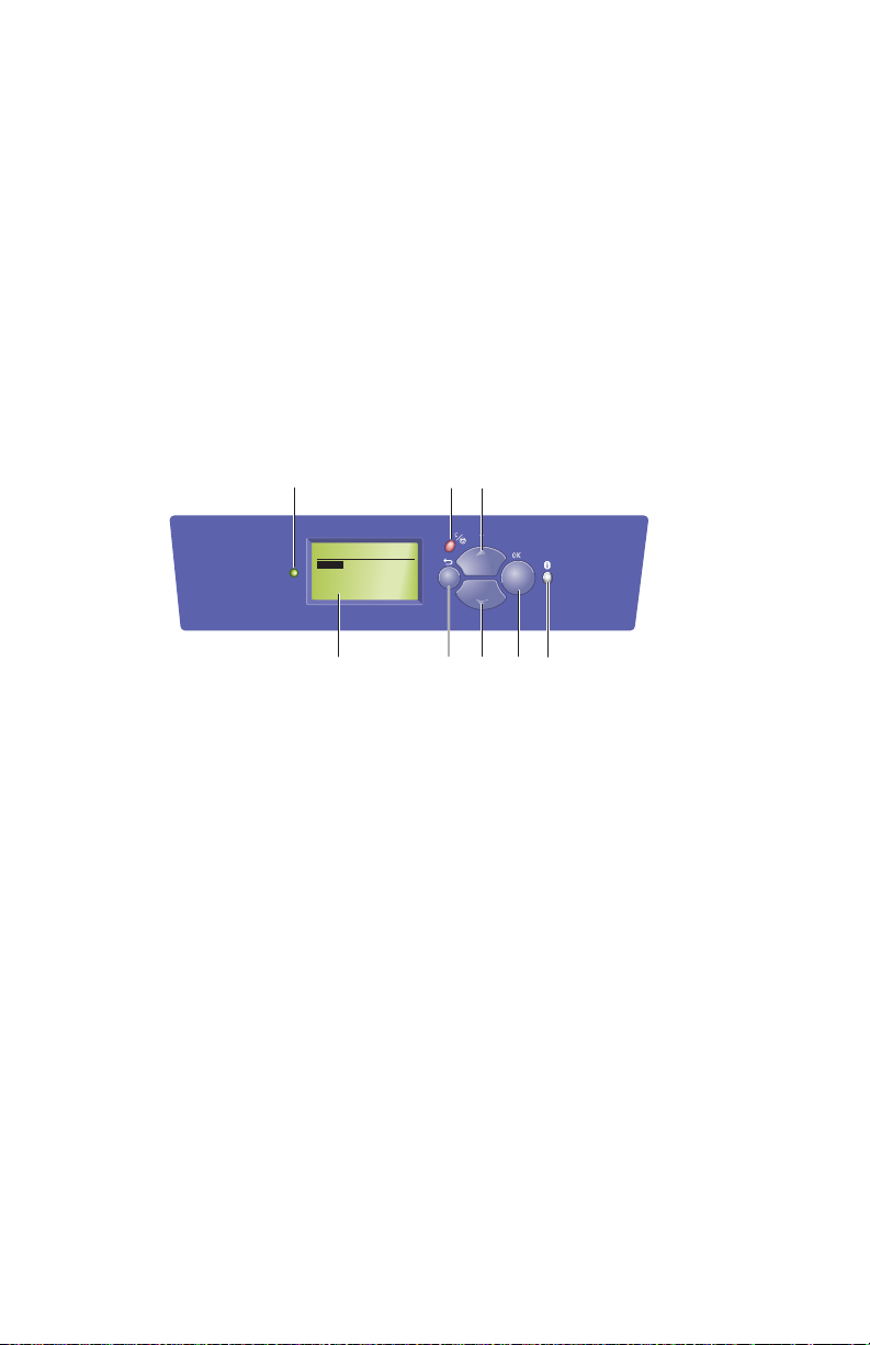
Front Panel Configuration
The Front Panel consists of one tricolor LED, a display window and six functional
buttons. These buttons navigate the menu system, perform functions, and select
modes of operation for the printer.
LED indicators:
■ Green = Ready to Print ■ Flashing Green = Receiving, Processing Data,
■ Flashing Amber = Warning ■ Flashing Red = Error
Printing or Power Saver Mode
Front Panel Feature Descriptions
31
5
Phaser 8400
PHASER 8400
READY TO PRINT
Menus
Information
Printer Identification
Troubleshooting
6
LED (Power/Status)
1
Graphic front panel display
2
Cancel button
3
Back button
4
2
4
Up Arrow button - scrolls up the menu
5
system
Down Arrow button - scrolls down the menu
6
system
OK (select) button
7
Information button - for additional
8
explanation or help
7
8
s8400-002
1-4 Phaser 8400 Color Printer
Page 21

Front Panel Shortcuts
■ To access the Service Tools menu:
From anywhere within the menu (not diagnostics): press and hold the Up Arrow
button, then press the OK button. You can also press and hold the Cancel button,
then press the OK button.
■ To set the front panel language:
Press and hold the Cancel button, then press the Information button.
■ To bypass protected menus:
Press and hold the Cancel button, then press the Back button.
■ To add Jet Substitution Mode to the Print Quality Problems menu:
From the Print Quality Problems menu: press and hold the Up Arrow button,
then press the Back button.
Service Manual 1-5
Page 22
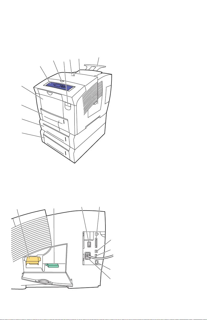
Parts of the Printer
Front View
6
5
4
3
2
1
8
7
1. Optional 525-Sheet Tray 4
9
10
s8400-003
2. Optional 525-Sheet Tray 3
3. Standard 525-Sheet Tray 2
4. 100-Sheet Multi-Purpose Tray 1
5. Front Panel
6. Exit Cover Release
7. Front Cover Release
8. Exit Cover
9. Ink Loader/Top Cover
10.Legal/A4 Output Tray Extension
Side View with Printer Interfaces
1. Maintenance Kit
1
2
4
5
1-6 Phaser 8400 Color Printer
2. Waste Tray
3. Power Cord
4. On/Off Switch
5. Parallel Cable Connection
6. USB Connection
7. Configuration Card
6
8. Ethernet Connection
7
8
3
Page 23
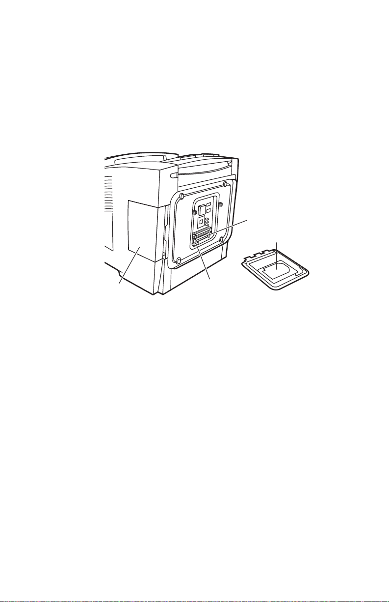
Electronics Module
The printer’s main electronics and power supply are enclosed in a metal case called
the Electronics Module. The rear panel allows access to the Electronics module,
RAM, and NVRAM chips. The printer’s hard drive is mounted on the rear panel.
When installing a new electronic module in the printer, the following components
need to be transferred from the old board.
2
1
3
1. Hard Drive (optional) 3. Configuration Card (Installed from the
2. Memory (RAM) DIMM 1 and DIMM 2 4. NVRAM
4
s8400-135
side under the interface cover.)
Service Manual 1-7
Page 24
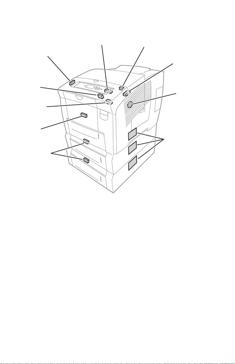
Sensors
The following graphic identifies the location of the printer’s sensors.
Exit door sensor
Preheater
sensor
Front door
sensor
Deskew
sensor
Pick sensor
(525-sheet
feeder)
Strip sensor
Paper exit sensor
Drum
temperature
sensor
Drum
position
encoder
Tray paper
size sensor
board
s8400-198
1-8 Phaser 8400 Color Printer
Page 25
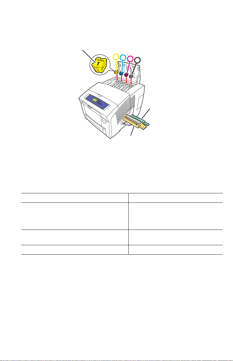
Routine Maintenance Items and Consumables
3
1
2
3
4
2
1
-
Routine Maintenance Items Consumable
1. Maintenance Kit 3. Ink
2. Waste Tray
Routine Maintenance: Consumable:
Extended
Maintenance Kit
Startup
Maintenance Kit
Waste Tray Empty every 7 Purges
*Consumable capacity is based on 5% coverage per color on plain A4 paper.
30,000 cycles (0-20%
coverage)
20,000 (20-100%
coverage)
10,000 cycles
Ink 1140 prints per stick*
Service Manual 1-9
Page 26
Printer Specifications
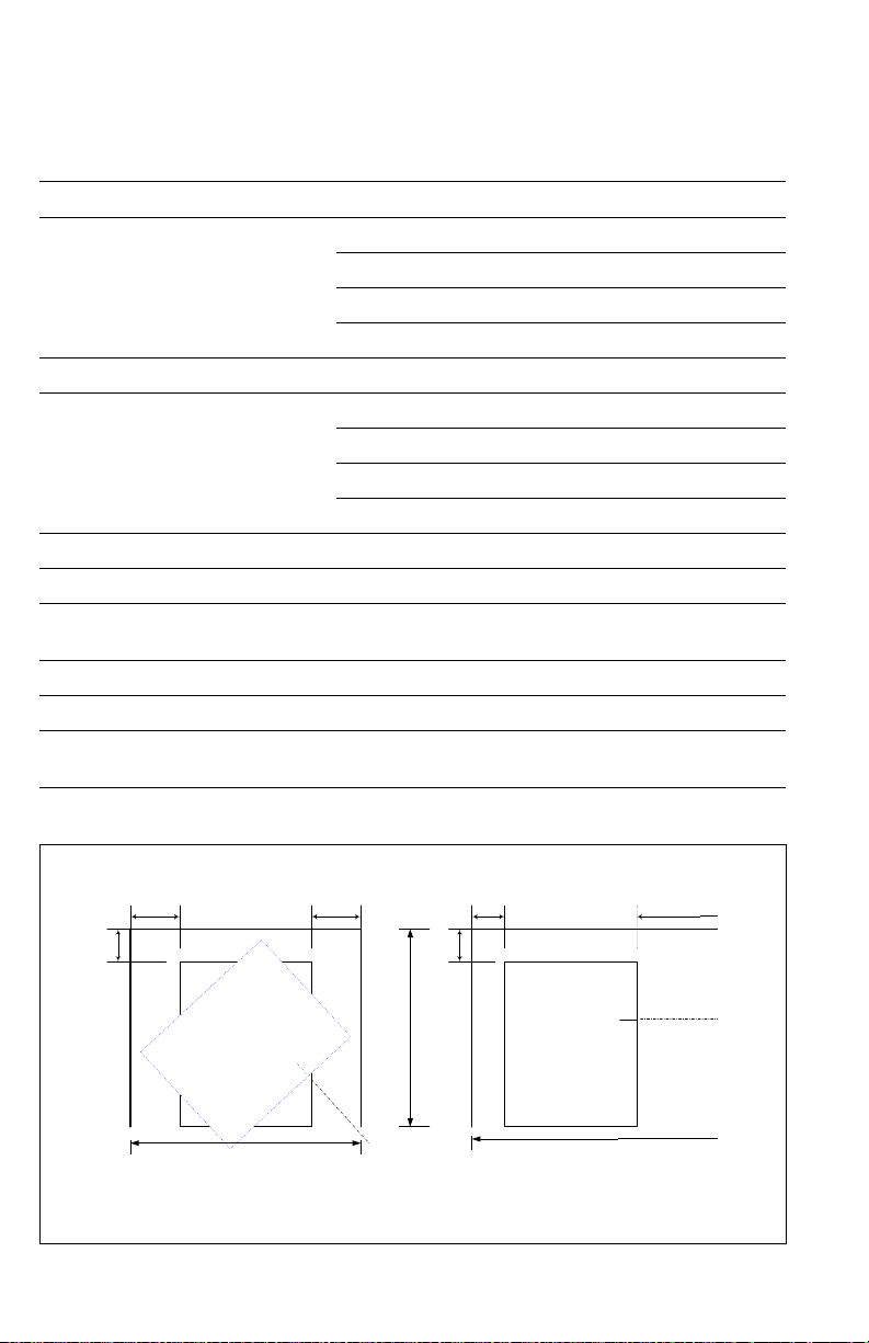
Physical Dimensions and Clearances
Print Engine Only Value
Width: 422 mm (16.6 in.) find in EIS
Depth: 514 mm (20.24 in.)
Height: 368 mm (14.48 in.)
Weight: 26.8 kg (59 lbs.)
Optional 525-Sheet Feeder Value
Width: 422 mm (16.6 in.)
Depth: 514 mm (20.24 in.)
Height: 132 mm (5.2 in.)
Weight: 5.4 kg (12 lbs.)
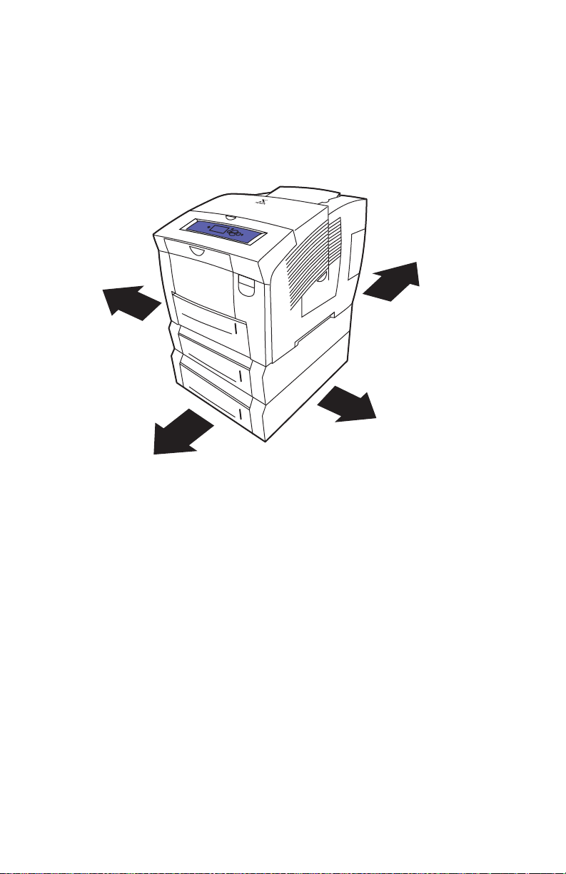
Minimum Clearances Supplemental Information
Left side & rear - 102 mm (4 in.) Required for airflow.
Right side - 394 mm (15.5 in.) Required for maintenance kit and waste tray access,
and airflow.
Front - Unrestricted Required for media tray and jam access.
Top - 559 mm (22 in.) printer only Required for inkload and jam access.
Bottom - No obstruction between
mounting surface and printer
Min. install width - 711 mm (28 in.) Requires placing printer at an angle to remove waste
Required for airflow.
tray.
A. Absolute Mi nimum
6.0 6.0
4.0
Note: All dimensions in inches
28.0
24.0
Front
B. Recommended Minimum
4.0 15.5
4.0
35.5
1-10 Phaser 8400 Color Printer
Page 27

Functional Specifications
Characteristic Specification
Printing process Solid-ink
Color medium
Operating Modes and
Resolutions
Maximum Operating
Printing Speed
First-Print-Out
(in seconds, Letter/A4)
Warm-up time:
from Off (cold start)
from power saver
Yellow, cyan, magenta, and black ink sticks, each shape-coded. The
printer uses the subtractive color system to produce the colors red,
green, and blue.
Fast Color (300x300 dpi), Standard (300x450 dpi), Enhanced
(563x400 dpi), High Resolution/Photo (525x2400)
24 ppm
As low as 6 seconds
12 minutes
4 minutes
Electrical Specifications
Characteristic Specification
115 Volt 230 Volt
Primary line voltages 90 - 140 VAC 180 - 264 VAC
Primary line voltage
frequency range
Power consumption 1250 W (peak)
Energy Star® 43 W 43 W
47 - 63 Hz 47 - 63 Hz
1250 W (peak)
120 W (idle)
230 W (average during printing)
120 W (idle)
230 W (average during printing)
Environmental Specifications
Nominal Operating Environment
Temperature
Humidity 10% - 80% RH Non-Condensing operating
Service Manual 1-11
º
C / 50º - 90º F operating
10º - 32
Page 28

Media and Tray Specifications
Paper Size Paper Type Paper Weight/Media Type
Letter (8.5 x
11 in.) or
A4 (210 x
297 mm)
Legal (8.5 x
14 in.)
Executive (7.25 x
10.5 in.) or
A5 (148 x
210 mm)
Statement (5.5 x
8.5 in.)
US Folio (8.5 x
13 in.)
A6 (105 x
148 mm)
B5 ISO (176 x
250 mm)
B5 JIS (182 x
257 mm)
Index Cards (3 x
5in.)
Plain Paper
or Letterhead
Transparency Phaser Professional Solid Ink
Card Stock
Labels Phaser Color Printing Labels
Special Phaser Professional Solid Ink Business
60–122 g/m
123–220 g/m
Transparencies
100–122 g/m
123–220 g/m
Cards
Phaser Professional Solid Ink High
Resolution Photo Paper
Phaser Premium Postcards
Phaser Weatherproof Paper
Phaser Trifold Brochures l l
60–122 g/m
60–122 g/m
123–220 g/m
2
(16–32 lb. Bond)
2
(32–59 lb. Bond)
2
(37–44 lb. Cover)
2
(44–80 lb. Cover)
2
(16–32 lb. Bond)
2
(16–32 lb. Bond)
2
(32–59 lb. Bond)
Any Tray
Tray 1 Only
2-Sided (Duplex)
l
l
l
l l
l
l
l
l l
l l
l l
l l
l l
l l
l
l
l
l l
l l
l l
l l
l l
l l
Single-sided Only
l
l
l
1-12 Phaser 8400 Color Printer
Page 29

Paper Size Paper Type Paper Weight/Media Type
Custom NOTE: Print custom size media from Tray 1 only.
Maximum: 216 mm wide x 355 mm
long (8.5 in. wide x 14 in. long)
Minimum: 75 mm wide x 127 mm long
(3 in. wide x 5 in. long)
Minimum: 139.7 mm wide x 210 mm
long (5.5 in. wide x 8.3 in. long)
Envelopes Any Tray #10 Commercial (4.12 x 9.5 in.)
Tray 1 Only #5-1/2 (Baronial 4.375 x 5.75 in.)
NOTE: Some wrinkling and embossing may occur when printing envelopes. See “Printing” on
the User Documentation CD-ROM for information on how to minimize these
occurrences.
NOTE: 2-sided printing can only be used for paper with widths greater than 5.5 in. (139.7 mm)
and lengths greater than 8.3 in. (210.82 mm).
DL (110 x 220 mm)
C5 (162 x 229 mm)
#6-3/4 (3.625 x 6.5 in.)
Monarch (3.87 x 7.5 in.)
Brochure (6 x 9 in.)
A7 (5.25 x 7.25 in.)
Choukei 3 Gou (120 x 235 mm)
Choukei 4 Gou (90 x 205 mm)
Any Tray
l ll
l l
l l
l
l
l
l
l
l
l
l
l
l
Tray 1 Only
2-Sided (Duplex)
Single-sided Only
l
l
l
l
l
l
l
l
l
l
Service Manual 1-13
Page 30

1-14 Phaser 8400 Color Printer
Page 31

Theory of Operation
In this chapter...
■ Main Printer Sub-Systems
■ Print Process
■ Printer Self-Maintenance
Section
2
Page 32

Main Printer Subsystems
Transfix system
Duplex print
path
Paper preheater
(and deskew)
Drum maintenance
kit
Drum
Printhead
Ink waste
tray
Wiper assembly
Ink loader
*Power supply
*Main
board
*Hard drive
*Configuration
card
*Power control
board
Paper/media
tray
Wave amp
*Part of the Electronics
Module
s8400-117
Overview
The printer is made up of nine major subsystems, which are described in this chapter:
■ Electronics Module
■ Process Drive
■ Media Path Drive
■ Printhead
■ Drum Assembly
■ Transfix System
■ Drum Maintenance System
■ Ink Loader
2-2 Phaser 8400 Color Printer
Page 33

■ Purge System
The electronics module includes the main board, the power control board, and the
power supply. An important component of the electronics module is the configuration
card. Printer model configuration is determined by a combination of the configuration
card feature value and other printer hardware capabilities.
The process drive is an open loop system that transmits torque to two main camshaft
assemblies. One camshaft assembly controls the transfix roller loading, and the other
controls the drum maintenance system and printhead tilt system. The media path drive
gearbox and motor assembly controls each roller in the paper transport system.
The drum maintenance system creates a thin intermediate liquid transfer surface, a
layer of silicone oil, on the surface of the drum prior to printing. The oil keeps the ink
from sticking to the drum’s surface and facilitates its transfer to the sheet of paper or
transparency film. The ink loader melts the solid ink as ink is required by the
printhead. The melted ink drips into the ink reservoirs of the printhead underneath the
ink loader.
The printhead provides the ink used by each print job. Using its 1236 jet nozzles, the
printhead can print the entire image on the rotating drum. The drum assembly and
transfix system form the key portion of the printer where imaging takes place. The
image to be printed on paper is first “printed” on the rotating drum. A sheet of heated
paper or transparency film is then passed between the drum and the transfix roller.
Under the pressure between the drum and the transfix roller, the image is transferred
to the sheet of paper. The purge system uses air pressure and a wiper blade to remove
any debris or air bubbles that may be obstructing the printhead nozzles.
Service Manual 2-3
Page 34

Electronics Module
The electronics module includes the main board, the power control board, and the
power supply. The electronics module is a field replaceable unit (FRU) assembly.
Main Board
The main board performs the image processing functions. Communication ports on
the board receive the print job image data and convert it to drive signals for the
printhead. The main board also contains the mechanical process controller, which
commands the function of the power control board. The main board sends signals to
the power control board, which are passed through to the wave amp board, which
amplifies the signal that drives the jets on the printhead. The main board supports
Non-Volatile RAM (NVRAM), memory, the hard drive, input/output ports, and the
configuration card.
NVRAM: The NVRAM memory device, located on the main board, stores front
panel defaults, network settings, calibration data, copy counts, usage profile data, and
the printer serial number, which is also referred to as the engine tracking number
(ETN). When the electronics module is replaced, the NVRAM must be transferred to
the main board in the replacement electronics module.
Memory: The main board supports two PC 133 compatible SO-DIMM SDRAM
memory modules (128 to 256 MB).
Hard Drive Support: A hard drive IDE cable is plugged into the main board from
the hard drive board. A separate power cable must be plugged into the power control
board from the hard drive board to make the hard drive board functional.
Input/Output Ports: The main board provides support for Ethernet (not supported
on the B and BD printer model configurations), Parallel, and USB 2.0 external I/O
interfaces.
Configuration Card
The configuration card is a thumbnail-sized device that plugs into the side of the
electronics module. This device stores printer information and interacts with the
printer's NVRAM chip. The configuration card supports the transfer of printer model
and network configuration information from a failed printer to a replacement printer.
When the electronics module is replaced, the Configuration Card must be transferred
to the replacement electronics module.
Information stored on the configuration card includes the feature value, ethernet
address, and personality parameters. The printer model configuration is determined
by a combination of the feature value and other printer hardware capabilities. Printer
model configuration can be transferred from one printer to another printer by
migrating the configuration card between the printers. Feature value and ethernet
address are configured at the factory, and are “read only”. The feature value is fixed in
2-4 Phaser 8400 Color Printer
Page 35

the configuration card, and does not change. Ethernet address is stored only on the
configuration card, and cannot be rewritten. The ethernet address is not written to the
NVRAM chip.
Personality parameters are a subset of network configuration parameters which are
populated to the configuration card over time, as the printer is configured by the
customer. The personality parameters are copied, or “shadowed”, from the main
board's NVRAM chip to the configuration card during the normal operation of the
printer. When the configuration card is inserted into a new printer, the personality
parameters on the configuration card are written into the NVRAM chip of the new
printer. When a printer is powered on, if it contains the configuration card of another
printer, the personality parameters are automatically copied to the NVRAM chip. If
the configuration card is removed, the printer will reboot as a B (non-networking)
model configuration. Refer to the “Configuration Card Personality Parameters”
section at the end of this chapter for a detailed list of “shadowed” personality
parameters.
Power Control Board
The power control board distributes drive voltages to operate the printer’s various
motors, solenoids and clutches. The power control board also provides the interface
that returns information from the printer's sensors to the main board. The sensors are
used to track mechanical and thermal functions, such as the position and temperature
of the printhead. The power control board also generates regulated +/- 12 volt (V) and
5 V from unregulated +/-15 V power.
Power Supply
There are no field adjustments necessary on the power supply. In general, the power
supply has two main, yet interrelated sections: the AC section and the DC section. In
the AC section, power is routed to 10 triacs which, under main board logic control,
supply AC power to the 10 heaters in the printer.
Two fuses provide current protection to the triacs. Fuse F2 and F3 protect the power
supply from, most often, a shorted triac caused by a defective heater. If the F2 or F3
fuses blow, it is best to replace the electronics module (and, of course, the defective
heater), rather than the fuse. Otherwise uncontrolled, with the fuse replaced but the
triac shorted, AC power may be applied to the heater. Each time the main board turns
on a triac to activate a heater, it is turned on for only a fraction of a second. The main
board must constantly readdress each heater it wants to remain on. This means if the
print engine firmware should fail, the heaters automatically shut off.
The printer is also protected by thermal fuses. A thermal fuse opens in the unlikely
event of a “runaway” heater following a hardware failure. The drum and the paper
preheater thermal fuses are located on the paper preheater. Additional thermal fuses
are located on the printhead and on the ink melting elements.
Service Manual 2-5
Page 36

The DC power supply generates + 3.3 V, +/- 15 V, and +/- 50 V. These voltages are
W
used directly or regulated to other voltage values as needed by various circuits in the
printer. The power control board regulates +/- 15 V to +/- 12 and other voltages. The
main board also has regulators providing + 5 V, + 2.5 V, and + 1.8 V. The power
supply outputs + 3.3 V in ENERGY STAR mode. Fuse F1 provides protection for the
switching power supply in the DC section.
arning
Do not touch the power supply; AC line voltages are present. The
power switch does not disconnect power from the printer. The
power switch signals the supply and the printer logic to begin a
shutdown sequence.
2-6 Phaser 8400 Color Printer
Page 37

AC Line
Switcher
D
r
u
m
AC Neutral
Low
H
8
P
r
e
h
t
+3.3 V
+15 V
-15 V
+50 V
-50 V
S1
AC Line
Line
Gnd Ref
Neutral
F3
F2
AC Neutral
r
I
I
I
n
n
k
k
4
3
I
n
n
k
k
2
1
r
e
e
s
2
jsrjs
s
1
I
H
1
3
H
9
H
1
2
H
1
1
H
1
0
H
4
Serial
Control
Interface
H
3
H
2
H13
H12
H
1
H11
H10
H9
H8
uProcessor
Vcc
REG
H4
H3
H2
H1
Vss
s8400-164
Service Manual 2-7
Page 38

Process Drive
The process drive is an open loop system that transmits torque to two main camshaft
assemblies. One camshaft assembly controls the transfix roller loading, and the other
controls the drum maintenance system and printhead tilt system. A small DC
servomotor powers the process drive gearbox to rotate the gears to specific positions
during the printing process. The process drive is able to actuate each camshaft system
independently or concurrently through the use of the swing arm in the gear train.
Operation of the transfix and drum maintenance system is controlled by the rotational
direction of the motor.
When the process motor rotates in one direction, the swing gear engages the lower
gears. When the motor rotates in the opposite direction, the upper gears are engaged.
Since the system is open loop, special attention to the home position of the process
drive gears and the mating camshaft gears is critical. The process drive gearbox is
mechanically keyed upon installation via gear orientations. These gear orientations
allow the printer subsystems to self home during operation. If either the gearbox or
cam gears is out of home during installation, the printer does not function properly.
Process drive Swing gear
s8400-188
2-8 Phaser 8400 Color Printer
Page 39

Media Path Drive
The media path drive gearbox and motor assembly controls each roller in the paper
transport system. A gear train located behind the motor connects it to the exit rollers,
which are built into the exit module. Gear trains located within the media path drive
assembly, along with two clutches and a solenoid, allow the motor to control the pick,
take-away, duplex, and deskew rollers.
A unique swing gear allows the pick roller and takeaway roller to rotate in the same
direction regardless of the direction the motor is rotating.
Motor
Media path drive
Swing gear
s8400-189
Service Manual 2-9
Page 40

Printhead
The printhead is the heart of the printer, spanning nearly the length of the drum. Using
its 1236 jet nozzles (309 jets for each primary color), with a horizontal motion of
slightly less than 5 mm (0.2 inches), the printhead can print the entire image on the
rotating drum. The printhead provides one size ink drop, which is used for all printquality modes.
Reservoir
Drum
Printhead
Head driver board
Purge Tube
Jet stack
s8400-122
2-10 Phaser 8400 Color Printer
Page 41

Level sense
probe
Ink
Printhead
Ink Loader
Funnel
Filter
Purge
Valve
Black
Yellow
Cyan
Magenta
s8400-182
The printhead’s jet stack is fabricated from a stack of chemically etched steel plates
which are brazed together to form the jet array. Channels formed by the stacked plates
route ink past the 1236 individual, piezo-electric crystal-driven diaphragms, which
force the ink in droplets out the 1236 corresponding nozzles. Looking at the printhead
face, the nozzles are arranged in 12 rows, in color order KYKYKYCMCMCM, where
K = black, Y = yellow, C = cyan, and M = magenta. During the printing process, the
printhead would only have to travel approximately 14 pixels horizontally to provide
complete coverage. However, the printhead travels much further, depending on print
resolution, to interlace each jet with the output of neighboring jets.
Service Manual 2-11
Page 42

The jet array is bonded to a cast aluminum ink reservoir. The reservoir supplies the
molten ink to the jet array. Heaters in the reservoir and the jet array maintain the ink at
a temperature of about 140o C for printing.
X-Axis
shaft
X-Axis hook
Tension spring
Printhead
X-Axis
shaft
Nose
cone
X-Axis
Motor
gear
Drum
s8400-124
X-Axis or lateral movement of the printhead is accomplished using a stepper motor
driving a fine-thread screw system. The printhead, mounted to the X-Axis shaft,
moves laterally across the surface of the drum.
To find the printhead home position, the X-Axis system drives the printhead in an
open-loop. The printhead is driven against the left printer frame for a few seconds,
and then reversed a set distance. A tension spring links to the printhead’s left shaft,
and provides a preloaded tension so the printhead moves smoothly.
2-12 Phaser 8400 Color Printer
Page 43

Printhead Tilt
The printhead is able to rotate into four basic positions:
1. Printhead lock / ship position (19.5 degrees) The printhead restraint pins are
resting against the right and left locks. In this position, the printhead tilt arm/
follower is free of the tilt cam, and the head is secured for shipping.
2. Wipe position (12 degrees) The printhead tilt arm/follower is engaged with the
tilt cam, and the head overload spring contact is engaged with the overload
spring-plate to provide the correct force for the wiper.
3. Standby position (20.9 degrees) Allows the wiper to clear the printhead in order
to be in the start wipe printhead position, and also allow the printhead locks to
pivot and lock or unlock the printhead. In this position, the printhead tilt arm/
follower is engaged at the standby position of the tilt cam.
4. Print position (0 degrees) The printhead is forward and resting against the right
and left head-to-drum buttons. The head-to-drum buttons define the space
between the jet stack and the drum.
The tilt cam tilts the head into the basic four positions listed above. The cam has five
special features and associated functions:
1. The cam is combined with a missing tooth gear that allows the cam to be inactive
in the print position, which frees the process drive to perform other printer
operations.
2. The cam has a latching feature to unlatch and latch the missing tooth gear to
engage the printhead tilt drive train.
3. The cam profile has a standby dwell (the portion of the cam that has a constant
radius), that holds the printhead back in the standby position
4. The cam profile has a wipe dwell the holds the printhead back in the wipe
position.
5. The cam profile increases the power consumption at a specific phase of rotation.
This allows the software to identify a power consumption footprint that alerts the
system to a fault when the head is locked in error.
The printhead is tilted away from the drum and locked for shipping. The printhead is
locked if the green head lock indicator is above the level of the tray. When the
printhead is locked in the shipping position there are three key restraining elements:
1. The printhead is restrained from rotating from the shipping position by pins
extending from both ends of the printhead into a pocket. These pockets are
defined by dampening pads that limit motion to the back and polycarbonate locks
that pivot into the lock position and limit forward motion toward the drum. The
locks are held in the lock position by the wiper carriage, and are spring-loaded to
normally be unlocked.
2. The printhead is restrained at the X-Axis shafts by the right and left head
restraints that limit motion at both ends of the printhead.
3. The printhead is limited to the nominal motion of 1.7mm in the X-Axis (left /
right side motion when the printhead is back and locked) by the right lock and the
left home stop on the left side frame.
Service Manual 2-13
Page 44

DM Cam
gear
Printhead restraint
Drum
Printhead
Tilt gear
engaged
Tilt gear
s8400-166
In print position (0 degrees), the printhead is forward and resting against the right and
left head-to-drum buttons. The head-to-drum buttons define the space between the jet
stack and the drum. The process drive is activated, which drives the drum
maintenance camshaft such that the tilt gear train is engaged. The tilt cam tilts the
printhead into the print position. The cam is combined with a missing tooth gear that
allows the cam to be inactive in the print position, which frees the process drive to
perform other printer operations.
The cam has a latching mechanism to unlatch and latch the missing tooth gear, to
engage the printhead tilt drive train. The cam’s latching mechanism also holds the tilt
gear in place. A leaf spring applies constant pressure to engage the gear when the
latching mechanism is released. The arm of the latching mechanism is inside the
frame, the rest is visible, outside the frame. Arrows located on the latching
mechanism and on the frame indicate when the printhead is in print position. When
the arrows on the latching mechanism and frame are aligned, it indicates that the
printhead is in print position, and the tilt gear is disengaged from the process drive.
2-14 Phaser 8400 Color Printer
Page 45

The latching mechanism is actuated by a small movement of the wiper. Through a
follower gear, the compound gear drives the tilt cam gear clockwise. A cam follower,
mounted on the lower end of the tilt arm, follows the rotating tilt cam gear, which tilts
the printhead. After one revolution of the tilt gear, the latching mechanism is pulled
back into position by the return spring.
As viewed from the left side of the printer, when the arrows do not align, the tilt gear
is engaged.
Head tilt compond gear Tilt drive gear
Tilt gear engaged
s8400-186
To accommodate printhead maintenance, the printhead can be tilted back away from
the drum. This creates room for the wiper to be moved into position in front of the
printhead faceplate. The process drive drives the gears to the tilt compound gear train.
The drum maintenance camshaft drives the gear train to tilt the printhead.
Service Manual 2-15
Page 46

Drum Assembly
The drum assembly and transfix system form the key portion of the printer where
imaging takes place. The drum assembly and transfix system are separate, yet
interrelated. This section discusses the drum assembly. The next section goes into
more detail on the transfix system.
In operation, the image to be printed on paper is first “printed” on the rapidly rotating
drum. The paper preheater heats a sheet of paper or transparency film to prepare it for
the image transfer process. The heated paper is then passed between the drum (now
rotating much more slowly) and the transfix roller. Under the pressure between the
drum and the transfix roller, the image is transferred to the sheet of paper. An encoder
disk and sensor on the left end of the drum monitors the drum’s speed and position.
Tranfix roller
Paper path
Paper preheater
Drum
Drum heater
s8400-118
The drum heater heats the surface of the drum to about 60
The drum heater does not rotate. The heater is inside the drum, and is controlled by
the drum heater relay board. The drum heater consists of two resistive heater coils that
operate in series for 220 V and in parallel for 110 V operation. The series/parallel
operation is controlled by the drum heater relay board. A temperature sensor in
contact with the drum surface monitors the drum temperature. The main board
interprets the sensor’s signal and turns on the drum heater and drum fan to heat the
drum, or turns on the drum fan alone to cool the drum.
o
C (140oF) for imaging.
2-16 Phaser 8400 Color Printer
Page 47

The drum is driven by a closed-loop servo motor which, through a single reduction
W
belt drive, rotates the drum at a high speed for imaging and a constant low speed for
image transfer to paper. The Y-Axis is on an active tension system, which allows the
pulley to float and the spring to actively adjust the tension during operation.
Note
The drum rotates in different directions for each process.
■ Transfix CW
■ Maintenance CCW
■ Printing CCW
Single reduction
belt drive
Pulley
Drum temperature
sensor
Y-Axis motor
Tension spring
Y-Axis
Encoder
arning
Always keep your fingers away from the drum drive system; it
uses a closed-loop servo drive system, which is inherently
dangerous. Since the motor speeds up if it senses the drum drive
system slowing down, fingers caught in the drum belts and gears
can be severely injured.
Service Manual 2-17
Fan
s8400-146
Page 48

Transfix System
W
The transfix roller applies pressure to the back side of the paper as it moves between
the transfix roller and drum. This pressure transfers the image from the drum to the
paper. A set of springs determines how much pressure the transfix roller applies in the
load module against the drum. The pressure must be uniform across the length of the
transfix roller to avoid paper wrinkles and light spots on the prints.
After the transfix roller is engaged, the drum rotates to advance the paper during the
transfix process. The drum continues to advance the paper until the transfix roller is
disengaged. The transfix roller is lifted and lowered by the action of the process drive.
All gears move to rotate the transfix camshaft to bring the transfix roller into contact
with the drum. The gears reverse to rotate the transfix roller back to its original
position, except when printing from Tray 1 or on envelopes. The transfix load springs
and double lever arms increase the force when the camshaft is engaged.
arning
Never attempt to adjust or increase the transfix pressure on the springs.
Transfer roller
Transfix load arm
Transfix load
module
Transfix
load
spring
Transfix
cam
Drum
s8400-119
2-18 Phaser 8400 Color Printer
Page 49

Drum Maintenance System
The drum maintenance system creates a thin intermediate liquid transfer surface, a
layer of silicone oil, on the surface of the drum prior to printing. The oil keeps the ink
from sticking to the drum’s surface and facilitates its transfer to the sheet of paper or
transparency film. The oil is contained in a porous foam roller.
Prior to each print, a cam, driven by the process motor, raises the pivot plate, which
raises the oil roller against the rotating drum. A compliant wiper blade, also raised by
the same cam, assures that the oil film is smooth and even across the drum’s surface.
The process drive rotates in one direction, which rotates the drum maintenance
camshaft, and raises the drum maintenance system to the drum. The process drive
rotates in the opposite direction to lower the drum maintenance system. The blade
removes oil that is drained back into the maintenance kit drawer, through a felt filter,
to the oil roller for reuse. As the drum completes one rotation, the rotating cam lowers
the oil roller and then a moment later, lowers the blade.
The drum has a floating deadband, which is the narrow section of the drum containing
excess oil and other debris. The oil bar is left on the drum surface when the blade is
removed from the drum. This oil bar location is controlled to keep it outside of the
print area.
An EEPROM chip, built-in to the maintenance kit, stores the number of oiling cycles
performed by the drum maintenance system. The EEPROM stores the number of
prints remaining to track consumable life. At printer startup, four oiling cycles are
performed to condition the drum.
Drum
Oil on drum
Blade
Drum maintenance
camshaft
Drum maintenance
pivot plate
Maintenance roller
s8400-121
Service Manual 2-19
Page 50

Ink Loader
The ink loader consists of four parallel channels with an ink melting element at the
end of each channel. Ink sticks, one color loaded in each channel, are pressed by coilspring pressure into the melting elements. As ink is required by the printhead, the
appropriate color’s melting element is activated and the end of the ink stick is melted.
The melted ink drips into the ink reservoirs of the printhead underneath. Sensors in
the ink loader alert the customer to install more ink sticks before the current sticks are
completely consumed.
If the ink level sensors inside the printhead detect that the printhead has run out of ink,
but the ink low/out sensors are not activated, the front panel reports an “Ink Jam”
error.
Ink loader door
Ink stick
Ink melt units
Ink low sensors
Ink out sensors
Printhead
s8400-136
2-20 Phaser 8400 Color Printer
Page 51

Purge System
Proper printhead operation is dependant on the correct operation of the Purge System.
The purge system uses air pressure and a wiper blade to purge any debris or air
bubbles that may be obstructing the printhead nozzles. The waste ink that is expelled
during the purge is funneled into the waste tray. Following the purge, a wipe operation
is performed on the faceplate using the wiper blade. After the wipe, a cleaning page is
printed.
Wiper blade
2.5 sec
Printhead
To perform a printhead maintenance cycle, the printhead is first tilted away from the
drum, to allow the wiper assembly to pass by. The wiper blade is then raised in front
of the printhead. Wiper movement is governed by the media path drive, by engaging a
clutch on the exit shaft of the printer. The purge pump applies pressure to the ink
reservoir for approximately 2.5 seconds. Valves in the reservoir seal when pressure is
applied. The pressurization ejects a small amount of ink from the jets. Following the
pressure purge, the printhead is tilted into the wiper assembly and the wipe cycle
begins. The pump runs again with the solenoid for approximately 30 seconds,
creating a neutral balance between pressure and ink. The wiper blade lowers and
wipes excess ink from the jets into the ink waste tray. A proper purge will layer the
length of the waste tray with a single layer of ink about 20 mm wide.
Purge tube
Purge pump
s8400-147
Service Manual 2-21
Page 52

The level of the ink in the reservoir is kept at a constant level. If the pressure purge
W
tubing is pinched, the printhead may not purge properly. In addition, because the
purge tubing also acts as a vent to atmosphere when not purging, a more serious
failure may occur if the ink overfills because the reservoir is not allowed to vent
properly.
arning
When servicing the printer be careful of the purge system as it passes the
printhead. If a damaged wiper blade of the purge system catches on the
printhead, it could propel hot liquid ink upward into your face.
30 sec
Printhead
Solenoid valve
(Open during wiper action)
Wiper assembly
Drum
Purge tube
Purge pump
Printhead
Wiper
s8400-148
2-22 Phaser 8400 Color Printer
Page 53

Print Process
W
Once an image has been processed and a printing bitmap created, a print cycle begins.
The printhead and drum are brought up to their operating temperatures and the ink
levels in the ink reservoirs are checked. Ink is added from the ink loader, if necessary.
At the ready state, the print process consists of the following steps, which are
described in this section:
■ Drum Preparation
■ Printing
■ Paper Pick
■ Transfixing and Exiting
arning
Keep your fingers away from the Y-Axis drum rotation drive
system; it uses a closed-loop servo drive system, which is
inherently dangerous. Since the motor speeds up if it senses the
drive system slowing down, fingers caught in the belts and gears
can be severely injured.
Service Manual 2-23
Page 54

Drum Preparation
To prepare the drum, a thin coating of silicone oil is applied to the surface of the
drum. First the drum is rotated. Next, the oil roller and blade of the drum maintenance
system are raised into contact with the drum. To accomplish this, the process drive
rotates the drum maintenance camshaft lifting the oil and wiper blade to the drum.
The cams on the ends of the camshaft push against followers on each side of the drum
maintenance system, forcing the oil roller and blade against the drum. The drum is
rotated against the oil saturated roller.
Drum
Oil on drum
Blade
Drum maintenance
camshaft
Drum maintenance
pivot plate
Maintenance roller
s8400-121
2-24 Phaser 8400 Color Printer
Page 55

Printing
To print, the drum starts rotating at a speed dependent upon print resolution. As the
drum reaches the correct speed, the jets begin to fire to deposit the image on the oiled
portion of the drum. As the jets fire, the printhead moves from right to left to complete
the image on the drum.
When printing, the printer performs a “six-jet interlace,” in which each jet lays down a
particular number of pixel columns, depending on the print resolution. Each jet lays
down one pixel column for each drum rotation, which varies from eight to 16
rotations, depending on the print resolution. Interlacing “averages out” the variability
between jets by interlacing each jet with other jets. In some test prints the printhead
moves to the right and lays down 309 parallel bands of ink. Each band is composed of
15 pixel columns of dots from an individual jet.
Jet substitution allows a better performing jet to be used in place of a missing or
poorly performing neighboring jet. When jet substitution mode is used, the printhead
makes a second, right to left movement to deposit the pixel columns of the jets being
substituted. Refer to "Jet Substitution Mode" on page 6-9.
Service Manual 2-25
Page 56

Paper Pick for Trays 2 - 4
Note
Trays 3 and 4 are 525-Sheet Feeders.
To pick a sheet of paper, the media path drive starts, and the pick clutch engages,
which turns the pick roller and the nudger roller. The nudge roller advances one sheet
of paper forward into the pick nip. The retard roller prevents two sheets from
advancing. The sheet of paper continues past the take-away rollers until the sheet
completes the deskew process. When using the optional 525-sheet feeder, paper is
pre-picked from the tray and staged in the paper path while the printer is printing
previous pages.
The deskew process uses a reverse/buckle deskew for all three paper paths. The paper
is driven against the non-rotating rollers, which are reversing during simplex, causing
a buckle in the paper ensuring the leading edge is straighten to prevent skewing. The
deskew rollers do not reverse during duplex printing.
Strip sensor
Deskew sensor
Exit sensor
Preheat sensor
s8400-167
2-26 Phaser 8400 Color Printer
Page 57

Paper Pick for Tray 1
For Tray 1, the paper pick process is different than the pick process used by the other
trays. To pick a sheet of paper, the Tray 1 solenoid is fired, and the drive gear rotates
slightly to engage with the drive train. A bias force provided by the lift plate force
against a cam causes the roller to rotate enough so the missing tooth gear engages the
drive train. The pick roller rotates to pick the paper, and the separator pad assembly
prevents multiple sheets from being picked by the pick roller.
Key differences in the Tray 1 pick process include:
■ Lift plate force is optimized to support heavier paper
■ 100-sheet capacity
■ Pick roller creates the buckle for the deskew process
■ Pick roller drive disengages when the door is opened and closed
■ Pivoting separator pad to prevent it from binding
Drive gear
Spring loaded lift plate
Cam
Pick roller
Separator pad
s8400-190
Service Manual 2-27
Page 58

Transfixing and Exiting
Transfixing and exiting consists of four major functions:
1. Staging the paper for rendezvous with the image on the drum and transfix roller
nip.
2. Loading the transfix roller and engaging the drum stripper blade assembly.
3. Stripping the paper from the drum.
4. Exiting the paper from the printer, or exiting the paper for (2-sided) duplex
printing.
Tripping the preheat exit sensor sets up a series of events, which take place on a
predetermined schedule. Paper is transported through the preheater to thermally
prepare it for transfixing. The preheat sensor detects the paper’s presence, and
accurately references the leading edge of the paper with the image on the drum. Based
on the timing information from the paper preheater exit sensor, the transfix roller is
lowered onto the leading edge of the media in the nip. Timing is based on the sensor
ensuring the image is perfectly aligned for transfix to the paper. The transfix roller is
lifted and lowered by the process drive.
2-28 Phaser 8400 Color Printer
Page 59

.
Transfix load
module
Transfix
load
spring
Transfix load arm
Transfix
cam
Transfix cam
Transfer roller
Drum
Transfix roller
gear
Process drive
s8400-192
Service Manual 2-29
Page 60

At the point which the transfix roller is loaded, but before the drum begins to rotate,
the paper stripper solenoid is engaged. The paper stripper is actuated by energizing
the paper stripper solenoid, which is mounted on the upper inner duplex guide. The
solenoid activates the strip solenoid lever, which in turn rotates the paper release
carriage until it hits the transfix ground pins, which causes the paper release blade to
momentarily drop onto the deadband of the drum, catching the leading edge of the
sheet of paper and guiding the paper to the rotating exit rollers.
After the transfix roller is engaged, the drum rotates to advance the paper and transfix
the image. All gears move to rotate the drum transfix camshaft to bring the Transfix
Roller into contact with the drum. The transfix roller nip applies the load necessary to
transfer the image to the paper from the drum. Once the image is transferred, the drum
stops rotating and the transfix roller is lifted by the process drive. After the leading
edge of the paper is beyond the paper release guide, the paper release solenoid is deenergized. Once the solenoid is de-energized, and the solenoid return spring provides
a force to move the solenoid plunger out of the solenoid coil and in turn rotate the
paper release carriage back to its ready position.
The deskew rollers are not driven during transfixing. The media path drive rotates the
exit rollers in the correct direction to pull the paper out, with the deskew clutch deenergized. As the process drive lifts the transfix roller, the exit rollers deposit the
paper into the output tray, ending the print cycle.
2-30 Phaser 8400 Color Printer
Page 61

Strip solenoid
Release blade
Preheat sensor
Transfix roller
Exit sensor
Paper preheater
Strip
sensor
s8400-204
Service Manual 2-31
Page 62

Duplex Printing
When duplex printing, the exit rollers pull the paper to a predetermined location, such
that the trailing edge of the paper is adjacent to the exit rollers. Then, the exit rollers
pull the paper back into the duplex path. The paper deskews against a non-rotating
deskew nip. From this point on, the print is processed through the paper preheater and
transfix system to the exit tray in the same manner as a single-sided print.
Exit sensor
Deskew sensor
Exit roller
Strip sensor
Preheat sensor
Duplex Roller
Duplex roller
s8400-191
2-32 Phaser 8400 Color Printer
Page 63

Transfix and Print Speeds
Transfix Speeds
Characteristic Setpoint, Paper Media
Fast Color Standard Enhanced High Res/
Photo
Peak Transfix Speed,
Simplex tray feed
Peak Transfix Speed, Duplex 5 ips 5 ips 5 ips 5 ips
Peak Transfix Speed, Legal 20 ips 17 ips 13 ips 7 ips
Peak Transfix Speed, Tray 1 13 ips 7 ips 7 ips 7 ips
First sheet transfix speed 7 ips 7 ips 7 ips 7 ips
20 inches per
second (ips)
17 ips 13 ips 7 ips
Setpoint, OHP Media
Peak Transfix Speed 5 ips
Approximate Print Speeds
Tray (source) /
Resolution
Tray 1
Fast Color (300x300 dpi) 10 pages per minute (ppm) 10 sides per minute (spm)
Standard (300x450 dpi) 9 ppm 9 spm
Enhanced (563x400 dpi) 8 ppm 4 spm
High Res/Photo (525x2400) 6 ppm 3 spm
Simplex, A4 Paper Auto Duplex, A4 Paper
PCL 600 x 300 Mode
PCL 600 x 600 Mode
6.5 ppm
3 ppm
Tray 2 - 4
Fast Color (300x300 dpi) 24 ppm 15 spm
Standard (300x450 dpi) 18 ppm 13 spm
Enhanced (563x400 dpi) 12 ppm 11 spm
High Res/Photo (525x2400) 7 ppm 7 spm
PCL 600 x 300 Mode
PCL 600 x 600 Mode
13 ppm
6 ppm
Service Manual 2-33
Page 64

Printer Self-Maintenance
W
To maintain peak operation, reliability, and print quality, the printer has several
automatic or semi-automatic maintenance functions. These functions may be started
automatically after a certain number of prints or during printer startup, or they may be
started by the customer if a print-quality defect is noted.
■ Printhead Maintenance Cycle (Eliminate Light Stripes)
■ Paper Preheater Cleaning (Remove Print Smears)
■ Transfix Roller Oiling
■ Drum Cleaning (Chase Page)
Printhead Maintenance Cycle (Eliminate Light Stripes)
The printhead maintenance cleaning cycle removes bubbles or foreign matter that
cause a printhead jet to malfunction. Three basic actions take place during a cleaning
cycle:
■ Purging
■ Wiping
■ Printing the Cleaning Page
There is one basic type of cleaning cycle performed by the purge system. The first
customer purge and the manufacturing purge consist of two basic cleaning cycles
performed sequentially. A cleaning cycle is performed when the printer is first
powered on, if the ink reservoir has cooled to the point that a cleaning cycle is
triggered. A cleaning cycle is not performed when the printer is coming out of
standby mode. Refer to the purge system topic in this chapter for more detail on the
printhead maintenance cycle.
arning
When servicing the printer be careful of the purge system as it passes the
printhead. If a damaged wiper blade of the purge system catches on the
printhead, it could propel hot liquid ink upward into your face.
2-34 Phaser 8400 Color Printer
Page 65

Paper Preheater Cleaning (Remove Print Smears)
This customer-initiated cleaning procedure is selected by choosing Remove Print
Smears on the front panel’s Print Quality Problems menu. This procedure cleans
ink out of the paper preheater that may have been deposited there. Heavier-weight,
high-grade quality paper works best for this procedure. Ink can also be deposited if a
jammed print, with ink on it, was pulled backwards through the paper preheater.
In the paper preheater cleaning cycle, these events take place:
1. The customer selects the Remove Print Smears menu item.
2. The printer overheats the paper preheater to about 100
inside the paper preheater. Ordinarily the paper preheater runs at temperatures of
between 60
3. The printer picks and passes approximately 12-24 sheets of paper through the
print path. The first few sheets absorb and remove ink from the paper preheater.
The printer continues to pass sheets of paper though to cool the preheater until
normal operating temperature is reached. If duplex capability is enabled, 5 sheets
of paper go through the simplex paper path and up to 20 sheets go through the
duplex paper path.
4. The printer returns to the Print Quality Problems menu.
Because of the higher paper temperatures involved, this function can also be used to
clean the drum surface of ink deposits caused by a contaminated blade on the drum
maintenance system.
o
C and 65o C for paper or transparency film printing.
o
C, softening ink trapped
Transfix Roller Oiling
Oiling the transfix roller prevents ink from sticking to it. Every 50 prints, the printer
performs a transfix roller oiling cycle. During this cycle, oil is applied to the drum as
it would be during a print cycle. Then, the transfix roller is lowered against the drum
and the drum rotates, which transfers some of the oil to the transfix roller. Finally, the
transfix roller is raised to its standby position.
Drum Cleaning - Chase Page
The printer performs a drum cleaning with a chase page automatically anytime a
paper jam occurs. The chase page transfers any image, which may not be complete,
off the drum. The printer then attempts to reprint the print that jammed. The chase
page is processed the same as a regular print, except that the drum is not oiled and no
image is printed on the drum (since an image is already printed on the drum).
Service Manual 2-35
Page 66

Configuration Card Personality Parameters
Configuration Card “Shadowed” Personality Parameters
NCL Subject NCL Item Size (bytes)
N/A “version” not NCL
parameter
NEST Base Printer Name 48
NEST SysAdmin Contact 128 (truncated from 256)
NEST Printer Location 128 (truncated from 256)
NEST Asset Identifier 128 (truncated from 256)
IP Host Name 64
IP Domain Name 256
IP Network Mask 4
IP IP Address 4
IP Default Gateway 4
IP BOOTP/DHCP 1
IP DDNS 1
IP SMTP Server 256
IP IP Source 1
IP TCP/IP 1
IP AutoIP 1
version (of the layout of personality
parameters)
4
IP DHCP Vendor Class ID 48
DNS RESOLVER Primary Name Server IP Address 4
DNS RESOLVER Secondary Name Server IP Address 4
DNS RESOLVER MulticastDNS 1
NBNS (WINS) Enable 1
NBNS (WINS) WINS Note Type 1
NBNS (WINS) Primary WINS Server 4
NBNS (WINS) Secondary WINS Server 4
Ethernet Speed 1
HTTP On 1
2-36 Phaser 8400 Color Printer
Page 67

Configuration Card “Shadowed” Personality Parameters (Continued)
NCL Subject NCL Item Size (bytes)
HTTP Information Forwarding 1
HTTP SMTP Server Automatic 1
HTTP Legal Settings 1
HTTP Admin_Password 11
HTTP Admin_Username 11
HTTP KeyUser_Password 11
HTTP KeyUser_Username 11
HTTP Admin_HostAccessList 256
HTTP KeyUser_HostAccessList 256
Notify On 1
IPP Authentication Scheme 1
IPP IPP user name 11
IPP IPP password 11
FTP Login Password 33
Security Print Hosts 256
AppSocket On 1
AppSocket Enabled 1
LPR On 1
LPR Enabled 1
FTP On 1
FTP Enabled 1
IPP On 1
IPP Enabled 1
MIME On 1
MIME Enabled 1
EtherTalk On 1
EtherTalk Enabled 1
PSERVER On 1
Service Manual 2-37
Page 68

Configuration Card “Shadowed” Personality Parameters (Continued)
NCL Subject NCL Item Size (bytes)
PSERVER Enabled 1
PSERVER_IPX Enabled 1
Notes:
1. “Parallel” and “USB”, “On” and “Enabled” parameters have not been identified as
personality parameters. They are not tied to networking.
2. NCL = Nest Configuration Library
2-38 Phaser 8400 Color Printer
Page 69

Error Messages and Codes
In this chapter...
■ Power-Up Error Messages and LED Codes
■ POST (Power On Self Test)
■ Fault Code Definitions and Troubleshooting
■ The BIST (Built-In Self Test)
■ Fault Code Definition Table
■ 3-Digit Jam Codes Definition Table
Section
3
Page 70

Introduction
This section covers troubleshooting procedures for the printer using front panel error
messages and codes. Some procedures require running service diagnostic test
functions to verify that a specific printer part is operating correctly. For information
on Service Diagnostics and all internal printer test functions, see the table "Service
Diagnostics Mode Menu" on page 4-5.
To troubleshoot problems, such as startup and power on, media, paper path, printquality or image problems, and electrical failures not associated with a front panel
message or code, refer to the section "General Troubleshooting" on page 4-1.
If an error message or code is not visible on the front panel, the Service Usage Profile
report and Printer Status page list errors reported by the printer.
Power-Up Error Messages and LED Codes
The printer has three sets of tests that are run when the printer is first powered on:
Built-In Self Tests (BIST), Power On Self Tests (POST), and Print Engine Self Tests
(PEST). BIST verifies basic Electronics Module CPU operation and reports failures
with interface panel LED blink codes (
flashes equals error code 7
Electronics Module CPU to other parts of the Electronics Module and to some other
systems of the printer. PEST runs once Postscript is operational, and checks for
connection to and operation of, various system components.
POST testing initializes the front panel and if an error occurs a POST error message
will be displayed on the front panel LCD. POST errors are also displayed using
interface panel LED patterns in case the communication path to the front panel has
failed.
Some POST errors are "soft" errors that do not prevent the printer from powering up
completely. These errors are displayed on the front panel for 5 seconds and then the
printer continues through the remainder of POST. Because soft errors do not stop the
printer from powering up, there are no rear panel LED codes associated with them.
Most soft errors will also cause the printer to print a Startup Page with the error
message on it. BIST and POST errors are not stored in the fault history logs.
). POST checks communication paths from the
The sum of the flashes equal the error code, 7
Jam Codes
The Jam Codes provide a basis for troubleshooting printer problems that occur as the
result of misfeeds or jams within the paper path. Refer to the "3-Digit Jam Codes" on
page 3-35 and to the Xerox infoSMART knowledge base at www.xerox.com/office/
infoSMART for the latest information on Jam Code interpretation.
3-2 Phaser 8400 Color Printer
Page 71

The BIST (Built-In Self Test)
These tests occur immediately at power-up, before the front panel is initialized.
BIST Rear Panel LED Codes
PE LED PS LED Description
Off or 1
Blink and
then off
On Solid
(dimly)
Off PS and
1 Rapid
2 Rapid
3 Rapid
Off or 1
Blink and
then off
On Solid
(dimly)
front
panel 1/2
sec. blink
blinking
blinking
blinking
The power supply could not remain regulated when the DC power
was applied so it was shut down. Follow the troubleshooting
procedures for electrical shorts and check the power supply fuses.
Initialization failure, the printer is held in reset mode. This can be
caused by an Electronics Module fault or a +3.3 V power supply
regulation failure.
Boot loader memory test failure. Ensure that RAM modules are
properly seated and that correct RAM type is installed.
CPU Bridge and/or PCI bus is not communicating.
ROM not responding.
System hangs during code initialization.
1. Unplug all cables from the Electronics Module.
2. Plug in the power cable.
3. Power on the Electronics Module
4. Check to see if the problem recurs.
5. Try reseating the RAM DIMMs.
6. If 1 through 5 do not correct the problem, replace the Electronics
Module.
Service Manual 3-3
Page 72

POST (Power On Self Test)
When these tests begin the front panel has been initialized. In most cases, if an error
occurs, a text message is displayed on the front panel along with an LED blink code
flashing on all three LEDs (front panel LED, PS LED and PE LED).
flashes, blinking in increments of 5, equal the error code. For example, 7 flashes
equals error code 7
.
POST (Power On Self Test) Error Messages
Description
* Before replacing the electronics module do the following:
1. Unplug all cables.
Front
Panel
Error
Code
PS, PE
and Front
Panel
LEDs
2. Plug in the AC power cable and power on the electronics
module.
If the error blink pattern has changed, the problem may not be in
the electronics module. Refer to "Electronics Troubleshooting" on
page 4-51.
The sum of the
01.01 Flutter then
01 blinks
02.01 Flutter then
02 blinks
02.02 Flutter then
02 blinks
03.01 Flutter only Titan ID read failure, POST soft error.
03.02 Flutter then
03 blinks
03.03 Flutter only. Titan version mismatch, POST soft error.
03.04 Flutter then
03 blinks
04.01 Flutter then
04 blinks
04.02 Flutter then
04 blinks
04.03 Flutter then
04 blinks
04.04 Flutter then
04 blinks
05.01 Flutter then
05 blinks
05.02 Flutter only Communications error. PLD I/O Board serial, mismatch, POST soft
* Bad error code, POST hard error.
* Failed machine check, POST hard error.
* System panic, POST hard error.
* Titan mismatch, POST hard error.
* Titan access failure, POST hard error.
* Bandit ID read failure, POST hard error.
* Bandit ID mismatch, POST hard error.
* Bandit TMVL mismatch, write/read failed, POST hard error.
* Bandit TMVH mismatch, write/read failed, POST hard error.
* Communications error. PLD I/O Board serial, link down/bad
parity, POST hard error.
error.
3-4 Phaser 8400 Color Printer
Page 73

POST (Power On Self Test) Error Messages (Continued)
Description
* Before replacing the electronics module do the following:
1. Unplug all cables.
Front
Panel
Error
Code
PS, PE
and Front
Panel
LEDs
2. Plug in the AC power cable and power on the electronics
module.
If the error blink pattern has changed, the problem may not be in
the electronics module. Refer to "Electronics Troubleshooting" on
page 4-51.
6.08 N/A IDE drive general failure. Reseat IDE cable and power cable. If
07.01 Flutter only Front panel link is invalid or bad parity, POST soft error.
07.02 Flutter only Front panel version mismatch, POST soft error.
08.01 Flutter only Front Panel failed to initialize, POST soft error.
09.01 Flutter only Front panel data path failure, bad data returned, POST soft error.
10.01 Flutter then
10 blinks
10.02 Flutter only PLD power control link invalid, mismatch error, POST soft error.
11.01 Flutter then
11 blinks
11.02 Flutter then
11 blinks
11.03 Flutter then
11 blinks
11.04 Flutter then
11 blinks
12.xx Flutter only Configuration card test failure POST soft error.
13.01 Flutter then
13 blinks
13.02 Flutter then
13 blinks
14.xx Flutter then
14 blinks
problem persists, replace the IDE drive. The printer will work
without the IDE drive.
* PLD power control link down, POST hard error.
* EEPROM read failure, POST hard error.
1. Check EEPROM orientation.
2. Replace EEPROM.
* EEPROM write failure, POST hard error.
1. Check EEPROM orientation.
2. Replace EEPROM.
* EEPROM re-read failure, POST hard error.
1. Check EEPROM orientation.
2. Replace EEPROM.
* EEPROM data failure, mismatch error, POST hard error.
1. Check EEPROM orientation.
2. Replace EEPROM.
1. Check card orientation.
2. Reseat then replace the configuration card.
NOTE: Printer will work as a base model (without networking)
without the configuration card.
* PHY reset failure, reset stuck low, POST hard error.
* PHY ID error, mismatch error, POST hard error.
* USB ASIC test errors, N2280 netchip read, write, and mismatch
errors, POST hard errors.
Service Manual 3-5
Page 74

POST (Power On Self Test) Error Messages (Continued)
Description
* Before replacing the electronics module do the following:
1. Unplug all cables.
Front
Panel
Error
Code
PS, PE
and Front
Panel
LEDs
2. Plug in the AC power cable and power on the electronics
module.
If the error blink pattern has changed, the problem may not be in
the electronics module. Refer to "Electronics Troubleshooting" on
page 4-51.
15.01 Flutter then
15 blinks
15.02 Flutter then
15 blinks
15.03 Flutter then
15 blinks
15.04 Flutter then
15 blinks
15.05 Flutter then
15 blinks
15.06 Flutter then
15 blinks
15.07 Flutter then
15 blinks
15.08 Flutter then
15 blinks
15.09 Flutter then
15 blinks
15.10 Flutter then
15 blinks
15.11 Flutter then
15 blinks
16.01 Flutter only Real time clock read failure, POST soft error.
* CPU interrupt error, spurious CPU interrupts, POST hard error.
* CPU interrupt error, missing CPU interrupts, POST hard error.
* CPU interrupt error, IRQ spurious assertion, POST hard error.
* CPU interrupt error, timer no assertion, POST hard error.
* CPU interrupt error, Bandit spurious assertion, POST hard error.
* CPU interrupt error, Bandit no assertion, POST hard error.
* CPU interrupt error, N2280 spurious assertion, POST hard error.
* CPU interrupt error, N2280 no assertion, POST hard error.
* CPU interrupt error, Titan spurious assertion, POST hard error.
* CPU interrupt error, Titan no assertion, POST hard error.
* CPU interrupt error, IRQ spurious assertion, POST hard error.
16.02 Flutter only Real-time clock write failure, POST soft error.
16.03 Flutter only Real-time clock re-read failure, POST soft error.
16.04 Flutter only Real-time clock does not tick, POST soft error.
17.01 Flutter then
17 blinks
Memory test, less than 128 MB of RAM detected. This is the
minimum RAM required. Add more RAM. Reseat the RAM
SODIMM(s), then replace the RAM SODIMM(s), POST hard error.
3-6 Phaser 8400 Color Printer
Page 75

PEST (Print Engine Self Test)
These tests occur after the POST tests have been run and postscript has been
initialized. Error codes for the PEST tests are displayed on the front panel and are all
in the 37,xxx series. Definitions for the PEST tests are provided in the Error Code
Definition Table beginning on page 3-8.
Fault Codes
Fault Code Definition Table
The following paragraphs will assist you in decoding the information contained in the
fault codes:
■ Failing system (XX,yyy.zz)
■ Failing subsystem (xx,YYY.zz)
■ Type of problem (xx,yyy.Zx)
■ Print engine copy count (xx,yyy.zz:123) when the error occurred
Program faults are indicated by a 6 in the tenths place of the fault code
(xx,yyy.6z). Unfortunately, there are too many program faults to enumerate them all
and most program faults will not mean anything unless you are intimately familiar
with the code base. Some of the more common program faults are documented in this
section.
CPU exceptions are indicated by a 7 in the tenths place of the fault code
(xx,yyy.7z). The error code indicates both the PowerPC exception number and the
region of firmware that was executing when the exception occurred; Engine,
PostScript, Network, or Operating System.
Note
A CPU exception can either be caused by hardware or firmware error. Refer to
the infoSMART knowledge base for descriptions of the most common faults.
Device faults are indicated by a 4 in the tenths place of the fault code
(xx,yyy.4z). Indicates a hardware problem. Some of the more common device faults
are documented in this section.
Note
In customer mode, the printer will reboot each time an error occurs. If three of
the same errors occur within 72 hours, or 1000 pages, then the fault will be
displayed on the printers front panel. The fault codes are saved into non-volatile
memory and can be retrieved from the fault history.
Service Manual 3-7
Page 76

Fault Code Definitions and Troubleshooting
0,000.4x: ITC_MSG_TYPE_FAULT
Fault codes of the type xx,xxx.4x are device fault codes and represent a problem with
printer hardware.
0,000.6x: ITC_MSG_TYPE_PROG_ FAULT
Fault codes of the type xx,xx.6x are program fault codes representing a software
problem and not a printer hardware problem.
Error Code Definition Table
Error code Definition
1,000: HCF ((525)-Sheet Feeder) Problems
1,000.4x: HCF_DEV_FAULT
These are faults associated with the optional 525-Sheet Feeder hardware.
1,001.4x: HCF_TOP_OVERCURRENT_ FAULT
Tray 3 525-Sheet Feeder had an overcurrent condition, most likely a short to the lift motor
or clutch.
1. Inspect the pick rollers for proper movement. If the
rollers are damaged or stuck replace the 525-Sheet
Feeder.
2. Run the Tray 3 Pick Clutch test to test the current draw.
If out of specifications, replace the 525-Sheet Feeder.
3. Run the Tray 3 Lift Motor test. If out of specifications,
replace the 525-Sheet Feeder.
4. Unknown problem? Replace the 525-Sheet Feeder.
1,002.4x: HCF_BTM_OVERCURRENT_ FAULT
Tray 4 525-Sheet Feeder had an overcurrent condition, possibly a short in the motor or
clutch.
1. Inspect the pick rollers for proper movement. If the
rollers are damaged or stuck replace the 525-Sheet
Feeder.
2. Run the Tray 4 Pick Clutch test to test the Tray 4 pick
clutch current draw. If out of specification, replace the
525-Sheet Feeder.
3. Run the Tray 4 Lift Motor test. If out of specification,
replace the 525-Sheet Feeder.
4. Unknown problem? Replace the 525-Sheet Feeder.
1,000.6x:
HCF_PROG_FAULT
These faults are associated with the 525-Sheet Feeder
software.
1. Ensure ground integrity of the printer, see page 4-67.
2. Reseat the printer onto the 525-Sheet Feeder.
3. Reset NVRAM.
3-8 Phaser 8400 Color Printer
Page 77

Error Code Definition Table (Continued)
Error code Definition
2,000: SYSTEM FAULT I/O BOARD
2,001.40:
SY_DEV_FAULT_IO
The engine cannot detect the presence of the I/O board.
1. Ensure all connections to and from the I/O board are
sound.
2,001.6x: SY_ECM_INIT_FAILURE
Failed to initialize Engine Control Module hardware and control structures.
2,002.6x: SY_QUEUE_INIT_FAILURE
Queue Initialization failure during execution of sy_app_init() (early initialization code), the
engine firmware was unable to initialize the queues used for inter-task communication.
This indicates a failure in the call to function sy_create_queues().
2,003.6x: SY_DIAGS_CREATE_TASK_FAILURE
Can’t start service diagnostic tasks, (while booting into diagnostic mode) during
execution of sy_app_init() (early initialization code), the engine firmware was unable to
start the service diagnostics task.
2,004.6x: SY_SUSPENDED_BOOT_ FAILURE
Failed to start the engine in suspend mode.
2,005.6x: SY_DIAGS_OBJECT_NOT_OPENED
An iDiags object, idiags.0 in ROM0, could not be opened for reading.
2,007.6x: SY_DIAGS_OBJECT_NO _ENTRY_POINT
After loading, the idiags object, idiags.o entry point diag_main, could not be found.
1. Ensure ground integrity of the printer, see page 4-67.
2. Reset NVRAM.
3. Replace the EEPROM chip.
4. Reboot the printer.
3,000 IPC Program Faults
3,000.6x: IPC_PROG_FAULT
IPC faults suggest a software problem associated with communication between engine
and PostScript regions.
1. Reset NVRAM, retest.
2. Replace the EEPROM chip.
4,000: PC PROCESS CONTROL SUPERVISOR
Service Manual 3-9
Page 78

Error Code Definition Table (Continued)
Error code Definition
4,018.4x PC_DEV_FAULT_LATE_CLEAN_REQUEST
This fault code indicates a problem with the process control system. Declared if the
warm-up sequencer had determined a head clean operation was not needed, then the
printhead temperature dropped below the head-clean-needed threshold. This would
cause the printhead thermal tasks to say the head needed to be purged after all, even
though thermals were stabilized during warm-up state. Something may be wrong with a
heater.
1. Verify the temperature of the room the printer is in is not
too low, refer to page 1-11 for the printer’s optimal
operating environment.
2. If the temperature is too low, warm up the room.
3. Run the Exercise Heaters tests with all heaters on.
If a heater test fails:
1. Inspect the wiring harness to the failed heater.
2. Replace the problem component.
4,024.4x:PC_DEV_FAULT_CAP_INIT_ FAILED
This fault code indicates a problem with the wiper. After homing the wiper it asks for it to
go to the PARK/LOCK position. If the wiper motion fails during mech init (mechanical
initialization) to go to the correct position this fault will occur.
1. Run the Check Wiper Alignment test.
2. Run the Wiper Drive test.
3. Inspect the wiper drive system and wiper lock system
for proper operation.
4. Inspect the head maintenance clutch for the presence
of oil or contaminants.
5. Run the Head Maintenance Clutch test.
6. Replace the problem component.
4,025.4x: PC_DEV_FAULT_PM_INIT_ FAILED
This fault code indicates a problem with the process control system. After repeatedly
trying to home the head tilt mechanism, with the X-Axis in different positions, the printer
still cannot successfully home the drum maintenance transfix mechanism. Something
must be stuck or disconnected limiting the ability of the mechanism to go through the
required homing motion.
4,025.4x: (continued) 1. Check for an obstruction around the printhead.
2. Ensure the wiring around the printhead is routed
properly.
3. Remove the waste tray and look for ink build-up in the
printer.
4. Check the process gearbox for damage. Ensure the
gears are correctly aligned. Replace the process
gearbox if damaged.
5. Run the X-Axis Motor test to check the X-Axis motor
current. Replace the X-Axis motor if the test fails.
6. Run the Tilt Drive test.
3-10 Phaser 8400 Color Printer
Page 79

Error Code Definition Table (Continued)
Error code Definition
5,000: Y-AXIS PROGRAM FAULT CODES
5,001.4x: YA_FAULT_HOME_FAIL
This fault code indicates a problem with the Y-Axis sub-system. Declared when the
Y-Axis home sensor is not found. Drum home sensor failure: the drum turned one full
revolution without seeing the drum home sensor activate.
1. Run the Y-Axis Encoder test.
2. Inspect the encoder wiring harness.
3. Replace the drum assembly if the test fails.
4. Replace the I/O board.
5,001.6x: YA_FAULT_MAIN_STATE_ FAULT
Unknown command sent to Y-Axis task.
1. Ensure the ground integrity of the printer, see
page 4-67.
2. Reset NVRAM and retest.
5,002.4x: YA_FAULT_ENCODER_FAIL
Declared when the Y-Axis encoder does not appear to be working. Drum motion failure:
the drum stalled, possibly because the drum position sensor electronics have failed, or
because the motor drive or drive belts have failed, or because something is physically
blocking the motion of the drum.
1. Inspect the Y-Axis encoder wiring harness.
2. Run the Y-Axis Encoder test. Replace the drum
assembly if the test fails.
3. Run the Y-Axis Drive test. Replace the Y-Axis motor if
the test fails.
4. Run the Y-Axis Belt Tension test. Replace the Y-Axis
belt assembly if the test fails.
5,002.6x: YA_FAULT_DO_SERVICE_ FAULT
5,003.4x: YA_FAULT_CAL_FAIL
5,003.6x: YA_FAULT_CMD_POSITION_ FAULT
5,004.6x: YA_FAULT_CMD_READY_ SLEW_FAULT
Unused faults.
Service Manual 3-11
Page 80

Error Code Definition Table (Continued)
Error code Definition
5,005.6x: YA_FAULT_CMD_HOME_ FAULT
If not in a proper state to move to the home position (either uninitialized or unmovable) or
in the idle state, then faults out.
5,006.6x: YA_FAULT_MALLOC_FAULT
Unable to allocate dynamic memory.
5,007.6x: YA_FAULT_BAD_CMD_PARM
The run parameter was greater than or equal to MAX_RUN_TYPE. Currently there are
two run types; warm up speed and max speed.
5,008.6x: YA_FAULT_RACE_FAILURE
PostScript failed to fill the race buffer during imaging.
5,009.6x: YA_FAULT_IMAGING_SETUP_ ERROR
There were errors during imaging. Jets on/off outside of the deadband is one reason for
this error.
1. Ensure the ground integrity of the printer, see
page 4-67.
2. Reset NVRAM and retest.
6,000: X AXIS TASK PROGRAM FAULT CODES
6,000.4x: XA_FAULT_MCURRENT
This fault code indicates that the X-Axis motor had a current error occur.
1. Inspect the printhead heater wiring. Verify the printhead
travels smoothly to the left and right. Ensure the
printhead doesn’t bind due to ink spills.
2. Run the X-Axis Drive test to test the X-Axis drive. If the
test fails, inspect the X-Axis wiring harness. Replace
the X-Axis motor.
3. Replace the electronics module.
6,001.6x: XA_PROGFAULT_X1
The X-Axis task received an unexpected message.
6,002.6x: XA_PROGFAULT_X2
An attempt was made to home the X-Axis from a state where homing is not allowed.
6,008.6x: XA_PROGFAULT_X8
An attempt was made to use the X-Axis drive without initializing it.
6,011.6x: XA_PROGFAULT_XB
Attempt to service with the X-Axis not in the proper state.
6,013.6x: XA_PROGFAULT_XD
Unknown X-Axis device fault argument. Reset NVRAM and retest.
6,013.6x: XA_PROGFAULT_XD
Unknown X-Axis device fault argument. Reset NVRAM and retest.
1. Reset NVRAM and retest.
2. Ensure the ground integrity of the printer, see
page 4-67.
3-12 Phaser 8400 Color Printer
Page 81

Error Code Definition Table (Continued)
Error code Definition
6,017.6x: XA_PROGFAULT_X11
An attempt was made to drive the X-Axis using the wrong server (not xa).
6,018.6x: YA_PROGFAULT_X12
An attempt was made to move with the X-Axis uninitialized.
6,019.6x: XA_PROGFAULT_X13
An attempt was made to move to home from a state where homing is not allowed. The
mechanism must be placed in a home position first.
6,023.6x: XA_PROGFAULT_X17
Could not allocate memory for X-Axis home parameters.
6,025.6x: XA_PROGFAULT_X19
An attempt was made to home with the X-Axis uninitialized.
6,032.6x: XA_PROGFAULT_X20
Could not find a solution to the described motion profile.
6,033.66: XA_PROGFAULT_X21
Could not allocate memory for the x-Axis move parameters.
6.034.6x: XA_PROGFAULT_X22
Could not find a solution to the described move motion profile.
1. Reset NVRAM and retest.
2. Ensure the ground integrity of the printer, see
page 4-67.
7,000: PROCESS GEAR MOTOR SYSTEM FAULT CODES
7,001.43
7,002.4x: PM_FAULT_PROCESS_ MOTOR_STALL
This fault code indicates a problem with the Process Motor sub-system. The process
motor stalled during operation. This has several possible causes, depending on what the
process motor was connected to at the time of operation.
1. Verify the process drive system is properly homed, see
page 6-8.
2. Run the Tilt Axis Drive test. If the test fails, check for
obstructions in the process gear box. Ensure the
process drive gears are correctly aligned. Replace the
process drive gearbox assembly.
3. Run the Process Motor test. If the test fails check for an
obstruction in the process gears. Replace the process
drive gearbox assembly.
4. Run the Transfix Drive Slow test. If the test fails, check
for an obstruction in the process gears. Verify the
transfix cams are not damaged. Replace the process
gearbox assembly.
Service Manual 3-13
Page 82

Error Code Definition Table (Continued)
Error code Definition
7,007.4x: PM_FAULT_HEADTILT_STALL
The process motor stalled while tilting the head.
1. Check the printhead wiring for proper routing.
2. Inspect the printhead tilt and drive gears for ink spills.
3. Run the Tilt Axis Drive test.
4. Check for obstructions or damage to the process
gearbox.
5. Ensure the process gears are correctly aligned and
homed, see page 6-8.
6. Replace the process drive gearbox assembly.
7,008.4x: PM_FAULT_HEADTILT_NOT_ ENGAGED
The printhead tilt is not engaged, so it didn't tilt back properly or the printhead is stuck in
the tilted position by the tilt lock arms. The process motor gear train getting out of sync
can also cause this error.
1. Try rebooting the printer.
2. Check for an obstruction or damage in the process
gearbox.
3. Ensure the gears are correctly aligned and homed, see
page 6-8. If faulty replace the process gearbox
assembly.
4. Run the Tilt Axis Drive test to test the headtilt.
5. Run the Head Maintenance Wiper Clutch test. If the
test fails, replace the wiper drive clutch.
6. Run the Wiper Axis Drive test.
7. Replace the exit assembly.
7,009.4x: PM_FAULT_HEADTILT_PARK_ ERROR
The printhead is tilted back but not in the park arms and restrained properly. This is due
to the wiper assembly not moving up far enough for the park arms to hold it.
1. Check the printhead heater wiring.
2. Check for an obstruction or damage in the process
gearbox. Ensure the gears are correctly aligned and
homed, see page 6-8. If faulty replace the process
gearbox assembly.
3. Run the Head Maintenance Clutch test, if it fails replace
the clutch.
4. Run the Wiper Drive test. If the test fails, inspect the
maintenance drive system.
5. Replace the exit assembly.
3-14 Phaser 8400 Color Printer
Page 83

Error Code Definition Table (Continued)
Error code Definition
7,010.4x: PM_FAULT_HEADTILT_HOME_ERROR
The printhead is stuck in the tilt position by the tilt arms. The process motor gearbox
being out of sync can also cause this error.
1. Reboot the printer.
2. Verify the lock arms rotate correctly.
3. Check for spilled ink around the printhead.
4. Check the process motor gears for damage. Ensure the
process gears are correctly aligned and homed.
5. Verify the process gear box, process shaft, and drive
module shaft are at home position.
6. Verify the headtilt gear will engage, see the home
positioning procedure on page. You can manually
engage the headtilt gear.
7. Run the Tilt Axis Drive test.
8. Run the Process Motor test.
9. Run the Head Maintenance Clutch test, if the test fails
replace the clutch.
10.Run Wiper Drive test. If this fails inspect the wiper
drive system.
7,014.4x: PM_FAULT_HEADTILT_LOCK_ERROR
The head is not locked in the head tilt restraint spring.
1. Verify the lock arms rotate correctly.
2. Check for spilled ink around the printhead.
3. Run the Tilt Axis Drive test to test the headtilt.
4. Run the Head Maintenance Wiper Clutch test. If the
test fails replace the wiper drive clutch.
5. Check for an obstruction or damage in the process
gearbox. Ensure the gears are correctly aligned. If
faulty replace the process drive gearbox assembly.
6. Run the Load Maintenance Clutch test, if it fails replace
the clutch.
7. Run the Wiper Axis Drive test, if the test fails, inspect
the maintenance drive system.
8. Replace the exit assembly.
Service Manual 3-15
Page 84

Error Code Definition Table (Continued)
Error code Definition
7,035.63: PM_PROG_FAULT_ FUNCS(3)
Negative delay in pm_sleep_for(). A negative delay argument was passed to
pm_sleep_for().
7,036.64: PM_PROG_FAULT_FUNCS(4)
Unexpected message in pm_sleep_for(). An unexpected ITC message was received by
pm_get_message() during processing of pm_sleep_for().
7,052.62: PM_PROG_FAULT_FUNCS(20)
Bad message ID in pm_update_dmc_status(). The ITC message received and passed to
pm_update_dmc status() did not match any DMC status message that the Process
Motor task was expecting.
7,2059.4x: PM_FAULT_DMFIX_POS_ERROR
The position error of the dmfix device is greater than allowed. This is a soft fault, and will
not halt the printer. Set dbsa_dmfix = 512 to see actual position error data.
1. Reset NVRAM and retest.
2. Ensure the ground integrity of the printer, see
page 4-67.
7,3084.4x: PM_FAULT_DMFIX_NOT_HOME
Unused fault.
8,000: CAP TASK PROGRAM FAULT CODES
8,000.4x: CAP_DEVICE_FAULT
Indicates a problem with the wiper hardware.
8,005.4x: AP_FAULT_HOMING_STALL
The media path motor has stalled while moving the wiper to home. There may be
interference or a problem with the clutch.
8,006.4x: CAP_FAULT_VERIFY_HOME
The wiper has a problem verifying the home position.
8,007.4x: CAP_FAULT_NO_STALL_HOME
The wiper didn’t stall to find home.
8,008.4x: CAP_FAULT_AWAY_FROM_HOME
The wiper stalled while trying to move up away from the home position.
8,009.4x:CAP_FAULT_MP_NO_ CLUTCH_STALL
The media path motor has stalled while moving without the clutch engaged.
8,015.4x: CAP_FAULT_PARKING_STALL
The media path motor has stalled while moving the wiper to a park position.
8,025.4x: CAP_FAULT_UNPARKING_STALL
The media path motor has stalled while moving the wiper from the park position.
8,035.4x: CAP_FAULT_MOVEUP_STALL
The media path drive module has stalled while moving the wiper down.
8,045.4x: CAP_FAULT_MOVEDOWN_STALL
The media path drive module has stalled while moving the wiper down.
Follow the procedures listed on the following page.
3-16 Phaser 8400 Color Printer
Page 85

Error Code Definition Table (Continued)
Error code Definition
8,0##.4x: (continued) 1. Look for obstructions and/or spilled ink in the media
path.
2. Check for a broken wiper drive belt or gear.
3. Check the wiper alignment, physically and run the
Wiper Alignment test.
4. Run the Head Maintenance Clutch test, replace the
wiper drive clutch if the test fails.
5. Run the Wiper Drive test. Replace the exit assembly if
the test fails.
8,055.4x: CAP_FAULT_ENGAGING_STALL
The media path drive module has stalled while engaging the headtilt.
1. Check for an obstruction in the wiper assy drive.
2. Check for a broken wiper drive belt or gear.
3. Verify the head lock mechanism on the right end of the
exit module assembly is functioning properly.
4. Run the Head Maintenance Clutch test, replace the
wiper drive clutch if the test fails.
5. Run the Wiper Drive test. Replace the exit assembly if
the test fails.
8,000.6x: CAP_PROG_FAULT
This indicates a code firmware fault within the head maintenance system.
1. Ensure the ground integrity of the printer, see
page 4-67.
2. Reset NVRAM, and retest.
9,000: INK LOADER: INK MELTERS AND printhead INK-LEVEL SENSORS.
9,000.4x: IL_FAULT_NONE
This indicates a fault code related to the ink loader sub-system.
9,005.4x: IL_FAULT_C_JAM
This fault code indicates a problem with the Ink Load sub-system. The cyan ink melt
heater is on, but ink does not seem to be dripping.
9,006.4x: IL_FAULT_M_JAM
This fault code indicates a problem with the Ink Load sub-system. The magenta ink melt
heater is on, but ink does not seem to be dripping.
9,007.4x: IL_FAULT_Y_JAM
This fault code indicates a problem with the Ink Load sub-system. The yellow ink melt
heater is on, but ink does not seem to be dripping.
9,008.4x: IL_FAULT_K_JAM
This fault code indicates a problem with the Ink Load sub-system. The black ink melt
heater is on, but ink does not seem to be dripping.
Follow the procedures listed on the following page.
Service Manual 3-17
Page 86

Error Code Definition Table (Continued)
Error code Definition
9,008.4x: (continued) 1. Ensure the ink is Xerox branded ink.
2. Check that the ink stick is able to advance in the chute.
3. Run the appropriate Ink Melt # Heaters test. If the test
fails, replace the ink loader assembly and door.
4. If the test passes replace the printhead.
9,009.4x: IL_FAULT_HID_HW
This fault code indicates a device failure attempting to access the Head Ink Data in
NVRAM.
1. Ensure the ground integrity of the printer, see
page 4-67.
2. Reset NVRAM and retest.
11,000: ELECTRONIC CONTROL MODULE
11,000.4x: ECM_SWD_DEV_TIMEOUT
The Electronic Control Module (ECM) Single Wire Device (SWD) interface failed to
respond to a command. No ISR detected in the allotted time period. The ECM should
send an interrupt even if no 1-wire device is detected.
11,003.4x: ECM_UHCF_SER_LINK_BROKEN
Tray 3 feeder broken serial link detected. This indicates that 7 consecutive frames
occurred with errors.
11,004.4x: ECM_LHCF_SER_LINK_BROKEN
Tray 4 feeder broken serial link detected. This indicates that 7 consecutive frames
occurred with errors.
11,005.4x: ECM_FP_SER_LINK_BROKEN
Front panel broken serial link detected. This indicates that 7 consecutive frames
occurred with errors.
11,006.4x: ECM_IO_SER_LINK_BROKEN
I/O board serial link detected. This indicates that 7 consecutive frames occurred with
errors.
11,007.4x: ECM_PCTL_SER_LINK_BROKEN
Power Control broken serial link detected. This indicates that 7 consecutive frames
occurred with errors.
11,008.4x: ECM_HEAD_SER_LINK_BROKEN
Head broken serial link detected. This indicates that 7 consecutive frames occurred with
errors.
1. Ensure the ground integrity of the printer, see
page 4-67.
2. Inspect and reseat all data wiring harness.
3. Reset NVRAM and retest.
12,000.6x - ITC_PROG_FAULT
1. Ensure the ground integrity of the printer, see
page 4-67.
2. Reset NVRAM and retest.
13,000: THERMAL FAULTS
3-18 Phaser 8400 Color Printer
Page 87

Error Code Definition Table (Continued)
Error code Definition
13,001.6x: TH_NVRAM_READ_FAILURE
Thermals failed to read from system NVRAM. Reboot the printer.
1. Ensure the ground integrity of the printer, see
page 4-67.
2. Reset the NVRAM and retest.
3. Check and reseat the data cable to the printhead.
4. Replace the printhead and then retest.
13,002.6x:TH_SUBSCRIPT_FAILURE
Subscript fault: Value is not in valid range.
1. Ensure the ground integrity of the printer, see
page 4-67.
2. Reset the NVRAM and retest.
3. Check and reseat the data cable to the printhead.
4. Replace the printhead and then retest.
13,003.6x: TH_CTRL_UNEXPECTED_MSG_FAILURE
Thermal control task received a unexpected message.
13,004.6x: TH_CTRL_NOT_INIT_MSG_FAILURE
Thermal control task was expecting an initialization message, but received another
message.
13,005.6x: TH_NONEXISTANT_SEGMENT_FAILURE_1
Thermal code tried to command a segment ID that did not exist.
13,006.6x: TH_NONEXISTANT_SEGMENT_FAILURE_2
Thermal code tried to command a segment ID that did not exist.
13,007.6x: TH_PWR_MGR_NOT_INIT_MSG_FAILURE
Thermal power manager task was expecting an initialization message, but received
another message.
1. Ensure the ground integrity of the printer, see
page 4-67.
2. Reset the NVRAM.
13,008.4x: TH_DEV_FAULT_DRUM_TOO_HOT
The Drum heater became too hot.
13,010.4x: TH_DEV_FAULT_DRUM_TOO_SLOW
The Drum heater took too long to reach its setpoint.
Service Manual 3-19
Page 88

Error Code Definition Table (Continued)
Error code Definition
13,0##.4x: (continued) 1. Ensure the ground integrity of the printer, see
page 4-67.
2. Verify the ambient temperature of the room is within the
printers environmental specifications. Adjust as
necessary.
If the fault is an overheat condition:
1. Verify printer clearances for adequate air flow to the
fans if the fault is a too hot condition.
2. Check the Electronics Module Fan. An overheating
electronics module can create this error condition.
For too cool or too hot:
1. Run the Drum Fan Motor test, if it fails:
■ Inspect the drum fan wiring.
■ Replace the drum fan.
2. Run the Drum Heater test, if it fails replace:
■ Drum Temperature sensor
■ Drum
13,067.4x: TH_DEV_FAULT_DRUM_THERMISTOR_OPEN
The Drum thermistor circuit is open.
13,069.4x: TH_DEV_FAULT_DRUM_THERMISTOR_SHORTED
The Drum thermistor circuit is shorted.
13,071.4x: TH_DEV_FAULT_DRUM_THERMISTOR_BAD
The Drum thermistor is bad.
1. Run the Temp Sensor test.
2. Inspect the sensor wiring harness.
3. If the test fails replace the drum temperature sensor.
13,072.4x: TH_DEV_FAULT_PREHEAT_TOO_HOT
The preheat heater became too hot.
13,074.4x: TH_DEV_FAULT_PREHEAT_TOO_SLOW
The preheat heater took too long to reach its setpoint.
13,131.4x: TH_DEV_FAULT_PREHEAT_THERMISTOR_OPEN
The preheat thermistor circuit is open.
13,133.4x: TH_DEV_FAULT_PREHEAT_THERMISTOR_SHORTED
The preheat thermistor circuit is shorted.
13,135.4x: TH_DEV_FAULT_PREHEAT_THERMISTOR_BAD
The preheat thermistor is bad.
1. Check the ambient temperature of the room.
2. Run the Preheater test.
3. Check the wiring from the preheater.
4. Replace the preheater board.
5. Replace the I/O Board.
3-20 Phaser 8400 Color Printer
Page 89

Error Code Definition Table (Continued)
Error code Definition
13,136.4x: TH_DEV_FAULT_JET_L_TOO_HOT
The left jetstack heater became too hot.
13,138.4x: TH_DEV_FAULT_JET_L_TOO_SLOW
The left jetstack heater took too long to reach its setpoint.
1. Ensure the ground integrity of the printer, see
page 4-67.
2. Verify the ambient temperature of the room is within the
printers environmental specifications. Adjust as
necessary.
3. Run the printhead Left/Right Jetstack Temperature test
if the room temperature is within the correct operating
range. If the test fails, replace the printhead and/or
wiring after performing steps 4 and 5.
4. Check and reseat all wiring to the printhead.
5. Reverse the printhead data cable, if the error reappears
the cable is bad and needs to be replaced.
13,195.4x: TH_DEV_FAULT_JET_L_THERMISTOR_OPEN
The left jetstack thermistor circuit is open.
13,197.4x: TH_DEV_FAULT_JET_L_THERMISTOR_SHORTED
The left jetstack thermistor circuit is shorted.
13,199.4x: TH_DEV_FAULT_JET_L_THERMISTOR_BAD
The left jetstack thermistor is bad.
1. Run the printhead Left /Right Jetstack Temperature
Sensor test.
2. Inspect the printhead wiring.
3. Reverse the printhead data cable, if the error reappears
the cable is bad and needs to be replaced.
4. If the test fails, replace the printhead and/or wiring.
13,200.4x: TH_DEV_FAULT_JET_R_TOO_HOT
The right jetstack heater became too hot.
13,202.4x: TH_DEV_FAULT_JET_R_TOO_SLOW
The right jetstack heater took too long to reach its setpoint.
1. Ensure the ground integrity of the printer, see
page 4-67.
2. Verify the ambient temperature of the room is within the
printers environmental specifications. Adjust as
necessary.
3. Run the printhead Left/Right Jetstack Temperature test
if the room temperature is within the correct operating
range. If the test fails, replace the printhead and/or
wiring after performing steps 4 and 5.
4. Check and reseat all wiring to the printhead.
5. Reverse the printhead data cable, if the error reappears
the cable is bad and needs to be replaced.
Service Manual 3-21
Page 90

Error Code Definition Table (Continued)
Error code Definition
13,259.4x - TH_DEV_FAULT_JET_R_THERMISTOR_OPEN
The right jetstack thermistor circuit is open.
13,261.4x - TH_DEV_FAULT_JET_R_THERMISTOR_SHORTED
The right jetstack thermistor circuit is shorted.
13,263.4x - TH_DEV_FAULT_JET_R_THERMISTOR_BAD
The right jetstack thermistor is bad.
1. Run the printhead Left /Right Jetstack Temperature
Sensor test.
2. Inspect the printhead wiring.
3. Reverse the printhead data cable, if the error reappears
the cable is bad and needs to be replaced.
4. If the test fails, replace the printhead and/or wiring.
13,264.4x - TH_DEV_FAULT_RESERVOIR_TOO_HOT
The reservoir heater became too hot.
13,266.4x - TH_DEV_FAULT_RESERVOIR_TOO_SLOW
The reservoir heater took too long to reach its setpoint.
1. Ensure the ground integrity of the printer, see
page 4-67.
2. Verify the ambient temperature of the room is within the
printers environmental specifications. Adjust as
necessary.
3. Run the printhead Reservoir Temperature test if the
room temperature is within the correct operating range.
4. Check and reseat all wiring to the printhead.
5. Reverse the printhead data cable, if the error reappears
the cable is bad and needs to be replaced.
6. If the test fails, replace the printhead and/or wiring.
13,323.4x - TH_DEV_FAULT_RESERVOIR_THERMISTOR_OPEN
The reservoir thermistor circuit is open.
13,325.4x - TH_DEV_FAULT_RESERVOIR_THERMISTOR_SHORTED
The reservoir thermistor circuit is shorted.
13,327.4x - TH_DEV_FAULT_RESERVOIR_THERMISTOR_BAD
The reservoir thermistor is bad.
1. Run the printhead Reservoir Temperature test if the
room temperature is within the correct operating range.
2. Check and reseat all wiring to the printhead.
3. Reverse the printhead data cable, if the error reappears
the cable is bad and needs to be replaced.
4. If the test fails, replace the printhead and/or wiring.
3-22 Phaser 8400 Color Printer
Page 91

Error Code Definition Table (Continued)
Error code Definition
13,328.4x - TH_DEV_FAULT_CYAN_TOO_HOT
The cyan ink load heater became too hot.
13,330.4x - TH_DEV_FAULT_CYAN_TOO_SLOW
The cyan ink load heater took too long to reach its setpoint
13,387.4x - TH_DEV_FAULT_CYAN_THERMISTOR_OPEN
The cyan ink load thermistor circuit is open.
13,389.4x - TH_DEV_FAULT_CYAN_THERMISTOR_SHORTED
The cyan ink load thermistor circuit is shorted.
13,391.4x - TH_DEV_FAULT_CYAN_THERMISTOR_BAD
The cyan ink load thermistor is bad.
1. Verify the ambient temperature of the room. If the
temperature of the environment is out of spec, advise
the customer of the printers environmental
specifications.
2. Run the Ink Melt 2 test.
3. Check and reseat wiring to the ink loader.
4. Replace the ink loader.
5. Replace the I/O board.
13,392.4x - TH_DEV_FAULT_MAGENTA_TOO_HOT
The magenta ink load heater became too hot.
13,394.4x - TH_DEV_FAULT_MAGENTA_TOO_SLOW
The magenta ink load heater took too long to reach its setpoint.
13,451.4x - TH_DEV_FAULT_MAGENTA_THERMISTOR_OPEN
The magenta ink load thermistor circuit is open.
13,453.4x - TH_DEV_FAULT_MAGENTA_THERMISTOR_SHORTED
The magenta ink load thermistor circuit is shorted.
13,455.4x - TH_DEV_FAULT_MAGENTA_THERMISTOR_BAD
The magenta ink load thermistor is bad.
1. Verify the ambient temperature of the room. If the
temperature of the environment is out of spec, advise
the customer of the printers environmental
specifications.
2. Run the Ink Melt 3 test.
3. Check and reseat wiring to the ink loader.
4. Replace the ink loader.
5. Replace the I/O board.
Service Manual 3-23
Page 92

Error Code Definition Table (Continued)
Error code Definition
13,456.4x - TH_DEV_FAULT_YELLOW_TOO_HOT
The yellow ink load heater became too hot.
13,458.4x - TH_DEV_FAULT_YELLOW_TOO_SLOW
The yellow ink load heater took too long to reach its setpoint.
13,515.4x - TH_DEV_FAULT_YELLOW_THERMISTOR_OPEN
The yellow ink load thermistor circuit is open.
13,517.4x - TH_DEV_FAULT_YELLOW_THERMISTOR_SHORTED
The yellow ink load thermistor circuit is shorted.
13,519.4x - TH_DEV_FAULT_YELLOW_THERMISTOR_BAD
The yellow ink load thermistor is bad.
1. Verify the ambient temperature of the room. If the
temperature of the environment is out of spec, advise
the customer of the printers environmental
specifications.
2. Run the Ink Melt 1 test.
3. Check and reseat wiring to the ink loader.
4. Replace the ink loader.
5. Replace the I/O board.
13,520.4x - TH_DEV_FAULT_BLACK_TOO_HOT
The black ink load heater became too hot.
13,522.4x - TH_DEV_FAULT_BLACK_TOO_SLOW
The black ink load heater took too long to reach its setpoint.
13,579.4x - TH_DEV_FAULT_BLACK_THERMISTOR_OPEN
The black ink load thermistor circuit is open.
13,581.4x - TH_DEV_FAULT_BLACK_THERMISTOR_SHORTED
The black ink load thermistor circuit is shorted.
13,583.4x - TH_DEV_FAULT_BLACK_THERMISTOR_BAD
The black ink load thermistor is bad.
1. Verify the ambient temperature of the room. If the
temperature of the environment is out of spec, advise
the customer of the printers environmental
specifications.
2. Run the Ink Melt 1 test.
3. Check and reseat wiring to the ink loader.
4. Replace the ink loader.
5. Replace the I/O board.
3-24 Phaser 8400 Color Printer
Page 93

Error Code Definition Table (Continued)
Error code Definition
19,000: HEAD CALIBRATION
19,001.4x - HC_DEV_FAULT_1
HFD server failed because of a failed NVRAM operation. This fault only occurs when the
printer is set in Manufacturing mode.
19,002.4x - HC_DEV_FAULT_2
Attempted to perform a head operation without the head NVRAM data being loaded from
hardware.
19,003.4x - HC_DEV_FAULT_3
Scale and offset error is too large. This process attempts to measure a waveform of
known voltage. It then compares the known voltage with the actual measured voltage to
derive a scale and an offset value for the Vpp and Vss power supplies. If the actual
voltages are measured to have more that 25% error from their expected values,
something must be wrong with either the electronics that creates the waveform or the
electronics that is measuring the waveform.
19,001.6x - HC_PROG_FAULT_1
The requested waveform operation cannot be performed on the specified waveform
index.
19,002.6x - HC_PROG_FAULT_2
Because of its waveform type, the requested operation cannot be executed. It is not valid
for the indexed waveform.
19,003.6x - HC_PROG_FAULT_3
Attempted to utilize an undefined waveform that has not been loaded from head NVRAM.
19,004.6x - HC_PROG_FAULT_4
Unused fault
19,005.6x - HC_PROG_FAULT_5
Unused fault
19,006.6x - HC_PROG_FAULT_6
A Head Field Data message packet failed to get process by the HFD server task. This
fault will only occur in a non-customer mode printer configuration.
19,007.6x - HC_PROG_FAULT_7
Memory allocation error
19,008.6x - HC_PROG_FAULT_8
Unused fault
19,009.6x - HC_PROG_FAULT_9
Unused fault
19,010.6x - HC_PROG_FAULT_10
A request was made to fire more jets than the power supply is designed to handle.
Service Manual 3-25
Page 94

Error Code Definition Table (Continued)
Error code Definition
19,032.6x - HC_PROG_FAULT_32
Waveform Encoding Fault: Invalid wave RAM instruction. Attempted to load an illegal
wave generator instruction into the wave RAM.
19,033.6x - HC_PROG_FAULT_33
Waveform Encoding Fault: Insert results in shifting past end of wave RAM. Waveform
programming requires more wave RAM memory then is available.
19,034.6x - HC_PROG_FAULT_34
Waveform Encoding Fault: Wave RAM Delay record too small. Trying to remove more
clocks from a delay record than it has to give up.
19,035.6x - HC_PROG_FAULT_35
Waveform Encoding Fault: Error in waveform generation. Generic error occurred while
creating wave RAM records during waveform generation.
19,036.6x - HC_PROG_FAULT_36
Waveform Encoding Fault: Insufficient time for waveform instruction generation. The
delay associated with the current waveform segment is not long enough to generate the
adequate wave RAM instructions.
19,037.6x - HC_PROG_FAULT_37
Waveform Encoding Fault: Exceeded wave RAM boundary.
19,038.6x - HC_PROG_FAULT_38
Waveform Encoding Fault: Control flag not found. An error occurred while setting up the
control lines in wave RAM for waveform generation.
19,039.6x - HC_PROG_FAULT_39
Waveform Encoding Fault: Delay parameter out of bounds. The requested wave RAM
delay instruction has either an invalid clock divide parameter or an invalid number of
delay clocks.
21,000.6x Diags Code Mismatch
The diagnostics code does not match the engine code version. A code upgrade is
required.
23,000.6x SY_NVRAM_PROG_FAULT
For all faults in this category:
1. Reset NVRAM and retest.
2. Replace NVRAM.
26,000.6x - PRN_PROG_FAULT: FAULTS WHILE PRINTING
Reboot the printer if one of these faults should appear.
27,000.6x - PF_FAULT_BASE
Profile library has experience a program fault.
1. Ensure the ground integrity of the printer, see
page 4-67.
3-26 Phaser 8400 Color Printer
Page 95

Error Code Definition Table (Continued)
Error code Definition
29,000.6x - JM_PROG_FAULT
Jam manager has experienced a program fault.
1. Reseat NVRAM.
31,000.4x - MP_FAULT_MECH_INIT_JAM
There is too much drag in the media path drive system.
1. Ensure all main tray paper path sensor wires are clear
of the take away rollers.
2. Ensure the take-away rollers are free from debris and
contamination.
3. Run the Process Motor Drive check test.
4. Run the Paper Path Drive check test.
31,000.6x - MP_PROG_FAULT
33,002.4x - TM_DEV_FAULT_MPT_WIDTH_VALUE_TOO_HIGH
Tray 1 Status
1. Ensure the ground integrity of the printer, see
page 4-67.
2. Reset NVRAM.
33,000.4x - Tray manager device fault
33,001.4x - TM_DEV_FAULT_MPT_WIDTH_VALUE_TOO_LOW
Tray 1 status.
1. Check the wiring and connectors from the front door to
the I/O board.
2. Run the Test Tray 1 Width Sensors.
3. If the test fails replace the front door.
4. Replace the I/O board.
33,000.6x - TM_PROG_FAULT
1. Ensure the ground integrity of the printer, see
page 4-67.
2. Reset NVRAM.
34,000.: PRINTHEAD_NVRAM
34,001.4x - HD_DEV_FAULT_HCD_NVRAM
Error occurred while attempting read/write access to the Head Cal Data partition of head
NVRAM.
34,002.4x - HD_DEV_FAULT_HID NVRAM
Error occurred while attempting read/write access to the Head Ink Data partition of head
NVRAM
Service Manual 3-27
Page 96

Error Code Definition Table (Continued)
Error code Definition
34,003.4x - HD_DEV_FAULT_HFD_
NVRAM
Error occurred while attempting read/write access to the head ink data partition of head
NVRAM
34,004.4x - HD_DEV_FAULT_NVRAM_INIT
Error occurred while attempting read/write access to the head ink data partition of head
NVRAM
34,001.6x - HD_PROG_FAULT_INKNV_UNINITED
Software attempted to invoke an HID command before HID was initialized.
34,002.6x - HD_PROG_FAULT_UNKNOWN_INK_CMD
Software attempted to invoke an unknown HID command.
35,000.6x - PPT_PROG_FAULT - Unused Fault
36,000.4x - DML_FAULT
36,000.6x -DML_PROG_FAULT
The drum maintenance life (dml) task has experienced a program fault.
1. Ensure the ground integrity of the printer, see
page 4-67.
2. Replace the pivot plate.
3. Replace the drum maintenance unit, exit assembly.
37,000.: PRINT ENGINE SELF TEST (PEST)
37,001.4x - PEST_FAULT_GENERIC
PEST - Generic Error. Something bad happened inside of PEST
37,002.4x - PEST_FAULT_JSL_HEATER_DISCONNECT
PEST - Left jetstack disconnect.The left jetstack is not drawing the expected power from
the supply.
1. Run the printhead Left Jetstack Heater test.
2. Verify printhead wiring.
37,003.4x - PEST_FAULT_JSR_HEATER_DISCONNECT
PEST - Right jetstack disconnect, the right jetstack is not drawing the expected power
from the supply.
1. Run the printhead Right Jetstack Heater test.
2. Verify printhead wiring.
37,004.4x - PEST_FAULT_RESERVOIR0_HEATER_DISCONNECT
PEST - Reservoir0 Disconnect Reservoir0 is not drawing the expected power from the
supply.
1. Run the printhead Reservoir Heater test.
2. Verify printhead wiring.
3-28 Phaser 8400 Color Printer
Page 97

Error Code Definition Table (Continued)
Error code Definition
37,005.4x - PEST_FAULT_RESERVOIR1_HEATER_DISCONNECT
PEST - Reservoir1 Disconnect Reservoir1 is not drawing the expected power from the
supply.
1. Run the printhead Reservoir Heater test.
2. Verify printhead wiring.
37,006.4x - PEST_FAULT_DRUM_HEATER_DISCONNECT
PEST - Drum Disconnect Drum is not drawing the expected power from the supply
1. Run the Drum heater test.
2. Verify that Drum heater is connected.
37,008.4x - PEST_FAULT_PREHEAT_HEATER_DISCONNECT
PEST - Preheat Heater Disconnect The Preheat heater is not drawing the expected
power from the supply.
1. Run the Preheat Heater test.
2. Check the preheater wiring.
3. If the test fails, replace the preheater.
37,009.4x - PEST_FAULT_INK0_HEATER_DISCONNECT
PEST - Ink melt 0 Disconnect Ink melt 0 is not drawing the expected power from the
supply.
37,010.4x - PEST_FAULT_INK1_HEATER_DISCONNECT
PEST - Ink melt 1 Disconnect Ink melt 1 is not drawing the expected power from the
supply.
37,011.4x - PEST_FAULT_INK2_HEATER_DISCONNECT
PEST - Ink melt 2 Disconnect Ink melt 2 is not drawing the expected power from the
supply.
37,012.4x - PEST_FAULT_INK3_HEATER_DISCONNECT
PEST - Ink melt 3 Disconnect Ink melt 3 is not drawing the expected power from the
supply.
1. Run appropriate Ink Melt # Heater test.
2. Check the Ink Loader wiring.
3. If the test fails, replace the ink loader assembly.
37,013.4x - PEST_FAULT_ELEC_FAN_DISCONNECT
PEST - Electronics Cooling Fan Disconnect The Electronics Cooling Fan is not drawing
the expected power from the supply.
1. Run the Electronics Fan test.
2. Check the Electronics Cooling Fan wiring.
3. Replace the Electronics Cooling Fan.
Service Manual 3-29
Page 98

Error Code Definition Table (Continued)
Error code Definition
37,014.4x - PEST_FAULT_DRUM_FAN_DISCONNECT
PEST - Drum cooling fan disconnect the drum cooling fan is not drawing the expected
power from the supply.
1. Run the Drum Fan test.
2. Check the drum cooling fan wiring.
3. Replace the drum cooling fan.
37,015.4x - PEST_FAULT_MP_FAN_DISCONNECT
PEST - Media path cooling fan disconnect the media path cooling fan is not drawing the
expected power from the supply.
1. Run the MP Motor Fan test.
2. Check the media path cooling fan wiring.
3. Replace the Media Path Cooling Fan.
37,016.4x - PEST_FAULT_HM_CLUTCH_DISCONNECT
PEST - Head maintenance clutch disconnect. The head maintenance clutch is not
drawing the expected power from the supply.
1. Run the Head Maintenance Clutch test.
2. Check the Head Maintenance Clutch wiring.
3. Disconnect the Wave Amp signal cable from the left
side of the Electronics Module. If the error code
changes, replace the Wave Amp.
4. Replace the head maintenance clutch.
37,017.4x - PEST_FAULT_MT_DESKEW_CLUTCH_DISCONNECT
PEST - Main Tray deskew clutch disconnect. The main tray deskew clutch is not drawing
the expected power from the supply.
1. Run the Deskew Clutch test.
2. Check the Main Tray Deskew Clutch wiring.
3. Replace the Media Path Drive Assembly.
37,018.4x - PEST_FAULT_MT_PICK_CLUTCH_DISCONNECT
PEST - Main Tray pick clutch disconnect. The main tray pick clutch is not drawing the
expected power from the supply.
1. Run the Tray 1 Pick Clutch test
2. Check the Pick Clutch wiring.
3. Replace the Media Path Drive Assembly.
37,019.4x - PEST_FAULT_MPT_PICK_SOL_DISCONNECT
PEST - Tray 1 Pick Solenoid disconnect. The Tray 1 pick solenoid is not drawing the
expected power from the supply.
1. Run the Tray 1 Pick Solenoid test.
2. Check the Tray 1 Pick Solenoid wiring.
3. Replace the solenoid if the test fails.
3-30 Phaser 8400 Color Printer
Page 99

Error Code Definition Table (Continued)
Error code Definition
37,020.4x - PEST_FAULT_STRIP_SOL_DISCONNECT
PEST - Strip solenoid disconnect. The strip solenoid is not drawing the expected power
from the supply.
1. Run the Strip Solenoid test.
2. Check the strip solenoid wiring.
3. Replace the strip solenoid if the test fails.
37,021.4x-PEST_FAULT_MT_ELEVATOR_DISCONNECT
PEST - Main Tray elevator disconnect. the Main tray elevator is not drawing the expected
power from the supply.
1. Run the Tray 2 Lift Motor test.
2. Check the Tray 2 lift motor wiring.
3. Replace the lift motor if the test fails.
37,022.4x - PEST_FAULT_PURGE_MOTOR_DISCONNECT
PEST - Pressure pump motor disconnect. The pressure pump motor is not drawing the
expected power from the supply.
1. Run the Pressure Pump Motor test.
2. Check the pressure pump motor wiring.
3. Replace the pressure pump motor if the test fails.
37,023.4x - PEST_FAULT_PURGE_VALVE_DISCONNECT
PEST - Purge valve disconnect. The purge valve is not drawing the expected power from
the supply.
1. Run the Purge Vent Solenoid test.
2. Check the purge pump assembly wiring.
3. Replace the purge pump assembly if the test fails.
37,024.4x - PEST_FAULT_DRUM_HEATER_RELAY_DISCONNECT
PEST - Drum heater relay disconnect. Both drum heater relay coils are not drawing the
expected power from the supply.
37,025.4x - PEST_FAULT_DRUM_HEATER_RELAY_A_DISCONNECT
PEST - Drum heater relay A disconnect. The drum heater relay coil is not drawing the
expected power from the supply.
37,026.4x - PEST_FAULT_DRUM_HEATER_RELAY_B_DISCONNECT
PEST - Drum heater relay B disconnect. The drum heater relay coil is not drawing the
expected power from the supply.
1. Run the Drum Heater Relay test.
2. Check the drum heater wiring.
3. Replace the drum heater relay board if the test fails.
Service Manual 3-31
Page 100

Error Code Definition Table (Continued)
Error code Definition
37,027.4x - PEST_FAULT_X_MOTOR_DISCONNECT
PEST - X-Axis motor disconnect. Both phases of the X-Axis Motor are not drawing the
expected power from the supply.
37,028.4x - PEST_FAULT_X_MOTOR_PHASE_A_DISCONNECT
PEST - X-Axis motor phase A disconnect. The X-Axis motor phase A is not drawing the
expected power from the supply.
37,029.4x - PEST_FAULT_X_MOTOR_PHASE_A_SHORT
37,030.4x - PEST_FAULT_X_MOTOR_PHASE_B_DISCONNECT
PEST - X-Axis motor phase B disconnect. The X-Axis motor phase B is not drawing the
expected power from the supply.
37,031.4x - PEST_FAULT_X_MOTOR_PHASE_B_SHORT
PEST - X-Axis motor phase B short. The X-Axis motor phase B is drawing to much
power from the supply.
1. Run the X-Axis Drive test.
2. Check the x-Axis Motor wiring.
3. Replace the x-Axis motor if the test fails.
37,032.4x - PEST_FAULT_Y_MOTOR_DISCONNECT
PEST - Y-Axis motor disconnect. The Y-Axis motor is not drawing the expected power
from the supply.
37,033.4x - PEST_FAULT_Y_MOTOR_SHORT
PEST - Y-Axis motor short. The Y-Axis motor is drawing to much power from the supply.
1. Run the Y-Axis Motor test.
2. Check the Y-Axis motor wiring.
3. Replace the Y-Axis motor if the test fails.
37,034.4x - PEST_FAULT_MP_MOTOR_DISCONNECT
PEST - Media path motor disconnect. The Media Path Motor is not drawing the expected
power from the supply.
37,035.4x - PEST_FAULT_MP_MOTOR_SHORT
PEST - Media path motor short. The media path motor is drawing to much power from
the supply.
1. Run the Media Path Motor test.
2. Check the media path motor wiring.
3. Replace the media path motor if the test fails.
37,036.4x - PEST_FAULT_PROC_MOTOR_DISCONNECT
PEST - Process motor disconnect. The process motor is not drawing the expected power
from the supply.
37,037.4x - PEST_FAULT_PROC_MOTOR_SHORT
PEST - Process motor short. The process motor is drawing to much power from the
supply.
1. Run the Process Motor test.
2. Check the process motor wiring.
3. Replace the process drive assembly if the test fails.
3-32 Phaser 8400 Color Printer
 Loading...