

Page 1

August 2007
701P47496
Xerox 82xx/83xx Wide Format Printer
Unwinder / Winder
User Guide
Page 2

Prepared by:
Xerox Corporation
Global Knowledge and Language Services
800 Phillips Road, Bldg. 0218-01A
Webster, New York 14580-9791
USA
©2007 by Xerox Corporation. All rights reserved.
Copyright protection claimed includes all forms and matters of copyrightable material and information now allowed by statutory
judicial
law or hereinafter granted, including without limitation, material generated from the software programs which are displayed on
the
screen such as icons, screen displays, looks, etc.
Printed in the United States of America.
XEROX® and all Xerox product names mentioned in this publication are trademarks of XEROX CORPORATION. Other
company
trademarks are also acknowledged.
PANTONE is a registered trademark of Pantone, Inc.
Changes are periodically made to this document. Changes, technical inaccuracies, and typographic errors will be corrected in
subsequent editions.
Page 3

TABLE OF CONTENTS
1 Safety Instructions ....................................................................................................................................1-1
1.1 Introduction........................................................................................................................................... 1-1
1.2 Important safety instructions ................................................................................................................ 1-1
1.3 Operation labels ................................................................................................................................... 1-2
1.4 WEEE regulations ................................................................................................................................ 1-3
2 Product Overview...................................................................................................................................... 2-1
2.1 Part names and functions .................................................................................................................... 2-1
2.1.1 Front / Winder ()............................................................................................................................. 2-1
2.1.2 Rear / Unwinder
2.1.3 Operation Panel ............................................................................................................................ 2-2
2.2 Verifying the packaged items ............................................................................................................... 2-3
2.2.1 For Rockhopper 3, Spitfire and Viper. .......................................................................................... 2-3
2.2.1.1 Packaging box ....................................................................................................................... 2-3
2.2.1.2 Winder kit............................................................................................................................... 2-4
2.2.2 For ValueJet 1604 series.............................................................................................................. 2-56H5
15H2.2.2.1 Packaging box ....................................................................................................................... 2-57H5
16H2.2.2.2 Winder kit............................................................................................................................... 2-58H6
17H3 Installing the unit.......................................................................................................................................3-59H1
18H3.1 General sequence ................................................................................................................................ 3-60H1
19H3.2 Install all parts ...................................................................................................................................... 3-61H2
20H3.2.1 Mounting the roll unit bars............................................................................................................. 3-62H2
21H3.2.2 Mounting the brackets for the tensioning bars.............................................................................. 3-63H4
22H3.2.2.1 On a Spitfire, Rockhopper 3 and Viper.................................................................................. 3-64H4
23H3.2.2.2 On a ValueJet 1604............................................................................................................... 3-65H5
24H3.2.3 Installing the tensioning bars ........................................................................................................ 3-66H6
25H3.2.4 Mounting the PCB Box.................................................................................................................. 3-67H8
26H3.2.5 Connecting the cables. ................................................................................................................. 3-68H9
27H3.3 Calibrating the UW/W 100.................................................................................................................. 3-69H10
28H3.3.1 Calibrating the rear tensioning system ....................................................................................... 3-70H10
29H3.3.1.1 Checking the calibration ...................................................................................................... 3-71H10
30H3.3.1.2 Adjusting the tensioning systems ........................................................................................3-72H14
31H3.3.2 Calibrating the front and rear roll unit bars. ................................................................................ 3-73H16
32H3.3.2.1 Introduction.......................................................................................................................... 3-74H16
33H3.3.2.2 Checking the calibration of the roll units..............................................................................3-75H16
34H3.3.2.3 Adjusting the roll units ......................................................................................................... 3-76H20
35H3.3.3 Adjusting the weight supports under the UW/W 100 .................................................................. 3-77H22
36H3.3.3.1 Location of the weight supports on a 65” printer ................................................................. 3-78H22
37H3.3.3.2 Location of the weight supports on a 90” printer ................................................................. 3-79H22
38H3.3.3.3 Adjusting the weight supports.............................................................................................. 3-80H23
(*)
......................................................................................................................... 2-1
39H4 Operating the system................................................................................................................................ 4-81H1
40H4.1 Turning the power ON / OFF................................................................................................................ 4-82H1
41H4.2 Loading roll media ................................................................................................................................ 4-83H2
i
Page 4

This page is intentionally left blank.
ii
Page 5

1 SAFETY INSTRUCTIONS
1.1 INTRODUCTION
BE SURE TO READ THE TERMS IN THE NEXT CHAPTER THOROUGHLY BEFORE INSTALLING AND
OPERATING THE SYSTEM FOR YOUR OWN SAFETY.
All safety related terms are bundled and categorized in three types.
Safety terms Details
Important
Important
Caution
Notes
Must be followed carefully to avoid death or serious bodily injury
Must be observed to avoid bodily injury (moderate or light) or damage to your equipment
Contains important information and useful tips on the operation of your printer
1.2 IMPORTANT SAFETY INSTRUCTIONS
General safety instructions that must be observed to use the equipment safely are explained below.
¾ Do not stand on or place heavy objects on the unit. Doing so may result in the unit tipping or
falling over and causing injury.
¾ Do not attempt to plug in electrical plugs with wet hands. Doing so may result in electrical shock.
¾ Do not use thinner, benzene, alcohol or other active agents. Doing so may result in damage or
paint peeling from the casing.
¾ Be careful not to spill water inside the winder. Doing so may result in a short-circuit.
¾ Never open the covers fixed with screws. Doing so may result in electrical shock or a
malfunctioning in the unit.
¾ When setting roll media, place it on top of a desk or other flat surface
1-1
Page 6
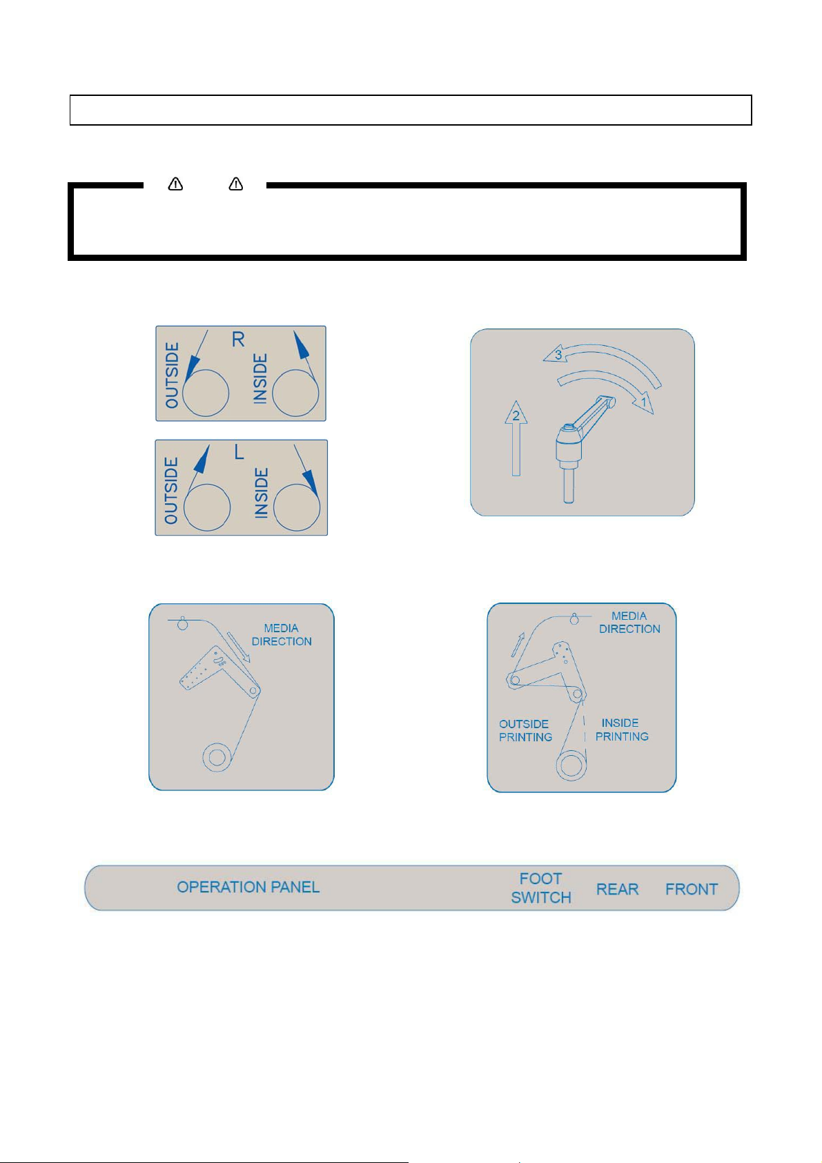
1.3 OPERATION LABELS
The operation labels mentioned below are attached to areas to which attention should be paid.
• Make sure that all labels can be recognized. If text or illustrations are invisible, clean the label.
• When cleaning labels, use a cloth with water or neutral detergent. Do not use a solvent or gasoline.
• If an operation label has been damaged, lost or cannot be recognized, replace the label.
Notes
Foot switch label Roll unit handle label
Front tensioning label
Rear tensioning label
PCB box label
1-2
Page 7

1.4 WEEE REGULATIONS
WEEE regulations
Environmental information
Disposal of your old product
Your product is designed and manufactured with high quality materials and components, which
can be recycled and reused.
When this crossed-out wheeled bin symbol is attached to a product it means the product is
covered by the European Directive 2002/96/EC
Please inform yourself about the local separate collection system for electrical and electronic
products.
Please act according to your local rules and do not dispose of your old products with your normal
household waste. The correct disposal of your old product will help prevent potential negative
consequences for the environment and human health.
1-3
Page 8

This page is intentionally left blank.
1-4
Page 9
2 PRODUCT OVERVIEW
2.1 PART NAMES AND FUNCTIONS
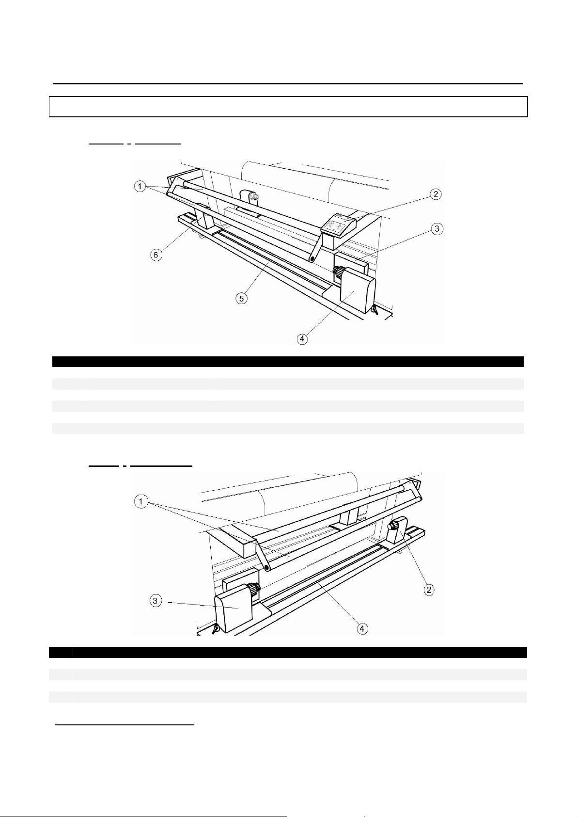
2.1.1 Front / Winder
No Name Function
Front tensioning system Adjust the tension between the print platform and the winding system.
1
Operation panel To control the unwinder winder 100 manually or automatically
2
PCB Box Contains the boards to control the UW/W 100.
3
Motorized roll unit Supports and winds up the roll media.
4
Roll unit bar Supports the roll units.
5
Roll unit Supports the roll media.
6
2.1.2 Rear / Unwinder
(*)
(*)
No Name Function
Rear tensioning system Adjust the tension between the print platform and the unwinding system.
1
Roll unit Supports the roll media.
2
Motorized roll unit Supports and unwinds the roll media.
3
Roll unit bar Supports the roll units.
4
*
On the picture above, the winding system is installed on a Spitfire 65. The position of some parts shall be different when installing the
winding system on a Spitfire 90”, Rockhopper 3, Viper or a ValueJet 1604.
2-1
Page 10
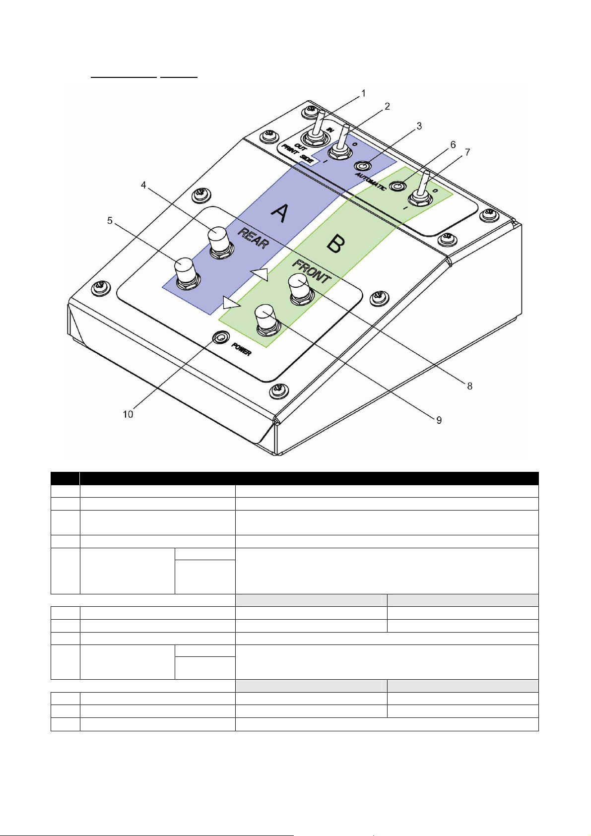
2.1.3 Operation Panel
No. Name Function
A / Part of the operation panel controlling the unwinder 100.
B / Part of the operation panel controlling the winder 100.
1 Print Side Selector
2 Unwinder 100 switch Toggle between Manual (“0”) and Automatic (“I”) mode.
Manual
3 Unwinder 100 LED
Outside printing Inside printing
4 Backwards button Roll-off unwinder Roll-up unwinder
5 Forwards button Roll-up unwinder Roll-off unwinder
6 Winder 100 switch Toggle between Manual (“0”) and Automatic (“I”) mode.
7 Winder 100 LED
Outside printing Inside printing
8 Backwards button Roll-off winder Roll-off winder
9 Forwards button Roll-up winder Roll-up winder
10 Power LED Lightens up if the system is powered ON.
Automatic
Manual
Automatic
In case you loaded media with printed side on the outside select
‘OUT’, otherwise select ‘IN’.
LED lights up when pushing one of the buttons
Motor turns: LED flashes.
Motor is off: LED is out.
Motor accelerates: LED burns continuously.
LED lights up when pushing one of the buttons
Motor turns: LED flashes
Motor is off: LED is out.
2-2
Page 11
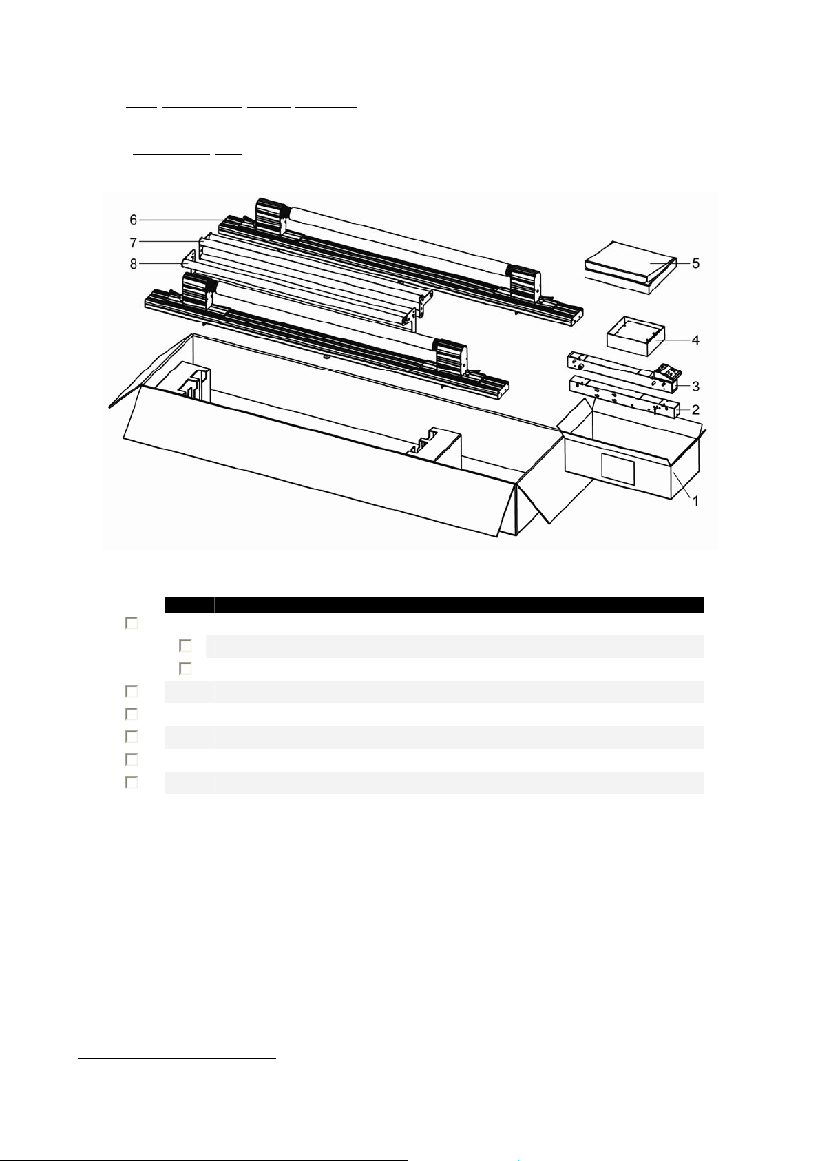
2.2 VERIFYING THE PACKAGED ITEMS
Inspect the unit for damage and check that all necessary parts are present.
• The parts which are not described are buffers to hold the parts in their position and to protect them.
2.2.1 For Rockhopper 3, Spitfire and Viper.
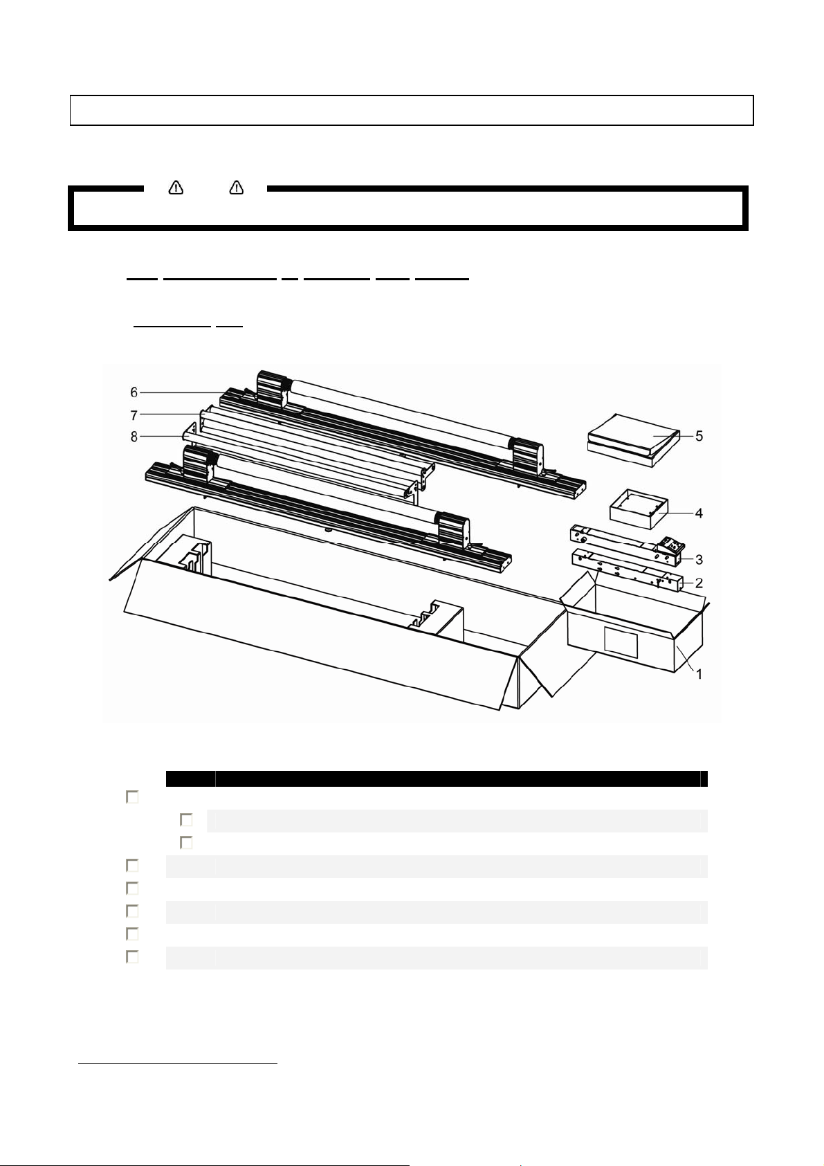
2.2.1.1 Packaging box
Notes
No Part Description Quantity
Box 1: Bracket arms 1
1
2 Left bracket 1
3 Keyboard bracket 1
Box 2 : PCB box 1
4
5
Box 3 : Winder kit
Roll unit bar 2
6
Rear tensioning bar 1
7
Front tensioning bar 1
8
†
†
Please refer to the next page for the contents of this box
1
2-3
Page 12
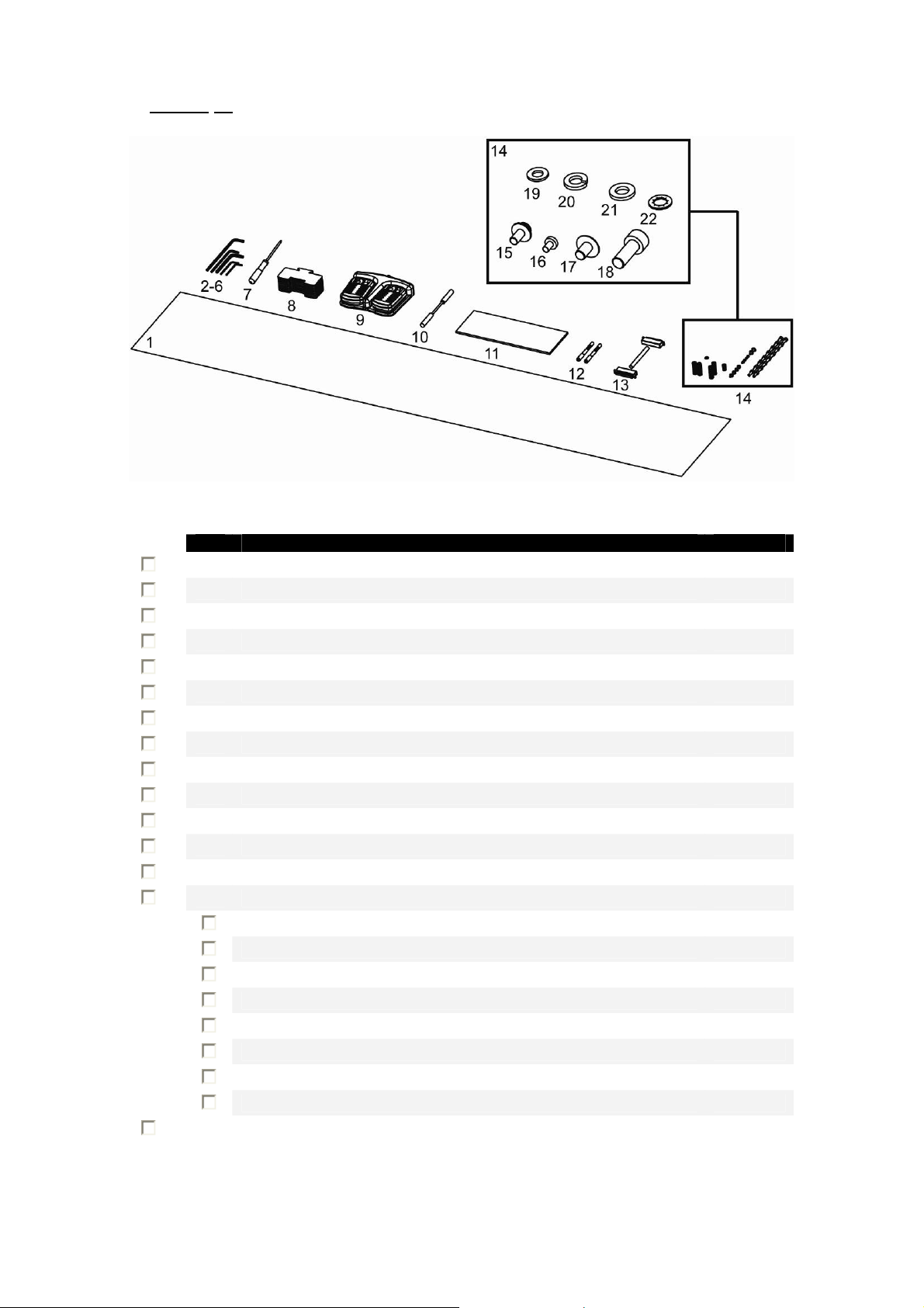
2.2.1.2 Winder kit
No Part Description Quantity
PET adjusting strip 1
1
Hexagon key 2.5 mm 1
2
Hexagon key 3 mm 1
3
Hexagon key 4 mm 1
4
Hexagon key 5 mm 1
5
Hexagon key 6 mm 1
6
Philips screwdriver p2 1
7
Spacer 10
8
Foot switch 1
9
Motor twist cable 1
10
Adjustment plate 1
11
D-lock shafts 2
12
Keyboard cable 1
13
Screw set 1
14
15 Screw M4x10 4
16 Screw M3x5 4
17 Screw M5x8 2
18 Screw M6x16 16
19 Washer M5 4
20 Spring washer M6 16
21 Washer M6 16
22 Lock washer M6 1
User’s Guide 1
23
2-4
Page 13
2.2.2 For ValueJet 1604 series.
2.2.2.1 Packaging box
No Part Description Quantity
Box 1: Bracket arms 1
1
2 Left bracket 1
3 Keyboard bracket 1
Box 2 : PCB box 1
4
5
Box 3 : Winder kit
Roll unit bar 2
6
Rear tensioning bar 1
7
Front tensioning bar 1
8
‡
1
‡
Please refer to the next page for the contents of this box
2-5
Page 14
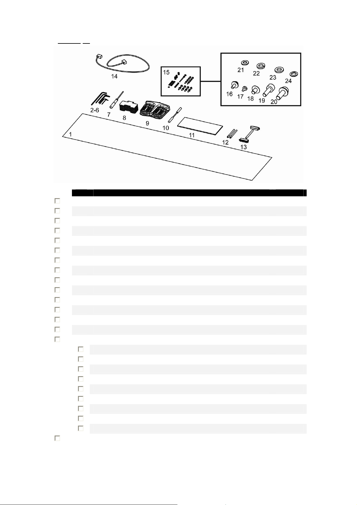
2.2.2.2 Winder kit
.
No Part Description Quantity
PET adjusting strip 1
1
Hexagon key 2.5 mm 1
2
Hexagon key 3 mm 1
3
Hexagon key 4 mm 1
4
Hexagon key 5 mm 1
5
Hexagon key 6 mm 1
6
Philips screwdriver p2 1
7
Spacer 10
8
Foot switch 1
9
Motor twist cable 1
10
Adjustment plate 1
11
Lock shafts 2
12
Keyboard cable 1
13
Power cable (EU + UK) 2
14
Screw set 1
15
16 Screw M4x10 4
17 Screw M3x5 4
18 Screw M5x8 2
19 Screw M6x16 8
20 Self locking screws M6x16 8
21 Synthetic Washer M5 4
22 Spring washer M6 8
23 Washer M6 8
24 Lock washer M6 1
User’s Guide 1
25
2-6
Page 15

3.1 GENERAL SEQUENCE
U
MOUNT THE ROLL UNIT BARS
MOUNT THE BRACKETS FOR THE TENSIONING BARS
INSTALL THE TENSIONING BARS
CALIBRATE THE UNWINDER / WINDER 100
ADJUST THE WEIGHT SUPPORTS UNDER THE ROLL UNIT BARS
3 INSTALLING THE UNIT
NPACK ALL ITEMS
▼
▼
▼
▼
▼
3-1
Page 16

3.2 INSTALL ALL PARTS
3.2.1 Mounting the roll unit bars
Parts and Tools needed
No Description Quantity needed
1 Roll unit bar 2 2
2 Hexagon bolt M6x16 8 8
3 Plain washer M6 8 8
4 Tooth lock washer M6 8 8
5 Hexagon wrench 5 mm 1 1
Procedure
Step 1 : Position the roll unit bars (1) on the printer stand as shown on the image below.
RH3 – SPFR ValueJet
3-2
Page 17

Step 2 : Mount the left side of the bars with the mounting supports to the printer’s stand as indicated on
the image below.
No. Description
1 Plain washer M6
2 Tooth lock washer M6
3 Hexagon bolt M6x12
Step 3 : Check the gap (s) between the adjustable mounting support (1) on the right hand side and the
printer stand and perform the correct action. This has to be done for both roll unit bars. See
below.
No Description
1 Adjustable mounting support
2 Left mounting support
3 Gap between support and printer foot
IF … THEN …
s = 1 or s > 1 mm
s < 1mm
• loosen the 4 screws holding the support on the roll unit bar,
• slide the support against the right side of the printer’s stand,
• mount the support to the printer’s stand and fix the 4 screws holding the support
on the roll unit bar.
• mount the support to the printer’s stand without adjusting.
3-3
Page 18

3.2.2 Mounting the brackets for the tensioning bars
3.2.2.1 On a Spitfire, Rockhopper 3 and Viper
Parts and Tools needed
No Description Quantity
1 Right bracket 1
2 Left bracket 1
3 Hexagon bolt M6x16 8
4 Plain washer M6 8
5 Spring washer M6 8
6 Tooth lock washer M6 1
7 Hexagon wrench 5 mm 1
Instructions
Step 1 : Mount the left and right bracket to the bottom of the X-rail.
Note that the positioning of the left and right bracket is different depending on the size of the
machine.
No Description
1 Left bracket arm
2 Unused holes
3 Left leg of the printer stand
4 Right leg of the printer stand
5 Right bracket arm
Step 2 : Fix the screws of the right bracket.
On the Left Bracket, install 4 screws on the right side and 2 screws on the left side in the center.
Do NOT fix the screws of the left (adjustable) bracket yet.
No Description
1 Hexagon bolt M6x16
2 Spring washer M6
3 Plain washer M6
3-4
Page 19

3.2.2.2 On a ValueJet 1604
Parts and Tools needed
No Description Quantity
1 Right bracket 1
2 Left bracket 1
3 Self locking bolt M6x16 8
4 Tooth lock washer M6 1
5 Hexagon wrench 5 mm 1
Instructions
Before installing the winding system on a ValueJet, it is recommended to loosen screws fixing the printer
from its stand and push it to the rear and tighten the bolts again. This to be sure that the machine is well
positioned.
Step 1 : Screw the self locking bolts half way in.
Notes
Step 2 : Hook the left and right bracket over the four screws and pull.
Step 3 : Tighten the bolts of the right bracket.
3-5
Page 20

3.2.3 Installing the tensioning bars
Parts and Tools needed
No Description Quantity
1 Front tensioning bar 1 1
2 Rear tensioning bar 1 1
3 D-lock type shaft 2 4 Pivot shaft - 2
5 Pan head screw flat M4x10 4 4
6 Philips screwdriver 1 1
7 Hexagon wrench 5 mm 1 1
Procedure
Step 1 : Insert the two shafts (1) in the left (adjustable) bracket at the front and rear.
RH3 & SPFR ValueJet 1604
front rear
Use care when lifting the tensioning bars to avoid bending the bars.
Caution
Step 2 : Position the front tensioning bar (1) between the D-lock shafts of the left and right bracket in such
a way that it fits the corresponding D hole in the plates (2) of the tensioning bars.
–––
Notes
While installing the tensioning bar, push the adjustable shaft in the left bracket, to make insertion of the
front tensioning bar possible.
3-6
Page 21

Step 3 : Fix the front and rear tensioning bar with 4 times an M4x10 screw.
Caution
Be sure to lock the front tensioning bar at both sides with 2 pan head screws. These scre ws have to
be fixed before installing the front tensioning system!
Caution
Be sure to calibrate the complete system before using it. Please refer to the next chapter for this
issue.
Install the remaining screws on the left bracket. Tighten all screws.
Notes
3-7
Page 22

3.2.4 Mounting the PCB Box
Parts and Tools needed
No Description Quantity
1 PCB Box 1
2 Screw M5x8 2
3 Washer M5 4
4 Hexagon wrench 3 mm 1
Procedure
Step 1 : Mount the two screws with each two spacers to the stand.
Step 2 : Place the PCB Box (2) against the stand and slide it with the holes over the screws (1) and push
it downwards until it is fixed.
3-8
Page 23

3.2.5 Connecting the cables.
• Use a power cable that is suitable to the local power specifications when connecting the UW/W 100 to
the power grid.
• If the kit is separately ordered from a printer as an optional item, then a power cable is included in the
UW/W 100 kit
• If the UW/W 100 kit has been delivered with a new printer as a standard in the box item, then the
power cable is located in the printer’s packaging box, not in UW/W 100 packaging box.
Step 1 : Connect the power cable to the power supply connector.
Caution
Step 2 : Check if the all cables of the UW/W are connected to the correct connector (1 to 6). See image
below for the location of the connectors.
Nr Description
1 Power supply connector
2 Front motorized unit connector
3 Rear motorized unit connector
4 Foot switch connector
5 Not used
6 Operation panel connector
Notes
With a small intervention it is possible to reverse your winding direction.
Mount the Motor twist cable between the control box and the front motorized unit cable.
Check if the cable to the operation panel is connected properly on both sides.
Notes
3-9
Page 24

3.3 CALIBRATING THE UW/W 100
3.3.1 Calibrating the rear tensioning system
Parts and Tools needed
Included in kit
No. Description Quantity
1 Synthetic paper strip 1
2 Hexagon wrench 2,5 mm 1
3 Hexagon wrench 3 mm 1
4 Hexagon wrench 4 mm 1
NOT included in kit
No. Description Quantity
1 Tape 1
2 Pencil 1
3.3.1.1 Checking the calibration
The procedure below describes the calibration check of the rear tensioning system. The method to check
the front tensioning system is the same. However, the front and rear tensioning bars use different bars to
complete the calibration.
Procedure :
PART 1 : PREPARING THE SYNTHETIC PAPER STRIP
Step 1 : Put the pressure rollers in the up position.
Step 2 : Go to the back of the machine.
Step 3 : Create a loop with the synthetic paper strip around the upper bar of the rear tension system at
the left side when standing at the back of the printer.
3-10
FRONT REAR
Page 25

Step 4 : Check if the edges of the loop are aligned on each other.
Step 5 : Raise the pressure rollers. Slide the end of the strip (1) under the pressure rollers (4) and move
it to position 1 as shown on the picture below. Lower the pressure rollers.
No Description
1 Synthetic paper strip
2 Paper loop
3 Tensioning bars
4 Pressure rollers
Step 6 : Go to the FRONT SIDE of the printer.
Step 7 : Carefully pull the strip to create some tension.
Caution
• Don’t pull too hard on the strip. This will loosen the tape, resulting in the fact that the loop
becomes longer, leading to a bad calibration check.
• Make sure that you have an equal tension on the left and right of the strip.
3-11
Page 26

PART 2 : DRAWING THE CONTROL LINES
Step 1 : Place the adjustment plate onto the strip and slide it against the pressure rollers.
Step 2 : Draw a line on the strip.
Step 3 : Slide the strip (1) to position 2 as indicated on the image below.
3-12
No Description
1 Synthetic paper strip
2 Paper loop
3 Tensioning bars
4 Pressure rollers
Page 27

Step 4 : Carefully pull the strip to create some tension.
Caution
• Don’t pull too hard on the strip. This will loosen the tape, resulting in the fact that the loop
becomes longer, leading to a bad calibration check.
• Make sure that you have an equal tension on the left and right of the strip.
Step 5 : Place the adjustment plate onto the strip and slide it against the pressure rollers. See image
below.
Step 6 : Draw a line for the second time. The following two situations can be obtained.
Line overlap each other
► well adjusted
► perform the adjustment procedure as described in the next chapter
Line does NOT overlap each other
3-13
Page 28

3.3.1.2 Adjusting the tensioning systems
Introduction
The present topic describes the adjustment of the REAR tensioning system. The procedure to adjust the
front tensioning system is the same.
Procedure
Step 1 : Standing at the REAR SIDE of the unit, remove the cover (1) of the adjustable bracket (3).
Tool : Hexagon wrench 2,5 mm
No Description
1 Cover
2 Screws
3 Adjustable bracket
Step 2 : Loosen (don’t remove) the 4 screws on the side of the adjustable bracket.
Tool : Hexagon wrench 4 mm
No Description
1 Screws
2 Adjustable bracket
3-14
Page 29

Step 3 : Use the 2 screws (1) in the tension bar bracket to adjust the tension system. Referencing the
figures below Line 1 is drawn in Position 1 and Line 2 in drawn in Position 2.
Tool : Hexagon wrench 3 mm
REAR REAR
1 = Adjustment screws
IF Line 2 lays… THEN turn the adjustment screws as follows :
BEFORE line 1 (Case A on image above)
BEHIND line 1 (Case B on image above)
• Make sure to turn both adjustment screws an equal amount of turns.
Caution
Step 4 : Check the calibration again and repeat the adjustment until the lines overlap each other.
3-15
Page 30

3.3.2 Calibrating the front and rear roll unit bars.
3.3.2.1 Introduction
The heights (hL and hR) on both sides of the roll unit bar (2) in relation to the printer stand (1) have to be
adjust with spacers (3) to calibrate a roll unit bar (2),.
FRONT VIEW
No Description
1 Printer stand
2 Roll unit bar
3.3.2.2 Checking the calibration of the roll units
The procedure below describes the calibration check of the FRONT roll unit. The procedure to check the rear
roll unit is the same. In the procedure, line 1 is drawn at the RIGHT side of the printer, line 2 at its LEFT side.
Procedure
ART 1 : PREPARING THE SYNTHETIC PAPER STRIP
P
Step 1 : Put the pressure rollers in the ‘up’ position.
Step 2 : Install an empty core between the roll unit and the motorized roll unit at the front side of the
printer.
Step 3 : Standing in front of the printer, use some tape to create a loop around the core with the synthetic
paper strip.
3 Spacer
No Description
1 Core
Step 4 : Check if the edges of the loop (indicated on the images below) are aligned on each other.
3-16
Page 31

Step 5 : Slide the end of the synthetic paper strip (1) under the pressure rollers (4) in position 1 of the
printer until the synthetic paper strip (1) is a little tensioned.
No Description
1 Synthetic paper strip
2 Loop
3 Core
4 Pressure rollers
Caution
• Don’t pull too hard on the strip. This will loosen the tape, resulting in the fact that the loop
becomes longer, leading to a bad calibration check.
• Make sure that you have an equal tension on the left and right of the strip.
3-17
Page 32

ART 2 : DRAWING THE CONTROL LINES
P
Step 1 : Standing at the front side of the unit, place the adjustment plate onto the strip and position it
against the pressure rollers as indicated on the image below.
Step 2 : Draw a line. See image below.
Step 3 : Slide the strip (1) to position 2 as indicated on the image below.
No Description
1 Synthetic paper strip
2 Loop
3 Core
4 Pressure rollers
3-18
Page 33

Step 4 : Place the adjustment plate onto the strip and slide it against the pressure rollers.
Step 5 : Pull the strip so there is an equal tension.
Caution
• Don’t pull too hard on the strip. This will loosen the tape, resulting in the fact that the loop
becomes longer, leading to a bad calibration check.
• Make sure that you have an equal tension on the left and right of the strip.
Step 6 : Draw a line for the second time. The following two situations can be obtained.
Line overlap each other
► well adjusted
► perform the adjustment procedure as described in the next chapter
Line does NOT overlap each other
3-19
Page 34

3.3.2.3 Adjusting the roll units
Procedure
Step 1 : Use the correct amount of spacers (2) to cover the space between the drawn lines (1).
No Description
1 Drawn lines
2 Spacer
Step 2 : Determine the deviation of the roll unit using the image and table below.
Adjusting the FRONT Units
IF line 2 lays… THEN…
BEFORE line 1 Remove spacers on the left front unit or add spacers on the right front unit.
BEHIND line 1 Add spacers on the left front unit or remove spacers on the right front unit.
Adjusting the REAR Units
IF line 2 lays… THEN…
BEFORE line 1 Add spacers on the left rear unit or remove spacers on the right rear unit.
BEHIND line 1 Remove spacers on the left rear unit or add spacers on the right rear unit.
3-20
Page 35

Step 3 : Insert these spacers (1) at the left or right side (depending on the deviation determined in the
previous step) BETWEEN the roll unit bar (3) and the printer’s stand (2). (See images below)
No Description
1 Spacer
2 Printer’s stand
3 Roll unit bar
Step 4 : Check the calibration of the roll system again and do an adjustment again if necessary.
Step 5 : Now fix the screws of the roll unit bar so the bar doesn’t move anymore.
3-21
Page 36

3.3.3 Adjusting the weight supports under the UW/W 100
Parts and Tools needed
No. Description Quantity
1 Hexagon wrench 3 mm 1
3.3.3.1 Location of the weight supports on a 65” printer
There are 2 weight supports on the UW/W 100 system for a 65” machine, see the images below for their
positions.
FRONT VIEW
No Description
1 Weight support
3.3.3.2 Location of the weight supports on a 90” printer
There are 4 weight supports on the UW/W 100 system for a 90” machine, see the images below for their
positions.
FRONT VIEW
No Description
1 Weight support
3-22
Page 37

3.3.3.3 Adjusting the weight supports
• Don’t turn the weight supports with force when they reach the floor!
Instructions
Lower the weight supports of the UW/W 100 till they reach the floor. A hexagon wrench 6 mm can be used
as indicated below.
Caution
No Description
1 Hexagon wrench 6 mm
2 Turning direction to lower the support
3-23
Page 38

This page is intentionally left blank.
3-24
Page 39

4 OPERATING THE SYSTEM
4.1 TURNING THE POWER ON / OFF
The switch in located on the power supply box.
Its status is marked with “O” and “I”.
“I” Switched ON Power LED on control panel of winding system will light up
“O” Switched OFF Power LED on control panel of winding system will not be lid.
4-1
Page 40

4.2 LOADING ROLL MEDIA
Please follow the procedure below to install and load roll media.
Step 1 : Make sure the printer and Unwinder/Winder 100 are switched ON.
Step 2 : Raise the pressure rollers of the printer.
Step 3 : Open the front cover
Step 4 : Make sure both unwinder (REAR) and winder (FRONT) unit are set to MANUAL mode.
Step 5 : Consider the specifications of the printer before loading media:
Maximum loading capacity
Maximum media width
For ValueJet 1604
For Spitfire 65”, Rockhopper 3 65” and Viper 65”
For Spitfire 90”, Rockhopper 3 90” and Viper 90”
Minimum media width
For ValueJet 1604
For Spitfire 65”, Rockhopper 3 65” and Viper 65”
For Spitfire 90”, Rockhopper 3 90” and Viper 90”
Inner core diameter
Step 6 : Remove the packaging of the media roll.
Step 7 : Check whether the media is inside or outside printable. This affects the installation method on the
unwinder at the rear of the machine.
Metrical Imperial
100 kg 220 lb
1625 mm
1653 mm
2280 mm
1000 mm
210 mm
210 mm
63.98 in
65.07 in
89.76 in
39.37 in
8.27 in
8.27 in
50.8 mm or 76.2 mm 2 in or 3 in
Step 8 : Install the media between the two roll units at the back of the machine. Loosen the handles to
move the roll units left and right.
4-2
Page 41

Step 9 : Be sure that the media is loaded centrally. This to be sure that the media is wound up straight.
This can be easily checked by the yellow labels on the winding rails. Be sure to mount the left
and right roll unit on the same distance from the 0I0 label.
Step 10 : Install an empty core between the front roll units.
a. Make sure the core is longer than the media width.
b. Load it centrally as described in previous step
Step 11 : Use the foot-switch to release some media at the rear.
Step 12 : Load media through the rear tensioning bar, over the print platform, under the pressure rollers as
pictured below.
Outside printable Inside Printable
Roll unit
1
Media roll
2
Rear tensioning bar
3
Print platform and
4
pressure rollers
4-3
Page 42

Step 13 : Take the media on the front of the printer and pull until the rear tensioning system gently hits the
Step 14 : Lower the pressure rollers
Step 15 : Set the unwinder (REAR) unit to AUTOMATIC.
Be sure to make the correct settings on the control panel of the winding system. OUTSIDE or INSIDE
Step 16 : Forward the media until you can stick it to the core installed between the front roll units.
back of the machine. This to become an equal tension.
The rear tensioning system will go to its initial position.
Notes
Make sure to have an equal tension on both sides of the media.
Roll unit
1
Empty core
2
Front tensioning bar
3
To ease the winding up of the media on the front core, it is permitted to cut the media in a V-shape.
HINT
Step 17 : Tighten the media straight to the core with tape.
Step 18 : After closing the front cover, the media initialize will start.
Step 19 : Set the winder (FRONT) unit to ACTIVE. The front tensioning system will be activated.
Step 20 : Installation of the media is completed.
Notes
With a small intervention it is possible to reverse your winding direction. Mount the twist cable between the
control box and the front motorized unit cable.
4-4
Page 43

Page 44

 Loading...