

Page 1

Version 3.1
March 2007
DocuColor 8000/7000
Operator
Manual
Page 2

Prepared by:
Xerox Corporation
Global Knowledge & Language Services
800 Phillips Road
Building 845
Webster, New York 14580
©
Copyright 2007 by Xerox Corporation. All Rights Reserved.
Copyright protection claimed includes all forms and matters of copyrighted material and information now allowed by statutory or judicial law or
hereinafter granted, including without limitation, material generated from the software programs that are displayed on the screen such as styles,
templates, icons, screen displays, looks, etc.
®
Xerox
, Xerox Canada Ltd®, Xerox Limited®, and all Xerox product names and product numbers mentioned in this publication are trademarks
of XEROX CORPORATION. Copyright protection claimed includes all forms and matters of copyrightable material and information now allowed
by statutory or judicial law or hereinafter granted, including without limitations, material generated from the software programs which are
displayed on the screen such as styles, templates, icons, screen displays looks, etc. Other company brands and product names may be
trademarks or registered trademarks of the respective companies and are also acknowledged.
While every care has been taken in the preparation of this material, no liability will be accepted by Xerox Corporation arising out of any
inaccuracies or omissions.
Changes are periodically made to this document. Changes, technical innacuracies, and typographic errors will be corrected in subsequent
editions.
Page 3

Table of contents
Conventions vii
Symbols . . . . . . . . . . . . . . . . . . . . . . . . . . . . . . . . . . . . . . . . . . . vii
Safety notices ix
Electrical safety. . . . . . . . . . . . . . . . . . . . . . . . . . . . . . . . . . . . . . .ix
Disconnect device. . . . . . . . . . . . . . . . . . . . . . . . . . . . . . . . . . x
Laser safety . . . . . . . . . . . . . . . . . . . . . . . . . . . . . . . . . . . . . . . . .xi
North America . . . . . . . . . . . . . . . . . . . . . . . . . . . . . . . . . . . . .xi
Europe (EU) and other markets . . . . . . . . . . . . . . . . . . . . . . xii
Safety standards. . . . . . . . . . . . . . . . . . . . . . . . . . . . . . . . . . . . . xii
North America . . . . . . . . . . . . . . . . . . . . . . . . . . . . . . . . . . . . xii
Europe (EU) and other markets . . . . . . . . . . . . . . . . . . . . . . xii
Maintenance safety. . . . . . . . . . . . . . . . . . . . . . . . . . . . . . . . . . . xiii
Operational safety. . . . . . . . . . . . . . . . . . . . . . . . . . . . . . . . . . . .xiii
Ozone safety. . . . . . . . . . . . . . . . . . . . . . . . . . . . . . . . . . . . . . . .xiv
Notices xv
Radio frequency emissions. . . . . . . . . . . . . . . . . . . . . . . . . . . . . xv
FCC in the USA . . . . . . . . . . . . . . . . . . . . . . . . . . . . . . . . . . xv
In Canada (ICES-003) . . . . . . . . . . . . . . . . . . . . . . . . . . . . . xv
Regulatory information for RFID. . . . . . . . . . . . . . . . . . . . . .xvi
Safety extra low voltage approval. . . . . . . . . . . . . . . . . . . . . . . .xvi
Certifications in Europe. . . . . . . . . . . . . . . . . . . . . . . . . . . . . . . .xvi
It’s illegal in the USA . . . . . . . . . . . . . . . . . . . . . . . . . . . . . . . . . xviii
It’s illegal in Canada . . . . . . . . . . . . . . . . . . . . . . . . . . . . . . . . . . xx
Environmental notices for Canada . . . . . . . . . . . . . . . . . . . . . . .xxi
Product recycling and disposal . . . . . . . . . . . . . . . . . . . . . . . . . xxii
North America. . . . . . . . . . . . . . . . . . . . . . . . . . . . . . . . . . . xxii
European union . . . . . . . . . . . . . . . . . . . . . . . . . . . . . . . . . xxiii
Other countries . . . . . . . . . . . . . . . . . . . . . . . . . . . . . . . . . . xxiii
DocuColor 8000/7000 Operator Manual
i
Page 4

Table of contents
Overview 1-1
Identifying the external components . . . . . . . . . . . . . . . . . . . . . 1-2
Ecology Module . . . . . . . . . . . . . . . . . . . . . . . . . . . . . . . . . 1-5
Electrical Module . . . . . . . . . . . . . . . . . . . . . . . . . . . . . . . . 1-6
Dry Ink/Toner Waste Bottle . . . . . . . . . . . . . . . . . . . . . . . . . 1-7
Ground Fault Indicator (GFI) circuit breakers . . . . . . . . . . . 1-8
User Interface (UI) . . . . . . . . . . . . . . . . . . . . . . . . . . . . . . . . . 1-10
Control Panel . . . . . . . . . . . . . . . . . . . . . . . . . . . . . . . . . . . . . 1-12
Job Status . . . . . . . . . . . . . . . . . . . . . . . . . . . . . . . . . . . . . 1-14
Power Saver . . . . . . . . . . . . . . . . . . . . . . . . . . . . . . . . . . . 1-17
Language . . . . . . . . . . . . . . . . . . . . . . . . . . . . . . . . . . . . . 1-17
Access . . . . . . . . . . . . . . . . . . . . . . . . . . . . . . . . . . . . . . . 1-18
Machine Status . . . . . . . . . . . . . . . . . . . . . . . . . . . . . . . . . 1-18
Machine Details tab . . . . . . . . . . . . . . . . . . . . . . . . . . . . . 1-20
Maintenance tab . . . . . . . . . . . . . . . . . . . . . . . . . . . . . . . . 1-21
Help . . . . . . . . . . . . . . . . . . . . . . . . . . . . . . . . . . . . . . . . . 1-24
Audio tones. . . . . . . . . . . . . . . . . . . . . . . . . . . . . . . . . . . . 1-24
Alert screens. . . . . . . . . . . . . . . . . . . . . . . . . . . . . . . . . . . 1-25
Identifying the internal components . . . . . . . . . . . . . . . . . . . . 1-26
Serial number label. . . . . . . . . . . . . . . . . . . . . . . . . . . . . . 1-26
Paper Transport drawer . . . . . . . . . . . . . . . . . . . . . . . . . . 1-26
Transport Module . . . . . . . . . . . . . . . . . . . . . . . . . . . . . . . 1-27
Paper path in the digital press . . . . . . . . . . . . . . . . . . . . . 1-28
Exit Module . . . . . . . . . . . . . . . . . . . . . . . . . . . . . . . . . . . . 1-29
Relocating the digital press. . . . . . . . . . . . . . . . . . . . . . . . . . . 1-30
Customer documentation updates . . . . . . . . . . . . . . . . . . . . . 1-30
Paper and paper trays 2-1
Recommended Materials List (RML) . . . . . . . . . . . . . . . . . . . . 2-1
Paper handling . . . . . . . . . . . . . . . . . . . . . . . . . . . . . . . . . . . . . 2-1
Paper trays . . . . . . . . . . . . . . . . . . . . . . . . . . . . . . . . . . . . . . . . 2-4
Paper guidelines . . . . . . . . . . . . . . . . . . . . . . . . . . . . . . . . . 2-5
Curl . . . . . . . . . . . . . . . . . . . . . . . . . . . . . . . . . . . . . . . . . . . 2-6
Paper specifications . . . . . . . . . . . . . . . . . . . . . . . . . . . . . . 2-7
Tray capacity. . . . . . . . . . . . . . . . . . . . . . . . . . . . . . . . . . . . 2-8
Duplexing . . . . . . . . . . . . . . . . . . . . . . . . . . . . . . . . . . . . . . 2-8
Transparency guidelines . . . . . . . . . . . . . . . . . . . . . . . . . . . 2-8
Tabbed inserts. . . . . . . . . . . . . . . . . . . . . . . . . . . . . . . . . . . 2-9
Drilled paper . . . . . . . . . . . . . . . . . . . . . . . . . . . . . . . . . . . 2-10
Simplex Print Jobs . . . . . . . . . . . . . . . . . . . . . . . . . . . 2-10
Duplex Print Jobs . . . . . . . . . . . . . . . . . . . . . . . . . . . . 2-10
ii
DocuColor 8000/7000 Operator Manual
Page 5

Table of contents
Letterhead. . . . . . . . . . . . . . . . . . . . . . . . . . . . . . . . . . . . . 2-11
Nonstandard size paper . . . . . . . . . . . . . . . . . . . . . . . . . . 2-11
Auto Tray Switching . . . . . . . . . . . . . . . . . . . . . . . . . . . . . . . . 2-12
Auto Paper Selection . . . . . . . . . . . . . . . . . . . . . . . . . . . . . . . 2-12
Loading paper. . . . . . . . . . . . . . . . . . . . . . . . . . . . . . . . . . . . . 2-13
Paper weight conversion tables . . . . . . . . . . . . . . . . . . . . . . . 2-16
Specific weight conversion . . . . . . . . . . . . . . . . . . . . . . . . 2-16
Weight conversion ranges . . . . . . . . . . . . . . . . . . . . . . . . 2-17
Accessories 3-1
Trays 3 and 4 (Second Feeder Module) . . . . . . . . . . . . . . . . . . 3-1
Identifying the parts. . . . . . . . . . . . . . . . . . . . . . . . . . . . . . . 3-2
Paper path . . . . . . . . . . . . . . . . . . . . . . . . . . . . . . . . . . . . . 3-3
Paper guidelines . . . . . . . . . . . . . . . . . . . . . . . . . . . . . . . . . 3-4
Paper Specifications . . . . . . . . . . . . . . . . . . . . . . . . . . . . . 3-5
Loading paper. . . . . . . . . . . . . . . . . . . . . . . . . . . . . . . . . . . 3-6
Paper trays air adjustment . . . . . . . . . . . . . . . . . . . . . . . . . 3-7
Jam clearance . . . . . . . . . . . . . . . . . . . . . . . . . . . . . . . . . . 3-8
Physical characteristics. . . . . . . . . . . . . . . . . . . . . . . . . . . . 3-8
Size . . . . . . . . . . . . . . . . . . . . . . . . . . . . . . . . . . . . . . . . 3-8
Weight. . . . . . . . . . . . . . . . . . . . . . . . . . . . . . . . . . . . . . 3-8
Floor space requirements . . . . . . . . . . . . . . . . . . . . . . . 3-8
High Capacity Stacker 80 . . . . . . . . . . . . . . . . . . . . . . . . . . . . . 3-9
Identifying the parts. . . . . . . . . . . . . . . . . . . . . . . . . . . . . . 3-11
Control panel. . . . . . . . . . . . . . . . . . . . . . . . . . . . . . . . 3-11
Cooling fan . . . . . . . . . . . . . . . . . . . . . . . . . . . . . . . . . 3-13
Paper path . . . . . . . . . . . . . . . . . . . . . . . . . . . . . . . . . . . . 3-15
Top Tray . . . . . . . . . . . . . . . . . . . . . . . . . . . . . . . . . . . 3-15
Stacker Tray . . . . . . . . . . . . . . . . . . . . . . . . . . . . . . . . 3-15
Bypass . . . . . . . . . . . . . . . . . . . . . . . . . . . . . . . . . . . . 3-15
Paper guidelines . . . . . . . . . . . . . . . . . . . . . . . . . . . . . . . . 3-16
Recommended baseline/centerline. . . . . . . . . . . . . . . 3-16
Paper specifications . . . . . . . . . . . . . . . . . . . . . . . . . . . . . 3-17
Unloading the Stacker Tray. . . . . . . . . . . . . . . . . . . . . . . . 3-18
Selecting Features . . . . . . . . . . . . . . . . . . . . . . . . . . . . . . 3-19
How to Enable Automatic Output Switching . . . . . . . . 3-19
Using a DFA Finishing Device . . . . . . . . . . . . . . . . . . . . . 3-20
Jam clearance . . . . . . . . . . . . . . . . . . . . . . . . . . . . . . . . . 3-20
Clear Bypass area jam . . . . . . . . . . . . . . . . . . . . . . . . 3-21
. . . . . . . Clear Top Tray and Stacker Tray paper jams3-22
Maintenance . . . . . . . . . . . . . . . . . . . . . . . . . . . . . . . . . . . 3-22
Problem Solving . . . . . . . . . . . . . . . . . . . . . . . . . . . . . . . . 3-23
DocuColor 8000/7000 Operator Manual
iii
Page 6

Table of contents
Loss of Power . . . . . . . . . . . . . . . . . . . . . . . . . . . . . . . 3-24
High Capacity Stacker Stapler 80 (HCSS80) . . . . . . . . . . . . . 3-25
Identifying HCSS80 Parts . . . . . . . . . . . . . . . . . . . . . . . . . 3-25
Control Panel . . . . . . . . . . . . . . . . . . . . . . . . . . . . . . . 3-26
Electrical/environmental requirements . . . . . . . . . . . . . . . 3-27
Paper stock specifications . . . . . . . . . . . . . . . . . . . . . . . . 3-27
Paper Path . . . . . . . . . . . . . . . . . . . . . . . . . . . . . . . . . 3-29
Using the HCSS80 . . . . . . . . . . . . . . . . . . . . . . . . . . . . . . 3-30
Hints and tips . . . . . . . . . . . . . . . . . . . . . . . . . . . . . . . 3-30
Stapling Hints . . . . . . . . . . . . . . . . . . . . . . . . . . . . . . . 3-30
Paper specifications for stapling . . . . . . . . . . . . . . . . . 3-31
Staple Positions . . . . . . . . . . . . . . . . . . . . . . . . . . . . . 3-32
Stapling capacity for different paper types and weights . . 3-34
Unloading the HCSS80. . . . . . . . . . . . . . . . . . . . . . . . . . . 3-34
Jam Clearance . . . . . . . . . . . . . . . . . . . . . . . . . . . . . . . . . 3-35
Ordering and Loading Staples . . . . . . . . . . . . . . . . . . . . . 3-36
HCSS80 Maintenance . . . . . . . . . . . . . . . . . . . . . . . . . . . 3-37
Cleaning the HCSS80. . . . . . . . . . . . . . . . . . . . . . . . . 3-37
Problem Solving . . . . . . . . . . . . . . . . . . . . . . . . . . . . . . . . 3-37
Loss of Power . . . . . . . . . . . . . . . . . . . . . . . . . . . . . . . 3-40
Common Stacker/Stapler (CSS) . . . . . . . . . . . . . . . . . . . . . . . 3-41
Identifying CSS Parts . . . . . . . . . . . . . . . . . . . . . . . . . . . . 3-41
Control Panel . . . . . . . . . . . . . . . . . . . . . . . . . . . . . . . 3-42
Electrical/environmental requirements . . . . . . . . . . . . . . . 3-43
Paper stock specifications . . . . . . . . . . . . . . . . . . . . . . . . 3-43
Paper Path . . . . . . . . . . . . . . . . . . . . . . . . . . . . . . . . . 3-45
Using the stacker/stapler . . . . . . . . . . . . . . . . . . . . . . . . . 3-46
Hints and tips . . . . . . . . . . . . . . . . . . . . . . . . . . . . . . . 3-46
Stapling Hints . . . . . . . . . . . . . . . . . . . . . . . . . . . . . . . 3-46
Paper specifications for stapling . . . . . . . . . . . . . . . . . 3-47
Staple Positions . . . . . . . . . . . . . . . . . . . . . . . . . . . . . 3-48
Stapling capacity for different paper types and weights . . 3-50
Unloading the stacker/stapler . . . . . . . . . . . . . . . . . . . . . . 3-50
Jam Clearance . . . . . . . . . . . . . . . . . . . . . . . . . . . . . . . . . 3-51
Ordering and Loading Staples . . . . . . . . . . . . . . . . . . . . . 3-52
Stacker/stapler Maintenance. . . . . . . . . . . . . . . . . . . . . . . 3-53
Cleaning the stacker/stapler . . . . . . . . . . . . . . . . . . . . 3-53
Problem Solving . . . . . . . . . . . . . . . . . . . . . . . . . . . . . . . . 3-53
Loss of Power . . . . . . . . . . . . . . . . . . . . . . . . . . . . . . . 3-56
iv
Problem solving 4-1
General problems . . . . . . . . . . . . . . . . . . . . . . . . . . . . . . . . . . . 4-1
DocuColor 8000/7000 Operator Manual
Page 7

Table of contents
Jam clearance . . . . . . . . . . . . . . . . . . . . . . . . . . . . . . . . . . . . . 4-6
Paper tray jams. . . . . . . . . . . . . . . . . . . . . . . . . . . . . . . . . . 4-7
Upper Transport Area jam . . . . . . . . . . . . . . . . . . . . . . . . . 4-8
Transport Module jams . . . . . . . . . . . . . . . . . . . . . . . . . . . . 4-9
Exit Module jams . . . . . . . . . . . . . . . . . . . . . . . . . . . . . . . 4-11
Right/left door paper path jams. . . . . . . . . . . . . . . . . . . . . 4-12
Jam clearance with 2-sided printing . . . . . . . . . . . . . . 4-14
Fault Codes . . . . . . . . . . . . . . . . . . . . . . . . . . . . . . . . . . . . . . 4-15
Technical Data 5-1
Digital Press Specifications. . . . . . . . . . . . . . . . . . . . . . . . . . . . 5-1
Electrical Power . . . . . . . . . . . . . . . . . . . . . . . . . . . . . . . . . 5-1
Specifications . . . . . . . . . . . . . . . . . . . . . . . . . . . . . . . . 5-1
Power Consumption . . . . . . . . . . . . . . . . . . . . . . . . . . . 5-1
Warm-up Time . . . . . . . . . . . . . . . . . . . . . . . . . . . . . . . 5-1
First Print Out Time. . . . . . . . . . . . . . . . . . . . . . . . . . . . 5-1
Environmental Requirements . . . . . . . . . . . . . . . . . . . . . . . 5-2
Ambient Temperature and Humidity . . . . . . . . . . . . . . . 5-2
Altitude . . . . . . . . . . . . . . . . . . . . . . . . . . . . . . . . . . . . . 5-2
Illumination . . . . . . . . . . . . . . . . . . . . . . . . . . . . . . . . . . 5-2
Noise Levels . . . . . . . . . . . . . . . . . . . . . . . . . . . . . . . . . 5-3
Ozone Emissions . . . . . . . . . . . . . . . . . . . . . . . . . . . . . 5-3
Dust. . . . . . . . . . . . . . . . . . . . . . . . . . . . . . . . . . . . . . . . 5-3
Capabilities . . . . . . . . . . . . . . . . . . . . . . . . . . . . . . . . . . . . . 5-4
Tray Capacity . . . . . . . . . . . . . . . . . . . . . . . . . . . . . . . . 5-4
Throughput . . . . . . . . . . . . . . . . . . . . . . . . . . . . . . . . . . 5-4
Print Rates . . . . . . . . . . . . . . . . . . . . . . . . . . . . . . . . . . 5-5
Physical Characteristics . . . . . . . . . . . . . . . . . . . . . . . . . . . 5-6
Digital Press Size . . . . . . . . . . . . . . . . . . . . . . . . . . . . . 5-6
Digital Press Weight . . . . . . . . . . . . . . . . . . . . . . . . . . . 5-6
Floor Space Requirements . . . . . . . . . . . . . . . . . . . . . . 5-6
Metric Conversion Chart . . . . . . . . . . . . . . . . . . . . . . . . . . . . . . 5-7
Maintenance 6-1
Cleaning procedures. . . . . . . . . . . . . . . . . . . . . . . . . . . . . . . . . 6-1
Cleaning the digital press . . . . . . . . . . . . . . . . . . . . . . . . . . 6-1
Cleaning the UI Touch Screen . . . . . . . . . . . . . . . . . . . . . . 6-2
Cleaning the Charge Corotrons . . . . . . . . . . . . . . . . . . . . . 6-2
Cleaning the Second Transport and Fusing areas . . . . . . 6-10
Cleaning the paper path . . . . . . . . . . . . . . . . . . . . . . . . . . 6-16
Replacing Consumable Supplies . . . . . . . . . . . . . . . . . . . . . . 6-19
DocuColor 8000/7000 Operator Manual
v
Page 8

Table of contents
Replacing a Dry Ink/Toner Cartridge. . . . . . . . . . . . . . . . . 6-20
Adding Fuser Oil . . . . . . . . . . . . . . . . . . . . . . . . . . . . . . . . 6-23
Changing the Waste Dry Ink/Toner Bottle. . . . . . . . . . . . . 6-25
Replacing a Charge Corotron . . . . . . . . . . . . . . . . . . . . . . 6-27
When to replace a charge corotron. . . . . . . . . . . . . . . 6-27
Which charge corotron to replace. . . . . . . . . . . . . . . . 6-27
Banding samples . . . . . . . . . . . . . . . . . . . . . . . . . . . . 6-28
Replacing the Fuser Web . . . . . . . . . . . . . . . . . . . . . . . . . 6-31
Calling for Service. . . . . . . . . . . . . . . . . . . . . . . . . . . . . . . . . . 6-35
Consumable Supplies. . . . . . . . . . . . . . . . . . . . . . . . . . . . . . . 6-37
vi
DocuColor 8000/7000 Operator Manual
Page 9
Symbols
Conventions
Standardized conventions have been used in this manual to assist
you in visually locating and identifying information quickly.
CAUTION: This symbol alerts you to an action that may cause
damage to hardware, software, or result in the loss of data.
WARNING: Warnings mark alert users to areas of the machine
where there is a possibility of personal injury.
WARNING: This symbol identifies an area on the machine that is
HOT and should not be touched.
WARNING: This symbol indicates a laser is being used in the
machine and alerts you to refer to the appropriate safety
information.
TIP: This symbol identifies information that is being emphasized
and is important for you to remember.
DocuColor 8000/7000 Operator Manual
vii
Page 10

Conventions
The 1 2 3... symbol indicates the beginning of a task or work
process you should use to complete a procedure and is followed
by the first step of a numbered procedure, task, or work process.
NOTE: This symbol calls your attention to information that is
helpful, but not essential to compl e te a procedure or task.
viii
DocuColor 8000/7000 Operator Manual
Page 11
Electrical safety
Safety notices
This Xerox product and the recommended supplies are designed
and tested to meet strict safety requirements. These include
safety agency approval and compliance to established
environmental standards. Please read the following instructions
carefully before operating the product, and refer to them as
needed to ensure the continued safe operation of your product.
TIP: The safety testing and performance of this product have
been verified using Xerox materials only.
WARNING: Any unauthorized alteration, which may include the
addition of new functions or connection of external devices, may
impact the product certification. Please contact your authorized
local dealer for more information.
• Use only the power cord supplied with this equipment.
• Plug the power cord directly into a correctly grounded
electrical outlet. Do not use an extension cord. If you do not
know whether or not an outlet is grounded, consult a qualified
electrician.
• Do not use a ground adapter plug to connect this equipment to
an electrical outlet that lacks a ground connection terminal.
WARNING: You may incur a severe electrical shock if the outlet is
not grounded correctly.
• Do not place the machine where people may step or trip on the
power cord. Do not place objects on the power cord.
• Do not override or disable electrical or mechanical interlocks.
• Do not obstruct the ventilation openings. These openings
prevent overheating of the machine.
DocuColor 8000/7000 Operator Manual
ix
Page 12

Safety notices
Disconnect device
WARNING: Never push objects of any kind into slots or openings
on this equipment. Making a contact with a voltage point or
shorting out a part may result in fire or electrical shock.
If any of the following conditions occur, immediately switch off the
power to the machine and disconnect the power cord from the
electrical outlet. Call an authorized Xerox service representative
to correct the problem.
• The machine emits unusual noises or odors.
• The power cord is damaged or frayed.
• A wall panel circuit breaker, fuse, or other safety device is
tripped.
• Liquid is spilled into the press.
• The machine is exposed to water.
• Any part of the machine is damaged.
The power cable is the disconnect device for this equipment and is
attached to the back of the machine as a plug-in device. To
remove all electrical power from the machine, disconnect the
power cable from the electrical outlet.
WARNING: This product must be connected to a protective earth
current.
x
DocuColor 8000/7000 Operator Manual
Page 13

Laser safety
North America
Safety notices
This product complies with safety standards and is certified as a
Class 1 Laser product under the Center for Devices and
Radiological Health (CDRH) of the United States Food and Drug
Administration (FDA) implemented regulations for laser
products. This product complies with FDA 21 CFR 1940.10 and
1040.11 except for deviations pursuant to Laser Notice No. 50,
dated July 26, 2001. These regulations apply to laser products
marketed in the United States. The label on the machine indicates
compliance with CDRH regulations and must be attached to laser
products marketed in the United States. This product does not
emit hazardous laser radiation.
CAUTION: Use of controls or adjustments or performance of
procedures other than those specified herein may result in
hazardous exposure of laser light.
Since radiation emitted inside this product is completely confined
within the protective housing and external covers, the laser beam
cannot escape from the machine during any phase of the user
operation.
This product contains laser warning labels. These labels are
intended for use by the Xerox Service Representative and are
placed on or near panels or shields that require special tools for
removal. Do not remove any of the panels. There are no operator
serviceable areas in these covers.
DocuColor 8000/7000 Operator Manual
xi
Page 14

Safety notices
Europe (EU) and other markets
This product complies with IEC’s safety standard 60825-1 (Edition
1.2) issued August 2001.
The equipment complies with laser product performance
standards set by governmental, national, and international
agencies as a Class 1 Laser Product. It does not emit hazardous
radiation as the beam is totally enclosed during all phases of
customer operation and maintenance.
CAUTION: Use of controls or adjustments or performance of
procedures other than those specified herein may result in
hazardous radiation exposure.
This product contains laser warning labels. These labels are
intended for use by the Xerox Service Representative and are
placed on or near panels or shields that require special tools for
removal. Do not remove any of the panels. There are no operator
serviceable areas inside these covers.
If you need additional safety information concerning the product or
Xerox supplied materials, you may call the following number:
Safety standards
North America
Europe (EU) and other markets
+44 (0) 1707 353434
This Xerox product is safety certified by Underwriters Laboratories
Incorporated to Standards UL60950-1 (first edition), and CSA
International CAN/CSA C22.2 No. 60950-1-03 (First Edition).
This Xerox product is Safety Certified by NEMKO to publication
IEC60950-1 (2001) First Edition.
xii
DocuColor 8000/7000 Operator Manual
Page 15

Maintenance safety
Safety notices
• Do not attempt any maintenance procedure that is not
specifically described in the documentation supplied with your
product.
• Do not use aerosol cleaners. The use of supplies that are not
approved may cause poor performance of the press and could
create a dangerous condition.
• Use the supplies and cleaning materials only as directed in
this manual. Keep all materials out of the reach of children.
• Do not remove the covers or guards that are fastened with
screws. There are no parts behind these covers that you can
maintain or service.
Do not perform any maintenance procedures unless you have
been trained to do them by a Xerox representative, or unless a
procedure is specifically described in one of the manuals included
with your press.
Operational safety
Your Xerox equipment and supplies were designed and tested to
meet strict safety requirements. These include safety agency
examination, approval, and compliance with established
environmental standards.
Your attention to the following safety guidelines will help ensure
the continued safe operation of your product:
• Use the materials and supplies specifically designed for your
product. The use of unsuitable materials may result in poor
performance of the machine and possibly a hazardous
situation.
• Follow all warnings and instructions that are marked on or
supplied with the machine.
• Place the machine in a room that provides adequate space for
ventilation and servicing.
• Place the machine on a level, solid surface (not on a thick pile
carpet) that has adequate strength to support the weight of the
machine.
• Do not attempt to move the machine. A leveling device that
was lowered when your machine was installed may damage
the carpet or floor.
• Do not set up the machine near a heat source.
• Do not set up the machine in direct sunlight.
DocuColor 8000/7000 Operator Manual
xiii
Page 16

Safety notices
Ozone safety
• Do not set up the machine in line with the cold air flow from an
air conditioning system.
• Do not place containers of coffee or other liquid on the
machine.
• Do not block or cover the slots and openings on the machine.
• Do not attempt to override any electrical or mechanical
interlock devices.
WARNING: Be careful when working in areas identified with this
warning symbol. These areas may be very hot and should not be
touched.
If you need any additional safety information concerning the
machine or materials, contact your Xerox representative.
This product produces ozone during normal operation. The ozone
is heavier than air, and the quantity is dependent on print volume.
Providing the correct environmental parameters, as specified in
the Xerox installation procedures, ensures that concentration
levels meet safe limits.
If you need additional information about ozone, request the Xerox
publication, OZONE by calling 1-800-828-6571 in the USA. For a
French language version, call 1-800-828-6571 in the USA, then
press 2.
xiv
DocuColor 8000/7000 Operator Manual
Page 17
Notices
Radio frequency emiss i ons
FCC in the USA
This equipment has been tested and found to comply with the
limits for a Class A digital device, pursuant to Part 15 of the
Federal Communications Commission (FCC) Rules. These limits
are designed to provide reasonable protection against harmful
interference when the equipment is operated in a commercial
environment. This equipment generates, uses, and can radiate
radio frequency energy and, if not installed and used in
accordance with the instruction manual, may cause harmful
interference to radio communications. Operation of this equipment
in a residential area is likely to cause harmful interference in which
case the user will be required to correct the interference at his/her
own expense.
Changes or modifications to this equipment not specifically
approved by the Xerox Corporation may void the user’s authority
to operate this equipment.
WARNING: Shielded cables must be used with this equipment to
maintain compliance with FCC regulations.
In Canada (ICES-003)
This Class “A” digital apparatus complies with Canadian ICES-
003.
Cet appareil numérique de la classe “A” est conforme á la norme
NMB-003 du Canada.
DocuColor 8000/7000 Operator Manual
xv
Page 18
Notices
Regulatory information for RFID
This product generates 13.56 MHz using an Inductive Loop
System as a Radio Frequency IDentification system device
(RFID). This system is certified in compliance with European
Council Directive 99/5/EC and applicable local laws or regulations
as applicable.
Safety extra low volt age approval
This Xerox product is in compliance with various governmental
agencies and national safety regulations. All system ports meet
the Safety Extra Low Voltage (SELV) circuits for connection to
customer-owned devices and networks. Additions of customerowned or third-party accessories that are attached to the press
must meet or exceed the requirements previously listed. All
modules that require external connection must be installed per the
installation procedure.
Certifications in Europe
January 1, 1995: Council Directive 73/23/EEC amended by Council Directive 93/68/
January 1, 1996: Council Directive 89/336/EEC, approximation of the laws of the
March 9, 1999 Council Directive 99/5/EC on radio equipment and
The CE marking that is applied to this product symbolizes Xerox
Declaration of Conformity with the following applicable Directives
of the European Union as of the dates indicated:
EEC, approximation of the laws of the member states related to
low voltage equipment.
member states related to electromagnetic compatibility.
telecommunications terminal equipment and the mutual
recognition of their conformity.
xvi
DocuColor 8000/7000 Operator Manual
Page 19
Notices
A full declaration, defining the relevant directives and referenced
standards, can be obtained from your Xerox Limited
representative or by contacting:
Environment, Health and Safety
The Document Company Xerox
Bessemer Road
Welwyn Garden City
Herts
AL7 1HE
England
Tel Number +44 (0) 1707 353434
WARNING: This system is certified manufactured and tested in
compliance with strict safety and radio frequency interference
regulations. Any unauthorized alteration which includes the
addition of new functions or the connection of external devices
may impact this certification. Please contact your local Xerox
Limited representative for a list of approved accessories.
WARNING: In order to allow this equipment to operate in
proximity to Industrial, Scientific, and Medical (ISM) equipment,
the external radiation from the ISM equipment may have limited or
special mitigation measures taken.
WARNING: This is a Class A product in a domestic
environment. This product may cause radio frequency
interference in which case the user may be required to take
adequate measures.
WARNING: Shielded cables must be used with this equipment to
maintain compliance with Council Directive 89/336/EEC.
DocuColor 8000/7000 Operator Manual
xvii
Page 20

Notices
It’s illegal in the USA
Congress, by statute, has forbidden the reproduction of the
following subjects under certain circumstances. Penalties of fine
or imprisonment may be imposed on those guilty of making such
reproductions.
1. Obligations or Securities of the United States Government,
such as:
Certificates of Indebtedness National Bank Currency
Coupons from Bonds Federal Reserve Bank Notes
Silver Certificates Gold Certificates
United States Bonds Treasury Notes
Federal Reserve Notes Fractional Notes
Certificates of Deposit Paper Money
Bonds and Obligations of certain agencies of the
government, such as FHA, etc.
Bonds. (U.S. Savings Bonds may be photographed only for
publicity purposes in connection with the campaign for the
sale of such bonds.)
Internal Revenue Stamps. (If it is necessary to reproduce a
legal document on which there is a canceled revenue stamp,
this may be done provided the reproduction of the document
is performed for lawful purposes.)
Postage Stamps, canceled or uncanceled. (For philatelic
purposes, Postage Stamps may be photographed, provided
the reproduction is in black and white and is less than 75%
or more than 150% of the linear dimensions of the original.)
Postal Money Orders.
Bills, Checks, or Drafts of money drawn by or upon
authorized officers of the United States.
Stamps and other representatives of value, of whatever
denomination, which have been or may be issued under any
Act of Congress.
xviii
DocuColor 8000/7000 Operator Manual
Page 21

Notices
2. Adjusted Compensation Certificates for Veterans of the
World Wars.
3. Obligations or Securities of any Foreign Government, Bank,
or Corporation.
4. Copyrighted material, unless permission of the copyright
owner has been obtained or the reproduction falls within the
“fair use” or library reproduction rights provisions of the
copyright law. Further information of these provisions may be
obtained from the Copyright Office, Library of Congress,
Washington, D.C. 20559. Ask for Circular R21.
5. Certificates of Citizenship or Naturalization. (Foreign
Naturalization Certificates may be photographed.)
6. Passports. (Foreign Passports may be photographed.)
7. Immigration Papers.
8. Draft Registration Cards.
9. Selective Service Induction Papers that bear any of the
following Registrant’s information:
Earnings or IncomeDependency Status
Court RecordPrevious military service
Physical or mental condition
Exception: United States military discharge certificates may
be photographed.
10. Badges, Identification Cards, Passes, or Insignia carried by
military personnel, or by members of the various Federal
Departments, such as FBI, Treasury, etc. (unless photograph
is ordered by the head of such department or bureau.)
Reproducing the following is also prohibited in certain states:
Automobile Licenses - Drivers’ Licenses - Automobile
Certificates of Title.
The above list is not all inclusive, and no liability is assumed for its
completeness or accuracy. In case of doubt, consult your attorney.
DocuColor 8000/7000 Operator Manual
xix
Page 22

Notices
It’s illegal in Canada
Parliament, by statute, has forbidden the reproduction of the
following subjects under certain circumstances. Penalties of fines
or imprisonment may be imposed on those guilty of making such
copies.
1. Current bank notes or current paper money.
2. Obligations or securities of a government or bank.
3. Exchequer bill paper or revenue paper.
4. The public seal of Canada or of a province, or the seal of a
public body or authority in Canada, or of a court of law.
5. Proclamations, orders, regulations or appointments, or
notices thereof (with intent to falsely cause same to purport
to have been printed by the Queen’s Printer for Canada, or
the equivalent printer for a province).
6. Marks, brands, seals, wrappers or designs used by or on
behalf of the Government of Canada or of a province, the
government of a state other than Canada or a department,
board, Commission or agency established by the
Government of Canada or of a province or of a government
of a state other than Canada.
7. Impressed or adhesive stamps used for the purpose of
revenue by the Government of Canada or of a province or
by the government of a state other than Canada.
8. Documents, registers or records kept by public officials
charged with the duty of making or issuing certified copies
thereof, where the reproduction falsely purports to be a
certified copy thereof.
9. Copyrighted material or trademarks of any manner or kind
without the consent of the copyright or trademark owner.
The above list is provided for your convenience and assistance,
but it is not all inclusive, and no liability is assumed for its
completeness or accuracy. In case of doubt, consult your solicitor.
xx
DocuColor 8000/7000 Operator Manual
Page 23

Environmental notices for Canada
Terra Choice Environmental Services, Inc. of Canada has verified
that this Xerox product conforms to all applicable Environmental
Choice EcoLogo requirements for minimized impact to the
environment.
As a participant in the Environmental Choice program, Xerox
Corporation has determined that this product model meets the
Environmental Choice guidelines for energy efficiency.
Environment Canada established the Environmental Choice
program in 1988 to help consumers identify environmentally
responsible products and services. Copier, printer, digital press,
scanners, and fax products must meet energy efficiency and
emissions criteria, and exhibit compatibility with recycled supplies.
Currently, Environmental Choice has more than 1600 approved
products and 140 licensees. Xerox has been a leader in offering
EcoLogo approved products. In 1996, Xerox became the first
company licensed to use the Environmental Choice EcoLogo for
its copiers, printers, and fax machines.
Notices
DocuColor 8000/7000 Operator Manual
xxi
Page 24

Notices
Product recycling and disposal
If you are managing the disposal of your Xerox product, please
note that the product contains lead and other materials whose
disposal may be regulated due to environmental
considerations. The presence of lead is fully consistent with
global regulations applicable at the time that the product was
placed on the market.
North America
Xerox operates a worldwide equipment take-back and reuse/
recycle program. Contact your Xerox sales representative (1-800ASK-XEROX) to determine whether this Xerox product is part of
the program. For more information about Xerox environmental
programs, visit www.xerox.com/environment
For recycling and disposal information, contact your local
authorities. In the United States, you may also refer to the
Electronic Industries Alliance web site: www.eiae.org
.
.
Perchlorate Material This product may contain one or more Perchlorate-containing
devices, such as batteries. Special handling may apply, please
see www.dtsc.ca.gov/hazardouswaste/perchlorate
If your product is not part of the Xerox program and you are
managing its disposal, please follow the instructions provided in
the above paragraph.
.
xxii
DocuColor 8000/7000 Operator Manual
Page 25

European union
Other countries
Notices
Application of this symbol on your equipment is confirmation that
you must dispose of this equipment in compliance with agreed
national procedures.
In accordance with European legislation end-of-life electrical and
electronic equipment subject to disposal must be managed within
agreed procedures.
Prior to disposal, contact your local dealer or Xerox representative
for end-of-life take-back information.
Please contact your local waste authorities and request disposal
guidance.
DocuColor 8000/7000 Operator Manual
xxiii
Page 26

Notices
xxiv
DocuColor 8000/7000 Operator Manual
Page 27

1. Overview
The DocuColor 8000/7000 is a full color/black and white digital
press operating at a speed of either eighty prints per minute
(DocuColor 8000) or seventy prints per minute (DocuColor 7000).
This chapter provides the location, name, and function of the
various digital press components including:
• External components
• The User Interface
• The Control Panel
• Internal components
DocuColor 8000/7000 Operator Manual
1-1
Page 28
1. Overview
t
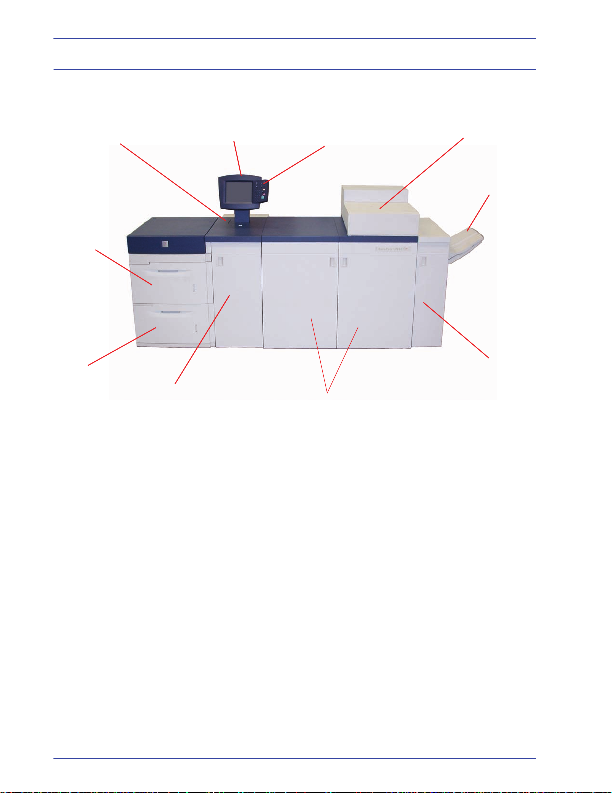
Identifying the external components
Use the illustration below to identify external components listed in
the table on the next page.
Power on/off switch
Tray 1
Tray 2
Transport Module
User Interface
Control Panel
Front Doors
Dry Ink/Toner compartmen
Offset Catch T ray
Exit Module
1-2
DocuColor 8000/7000 Operator Manual
Page 29
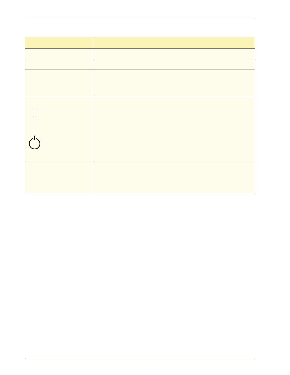
1. Overview
Part Description
Paper Tray 1
Paper Tray 2
Transport Module The Transport Module carries the paper from the paper trays to the upper
On/Off
On
Off
User Inte rface The User Interface contains two components: the Control Panel and the
Holds 2000 sheets of 24 lb. (90 g/m2) paper.
Holds 2000 sheets of 24 lb. (90 g/m2) paper.
paper path of the digital press. It also routes the paper from the lower paper
path of the digital press to the upper paper path of the digital press when
duplexing.
Press the Power Switch to the On position to power on the digital press.
A screen message advises of a short wait while the Fuser warms up and
the digital press runs a system check.
Press the Power Switch to the Off position to power off the digital press.
Allow the digital press to remain off for a minimum of twenty seconds
before switching the power on again.
Touch Screen.
The Touch Screen allows selections to be made by simply touching a
button on the screen.
DocuColor 8000/7000 Operator Manual
1-3
Page 30
1. Overview
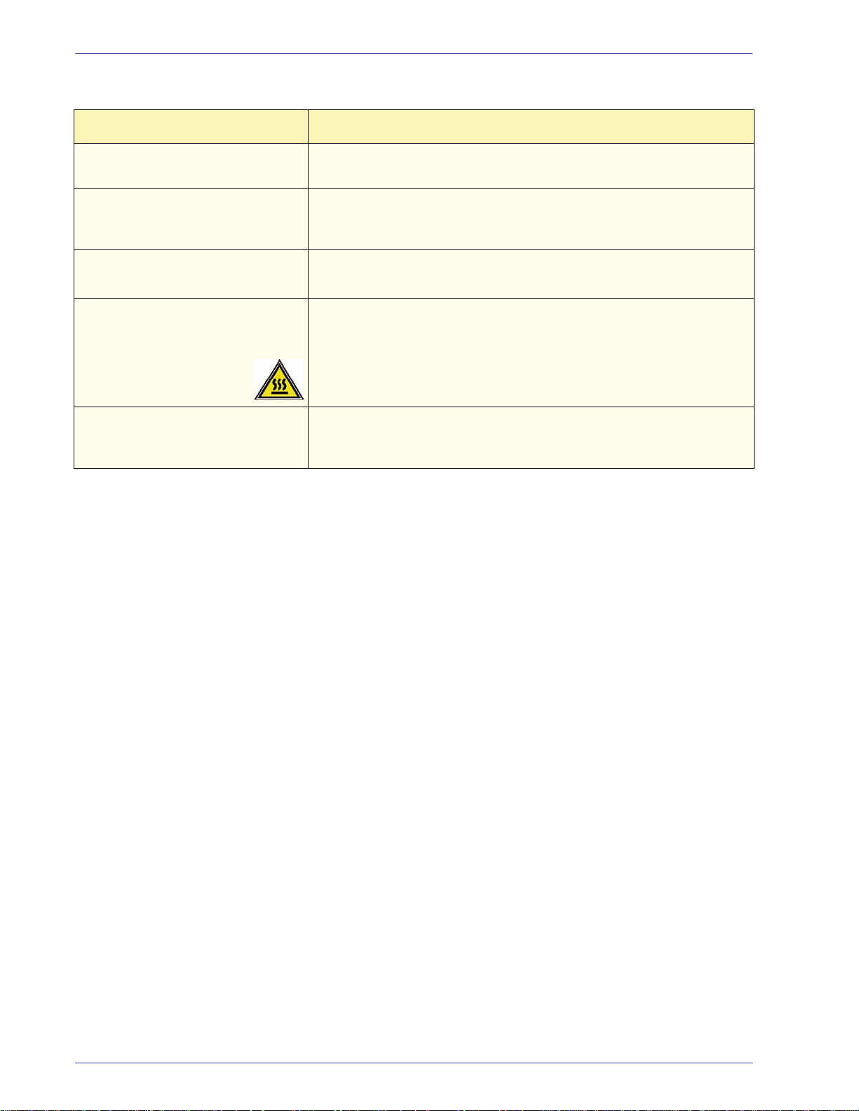
Part Description
Control Panel Allows keypad selection of features. Refer to the Control Panel
section in this chapter.
Dry Ink/Toner Compartment Contains the Dry Ink/Toner cartridges. The cartridge colors from left to
right, are black, cyan, magenta, and yellow. Refer to the Maintenance
Chapter of this manual for instructions on changing the cartridges.
Offset Catch T ray (OCT) Receives completed print job. Sets are offset for easy separation.
2
Maximum capacity is 500 sheets of 24 lb. (90 g/m
) paper.
Right/Left Front Doors Houses the image transfer system for simplex and duplex printing.
Open to clear jams in the paper path in the Printing Module and at the
Fuser. Follow the instructions precisely for clearing a jam in the Fuser.
WARNING: The Fuser is extremely hot and will cause injury if
jam clearing instructions are not followed.
Exit Module Contains the decurler and the inverter. The decurler removes any curl
from the printed page. The inverter is used when duplexing or face
down output is selected.
1-4
DocuColor 8000/7000 Operator Manual
Page 31

Ecology Module
1. Overview
The Ecology Module connected to the back of the DocuColor
8000/7000 contains the environmental components (ozone and
dust filters). The Ecology Module is maintained by the Xerox
service representative.
DocuColor 8000/7000 Operator Manual
1-5
Page 32

1. Overview
Electrical Module
The Electrical Module houses software, printed wiring boards, and
power supplies. The Xerox service representative connects a
laptop to the twenty-five pin connector on the Electrical Module to
load software or run diagnostics. This connector is for the Xerox
service representative only; do not connect a computer cable to it.
CAUTION: Do not block the vents of the Electrical Module.
WARNING: Do not remove the covers or guards that are fastened
with screws. There are no parts behind these covers that you can
maintain or service.
1-6
DocuColor 8000/7000 Operator Manual
Page 33

Dry Ink/Toner Waste Bottle
The Dry Ink/Toner Waste Bottle collects the waste dry ink/toner in
the printing process. The Dry Ink/Toner Waste Bottle is customer
replaceable and located in the rear of the Exit Module.
Refer to the Maintenance Chapter of this manual for instructions
on changing the Dry Ink/Toner Waste Bottle.
Dry Ink/Toner
Waste Bottle
1. Overview
DocuColor 8000/7000 Operator Manual
1-7
Page 34

1. Overview
Ground Fault Indicator (GFI) circuit breakers
The digital press is equipped with two safety circuit breakers
called a Ground Fault Indicators (GFI). These devices trip if the
power to the digital press is interrupted.
Ecology Module
Fuser GFI
Digital Press and
SFM GFI
Fuser GFI The Fuser receives power through the Fuser GFI.
Digital Press GFI The digital press receives power through the Digital Press GFI. If
an optional Second Feeder Module is connected to the Digital
Press, then it too receives power from this GFI.
After a power outage
occurs:
Power on the digital press as soon as possible after the power is
restored, and print a job to ensure that there is no damage to the
digital press.
1-8
DocuColor 8000/7000 Operator Manual
Page 35

1. Overview
If power to the digital press is interrupted,
• Locate the circuit breakers on the Ecology Module on the back
of the digital press next to the toner waste bottle.
• If either device is tripped, the switch is in the Off position
(down). Flip the switch up.
NOTE: I f the device trips again or if power is not restored by the
above procedure, call your Xerox service representative.
CAUTION: The Pressure Pad in the Fuser remains in an up
position if power to the digital press is interrupted while the digital
press is in use. The Pressure Pad is not released from this
position until the power is restored, the Power Switch is in the On
position, and the Start button is pressed.
KEY POINT: If the Pressure Pad remains in the up position for a
prolonged period of time, print quality defects will occur.
DocuColor 8000/7000 Operator Manual
1-9
Page 36

1. Overview
User Interface (UI)
The User Interface (UI) displays messages that indicate the status
of the digital press during idle, run, or fault conditions. The UI also
displays the default screen selected in the Tools Mode by your
System Administrator.
The default screen can be either the Job Status or the Machine
Status screen.
1-10
DocuColor 8000/7000 Operator Manual
Page 37

1. Overview
Message Area
Tabs
Message Area The message area at the top of the UI displays messages
concerning the digital press status, programming conflicts, or
errors. Messages may also provide instructions for the operator.
Tabs and Functions Some UI screens display tabs which contain various selectable
options. Options are initially set to the factory default settings.
These settings can be changed by your System Administrator in
Tools Mode.
Ask your System Administrator for more informa tion regarding
these selections,
or refer to the System Administration Guide.
DocuColor 8000/7000 Operator Manual
1-11
Page 38

1. Overview
Control Panel
Your digital press has one of two Control Panels: a Control Panel
with words or one with international symbols. The function of each
button is described in the table on the following pages.
Name Function
Power Saver Lights up when the digital press is in Sleep
Mode, which lowers the Fuser temperature.
Press to return to Standby Mode.
Job Status Displays a list on the UI of the current jobs and
their status. You can hold, release, promote,
delete, and see the options selected for each job.
Language Allows you to select one of two languages to be
displayed on the UI.
Access Allows access to the password-protected Tools
Mode and the Auditron Mode.
Machine
Status
Accesses the Paper Tray, Machine Details, Error
Log, and Maintenance screens. Machine Status
is where you find the serial number for the digital
press, along with the customer support phone
numbers, and the meters that show the count for
color, black and white, color large size, and total
output.
1-12
DocuColor 8000/7000 Operator Manual
Page 39

1. Overview
Name Function
Help Displays additional information useful in
completing a task.
Clear All The Clear All button is used in the Tools
Mode for clearing certain selections or
settings. It is also used by the service
representative in the diagnostics mode.
Pause Press the Pause button to pause the
printing process in order to perform certain
maintenance procedures such as changing
the fuser oil or the dry ink/toner cartridge.
You must press Pause again to resume the
printing process.
Start The Start button is used in the Tools Mode
for certain settings. It is also used by the
service representative in the diagnostics
mode.
Keypad Use the keypad to enter your password for
access to Tools Mode. Use the keypad for
certain Tools Mode features. The keypad is
also used by the service representative in
the diagnostics mode.
DocuColor 8000/7000 Operator Manual
1-13
Page 40

1. Overview
Job Status
When you press the Job Status button, the Job Status screen is
displayed.
The Job St atus screen can be set as the initial screen default by
your System Administrator. Information about the job includes Job
Type, Current Status, Paper Size, Output Quantity (refers to the
output in sheets for a single page job and in sets or stacks for a
multiple page job), and total Number of Pages.
Jobs are numbered in the order they are received for processing.
Job order in the queue may be modified by an automatic Hold
(something has to be done to the digital press before continuing),
a Manual Hold (at user request), Promotion of one or more jobs,
or Delete a job.
1-14
DocuColor 8000/7000 Operator Manual
Page 41

1. Overview
To perform one of the following functions, you must first touch the
desired job to select it, then touch one of the buttons below.
•Touch Hold Job for a manual hold. When a job is in Hold Job
status in the queue, it does not print when it reaches the top of
the job queue. It is skipped until it is released or deleted.
•Touch Release Job to reactivate a job that is on hold in the
queue. If the job is being held due to a resource (paper, dry
ink/toner, etc.) problem, the job is not released until the
resource is provided. A job that is held due to user request can
be released by touching the Release button.
•Touch Promote Job to advance a selected job in the queue to
be processed after the job that is currently printing. Jobs are
processed on a first-in/first-out basis when multiple jobs are
promoted. Once a job has been promoted, it cannot be
skipped by jobs promoted after it.
•Touch Delete Job to delete a selected job from the queue. You
must answer “Yes” when confirmation of the delete is
requested.
•Touch Job Details for detailed information about a selected
job such as Number of Images processed, Color Mode, Paper
Tray in use, Paper Type, and Finishing.
DocuColor 8000/7000 Operator Manual
1-15
Page 42

1. Overview
Job names are truncated to sixteen characters on the Job Status
screen, which may be fewer characters than are displayed on your
color server screen.
Indicates total number
of pages for the Job List
The Up and Down arrow buttons are
selectable when the total number of jobs
exceeds one page
Name Function
Job List Shows all jobs submitted to the digital press.
Hold Job Holds a job in the print queue until released.
Release Job Releases a Hold Job to be printed.
Promote Job Enables a job to be moved in front of other jobs in
the queue.
Delete Job Deletes a selected job.
Job Details Shows the programmed options for a selected job.
Up/Down Arrows Enables scrolling through job list.
1-16
DocuColor 8000/7000 Operator Manual
Page 43

Power Save r
Language
1. Overview
Pressing the Power Saver button puts the digital press in a
reduced power consumption mode during which the Fuser
temperature is lowered. The digital press automatically goes into
this mode after no activity occurs for the factory default time of
fifteen minutes. This time can be changed in Tools to reflect a
value of 1-240 minutes
.
Refer to the System Administration Guide for further information.
The Language button toggles the UI text between two preset
languages.
DocuColor 8000/7000 Operator Manual
1-17
Page 44

1. Overview
Access
Machine Status
The Access button brings up a screen that requires a password to
enter the Tools or Auditron screens.
Refer to the System Administration Guide for further information
on Tools and Auditron features.
When the Machine Status button on the Control Panel is pressed,
the Paper Trays tab screen is displayed by default. The Machine
Status screen can be set as the initial screen default by your
System Administrator.
1-18
DocuColor 8000/7000 Operator Manual
Page 45

1. Overview
If an optional Second Feeder Module is connected to the digital
press, Trays 3 and 4 will appear in the Paper Supply column.
Screen Name Function
Paper Trays Shows the trays available, and the size, type,
weight and level of the paper in the trays.
Machine Details Displays the customer support phone number,
the serial number of the machine, and access to
the Meters screen.
Error Log Shows all error codes to assist your Xerox
service representative in solving problems with
the digital press.
Maintenance Touch the Customer Replaceable Unit button to
display the status of the Dry Ink/Toner
Cartridges, Dry Ink/Toner Waste Bottle, Charge
Corotrons and Fuser Web. A green check mark
indicates that the status is Okay. A yellow check
mark indicates a Warning. A red circle indicates
a Fault.
DocuColor 8000/7000 Operator Manual
1-19
Page 46

1. Overview
Machine Details t a b
This screen provides the telephone number to call for support, the
machine serial number and access to the meter counts.
Meters keep track of print counts. To view the print count, touch
the Meters button on the Machine Details screen. The Billing
Meters screen is displayed.
1-20
DocuColor 8000/7000 Operator Manual
Page 47

Maintenance tab
1. Overview
To reset the meters to zero, touch the Resettable Meters button.
On the following screen touch the Reset button.
Touch the Customer Replaceable Unit button on the Maintenance
screen to display a list of replaceable items and their status.
DocuColor 8000/7000 Operator Manual
1-21
Page 48

1. Overview
The Customer Replaceable Unit screen displays a gauge or a
check mark indicating the level at which the consumable is.
For example, the gauges for the dry ink/toner cartridges indicate
the amount of toner in each cartridge:
• The cartridge is full when all four bars are red.
3
• The cartridge is
• The cartridge is
• The cartridge
/4 full when three bars are red.
1
/2 full when two bars are red.
1
/4 full when one bar is red.
For the other consumables, such as the Waste Dry Ink Bottle,
each Corotron, and the Fuser Web, the following applies:
• A green check mark indicates that the level of the consumable
is adequate
• A yellow triangle alerts you that the level is low, and
• A red circle indicates that the consumable is depleted
When a consumable item is depleted, the digital press
automatically interrupts the current job and does not restart until
the consumable is replaced.
1-22
DocuColor 8000/7000 Operator Manual
Page 49

1. Overview
Your Xerox service representative uses the Service Engineer
Replaceable Unit function to check on the status items that are
replaced only by the service engineer.
These items include the fuser oil and the second bias transfer belt.
DocuColor 8000/7000 Operator Manual
1-23
Page 50

1. Overview
Help
Audio tones
Press Help for an overview of the different options displayed in the
various tabs on the UI.
There are three audio tones:
• Attention:
The Attention Tone sounds six seconds after a scan job has
been completed to remind you to remove the document from
the Scanner glass.
• Button Selection:
A single tone indicates that the button you pressed can be
selected. A double tone indicates that the button is not
available.
• Fault:
The Fault Tone indicates that the digital press is in a fault
condition and does not operate until the fault is cleared.
The Audio Tones can be deactivated or made louder or softer
through the Tools Mode.
For more information, refer to the System Administration Guide.
1-24
DocuColor 8000/7000 Operator Manual
Page 51

Alert screens
1. Overview
An Alert screen has a red bar across the screen when a
consumable product, such as Dry Ink/Toner, needs to be replaced.
An Alert screen also indicates that the digital press is unable to
make prints because of a fault condition. Follow the instructions
on the UI to resolve the problem and resume printing.
DocuColor 8000/7000 Operator Manual
1-25
Page 52

1. Overview
Identifying the internal components
Charge Corotron Assemblies
Paper Transport Drawer
Serial number label
If the digital press loses power and it is impossible to access the
Machine Details tab for the serial number, open the two main front
doors. The serial number label is in the center of the bottom frame
of the digital press.
Paper T ransport drawer
This area is where paper is aligned, the image is applied and
fused, and the paper is flipped over if duplexing is required.
Serial Number Label
1-26
DocuColor 8000/7000 Operator Manual
Page 53

Transport Module
1. Overview
Paper from all trays moves through the Transport Module to the
upper paper path in the digital press. The lower paper path
carries duplexed sheets through the Transport Module to the
digital press upper paper path.
Tray 1
Upper paper path
Tray 2
Lower paper path
DocuColor 8000/7000 Operator Manual
1-27
Page 54

1. Overview
rt
Paper path in the digital press
The paper path transfers an image to the paper and fuses it for
both the simplex and duplex selections. It has two areas, the
upper paper path and the lower paper path. The upper path is
used for both simplexing and duplexing. The lower path is used
for duplexing only. The Horizontal Transport 1 decurls the paper
when printing duplex.
Inverter
Gate
From Transport Module
To Transport Module
Alignment
Transport
Horizontal Transport 2
Vacuum
Transport
Inverter Transport
Fuser Transport
Horizontal Transport 1
To the Exit Module
From the Duplex
Inverter Transpo
1-28
DocuColor 8000/7000 Operator Manual
Page 55

Exit Module
1. Overview
A completed print passes through the Exit Module to the Offset
Catch Tray or other finishing device. The Exit Module contains a
Decurler that removes paper curl caused by the fusing
process. The Exit Module also contains an Inverter which turns
the paper over to image side two when duplexing, or when face
down output is selected.
To the
output
device
Decurler
From Digital Press
T o Inverter Transport
To Digital Press
Duplex Inverter
Transport
DocuColor 8000/7000 Operator Manual
1-29
Page 56

1. Overview
Relocating the digital press
If you need to relocate the digital press, call your Xerox customer
representative. The Installation Planning procedure must be
conducted for every new site.
Customer documentation updates
You can get the latest customer documentation updates for your
digital press by going to www.xerox.com
check this website for the latest information for your digital press.
. Be sure to periodically
1-30
DocuColor 8000/7000 Operator Manual
Page 57

2. Paper and paper trays
Recommended Materials List (RML)
Refer to the Color Materials Usage Guide, the Recommended
Materials List, and the Speciality Media Guide: Hints and Tips for
paper guidelines. The Recommended Materials List and the
Speciality Media Guide: Hi nts and T ips documents are updated on
an on-going basis to include new papers and other media. PDF
files are available at www.xerox.com
DocuColor 8000/7000 and follow the path until you reach the files
to download.
Paper handling
. Use the search parameter
x
o
r
e
X
Label on ream
instructs you to
“Print arrow side
first”
For the best performance, load paper with the seam side up in all
the paper trays. The seam side is where the ream of paper is
sealed. Refer to the label on the paper ream.
NOTE: Many suppl iers use arrows on the product labels to
indicate the preferred side to image first. Use this side (as
signaled by the arrow) as equivalent to the seam side when
loading the paper.
DocuColor 8000/7000 Operator Manual
2-1
Page 58

2. Paper and paper trays
Stored paper: • On a flat surface. Do not store paper directly on the floor, since
Many factors affect the performance of paper, including room
temperature, humidity, paper quality, dust, and the size of the
image area. If jams or paper curl problems occur, remove the
paper from the paper tray, turn it over, place it back in the paper
tray, and resume printing. If the problem is rectified, continue to
load your paper in the same manner.
If the problem is not rectified, load a new ream of paper and try the
process again. If the problem persists, your System Administrator
may go into the Tools Mode and try the different decurler
settings. If, after trying all the previous suggestions, the problem
still persists, call your Xerox representative.
For reliable digital press operation and good print quality, Xerox
recommends the following:
this increases the possibility of moisture absorption. Paper
should be stored on pallets, shelves, or in cabinets in an area
protected from extremes of temperature and humidity.
• In a low dust area.
• In a low humidity area. Humidity is one of the most important
steps to promote proper paper characteristics. Optimum paper
storage conditions include a relative humidity of 35-55%. An
increase in humidity may cause paper to develop wavy edges.
This occurs because the edges absorb moisture while the rest
of the ream remains unaffected. Wavy edges causes jams and
misfeeds.
• In an air-tight, moisture-proof container.
2-2
DocuColor 8000/7000 Operator Manual
Page 59

2. Paper and paper trays
• In a controlled temperature. The temperature in the room
where paper is stored has a significant effect on how that
paper performs in the machine. Optimum paper storage
temperature is 68-76
° F (20-24.4° C).
For additional paper handling information, refer to the Color
Materials Usage Guide.
Cutting and trimming paper Proper cutting of the paper is important. Mills that offer paper in
“cut sizes” crop their papers using state-of-the-art rotary slitters on
high performance systems. Slitting and edge trimming by circular
knives with dust removal at every cutting point prevents
contamination of the paper.
Trimming papers from parent sheets to get the desired output size
may generate dust if dull knives are used. The recommendation is
to delay trimming until printing has been finalized to prevent paper
dust generation and contamination.
If pre-printing is imperative, an in-house maintenance program,
including knife sharpness maintenance and dust removal with a
vacuum or air system, are key to achieving good results.
DocuColor 8000/7000 Operator Manual
2-3
Page 60

2. Paper and paper trays
Paper trays
Paper Trays 1 and 2 are the standard paper trays for the basic
configuration of the digital press. The following figure shows the
paper path from trays 1 and 2 through the Transport Module.
Transport
Module
Tray 1
To the digital
press
Tray 2
From the
Horizontal
(Duplex)
Transport
2-4
DocuColor 8000/7000 Operator Manual
Page 61

Paper guidelines
SEF
LEF
2. Paper and paper trays
For the best results, remember the following:
• Do not load paper or other materials above the MAX line on
the rear paper guide.
• Do not store extra reams of paper in the paper trays.
• Do not use wrinkled, torn, curled, or folded paper.
• Use the paper sizes and weights shown in the Recommended
Materials List.
• Follow the suggestions in the Specialty Media Guide: Hints
and Tips.
• Do not mix sizes or weights of paper in a paper tray.
• Ensure that the tray indicator LEDs are set for the correct
paper size, weight range, and paper type.
Copy paper is fed into the digital press in one of two positions:
long edge feed (LEF) or short edge feed (SEF). Long edge refers
to the long edge of the paper. When you see LEF, position the
paper so the long edge is fed first. Short edge refers to the short
edge of the paper. When you see SEF, position the paper so the
short edge is fed first.
NOTE: It is imperative that you load paper with the paper guides
adjusted properly. If the paper is NOT loaded properly, it skews
and jams occur.
DocuColor 8000/7000 Operator Manual
2-5
Page 62

2. Paper and paper trays
Curl
When paper is exposed to heat, the paper loses moisture and
curls toward the heat source. High coverage jobs tend to curl more
due to the toner plastification effect on the paper surface. The
system tries to reduce this by using mechanical devices within the
paper path called decurlers.
Your system has been designed with an automatic curl control
system that uses information such as: the amount of coverage on
the page, paper weight, whether the paper is coated or uncoated,
and the current humidity and temperature to determine the
amount of pressure needed at the different decurlers to reduce
output curl.
If you are experiencing excessive curl, remove the paper from the
tray, turn it over and replace it in the tray. If the curl is still
excessive, refer to the System Administration Guide, Tools Mode
chapter, to change the decurler settings to accommodate the
environmental and pape r conditions.
2-6
DocuColor 8000/7000 Operator Manual
Page 63

2. Paper and paper trays
Paper specifications
Paper All Paper Trays
Minimum Paper Size 182mm x 182mm
(7.16 x 7.16”)
Maximum Paper Size 320mm x 488mm
(12.6 x 19.2”)
Standard Sizes B5 LEF/SEF A4 LEF/SEF
B4 SEF A3 SEF
8 x 10” LEF 8.5 x 11” LEF/SEF
8.5 x 13” SEF 8.5 x 14” SEF
11 x 17” SEF 12 x 18” SEF
Kai8 SEF Kai16 LEF
12.6 x 17.7” SEF
X
12.6 x 19.2” SEF
X
Paper Weight Range
Transparencies
H
60 - 300 g/m
Yes
2
(A4 LEF or 8.5 x 11” LEF)
LabelsH Yes
Transfer Paper
Coated Paper
Tabbed Inserts
H
u b
D
No
Yes
Yes
Drilled Yes: 2, 3, 4 hole
X
Refer to the Non-Standard Size Paper section in this chapter.
D
Refer to the Tabbed Inserts section in this chapter.
H
Refer to the Recommended Materials List and the Speciality
Media Guide for guidelines.
u
Duplex is limited to paper that is 220 g/m2 or less.
b
L80 g/m2 cannot duplex in high humidity. L85 g/m2 coated media
is not allowed.
DocuColor 8000/7000 Operator Manual
2-7
Page 64

2. Paper and paper trays
Tray capacity
Duplexing
Transparency guidelines
All paper trays have a capacity of 2000 sheets of 24 lb. (90 g/m2)
paper.
The DocuColor 8000/7000 duplexes prints from all paper trays up
to 220 g/m
2
. The system does not duplex media larger than 12.6 x
18 inch (321.1 x 458.1 mm).
Transparencies can be run from all the paper trays.
Use only the transparencies recommended:
• Xerox Removable Paper Stripe: USA and Canada, 3R5765;
Xerox Europe, 3R93179.
• Load transparencies into a tray with the paper stripe side
facing DOWN and with the stripe as the leading edge. (The
leading edge is the edge that feeds into the digital press first.)
• Do not mix paper and transparencies in a tray. Jams may
occur.
• Ensure that Transparency is selected in the Paper Weight
section at the top/front of the paper tray.
2-8
DocuColor 8000/7000 Operator Manual
Page 65

Tabbed inserts
2. Paper and paper trays
Tabbed Inserts can be loaded into the paper trays as NonStandard paper.
• When loading, the non-tabbed, short edge of the tabbed insert
should be the lead edge to the digital press.
• If a jam occurs while running tabbed sets, there is no recovery
procedure.
• You have to manually reassemble your originals and
prints, determine where the job left off, and resume printing
or cancel the job and start again.
• The size of the tabbed insert should be 9 x 11 inch (229 x 279
mm) for letter size tabs (223.5 x 296 mm for A4 equivalent
tabs).
• The correct weight of the insert should be selected on the
tray.
• Select Non-Standard size on the paper tray and on the UI,
Tools Mode, input 11 inches or 296 mm for A4 as the X axis
and 9 inches or 223.5 mm for A4 as the Y axis dimensions for
SEF.
Refer to the System Administration Guide for the procedure to
program non-standard size paper.
DocuColor 8000/7000 Operator Manual
2-9
Page 66

2. Paper and paper trays
Drilled paper
Three-hole drilled paper can be run from all the trays either LEF or
SEF with the holes facing any direction.
NOTE: If you are stapling 3-hole drilled paper with the optional
High Capacity Stacker Stapler 80 (HCSS80), refer to the
Accessories chapter for paper loading instructions, based on the
position of the staple.
Drilled paper should be run in the Simplex (1-sided) and Duplex
(2-sided) orientations shown below to avoid paper jams caused by
the holes not aligning correctly with the paper sensor in the press.
Simplex Print Jobs
Load the drilled paper into any tray in the Long Edge Feed (LEF)
direction. Refer to the following illustration:
Rear of paper tray
Duplex Print Jobs
Load drilled paper into any tray in either the Long Edge Feed
(LEF) or Short Edge Feed (SEF) direction. Refer to the following
illustration:
LEF direction
Rear of paper tray
Paper
tray
guides
Front of paper tray
Paper
tray
guides
Front of paper tray
Right
side
Right
side
SEF direction
Rear of paper tray
Paper
tray
guides
Front of paper tray
2-10
NOTE: If you are stapling 3-hole drilled paper with the optional
High Capacity Stacker Stapler 80 (HCSS80), refer to the
Accessories chapter
(see page 3-27 and page 3-43) for paper
loading instructions, based on the positi on of the staple.
DocuColor 8000/7000 Operator Manual
Page 67

Letterhead
Different inks and dry inks/toners are used to produce preprinted
letterhead that may not pass through the digital press intact.
Refer to the Specialty Medi a Guide: Hint s a nd T ip s fo r inf ormati on
on using preprinted letterhead p aper.
Nonstandard size paper
Nonstandard size paper is identified as any paper for which there
is no paper guide setting within the minimum and maximum sizes
for the trays: 7.16 to 12.6 inch LEF or 7.16 to 19.2 inch SEF (182 320 mm LEF or 182 x 488 mm SEF)
Non-Standard size paper can be loaded into all the trays. The
Non-Standard setting must be selected on the top/front of the
paper tray.
2. Paper and paper trays
Refer to the System Administration Guide for the procedure to
program a Non-Standard size paper to be the default setting for a
particular tray .
DocuColor 8000/7000 Operator Manual
2-11
Page 68

2. Paper and paper trays
Auto Tray Switching
Auto Paper Selection
When Auto Tray Switching (ATS) is activated in the Tools Mode,
the digital press automatically switches to another tray containing
paper of the identical size, weight, type, and feeding orientation
(SEF or LEF) when the tray being used is empty.
Refer to the System Administration Guide for the instruction on
enabling ATS.
Auto Paper Selection (APS) can be enabled in the Tools
Mode. When enabled, the digital press automatically selects the
paper tray containing the correct size paper without a specific
paper tray being selected.
Refer to the System Administration Guide for information on how
to enable Auto Paper Selection or t o sel ect a particular tray as the
default setting.
When the Single Paper Weight setting in Tools Mode is selected
as the default setting, Auto Paper selects only 81-105 g/m
2
paper
in the correct size. When the Mixed Paper Weight Productivity
Setting is enabled, Auto Paper selects only 106-135 g/m
2
paper in
the correct size.
2-12
DocuColor 8000/7000 Operator Manual
Page 69

Loading paper
2. Paper and paper trays
Use this procedure to load paper in any paper tray.
1. Pull out the tray slowly until it stops.
2. Load the correct size paper into the tray in the correct feeding
orientation. Refer to the orientation labels on each tray.
• Load the paper seam side (the side on which the ream of
paper is sealed) up in all the trays.
• Do not load materials above the MAX line located on the
rear Edge Guide.
• Do not store extra reams of paper in the open area of the
paper trays. The tray will become inoperable until the
paper is removed.
NOTE:Many suppliers use arrows on the paper ream
labels to indicate the prefe rred side t o image first . Use th is
side (as indicated by the arrow) as equivalent to the seam
side when loading the paper.
3. Adjust the paper guides by pressing in the guide release and
carefully moving the Edge Guide until it lightly touches the
edge of the material in the tray.
4. Although all the trays have auto size detection capability, the
paper weight (g/m
2
) range must be selected on the Weight
Indicator at the top/front of each tray.
• Selecting the correct paper weight range affects the
throughput performance and image quality.
DocuColor 8000/7000 Operator Manual
2-13
Page 70

2. Paper and paper trays
• Press the selection button until the light next to the
correct weight is illuminated.
• Refer to the Paper Weight Conversion Tables in this
chapter to convert pounds to grams.
5. Select Transparency if you are running transparencies.
6. Select Non-Standard paper if the size indicators for the paper
guides inside the tray do not show the size of the paper you
are loading.
7. Select Coated or Uncoated paper.
Selection buttons
Wordless label
Selection buttons
2-14
DocuColor 8000/7000 Operator Manual
Page 71

2. Paper and paper trays
Paper trays air adjustment: Blowers help control the environmental conditions in the paper
trays to ensure optimum print capability:
• Each paper tray has two blowers and two fans. The
blowers are located in the front of each tray, while the two
fans are located on the right-side of the tray.
• The lead edge blower is on at all times and produces
heated air if one of the following selections are made:
Coated paper, Transparencies, or plain paper 106 g/m
heavier. The trail edge blower is on at all times and does
not produce heated air.
• The paper trays also have air adjustment levers on the
drawer to regulate the direction of the air.
8. If the paper weight is between 64 and 256 g/m
2
, the position
of the air adjustment levers should be toward the front of the
tray.
9. If the paper weight is between 257 and 300 g/m
2
, the position
of the air adjustment levers should be positioned toward the
rear of the tray.
2
or
DocuColor 8000/7000 Operator Manual
2-15
Page 72

2. Paper and paper trays
Paper weight conversion tables
Specific weight conversion
Xerographic
Grammage
60 16 41 22 33 27
64 17 43 24 35 29
75 20 50 28 41 34
80 21 54 30 44 36
90 24 60 33 50 41
105 28 70 39 58 48
120 32 80 44 66 55
135 35 90 50 75 62
150 40 100 55 83 67
158 42 107 58 87 72
163 43 110 60 90 74
176 47 119 65 97 80
g/m
2
Bond, Writing,
pounds
17 x 22” - 500
sheets
Offset, Text,
Book,
pounds
25 x 38”-
500 sheets
Cover,
pounds
20 x 26” -
500 sheets
Index,
pounds
25.5 x 30.5”
- 500 sheets
Bristol and
Tag, pounds
22.5 x 28.5”
- 500 sheets
200 53 135 74 110 91
203 54 137 75 112 93
216 57 146 80 119 98
220 59 149 81 122 100
259 66 169 92 140 114
280 74 189 104 155 128
300 74 189 104 155 128
Yellow shading indicates grades widely used for this classification
2-16
DocuColor 8000/7000 Operator Manual
Page 73

Weight conversion ranges
2. Paper and paper trays
Xerographic
Bond,
Grammage
60 - 80 17 - 21 43 - 54 24 - 30 35 - 44 29 - 36
81 - 105 22 - 28 55 - 70 31 - 39 45 - 58 37 - 48
106 - 135 29 - 36 71 - 90 40 - 44 59 - 75 49 - 62
136 - 150 37 - 40 91 - 100 45 - 55 76 - 83 63 - 67
151 - 220 41 - 59 101 - 149 56 - 81 84 - 122 68 - 100
221 - 300 60 - 74 150 - 189 82 - 110 123 - 166 101 - 128
g/m
2
Writing,
pounds
17 x 22” -
500 sheets
Offset, Text,
Book,
pounds
25 x 38” -
500 sheets
Cover,
pounds
20 x 26: -
500 sheets
Index,
pounds
25.5 x 30.5”
- 500 sheets
Bristol and
Tag, pounds
22.5 x 28.5”
- 500 sheets
DocuColor 8000/7000 Operator Manual
2-17
Page 74

2. Paper and paper trays
2-18
DocuColor 8000/7000 Operator Manual
Page 75

3. Accessories
NOTE: The optional High Capacity Feeder for the DocuColor
2060/2045 may be used with the DocuColor 8000/7000. When
connected, it will appear as “Tray 3” on the feature selection
screens.
Trays 3 and 4 (Second Feeder Module)
The Second Feeder Module is an optional feeding device that
contains Trays 3 and 4. This module holds the same number and
types of substrates as the First Feeder Module (FFM), which
contains Trays 1 and 2. The First Feeder Module is not optional
and is permanently connected to the digital press.
Each tray holds a maximum of 2000 sheets of 24 pound (90 g/m
paper. Chapter 2 provides more information on using specific
types of paper.
2
)
NOTE: Always refer to the Recommended Materials List and the
Speciality Media Guide.
DocuColor 8000/7000 Operator Manual
3-1
Page 76

3. Accessories
Identifying the parts
Second Feeder Module
Tray 3
Tray 4
Tray 1
Tray 2
First Feeder Module
3-2
DocuColor 8000/7000 Operator Manual
Page 77

Paper path
e
3. Accessories
Paper feeds from the right side of the trays. Sheets move from the
transport area behind the right door of the SFM to the Upper
Transport area above Paper Trays 1 and 2, then through the
Transport Module and into the press.
SFM Transport Area
Tray 3
Tray 4
Upper Transport Area
Tray 1
Tray 2
Tr ansport Modul
DocuColor 8000/7000 Operator Manual
3-3
Page 78

3. Accessories
Paper guidelines
For the best results, remember the following:
• Do not load paper or other materials above the MAX line on
the rear paper guide.
• Do not store extra reams of paper in the paper trays.
• Do not use wrinkled, torn, curled, or folded paper.
• Use the paper sizes and weights shown in the Recommended
Materials List.
• Follow the suggestions in the Specialty Media Guide: Hints
and Tips.
• Do not mix sizes or weights of paper in a paper tray.
• Ensure that the tray indicator LEDs are set for the correct
paper size, weight range, and paper type.
NOTE: It is imperative that you load paper with the paper guides
adjusted properly. If the paper is NOT loaded properly, it will skew
and jams will occur.
3-4
DocuColor 8000/7000 Operator Manual
Page 79

Paper Specificat ions
Paper All Paper Trays
Minimum Paper Size 182mm x 182mm
(7.16 x 7.16”)
Maximum Paper Size 320mm x 488mm
(12.6 x 19.2”)
Standard Sizes B5 LEF/SEF A4 LEF/SEF
B4 SEF A3 SEF
8 x 10” LEF 8.5 x 11” LEF/SEF
8.5 x 13” SEF 8.5 x 14” SEF
11 x 17” SEF 12 x 18” SEF
Kai8 SEF Kai16 LEF
12.6 x 17.7” SEF
1
12.6 x 19.2” SEF
3. Accessories
1
Paper Weight Range
Transparencies
2
60 - 300 g/m
Yes
2
(A4 LEF or 8.5 x 11” LEF)
2
Labels
Transfer Paper
Coated Paper
Tabbed Inserts
2
3 4
5
Yes
No
Yes
Yes
Drilled Yes: 2, 3, 4 hole
1
Refer to the Non-Standard Size Paper section in this chapter.
2
Refer to the Recommended Materials List and the Speciality
Media Guide for guidelines.
3
Duplex is limited to paper that is 220 g/m2 or less.
4
L80 g/m2 cannot duplex in high humidity. L85 g/m2 coated media
is not allowed.
5
Refer to the Tabbed Inserts section in this chapter.
DocuColor 8000/7000 Operator Manual
3-5
Page 80

3. Accessories
Loading paper
There are three settings at the top front of the paper trays that
must be selected so the system can make adjustments that affect
the throughput performance and image quality of your prints.
• Paper Size: Non-Standard or Standard
Select Non- St andard Paper if the size indicators for the paper
guides inside the tray do not show the size of the paper you
are loading.
• Paper Weight: Transparency or weight ranges.
Select Transparency or the weight range for the paper being
loaded.
• Paper Type: Coated or Uncoated
Press the selection button until the light next to the correct
selection illuminates.
Wordless label
Selection buttons
Selection buttons
3-6
DocuColor 8000/7000 Operator Manual
Page 81

Paper trays air adjustment
Blowers help control the environmental conditions in the paper
trays to ensure optimum print capability:
• Each paper tray has two blowers. The lead edge blower is
• The paper trays also have air adjustment levers on the
Slide the Air Adjustment Levers to accommodate the weight of the
paper loaded. Slide the lever forward for paper between 64 and
256 g/m
toward the back of the tray.
3. Accessories
on at all times and produces heated air if one of the
following selections are made: Coated paper,
2
Transparencies, or plain paper 106 g/m
or heavier. The
trail edge blower is on at all times and does not produce
heated air.
drawer to regulate the direction of the air. If the paper
weight is between 64 and 256 g/m
2
, the position of the air
adjust levers should be toward the front of the tray. If the
2
paper weight is between 257 and 300 g/m
, the position of
the air adjust levers should be positioned toward the rear
of the tray.
2
. For papers between 257 and 300 g/m2, slide levers
DocuColor 8000/7000 Operator Manual
3-7
Page 82

3. Accessories
Jam clearance
Physical characteristics
A paper jam anywhere in the digital press is indicated by a
message on the UI. Follow the instructions displayed to clear the
jam in the area or areas displayed on the screen and to resume
printing. Jam clearance instructions are also provided in the
Problem Solving chapter.
Size
41.7 inches/1060 mm W x 29.5 inches/750 mm D x 38 inches/969
mm H.
Weight
551 pounds/250 Kg.
Floor space requirements
Ask your Xerox representative to refer to the DocuColor
8000/7000 Installatio n Planni ng Guide for installation work space
requirements.
3-8
DocuColor 8000/7000 Operator Manual
Page 83

High Capacity Stacker 80
3. Accessories
The High Capacity Stacker 80 (HCS80) is an optional finishing
device that provides stacking and offsetting capabilities for output
to a Stacker Tray. The HCS80 connects to the right side of the
digital press and replaces the Offset Catch Tray.
The Stacker Tray has a capacity of 3500 sheets of 24 lb (90 g/m
2
centerline paper (or 370 mm high). The Top Tray has a capacity of
250 sheets of 24 lb 90 gm
2
centerline paper. The HCS80 is
supplied with two Stacker Carts. If needed, you can purchase an
additional Stacker Cart. Contact your Xerox representative for
further details.
NOTE: The Stack Tray cannot support more than 99 lb. (45 kg) of
printed material and therefore, cannot hold 3500 sheets of coated
paper (for example SRA3).
)
DocuColor 8000/7000 Operator Manual
3-9
Page 84

3. Accessories
With the HCS80 you can:
• Select Offset Mode when collated sets are sent to the Stacker
Tray.
• Send documents to the top tray.
• Send sets of different sizes to either the Stacker Tray or the
top tray.
NOTE: Do not stack larger sets on top of smaller sets. Jams
could result.
• Send a sample set to the top tray.
• Chain two stackers to the digital press and send collated sets
to Stacker 1, Stacker 2 or Both Stackers.
• Send collated sets through the stacker to another connected
finishing device.
3-10
DocuColor 8000/7000 Operator Manual
Page 85

Identifying the parts
Control panel
8
9
3. Accessories
7
6
5
1
Name Function
1 Ready light The Ready light blinks during initialization and is constant when the HCS80 is in use
or in standby mode.
2 Sample set
button
3 Unload
button
4 Unload light Illuminates when the Stacker Tray has reached the down position and the front door
Press to have the HCS80 deliver the next collated set to the top tray.
Press once to lower the Stacker Tray and unlock the front door. If pressed while
running a job, all sheets in the paper path are delivered before the Stacker Tray
starts to lower.
can be opened.
2
3
4
DocuColor 8000/7000 Operator Manual
3-11
Page 86

3. Accessories
Name Function
5 Wait light Blinks when the Stacker Tray is moving up or down.
6 Fault code
display
7 Top tray jam
area
8 Bypass jam
area
9 Stacker tray
jam area
Keypad Used by the service representative for diagnostics (not shown). The keypad is
Displays a code when a fault occurs in the HCS80. Refer to the HCS80 fault code
table located in the Problem Solving section of this chapter.
Blinks when there is a jam.
Blinks when there is a jam.
Blinks when there is a jam or the door is open.
located on the front right of the control panel.
3-12
DocuColor 8000/7000 Operator Manual
Page 87

Cooling fan
The HCS80 is equipped with a cooling fan that you can switch on
and off as required. The cooling fan is located inside the front
door:
3. Accessories
HCS80 Cooling Fan
The cooling fan is normally Off. The fan must be switched On
when you are using coated paper than weighs 120 g/m
greater.
For coated paper than weighs less than 120 g/m
uncoated paper, the fan should be switched Off.
2
(80 lb.) or
2
(80 lb.) and for
DocuColor 8000/7000 Operator Manual
3-13
Page 88

3. Accessories
To s wi tch On the cooling fan, perform the following steps:
1. Open the front door of the HCS80.
2. Press the cooling fan power switch to the On position.
HCS80 Power switch
KEY POINT: Only switch on the cooling fan when running paper
that weighs 120 g/m
2
(80 lb.) or greater.
NOTE: Remeber to switch off the fan after your job (s) finsihes and
when running paper that weigh less than 120 g/m
2
(80 lb.).
3-14
DocuColor 8000/7000 Operator Manual
Page 89

Paper path
From the digital press
.
KEY POINT: Labels must be sent to the Top Tray.
Top Tray
Sheets are transported to the Top Tray:
• When sheets are purged after a paper jam.
• When the Sample Set button is selected.
• When selected as an Output Location.
3. Accessories
T op Tray
Bypass
Stacke r Tray
Stacker Tray
Collated sets are transported to the Stacker Tray.
Bypass
The Bypass transports collated sets through the HCS80 to a
connected finishing device or to another HCS80.
If your system configuration has two stackers, the bypass on the
second stacker is not available.
Cart
Stacker Cart
DocuColor 8000/7000 Operator Manual
3-15
Page 90

3. Accessories
Paper guidelines
• Stacker Tray will accept 64-280 g/m2 (either coated or
uncoated stock) with the possibility of degraded stock quality
and increased jam rate
• Transparencies may be run to either the Top Tray or the Stack
Tray. Stack height should be limited to 100 transparencies.
• Coated paper lighter than 100 g/m
coated paper heavier than 100 g/m
• Non-standard papers longer than 305 mm (12") in the feed
direction require 210 mm (8.3") minimum measurement across
the feed direction.
• Non-standard papers shorter than 254 mm (10”) in the cross-
feed direction require 330 mm (13”) minimum measurement in
the feed direction.
Recommended baseline/ce n terline
2
may not run as reliably as
2
.
The following papers are considered to be baseline/centerline and
are recommended to ensure you receive the best quality from
your HCS80:
2
2
.
, 24 lbs. In
2
/80
• Uncoated: Xerox Digital Color Xpressions+, 90 g/m
Europe, Xerox Digital Color Colotech+ 90 g/m
• Coated: Xerox Digital Color Gloss Coated Text (120 g/m
lbs.) In Europe, Xerox Digital Color Colotech + Gloss Coated
120 g/m
2
.
3-16
DocuColor 8000/7000 Operator Manual
Page 91

Paper specifications
Paper Size Output
3. Accessories
Industry
Designation
Inches Orientation Stacker Tray
60 - 300g/m
2
Bypass
60 - 300 g/m
2
60 - 300 g/m
B5 7.2 x 10.1 SEF Yes Yes Yes
B5 7.2 x 10.1 LEF Yes Yes Ye s
A4 8.3 x 11.7 SEF Yes Yes Yes
Letter 8.5 x 11 SEF Yes Ye s Yes
8.5 x 13 SEF Yes Yes Yes
Legal 8.5 x 14 SEF Yes Yes Yes
B4 10.1 x 14.3 SEF Ye s Yes Yes
11 x 14.9 SEF Yes Yes Yes
Tabloid 11 x 17 SEF Yes Yes Yes
A3 11.7 x 16.5 SEF Ye s Yes Yes
12 x 18 SEF Yes Yes Yes
SRA3 12.6 x 17.7 SEF Yes Ye s Yes
8 x 10 LEF Yes Yes Yes
Top Tray
2
A4 8.3 x 11.7 LEF Ye s Yes Yes
Letter 8.5 x 11 LEF Yes Yes Yes
Kai8 10.5 x 15.3 SEF Ye s Yes Yes
Kai16 10.5 x 7.6 LEF Yes Yes Yes
Transparencies A4 & Letter LEF Ye s* Yes* Yes*
Labels A4 & Letter LEF No Yes * Yes *
*Customer recommendation is to run stacks of less than 100, but
there is no system limit on customer selection.
DocuColor 8000/7000 Operator Manual
3-17
Page 92

3. Accessories
Unloading the Stacker Tray
Use the following procedure to unload the Stacker Tray when it is
full, or you want to retrieve a job that has been completed.
1. Press the Unload button on the Stacker Control Panel. The
Wait light blinks until the Stacker Tray has reached the down
position.
2. Open the front door when the Unload Light illuminates.
3. Position the securing bar on top of the stacked paper.
4. Pull the Stacker Cart straight out.
5. Remove the securing bar.
6. Remove the paper from the Stacker Tray.
7. Push the empty Stacker Cart straight into the HCS80.
8. Position the securing bar on the fixed area inside the HCS80.
NOTE: The front door will not close if the securing bar is not
properly attached to the stacker frame.
9. Close the HCS80 front door.
10. Follow the instructions displayed on the digital press UI to
resume printing.
3-18
DocuColor 8000/7000 Operator Manual
Page 93

Selecting Features
How to Enable Automatic Output Switching
3. Accessories
For jobs coming through the network, refer to the documentation
that came with your color server for information on how to select
stacker options on the print driver screens.
If your system configuration contains two stackers, you have the
option to enable Automatic Output Switching. With Automatic
Output Switching, the digital press automatically selects a usable
Stacker Tray to deliver your collated sets.
When the Stacker Tray becomes full or when the Unload button is
selected, the digital press delivers all paper in the digital press to
the same Stacker Tray and then switches to the other Stacker Tray
for the rest of the job.
NOTE: The Stacker Tray has a capacity of 3500 sheets of 24 lb
(90 g/m
2
) centerline paper (or 370mm high). Always refer to the
Recommended Materials List and the Speciality Media Guide for
up-to-date information on using specifi c media types with the
HCS80.
KEY POINT: If Auto Tray Switching feature is not enabled, in
Tools Mode, the button for Both Stackers is not selectable. For
detailed information on how to enable this feature, refer to the
DocuColor 8000/7000 System Administration Guide.
DocuColor 8000/7000 Operator Manual
3-19
Page 94

3. Accessories
Using a DFA Finishing Device
Jam clearance
A DFA (Digital Finishing Architecture) finishing device can be
connected directly to the digital press, or the HCS80.
All DFA devices are installed by your Xerox service
representative. Once installed, the UI screens provide Finishing
Module selections.
For jobs coming through the network, refer to the documentation
that came with your color server for information on how to select
DFA options on the print driver screens.
A paper jam in the HCS80 will be indicated by a message on the
digital press UI. Follow the instructions displayed. The image on
the HCS80 Control Panel will flash showing the area where the
jam is located.
3-20
DocuColor 8000/7000 Operator Manual
Page 95

Clear Bypass area jam
Perform the following steps to clear the HCS80 jam in the Bypass
area and resume printing.
1. Remove any paper from the Top Tray.
3. Accessories
2. Lift the HCS80 Top Cover.
3. Lift the green handle, or handles, indicated on the UI and
remove all paper in the Bypass area. Remove paper only from
the areas indicated.
4. Close each green handle.
5. Close the HCS80 Top Cover.
6. If the UI indicates there is a jam in the digital press, follow the
instructions on the screen to remove any paper in the area
indicates. Refer to the Jam Clearance section in the Problem
Solving chapter in this manual.
7. Follow the instructions displayed on the digital press UI to
resume printing.
DocuColor 8000/7000 Operator Manual
3-21
Page 96

3. Accessories
Clear Top Tray and Stacker Tray paper jams
To clear the Top Tray, remove all paper from the Top Tray.
Perform the following steps to clear a jam from the Stacker Tray
area and resume printing.
1. Press the Unload button on the Stacker Control Panel. The
Wait light blinks until the Stacker Tray has reached the down
position.
2. Open the front door when the Unload Light illuminates.
3. Position the securing bar on top of the stacked paper.
4. Pull the Stacker Cart straight out.
5. Reach into the Stacker and remove any jammed paper.
6. Push the Stacker Cart straight into the HCS80.
7. Position the securing bar on the fixed area inside the HCS80.
NOTE: The front door will not close if the securing bar is not
properly attached to the stacker frame.
Maintenance
8. Close the HCS80 front door.
9. Follow the instructions displayed on the digital press UI to
resume printing.
Do not clean any area inside the HCS80. If the covers or Front
Door require cleaning, dampen a paper towel or soft, clean cloth
with a liquid, nonabrasive glass cleaner or water.
To avoid damage to the HCS80, do not pour or spray the cleaner
or water directly onto the HCS80. Always apply the liquid to the
cloth first.
Do not use any other cleaners or solvents on the HCS80 as they
may interact with the paint on the covers, eventually causing the
paint to peel.
3-22
DocuColor 8000/7000 Operator Manual
Page 97

Problem Solving
If, after following the recommended solutions, the problem
persists, call for assistance. The Fault Codes described below
appear on the HCS80 display panel.
Fault Code Cause Solution
3. Accessories
212 100
212 110
212 120
212 130
212 140
212 900
212 251
212 252
212 253
212 254
212 302 Top Cover open Close the top cover.
212 540 Stacker tray full Empty the Stacker Tray.
212 541 Stacker tray position • Press the Unload button. The Wait light blinks until
Paper jam A jam occurred during feeding. Remove sheets from
jam clearance areas. Open and close the top cover
and front door. A purge sheet may eject to the top tray.
If the jam occurs in the second HCS80, be sure to
check the Bypass area in the first HCS80.
Stacker problem Power off, then power on.
the Stacker Tray has reached the down position.
• When the Stacker Tray has reached the down
position, open the front door.
• Remove the Stacker Cart.
• Remove all stacked paper.
• Position the Stacker Cart securely into the HCS80.
• Close the front door.
212 542 No Stacker Cart Open the front door.
Remove the Stacker Cart from the HCS80.
Position the Stacker Cart securely into the HCS80.
Close the front door
212 544 Door open Close the door
DocuColor 8000/7000 Operator Manual
3-23
Page 98

3. Accessories
Loss of Power
If power is interrupted to the HCS80:
• Ensure the power cord is plugged in to the proper wall
receptacle.
• Ensure that the digital press power is on and the Ground Fault
Indicator is in the On position.
• If the power has not been restored by the above procedure,
call Xerox Customer Support.
Also call your Xerox service representative if the loss of power to
the HCS80 seems to be frequent or excessive.
3-24
DocuColor 8000/7000 Operator Manual
Page 99

High Capacity Stacker Stapler 80 (HCSS80)
/
The High Capacity Stacker Stapler 80 (HCSS80) is an optional
finishing device which provides stacking with offset and single or
dual stapling output capabilities. Sets of up to fifty sheets of 64-80
2
g/m
may be stapled.
The HCSS80 must be connected to the right end of the digital
press, replacing the Offset Catch Tray. The Stack Tray has a
capacity of 2000 sheets of 17-21 lb. (64-80 g/m
HCSS80 also has an Offset mode which provides separation
between the stacked sets sent to the Stack Tray. The High
Capacity Stacker Stapler can also send output (not stapled) of 250
sheets of 17-21 lb. (64-80 g/m
Banner sheets can be used with your color server. The banner
sheets must be printed on LEF 8.5 x 11 in. paper. Refer to your
color server manual for more information on how to turn this
feature on.
3. Accessories
2
) paper. The
2
) paper to the Top Tray.
Identifying HCSS80 Parts
Top Tray
Offset St acker
Stapler Tray
DocuColor 8000/7000 Operator Manual
3-25
Page 100

3. Accessories
Control Panel
4
5
1
Name Function
1 Ready
Indicator
2 Staple
Indicator
3 Keypad The keypad, including the C button, is used
The Ready Indicator blinks when the digital
press is being initialized. The Ready Indicator
is constant when in use or in standby.
The Staple Indicator blinks when the staple
level in the stapler is low. The Staple Indicator
is constant when the stapler is empty.
only by the Xerox service representative.
2
3
4 Message
Display
5 Jam Indicator Area illuminates to indicate the location of a
Shows the fault codes.
jam in the HCSS80.
3-26
DocuColor 8000/7000 Operator Manual
 Loading...