

Page 1

Xerox DocuPrint EPS
Using LCDS Print Description Language
701P21091
Version 3.7
May 2003
Page 2

Xerox Corporation
Global Knowledge and Language Services
West Coast Operations
701 South Aviation Boulevard, ESM1-058
El Segundo, CA 90245
©2003 by Xerox Corporation. All rights reserved.
Copyright protection claimed includes all forms and matters of copyrighted
material and information now allowed by statutory or judicial law or hereinafter
granted including without limitation, material generated from the software
programs that are displayed on the screen such as styles, templates, icons,
screen displays, looks, etc.
Printed in the U.S.A., U.K., and France.
XEROX, XEROX Europe, and XEROX Canada Limited, The Document
Company, the stylized X, and all names and identifying numbers used in
connection with Xerox products mentioned in this publication are trademarks
of XEROX CORPORATION. All non-Xerox brands and product names are
trademarks or registered trademarks of their respective companies. Other
company trademarks are also acknowledged.
While the information in this guide is correct at the time of this publication,
Xerox reserves the right at any time to change the information without notice.
Changes are made periodically to this document. Changes and technical
updates will be added in subsequent editions.
Page 3

Table of contents
Laser safety . . . . . . . . . . . . . . . . . . . . . . . . . . . . . . . . . . . . . . . . . . xvii
Ozone information: U. S. only . . . . . . . . . . . . . . . . . . . . . . . . . . . . . . . . xvii
Operation safety: U. S. . . . . . . . . . . . . . . . . . . . . . . . . . . . . . . . . . . . . . xviii
Operation safety: Europe . . . . . . . . . . . . . . . . . . . . . . . . . . . . . . . . . . . .xix
Warning markings . . . . . . . . . . . . . . . . . . . . . . . . . . . . . . . . . . . . .xix
Electrical supply . . . . . . . . . . . . . . . . . . . . . . . . . . . . . . . . . . . . . .xix
Ventilation . . . . . . . . . . . . . . . . . . . . . . . . . . . . . . . . . . . . . . . . . . . xx
Operator accessible areas . . . . . . . . . . . . . . . . . . . . . . . . . . . . . . xx
Maintenance . . . . . . . . . . . . . . . . . . . . . . . . . . . . . . . . . . . . . . . . .xxi
Before cleaning your product . . . . . . . . . . . . . . . . . . . . . . . . . . . .xxi
CE mark: Europe only . . . . . . . . . . . . . . . . . . . . . . . . . . . . . . . . . . . . . . .xxi
For further information . . . . . . . . . . . . . . . . . . . . . . . . . . . . . . . . . . . . . . xxii
Introduction . . . . . . . . . . . . . . . . . . . . . . . . . . . . . . . . . . . . . . . . . . xxiii
Contents . . . . . . . . . . . . . . . . . . . . . . . . . . . . . . . . . . . . . . . . . . . . . . . . xxiii
Conventions . . . . . . . . . . . . . . . . . . . . . . . . . . . . . . . . . . . . . . . .xxiv
Related publications . . . . . . . . . . . . . . . . . . . . . . . . . . . . . . . . . . . . . . . xxv
DocuPrint 100/115/135/155/180 EPS documentation . . . . . . . . xxv
DocuPrint 75/90 EPS documentation . . . . . . . . . . . . . . . . . . . . .xxvi
1. PDL principles and procedures . . . . . . . . . . . . . . . . . . . . . . . . . . . 1-1
Enabling PDL features and functions . . . . . . . . . . . . . . . . . . . . . . . . . . 1-2
PDL command structure and components . . . . . . . . . . . . . . . . . . . . . . 1-3
Command lines . . . . . . . . . . . . . . . . . . . . . . . . . . . . . . . . . . . . . . 1-3
Components of a command . . . . . . . . . . . . . . . . . . . . . . . . . . . . 1-3
Command syntax . . . . . . . . . . . . . . . . . . . . . . . . . . . . . . . . . . . 1-12
Syntax rules . . . . . . . . . . . . . . . . . . . . . . . . . . . . . . . . . . 1-12
Command syntax conventions . . . . . . . . . . . . . . . . . . . . 1-14
Sample PDL commands . . . . . . . . . . . . . . . . . . . . . . . . . . . . . . 1-15
PDL command categories . . . . . . . . . . . . . . . . . . . . . . . . . . . . 1-16
The Job Source Library (JSL) . . . . . . . . . . . . . . . . . . . . . . . . . . . . . . . 1-17
What does a JSL specify? . . . . . . . . . . . . . . . . . . . . . . . . . . . . 1-18
JSL command levels . . . . . . . . . . . . . . . . . . . . . . . . . . . . . . . . 1-18
JDL name . . . . . . . . . . . . . . . . . . . . . . . . . . . . . . . . . . . 1-21
JDL or system level commands . . . . . . . . . . . . . . . . . . . 1-21
Coding system level commands with identifiers . 1-21
Coding other system level commands . . . . . . . . 1-24
Catalog level commands . . . . . . . . . . . . . . . . . . . . . . . . 1-26
Using LCDS Print Description Language iii
Page 4

Table of contents
Dynamic job descriptor entries (DJDEs) . . . . . . . . . . . . . . . . . . . . . . . 1-72
Dumps . . . . . . . . . . . . . . . . . . . . . . . . . . . . . . . . . . . . . . . . . . . . . . . . . 1-73
Compatibility with other Xerox laser printing systems that use PDL . . 1-76
Job or JDE level commands . . . . . . . . . . . . . . . . . . . . . 1-26
Coding job or JDE level commands . . . . . . . . . . 1-27
Comments . . . . . . . . . . . . . . . . . . . . . . . . . . . . . . . . . . . . . . . . 1-29
Ending a JSL . . . . . . . . . . . . . . . . . . . . . . . . . . . . . . . . . . . . . . 1-29
Sample completed JSL . . . . . . . . . . . . . . . . . . . . . . . . . . . . . . . 1-30
Before creating a JSL: considerations and decisions . . . . . . . . 1-31
Input data . . . . . . . . . . . . . . . . . . . . . . . . . . . . . . . . . . . . 1-32
Output specifications . . . . . . . . . . . . . . . . . . . . . . . . . . . 1-32
Special features . . . . . . . . . . . . . . . . . . . . . . . . . . . . . . . 1-33
Interactions between JSLs, catalogs, and jobs . . . . . . . 1-34
Paper sizes and page frames . . . . . . . . . . . . . . . . . . . . 1-34
Orientation . . . . . . . . . . . . . . . . . . . . . . . . . . . . . . . . . . . . . . . . 1-35
Fonts . . . . . . . . . . . . . . . . . . . . . . . . . . . . . . . . . . . . . . . . . . . . . 1-38
Overriding PDL commands . . . . . . . . . . . . . . . . . . . . . . . . . . . 1-40
Hints and tips . . . . . . . . . . . . . . . . . . . . . . . . . . . . . . . . . . . . . . 1-47
Coding a JSL . . . . . . . . . . . . . . . . . . . . . . . . . . . . . . . . . . . . . . 1-49
Before you start . . . . . . . . . . . . . . . . . . . . . . . . . . . . . . . 1-49
Short JSL coding procedure . . . . . . . . . . . . . . . . . . . . . 1-50
Full JSL coding procedure . . . . . . . . . . . . . . . . . . . . . . . 1-55
Sample online JSL . . . . . . . . . . . . . . . . . . . . . . . . . . . . . 1-60
Sample offline JSL . . . . . . . . . . . . . . . . . . . . . . . . . . . . . 1-62
Compiling a JSL . . . . . . . . . . . . . . . . . . . . . . . . . . . . . . . . . . . . 1-64
Compiling procedure . . . . . . . . . . . . . . . . . . . . . . . . . . . 1-64
Files produced by the compilation procedure . . . . . . . . 1-68
Correcting errors in a JSL . . . . . . . . . . . . . . . . . . . . . . . 1-69
Benefits of using DJDEs . . . . . . . . . . . . . . . . . . . . . . . . . . . . . . 1-72
Online dump . . . . . . . . . . . . . . . . . . . . . . . . . . . . . . . . . . . . . . . 1-73
Starting and ending online dump sessions . . . . . . . . . . 1-73
Online dump format and content . . . . . . . . . . . . . . . . . . 1-73
Offline dump . . . . . . . . . . . . . . . . . . . . . . . . . . . . . . . . . . . . . . . 1-75
Starting and ending tape dump sessions . . . . . . . . . . . . 1-75
Offline dump format and content . . . . . . . . . . . . . . . . . . 1-75
Printing highlight color applications on DP EPS . . . . . . . . . . . . 1-78
Other Xerox monochrome LPS jobs . . . . . . . . . . . . . . . . . . . . . 1-80
2. Specifying input parameters. . . . . . . . . . . . . . . . . . . . . . . . . . . . . .2-1
Input data streams . . . . . . . . . . . . . . . . . . . . . . . . . . . . . . . . . . . . . . . . . 2-1
Input processing functions . . . . . . . . . . . . . . . . . . . . . . . . . . . . . . . . . . . 2-2
Input processing online . . . . . . . . . . . . . . . . . . . . . . . . . . . . . . . . 2-2
Forms control buffer (FCB) and vertical format control
processing . . . . . . . . . . . . . . . . . . . . . . . . . . . . . . . . . . . . 2-5
Example of an online JSL . . . . . . . . . . . . . . . . . . . . . . . . 2-6
Input processing offline . . . . . . . . . . . . . . . . . . . . . . . . . . . . . . . . . . . . . 2-8
iv Using LCDS Print Description Language
Page 5

Table of conte nts
Host computer tape formats . . . . . . . . . . . . . . . . . . . . . . . . . . . . 2-8
Tape codes . . . . . . . . . . . . . . . . . . . . . . . . . . . . . . . . . . . . . . . . . 2-9
Packed data formats . . . . . . . . . . . . . . . . . . . . . . . . . . . . . . . . . . 2-9
Record formats . . . . . . . . . . . . . . . . . . . . . . . . . . . . . . . . . . . . . . 2-9
Record structure . . . . . . . . . . . . . . . . . . . . . . . . . . . . . . . . . . . . 2-10
Multivolume processing . . . . . . . . . . . . . . . . . . . . . . . . . . . . . . 2-10
Input processing command descriptions . . . . . . . . . . . . . . . . . . . . . . . 2-11
BLOCK command . . . . . . . . . . . . . . . . . . . . . . . . . . . . . . . . . . . 2-12
BLOCK command parameters . . . . . . . . . . . . . . . . . . . . 2-12
BLOCK ADJUST . . . . . . . . . . . . . . . . . . . . . . . . . . . . . . 2-13
BLOCK CONSTANT . . . . . . . . . . . . . . . . . . . . . . . . . . . 2-13
BLOCK FORMAT . . . . . . . . . . . . . . . . . . . . . . . . . . . . . 2-14
BLOCK LENGTH . . . . . . . . . . . . . . . . . . . . . . . . . . . . . . 2-14
BLOCK LMULT . . . . . . . . . . . . . . . . . . . . . . . . . . . . . . . 2-15
BLOCK LTHFLD . . . . . . . . . . . . . . . . . . . . . . . . . . . . . . 2-15
BLOCK OFFSET . . . . . . . . . . . . . . . . . . . . . . . . . . . . . . 2-16
BLOCK POSTAMBLE . . . . . . . . . . . . . . . . . . . . . . . . . . 2-16
BLOCK PREAMBLE . . . . . . . . . . . . . . . . . . . . . . . . . . . 2-17
BLOCK ZERO . . . . . . . . . . . . . . . . . . . . . . . . . . . . . . . . 2-17
BLOCK command: points to note . . . . . . . . . . . . . . . . . 2-18
Block command example . . . . . . . . . . . . . . . . . . . . . . . . 2-18
CODE command . . . . . . . . . . . . . . . . . . . . . . . . . . . . . . . . . . . 2-19
CODE command parameters . . . . . . . . . . . . . . . . . . . . 2-19
CODE ASSIGN . . . . . . . . . . . . . . . . . . . . . . . . . . . . . . . 2-20
CODE DEFAULT . . . . . . . . . . . . . . . . . . . . . . . . . . . . . . 2-20
CODE SPACECODE . . . . . . . . . . . . . . . . . . . . . . . . . . . 2-22
DBCODE command . . . . . . . . . . . . . . . . . . . . . . . . . . . . . . . . . 2-22
DBCODE command parameters . . . . . . . . . . . . . . . . . . 2-23
DBCODE ASSIGN . . . . . . . . . . . . . . . . . . . . . . . . . . . . . 2-23
DBCODE DEFAULT . . . . . . . . . . . . . . . . . . . . . . . . . . . 2-24
DBCODE command: point to note . . . . . . . . . . . . . . . . . 2-24
IDEN command . . . . . . . . . . . . . . . . . . . . . . . . . . . . . . . . . . . . 2-24
IDEN command parameters . . . . . . . . . . . . . . . . . . . . . 2-25
IDEN DJPCC . . . . . . . . . . . . . . . . . . . . . . . . . . . . . . . . . 2-25
IDEN OFFSET . . . . . . . . . . . . . . . . . . . . . . . . . . . . . . . . 2-26
IDEN OPRINFO . . . . . . . . . . . . . . . . . . . . . . . . . . . . . . . 2-26
IDEN PREFIX . . . . . . . . . . . . . . . . . . . . . . . . . . . . . . . . 2-27
IDEN SKIP . . . . . . . . . . . . . . . . . . . . . . . . . . . . . . . . . . . 2-27
IDEN command example . . . . . . . . . . . . . . . . . . . . . . . . 2-28
KCODE command . . . . . . . . . . . . . . . . . . . . . . . . . . . . . . . . . . 2-28
KCODE command parameters . . . . . . . . . . . . . . . . . . . 2-28
KCODE ASSIGN . . . . . . . . . . . . . . . . . . . . . . . . . . . . . . 2-29
KCODE DEFAULT . . . . . . . . . . . . . . . . . . . . . . . . . . . . . 2-29
KCODE command: point to note . . . . . . . . . . . . . . . . . . 2-30
PCC command . . . . . . . . . . . . . . . . . . . . . . . . . . . . . . . . . . . . . 2-30
PCC command parameters . . . . . . . . . . . . . . . . . . . . . . 2-30
Using LCDS Print Description Language v
Page 6

Table of contents
PCC ADVTAPE . . . . . . . . . . . . . . . . . . . . . . . . . . . . . . . 2-31
PCC ASSIGN . . . . . . . . . . . . . . . . . . . . . . . . . . . . . . . . . 2-31
PCC DEFAULT . . . . . . . . . . . . . . . . . . . . . . . . . . . . . . . 2-33
PCC INITIAL . . . . . . . . . . . . . . . . . . . . . . . . . . . . . . . . . 2-34
PCC MASK . . . . . . . . . . . . . . . . . . . . . . . . . . . . . . . . . . 2-35
PCC command: points to note . . . . . . . . . . . . . . . . . . . . 2-35
PCC command example . . . . . . . . . . . . . . . . . . . . . . . . 2-35
RECORD command . . . . . . . . . . . . . . . . . . . . . . . . . . . . . . . . . 2-36
Record command parameters . . . . . . . . . . . . . . . . . . . . 2-36
RECORD ADJUST . . . . . . . . . . . . . . . . . . . . . . . . . . . . 2-36
RECORD CONSTANT . . . . . . . . . . . . . . . . . . . . . . . . . 2-37
RECORD FORMAT . . . . . . . . . . . . . . . . . . . . . . . . . . . . 2-37
RECORD LENGTH . . . . . . . . . . . . . . . . . . . . . . . . . . . . 2-38
RECORD LMULT . . . . . . . . . . . . . . . . . . . . . . . . . . . . . 2-39
RECORD LTHFLD . . . . . . . . . . . . . . . . . . . . . . . . . . . . . 2-39
RECORD OFFSET . . . . . . . . . . . . . . . . . . . . . . . . . . . . 2-40
RECORD POSTAMBLE . . . . . . . . . . . . . . . . . . . . . . . . 2-40
RECORD PREAMBLE . . . . . . . . . . . . . . . . . . . . . . . . . . 2-40
RECORD STRUCTURE . . . . . . . . . . . . . . . . . . . . . . . . 2-41
RECORD command: Points to note . . . . . . . . . . . . . . . 2-41
RECORD command example . . . . . . . . . . . . . . . . . . . . 2-42
SEFFNT command . . . . . . . . . . . . . . . . . . . . . . . . . . . . . . . . . . 2-44
SEFFNT command parameters . . . . . . . . . . . . . . . . . . . 2-45
SEFFNT SEFMAP . . . . . . . . . . . . . . . . . . . . . . . . . . . . . 2-45
SEFFNT MAP . . . . . . . . . . . . . . . . . . . . . . . . . . . . . . . . 2-46
SEFFNT command: points to note . . . . . . . . . . . . . . . . 2-47
SEFFNT command examples . . . . . . . . . . . . . . . . . . . . 2-48
TCODE command . . . . . . . . . . . . . . . . . . . . . . . . . . . . . . . . . . 2-49
TCODE command parameters . . . . . . . . . . . . . . . . . . . 2-50
TCODE DEFAULT . . . . . . . . . . . . . . . . . . . . . . . . . . . . . 2-51
TCODE TASSIGN . . . . . . . . . . . . . . . . . . . . . . . . . . . . . 2-51
TCODE TRESET . . . . . . . . . . . . . . . . . . . . . . . . . . . . . . 2-52
TCODE command examples . . . . . . . . . . . . . . . . . . . . . 2-53
VOLUME command . . . . . . . . . . . . . . . . . . . . . . . . . . . . . . . . . 2-54
VOLUME command parameters . . . . . . . . . . . . . . . . . . 2-54
VOLUME BMULT . . . . . . . . . . . . . . . . . . . . . . . . . . . . . 2-56
VOLUME CODE . . . . . . . . . . . . . . . . . . . . . . . . . . . . . . 2-56
VOLUME DBCODE . . . . . . . . . . . . . . . . . . . . . . . . . . . . 2-57
VOLUME DBCS . . . . . . . . . . . . . . . . . . . . . . . . . . . . . . . 2-57
VOLUME EMTYPE . . . . . . . . . . . . . . . . . . . . . . . . . . . . 2-58
VOLUME EOV . . . . . . . . . . . . . . . . . . . . . . . . . . . . . . . . 2-58
VOLUME EXPAGE . . . . . . . . . . . . . . . . . . . . . . . . . . . . 2-59
VOLUME HOST . . . . . . . . . . . . . . . . . . . . . . . . . . . . . . . 2-60
VOLUME KANJI . . . . . . . . . . . . . . . . . . . . . . . . . . . . . . 2-62
VOLUME KCODE . . . . . . . . . . . . . . . . . . . . . . . . . . . . . 2-63
VOLUME LABEL . . . . . . . . . . . . . . . . . . . . . . . . . . . . . . 2-63
vi Using LCDS Print Description Language
Page 7

Table of conte nts
VOLUME LCODE . . . . . . . . . . . . . . . . . . . . . . . . . . . . . 2-64
VOLUME LPACK . . . . . . . . . . . . . . . . . . . . . . . . . . . . . . 2-64
VOLUME MAXLAB . . . . . . . . . . . . . . . . . . . . . . . . . . . . 2-65
VOLUME MINLAB . . . . . . . . . . . . . . . . . . . . . . . . . . . . . 2-65
VOLUME OPTIMIZE . . . . . . . . . . . . . . . . . . . . . . . . . . . 2-66
VOLUME OSCHN . . . . . . . . . . . . . . . . . . . . . . . . . . . . . 2-67
VOLUME OSHDP . . . . . . . . . . . . . . . . . . . . . . . . . . . . . 2-67
VOLUME OSTLP . . . . . . . . . . . . . . . . . . . . . . . . . . . . . . 2-67
VOLUME RMULT . . . . . . . . . . . . . . . . . . . . . . . . . . . . . 2-68
VOLUME TCODE . . . . . . . . . . . . . . . . . . . . . . . . . . . . . 2-68
VOLUME UNPACK . . . . . . . . . . . . . . . . . . . . . . . . . . . . 2-69
VOLUME VCODE . . . . . . . . . . . . . . . . . . . . . . . . . . . . . 2-70
VOLUME command examples . . . . . . . . . . . . . . . . . . . 2-71
3. Using logical processing . . . . . . . . . . . . . . . . . . . . . . . . . . . . . . . .3-1
Types of commands for logical processing . . . . . . . . . . . . . . . . . . . . . . 3-1
Test expressions . . . . . . . . . . . . . . . . . . . . . . . . . . . . . . . . . . . . . . . . . . 3-2
Coding a test expression . . . . . . . . . . . . . . . . . . . . . . . . . . . . . . 3-2
Logical processing commands that have TEST parameters . . . 3-4
Commands that define criteria and constants . . . . . . . . . . . . . . . . . . . . 3-4
TABLE command . . . . . . . . . . . . . . . . . . . . . . . . . . . . . . . . . . . . 3-4
TABLE command parameters . . . . . . . . . . . . . . . . . . . . . 3-5
TABLE CONSTANT . . . . . . . . . . . . . . . . . . . . . . . . . . . . . 3-5
TABLE MASK . . . . . . . . . . . . . . . . . . . . . . . . . . . . . . . . . 3-6
TABLE command: points to note . . . . . . . . . . . . . . . . . . . 3-7
TABLE command examples . . . . . . . . . . . . . . . . . . . . . . 3-7
CRITERIA command . . . . . . . . . . . . . . . . . . . . . . . . . . . . . . . . . 3-9
CRITERIA command modes . . . . . . . . . . . . . . . . . . . . . . 3-9
Using the CRITERIA command . . . . . . . . . . . . . . . . . . . 3-10
String comparisons . . . . . . . . . . . . . . . . . . . . . . . 3-11
CRITERIA command parameters . . . . . . . . . . . . . . . . . 3-14
CRITERIA CHANGE . . . . . . . . . . . . . . . . . . . . . . . . . . . 3-14
CRITERIA CONSTANT . . . . . . . . . . . . . . . . . . . . . . . . . 3-16
CRITERIA LINENUM . . . . . . . . . . . . . . . . . . . . . . . . . . . 3-17
CRITERIA VALUE . . . . . . . . . . . . . . . . . . . . . . . . . . . . . 3-18
Logical processing command descriptions . . . . . . . . . . . . . . . . . . . . . 3-22
BANNER command . . . . . . . . . . . . . . . . . . . . . . . . . . . . . . . . . 3-22
BANNER command parameters . . . . . . . . . . . . . . . . . . 3-23
BANNER HCOUNT . . . . . . . . . . . . . . . . . . . . . . . . . . . . 3-23
BANNER HJOBNO . . . . . . . . . . . . . . . . . . . . . . . . . . . . 3-24
BANNER HRPTNA . . . . . . . . . . . . . . . . . . . . . . . . . . . . 3-24
BANNER TCOUNT . . . . . . . . . . . . . . . . . . . . . . . . . . . . 3-25
BANNER TEST . . . . . . . . . . . . . . . . . . . . . . . . . . . . . . . 3-25
BANNER TYPE . . . . . . . . . . . . . . . . . . . . . . . . . . . . . . . 3-26
BANNER command: points to note . . . . . . . . . . . . . . . . 3-27
BANNER command examples . . . . . . . . . . . . . . . . . . . . 3-27
Using LCDS Print Description Language vii
Page 8

Table of contents
BSELECT and BDELETE commands . . . . . . . . . . . . . . . . . . . 3-28
BSELECT and BDELETE TEST parameter . . . . . . . . . 3-28
BSELECT and BDELETE commands: points to note . . 3-29
Examples . . . . . . . . . . . . . . . . . . . . . . . . . . . . . . . . . . . . 3-29
Example 1 . . . . . . . . . . . . . . . . . . . . . . . . . . . . . . 3-29
Example 2 . . . . . . . . . . . . . . . . . . . . . . . . . . . . . . 3-30
LMODIFY command . . . . . . . . . . . . . . . . . . . . . . . . . . . . . . . . . 3-31
LMODIFY command parameters . . . . . . . . . . . . . . . . . . 3-31
LMODIFY INK . . . . . . . . . . . . . . . . . . . . . . . . . . . . . . . . 3-31
LMODIFY SELECT . . . . . . . . . . . . . . . . . . . . . . . . . . . . 3-32
LMODIFY TEST . . . . . . . . . . . . . . . . . . . . . . . . . . . . . . . 3-32
Points to note: LMODIFY command . . . . . . . . . . . . . . . 3-33
RAUX command . . . . . . . . . . . . . . . . . . . . . . . . . . . . . . . . . . . . 3-33
RAUX TEST parameter . . . . . . . . . . . . . . . . . . . . . . . . . 3-34
RAUX command: points to note . . . . . . . . . . . . . . . . . . 3-34
RAUX command example . . . . . . . . . . . . . . . . . . . . . . . 3-34
RDELETE and RSELECT commands . . . . . . . . . . . . . . . . . . . 3-35
RSELECT and RDELETE TEST parameter . . . . . . . . . 3-35
RDELETE and RSELEC T commands: point to note . . 3-36
RDELETE command example . . . . . . . . . . . . . . . . . . . . 3-36
RFEED command . . . . . . . . . . . . . . . . . . . . . . . . . . . . . . . . . . . 3-37
RFEED TEST parameter . . . . . . . . . . . . . . . . . . . . . . . . 3-37
RFEED command: points to note . . . . . . . . . . . . . . . . . 3-38
ROFFSET command . . . . . . . . . . . . . . . . . . . . . . . . . . . . . . . . 3-39
ROFFSET command parameters . . . . . . . . . . . . . . . . . 3-40
ROFFSET PASSES . . . . . . . . . . . . . . . . . . . . . . . . . . . . 3-40
ROFFSET TEST . . . . . . . . . . . . . . . . . . . . . . . . . . . . . . 3-41
ROFFSET command: points to note . . . . . . . . . . . . . . . 3-41
ROFFSET command example . . . . . . . . . . . . . . . . . . . . 3-42
RPAGE command . . . . . . . . . . . . . . . . . . . . . . . . . . . . . . . . . . 3-43
RPAGE command parameters . . . . . . . . . . . . . . . . . . . 3-43
RPAGE SIDE . . . . . . . . . . . . . . . . . . . . . . . . . . . . . . . . . 3-43
RPAGE TEST . . . . . . . . . . . . . . . . . . . . . . . . . . . . . . . . 3-45
RPAGE WHEN . . . . . . . . . . . . . . . . . . . . . . . . . . . . . . . 3-45
RPAGE command: points to note . . . . . . . . . . . . . . . . . 3-46
RPAGE command examples . . . . . . . . . . . . . . . . . . . . . 3-46
RRESUME and RSUSPEND commands . . . . . . . . . . . . . . . . . 3-49
RSUSPEND and RRESUME command parameters . . . 3-49
RSUSPEND and RRESUME BEGIN . . . . . . . . . . . . . . . 3-49
RSUSPEND and RRESUME TEST . . . . . . . . . . . . . . . . 3-50
RRESUME and RSUSPEND commands: points to
note . . . . . . . . . . . . . . . . . . . . . . . . . . . . . . . . . . . . . . . . 3-50
RSUSPEND and RRESUME example . . . . . . . . . . . . . 3-52
RSTACK command . . . . . . . . . . . . . . . . . . . . . . . . . . . . . . . . . 3-53
RSTACK delimiter modes . . . . . . . . . . . . . . . . . . . . . . . 3-53
Delimiter on accounting page . . . . . . . . . . . . . . . . . . . . 3-54
viii Using LCDS Print Description Language
Page 9

Table of conte nts
Status display . . . . . . . . . . . . . . . . . . . . . . . . . . . . . . . . 3-54
RSTACK command parameters . . . . . . . . . . . . . . . . . . 3-55
RSTACK ACCTINFO . . . . . . . . . . . . . . . . . . . . . . . . . . . 3-55
RSTACK DELIMITER . . . . . . . . . . . . . . . . . . . . . . . . . . 3-56
RSTACK HRPTNA . . . . . . . . . . . . . . . . . . . . . . . . . . . . 3-56
RSTACK PRINT . . . . . . . . . . . . . . . . . . . . . . . . . . . . . . 3-57
RSTACK TEST . . . . . . . . . . . . . . . . . . . . . . . . . . . . . . . 3-58
RSTACK command: points to note . . . . . . . . . . . . . . . . 3-58
RSTACK command example . . . . . . . . . . . . . . . . . . . . . 3-59
4. Specifying pr int format parameters. . . . . . . . . . . . . . . . . . . . . . . .4-1
Print format command descriptions . . . . . . . . . . . . . . . . . . . . . . . . . . . . 4-1
ABNORMAL command . . . . . . . . . . . . . . . . . . . . . . . . . . . . . . . . 4-2
ABNORMAL command parameters . . . . . . . . . . . . . . . . . 4-2
ABNORMAL ACCTFEED . . . . . . . . . . . . . . . . . . . . . . . . 4-2
ABNORMAL CODE . . . . . . . . . . . . . . . . . . . . . . . . . . . . . 4-3
ABNORMAL ERROR . . . . . . . . . . . . . . . . . . . . . . . . . . . . 4-3
ABNORMAL IMISMATCH . . . . . . . . . . . . . . . . . . . . . . . . 4-5
ABNORMAL ISUBSTITUTE . . . . . . . . . . . . . . . . . . . . . . 4-6
ABNORMAL OTEXT . . . . . . . . . . . . . . . . . . . . . . . . . . . . 4-6
ABNORMAL REP . . . . . . . . . . . . . . . . . . . . . . . . . . . . . . 4-7
ABNORMAL SECURITY . . . . . . . . . . . . . . . . . . . . . . . . . 4-8
ACCT command . . . . . . . . . . . . . . . . . . . . . . . . . . . . . . . . . . . . . 4-9
ACCT command parameters . . . . . . . . . . . . . . . . . . . . . . 4-9
ACCT DEPT . . . . . . . . . . . . . . . . . . . . . . . . . . . . . . . . . . 4-9
ACCT USER . . . . . . . . . . . . . . . . . . . . . . . . . . . . . . . . . 4-10
ACCT command: points to note . . . . . . . . . . . . . . . . . . . 4-10
ACCT command example . . . . . . . . . . . . . . . . . . . . . . . 4-10
CME command . . . . . . . . . . . . . . . . . . . . . . . . . . . . . . . . . . . . . 4-11
CME command parameters . . . . . . . . . . . . . . . . . . . . . . 4-12
CME CONSTANT . . . . . . . . . . . . . . . . . . . . . . . . . . . . . 4-13
CME FONT . . . . . . . . . . . . . . . . . . . . . . . . . . . . . . . . . . 4-13
CME INK . . . . . . . . . . . . . . . . . . . . . . . . . . . . . . . . . . . . 4-14
CME LINE . . . . . . . . . . . . . . . . . . . . . . . . . . . . . . . . . . . 4-15
CME POSITION . . . . . . . . . . . . . . . . . . . . . . . . . . . . . . . 4-16
CME command: points to note . . . . . . . . . . . . . . . . . . . 4-16
CME command examples . . . . . . . . . . . . . . . . . . . . . . . 4-18
IDR command . . . . . . . . . . . . . . . . . . . . . . . . . . . . . . . . . . . . . . 4-19
IDR command parameters . . . . . . . . . . . . . . . . . . . . . . . 4-20
IDR ICATALOG . . . . . . . . . . . . . . . . . . . . . . . . . . . . . . . 4-20
IDR ILIST . . . . . . . . . . . . . . . . . . . . . . . . . . . . . . . . . . . . 4-21
IDR PALETTE . . . . . . . . . . . . . . . . . . . . . . . . . . . . . . . . 4-22
LINE command . . . . . . . . . . . . . . . . . . . . . . . . . . . . . . . . . . . . . 4-22
LINE command parameters . . . . . . . . . . . . . . . . . . . . . . 4-22
LINE BASELINE . . . . . . . . . . . . . . . . . . . . . . . . . . . . . . 4-23
LINE BLANKTYPE . . . . . . . . . . . . . . . . . . . . . . . . . . . . . 4-24
Using LCDS Print Description Language ix
Page 10

Table of contents
LINE DATA . . . . . . . . . . . . . . . . . . . . . . . . . . . . . . . . . . 4-25
LINE FCB . . . . . . . . . . . . . . . . . . . . . . . . . . . . . . . . . . . . 4-25
LINE FDATA . . . . . . . . . . . . . . . . . . . . . . . . . . . . . . . . . 4-26
LINE FONTINDEX . . . . . . . . . . . . . . . . . . . . . . . . . . . . . 4-27
LINE GDATA . . . . . . . . . . . . . . . . . . . . . . . . . . . . . . . . . 4-28
LINE INKINDEX . . . . . . . . . . . . . . . . . . . . . . . . . . . . . . . 4-29
LINE LPI . . . . . . . . . . . . . . . . . . . . . . . . . . . . . . . . . . . . 4-30
LINE MARGIN . . . . . . . . . . . . . . . . . . . . . . . . . . . . . . . . 4-31
LINE OVERPRINT . . . . . . . . . . . . . . . . . . . . . . . . . . . . . 4-31
LINE PCC . . . . . . . . . . . . . . . . . . . . . . . . . . . . . . . . . . . 4-33
LINE PCCTYPE . . . . . . . . . . . . . . . . . . . . . . . . . . . . . . . 4-34
LINE VFU . . . . . . . . . . . . . . . . . . . . . . . . . . . . . . . . . . . . 4-35
LINE command: points to note . . . . . . . . . . . . . . . . . . . 4-36
LINE command examples . . . . . . . . . . . . . . . . . . . . . . . 4-37
MESSAGE command . . . . . . . . . . . . . . . . . . . . . . . . . . . . . . . . 4-38
MESSAGE command parameters . . . . . . . . . . . . . . . . . 4-39
MESSAGE ITEXT . . . . . . . . . . . . . . . . . . . . . . . . . . . . . 4-39
MESSAGE OTEXT . . . . . . . . . . . . . . . . . . . . . . . . . . . . 4-40
MESSAGE command: points to note . . . . . . . . . . . . . . . 4-41
MESSAGE command example . . . . . . . . . . . . . . . . . . . 4-41
OUTPUT command . . . . . . . . . . . . . . . . . . . . . . . . . . . . . . . . . 4-42
OUTPUT command parameters . . . . . . . . . . . . . . . . . . 4-42
OUTPUT BFORM . . . . . . . . . . . . . . . . . . . . . . . . . . . . . 4-44
OUTPUT BINDING . . . . . . . . . . . . . . . . . . . . . . . . . . . . 4-45
OUTPUT COLLATE . . . . . . . . . . . . . . . . . . . . . . . . . . . . 4-48
OUTPUT COPIES . . . . . . . . . . . . . . . . . . . . . . . . . . . . . 4-48
OUTPUT COVER . . . . . . . . . . . . . . . . . . . . . . . . . . . . . 4-49
OUTPUT CYCLEFORMS . . . . . . . . . . . . . . . . . . . . . . . 4-49
OUTPUT DENSITY . . . . . . . . . . . . . . . . . . . . . . . . . . . . 4-51
OUTPUT DESTINATION . . . . . . . . . . . . . . . . . . . . . . . . 4-51
OUTPUT DUPLEX . . . . . . . . . . . . . . . . . . . . . . . . . . . . . 4-52
OUTPUT FACEUP . . . . . . . . . . . . . . . . . . . . . . . . . . . . 4-52
OUTPUT FEED . . . . . . . . . . . . . . . . . . . . . . . . . . . . . . . 4-53
OUTPUT FORMAT . . . . . . . . . . . . . . . . . . . . . . . . . . . . 4-54
OUTPUT FORMS . . . . . . . . . . . . . . . . . . . . . . . . . . . . . 4-55
OUTPUT GRAPHICS . . . . . . . . . . . . . . . . . . . . . . . . . . 4-56
OUTPUT IDFAULT . . . . . . . . . . . . . . . . . . . . . . . . . . . . 4-57
OUTPUT IDR . . . . . . . . . . . . . . . . . . . . . . . . . . . . . . . . . 4-58
OUTPUT IMAGE . . . . . . . . . . . . . . . . . . . . . . . . . . . . . . 4-59
OUTPUT INVERT . . . . . . . . . . . . . . . . . . . . . . . . . . . . . 4-60
OUTPUT IRESULT . . . . . . . . . . . . . . . . . . . . . . . . . . . . 4-61
OUTPUT LOGO . . . . . . . . . . . . . . . . . . . . . . . . . . . . . . . 4-62
OUTPUT MODIFY . . . . . . . . . . . . . . . . . . . . . . . . . . . . . 4-63
OUTPUT NTO1 . . . . . . . . . . . . . . . . . . . . . . . . . . . . . . . 4-64
OUTPUT NUMBER . . . . . . . . . . . . . . . . . . . . . . . . . . . . 4-66
OUTPUT OFFSET . . . . . . . . . . . . . . . . . . . . . . . . . . . . . 4-67
x Using LCDS Print Description Language
Page 11

Table of conte nts
OUTPUT OSTK . . . . . . . . . . . . . . . . . . . . . . . . . . . . . . . 4-68
OUTPUT PAPERSIZE . . . . . . . . . . . . . . . . . . . . . . . . . . 4-73
OUTPUT PURGE . . . . . . . . . . . . . . . . . . . . . . . . . . . . . 4-74
OUTPUT SF1FUNCTION . . . . . . . . . . . . . . . . . . . . . . . 4-75
OUTPUT SF2FUNCTION . . . . . . . . . . . . . . . . . . . . . . . 4-76
OUTPUT SHIFT . . . . . . . . . . . . . . . . . . . . . . . . . . . . . . . 4-76
OUTPUT SIZING . . . . . . . . . . . . . . . . . . . . . . . . . . . . . . 4-77
OUTPUT STAPLE . . . . . . . . . . . . . . . . . . . . . . . . . . . . . 4-79
OUTPUT STOCKS . . . . . . . . . . . . . . . . . . . . . . . . . . . . 4-80
OUTPUT SYSPPR . . . . . . . . . . . . . . . . . . . . . . . . . . . . 4-81
OUTPUT TMODE . . . . . . . . . . . . . . . . . . . . . . . . . . . . . 4-83
OUTPUT TRANS . . . . . . . . . . . . . . . . . . . . . . . . . . . . . . 4-87
OUTPUT UNITS . . . . . . . . . . . . . . . . . . . . . . . . . . . . . . 4-87
OUTPUT XSHIFT . . . . . . . . . . . . . . . . . . . . . . . . . . . . . 4-88
OUTPUT command: point to note . . . . . . . . . . . . . . . . . 4-89
OUTPUT command examples . . . . . . . . . . . . . . . . . . . . 4-89
PDE command . . . . . . . . . . . . . . . . . . . . . . . . . . . . . . . . . . . . . 4-91
Standard PDEs . . . . . . . . . . . . . . . . . . . . . . . . . . . . . . . 4-91
PDE command parameters . . . . . . . . . . . . . . . . . . . . . . 4-93
PDE BEGIN . . . . . . . . . . . . . . . . . . . . . . . . . . . . . . . . . . 4-93
PDE FONTS . . . . . . . . . . . . . . . . . . . . . . . . . . . . . . . . . 4-96
PDE PMODE . . . . . . . . . . . . . . . . . . . . . . . . . . . . . . . . . 4-97
PDE command: points to note . . . . . . . . . . . . . . . . . . . . 4-98
PDE command examples . . . . . . . . . . . . . . . . . . . . . . . 4-98
ROUTE command . . . . . . . . . . . . . . . . . . . . . . . . . . . . . . . . . . 4-99
ROUTE command parameters . . . . . . . . . . . . . . . . . . . 4-99
ROUTE RFORM . . . . . . . . . . . . . . . . . . . . . . . . . . . . . 4-100
ROUTE RTEXT . . . . . . . . . . . . . . . . . . . . . . . . . . . . . . 4-100
ROUTE command example . . . . . . . . . . . . . . . . . . . . . 4-103
STOCKSET command . . . . . . . . . . . . . . . . . . . . . . . . . . . . . . 4-103
STOCKSET command parameters . . . . . . . . . . . . . . . 4-104
STOCKSET ASSIGN . . . . . . . . . . . . . . . . . . . . . . . . . . 4-104
STOCKSET INIFEED . . . . . . . . . . . . . . . . . . . . . . . . . 4-105
STOCKSET SYSPAGE . . . . . . . . . . . . . . . . . . . . . . . . 4-105
STOCKSET command example . . . . . . . . . . . . . . . . . 4-107
VFU command . . . . . . . . . . . . . . . . . . . . . . . . . . . . . . . . . . . . 4-108
VFU command parameters . . . . . . . . . . . . . . . . . . . . . 4-108
VFU ASSIGN . . . . . . . . . . . . . . . . . . . . . . . . . . . . . . . . 4-108
VFU BOF . . . . . . . . . . . . . . . . . . . . . . . . . . . . . . . . . . . 4-109
VFU TOF . . . . . . . . . . . . . . . . . . . . . . . . . . . . . . . . . . . 4-109
VFU command: points to note . . . . . . . . . . . . . . . . . . . 4-110
VFU command example . . . . . . . . . . . . . . . . . . . . . . . 4-111
5. Using Dynamic Job Descriptor Entries (DJDEs) . . . . . . . . . . . . .5-1
Using the IDEN command to enable DJDEs . . . . . . . . . . . . . . . . . . . . . 5-1
Specifying DJDE records . . . . . . . . . . . . . . . . . . . . . . . . . . . . . . . . . . . 5-2
Using LCDS Print Description Language xi
Page 12

Table of contents
Application of DJDEs . . . . . . . . . . . . . . . . . . . . . . . . . . . . . . . . . . . . . . . 5-3
DJDE operator information pages . . . . . . . . . . . . . . . . . . . . . . . . . . . . . 5-5
Restrictions on job parameter modification . . . . . . . . . . . . . . . . . . . . . . 5-6
Considerations and cautions for using DJDEs . . . . . . . . . . . . . . . . . . . 5-8
Types of DJDEs . . . . . . . . . . . . . . . . . . . . . . . . . . . . . . . . . . . . . . . . . 5-10
DJDE descriptions . . . . . . . . . . . . . . . . . . . . . . . . . . . . . . . . . . . . . . . . 5-14
ALTER DJDE . . . . . . . . . . . . . . . . . . . . . . . . . . . . . . . . . . . . . . 5-14
ALTER DJDE: point to note . . . . . . . . . . . . . . . . . . . . . . 5-15
Examples of ALTER DJDE . . . . . . . . . . . . . . . . . . . . . . 5-15
ASSIGN DJDE . . . . . . . . . . . . . . . . . . . . . . . . . . . . . . . . . . . . . 5-16
ASSIGN DJDE: points to note . . . . . . . . . . . . . . . . . . . . 5-16
BATCH DJDE . . . . . . . . . . . . . . . . . . . . . . . . . . . . . . . . . . . . . . 5-16
BATCH DJDE: points to note . . . . . . . . . . . . . . . . . . . . . 5-17
BEGIN DJDE . . . . . . . . . . . . . . . . . . . . . . . . . . . . . . . . . . . . . . 5-17
BEGIN DJDE: points to note . . . . . . . . . . . . . . . . . . . . . 5-18
BFORM DJDE . . . . . . . . . . . . . . . . . . . . . . . . . . . . . . . . . . . . . 5-18
BFORM DJDE: points to note . . . . . . . . . . . . . . . . . . . . 5-19
BOF DJDE . . . . . . . . . . . . . . . . . . . . . . . . . . . . . . . . . . . . . . . . 5-20
BOF DJDE: points to note . . . . . . . . . . . . . . . . . . . . . . . 5-20
C (text) DJDE . . . . . . . . . . . . . . . . . . . . . . . . . . . . . . . . . . . . . . 5-20
C (text) DJDE: points to note . . . . . . . . . . . . . . . . . . . . . 5-21
CANCEL DJDE . . . . . . . . . . . . . . . . . . . . . . . . . . . . . . . . . . . . . 5-21
COLLATE DJDE . . . . . . . . . . . . . . . . . . . . . . . . . . . . . . . . . . . . 5-22
COLLATE DJDE: point to note . . . . . . . . . . . . . . . . . . . 5-22
COPIES DJDE . . . . . . . . . . . . . . . . . . . . . . . . . . . . . . . . . . . . . 5-22
COPIES DJDE: points to note . . . . . . . . . . . . . . . . . . . . 5-23
DATA DJDE . . . . . . . . . . . . . . . . . . . . . . . . . . . . . . . . . . . . . . . 5-23
DATA DJDE: point to note . . . . . . . . . . . . . . . . . . . . . . . 5-23
DEPT DJDE . . . . . . . . . . . . . . . . . . . . . . . . . . . . . . . . . . . . . . . 5-24
DEPT DJDE: points to note . . . . . . . . . . . . . . . . . . . . . . 5-24
DESTINATION DJDE . . . . . . . . . . . . . . . . . . . . . . . . . . . . . . . . 5-24
DESTINATION DJDE: points to note . . . . . . . . . . . . . . . 5-25
DUPLEX DJDE . . . . . . . . . . . . . . . . . . . . . . . . . . . . . . . . . . . . . 5-25
END DJDE . . . . . . . . . . . . . . . . . . . . . . . . . . . . . . . . . . . . . . . . 5-26
END DJDE: points to note . . . . . . . . . . . . . . . . . . . . . . . 5-26
EOF DJDE . . . . . . . . . . . . . . . . . . . . . . . . . . . . . . . . . . . . . . . . 5-26
EOF DJDE: point to note . . . . . . . . . . . . . . . . . . . . . . . . 5-26
FEED DJDE . . . . . . . . . . . . . . . . . . . . . . . . . . . . . . . . . . . . . . . 5-27
FDATA DJDE . . . . . . . . . . . . . . . . . . . . . . . . . . . . . . . . . . . . . . 5-27
FILE DJDE . . . . . . . . . . . . . . . . . . . . . . . . . . . . . . . . . . . . . . . . 5-28
FILE DJDE: points to note . . . . . . . . . . . . . . . . . . . . . . . 5-29
FILE DJDE processing . . . . . . . . . . . . . . . . . . . . . . . . . 5-29
FONTINDEX DJDE . . . . . . . . . . . . . . . . . . . . . . . . . . . . . . . . . 5-33
FONTINDEX DJDE: points to note . . . . . . . . . . . . . . . . 5-34
FONTS DJDE . . . . . . . . . . . . . . . . . . . . . . . . . . . . . . . . . . . . . . 5-35
FONTS DJDE: points to note . . . . . . . . . . . . . . . . . . . . . 5-36
xii Using LCDS Print Description Language
Page 13

Table of conte nts
FORMAT DJDE . . . . . . . . . . . . . . . . . . . . . . . . . . . . . . . . . . . . 5-37
FORMAT DJDE: points to note . . . . . . . . . . . . . . . . . . . 5-37
FORM[S] DJDE . . . . . . . . . . . . . . . . . . . . . . . . . . . . . . . . . . . . 5-38
FORM[S] DJDE: point to note . . . . . . . . . . . . . . . . . . . . 5-38
GDATA DJDE . . . . . . . . . . . . . . . . . . . . . . . . . . . . . . . . . . . . . . 5-39
GRAPHIC DJDE . . . . . . . . . . . . . . . . . . . . . . . . . . . . . . . . . . . . 5-39
GRAPHIC DJDE: points to note . . . . . . . . . . . . . . . . . . 5-41
ICATALOG DJDE . . . . . . . . . . . . . . . . . . . . . . . . . . . . . . . . . . . 5-42
ICATALOG DJDE example . . . . . . . . . . . . . . . . . . . . . . 5-42
IDFAULT DJDE . . . . . . . . . . . . . . . . . . . . . . . . . . . . . . . . . . . . 5-42
IDFAULT DJDE: point to note . . . . . . . . . . . . . . . . . . . . 5-43
IDR DJDE . . . . . . . . . . . . . . . . . . . . . . . . . . . . . . . . . . . . . . . . . 5-43
ILIST DJDE . . . . . . . . . . . . . . . . . . . . . . . . . . . . . . . . . . . . . . . . 5-43
ILIST DJDE example . . . . . . . . . . . . . . . . . . . . . . . . . . . 5-44
IMAGE DJDE . . . . . . . . . . . . . . . . . . . . . . . . . . . . . . . . . . . . . . 5-44
INKINDEX DJDE . . . . . . . . . . . . . . . . . . . . . . . . . . . . . . . . . . . 5-45
INVERT DJDE . . . . . . . . . . . . . . . . . . . . . . . . . . . . . . . . . . . . . 5-46
IRESULT DJDE . . . . . . . . . . . . . . . . . . . . . . . . . . . . . . . . . . . . 5-47
IRESULT DJDE: points to note . . . . . . . . . . . . . . . . . . . 5-47
ITEXT DJDE . . . . . . . . . . . . . . . . . . . . . . . . . . . . . . . . . . . . . . . 5-48
ITEXT DJDE: points to note . . . . . . . . . . . . . . . . . . . . . . 5-48
JDE DJDE . . . . . . . . . . . . . . . . . . . . . . . . . . . . . . . . . . . . . . . . 5-48
JDE DJDE: points to note . . . . . . . . . . . . . . . . . . . . . . . 5-49
JDL DJDE . . . . . . . . . . . . . . . . . . . . . . . . . . . . . . . . . . . . . . . . . 5-49
JDL DJDE: points to note . . . . . . . . . . . . . . . . . . . . . . . 5-50
LOGO DJDE . . . . . . . . . . . . . . . . . . . . . . . . . . . . . . . . . . . . . . . 5-50
LOGO DJDE: points to note . . . . . . . . . . . . . . . . . . . . . 5-52
LPI DJDE . . . . . . . . . . . . . . . . . . . . . . . . . . . . . . . . . . . . . . . . . 5-52
LPI DJDE: point to note . . . . . . . . . . . . . . . . . . . . . . . . . 5-53
MAP DJDE . . . . . . . . . . . . . . . . . . . . . . . . . . . . . . . . . . . . . . . . 5-53
MARGIN DJDE . . . . . . . . . . . . . . . . . . . . . . . . . . . . . . . . . . . . . 5-53
MARGIN DJDE: points to note . . . . . . . . . . . . . . . . . . . 5-54
MODIFY DJDE . . . . . . . . . . . . . . . . . . . . . . . . . . . . . . . . . . . . . 5-54
MODIFY DJDE: points to note . . . . . . . . . . . . . . . . . . . . 5-55
NUMBER DJDE . . . . . . . . . . . . . . . . . . . . . . . . . . . . . . . . . . . . 5-55
NUMBER DJDE: point to note . . . . . . . . . . . . . . . . . . . . 5-56
NUMBER DJDE example . . . . . . . . . . . . . . . . . . . . . . . 5-58
OTEXT DJDE . . . . . . . . . . . . . . . . . . . . . . . . . . . . . . . . . . . . . . 5-58
OTEXT DJDE: point to note . . . . . . . . . . . . . . . . . . . . . . 5-59
OVERPRINT DJDE . . . . . . . . . . . . . . . . . . . . . . . . . . . . . . . . . 5-59
OVERPRINT DJDE: points to note . . . . . . . . . . . . . . . . 5-60
PALETTE DJDE . . . . . . . . . . . . . . . . . . . . . . . . . . . . . . . . . . . . 5-60
PALETTE DJDE example . . . . . . . . . . . . . . . . . . . . . . . 5-61
PMODE DJDE . . . . . . . . . . . . . . . . . . . . . . . . . . . . . . . . . . . . . 5-61
PMODE DJDE: point to note . . . . . . . . . . . . . . . . . . . . . 5-61
RFORM DJDE . . . . . . . . . . . . . . . . . . . . . . . . . . . . . . . . . . . . . 5-61
Using LCDS Print Description Language xiii
Page 14

Table of contents
RFORM DJDE: points to note . . . . . . . . . . . . . . . . . . . . 5-62
RTEXT DJDE . . . . . . . . . . . . . . . . . . . . . . . . . . . . . . . . . . . . . . 5-62
RTEXT DJDE example . . . . . . . . . . . . . . . . . . . . . . . . . 5-63
SAVE DJDE . . . . . . . . . . . . . . . . . . . . . . . . . . . . . . . . . . . . . . . 5-64
SAVE DJDE: point to note . . . . . . . . . . . . . . . . . . . . . . . 5-64
SEFMAP DJDE . . . . . . . . . . . . . . . . . . . . . . . . . . . . . . . . . . . . 5-64
SEFMAP DJDE: points to note . . . . . . . . . . . . . . . . . . . 5-65
SEFMAP DJDE examples . . . . . . . . . . . . . . . . . . . . . . . 5-65
SF1FUNCTION DJDE . . . . . . . . . . . . . . . . . . . . . . . . . . . . . . . 5-66
SF2FUNCTION DJDE . . . . . . . . . . . . . . . . . . . . . . . . . . . . . . . 5-67
SHIFT DJDE . . . . . . . . . . . . . . . . . . . . . . . . . . . . . . . . . . . . . . . 5-67
SHIFT DJDE: points to note . . . . . . . . . . . . . . . . . . . . . 5-68
SIDE DJDE . . . . . . . . . . . . . . . . . . . . . . . . . . . . . . . . . . . . . . . . 5-68
SIDE DJDE: points to note . . . . . . . . . . . . . . . . . . . . . . 5-69
STOCKS DJDE . . . . . . . . . . . . . . . . . . . . . . . . . . . . . . . . . . . . 5-70
STOCKS DJDE: point to note . . . . . . . . . . . . . . . . . . . . 5-70
TMODE DJDE . . . . . . . . . . . . . . . . . . . . . . . . . . . . . . . . . . . . . 5-70
TOF DJDE . . . . . . . . . . . . . . . . . . . . . . . . . . . . . . . . . . . . . . . . 5-71
TOF DJDE: points to note . . . . . . . . . . . . . . . . . . . . . . . 5-71
TRANS DJDE . . . . . . . . . . . . . . . . . . . . . . . . . . . . . . . . . . . . . . 5-72
TRANS DJDE: points to note . . . . . . . . . . . . . . . . . . . . . 5-72
XMP DJDE . . . . . . . . . . . . . . . . . . . . . . . . . . . . . . . . . . . . . . . . 5-73
XSHIFT DJDE . . . . . . . . . . . . . . . . . . . . . . . . . . . . . . . . . . . . . 5-73
6. Using PDL commands for graphics. . . . . . . . . . . . . . . . . . . . . . . .6-1
Input for graphics . . . . . . . . . . . . . . . . . . . . . . . . . . . . . . . . . . . . . . . . . . 6-2
Error handling for graphics . . . . . . . . . . . . . . . . . . . . . . . . . . . . . . . . . . 6-3
Graphic processing modes . . . . . . . . . . . . . . . . . . . . . . . . . . . . . . . . . . 6-3
Formats for graphic data . . . . . . . . . . . . . . . . . . . . . . . . . . . . . . . . . . . . 6-4
Impact of graphics on system performance . . . . . . . . . . . . . . . . . . . . . 6-6
Graphics features restricti ons . . . . . . . . . . . . . . . . . . . . . . . . . . . . . . . . 6-6
A. PDL command and DJDE summary. . . . . . . . . . . . . . . . . . . . . . . .A-1
Summary table of PDL commands and DJDEs . . . . . . . . . . . . . . . . . . A-2
B. PDL command quick referenc e . . . . . . . . . . . . . . . . . . . . . . . . . . .B-1
PDL command Quick Reference table . . . . . . . . . . . . . . . . . . . . . . . . . B-2
C. Character code assignments . . . . . . . . . . . . . . . . . . . . . . . . . . . . .C-1
IBM BCD code set . . . . . . . . . . . . . . . . . . . . . . . . . . . . . . . . . . . . . . . . . C-2
Honeywell/Bull 200 and 2000 BCD code set . . . . . . . . . . . . . . . . . . . . . C-2
Honeywell/Bull 6000 BCD code set . . . . . . . . . . . . . . . . . . . . . . . . . . . . C-3
Fieldata translation . . . . . . . . . . . . . . . . . . . . . . . . . . . . . . . . . . . . . . . . C-3
UNIVAC ASCII character set . . . . . . . . . . . . . . . . . . . . . . . . . . . . . . . . . C-4
Standard ASCII character set . . . . . . . . . . . . . . . . . . . . . . . . . . . . . . . . C-5
Standard EBCDIC character set . . . . . . . . . . . . . . . . . . . . . . . . . . . . . . C-6
xiv Using LCDS Print Description Language
Page 15

Table of conte nts
Xerox EBCDIC to extended ASCII hexadecimal translation values . . . C-7
D. Offline specifications. . . . . . . . . . . . . . . . . . . . . . . . . . . . . . . . . . . .D-1
Input unpacking examples . . . . . . . . . . . . . . . . . . . . . . . . . . . . . . . . . . . D-1
Valid host computer and label specifications . . . . . . . . . . . . . . . . . . . . D-2
Host system JDLs on system software CD . . . . . . . . . . . . . . . . . . . . . . D-3
LPS tape label format . . . . . . . . . . . . . . . . . . . . . . . . . . . . . . . . . . . . . . D-4
Glossary . . . . . . . . . . . . . . . . . . . . . . . . . . . . . . . . . . . . . . . Glossary-1
Index . . . . . . . . . . . . . . . . . . . . . . . . . . . . . . . . . . . . . . . . . . . . . Index-1
Using LCDS Print Description Language xv
Page 16

Table of contents
xvi Using LCDS Print Description Language
Page 17

Laser safety
WARNING
Adjustments, use of controls, or performance of procedures
other than those specified herein may result in hazardous
light exposure.
The Xerox DocuPrint printers are certified to comply with the
performance stan dards of the U.S. Department of Health,
Education, and Welfare for Class 1 laser products. Class 1 laser
products do not emit hazardous radiation. The DocuPrint printers
do not emit hazardous radiation, because the laser beam is
completely enclosed during all modes of customer operation.
The laser danger labels on the system are for Xerox service
representatives and are on or near panels or shields that must
be removed with a tool. DO NOT REMOVE LABELED PANELS
OR PANELS NEAR LABELS. ONLY XEROX SERVICE
REPRESENTATIVES HAVE ACCESS TO THESE PANELS.
Ozone information: U. S. only
This product produces ozone during normal operation. The
amount of ozone produced depends on print volume. Ozone is
heavier than air. The environmental parameters specified in the
Xerox installation instructions ensure that concentration levels
are within safe limits. If you need additional information
concerning ozone, call 1-800-828-6571 to request the Xerox
publicat ion 600P83222, OZONE.
Using LCDS Print Description Language xvii
Page 18

Laser safety
Operation safety: U. S.
Your Xerox equipment and supplies have been designed and
tested to meet strict safety requirements. They have been
approved by safety agencies, and they comply with
environmental standards. Please observe the following
precautions to ensure your continued safety.
Improper connection of the equipment grounding conductor
may result in risk of electrical shock.
• Always connect equipment to a properly grounded electrical
• Never use a ground adapter pl ug t o con nect equipment to an
WARNING
outlet. If in doubt, have the outlet checked by a qualified
electrician.
electrical outlet that lacks a ground connection terminal.
• Always place equipment on a solid support surface with
adequate strength for its weight.
• Always use materials and supplies specifically designed for
your Xerox equipment. Use of unsuitable materials may result
in poor performance and may create a hazardous situation.
• Never move either the printer or the printer controller without
first contacting Xerox for approval.
• Never attempt any maintenance that is not specifically
described in this documentation.
• Never remove any covers or guards that are fastened with
screws. Th ere are no oper ator-serviceable areas within these
covers.
• Never override electrical or mechanical interlocks.
• Never use supplies or cleaning mater ials for other than their
intended purposes. Keep all materials out of the reach of
children.
• Never operate the equipment if you notice unusu al noises or
odors. Disconnect the power cord from the electrical outlet
and call service to correct the problem.
If you need any additional safety information concerning the
equipment or materials Xerox supplies, call Xerox Produc t
Safety at the following toll-free number in the United States:
1-800-828-6571
xviii Using LCDS Print Description Language
Page 19
For customers outside the United St ates, contact your local
Xerox representative or operating company.
Operation safety: Eur o pe
This Xerox product and supplies ar e manufactured, tested and
certified to strict safety regulations, electromagnetic regulations
and established environmental standards.
Any unauthorized alteration, which may include the addition of
new functions or conn ection of externa l devices, may impact the
product certification.
Please contact your Xerox representative for more information.
Warning markings
Laser safety
All warning ins tructions marked on or supplie d with the product
should be followed.
This WARNING alerts users to areas of the product where there
is the possibility of personal damage.
This WARNING alerts users to areas of the product where there
are heated surf ace s, which should not be touched.
Electrical supply
This product shall be operated from the type of electrical supply
indicated on the data plate label of the produc t. If you are not
sure that your electrical supply meets the requirements, please
consult your local power co mpany for advice.
Using LCDS Print Description Language xix
Page 20

Laser safety
WARNING
This product must be connected to a protective earth
circuit.
This product is supplied with a plug that has a protect ive earth
pin. This plug fits only into an earthed electrical outlet. This is a
safety f eature . Always co nnect equipment to a properly gr ounded
electrical outlet. If in doubt, ha ve the ou tlet check ed b y a qualified
electrician.
To disconnect all electrical power to the product, the disconnect
device is the power cord. Remove the plug from the electrical
outlet.
Ventilation
Slots and openings in the enclosure of the product are provided
for ventilation. Do not block or cover the ventilation vents, as this
could result in the product overheating.
This product should not be placed in a built-in installation unless
proper ventilation is provided, please contact your Xerox
representative for advice.
Never push objects of any kind into the ventilation vents of the
product.
Operator accessible areas
This product has been designed to restrict operator access to
safe areas only. Operator access to hazardous areas is
restricted with covers or guards, which would require a tool to
remove. Never remove these covers or guards.
xx Using LCDS Print Description Language
Page 21

Maintenance
Any operator product maintenance procedures will be described
in the user docume ntation supplied with the product . Do not
carry out any maintenance on the product, which is not
described in the customer documentation.
Before cleaning your product
Before cleaning this product, unplug the product from the
electrical outlet. Always use materials specifically designated for
this product, the use of other materials may result in poor
performance and may create a hazardous situation. Do not use
aerosol cleaners , they may be flammable under certain
circumstances.
Laser safety
CE mark: Europe only
January 1, 1995: Council Directive 73/23/EEC, amended by
Council Directive 93/68/EEC, approximation of the laws of the
member states related to low voltage equipm ent.
January 1, 1996: Council Directive 89/336/EEC, approximation
of the laws of the member states related to electromagnetic
compatibility.
March 9, 1999: Council Directive 99/5/EC, on radio equipment
and telecommunications terminal equipment and the mutual
recognition of their conformity.
A full declaration of conformity, defining the relevant directives
and referenced standards, can be obtained from your Xerox
representative.
In order to allow this equipment to operate in proximity to
Industrial, Scientific and Medical (ISM) equipment, the external
radiation for the ISM equipment may have to be limited or special
mitigation measures taken.
Using LCDS Print Description Language xxi
Page 22

Laser safety
This is a Class A product. In a domestic environment this product
may cause radio frequency interference, in which case the user
may be required to take adequate measures.
Shielded interface cables must be used with this product to
maintain compliance with Council Directive 89/36/EEC.
For further information
For more information on Enviro nment, Health and Safety in
relation to this Xerox product and supplies, please contac t the
following customer help lines:
Europe: +44 1707 353434
USA: 1-800-828-6571
Canada: 1-800-82 8- 65 71
xxii Using LCDS Print Description Language
Page 23

Contents
Introduction
Using LCDS Print Description Language provides information on
how to use PDL to pr ogra m LCDS job descriptions that can be
used on the Xerox DocuPrint 75/90 and 100/115/135/155/180
Enterprise Printing Systems, the DocuPrint 75 MX, and other
Xerox laser printing systems.
Before using this documentation, become familiar with its
contents and conventions.
The topics discussed in this guide include:
• Explanation of a Job Source Library (JSL), including required
and optional commands and components
Focus of this
guide
• Rules and guidelines for coding LCDS PDL commands
• Procedures for creating and compiling a JSL
• Syntax and explanation of each LCDS PDL command,
parameter, and DJDE
• Explanation of Dynamic Job Descriptor Entries (DJDEs) and
the process for inserting them into the data stream
• Reference list of all PDL and DJDE commands, including
online and offline usage, parameters, and the Xerox printing
systems that support them
A glossary and index are also provided.
This documentation de scribes LCDS Print Description Language
as it applies to the DocuPrint 100/115/135/155/180 and 75/90
EPS, and DocuPrint 75 MX. Except where otherwise noted, the
PDL information contained in this documentation also applies to
the following families of Xerox Laser Printing Systems that print
LCDS data:
Xerox 180, 180MX, 96, and 96MX Laser Printing Systems
Using LCDS Print Description Language xxiii
Page 24

Introduction
The following f amilies of printing systems support subsets of the
PDL commands that can be used on the DP EPS.
• Xerox 4635 and 4635 MX Laser Printing Systems
• Xerox 4850 and 4890 HighLight Color Laser Printing
Systems
• Xerox DocuPrint 92C HighLight Color Laser Printing System
• Xerox 4050, 4090, and 4650 Laser Printing Systems
• Xerox 9790 and 8790 Laser Printing Systems
Refer to appendix A, “PDL command and DJDE summary,” for
information on which laser printer families support the different
commands.
NOTE: Forms Description Language (FDL) commands cannot
be used on the DP EPS, because these systems do not have
forms compiling capability. You can, however, create forms by
using FDL on another laser printing system or by using a forms
creation software package on a PC or other type of workstation.
Form files that are created externally can be transferred or
imported to the system disk of your DP EPS, and can be
specified for jobs that are printed on the system.
Conventions
This guide uses the following conventions:
• Alerts: Alerts include notes, cautions, and warnings.
– Notes are hints that help you perform a task or
understand the text.
– Cautions alert you to an action that could damage
hardware, software, or your print job.
– Warnings alert you to conditions that may cause injury to
people.
Alerts appear as follows:
– Notes: Printed in italics
–CAUTIONS: Printed in red
– WARNINGS: Printed in bold red
• Angle brackets: Angle brackets surrounding a word indicate
the word is the name of a k ey on the controller ke yboar d. K e y
names start with a capital letter. (Example: Press <Enter>.)
xxiv Using LCDS Print Description Language
Page 25

Introduction
• Square brackets: Placed around words or phras es that are
names of buttons that you click or menu options that you
select on a screen, and names of fields and text boxes on
screens. (Example: In the [Folders] field, select [resources].
• Bold type: Used for emphasis. It is also used for keywords
that introduce items in a list.
• Entering: Within procedures , the t wo-step process of k e ying
in text and pressing <Enter>. (Example: Enter y in the box).
• Fixed pitch font: Used to indicate text that you enter in a
text field on a window, such as examples of PDL commands.
It also indicates text that the system displays on the screen,
such as messages. Example:
LINE DATA=(1,132), FONTINDEX=133;
• Italics: Indicate variables (types of items that va ry from one
command to anoth er), or th e position of a spec ified a rgument
in the command syntax. (Example: IDEN SKIP = value).
Related publications
Using LCDS Print Description Language is part of the Xerox
DocuPrint 100/115/135/155/180, 75/90, and 75 MX publication
sets.
DocuPrint 100/115/135/155/180 EPS documentation
Following are related Xerox documen ts that pertain to the
DocuPrint 100/115/135/155/180 EPS.
Table 1. DP 100/115/135/155/180 EPS documents
DocuPrint 100/115/135/155/180 EPS Customer Information Quick Reference Card
DocuPrint 100/115/135/155/180 EPS Font Reference Manual
Italics are also used f or document ti tles and library names (f or
example, Using LCDS Print Description Language).
DocuPrint 100/115/135/155/180 EPS Installation Planning Guide
DocuPrint 100/115/135/155/180 EPS Operator Guide
DocuPrint 100/115/135/155/180 EPS Operator Quick Reference Card
DocuPrint 100/115/135/155/180 EPS User Job Submission Quick Reference Card
DocuPrint EPS Tape Client Job Submission Guide
Using LCDS Print Description Language xxv
Page 26

Introduction
DocuPrint EPS Using LCDS Print Description Language
DocuSP Common Controller System Guide
Getting Ready for the DocuSP Installation
Getting Started
Generic MICR Fundamentals Guide
Helpful Facts About Paper
MICR User Guide
NPS/IPS Extensions Operations Guide
Tape Formats Manual
Using the lp Utilities for Solaris
Using the lpr Utilities for DOS and Unix
Using the Xerox Cli ent Software for Solaris
Table 1. DP 100/115/135/155/180 EPS documents (Continued)
DocuPrint 75/90 EPS documentation
The following Xerox documents pertain to the DP 75/90 EPS and
the DP 75 MX.
Table 2. DP 75/90 EPS and 75 MX documents
DocuPrint 75/90 EPS Installation Planning Guide
DocuPrint 75/90 EPS Operator Guide
DocuPrint 75/90 EPS Operator Quick Reference Card
DocuPrint EPS Tape Client Job Submission Guide
DocuPrint EPS Using LCDS Print Description Language
Generic MICR Fundamentals Guide
DocuSP Common Controller System Guide
Getting Ready for the DocuSP Installation
Getting Star ted
Helpful Facts About Paper
MICR User Guide
Tape Formats Manual
Useful Resources
xxvi Using LCDS Print Description Language
Page 27

Table 2. DP 75/90 EPS and 75 MX documents
Using the lp Utilities for Solaris
Using the lpr Utilities for DOS and Unix
Using the Xerox Cli ent Software for Solaris
Introduction
Using LCDS Print Description Language xxvii
Page 28

Introduction
xxviii Using LCDS Print Description Language
Page 29

1. PDL principles and proced ures
The Xerox LCDS Print Description Language (PDL) is a set of
commands that you give to the printing system to define
properties such as the appearance, output destination, and
paper feed source for your LCDS print job.
You can use LCDS PDL to do all of the following in your print
jobs:
• Change and mix font types on a page to page, line to line, or
character to character basis. This allows you to customize
printed output for specific needs; for example, emphasizing
important headings by changing font styles and sizes.
• Change text orientation and positioning on a page to page
basis. This allows you to print characters along the width or
length of the page with equal ease. The printing system can
switch instantly, at a page boundary, between portrait (tall
and narrow) and landscape (wide) page formats, combining
the two styles within a single report.
• Print a number of previously separate logical pages on the
same physical page of a document.
• Modify documents on a page to page basis by using copy
modification entries (CMEs) to replace selected portions of
text with other data, change fonts, or label copies as
“confidential.”
• Merge variable print data with forms stored on the system
disk. This feature eliminates the need for forms overlays and
most preprinted fo rms, as well as assuring perfect
registration.
• Print two different forms back to back (dup lex) on one sheet
of paper, thereby reducing paper costs. Additionally, this
option offers potential savings in inv entory , filing, storage, and
mailing costs for computer generated material.
• Feed paper either short edge first or long edge first to
accommodate a variety of paper sizes.
Using LCDS Print Description Language 1-1
Page 30

PDL principles and procedures
Enabling PDL features and functions
To enable these fu nctio ns, y ou en ter PDL com mands th at do the
following for your print job:
• Describe the input (type, format, characteristics, and source)
• Define any logical or special processing functions to be
performed on selected text, pages, or copies
• Describe the output (type, format, font selection, accounting
options, and destination)
Each command has a set of parameters and parameter options
that are used to define the above characteristics of a print job.
PDL commands may be specified in the following ways:
• In a Job Source Library (JSL)
• As Dynamic Job Descriptor Entries (DJDEs)
Job Source
Libraries (JSLs)
Dynamic job
descriptor entries
(DJDEs)
One way to issue PDL job definition commands to your printing
system is to create a text file of these commands for your job.
The source (text, uncompiled) file of PDL commands is called a
“job source library” (JSL) file . The JSL file is th en compiled by the
system to create an object file, called a “job descriptor library”
(JDL).
Each compiled JDL file is stored in a resource folder named
“lcds” that is located on the controller disk. The system accesses
the required JDL from the “lcds” folder when the operator
specifies it to start a job. When a job is sent from the host, the
printing system reads the specified JDL, from which it obtains
instructions on wha t f onts and f o rms to use when prin ting the job ,
where to direct the printed output, and so forth.
Dynamic Job Descriptor Entries (DJDEs) are parameters
embedded within the inpu t data stre am. Th e y mo dify t he prin ting
environment established by a job descriptor entry (JDE) within a
JDL, as the job is printing. DJDEs allow page by page or record
by record modifications to your applications.
Most PDL commands are also available as DJDEs. (Refer to
“PDL command and DJDE summary” in appendix A for
informatio n on wh i ch PD L comm a nds have DJDE counterparts.)
In order to use DJDEs, you must specify an IDE N command in
the JSL to advise the system that DJDE records are included in
the input data stream and where to look for them.
1-2 Using LCDS Print Description Language
Page 31

(Refer to “Specifying DJDE records,” later in this chapter for
information on how to include DJDEs in the data stream.)
PDL command structure and components
In order for the system to recognize and respond correctly to
your PDL commands, you must construct and enter them
correctly. Some components of PDL commands must be
specified e very time, while ot he rs are optional. Th ere are some
rules for constructing commands. You must follow these rules in
order for your system to print y our job the wa y y ou w ant it. (Refe r
to “Command syntax,” later in this chapter, for details on the JSL
syntax rules.)
Command lines
PDL principles and procedures
The JSL consists of command lines, also called records, on
which you enter PDL commands. The length of these records
can be up to 133 characters for JSLs on tape.
NOTE: If you select the [TRUNCATE] option of the xjdc
compiling command, only characters 1 through 72 may be used
for parameter information. Refer to “Compiling a JSL,” later in
this chapter.
You can continue commands on successive lin es if the
parameters are separated by commas. Multiple commands may
appear on one record line if separated by semicolons.
Components of a command
Each PDL command con sists of a com mand k eyw ord and o ne or
more parameters. Parameters are separated by commas or
spaces. A PDL command has the following parts:
• Command identifier (if required)
NOTE: DJDEs do not have identifiers.
• Command keyword
• One or more command parameters
• Parameter options
• Comments (if appropriate)
Using LCDS Print Description Language 1-3
Page 32

PDL principles and procedures
These components are shown in the following figure.
Figure 1-1. Diagram of PDL command components
1. Command statement
2. Identifier
3. Command keyword
4. Parameter keyword
5. Parameter option
6. Additional parameter keywords and options
In the example above, the identifier, parameter keyword, and
parameter options are part of the VFU command, which is
represented b y the r equired com mand k eyw ord VFU. All of these
components may be collectively referred to as a “command
statement.”
The following table shows examples of the typical components of
a PDL command statement.
Table 1-1. Set of typical PDL commands
Command
Command
identifier
VFU1:
CME4:
keyword
(required)
VFU
CME
Parameter
keywords
ASSIGN=
TOF=
BOF=
LINE=
POSITION=
FONT=
Parameter
options
(1,1),
1,
55;
(1,60),
5,
2;
1-4 Using LCDS Print Description Language
Page 33

PDL principles and procedures
Command
identifier
Some PDL commands require identifiers to precede their
command keywords. By coding an identifier before a command,
you associate the identifier with the command. This allows the
command to be referenced (by its identifier) by other commands
within the JSL. Some identifiers also determine the names of the
files that the XJDC compiler creates.
Different syntax rules apply to identifiers, depending on the
command being coded. Each command description in this
document tells you if an identifier is required (or optional) for the
command and if so, how it must be coded.
In most cases, in a JSL, if a command will be referenced by
another command w ithi n th e JSL, an i den ti fier must precede the
keyword of the referenced command. A command identifier is
defined using a label of up to six alph an u m eric char act er s,
followed by a colon (:).
There are two typ es of identifiers that can be used:
1. ac type: Must have at least one alpha character (that is, a
letter).
2. dd type: May have all numerals, all alpha characters, or a
combination of both .
Command
keyword
The following PDL command has the command identifier VFU1.
(Its keyw or d is VFU.)
VFU1: VFU
ASSIGN=(1,1), TOF=1, BOF=55;
END;
The identifier in this command may have any number of blanks
following the VFU1 characters; however , no blanks are permitted
within the identifier name.
NOTE: A command that requires an identifier must always be
defined before any other command that references it.
Every command must have a keyword, which is the “name” of
the command for which various parameters may be select ed.
In the following example, CME is the command keyword (CME4
is the identifier).
CME4: CME LINE=(1,60), POSITION=5, FONT=2;
In the next example, the command keyword OUTPUT ca n be
followed by any number of parameters, such as:
OUTPUT GRAPHICS=YES, DU PLEX=NO, FORMAT=PDFLT,
FORM=BAR;
Using LCDS Print Description Language 1-5
Page 34

PDL principles and procedures
Refer to the “Summary table of PDL commands and DJDEs” in
appendix A for a list of all available command keywords.
Parameters Each command keyword is followed by parameters. Parameters
give precise specifications for the print job or applicatio n.
• In commands that comprise a JSL, each parameter consists
of a left part and a right part, separated by an equal (=) sign.
(Spaces bef ore and after the equal sign are optio nal.) The left
part is the parameter name; the right part indicates the
parameter options or values.
• In DJDEs, the left part is the DJDE command name. The
DJDE options are right part components, following the equal
sign.
Parameter options
and right part
components
The right part of a parameter contains the options, which may
consist of keywords, variable references, and value or string
constants.
Each parameter has one or more options. For example, the
OFFSET parameter of th e OUTPUT command (which can be
shortened to OUTPUT OFFSET parameter) has three options:
ALL, FIRST, and NONE.
Some parameter options have multiple components. Some of
these components must have values specified; others are
optional. Parentheses are used to enclose mu lti ple com po nen ts
of a right part, as shown in the following example.
In the example below, the VFU command has three parameters:
ASSIGN, TOF (top of form), and BOF (bottom of form).
VFU1: VFU ASSIGN=(1,1), TOF=1, BOF=55;
END;
In this example, the ASSIGN parameter option has two
components. M ultiple compone nts of an option must be code d in
the order shown in the command description syntax diagram.
• Keywords
Ke ywords are terms that direct the system to perf orm specific
activities. Keywords always consist of the same characters
and do not vary.
1-6 Using LCDS Print Description Language
Page 35

PDL principles and procedures
Example:
ABNORMAL ERROR=CONTINUE, OTEXT=(... WAIT);
ACCT USER=BOTH;
• Variable references
In creating your JSLs, you will often include variable
references, which may be either file names of resources
stored on the system disk (forms, CMEs, PDEs, stocksets,
and so on); or they may be identifiers for commands that
were coded previously in the J SL.
Example:
OUTPUT FORM=FORM1, MODIFY=CME12;
NOTE: In some cases, such as in the MODIFY= command
shown in the example above, the variable (CME12) co uld be
either a file name or an identifier for a CME coded earlier in
the JSL. In other cases, such as in the FORM= command,
the variable (FORM1) can only be a file name.
• Value constants
Value constants have arithmetic values. Value constant s
should be e xpr esse d as d ecim al n umb er s. They may also be
expressed as hexadecimal values, octal values, or ch aracter
values, but these expressions are not recommended.
Decimal numbers may be signed and may have fractional
digits.
Example:
PDE BEGIN=(1.1,.37);
RECORD LENGTH=132;
OUTPUT IMAGE=(1.30 CM,0.85 IN);
To express value constants as hex, octal, or characters, you
use string constants to define one or two bytes of data.
• String con s t ants
String constants are used to specify a sequence of
characters. The length of string constants is important.
– Ways to express string constants
String constants may be expressed as any of the
following:
• Hexadecimal
•ASCII
Using LCDS Print Description Language 1-7
Page 36

PDL principles and procedures
– Using the # character (case toggle)
– Using a repeat count
T1: TABLE CONSTANT=(3)'*';
• EBCDIC
•Octal
•Kanji
Within a text string, the # character may be used as a
case toggle. In other words, when a text str ing is
encountered, it is assumed that characters are inserted
into the print line as they appear in the text string (usually
in uppercase). If the system encounters a #, it interprets
the characters as lowercase mode. All letters after the #
are considered lowerca se until another # is encountered,
which toggles back to uppercase.
The sequence ## indicates that the actual # character
should be inserted and should not be treated as a toggle
for lowercase mode.
String constants may be preceded by an optional repeat
count. A repeat count is enclosed in parentheses and
must be in the range of 1 to 255. For example:
is equivalent to:
T1: TABLE CONSTANT=('***');
Following are additional examples of the use of a repeat
count:
T1: TABLE CONSTANT=(3)O'27';
T2: TABLE CONSTANT=(4)X'C1';
– Types of string constants:
The following table gives explanations and examples of
the different types of string constants.
1-8 Using LCDS Print Description Language
Page 37

Table 1-2. Types of string constants
Constant Definition Example
PDL principles and procedures
Hexadecimal Normally used as string constants,
but they may also be used as
value constants. Each pair of
hexadecimal characters results in
one byte. A hexadecimal constant
must immediately be preceded by
the characters X apostrophe (X’),
then followed by another
apostrophe, to indicate to the PDL
compiler that the expression that
follows is in hexadecimal.
ASCII Used as string constants. Each
character results in one byte. The
constants must be preceded by
the characters A apostrophe (A’)
and followed by an apostrophe
character.
The ASCII string type allows
hexadecimal representation of
characters to be embedded in a
string. This is done by preceding
the hexadecimal representation of
the character with an ! character.
The three character sequence
required for the hexadecimal
representation of a character
results in one byte.
Two successive ! characters (!!)
are necessary to represent one
actual ! character when printing.
The two character sequence (!!)
results in one byte.
IDEN PREFIX=X'C1C2C3C4';
IDEN PREFIX=A'ABC!44EF'
is equivalent to
IDEN PREFIX=X'414243444546'
Using LCDS Print Description Language 1-9
Page 38

PDL principles and procedures
Table 1-2. Types of string constants (Continued)
Constant Definition Example
EBCDIC EBCDIC constants are used for
value and string constants. They
must be preceded by the
characters E apostrophe (E’) and
followed by an apostrophe
character (’). The EBCDIC string
type allows hexadecimal
representation of characters to be
embedded in a character string.
This is done by preceding the
hexadecimal representation of the
character with an ! character.
Each character represented in
EBCDIC results in one byte. Each
three character sequence
representing a character
hexadecimally results in one byte.
NOTE: If no character type is
specified, EBCDIC is the default.
Octal Octal constants should be used
only as string constants because
of the control program conversion
process. Each octal character
results in three bits.
Each octal character pair is
converted internally to an 8 bit
octal character by prefixing two
binary zeros. Thus, the arithmetic
value of a multiple character octal
constant may be difficult to
determine, because each digit in
the constant has been altered.
An octal constant must be
preceded immediately by the
characters letter O apostrophe (O’)
and immediately followed by the
apostrophe (’) character.
IDEN PREFIX='DJDE';
TABLE CONSTANT='ABCDE';
IDEN PREFIX=E'ABC!C4EFG'
is equivalent to the hexadecimal
IDEN PREFIX=X'C1C2C3C4C5C6C7’
RECORD CONSTANT=O'07070707'
1-10 Using LCDS Print Description Language
Page 39

Table 1-2. Types of string constants (Continued)
Constant Definition Example
PDL principles and procedures
H2 and H6 H2 and H6 constants generate
H2000 BCD and H6000 BCD
codes, respectively . Use of H2 and
H6 is identical to use of E and A
prefixes described in the previous
sections of this table.
Since H2000 and H6000 BCD are
defined as 6-bit codes, no
specification greater than X’3F’
generates a legal character. If
anything from X’40’ to X’FF’ is
coded, an error message appears
and the bad character is replaced
with a blank.
String constants may be replaced
by an optional repeat count. A
repeat count must be enclosed in
parentheses and must be in the
range of 1 to 255.
BLOCK CONSTANT = H2’373737’;
BLOCK CONSTANT = H6’373737’;
Repeat count examples:
T1: TABLE CONSTANT = (3)’*’;
is equivalent to:
T1: TABLE CONSTANT = (‘###’);
T1: TABLE CONSTANT=(3)O’27’;
T2: TABLE CONSTANT=(4)X’C1’;
Using LCDS Print Description Language 1-11
Page 40

PDL principles and procedures
Command syntax
For the system to read and process any command you put in
your JSL, you must place all elements in the proper order and
use the correct symbol or amount of space to separate them.
Syntax rules
When you enter your PDL commands at the controller,
workstation, or host keyboard, you must follow these syntax
rules in order for the system to recognize the commands.
• Abbreviations: Command and parameter keywords can be
shortened to the first three letters; for example, POSITION
may be entered as POS, OUTPUT as OUT, etc.
NOTE: The only exception to this abbreviation rule is the
parameter FOR, which the system could interpret as
FORMAT, or FORM, or FORMS. Therefore, be sure to use
the full spelling to represent FORMAT or FORM(S).
• Blank spaces: You may use blanks anywhere in the JSL
except in keywords and constants.
• Continuation lines: The DP EPS accept continuation lines
in DJDEs. The following is an exampl e of a DJ DE usin g a
continuation line.
NOTE: Use of cont inuation lines is not recommended
because the results are unpredictable
Incorrect structure for DP EPS:
DJDE FONTS=(fn1,fn2,fn3,...,fn13,
DJDE fn14,fn15,fn16);
Valid structure for DP EPS:
DJDE FONTS=(fn1,fn2,fn3,...,fn13),;
DJDE FONTS=(fn14,fn15,fn16),;
• End of a command: Place a semicolon (;) at the end of
every PDL command.
• End of a JSL: Use the END; command to si gnal the e nd of a
JSL or other file such as a PDE, CME, or STOCKSET.
• End of all JSLs: To signal the end of a l l JSLs, PDEs, CMEs,
TSTs, or STOCKSETS that are being processed, enter END
followed by a semicolon (;) twice, as shown below.
END; END;
1-12 Using LCDS Print Description Language
Page 41

PDL principles and procedures
• Multiple part options: Use parentheses to enclose multiple
parts of a parameter option.
Example:
CRITERIA CONSTANT=(0,120,EQ,T1);
• Order of right part components: If you want to specify
more than one compon ent of a paramete r right part, enter the
components in the order they are shown in the command
description and separated by commas.
Example: The MESSAGE OTEXT parameter has two
alternative options, one of which has four components
enclosed in p arentheses. (The square brackets indi cate that
a component is optional. The braces indicate that the
command contains alternative op tions, only o ne of which may
be used. Alternatives are separated by the “|” separator
character.)
OTEXT={(sc [,{passnum|END}][,WAIT])|NONE}
• Placeholders: To specify a particular component but not the
optional components preceding it, do not enter more than
one comma as a “place holders” for the component you do
not specify. The component must be optional as in dicated by
square brackets in the syntax definition for the parameter.
When the comma preceding th e optiona l component appears
inside the square brackets, then it is provided only if the
component is provided.
Example: If you want to specif y an operator message
(OTEXT) and the WAIT parameter, but wish to use the
default value for passnum, enter:
OTEXT=(‘load blue paper’, WAIT);
The passnum component is not suppli ed in th e example, and
its default value is used instead.
• Singular or plural: You may use either the singular or plural
form of the FONT, FORM, and GRAPHIC parameters . (The S
in FONTS, FORMS, and GRAPHICS is optional.)
• Separation of parameters: Use commas and blanks to
separate parameters within a command.
Example:
BANNER TEST=C1, HCOUNT=1, TCOUNT=2;
Using LCDS Print Description Language 1-13
Page 42
PDL principles and procedures
NOTE: Commas and blanks cannot be used
interchangeably. Many commands require commas to
separate the par am ete rs, and blanks are no t valid delimiters.
The syntax diagram in each command and parameter
description shows which delimiters to use.
• Uppercase te xt: Use UPPERCASE letters when coding PDL
commands. Comments, however, need not be in uppercase.
Command
example
The following LINE command example contains three
parameters. The right part of the VFU parameter is a reference
to an identifier “VFU1. ” The right part of the DATA parameter has
two components that are value consta nts, and OVERPRINT
uses keyword constants.
Table 1-3.
LINE VFU=VFU1, DATA=(1,10),
OVERPRINT=(PRINT,DISP);
Command syntax conventions
The command descriptions use the syntax con ve ntions sho wn in
the table below.
Table 1-4. Syntax conventions
Symbol Term Function
( ) Parentheses Enclose options in a command right part that consist of two or more
components, separated by commas.
{ } Braces Enclose a set of choices for a right part component, or the entire right
part of a command for which there are two or more alternative
(“either–or”) options, only one of which must be selected.
| Separator Separates alternative command right part options, one of which must
be selected. (Means “or.”)
[ ] Square
brackets
, Comma Separates multiple parameters or components of a parameter right
OUTPUT
(example)
value
(example)
Uppercase
letters
Italics Denote a variable you must define.
Enclose components that are optional and not required for the
command.
part (means “and”).
Denote a keyword for a command, parameter, or option.
1-14 Using LCDS Print Description Language
Page 43

Sample PDL commands
The follo wing ta b le li sts a set of com mands in the order that the y
might appear in a JSL. It shows the components of PDL
commands and a variety of right part options.
The commands are displayed below in table form so you can
more easily distinguish their components. When coding a JSL,
you may want to use tabs to separate these parts. You may also
prefer to place all parameters for a command on the same line
with the command keyword.
PDL principles and procedures
Table 1-5. Sample PDL commands
Command
Identifier
VFU1: VFU ASSIGN=
VFU2: VFU ASSIGN=
T1: TABLE CONSTANT= ('CLIPS');
C1: CRITERIA CONSTANT=
T2: TABLE CONSTANT= ('1');
C2: CRITERIA CONS TANT= (0, 1, NE, T2);
CME1: CME LINE=
CME4: CME LINE=
keyword
Parameter
keywords Parameter options
(1, 1),
TOF=
BOF=
TOF=
BOF=
LINENUM=
POS=
CONSTANT=
POSITION=
FONT=
1,
55;
(1, (4, 59)),
4,
127;
(14, 5, EQ, T1),
(6, 3);
3,
59,
'FIRST QUARTER';
(1, 60),
5,
2;
PDE2: PDE PMODE=
BEGIN=
FONTS=
CODTAB: CODE DEFAULT=
ASSIGN=
RECORD STRUCTURE=
LENGTH=
LINE VFU=
DA TA=
OVERPRINT=
PORTRAIT,
(1.1,.37),
(P08TYA, P08 SCA) ;
EBCDIC,
(X'4A', X'B4');
FB,
132;
VFU1,
(1, 10),
(PRINT, DISP);
Using LCDS Print Description Language 1-15
Page 44

PDL principles and procedures
Table 1-5. Sample PDL commands (Continued)
Command
Identifier
ACCT USER=
OUTPUT FORMS=
ROUTE RTEXT=
RDELETE TEST= (C1, AND, C2);
IDEN PREFIX=
keyword
PDL command categories
PDL commands are classified according to their functional
categories: input, logical processing, or output (print formatting)
commands. DJDEs are in a separate category, because they are
specified in the data stream instead of a JSL. Descripti ons of the
commands are listed according to command category, within the
following chapters:
Parameter
keywords Parameter options
BIN,
DEPT=
FORMAT=
MODIFY=
RFORM=
SKIP=
OFFSET=
'MEDCAR';
XER111,
PDE2,
CME4;
('ENGINEERING', 2, 56, 109),
XERCOV;
‘$DJDE',
10,
1;
• “Specifying input parameters”
• “Using logical pr oce ssin g”
• “Specifying print format parameters”
• “DJDE descriptions”
For a summary of all comman ds, refer to:
• “PDL command and DJDE summary” (appendi x A)
• “PDL command quick reference” (appendix B)
1-16 Using LCDS Print Description Language
Page 45

The Job Source Library (JSL)
The PDL commands that you issue to the printing system must
be entered together in a file called a “job source library” (JSL).
The JSL file is then compiled to convert it to an object file called
a “job descriptor library” (JDL), which the system can read. The
printing system then responds to the commands contained in the
JDL file and prints the job the way you want it to appear.
You create a JSL by entering PDL commands at either of the
following:
• Your host computer, using a host based editing facility
• Your printing system controller, using the UNIX Text Editor
You can store your JDL files for different jobs on the controller
internal disk, from which the system retrieves the JDL specified
for the job. You can also store JDLs and JSLs on diskette ,
cartridge tape, or open reel tape and import them to the disk
when you are ready to use the m.
PDL principles and procedures
In order to create a JSL you need to know the following:
• What a JSL specifies
• Before creating a JSL: considerations and decisions
• How to code a JSL
• How to compile a JSL into a JDL
• Compatibility of the DP with other LPS that use PDL
commands
Using LCDS Print Description Language 1-17
Page 46

PDL principles and procedures
What does a JSL specify?
A JSL is a set (“library”) of commands that specify various
aspects of a print job, including:
• What portion of the variable and fixed data to use
• Placement, font, and point size for the variable and fixed data
• Which fonts, forms, images, signatures, and logos to use
• What paper stocks to use for the job
• Page layout
• Banner page recognition and processing
• How many copies to print
• Messages to the operator
• Use of black or colored ink for text and images (see the
second note below).
NOTE: You cannot create forms at the DP EPS controller,
because it does not have a forms compiler. Form s specified in a
JSL must be created as separate files at your host, a
workstation, or the controller of another laser printing system.
You can then import these forms onto the system disk from
diskette or tape, or download them from your host system using
the FILE DJDE or the File Transfer Protocol (FTP) process.
NOTE: You can create highlight color JSLs on a monochrome
system using many of the color related PDL commands and
parameters. The JSLs y ou create on the monochrome system
can be used on the Xerox highlight color laser printing systems
(4850 LPS, 4890 LPS, and DP92 LPS). If you use color JSLs to
print jobs on monochrome systems, the jobs print in black and
shades of gray. (The shades of gray that appear on the printed
output depend on the inks that are specified in the JSL for the
colored areas .)
JSL command levels
There are many PDL commands available for your job source
libraries, many ways of organizing them, and v irtually infinit e
combinations y ou can use to cre ate applicatio ns with PDL. There
are, however, a few programming rules that you must follow
when creating a JSL. If the JSL is not structured according to
these rules, the system may not recognize or obey the
commands you enter.
1-18 Using LCDS Print Description Language
Page 47

PDL principles and procedures
(Refer to “Coding a JSL” in this chapter for the procedure for
creating a Job Source Library.)
PDL commands are organized within a JSL in groupings called
“command levels.”
• JDL or system level commands
• Catalog level commands
• Job or JDE level commands
You may code commands within these levels following the JDL
command, which identifies the start of the system level. The
system leve l must have at least the SYSTEM or JDL command.
The catalog level is not required, and there must be at least one
job specified in the JOB level. Some JSLs define only one print
job, but it is more common to find JSLs that define multiple jobs.
The following table outlines the command levels and some
typical specifications that are included in these various levels.
Table 1-6. Command levels and their general purpose
Command level General purpose
JDL or system level Establishes installation defaults.Commands at this level apply by
default to all jobs (JDEs) within the JSL. Command specifications
found in a job level, override specifications made at the system level.
NOTE: Some of these commands require an identifier, by which
other commands in the JSL can reference them. Commands with
identifiers are usually coded first; for example, the CODE and PCC
commands. Commands within this level with identifiers, apply to all
jobs and catalogs within the JSL.
Catalog level Groups PDL commands for easy reference at the job level. Catalog
command sets are defined before the JOB or JDE command that
references them. The catalog command sets are usually all defined
before the first JDE or JOB command; therefore, they are considered
to be coded at a separate level, called the “Catalog level.”
Job or JDE level Defines how individual print jobs are processed. JDE level
commands apply only to the job under which they are listed.
Using LCDS Print Description Language 1-19
Page 48

PDL principles and procedures
The following table illustrates a sample JSL file format and
provides examples. Note that comments are used to designate
the beginning of each level.
/* This sample JSL shows the JSL command levels*/
JDLSMP: JDL;
/* System level commands coded here*/
VFU1: VFU ASSIGN=(1,1), TOF=1, BOF=66;
VFU9: VFU ASSIGN=(1,9), TOF=9, BOF=66;
Table 1-7. Sample JSL file format
VOLUME HOST=IBMOS;
RECORD LENGTH=133;
LINE VFU=VFU9, DATA=(1,132);
OUTPUT FORMS=CPPR1, DUPLEX=NO, COPIES=2;
/* Catalog commands coded here if needed*/
CAT1: CATALOG;
LINE VFU=VFU1;
OUTPUT FORMS=FORM2
/* Job level commands coded here*/
JOBCPP: JOB;
JOB2: JOB INCLUDE=CAT1;
JOB3: JOB INCLUDE=CAT1;
OUTPUT DUPLEX=YES
END;
1-20 Using LCDS Print Description Language
Page 49

PDL principles and procedures
JDL name
Begin your JSL b y de cid ing on a n ame for the compiled JDL and
entering the “JDL” command on the first line of the J SL. The
JDLNAME is a 1 to 6 character alphanumeric identifier
specifying the name of the JDL to be created.
Select a name that is related to the function of the JDL and
identifies the type of jobs you are creating. For example, if your
site has several input sources, you might want to name the JDL
for an online job “JDLONL: JDL;.”
The format for naming a JDL is:
JDLNAME: JDL;
For example, you might name a JDL containing short edge feed
(large paper size) jobs:
JDLSEF: JDL;
When a JSL is coded, the word SYSTEM is some times used in
place of JDL. The meaning is exactly the same. In the following
example, the JDL name SAMPL corresponds to the name of the
JDL to be used when printing a job. The command can be stated
in the following ways:
SAMPL: SYSTEM;
SAMPL: JDL;
JDL or system level commands
PDL commands coded at the JDL or system level establish
default print job characteristics. Commands that are common to
all the jobs in the JSL a re listed a t this le v el so that the y need not
be coded in every job in the JSL. System level commands,
however, may be overridden by commands at the job or JDE
level.
NOTE: The JDL level is the highest level in a JSL. When you
enter the following command levels, you may wish to indent
them under the system level commands.
Coding system level commands with identifiers
System level commands that require identifiers are t ypically
coded first. These commands must be placed in the JSL either
before or in the same job as any other commands within the
library that reference their identifiers. The identifier that begins
the command is typically placed at the left margin (at the
beginning of the line).
Using LCDS Print Description Language 1-21
Page 50

PDL principles and procedures
The VFU (vertical format unit) commands in the JSL illustration
shown in table 1-7 are examples of commands with identifiers.
(In this JSL, the VFU command identifier s are called “VFU1” and
“VFU9.”)
The types of commands describ ed in the following sections are
usually coded first at the system level (following the JDL
command) because:
• They require identifiers.
• They typically apply to all jobs within a J SL.
These commands include:
• VFU commands
• TABLE commands
• CRITERIA commands
• PDE commands
• CME commands
• CODE commands
• VOLUME commands
• RECORD commands
• BLOCK commands
NOTE: Make sure that the first command line of the JSL is the
JDL identifier command. The system level ID commands then
follo w. For example:
XSML: JDL;
VFU1: VFU ASSIGN=(1,1), TOF=1, BOF=66;
“XSML” is the name of the complete JDL. The VFU command is
at the system level and has the identifier “VFU1.”
1-22 Using LCDS Print Description Language
Page 51

PDL principles and procedures
Specifying VFUs The VFU (vertical format unit) command specifies the vertical
tabbing for the print job. There can be more than one VFU
identified. Each VFU command req uires an identifier. All VFUs
are typically specified at the beginning of the system level; for
example:
/* System level commands*/
VFU1: VFU ASSIGN=(1,11), ASSIGN=(12,66),
TOF=11, BOF=66;
VFU2: VFU ASSIGN=(1,(11,77)),
ASSIGN=(12,(66,132)), TOF=11,
BOF=132;
VFU3: VFU ASSIGN=(1,1), TOF=1, BOF=132;
Adding logical
processing
specifications
Logical processing commands are invoked when the system
locates satisf acto ry test criteria. These test criteria are set up for
record fields and, if met, allow special processing to take place
for such things as banner pages, record selection or deletion,
page selection from auxiliary paper trays, and page offsetting.
An exam p le o f logical processi ng te sts and criteria is provided in
this command set:
T1: TABLE CONSTANT=('PAGE 1');
T2: TABLE CONSTANT=('INPUT RECORDS');
T3 TABLE CONSTANT=('JOB');
C1: TABLE CONSTANT=(122,6,EQ,T1),
LINENUM=(1,10);
C2: TABLE CONSTANT=(14,13,EQ,T2);
C3: TABLE CONSTANT=(14,3,EQ,T3);
These commands are often placed at the system level because
they require identifiers. However, depending on how many of the
jobs they apply to within the JSL, they could be coded at any of
the other levels.
Using LCDS Print Description Language 1-23
Page 52

PDL principles and procedures
Specifying format s
(PDEs)
Using copy
modification
entries
There are many standard formats or print desc ription entries
(PDEs) available for your JSL. These formats are listed in the
“PDE command” section of the “Specifying print format
parameters” chapter. PDEs, like VFUs, require identification; for
example:
PDE1: PDE BEGIN=(0.18IN,0.66IN),
FONT=(L0112B,L01BOA),
PMODE=LANDSCAPE;
PDE2: PDE BEGIN=(1.03,.51),
BEGIN=(6.30,.51),
FONTS=P1012A, PMODE=PORTRAIT;
Copy modification entries (CMEs) allow you to change certain
parts of static data in report output and to change fonts within
variable data. Below are some sample CMEs:
CME1: CME LINE=(9,–), POS=1, FONT=1;
CME2: CME LINE=3, POS=59,
CONSTANT='FIRST QUARTER’;
Defining character
code translation
tables
CODE commands define character translation tables used to
convert input job data into printed characters. For example:
C1: CODE DEFAULT= EBCDIC;
ASSIGN= (’\’, ’/’);
Coding other system level commands
System level commands without identifiers should be indented
under the commands with identifiers. One exception is the JDL
name command, which precedes the identifier commands and is
not indented.
The following sections discuss several other commands that are
usually coded at system level and that do not require identifiers.
1-24 Using LCDS Print Description Language
Page 53

PDL principles and procedures
Setting up input
parameters
You may want to start by specifyin g the in put data characte ristics
for the application. The basic input processing commands are
BLOCK, CODE, PCC, RECORD, TCODE, and VOLUME. Input
processing characteristics vary depending on the data source.
For example, if your JSL is for an online application, the BLOCK
command is not applicable. Also, parameters within a command
may apply to offline only, online only, or both. For example, with
the VOLUME command, the parameters CODE and HOST can
apply to both online and offline; EOV applies only to offline
applications; a nd OPTIMIZE applies only to online applications.
Following are examples of typical input processing commands.
•Online:
VOLUME HOST=IBMONL, CODE=EBCDIC;
RECORD LENGTH=136;
•Offline:
VOLUME HOST=IBMOS,LABEL=STANDARD,CODE=EBCDIC;
Specifying LINE
command
parameters
Specifying ACCT
command
parameters
BLOCK LENGTH=2660, PREAMBLE=4, LTHFLD=2,
FORMAT=BIN;
RECORD LENGTH=135, PREAMBLE=4, LTHFLD=2,
STRUCTURE=VB, OFFSET=2, FORMAT=BIN;
The LINE command references VFUs from the system level and
allows you to instruct the system on which parts of the data in
each record will be printed. For this reason, it typically follows the
RECORD command. For example:
LINE DATA=(1,132), PCCTYPE=IBM3211,
PCC=(0,NOTRAN), VFU=VFU1;
The ACCT command often fo llows the LINE command and can
be coded into any command level.
ACCT USER=TRAY;
Using LCDS Print Description Language 1-25
Page 54

PDL principles and procedures
Catalog level commands
The catalog level allows the coding of commands common to
several JDEs. A catalog can then be referenced in an INCLUDE
parameter in any following JDE commands. A catalog section of
a JSL begins with the CATALOG command and ends with the
appearance of another CATALOG command or a JOB
command. CATALOG commands may contain the same
commands that appear in the JOB command.
The CATALOG command has the form:
catname: CATALOG;
The CATNAME is a 1 to 6 character alphanumeric identifi er, of
which at least one character must be alphabetic. The catalog
name is referenced by JDEs after the CATALOG command set
has been defined.
For example:
POWER: CATALOG;
In this command, POWER is the catalog level identifier to be
used in the INCLUDE parameter of a JOB command. To
reference the catalog named POWER in a job, the job level
command would be:
JOB1: JDE INCLUDE=POWER;
Job or JDE level commands
A JSL contain s one or more elements called “job s” or “Job
Descriptor Entries.” A JDE, along with its system level
commands, describes th e options t hat apply to one printing ta sk.
A JDE contains one input format, one set of processing
instructions, and one set of output instructions. The identifier for
each JDE (job) is a user de fined nam e that y ou i n v oke to run the
job.
PDL commands that are coded within the job comma nd level
override the system commands. For each job, values not
specified in any of the command sets are taken from the PDL
defaults. (Refer to the “PDL command and DJDE summary”
table in appendix A for a list of all command defaults.)
PDL commands coded at a catalog c ommand level can be
incorporated as shown in the command syntax below.
CATNAME is a 1 to 6 character alphanum eric identi fier of a
previously defined catalog name.
1-26 Using LCDS Print Description Language
Page 55

PDL principles and procedures
Examples of JOB
commands
Following are some examples of job commands.
JOB2: JDE;
JOB3: JDE INCLUDE=CAT2;
JOB4: JDE;
LINE VFU=VFU2;
OUTPUT FORMS=AY2F;
A JOB or JDE command remains in effect until another JOB or
JDE command or an END command is encountered. The
identifier in a JOB or JDE comman d, as in JOB2, JOB 3, or JOB4
in the previ ou s example, is used with the identifier on the JDL or
SYSTEM command to initiate a print job.
Coding job or JDE level commands
The commands discussed in this section are usually coded at
the JOB or JDE level of the JSL, because they normally vary by
individual job. However, you may want to code them at the
catalog level if you have grouped jobs together that have the
same characteristics as defined in the commands.
Defining stock
requirements
There are several ways to specify paper stocks with PDL. One
method is the STOCKSET command, which can be referenced
in lower level commands. Each formatted page is then
associated with the active STOCKSET command and the active
OUTPUT FEED parameter. If no FEED parameter is specified,
the INIFEED parameter of the STOCKSET command takes
effect.
• Use the OUTPUT command and the PAPERSIZE and
SYSPPR parameters to specify physical and system paper
size. The OSTK a nd TRANS parameter s a llow you to s peci fy
tab or transparency stocks, and the NTO1 parameter enables
you to ins truct the printer to print the l ast page of a re port first.
• The FEED parameter of the OUTPUT command can either
specify a stock reference assigned in the STOCKSET
command or bypass this referencing and specify a stock
name called out in the current STOCKSET.
• The INIFEED parameter of the STOCKSET command is the
default if no OUTPUT FEED parameter is present.
Using LCDS Print Description Language 1-27
Page 56

PDL principles and procedures
Here is a sample STOCKSET command:
SSML: STOCKSET ASSIGN=('WHITE',CVR),
ASSIGN=('YELLOW',BLL),
ASSIGN=('GREEN',SUM),
INIFEED=CVR,
SYSPAGE=SUM;
Specifying output
requirements
MESSAGE OTEXT= ('ALL FORMS DUPLEX ONLY!!!', 1, WAIT);
Job level
command
examples
There are many specific ations you can select to define the
manner and look of your printed application. You can also have
messages displayed to operators to advise them of special
circumstances. This is done with the MESSAGE command:
NOTE: The MESSAGE OTEXT command shown above is one
example, and is not necessarily the recommended method for
switching media. (Refer to the OUTPUT STOCKS and OUTPUT
FEED command descriptions in the “Specifying print format
parameters” chapter, for further informat ion.)
Similarly, the ROUTE command sends printed inform ation
preceding th e re port to operators. M o st output specific at io ns are
selected from parameters of the OUTPUT command. As with
other commands , thes e can be spe c if ie d at any command level,
but are most often specified at the job level because of the many
variations possible.
Here are some examples of commands that are coded at the job
or JDE level:
/* Job level commands*/
JOB1: JDE;
OUTPUT DUPLEX=YES, SHIFT=YES,
FORM=SMPLE, MODIFY=CME1,
FORMAT=PDE1, COPIES=10,
BFORM=SMLBK, OFFSET=FIRST,
PURGE=NO;
JOB2: JDE;
LINE VFU=VFU2UP;
OUTPUT FORMAT=PDE4, FORMS=SPL2,
COPIES=7;
1-28 Using LCDS Print Description Language
Page 57

PDL principles and procedures
Comments
Comments are optional statements you may include in the
source file to identify sections of the JSL, describe selected PDL
commands and their functions, or provide messages for anyone
who modifies the JSL later. The system does not perceive these
comments as commands and ignores them.
Comments may appear anywhere within the JSL and may
consist of multiple records. Comments must be preceded by the
character sequence slash asterisk (/*), and terminated by the
character sequence asterisk slash (*/). For example:
/*System commands are coded here.*/
Nested comments A comment may also be nes ted within another comment. Th ere
is no practical limit to the level of nesting possible, as long as
each nested commen t is preceded by a slash and a n asterisk (/*)
and succeeded by an asterisk and a slash (*/). An acceptable
nested comment format is as follows:
/*
comment
/*
nested comment
*/
*/
Ending a JSL
What may follow
the END;
command
Note that the illustration above ends with two */ markers: the first
for the nested comment and the second for the main comment.
A JSL terminates with the END command. When you are
finished constructing your JSL, you must let the system know
you are finished by entering the END ; c ommand, as shown
below. This also applies to CMEs, PDEs, TSTs, and
STO CKSETs you are coding.
END;
After you end a JSL, you may still code certain items following
the END; command.
Subsequent JSLs: Following the END; command for one JSL,
you ma y cod e additional JSLs. If one JSL is to follow another,
the next command after th e END; command should be another
“JDL” command.
Using LCDS Print Description Language 1-29
Page 58

PDL principles and procedures
CMEs, PDEs, TSTs, and STOCKSETs: Following an END;
command for a JSL, you may code one or more CMEs (CME
command), PDEs (FORMAT command), TSTs (ROUTE
command), or stocksets (STOCKSET command). If the CME,
PDE, TST, or st ockset that you are coding will be used by more
than one JSL file or is referenced by a DJDE, compile and
catalog it as a se parate file (not part of any JSL). (Refer to
“Compiling a JSL,” later in this chapter, for the procedure.)
Ending all JSLs The end of all JSLs, CMEs, PDEs, and so forth to be processed
is indicated by two consecutive END; commands as shown
below.
END; END;
Sample completed JSL
The following figure shows the entire JSL constructed from the
command le vel exa mples in this sectio n.This is an e xample of an
online JSL. Note that HOST=IBMONL indicates the source and
structure of input data. The VOLUME=HOST command indicates
whether the JSL is for an offline (tape) or online job.
XRXSPL: JDL;
/* System level ID commands*/
VFU1: VFU ASSIGN=(1,11), ASSIGN=(12,66), TOF=11,
BOF=66;
VFU2UP: VFU ASSIGN=(1,(11,77)),
ASSIGN=(12,(66,132)), TOF=11, BOF=132;
VFU3: VFU ASSIGN=(1,1), TOF=1, BOF=132;
PDE1: PDE BEGIN=(0.18IN,0.66IN),
FONT=(L0112B,L01BOA), PMODE=LANDSCAPE;
PDE2: PDE BEGIN=(1.03,.51), BEGIN=(6.30,.51),
FONTS=P1012A, PMODE=PORTRAIT;
CME1: CME LINE=(9,–), POS=1, FONT=1;
CME2: CME LINE=3, POS=59,
CONSTANT='FIRST QUARTER';
VOLUME HOST=IBMONL, CODE=EBCDIC;
RECORD LENGTH=136;
1-30 Using LCDS Print Description Language
Page 59

PDL principles and procedures
LINE DATA=(1,132), PCCTYPE=IBM3211,
VFU=VFU1;
ACCT USER=TRAY;
IDEN PREFIX='C9700', SKIP=7, OFFSET=1;
SSML: STOCKSET ASSIGN=('WHITE', CVR),
ASSIGN=('YELLOW', BLL),
ASSIGN=('GREEN', SUM),
INIFEED=CVR, SYSPAGE=SUM;
MESSAGE OTEXT=('ALL FORMS DUPLEX ONLY!!!', 1,
WAIT);
/* Job level commands*/
JOB1: JDE;
OUTPUT DUPLEX=YES, SHIFT=YES,
FORM=SMPLE, MODIFY=CME1,
FORMAT=PDE1,COPIES=10,
OFFSET=FIRST, PURGE=NO;
JOB2: JDE;
LINE VFU=VFU2UP;
OUTPUT FORMAT=PDE2, FORMS=SPL2,
COPIES=7;
END;
Before creating a JSL: considerations and decisions
Before starting to develop the JSL for your application, you must
make the following key decisions, based on your site specific
needs and the design of the applicati o n.
• Input data
• Output specifications
• Type of application to create
• Special f e a tur e s
• Interactions between JSLs, catalogs, and jobs
• Stock size
• Page orientation
• Font types
• Hints and tips
Using LCDS Print Description Language 1-31
Page 60

PDL principles and procedures
Input data
Before starting to develop the JSL for your application, you
should know the following information about the input data.
• The input source, such as:
– The host that supports the 3211 or 4245 host interface
– Open reel or cart ridge tape, wh ich are offline device s
– System disk
– Combination of two or more of these sources
• Computer on which the data was created
• Block and record lengths and structure
• Code in which the data is encoded, such as ASCII and
EBCDIC
• How printer carriage control (PCC) information should be
processed
• For tapes: the lab el format used
Output specifications
Before starting to develop the JSL for your application, you must
know the following about the printed output.
• Will you modify an existing JSL or create a new one?
• Will the orientation be landscape (horizontal) or po rtrait
(vertical)? (Refer to “Page orientation,” later in this chapter,
for an explanation of these terms.)
• Will you use more than one type or color of stock in the print
job?
• What fonts will be used?
• Will you use a form? If so, you need to specify the form in
your JSL. If do not have an existing form that you can use,
you will need to create it and load it onto the system disk.
You may specify the first form for your job in the Queue
Manager, LCDS Setup, Output, or On-line Job Manager
windows on the controller, when you are ready to print. This
form selection overrides any initial form specified in the JSL.
(If you do no t spe ci fy an Ini ti a l Form at the user interface, the
form defined in the JSL is used.)
• What paper sizes will be used?
1-32 Using LCDS Print Description Language
Page 61

PDL principles and procedures
• Will copy modification entries (CMEs) be used?
• Will the output be delivered face up, N to 1 (last page first),
and collated?
• Will the data be printed on one side of the page (simplex) or
on both sides (duplex)?
• Will graphics be used?
• What types of applications will be printed? For example:
–Forms
– Reports
– Letters
– Billing statements using variable data, that is, information
that varies from customer to customer.
• What are the conventions at your site, if any, for naming
forms, JSLs, files, and jobs?
This information helps you plan your application: the type of input
data to specify, the type of application to design, and how to
customize the application so that it meets its intended purpose
rather than using system defaults.
Special features
Before starting to dev elop the JS L f or your app lication, de termine
the following:
• Will you display operator information, such as messages, on
the controller screen?
• Will you select paper trays?
• What will the page layout be? For example, a large form may
require an entire page but, if smaller formats are usable, you
may wan t to print two, or even four logical pages on each
physical page.
• Will you use dynamic job descriptor ent ries (DJDEs) to
change the application on a page or report basis? (Refer to
the “Using dynamic job descriptor entries (DJDEs)” chapter
for an explanation of DJDEs and their coding process.)
Using LCDS Print Description Language 1-33
Page 62

PDL principles and procedures
Interactions between JSLs, catalogs, and jobs
Before starting to develop the JSL for your application, consider
the interactions, similarities, and differences between various
JSLs, catalogs , and jobs. Remember: although a printing system
can have only one JOB or JDE in effect at a time, you can still
create JSLs with m ultiple JOBs o r JDEs, and s wi tch betwe en the
JDEs by using DJDEs in the data stream.
• What characteristics are used globally, if any, for all of the
applications at your site? For example, do all jobs use the
same host, format, paper size, page orientation, block or
record length, test criteria, DJDEs, error responses,
accounting requirements, fonts, or forms?
• What names will you call the JSL and catalogs or individual
jobs within the JS L? Use names that wi ll be meaningful to
you and others who may use the application.
Paper sizes and page frames
The printing system considers paper sizes in terms of page
frames, w hich are bou ndaries associate d with a pag e as a unit o f
printing or imaging. The system defines three page frames:
• Physical page
• System page
• Logical page
In addition to paper size, you must consider edgemarking and
non-imaged elements when you design the pages of your
applications.
System page The “system page” is the maximum image area of the printer for
the paper size. The system page size vari es, depending on the
size of the paper for your job.
Physical page The “ph ysical page” is th e size of the paper itself . You may select
any page dimensions within an 8 by 10 inch / 203 by 254 mm
minimum and a 14.33 by 17 inch / 364 by 432 mm maximum.
If your system is configured with the small paper kit option, your
minimum page size is 7 by 10 inches or 178 by 254 mm.
1-34 Using LCDS Print Description Language
Page 63

PDL principles and procedures
Logical page A “logical page” is a user defined page im age t hat is bor dered by
Top of Form and Bottom of Form and left and right margin
specifications. Up to 63 logical pages can be defined on a
physical page.
NOTE: You are not able to specify right margins on logical
pages. The right mar gin size is dete rmined by the left m argin and
the line length.
Edgemarking “Edgemarking” occurs when text or graphics are printed outside
the physical sheet, giving the appea rance of printing on the edge
of the paper . (Ref er to the OUTPUT OSTK command description
in the “Specifying print format parameters” chapter, for more
informatio n on edg em a rking. )
NOTE: Edgemarks must start within the system page, altho ugh
they may print mostly outside the page boundaries.
Elements that do
not print
Orientation
Elements of a page, that is, text and graphics, may begin at the
edge of the physical page and may even extend off the page.
However, if any part of a printed element begins off the system
page, then no part of the element is imaged.
• If a line of v ariable da ta begins o ff the system page, no part of
the line is printed.
• A ruled line must originate inside the system page in order f or
the line to print.
• If a ruled line begins off the system page, no p art of the line is
printed.
There are two types of text orientation on a page:
• Portrait
• Landscape
The vertical and horizontal positions for each of these
orientations are shown in the following figu r es.
Using LCDS Print Description Language 1-35
Page 64

PDL principles and procedures
Figure 1-2. Vertical and horizontal positions
in portrait mode
1. Left margin (horizontal position or hpos)
2. Characte r cell
3. Top margin (vertical position or vpos)
Figure 1-3. Horizontal and vertical positions in landscape
mode
1. Left margin (hpos)
2. Characte r cell
3. Top margin (vpos)
1-36 Using LCDS Print Description Language
Page 65

PDL principles and procedures
Portrait orientation The following figure shows portrait orientation dimensions for a
document using FMT6 (the standard portrait format for impact
printer output).
Figure 1-4. Page layout for FMT6: Impact printer format, 8.1
lines per inch
Using LCDS Print Description Language 1-37
Page 66

PDL principles and procedures
Landscape
orientation
The following figure sho ws la nd scape orientation dimensions for
a document using FMT1 (the standard landscape format for
impact printer output).
Figure 1-5. Page layout for FMT1: Equivalent impact printer
format, 8.1 lines per inch
Fonts
A font is a character set that has a unique type style, type size,
and orientation. Both fixed pitch and proportionally spaced fonts
are available for use on your printing system. Each font
character occupies an area called a “character cell.” All
character cells in a fix ed pi tch fo nt are the same wid th. Characte r
cells in a proportional font vary in width.
1-38 Using LCDS Print Description Language
Page 67

PDL principles and procedures
Figure 1-6. Fixed pitch and proportional font character
spacing
1. Fixed pitch character cell
2. Proportionally spaced characte r cell
Because the le ngth of a line printed with a proportional font is
relatively unpredictable, fixed pitch fonts are used f or variable
data on a report to avoid overprinting of forms by variable data.
Proportional fonts are normally used for form data such as titles
and headings. A business letter is an example of the use of
proportional fonts for variable data. An example of the difference
in line length is illustrated in the following figure.
Figure 1-7. Character spacing examples
1. Proportional spacing
2. Fixed pitch spacing
Fonts are available in various families (for example, OCR and
Titan), sizes, and faces (for example, italic and bold). Refer to
the F ont Reference Manual, delivered with your system, f or more
information on fonts and for samples of the font families, sizes,
and faces available for use with your printing system.
Using LCDS Print Description Language 1-39
Page 68

PDL principles and procedures
In addition to typeface, style, and size, a font can be defined by
its orientation:
• Landscape
• Portrait
• Inverse landscape
• Inverse portrait
Custom fonts, signatures, and logos may be ordered from Xerox
through your sales representative.
Overriding PDL commands
The system default values are listed in the “PDL command and
DJDE summary” appendix. The printing system uses the
defaults for parameters you do not speci fy in the JSL. W hen you
are creating a JSL, you do not have to code the command
parameters for which your jobs specify the defaults.
NOTE : Some parameters hav e no def a ults . If you do not specif y
a value for these, they are not included in the job description.
DJDEs do not have default values.
The coding may be further simplified by placing co mmands
common to more than one job at the catalog command level.
The PDL processor evaluates user coded commands and
applies the highest priority, error free definition to the job for
printing. This process, termed the “hierarchy of replacement,” is
discussed in the subsequent paragraphs and illustrated in th e
“Command override sequence” figure.
The following figure shows a diagram of the command override
sequence.
1-40 Using LCDS Print Description Language
Page 69

PDL principles and procedures
User interface
window overrides
Setting late
binding attributes
Figure 1-8. Command override sequence
Some PDL commands and DJDEs that are specified in the JSL
can be overridden by queue properties that have been selected
on user interface queue management windows.
• Quantity: The highest priority override is the Quantity (copy
count) specificat ion that can be set on the Queue Mana ger or
the Online Manager window. This parameter must be set
before the job is decomposed.
• Late binding attributes: Other specifications are known as
“late binding attributes” or “post scheduling proper ties” of the
queue, becau se t he y are im pleme nted a fter t he job h as bee n
sent to a queue and schedu led f or printing. The pr ocedure f or
setting late binding attributes is described in the next section.
In order for late binding attributes to take effect in the jobs you
are printing, you must do the following for the queue that will be
used:
1. On the Print Services window, click the [Queue Manager]
icon. The queue list is displayed.
Using LCDS Print Description Language 1-41
Page 70

PDL principles and procedures
Figure 1. Print Services window with Queue Manager
selected
2. On the queue list, double-click the name of the queue to
which your job will be sent. The Proper ties window for the
selected queue opens.
3. On the Properties window, click the tab that contains the
attributes for which you want to specify an override. You are
able to set late binding attributes for LCDS jobs on the
following tab windows:
• [Stock]: Includes stock name, type (incl udi n g
transparency), size, weight, and color, with access to the
Stock List. Alternatively, you can select the name of a tray
from which to feed, regardless of the stock that is loaded
in it.
1-42 Using LCDS Print Description Language
Page 71

PDL principles and procedures
• [Output]: Includes sides imaged (1-sided or 2-sided),
finishing, slip sheets, rotation of page image, delivery
(face up or down), order (1 to N or N to 1), output bin
selection (location), collation, and optimization of
throughput speed for jobs containing mixed sizes of sto ck.
• [Alignment]: Includes unit of measure for the
adjustment, the amount of page ima ge displ acement , and
printing a test pattern.
NOTE: The features on the Properties, PostScript/PCL,
ASCII, and LCDS tab windows are not l ate binding attrib utes .
The items on the Properties tab, including queue and printer
name, input mode (streaming, spooling, etc.), destination
(print or save), and job notes, must be set prior to job
submission.
The items on the PostScript/PCL, ASCII, and LCDS tab
windows must be set before the job is decomposed. If they
are not specified at that time, the system uses the queue
defaults.
4. On each tab window, select the Override check box for each
queue attribute that you want to override all PDL commands
and DJDEs.
NOTE: If [Override] is not selected for an option on the
window, that option has no effect on the job. Instead, the
parameter default in the JDL and JDE is used. If no JDL is
specified, the system uses the def ault f or the command itself .
The following figure shows the Output tab on a queue
Properties window, on which the [Override] check boxes for
the [Location], [Order], and [ Del ivery] have been sel ect ed.
Using LCDS Print Description Language 1-43
Page 72

PDL principles and procedures
Figure 2. Output tab on Queue Properties window with
[Override] options selected
NOTE: The [Initial Form] selection that appears on some of
the user interf ace wind ows func tions diff erently from the ot her
options that can override JDL commands. [Initial Form] is
over ridden b y DJDE s, e v en if i ts [Ov erride] o ption is selected.
5. Click [OK]. The Properties window closes, and the properties
for which you selected [Override] are implemented for the
next job.
1-44 Using LCDS Print Description Language
Page 73

PDL principles and procedures
Specifying
overrides while a
job is printing
If you want to specify late binding overrides that will immediately
take effect on a job that is currently printi ng, do the following:
1. Click [Pause Printing] on the Print Services window to halt
printing.
2. Follow the procedure for specifying late binding attributes,
described in the previous section.
Example:
The following example illustrates a situation in which you might
want to use a late binding attribute on a job that is currently
printing:
As a large job starts to print, you notice that the printed sheets
are going to the sample tray. You know that the sample tray is
not large enough to accommodate the entire job. On the Queue
Properties window, you click the [Output] tab, then select a
stacker bin from the menu in the Output group box. You click the
[Override] check box, then click [OK ] at the botto m of the Out put
window.
When you resume printing, the out put immediately star ts going
to your selected stacker bin.
Hierarchy within a
job descriptor
library (JDL)
The following sample JSL for online printing contains three JDEs
or jobs. The VOLUME CODE parameter, which specifies the
encoding of the input data, appears in four places:
1. According to the system command level (or JDL) command
set, the default en coding of the input da ta is ASCII (V OLUME
CODE=ASCII).
2. According to the catalog command level, the encoding of the
input data is EBCDIC (VOLUME CODE=EBCDIC).
3. According to the commands for job 2, the encoding of the
input data is Printable EBCDIC (PEBCDIC). The PDL
command VOLUME CODE=PEBCDIC overrides both
catalog and system command level definitions.
4. In Job 3, the encoding of the input data is EBCDIC, because
the INCLUDE parameter of the JOB command specifies the
CATGRP catalog which, in turn, specifies EBCDIC in its
VOLUME command CODE parameter.
Using LCDS Print Description Language 1-45
Page 74

PDL principles and procedures
NOTE: This JSL contains some highlight color commands and
parameters: IDR, ILIST, ICATALOG, and IDEFAULT. These
commands are processed , but mo st hav e no eff ect on the out put
if the JSL is used to print on the DP EPS. However, if the JSL is
used on a highlight color printing system such as the Xerox 4890
LPS, the commands are followed. (Refer to “Printing applications
containing highlight color commands” in this chapter for
information o n ho w color comman ds are treate d b y the D P EPS.)
Table 1-8. Sample JSL
JDLHLC: JDL;
/*System level commands*/
VFU1: VFU ASSIGN=(1,5), ASSIGN=(2,10),
ASSIGN=(3,15), TOF=5, BOF=66;
PDE1: PDE BEGIN=(175 DOTS, 00 XDOTS),
FONTS=(UN110E, PR110E, PR124B);
PDE2: PDE FONTS=(L0512C, L05SCA, L05ITA),
PMODE=LANDSCAPE,
BEGIN=(0.725IN, 1.000 IN);
IDR1: IDR ILIST=(’RED’,’BLACK’,’PINK’);
/***IDFAULT =’RED’***/
IDR2: IDR ICATALOG=XEROX, PALETTE =’PICTORIAL’,
ILIST=(’BLACK’,’RED’,’PALE PINK’);
/*IDFAULT =’BLACK’*/
T1: TABLE CONSTANT=(A’REPORT’);
C1: CRI CONSTANT=(2, 6, EQ, T1);
VOLUME HOST=IBMONL, CODE=ASCII;
RECORD LENGTH=136, STRUCTURE=VB, LTHFLD=2,
ADJUST=0,FORMAT=BIN,PREAMBLE=3;
LINE DATA=(1,132), OVERPRINT=(PRINT,NODISP),
VFU=VFU1;
IDEN PREFIX=A’DJDE’, SKIP=6, OFFSET=2,
OPRINFO=YES;
RSTACK TEST=(C1), DELIMITER=YES;
ACCT USER=BIN;
/*Catalog level commands*/
1-46 Using LCDS Print Description Language
Page 75

Ta ble 1-8. Sample J SL (Continued)
CATPOW: CATALOG;
VOLUME HOST=IBMONL, CODE=EBCDIC;
RECORD LENGTH=135, STRUCTURE=VB, PREAMBLE=2,
ADJUST=3;
CATGRP: CATALOG;
VOLUME HOST=IBMONL, CODE=EBCDIC;
RECORD LENGTH=135, STRUCTURE=VB, PREAMBLE=1,
LTHFLD=1, FORMAT=BIN, OFFSET=0,
ADJUST=2;
/*Job or JDE level commands*/
1: JDE;
OUTPUT IDR=IDR1, NUMBER=(1, 1, 0, 1,’BLACK’),
FORMAT=PDE1, LOGO=(SIG1,1.5 IN,6.0 IN);
PDL principles and procedures
2: JDE INCLUDE=CATPOW;
VOLUME HOST=IBMONL, CODE=PEBCDIC;
OUTPUT IDR=IDR2, FORMAT=PDE2, IDFAULT=2,
FORMS=STMT3;
ABNORMAL ERROR=CONTINUE, IMISMATCH=CONTINUE;
3: JDE INCLUDE=CATGRP;
OUTPUT COPIES=5, IDFAULT=’BLACK’, XMP=REPORT;
DFLT: JDE;
END;
Hints and tips
The following tips may help you as you create yo ur JSL.
• The only required elements in a JSL are:
– A JDL name, which is the name of the file created by
compiling the JSL
– One or more job names (JDEs)
– END; command at the end of the JSL.
Using LCDS Print Description Language 1-47
Page 76

PDL principles and procedures
System defaults can be used for all other specifications,
although typically each application has its own specific
characteristics.
• Use tab spac ing to create columns for the command
identifiers, commands, and parameters in your JSLs. While
not required by the system, this organization makes it much
easier to identify command sets, their commands, and the
parameters of each command quickly, reducing the chance
of error.
The JSL in the following figure is set up in column format with
tabs. Generally, only the JDL name, identifiers, and the END
command begin in the first column of the JSL. Other
commands are indente d.
SMPLST: JDL;
V1: VFU ASSIGN=(1,5), ASSIGN=(2,10),
Table 1-9. Sample JSL
ASSIGN=(3,15), TOF=5, BOF=66;
VOLUME HOST=XEROX,CODE=EBCDIC,
LABEL=NONE;
RECORD LENGTH=133, STRUCTURE=FB;
LINE DATA=(1,132), PCCTYPE=XEROX,
PCC=(0,NOTRAN), VFU=V1;
T1: TABLE CONSTANT= (132) '*';
C1: CRITERIA CONSTANT=(2,132,EQ,T1),
LINENUM=(1,5);
CME1: CME LINE=(9,–), POS=1, FONT=1;
JOB1: JDE;
OUTPUT DUPLEX=YES, FORMS=BARS,
MODIFY=CME1;
JOB2: JDE;
OUTPUT FORMS=NONE, DUPLEX=NO, COPIES=2;
JOB3: JDE;
BANNER TEST=C1, HCOUNT=1, TCOUNT=0;
END;
1-48 Using LCDS Print Description Language
Page 77

PDL principles and procedures
• After deciding on the command levels you will use, make a
test run of the job to see the output and to make any
necessary adjustments.
• Design forms to accommodate placement of data on the
page.
NOTE: It is best to start with the standard formats (print
description entries or PDEs) that are predefined on the
system. Each of these formats (FMT1 through FMT11)
matches standard form layouts.
• If you are not sure which specifications to select, run a job
using the system defaults, then adjust the JSL to meet your
requirements. You can modify an existing JSL in the same
manner.
• Remember the command override sequence. It is much
easier to specify generic or global characteristics at the
system level, for example, than to specify the same
specifications repeatedly for each job or catalog.
Coding a JSL
• Remember that the specifications that you make in your JSL
can be changed easi ly. By including the IDEN co mmand, y ou
can allow DJDEs to override PDL commands on a page or
record basis. (Refer to “Using the IDEN command to enable
DJDEs” in chapter 5 for further information.) Also, certain
selections entere d at the user interface can alter the print job
in such areas as the number of copies to be printed and
paper feed specifications.
• It is sometimes helpful to sketch the page layout, including
page orientation, logos, fonts, and the point of origin for
printing on the page.
If you want to create a JSL using specifications other than
command defaults, you have many PDL commands available to
you, and many ways of organizing them.
NOTE: Not all of these steps are necessary for every JSL you
create. Your application determines what parts can be omitted.
Before you start
Before you start to code your JSL, be sure you have done the
following:
Using LCDS Print Description Language 1-49
Page 78
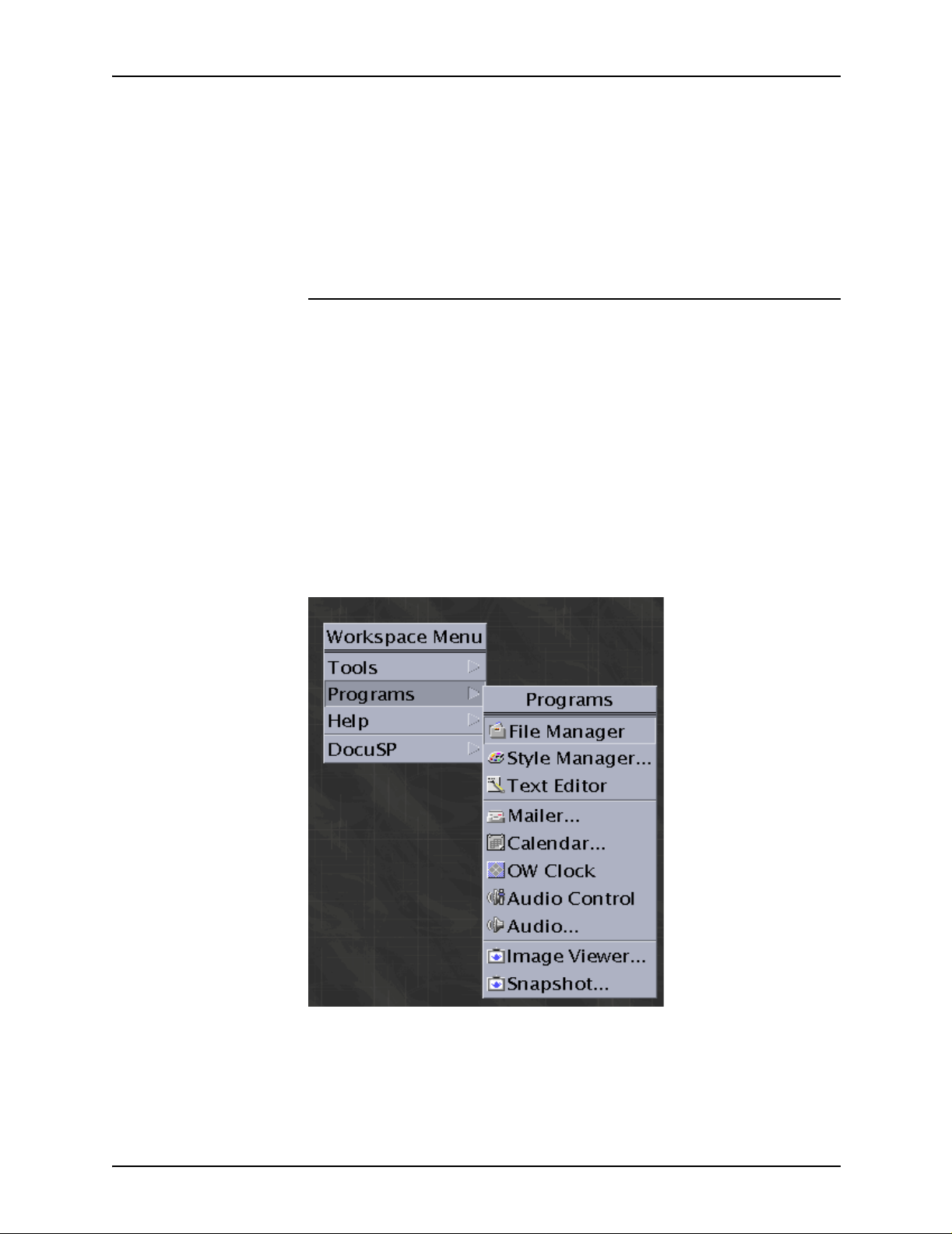
PDL principles and procedures
1. Identify the source media and data format.
2. Design the layout of your print job.
3. Build forms for the job, if necessary.
4. Identify logical processing requirements.
5. Determine whether you will use catalogs.
Short JSL coding procedure
The fastest and easiest way to create a JSL is to build it from an
existing one, such as the default JSL (named DFAULT.JS L),
provided with your system software. The following steps
describe how to create a JSL “the short way.”
1. Open a Text Edi to r win dow by foll owing these steps:
a. On the controller screen, right-click in the background to
b. From the Workspace menu, select [Programs]. The
display the Workspace menu.
Programs pull-down menu op ens beside the Works pace
menu.
Figure 1-9. W ork spa ce and Programs menus
1-50 Using LCDS Print Description Language
Page 79
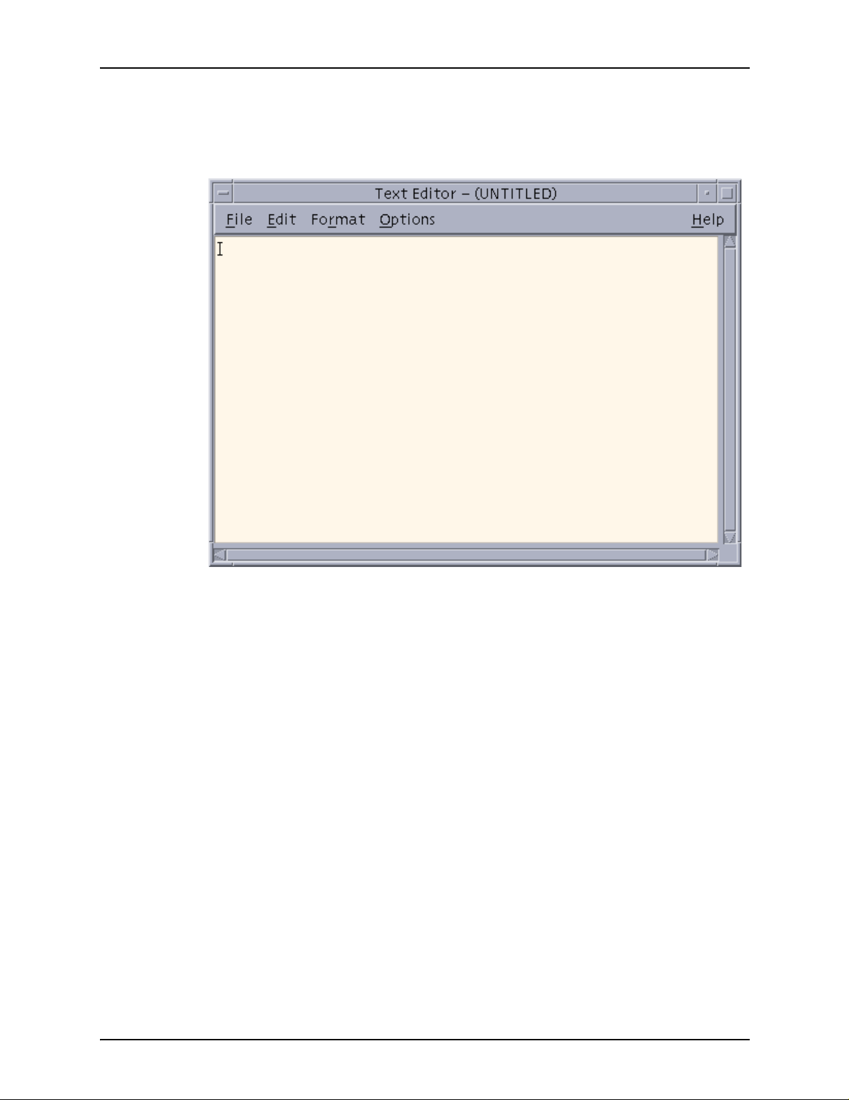
PDL principles and procedures
c. From the Programs menu, select [Text Editor]. A Text
Editor window opens.
Figure 1-10. Text Editor window
2. Bring the default JSL (stored in the “lcds” folder on the
system disk) into the Text Editor, using the following
procedure.
a. From the File menu on the Text Editor menu bar, select
[Include...]. The Text Editor – Include a File window
opens.
Using LCDS Print Description Language 1-51
Page 80

PDL principles and procedures
Figure 1-11. Text Editor – Include a File window
b. In the [Enter path or folder name:] text field at the top of
the Include a File window, enter one of the following
directory paths and press <Return>.
/opt/XRXnps/resources/lcds/
or
/var/spool/XRXnps/resources/lcds/
NOTE: The file and folder names are case–sensitive. Be
sure to enter the directory path exactly as it is shown
above, with regard to uppercase and lowercase letters.
Remember to include the slashes (/) at the beginning and
end.
c. A list of files app ears in the Files field below the te xt bo x in
which you entered the path to the folder. Scroll through
the file list until you locate the file called DFAULT.JSL.
This is the default JSL. (You can also use ONLINE.JSL, if
you are creating the JSL for an online job.)
1-52 Using LCDS Print Description Language
Page 81

PDL principles and procedures
d. Click the file name DFAULT.JSL, then click [OK]. The
default JSL is displayed in the Text Editor window.
3. Using the default JSL as a base, enter any changes,
additional commands or parameters, and deletions that you
need to make in order to construct your new JSL.
NOTE: You should consider carefully the ID name that you
enter in the JDL or SYSTEM command (the first lin e of the
JSL), because this id entifier determines the name o f the JD L
file when your new JSL is compiled.
The JDL name must be one to six characters in length, not
including the extension (following the dot).
4. When you have completed entering all the desired
commands and parameters, select [Save As] from the File
menu on the Text Editor window menu bar. The Text Editor –
Save As window appears.
Figure 1-12. Save As window
Using LCDS Print Description Language 1-53
Page 82

PDL principles and procedures
5. In the [Enter path or folder name:] text field, enter one of the
following paths to the “lcds” folder:
/opt/XRXnps/resources/lcds/
or
/var/spool/XRXnps/resources/lcds/
NOTE: The file and folder names are case–sensitive. Be
sure to enter the directory path exactly as it is shown above,
with regard to uppercase and lowercase letters. Remember
to include the slashes (/) at the beginning and end.
The “lcds” folder, where the DF A ULT .JSL and all other system
LCDS resource files are stored, is the recommended folder
for storing your JSLs. You have write access to this folder,
which means you can add files and create new folders within
it.
6. Enter the name of your new JSL in the [Enter file name:] text
field at the bottom of the Text Editor – Save As window.
Following are some rules for JSL names:
• The name must end with the .JSL file extension.
• The name must be one to six characters in length (not
including the .JSL extension).
CAUTION
Be sure to give a new name to the JSL file that you have
created. Otherwise, your new JSL may overwrite the default
JSL in the “lcds” folder. (Overwriting can occur if you access
the default JSL by selecting [Open] from the File menu on the
Text Editor window instead of [Include]. Refer to step 7 of this
procedure.)
• Recommended:
It is a good idea to use the same name for the JSL that
you specified in the JDL or SYSTEM command at the
beginning of the JSL coding. If the two names are the
same, the JSL file name can be easily determined from
the JDL file name in the future.
7. Click [OK]. Your new JSL is stored on the system disk. You
can now close the Text Editor window.
8. Compile the JSL to create a JDL file. (Refer to “Compiling a
JSL” in this chapter, for the procedure.)
1-54 Using LCDS Print Description Language
Page 83

PDL principles and procedures
Full JSL coding procedure
If you do not want to use an existing JSL as a pattern and you
prefer to build the entire JSL yourself, follow these steps.
1. Open a Text Edi to r win dow by foll owing these steps:
a. On the controller screen, right-click in the background to
display the Workspace menu.
b. From the Workspace menu, select [Programs]. The
Programs pull-down menu op ens beside the Works pace
menu.
Figure 1-13. Workspace and Programs menus
c. From the Programs menu, select [Text Editor]. A Text
Editor window opens.
Using LCDS Print Description Language 1-55
Page 84

PDL principles and procedures
Figure 1-14. Text Editor window
2. In the Text Editor window, code the JDL name, starting at the
left edge of the window workspace.
3. Code the system or JDL level ID commands with their
identifiers.
Recommended:
• Before beginning your system level commands, code a
comment line stating that the fo llo wing entries are system
level commands.
• For each command, at the beginning of the line, enter the
identifier, followed by a colon (:) and the command
keyword. Tab or space over until the cursor is
approximately 20 character spaces from the left edge of
the Text Editor workspace, then enter the first parameter
keyword.
• For each subsequent parameter of the system level
command, tab or space over about 20 character spaces
to enter the parameter, aligning it under the previous
parameter.
• Code the VFU (vertical format unit) first.
1-56 Using LCDS Print Description Language
Page 85

PDL principles and procedures
4. Code the rest of your system level commands (those not
requiring identifiers), to specify your input processing
commands. (Refer to the “Specifying input parameters”
chapter for information on coding these commands.)
Recommended:
For each of these commands, tab or space over about 10
character spaces to enter the command keyword. Then tab
or space ov er until the cursor is about 20 spaces from the left
edge of your Text Editor workspace to begin entering the
parameter keywords.
Figure 1-15. Text Editor window with JSL
showing system level com mands with identifi ers
5. Code the IDEN command at the system level if you plan to
use dynamic job descriptor entries.
6. Identify any dynamic print requirements for DJDEs.
7. If you are using catalog level commands, code them next,
with their identifiers.
Using LCDS Print Description Language 1-57
Page 86

PDL principles and procedures
Recommended: Do the following when you are coding
catalog commands.
• Place a comment on the line above the first CATALOG
• Place the catalog i dentifier, follow ed b y a colon (:) and the
• On the command lines following the catalog identifier line,
8. Code the first JDE identifier, followed by a colon (:) and the
JDE keyword. The JDE name must be one to six characters
long.
NOTE: If the JDE uses a catalog, enter the
INCLUDE=catalogname command following the JDE
identifier on the same line, with the semicolon (;) following the
catalog name. For example:
command line , indicatin g that the f ollo wing command s are
catalog level.
CATALOG keyword, at the left margin, aligned with the
system level identifiers.
tab or space over about 10 character spaces to enter the
rest of the catalog level command keywords.
2: JDE INCLUDE=CATPOW;
Recommended:
• Place a comment on the line above the first JDE
command line , indicatin g that the f ollo wing command s are
JOB or JDE level.
• Tab or space over approximately 10 character spaces to
enter the job identi fier, followed b y a colon (:) and the JD E
keyword.
9. Code the JDE level commands for the first job in the JSL.
Recommended: On the command lines following the JDE
identifier line, ta b or space o v er about 15 character spaces to
enter the rest of the JDE level command keywords for that
job.
10.Repeat steps 8 and 9, above, for each additional JDE that
you want to specify.
11.Enter the END; command to complete the JSL.
12.When you have completed entering all the necessary
commands and parameters, select [Save As] from the File
menu on the Text Editor window menu bar. The Text Editor –
Save As window appears.
1-58 Using LCDS Print Description Language
Page 87
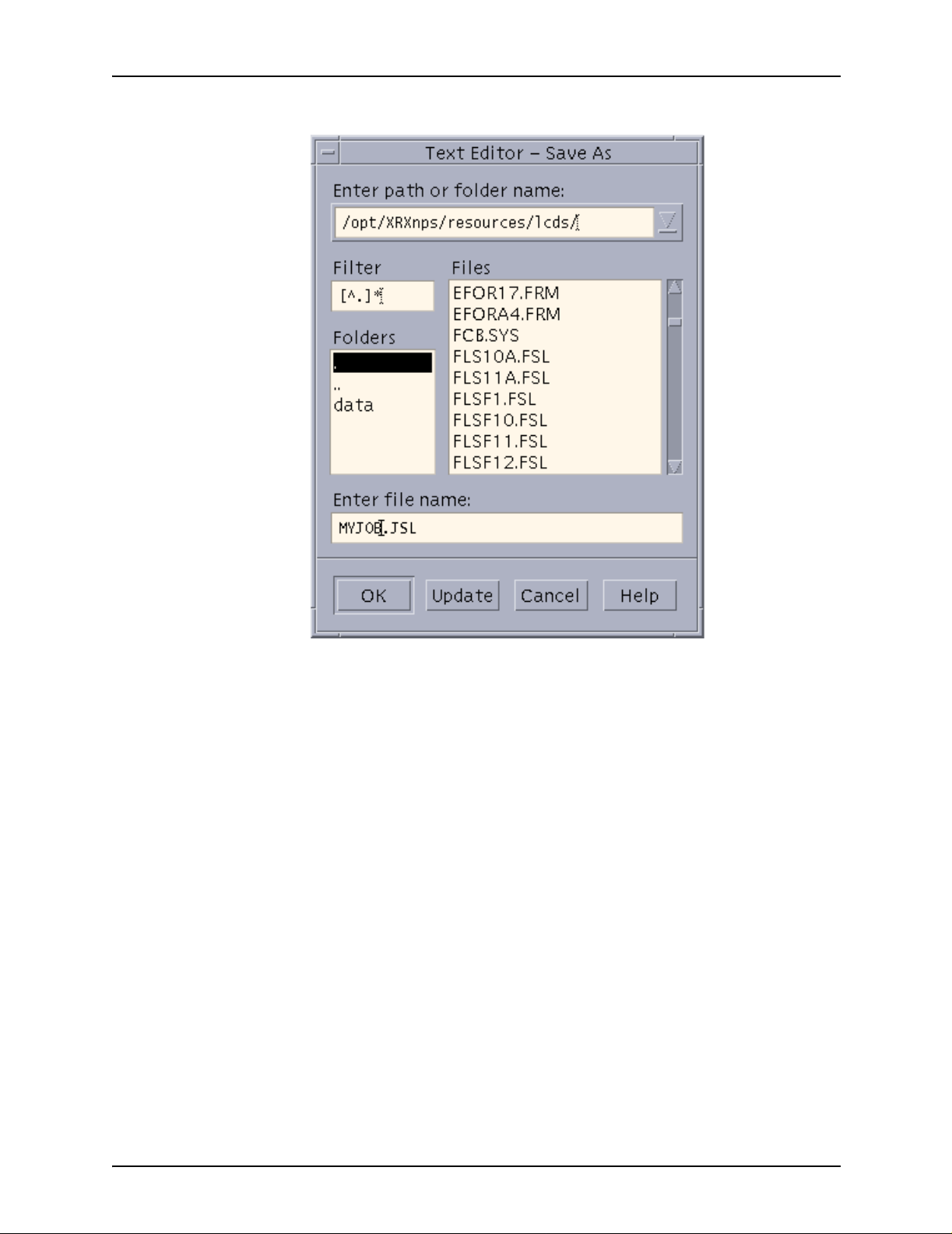
PDL principles and procedures
Figure 1-16. Text Editor – Save As window
13.In the [Enter path or folder name:] text field, enter one of the
following paths to the “lcds” folder:
/opt/XRXnps/resources/lcds/
or
/var/spool/XRXnps/resources/lcds/
The “lcds” folder, where the DF A ULT .JSL and all other system
LCDS resource files are stored, is the recommended folder
for storing your JSLs. You have write access to this folder,
which means you can add files and create new folders within
it.
14.Enter the name of your new JSL in the [Enter file name:] text
field at the bottom of the Text Editor – Save As window.
Following are some rules for JSL names:
Using LCDS Print Description Language 1-59
Page 88

PDL principles and procedures
Be sure to giv e a new name to the JSL file you ha ve created.
Otherwise, y our ne w JSL ma y o ver write the def ault JSL in th e
“lcds” folder. (Overwriting can occur if you access the default
JSL by selecting [Open} from the File menu on the Text
Editor window instead of [Include].
• The name must end with the .JSL file extension.
• The name must be one to six characters in length (not
15.Click [OK]. Your new JSL is stored on the system disk. You
can now close the Text Editor window.
16.Compile the JSL to create a JDL file. (Refer to “Compiling a
JSL,” later in this chapter, for this procedure.)
Sample online JSL
CAUTION
including the .JSL extension).
The following figure shows another example of an online JSL.
Note how comments ar e used to e xpla in and ident ify parts of the
JSL.
Table 1-10. Sample online JSL
ONLINE: JDL;
/* System level commands */
VFU1: VFU ASSIGN=(1,4), ASSIGN=(2,10),
ASSIGN=(3,16), ASSIGN=(4,22),
ASSIGN=(5,28), ASSIGN=(6,34),
ASSIGN=(7,40), ASSIGN=(8,46),
ASSIGN=(9,66), ASSIGN=(10,52),
ASSIGN=(11,58), ASSIGN=(12,64), TOF=4,
BOF=66;
/* Tables and criteria */
T1: TABLE MASK='?', CONSTANT='HE?DE?PAGE';
C1: CONSTANT=(1,10,EQ,T1), LINENUM= (1,10);
T2: TABLE CONSTANT='TRAILER PAGE';
C2: CRITERIA CONSTANT=(0,12,EQ,T2), LINENUM=(1,10);
T3: TABLE CONSTANT='EOJ';
C3: CRITERIA CONSTANT=(0,3,EQ,T3), LINENUM=(1,20)
1-60 Using LCDS Print Description Language
Page 89

PDL principles and procedures
Table 1-10. Sample online JSL (Continued)
T4: TABLE CONSTANT='// JOB';
C4: CRITERIA CONSTANT=(0,6,EQ,T4), LINENUM=(1,20);
T5: TABLE CONSTANT=(10,'*');
C5: CRITERIA CONSTANT=(0,10,EQ,T5), LINENUM=(50,10);
VOLUME HOST=IBMONL;
LINE PCCTYPE=IBM3211, VFU=VFU1,
FCB=IGNORE;
ACCT USER=(TRAY);
IDEN PREFIX='DJDE', SKIP=7, OFFSET=2,
OPRINFO=YES;
/* Job level commands */
/* Jobs with no banner pages */
DFLT: JOB;
/* Jobs with header pages only */
HDRP: JOB;
BANNER TEST=C1, HCOUNT=2, TCOUNT=0;
/* Jobs with trailer pages only */
TRLP: JOB;
BANNER TEST=C2, HCOUNT=0, TCOUNT=3;
/* Jobs with both header and trailer pages */
BOTH: JOB INCLUDE=catname;
BANNER TEST=(C1 OR C2), HCOUNT=2, TCOUNT=3;
/* Other jobs */
EOJ: JOB;
BANNER TEST=C3, TCOUNT=1;
JOB: JOB;
POWER: JOB;
BANNER TEST=C5, HCOUNT=2;
END;
Using LCDS Print Description Language 1-61
Page 90

PDL principles and procedures
Sample offline JSL
The following figure shows an example of an offline JSL. Note
how comments are use d to e x plai n and iden tify parts of the JSL.
NOTE: This JSL contains some highlight color commands.
These commands are processed by the DP EPS, but all printing
is in monochrome.
Table 1-11. Sample offline JSL
JDLHLC: JDL;
/* System (ID) level commands */
VFU1: VFU ASSIGN=(1,5), ASSIGN=(2,10),
ASSIGN=(3,15), TOF=5, BOF=66;
PDE1: PDE BEGIN=(175DOTS, 300XDOTS),
FONTS=(UN110E,PR110E,PR124B);
PDE2; PDE BEGIN=(0.725IN, 1.000IN),
FONTS=(L0512C,L05SCA,L05ITA),
PMODE=LANDSCAPE;
IDR1: IDR ILIST=(‘RED’,‘BLACK’,‘PINK’);
/***IDFAULT=’RED’***/
IDR2: IDR ICATALOG=XEROX, PALETTE=’PICTORIAL’,
ILIST=(‘BLACK’,‘RED’,‘PALE PINK’);
/*IDFAULT=’BLACK’*/
/* Tables and criteria */
T1: TABLE CONSTANT=(A'REPORT');
C1: CRITERIA CONSTANT=(2,6,EQ,T1);
/* System level commands */
VOLUME HOST=IBMOS, CODE=ASCII;
BLOCK LENGTH=2048;
RECORD LENGTH=135, STRUCTURE=VB, LTHFLD=2,
ADJUST=0, FORMAT=BIN, PREAMBLE=3;
LINE DATA=(1,132), PCCTYPE=IBM1403;
PCC=(0,NOTRAN),OVERPRINT=(PRINT,NODISP),
VFU=VFU1;
IDEN PREFIX=A'DJDE', SKIP=6, OFFSET=2,
OPRINFO=YES;
1-62 Using LCDS Print Description Language
Page 91

Table 1-11. Sample offline JSL (Continued)
RSTACK TEST=(C1), DELIMITER=YES;
ACCT USER=TRAY;
/******* Catalog level commands *******/
CATPOW; CATALOG;
VOLUME HOST=IBMOS, CODE=EBCDIC;
BLOCK LENGTH=2048, PREAMBLE=6, LTHFLD=2,
FORMAT=BIN, OFFSET=4;
RECORD LENGTH=135, STRUCTURE=VB, PREAMBLE=2,
LTHFLD=2, FORMAT=BIN, OFFSET=0,
ADJUST=3;
CATGRP: CATALOG;
VOLUME HOST=GRASP, CODE=EBCDIC
PDL principles and procedures
BLOCK LENGTH=4096, PREAMBLE=0, ZERO=YES;
RECORD LENGTH=135, STRUCTURE=VB, PREAMBLE=1,
LTHFLD=1, FORMAT=BIN, OFFSET=0,
ADJUST=2;
/******* Job or JDE level commands *******/
1: JDE;
OUTPUT IDR=IDR1, NUMBER=(1,1,0,1,’BLACK’),
FORMAT=PDE1, LOGO=(SIG1, 1.5 IN,6.0 IN);
2: JDE; INCLUDE=CATPOW;
VOLUME HOST=UNIVAC, CODE=PEBCDIC;
OUTPUT IDR=IDR2, FORMAT=PDE2, IDFAULT=2,
FORMS=STMT3;
ABNORMAL ERROR=CONTINUE, IMISMATCH=CONTINUE;
3: JDE; INCLUDE=CATGRP;
OUTPUT COPIES=5, IDFAULT=’BLACK’;
DFLT: JDE;
END;
Using LCDS Print Description Language 1-63
Page 92
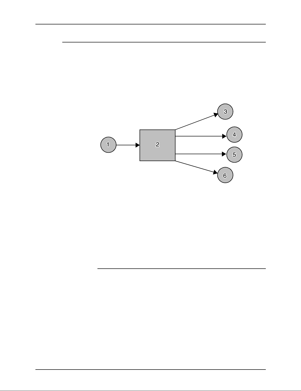
PDL principles and procedures
Compiling a JSL
The second part of creating the JSL is compiling it. Each JSL file
must be compiled (converted) into an object file (Job Descriptor
Library or JDL) before it can be read b y the syst em to print a job.
The Xerox Job Description Compiler (XJDC) software on your
controller performs this conversion. The process is diagrammed
below.
Rules for invoking
the XJDC compiler
Figure 1-17. PDL compilation
1. JSL
2. XJDC (PDL compiler)
3. CME file (Copy Modification Entry)
4. JDL file (Job Descriptor Library [a compiled JSL])
5. PDE file (Print Descriptor Entry, or format)
6. STK file (STOCKSET file)
Compiling procedure
After you have finished entering all the commands for your JSL,
including the last END; command, and saved the .JSL file in the
“lcds” folder, you can begin the compilation proce ss.
The command that invokes the XJDC compiler has some
different syntax rules from the PDL commands that you used to
create the JSL. Keep in mind the following rules when you enter
this command:
1-64 Using LCDS Print Description Language
Page 93
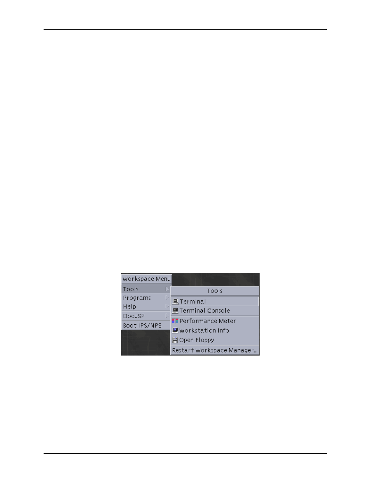
PDL principles and procedures
• Do not omit any slashes (/ ). These symbols separ ate diff erent
directory levels of folders in the UNIX file system. The slash
at the beginning of the command is actually the identifier or
“name” of the parent (root) directory of the file system.
• Enter all command text in lowercase letters.
NOTE: This rule does not apply to UNIX file and folder
names that contain uppercase letters. Be sure to enter any
file or folder names exactly the way they appear in the
directory. (For example, if you enter the “XRXnps” folder
name as “xrxnps,” the system cannot find it.)
• Leave spaces only where the command syntax shows them;
do not add any spaces where they are not indicated.
• Italics indicate variables that you must specify. For example,
when entering a command, you would replace the word
filename with the actual name of the file.
Follow these steps to compile a JSL:
1. On the controller workspace, open a Terminal window by
following these steps:
a. Right click in the controller workspace (screen
background) to display the Workspace menu.
b. From the Workspace menu, select [Tools]. The Tools
menu is displayed next to the Workspace menu.
Figure 1-18. Selecting [Tools] from the Workspace
menu
c. Select [Terminal] from the T ools menu. A Terminal window
opens.
Using LCDS Print Description Language 1-65
Page 94
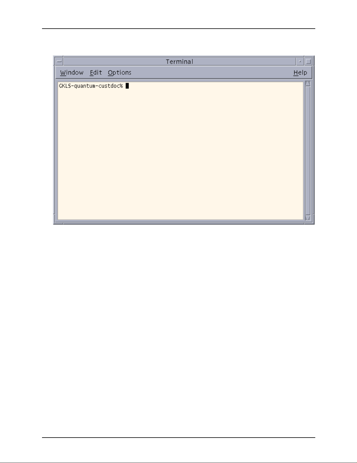
PDL principles and procedures
Figure 1-19. Terminal window with % prompt
displayed
2. Move the pointer on to the Terminal window. A blinking cursor
should be visible next to the prompt (a % sign, sometimes
preceded by the name of your system).
3. At the % prom pt, e nter the following command to compi le the
JSL (be sure to leave spaces where they are indicated).
/opt/XRXnps/bin/xjdc options /opt/XRXnps/resources/lcds/JSLNAME.JSL
The options variable may be either omitted or replaced with
one or more of the options that are shown on the following
table. Options may be specified in any order.
You may shorten the option name to its first three characters
(shown in uppercase in the following table).
The first option must be preceded by a hyphen. When you
specify multiple options , y ou m ust se par ate the m b y commas
(refer to the following example).
Example:
/opt/XRXnps/bin/xjdc –NOT,LAB,REP /opt/XRXnps/resources/lcds/MYJOB.JSL
1-66 Using LCDS Print Description Language
Page 95

PDL principles and procedures
Table 1-12. xjdc command options
Option Definition
COMpile Compiles the JSL with printed sheets.
SCAn Scans the JSL only.
PRInt Generates a printed JSL.
NOPrint Generates a printed JSL only when it contains errors.
REPlace Specifies that an existing JDL file may be replaced by a new output file of the
same name. This is the default.
NOReplace Specifies that, if the new JSL has the same name as an existing one, the old
file is retained as a backup file and is given a “.backup” extension. REPLACE is
the default.
SINglebyte Specifies use of single byte character code and printer carriage control
translation files.
DOUblebyte Specifies use of double byte character code and printer carriage control
translation files.
TRUncate Restricts command lines in the JSL to the first 72 characters.
NOTruncate Accepts JSL command lines that are longer than 72 characters.
LABel Generates a 128 byte Xerox standard label.
NOLabel Suppresses the 128 byte Xerox standard label.
DISplay Displays all XJDC messages.
NODisplay Suppresses all XJDC messages.
Vx Software version number.
x = 10, 2, 35, 3615, 37, 38, 39, 40, 50, 3A, or M10
For DP EPS, the version number is M10.
PAPersize=s
(VM10 only)
DATe = d Specifies the date format.
PAGinate=n Specifies the number of lines per page.
Specifies the size of paper the job should print on.
s = USLEGAL, USLETTER, or A4
d = US or EUROPEAN
n = 0 or 5 through 999 (0 specifies no pagination.)
OUTpath=p Specifies the base directory path for output files.
p = / foldername1 / foldername2 /...
The default is the current directory.
Using LCDS Print Description Language 1-67
Page 96

PDL principles and procedures
If the JSL compiles correctly with no errors, the JDL object
file is created from the JSL, and a message is displayed in
the Terminal window, indicating that the compilation was
successful.
The system places the newly created JDL file (along with the
.LST and .RSC files that are c reate d at th e sam e ti me) in the
“lcds” resources folder where your JSL is located.
4. If the JSL doe s not com pile correctly, correct any errors in the
JSL and recompile it.
Files produced by the compilation procedure
When XJDC compiles a JSL, it produces the following files:
• Object file (JDL): The JDL, which contains all the
information from the JSL, but in a format the system can
read. If the JSL was compiled successfully, the object file, or
Job Descriptor Library file, is created. The JDL file name is
the identifier that is specified b y th e JDL comma nd that starts
the JSL. It has a .JDL extension.
NOTE : If you compile on e of the othe r file types (othe r than a
JSL) that are supported by the XJDC compiler, the file
extension could be .CME, .IDR, .LIB , .PDE, .STK, or .TST. Its
file name is the name that is spe cified b y the first command in
the file; that is, the CME, IDR, LIB, PDE, STK, or TST
command.
• JSL Source Listing file: Shows the JSL as y ou code d it, but
with the lines and columns numbered. Also indicates the
location of any errors, along with messages explaining the
errors. The Source Listing file name is th e same as the JSL
name, except that it has a .LST extension.
• Resource Listing file: Contains a list of the resources that
are specified in the JSL, such as font names and form
names. The Resource Listing file name is the same as the
JSL name, except that it has a .RSC extension.
• Log file: Contains all messages that were displayed on the
screen during compiling. This file is appended each time
XJDC is invoked, and it is placed in the following directory:
/opt/XRXnps/XRXxjdc/data/
The Log file name is “XJDC.LOG.”
1-68 Using LCDS Print Description Language
Page 97

PDL principles and procedures
Correcting errors in a JSL
If errors are encountered in a JSL while it is being compiled, the
following message appears in the Terminal window:
**********JSL CONTAINS ERROR(S)**********
Figure 1-20. Terminal window displaying compiling
messages for a JSL with errors
The system does not create a .JDL file in the “lcds” fo lder, but it
does create a .LST file, which shows where the errors are.
1. Open and inspect the .LST file to locate the errors that
prevented the JSL from compili n g.
To open a .LST file:
a. Open a UNIX Text Editor window. (Refer to “Full JSL
coding procedure,” earlier in this chapter, for instructions.)
b. From the File menu on the Text Editor window, select
[Open] to display the Text Editor – Open a File window.
Using LCDS Print Description Language 1-69
Page 98

PDL principles and procedures
Figure 1-21. Text Editor – Open a File window
c. In the Folders field, double-click the name of each of the
folders that comprise the path to the “lcds” folder, in the
order shown below:
/opt/XRXnps/resources/lcds
d. In the Files field of the Open a File window, click the name
of the .LST file for the JSL you attempted to compile; or
In the Files text field on the Open a File window, enter the
name of your .LST file. The name syntax is as follows:
JSLNAME.LST
e. Click [OK] on the Open a File window. The .LST file
appears in the text window. This file contains the
following:
• The JSL as you coded it, but with the lines and
columns numbered
• Below each line that contains errors, a message that
explains each error that is on the line
•The <<<<<<<< symbol at the end of each error
message line.
1-70 Using LCDS Print Description Language
Page 99

PDL principles and procedures
Figure 1-22. A .LST file for a JSL containing errors
2. Open another Text Editor window an d display your JSL in this
new window. (The procedure for displaying the JSL is
described under “Opening a file in the Text Editor,” above.)
3. Enter the indicated corrections to your JSL, referring to the
.LST file in the other Text Editor window as needed.
4. On the Terminal window, recompile the corrected JSL, using
the compiling procedure that is described earlier in this
section.
Using LCDS Print Description Language 1-71
Page 100

PDL principles and procedures
Dynamic job descriptor entries (DJDEs)
Dynamic job descriptor entries (DJDEs) are par a m ete rs
embedded within the input data stream. DJDEs modify the
printing environ m ent established by a job descriptor entry (JDE)
as the job is printing. Dynamic job descriptor entry processing
allows certain JDE parameters to be chan ge d for individual
pages or records.
The IDEN command, coded in a JDE, notifies the system that
DJDE records are included in the input data stream, specifies
where the DJDEs commands are embedded in the data record,
and specifies how to identify the DJDE records.
Benefits of using DJDEs
There are several reasons to use DJDEs to change job
parameters:
• The printing system does not need to stop between reports
nor does it require operator intervention. The operator starts
a job on the printing system and typically returns to the
system for minor operational activity only.
• Forms may be changed on specific pages.
• Many v ariations o n VFU channe l, margin , Top Of Form (TOF)
and Bottom Of Form (BOF) assignments may be applied to
reports as they are creat ed instead of being stored in the
printing system in JDL files. This dynamic processing
reduces the number of JDEs that need to be maintained.
• DJDEs can be used to satisfy unusual processing
requirements more easily.
• Varying numbers of copies can be gene ra ted automati cally
with routing or distribution notification sent to the operator.
• Print resources (such as forms and fonts) or nonprint data
can be downloaded onto the system disk through the print
data stream.
1-72 Using LCDS Print Description Language
 Loading...