Xerox 3030 Service manual

4 (2)

Notes:

Search

-

5/93

xii

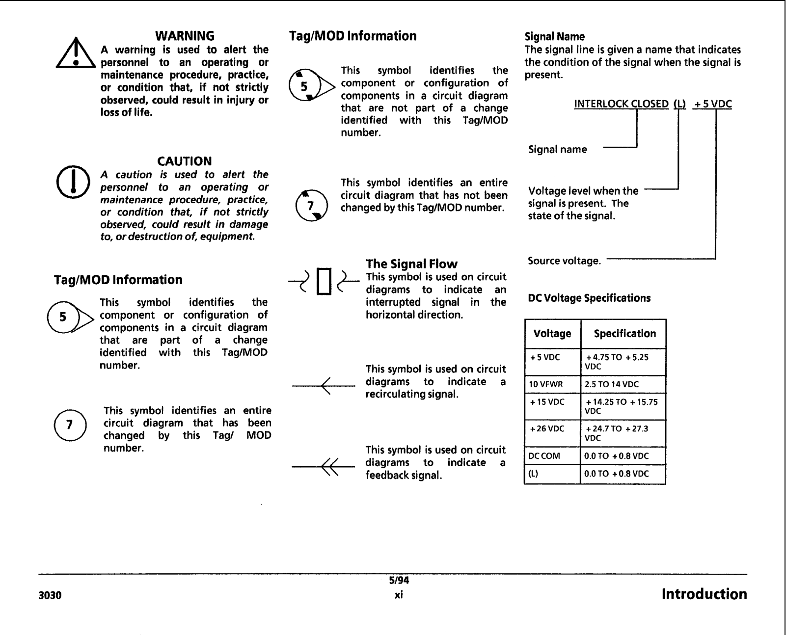
WARNING

A warning is used to alert the personnel to an operating or maintenance procedure, practice, or condition that, if not strictly observed, could result in injury or loss of life.

TagIMOD Information

This symbol identifies the component or configuration of components in a circuit diagram that are not part of a change identified with this Tag/MOD number.

Signal Name

The signal line is given a name that indicates the condition of the signal when the signal is present.

CAUTION

A caution is used to alert the personnel to an operating or maintenance procedure, practice, or condition that, if not strictly observed, could result in damage to, or destructionof, equipment.

TagIMOD Information

This symbol identifies the component or configuration of

-components in a circuit diagram that are part of a change identified with this TagIMOD number.

This symbol identifies an entire circuit diagram that has been changed by this Tag/ MOD number.

This symbol identifies an entire circuit diagram that has not been changed by this TagIMOD number.

The Signal Flow

++

This symbol is used on circuit diagrams to indicate an interrupted signal in the horizontaldirection.

This symbol is used on circuit diagrams to indicate a recirculatingsignal.

This symbol is used on circuit diagrams to indicate a feedback signal.

5/94

Voltage level when the signal is present. The state of the signal.

Source voltage.

I


DCVoltage Specifications


1 Voltage 1

Specification I


+5 VDC

+4.75 TO +5.25


+26 VDC

+24.7 TO +27.3

I DCCOM

VDC

I0.0 TO +O.8 VDC I

(L)

0.0 TO +0.8 VDC

3030

xi

Introduction

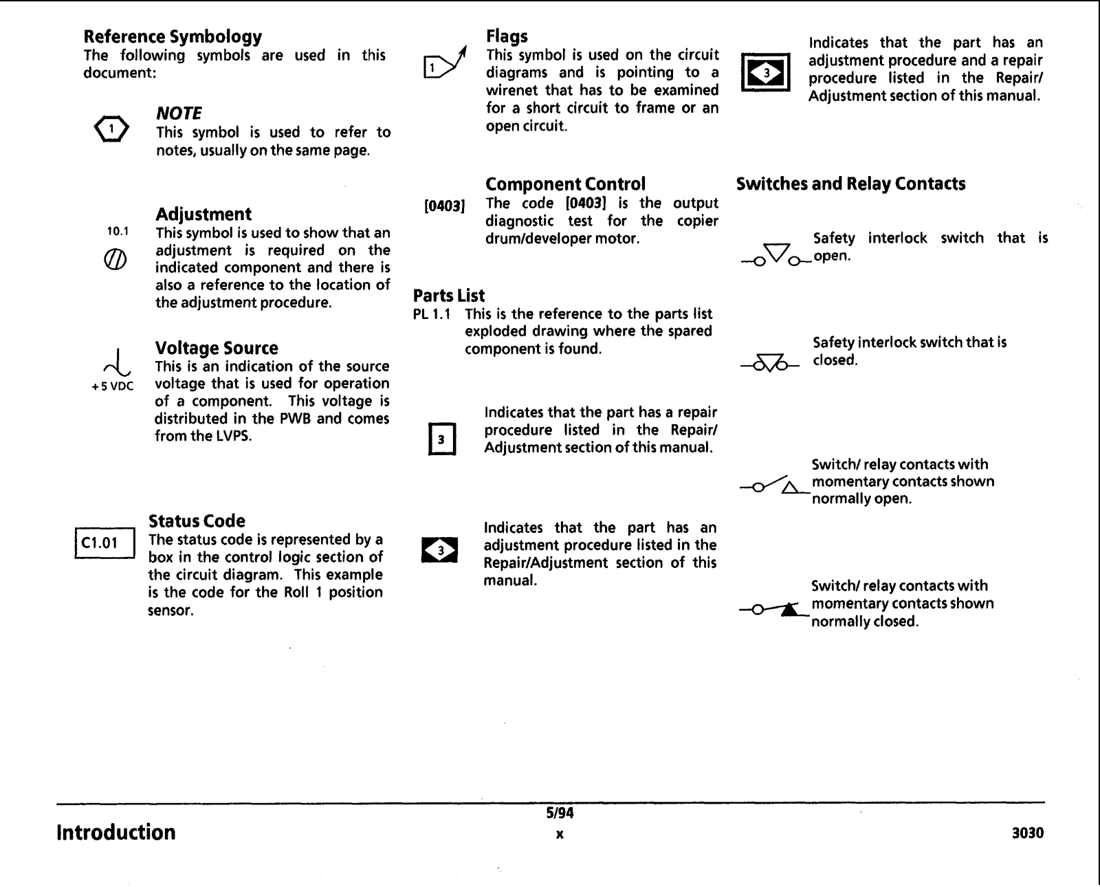
Reference Symbology

The following symbols are used in this document:

Q

NOTE

This symbol is used to refer to


notes, usually onthe same page.

Adjustment

10.1This symbol is used to show that an

adjustment i s required on the 0 indicated component and there is also a reference to the location of

the adjustmentprocedure.

rL

Voltage Source

This is an indication of the source

+5 VDC

voltage that is used for operation


of a component. This voltage is


distributed in the PWB and comes


from the LVPS.

Status Code

The status code is represented by a box in the control logic section of the circuit diagram. This example is the code for the Roll 1 position sensor.

Introduction

Flags

This symbol is used on the circuit diagrams and is pointing to a wirenet that has to be examined for a short circuit to frame or an open circuit.

Component Control

[0403] The code 104031 is the output diagnostic test for the copier drumldeveloper motor.

Parts List

PL 1.1 This is the reference to the parts list exploded drawing where the spared component is found.

lndicates that the part has a repair procedure listed in the Repair/ Adjustment sectionof this manual.

lndicates that the part has an adjustment procedure listed in the RepairlAdjustment section of this manual.

5/94 x

lndicates that the part has an lol adjustment procedure and a repair procedure listed in the Repair1 Adjustment section of this manual.

Switches and Relay Contacts

Safety interlock switch that is 4Vs open.

Safety interlockswitchthat is

&&closed.

Switch/relay contactswith /&momentary contactsshown

normally open.

Switch1relaycontactswith momentarycontactsshown normallyclosed.

3030

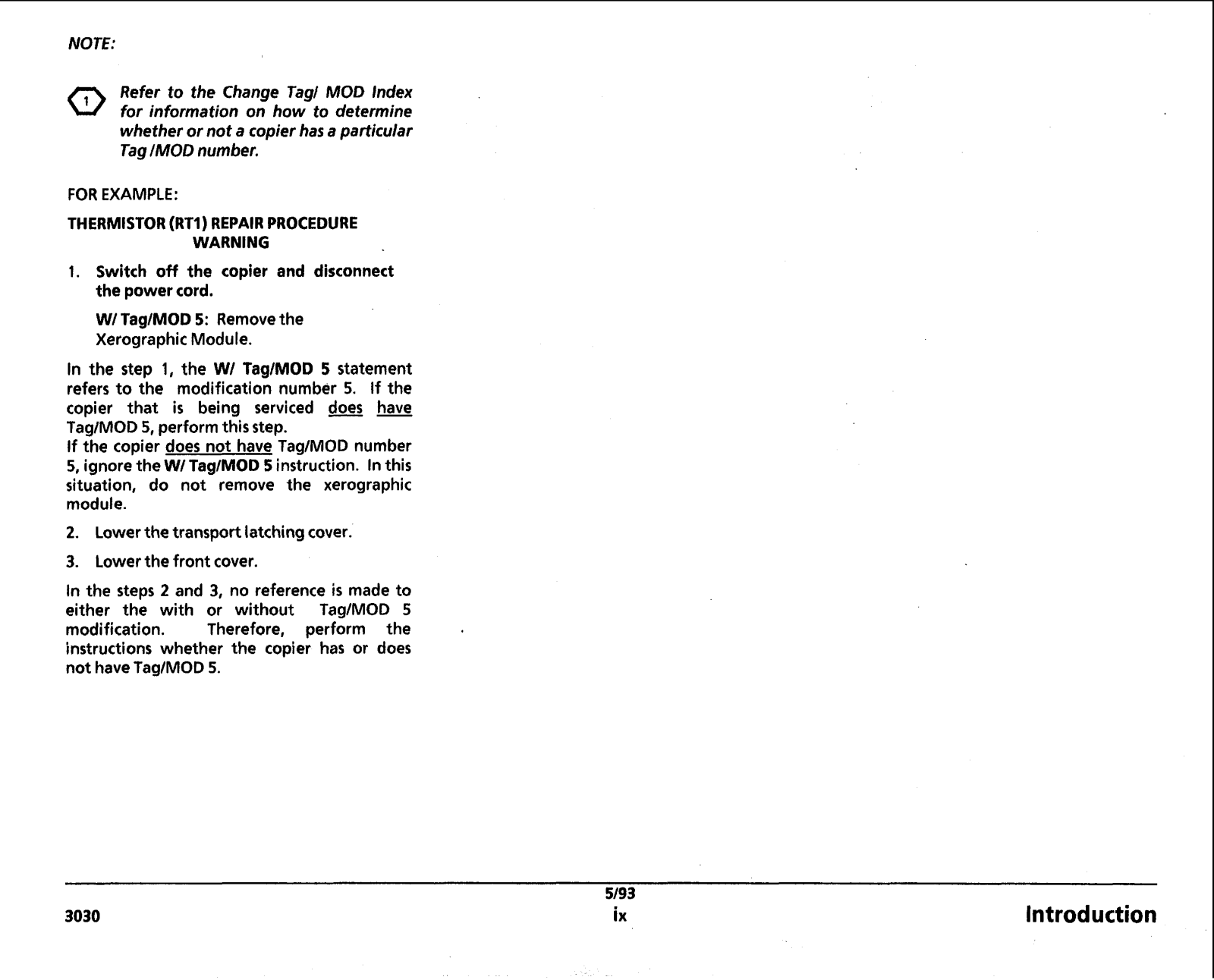
NOTE:

Refer to the Change Jag1 MOD Index for information on how to determine whether or not a copier has a particular Tag/MOD number.

FOR EXAMPLE:

THERMISTOR (RT1) REPAIR PROCEDURE

WARNING

1.Switch off the copier and disconnect the power cord.

W1TaglMOD 5: Removethe Xerographic Module.

In the step 1, the WI TagIMOD 5 statement refers to the modification number 5. If the copier that is being serviced does have TaglMOD 5, perform this step.

If the copier does not have TaglMOD number 5, ignore the W1TaglMOD 5 instruction. Inthis situation, do not remove the xerographic module.

2.Lower the transport latching cover.

3.Lowerthe front cover.

In the steps 2 and 3, no reference is made to either the with or without TagIMOD 5 modification. Therefore, perform the instructions whether the copier has or does not haveTaglMOD 5.

5/93

3030

ix

Introduction

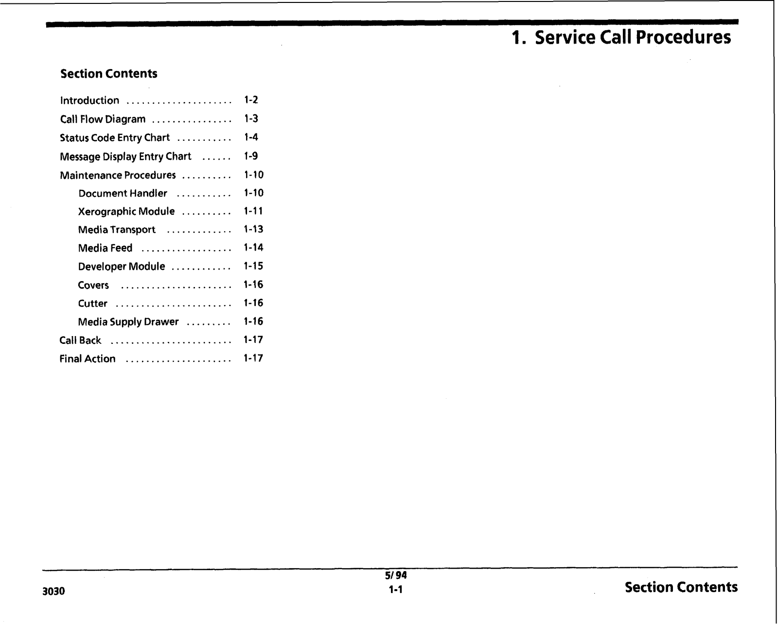
Section Contents

Introduction .....................

1-2

Call Flow Diagram ................

1-3

Status Code Entry Chart ...........

1-4

Message Display Entry Chart ......

1-9

Maintenance Procedures ..........

1.10

Document Handler ...........

1-10

Xerographic Module ..........

1-11

Media Transport .............

1-13

Media Feed ..................

1-14

Developer Module ............

1-15

Covers ......................

1.16

Cutter .......................

1-16

Media Supply Drawer .........

1-16

Call Back ........................

1-17

Final Action .....................

1-17

51 94

3030

1-1

Service Call Procedures

Section Contents

Xerox 3030 Service manual

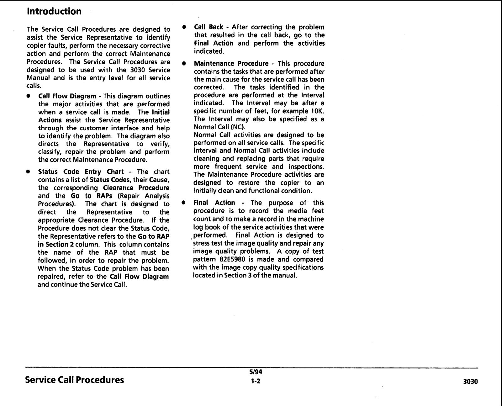
Introduction

The Service Call Procedures are designed t o assist the Service Representative t o identify copier faults, perform the necessary corrective action and perform the correct Maintenance Procedures. The Service Call Procedures are designed t o be used with the 3030 Service Manual and is the entry level for all service calls.

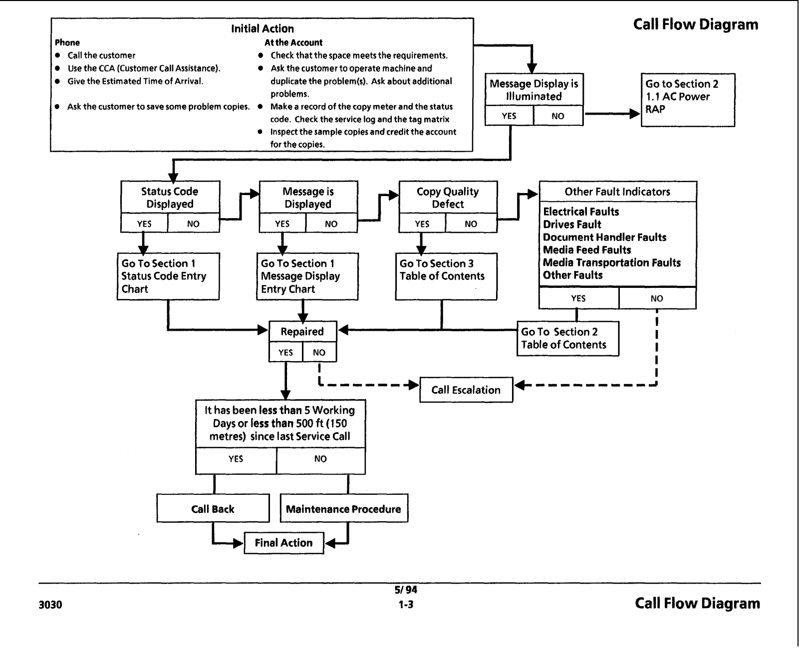
Call Flow Diagram - This diagram outlines the major activities that are performed when a service call is made. The Initial Actions assist the Service Representative through the customer interface and help t o identify the problem. The diagram also directs the Representative to verify, classify, repair the problem and perform the correct Maintenance Procedure.

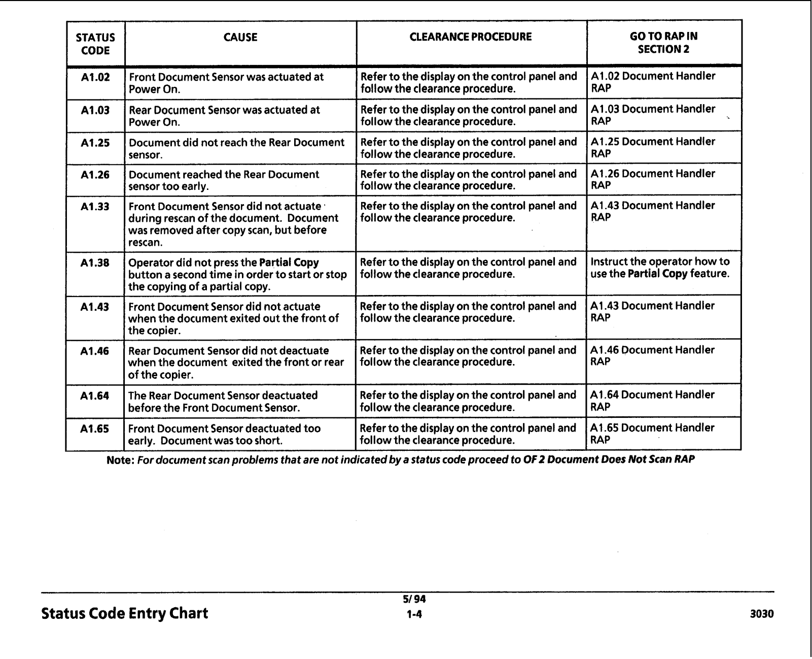
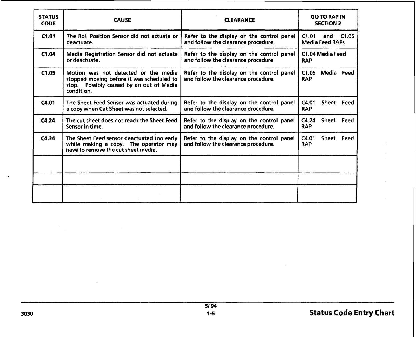
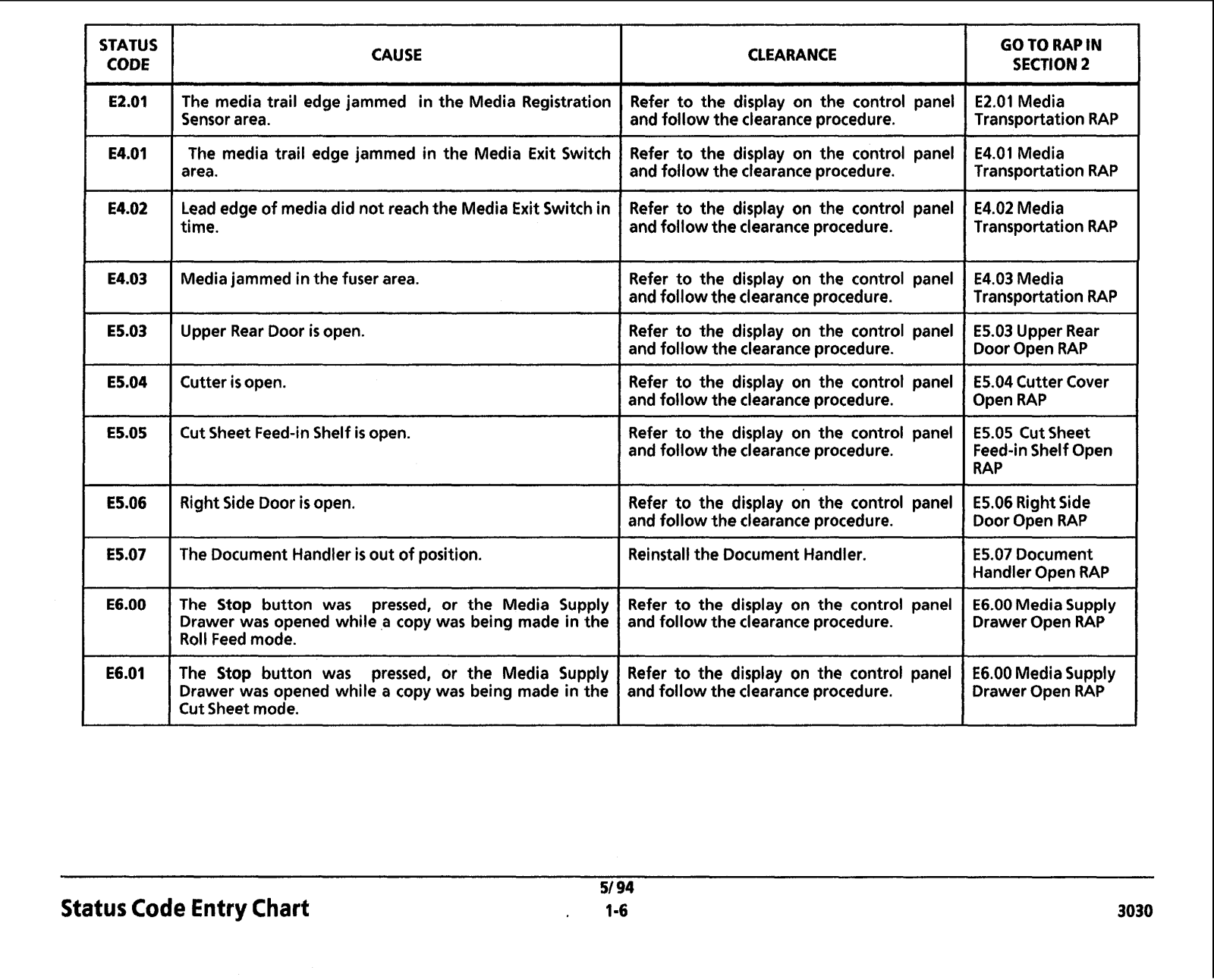
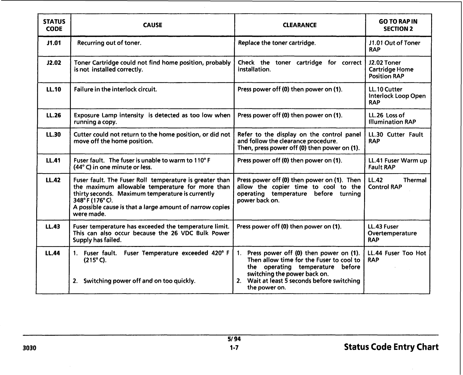
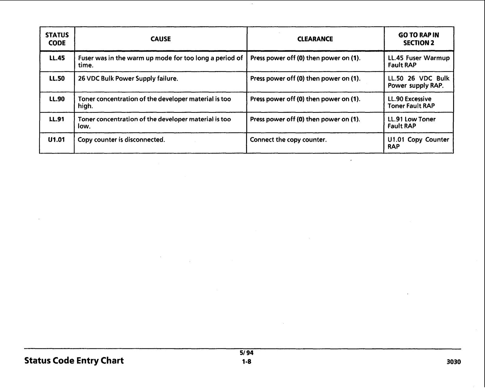
Status Code Entry Chart - The chart contains a list of Status Codes, their Cause, the corresponding Clearance Procedure and the Go t o RAPS (Repair Analysis Procedures). The chart is designed t o direct the Representative t o the appropriate Clearance Procedure. If the Procedure does not clear the Status Code, the Representativerefers t o the Go t o RAP in Section 2 column. This column contains the name of the RAP that must be followed, in order t o repair the problem. When the Status Code problem has been repaired, refer t o the Call Flow Diagram and continue the Service Call.

Service Call Procedures

Call Back - After correcting the problem that resulted i n the call back, go t o the Final Action and perform the activities indicated.

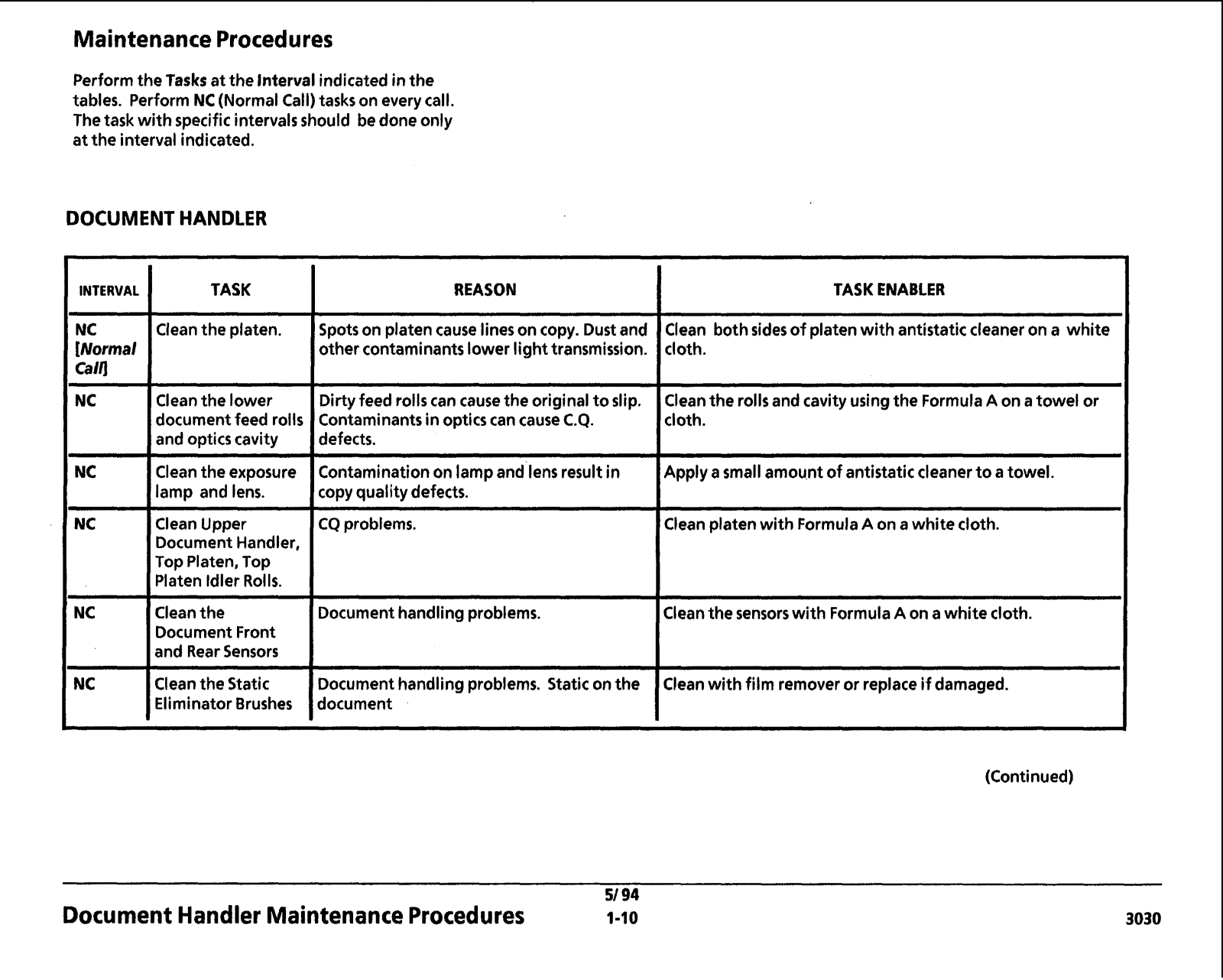
Maintenance Procedure - This procedure contains the tasks that are performed after the main cause for the service call has been corrected. The tasks identified in the procedure are performed at the Interval indicated. The Interval may be after a specific number of feet, for example 10K. The Interval may also be specified as a Normal Call (NC).

Normal Call activities are designed t o be performed on all service calls. The specific interval and Normal Call activities include cleaning and replacing parts that require more frequent service and inspections. The Maintenance Procedure activities are designed t o restore the copier t o an initially clean and functional condition.

Final Action - The purpose of this procedure is to record the media feet count and t o make a record in the machine log book of the service activities that were performed. Final Action is designed to stress test the image quality and repair any image quality problems. A copy of test pattern 82E5980 is made and compared with the image copy quality specifications located in Section 3 of the manual.

5/94


1-2

3030

Initial Action

Phone

At the Account

Callthe customer

Check that the space meetsthe requirements.

Usethe CCA (Customer CallAssistance).

Ask the customerto operate machineand

Give the EstimatedTime of Arrival.

duplicate the problem(s). Ask about additional


problems.

Ask the customer to save some problem copies.

Make a record of the copy meter and the status


code. Check the service log and the tag matrix


* Inspectthe sample copies andcredit the account

for the copies.

Call Flow Diagram

Message Display is

Go t o Section 2

Illuminated

1.1 AC Power

*

Status Code

Message is

,+

Copy Quality

Other Fault Indicators

Displayed

Displayed


Defect

Electrical Faults


L


d


YES

YES

NO

YES

NO

Drives Fault

NO


-


Document Handler Faults


Media Feed Faults

Go To Section 1

Go To Section 1


Go To Section3

Media Transportation Faults

Status Code Entry

Message Display


Table of Contents

Other Faults

Chart


Entry Chart


-

YES

NO

I

I


-Repaired

1G O O Section 2 I

I

YES NO


Table of Contents

I

I

I I

v

1 I I I - I -

Ithas been lessthan 5 Working Daysor less than 500 ft (1 50 metres) since last Service Call

I

Call lack

I IMaintenanceProcedure I


51 94

3030

1-3

Call Flow Diagram

STATUS

CAUSE

CLEARANCE PROCEDURE

CODE


Front DocumentSensor was actuated at

Power On.

Rear Document Sensor was actuated at

Power On.

Documentdid not reachthe Rear Document sensor.

Document reachedthe Rear Document sensor too early.

Front Document Sensor did not actuate during rescanof the document. Document was removed after copy scan, but before rescan.

Operator did not pressthe PartialCopy button a secondtime in order to start or stop the copying of a partialcopy.

-

Front DocumentSensor did not actuate when the documentexited out the front of the copier.

Rear Document Sensor did not deactuate when the document exitedthe front or rear of the copier.

The Rear DocumentSensor deactuated beforethe Front DocumentSensor.

Front DocumentSensor deactuatedtoo early. Documentwas too short.

Status Code Entry Chart

Refer to the display onthe control panel and follow the clearance procedure.

Referto the display onthe control panel and follow the clearance procedure.

Refer to the display onthe control panel and follow the clearance procedure.

Refer to the display on the control panel and follow the clearance procedure.

Refer to the display on the control panel and follow the clearance procedure.

Referto the display onthe control panel and follow the clearance procedure.

Refer to the display onthe control panel and follow the clearance procedure.

Refer to the display onthe control panel and follow the clearance procedure.

Referto the display onthe control panel and follow the clearance procedure.

Referto the display on the control panel and follow the clearance procedure.

codeproceed

51 94

1-4

GOT0 RAPIN

SECTION2

A1.02 Document Handler

I

RAP - - - -

A1.O3 Document Handler


RAP


Al.25 Document Handler


A1.26 Document Handler


A1.43 Document Handler

I

RAP


Instructthe operator how to usethe PartialCopy feature.

R*PIA1.43 Document Handler

Al.46 Document Handler

RAP

Al.64 Document Handler

I

RAP

Al.65 Document Handler

I

RAP

DoesNot Scan RAP


3030

STATUS

CODE

3030

CAUSE

The Roll Position Sensor did not actuate or deactuate.

Media Registration Sensor did not actuate or deactuate.

Motion was not detected or the media stopped moving before it was scheduled to stop. Possibly caused by an out of Media condition.

CLEARANCE

Refer to the display on the control panel and follow the clearance procedure.

Refer to the display on the control panel and follow the clearance procedure.

-- --

- -

--

-

I

GO TO RAP IN


SECTION2


C1.01

and C1.05

Media Feed RAPS

C1.04 Media Feed

RAP

--

Refer to the display on the control panel

C1.05 Media Feed

and follow the clearance procedure.

RAP

The Sheet Feed Sensor was actuated during a copy when Cut Sheet was not selected.

The cut sheet does not reachthe Sheet Feed Sensor intime.

The Sheet Feed sensor deactuated too early while making a copy. The operator may have to remove the cut sheet media.

Refer to the display on the control panel

C4.01

Sheet

Feed

and follow the clearance procedure.

RAP


Refer to the display on the control panel

C4.24

Sheet

Feed

and follow the clearance procedure.

RAP


Refer to the display on the control panel

C4.01

Sheet

Feed

and follow the clearance procedure.

IRAP


5/ 94

Status Code Entry Chart

1-5

I

I


CAUSE


CLEARANCE


IThe media trail edge jammed in the Media Registration

-

- -

--

E2.01

Refer to the display on the control panel


Sensor area.

and follow the clearance procedure.

E4.01

The media trail edge jammed in the Media Exit Switch

Refer to the display on the control panel


area.

and follow the clearance procedure.

E4.02

Lead edge of media did not reachthe Media Exit Switchin

Refer to the display on the control panel


I

and follow the clearance procedure.


Refer to the display on the control panel


Mediajammed inthe fuser area.


and follow the clearance procedure.

E5.03

Upper Rear Door is open.

Refer to the display on the control panel


and follow the clearance procedure.


Cutter is open.

Refer to the display on the control panel


and follow the clearance procedure.


Cut Sheet Feed-inShelf is open.

Refer to the display on the control panel


and follow the clearance procedure.

GO TO RAP IN

SECTION 2

E2.01 Media

TransportationRAP

E4.01 Media

TransportationRAP

E4.02 Media

TransportationRAP

E4.03 Media

TransportationRAP

E5.03 Upper Rear

Door Open RAP

E5.04 Cutter Cover

Open RAP

E5.05 Cut Sheet

Feed-inShelf Open

RAP

Right Side Door is open.


Refer to the display on the control panel

E5.06 RightSide


and follow the clearance procedure.

Door Open RAP

The Document Handler is out of position.


Reinstallthe Document Handler.

E5.07 Document


Handler Open RAP

The Stop button was

pressed,

or the

Media Supply

Refer to the display on the control panel

E6.00 MediaSupply

Drawer was opened while a copy was being made in the

and follow the clearance procedure.

Drawer Open RAP

Roll Feedmode.


-

-

-

-- -

- --


The Stop button

was

pressed, or the

Media Supply

Refer to the display on the control panel

E6.00 MediaSupply

Drawer was opened while a copy was being made in the

and follow the clearance procedure.

Drawer Open RAP

Cut Sheet mode.


Status Code Entry Chart

;TATUS CODE

CAUSE

CLEARANCE

Recurring out of toner.

IReplace the toner cartridge.

Toner Cartridgecould not find home position, probably

Check the toner cartridge for correct

is not installedcorrectly.

installation.

Failureinthe interlock circuit.

Press power off (0) then power on (1).

GO TO RAP IN

SECTION 2

J1.01 Out of Toner

RAP

J2.02 Toner

CartridgeHome

Position RAP

-- - -

LL.10 Cutter

Interlock LoopOpen

RAP

Exposure Lamp intensity is detected as too low when


Press power off (0) then power on (1).

LL.26 Loss of

running a copy.


Illumination RAP

Cutter could not return to the home position, or did not


Refer to the display on the control panel

LL.30

Cutter Fault

move off the home position.


and follow the clearance procedure.

RAP


I

Then, press power off (0) then power on (1).


-


Fuser fault. The fuser is unableto warm to 110" F

Press power off (0)then power on (1).

LL.41 Fuser Warm up


(44" C) in one minute or less.


Fault RAP

Fuser fault. The Fuser Roll temperature is greater than


Press power off (0) then power on (1). Then

LL.42

Thermal

the maximum allowable temperature for more than


allow the copier time to cool to the

Control RAP

thirty seconds. Maximumtemperature is currently


operating temperature before turning


348" F (176"C).


power back on.


A possible cause is that a large amount of narrow copies


were made.


Fuser temperature has exceeded the temperature limit. This can also occur because the 26 VDC Bulk Power Supply has failed.

1.Fuser fault. Fuser Temperature exceeded 420" F (2 15"C).

2.Switching power off and on too quickly.

Press power off (0) then power on (1).

LL.43 Fuser


Overtemperature


RAP

1. Press power off (0) then power on (1). LL.44 Fuser Too Hot Then allow time for the Fuser to cool to RAP

the operating temperature before switchingthe power back on.

2.Wait at least 5 seconds before switching the power on.

Status Code Entry Chart

FSTATUS

CAUSE

LL.45 Fuser was in the warm up mode for too long a period of time.

26 VDC Bulk Power Supply failure.

Toner concentrationof the developer material is too high.

Toner concentrationof the developer material is too low.

Copy counter is disconnected.

CLEARANCE

IPress power off (0) then power on (1).

IPress power off (0) then power on (1).

Press power off (0) then power on (1).

Presspower off (0) then power on (1).

Connect the copy counter.

Status Code Entry Chart

51 94

1-8

GO TO RAP IN

SECTION 2

LL.45 Fuser Warmup

Fault RAP

LL.50 26 VDC Bulk Power supply RAP.

LL.90 Excessive

Toner Fault RAP

LL.91 Low Toner

Fault RAP

U1.O1 Copy Counter

RAP

3030

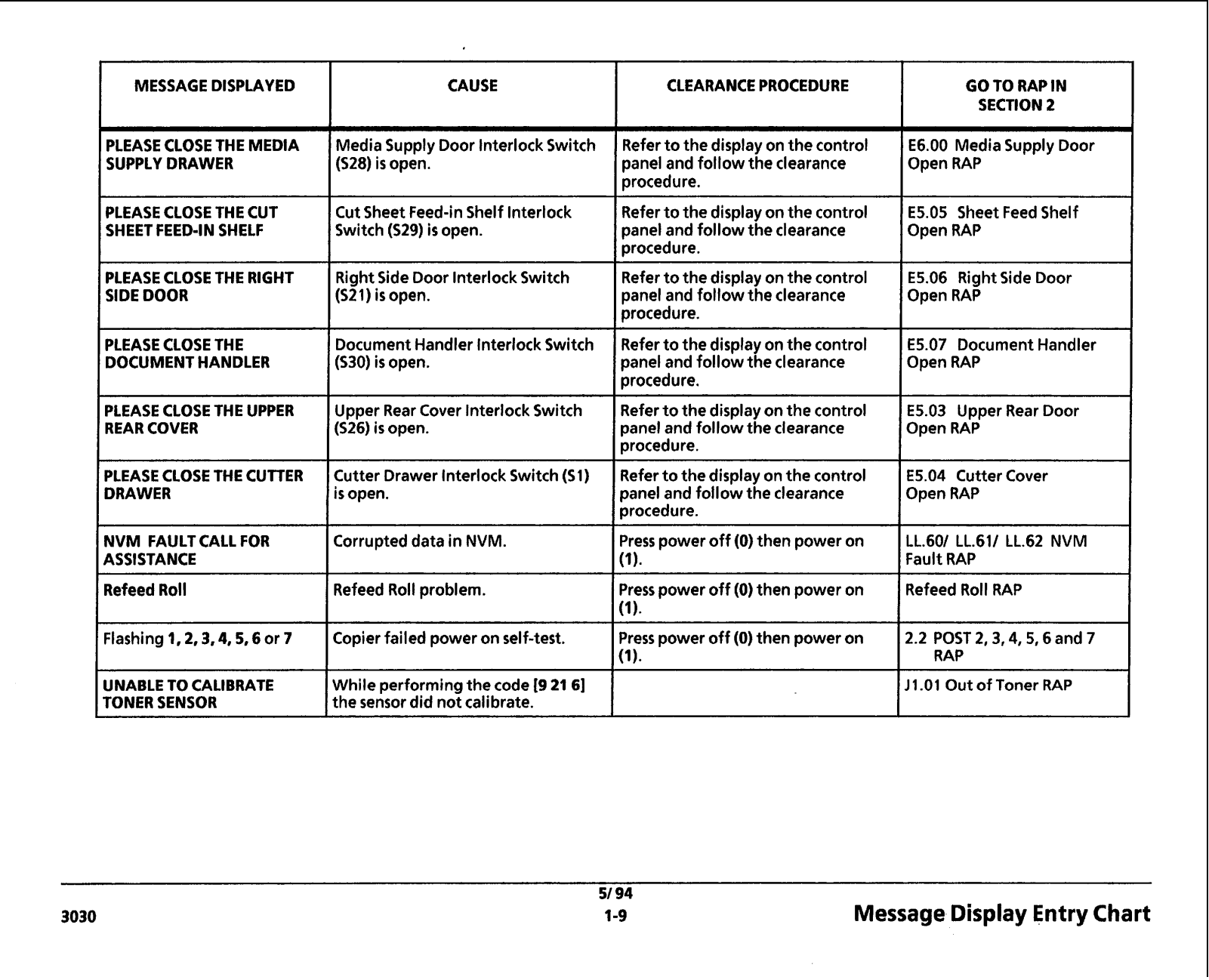
MESSAGE DISPLAYED

CAUSE

CLEARANCE PROCEDURE

GO TO RAP IN

I


SECTION 2


PLEASECLOSE THE MEDIA

MediaSupply Door lnterlock Switch

Refer to the display on the control

E6.00 MediaSupply Door


SUPPLY DRAWER

(S28) is open.

panel and follow the clearance

Open RAP


procedure.


PLEASECLOSE THE CUT

Cut Sheet Feed-inShelf lnterlock

Refer to the display onthe control

E5.05 Sheet FeedShelf


SHEET FEED-IN SHELF

Switch (529) is open.

panel and follow the clearance

Open RAP


procedure.


PLEASECLOSE THE RIGHT

Right Side Door InterlockSwitch

Refer to the display on the control

E5.06 Right Side Door


SIDE DOOR

(S21) is open.

panel and follow the clearance

Open RAP


procedure.


PLEASECLOSE THE

DocumentHandler InterlockSwitch

Referto the display on the control

E5.07 Document Handler


DOCUMENT HANDLER

(530) is open.

panel and follow the clearance

Open RAP


procedure.


PLEASECLOSE THE UPPER

Upper Rear Cover InterlockSwitch

Refer to the display onthe control

E5.03 Upper Rear Door


REAR COVER

(526) is open.

panel and follow the clearance

Open RAP


procedure.


PLEASECLOSE THE CUTTER

Cutter Drawer Interlock Switch (S1)

Refer to the display on the control

E5.04 Cutter Cover


DRAWER

i s open.

panel and follow the clearance

Open RAP


ICorrupteddata in NVM.

procedure.


NVM FAULT CALL FOR

Presspower off (0) then power on

LL.601 LL.611 LL.62 NVM


ASSISTANCE

IRefeedRoll problem.


Fault RAP


Refeed Roll

Presspower off (0)then power on


Flashing 1,2,3,4,5,6 or 7

ICopier failed power on self-test.

UNABLE TO CALIBRATE

I

While performingthe code 19 21 61

TONER SENSOR

the sensor did not calibrate.

3030

Press power off (0) then power on

2.2 POST 2,3,4,5,6

and 7

I

I

RAP


11-01Out of Toner RAP

I


51 94

Message Display Entry Chart

1-9

Maintenance Procedures

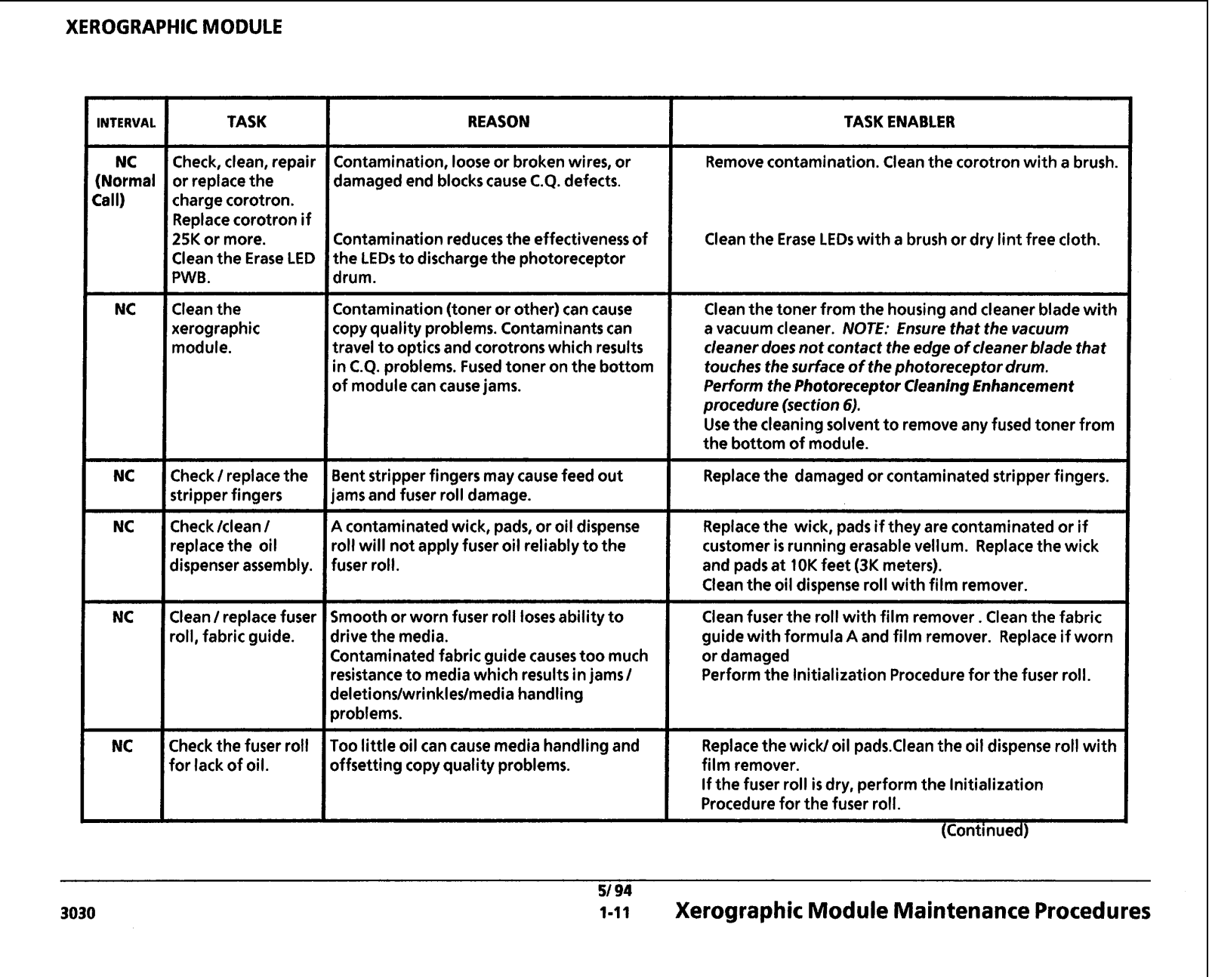
Performthe Tasks at the Intervalindicatedinthe tables. PerformNC (NormalCall) tasks on every call. The task with specific intervalsshould bedone only at the interval indicated.

DOCUMENT HANDLER

INTERVAL

TASK

REASON

NC

Cleanthe platen.

Spots on platencause lineson copy. Dustand

[Normal


other contaminantslower lighttransmission.

Calq


TASK ENABLER

Clean bothsidesof platenwith antistatic cleaner on a white cloth.

Cleanthe lower documentfeed rolls and optics cavity

Dirty feed rollscan causethe original to slip. Contaminantsin optics can cause C.Q. defects.

-- -- ---- - -- --

Cleanthe rolls and cavity usingthe FormulaA on atowel or cloth.

Cleanthe exposure

Contaminationon lampand lens result in

Apply asmall amount of antistatic cleaner to atowel.

lamp and lens.

copy quality defects.


Clean Upper

CQ problems.

Clean platenwith FormulaA on a white cloth.

Document Handler,


Top Platen, Top


Platen Idler Rolls.


Cleanthe

Documenthandlingproblems.

Cleanthe sensorswith FormulaA on awhite cloth.

Document Front


and RearSensors


Cleanthe Static

Documenthandlingproblems. Static on the

Cleanwith film remover or replace if damaged.

EliminatorBrushes

document


(Continued)

Document Handler MaintenanceProcedures

XEROGRAPHIC MODULE

INTERVAL

TASK

REASON

NC

Check, clean, repair

Contamination, looseor broken wires, or

(Normal

or replacethe

damaged end blockscause C.Q. defects.

Ca lI)

charge corotron.


Replacecorotron if

Contamination reducesthe effectivenessof


25K or more.


Cleanthe Erase LED

the LEDsto discharge the photoreceptor


PWB.

drum.


Cleanthe

Contamination(toner or other) can cause


xerographic

copy quality problems. Contaminantscan


module.

travel to opticsand corotronswhich results


in C.Q. problems. Fusedtoner on the bottom


of modulecan causejams.

Check/ replacethe

Bent stripper fingers may causefeed out

stripper fingers

ams and fuser roll damage.

Check /clean /

4 contaminatedwick, pads, or oil dispense

replacethe oil

*oil will not apply fuser oil reliably to the

dispenser assembly.

fuser roll.

Clean/ replacefuser

imooth or worn fuser roll losesability to

roll, fabric guide.

jrive the media.


Zontaminatedfabric guide causestoo much


.esistanceto media which resultsinjams/


jeletions/wrinkles/media handling


~roblems.

Check the fuser roll

roo little oil can cause media handling and

for lack of oil.

~ffsettingcopy quality problems.


5194

3030

1-11

TASK ENABLER

Removecontamination.Cleanthe corotron with a brush.

Cleanthe Erase LEDs with a brush or dry lint free cloth.

Cleanthe toner from the housingand cleaner bladewith a vacuum cleaner. NOTE: Ensure that the vacuum cleanerdoes not contact the edge o f cleaner blade that touches the surface o f the photoreceptor drum. Perform the Photoreceptor CleaningEnhancement procedure(section 6).

Usethe cleaning solvent to remove any fused toner from the bottom of module.

Replacethe damaged or contaminatedstripper fingers.

Replacethe wick, pads if they are contaminatedor if customer is running erasablevellum. Replacethe wick and padsat 1OK feet (3K meters).

Cleanthe oil dispense roll with film remover.

Cleanfuser the roll with film remover. Cleanthe fabric guidewith formula A and film remover. Replace if worn or damaged

Performthe Initialization Procedurefor the fuser roll.

Replacethe wick1oil pads.Clean the oil dispense roll with film remover.

If the fuser roll is dry, perform the Initialization Procedurefor the fuser roll.

(Continued)

Xerographic Module MaintenanceProcedures

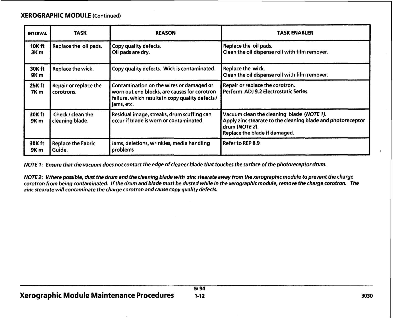
XEROGRAPHIC MODULE (Continued)

--

-


INTERVAL

TASK

REASON

TASK ENABLER

Replacethe oil pads.

Copy quality defects.

Replacethe oil pads.


Oil padsare dry.

Cleanthe oil dispense roll with film remover.

Replacethe wick.

Copyquality defects. Wick is contaminated.

Replacethe wick.


Cleanthe oil dispense roll with film remover.

Repair or replacethe

Contaminationon the wires or damagedor

Repair or replacethe corotron.

corotrons.

worn out end blocks, are causesfor corotron

Perform ADJ 9.2 Electrostatic Series.


failure, which resultsin copy quality defects1


jams, etc.


Check1cleanthe

Residualimage, streaks, drum scuffingcan

Vacuum cleanthe cleaning blade (NOTE 1).

cleaningblade.

occur if bladeis worn or contaminated.

Apply zinc stearate to the cleaningbladeand photoreceptor


drum (NOTE2).


Replacethe blade if damaged.

-

-


Replacethe ~ a b x

Jams, deletions, wrinkles, media handling

Referto REP 8.9

Guide.

problems


NOTE 1: Ensure that the vacuum does not contact the edge o f cleanerblade that touches the surface o f the photoreceptor drum.

NOTE2: Wherepossible, dust the drumandthe cleaningblade with zinc stearate away from the xerographicmodule to prevent the charge corotron from being contaminated. Ifthe drumandblademust bedustedwhile inthe xerographicmodule, removethe chargecorotron. The zinc stearate will contaminate the chargecorotron andcausecopy quality defects.

Xerographic Module MaintenanceProcedures

51 94

1-12 3030

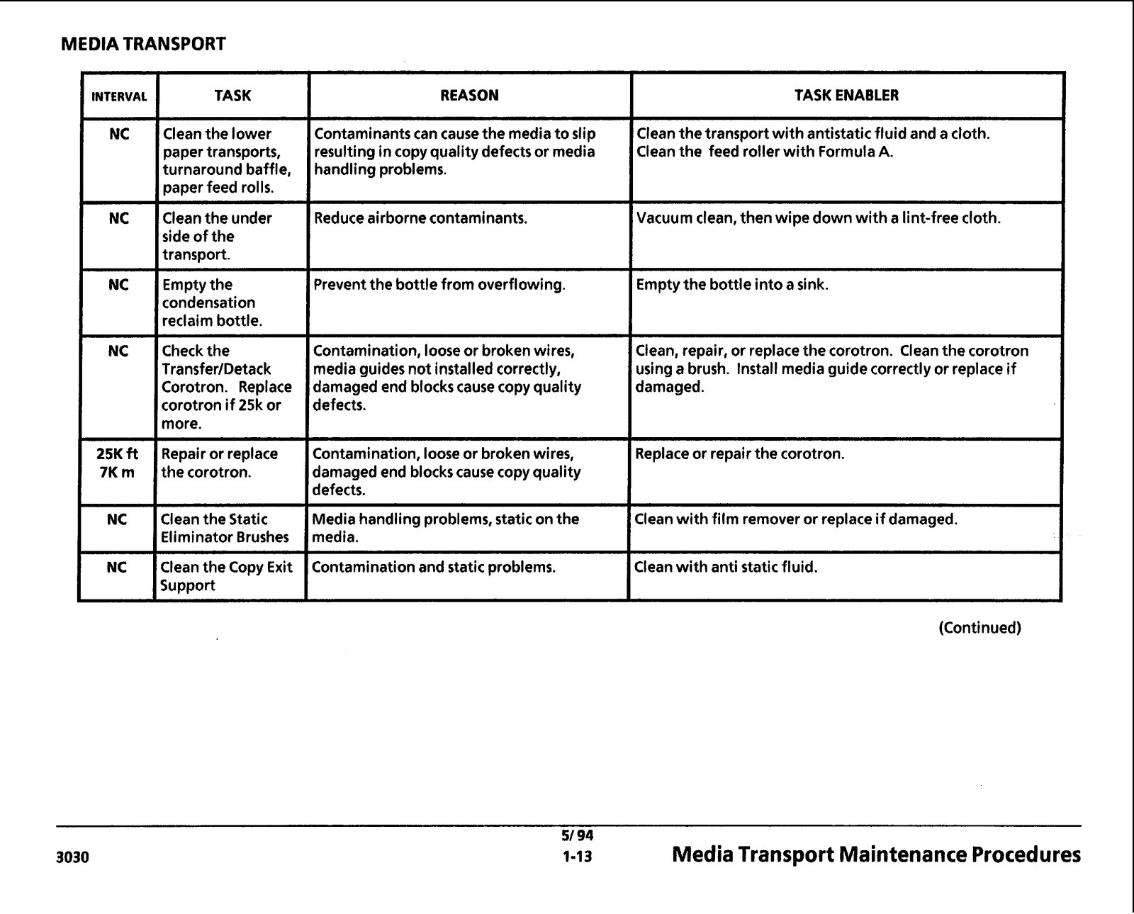
MEDIA TRANSPORT

INTERVAL

TASK


REASON


Cleanthe lower

Contaminantscan causethe mediato slip


paper transports,

resulting incopy qualitydefectsor media


turnaroundbaffle,

handlingproblems.


paper feed rolls.


Cleanthe under

Reduceairbornecontaminants.


side of the


transport.


-

-


Emptythe

Preventthe bottle from overflowing.


condensation


reclaim bottle.


Check the

Contamination, looseor brokenwires,


TransferIDetack

mediaguides not installedcorrectly,


Corotron. Replace

damaged end blockscausecopy quality


corotron if 25k or

defects.


more.


Repair or replace

Contamination, looseor brokenwires,


the corotron.

damaged end blockscause copy quality


defects.


Clean the Static

Media handlingproblems, static on the


Eliminator Brushes

media.


Cleanthe Copy Exit

Contaminationand static problems.


Support


51 94

TASK ENABLER

Cleanthe transport with antistatic fluid and a cloth. Cleanthe feed roller with FormulaA.

Vacuum clean, then wipe down with a lint-free cloth.

Emptythe bottle into a sink.

Clean, repair, or replace the corotron. Cleanthe corotron usinga brush. Install mediaguide correctly or replace if damaged.

Replaceor repairthe corotron.

Cleanwith film removeror replace if damaged.

Cleanwith anti static fluid.

(Continued)

1.1 3

Media Transport MaintenanceProcedures

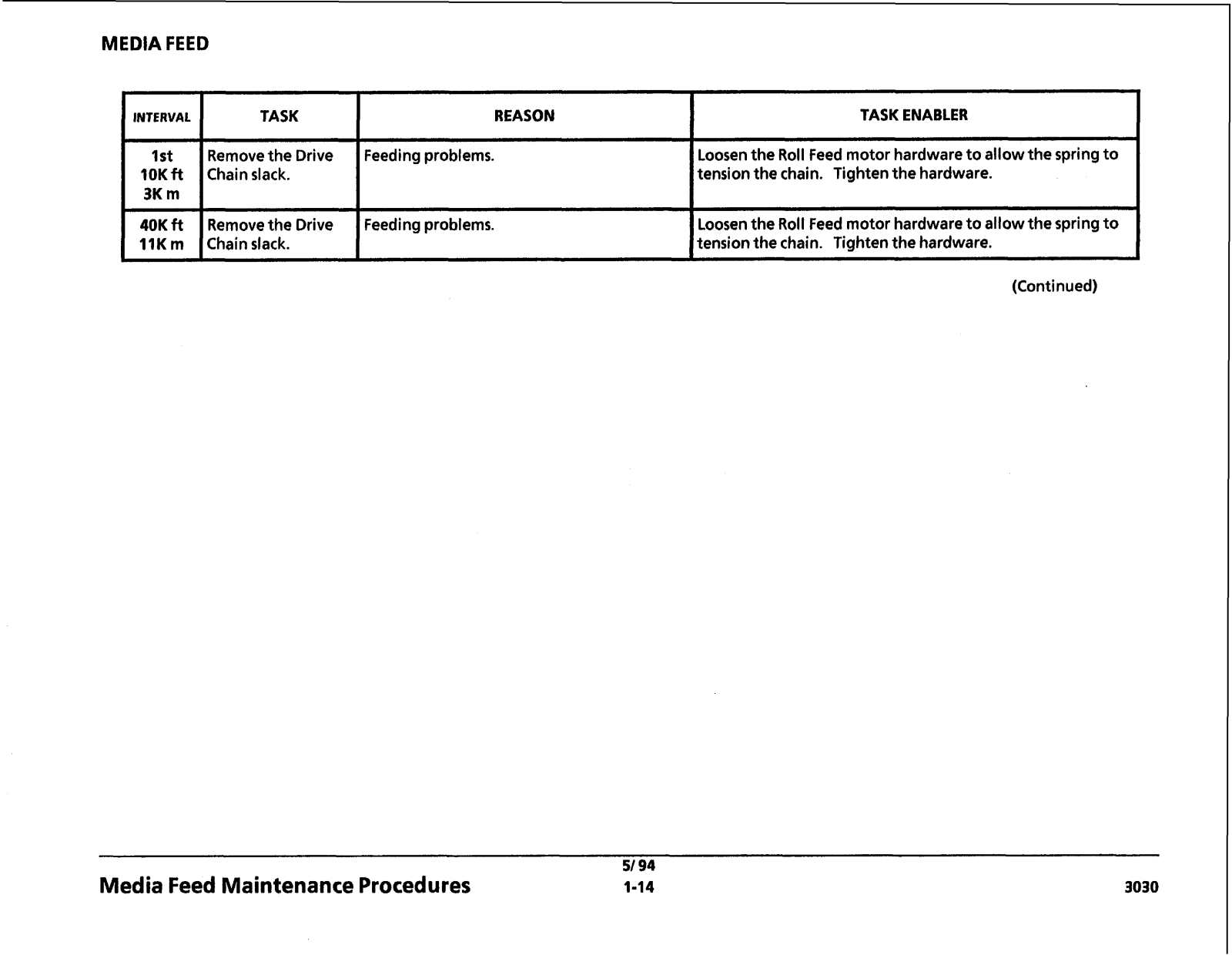
MEDIA FEED

INTERVAL

TASK

REASON

1st

Removethe Drive

Feeding problems.

10K ft

Chain slack.


3K m


40K ft

Removethe Drive

Feeding problems.

11K m

Chain slack.


TASK ENABLER

Loosenthe Roll Feed motor hardwareto allow the spring to tension the chain. Tightenthe hardware.

Loosenthe Roll Feed motor hardwareto allow the spring to tensionthe chain. Tightenthe hardware.

(Continued)

Media Feed Maintenance Procedures

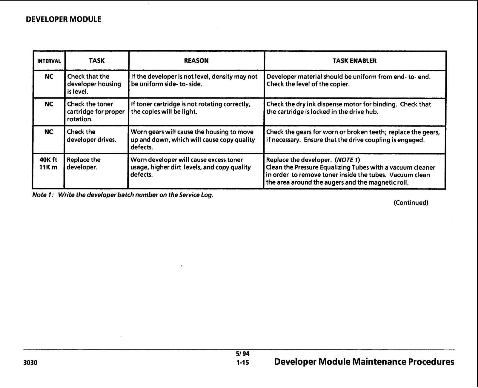
DEVELOPER MODULE

IINTERVAL I TASK


NC

I


Check that the


developer housing


is level.


NC

I


Check the toner


cartridge for proper

I


rotation.

NC

Checkthe


Ideveloper drives.


40K ft

Replacethe


11K m

developer.

REASON

If the developer is not level, density may not be uniform sideto- side.

If toner cartridgeis not rotatingcorrectly, the copies will be light.

Worn gearswill causethe housingto move up and down, which will cause copy quality defects.

Worn developer will cause excesstoner usage, higher dirt levels, and copy quality defects.

I

TASK ENABLER


IDevelopermaterial should be uniform from end-to- end. Checkthe level of the copier.

ICheck the dry ink dispense motor for binding. Check that the cartridge is locked inthe drive hub.

ICheck the gears for worn or brokenteeth; replacethe gears, if necessary. Ensurethat the drive coupling is engaged.

Replacethe developer. (NOTE 1)

Cleanthe Pressure EqualizingTubes with a vacuum cleaner inorder to removetoner insidethe tubes. Vacuum clean the area around the augersand the magnetic roll.

Note I: Write the developerbatch numberon the ServiceLog.

(Continued)


51 94

3030

1-15

Developer Module MaintenanceProcedures

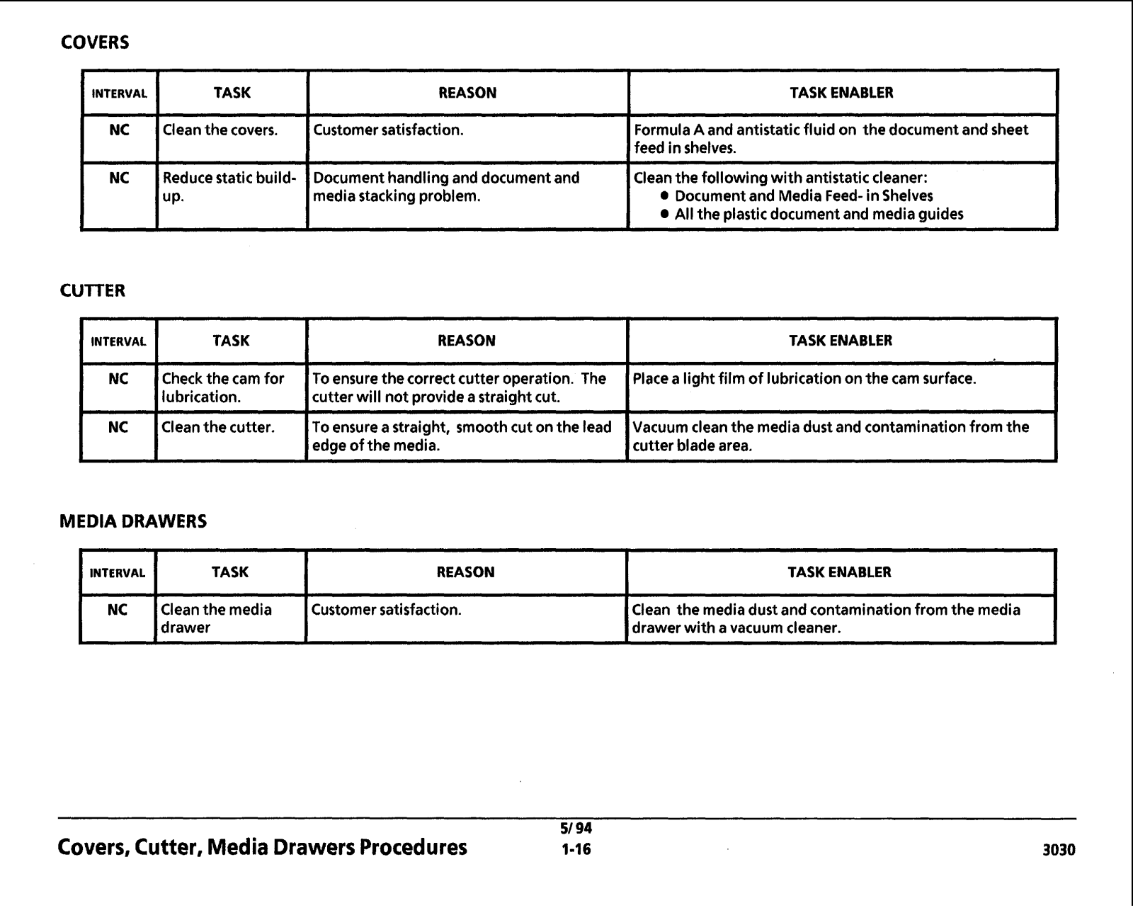
COVERS

INTERVAL

TASK

REASON

TASK ENABLER


Cleanthe covers.

Customer satisfaction.

FormulaA and antistatic fluid on the document and sheet


feed inshelves.

Reducestatic builduP.

CUTTER

1INTERVAL 1

TASK


NC


Check the cam for

I

1lubrication.

I

NC

Icleanthe cutter.

Document handlingand document and

Cleanthe following with antistatic cleaner:

mediastacking problem.

0 Documentand Media FeedinShelves


All the plastic document and media guides

REASON

TASK ENABLER

To ensure the correct cutter operation. The

Placea light film of lubricationonthe cam surface.

cutter will not providea straight cut.


To ensure a straight, smooth cut on the lead

Vacuum cleanthe mediadust and contamination from the

edge of the media.

cutter bladearea.

MEDIA DRAWERS

(

I

INTERVAL

I

TASK

I

REASON

I

TASK ENABLER

I

NC

ICleanthe media

ICustomer satisfaction.

(Clean the media dust and contamination from the media


1drawer


I


Idrawer with a vacuum cleaner.

I

Covers, Cutter, Media Drawers Procedures

51 94


1-16

3030

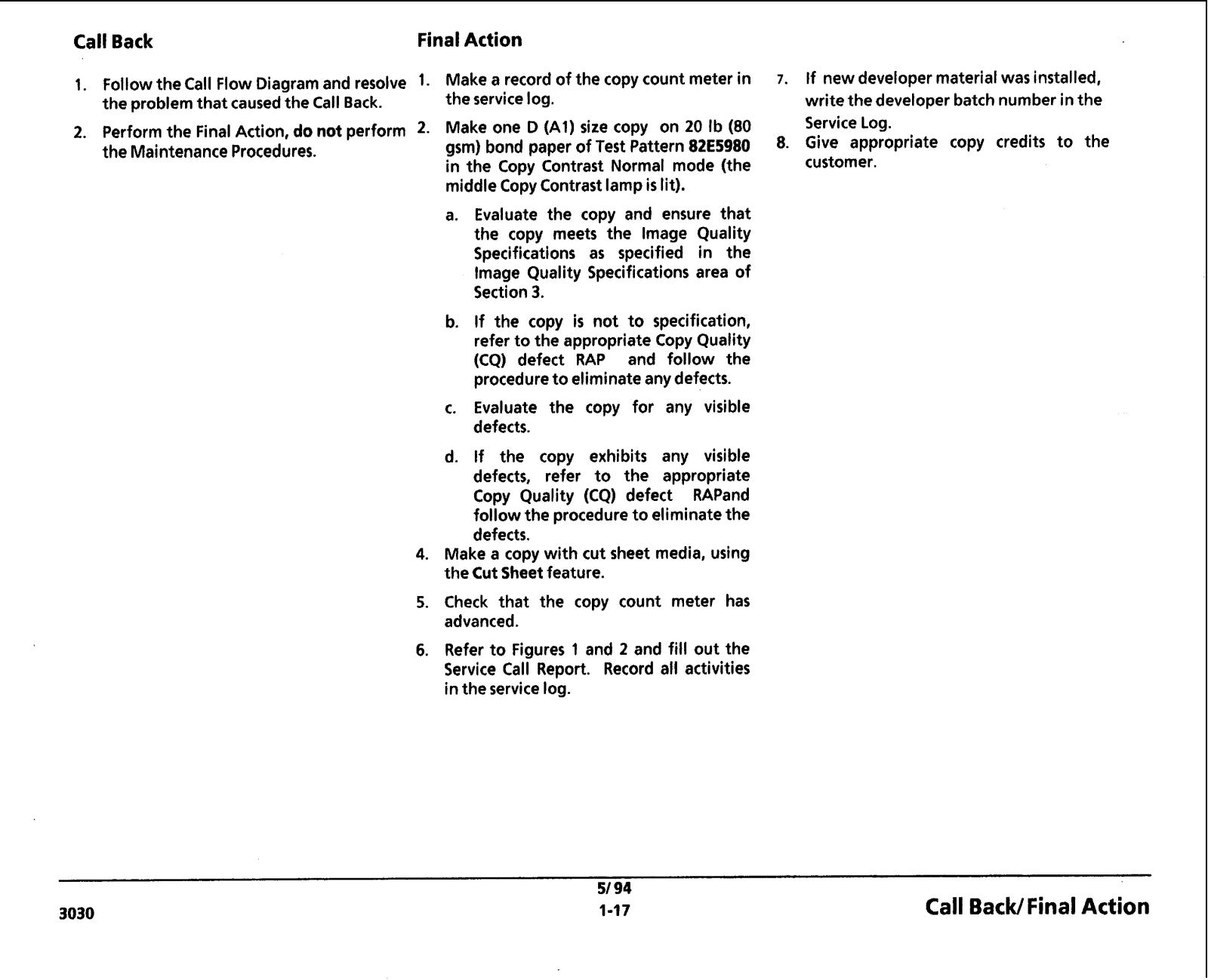
Call Back

Final Action


1.

Followthe Call Flow Diagram and resolve

1.

l V k k a record of the COPY count meter in


the problem that causedthe Call Back.


the service log.


2.

Perform the Final Action, do not perform

2-

Make one D (A11 size COPY

on 20 Ib (80


the Maintenance Procedures.


gsm) bond paper of Test Pattern82E5980


in the Copy Contrast Normal mode (the


middle Copy Contrast lamp is lit).


a. Evaluate the copy and ensure that


the copy meets the lmage Quality


Specifications as

specified

in the


lmage Quality Specifications area of


Section 3.


b. If the copy is not to specification,


refer to the appropriate Copy Quality


(CQ) defect RAP

and

follow the


procedureto eliminate any defects.


c. Evaluate the copy for any visible


defects.


d. If the copy exhibits any visible


defects,

refer to

the

appropriate


Copy Quality (CQ) defect

RAPand


follow the procedure to eliminate the


defects.


4. Make a copy with cut sheet media, using


the Cut Sheet feature.


5. Check that

the copy count meter has


advanced.


6. Refer to Figures 1 and 2 and fill out the Service Call Report. Record all activities inthe service log.

7.If new developer material was installed, write the developer batchnumber inthe Service Log.

8.Give appropriate copy credits to the customer.

51 94

3030

1-17

Call Back/ Final Action

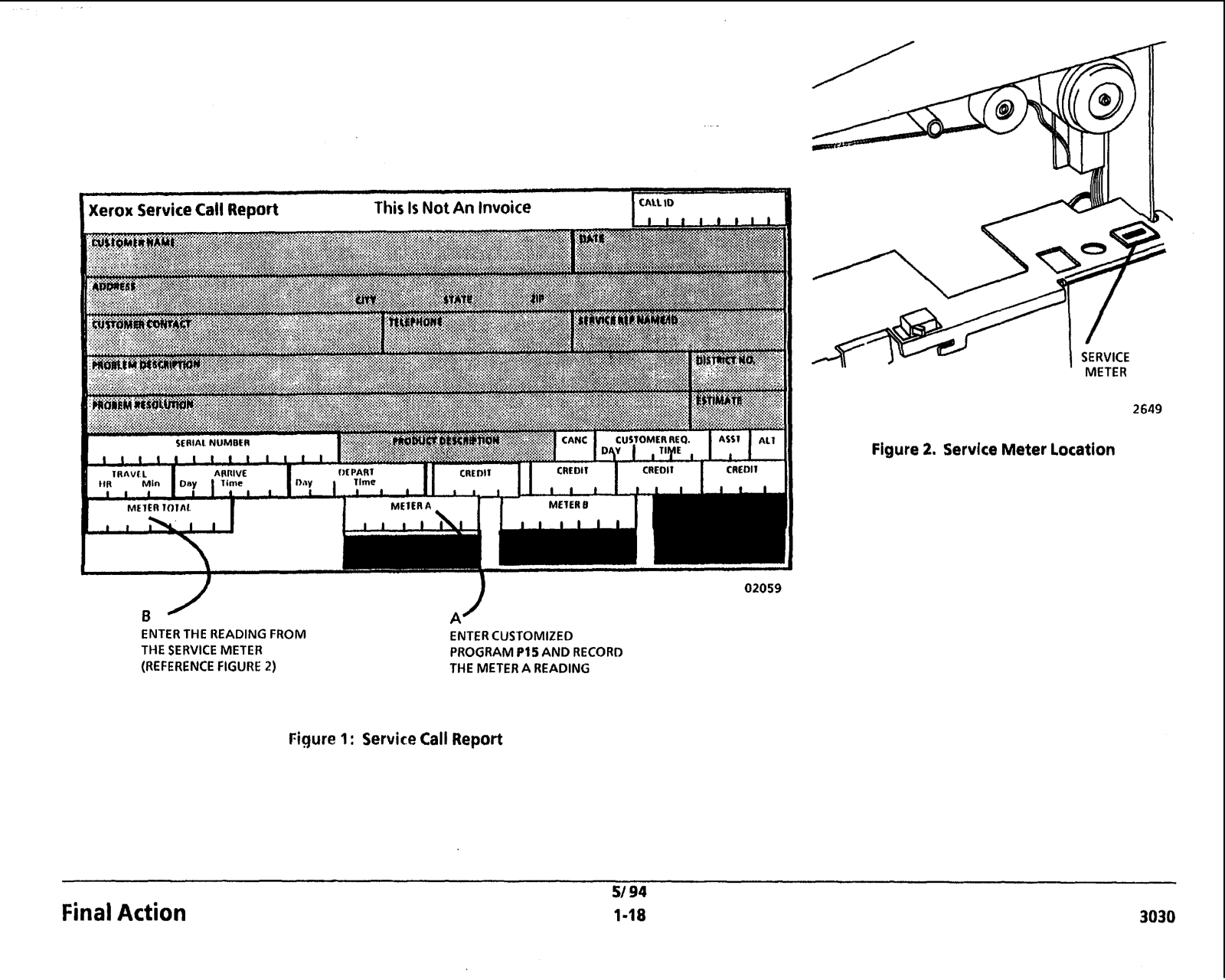
Xerox Service Call Report

Day

I

M E l E R l O l A L

ENTER THE READING FROM THE SERVICE METER (REFERENCE FIGURE 2)


. . . . . . I .

This Is Not An Invoice

C A U 10


I METER

2649

Figure 2. Service Meter Location

ENTER CUSTOMIZED

PROGRAMP I 5 AND RECORD

THE METER A READING

Figure 1: Service Call Report

Final Action

51 94


1-18

3030

Section Contents

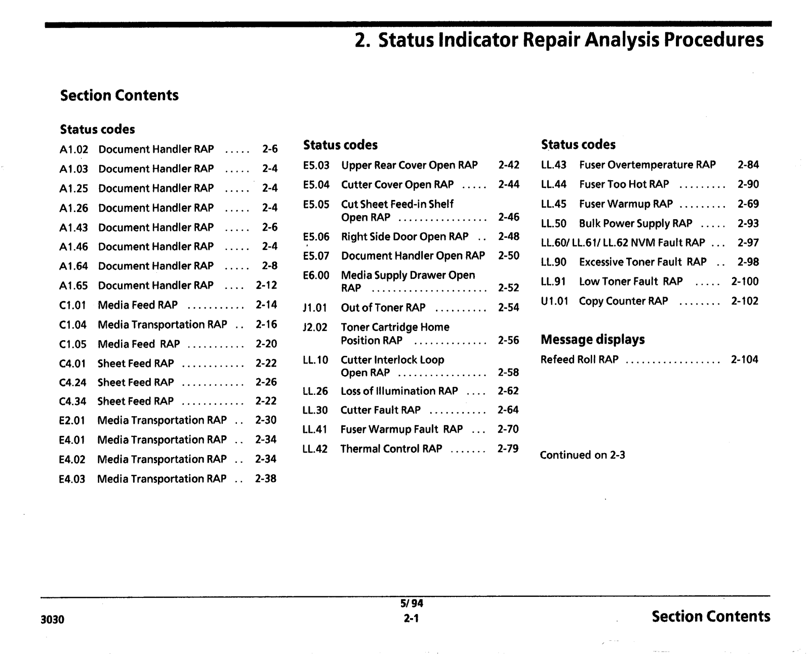
Status codes

A1.02

Document Handler RAP .....

2-6

A1.03

Document Handler RAP ... ..

2-4

A1.25

Document Handler RAP .....

2-4

A1.26

Document Handler RAP .....

2-4

A1.43

Document Handler RAP .....

2-6

A1A6

Document Handler RAP .....

2-4

Al.64

Document Handler RAP .....

2-8

Al.65

Document Handler RAP ....

2-12

C1.O1

Media Feed RAP ...........

2-14

C1.O4

Media Transportation RAP ..

2-16

C1.05

Media Feed RAP . ..... ... ..

2-20

C4.01

Sheet Feed RAP ............

2-22

C4.24

Sheet Feed RAP ............

2-26

C4.34

Sheet Feed RAP .... ........

2-22

E2.01

Media Transportation RAP ..

2-30

E4.01

Media Transportation RAP ..

2-34

E4.02

Media Transportation RAP ..

2-34

E4.03

Media Transportation RAP ..

2-38

3030

--- -- -- -

2. Status Indicator Repair Analysis Procedures

Status codes

E5.03 Upper Rear Cover Open RAP

E5.04

Cutter Cover Open RAP .....

E5.05 Cut Sheet Feed-inShelf


Open RAP .................

E5.06

Right Side Door Open RAP ..

E5.07 Document Handler Open RAP

E6.00 Media Supply Drawer Open


RAP ......................

J1.O1

OutofTonerRAP ..........

J2.02

Toner Cartridge Home


Position RAP .............

LL.10 Cutter Interlock Loop


Open RAP ...... ...........

LL.26

Loss of Illumination RAP ....

LL.30

Cutter Fault RAP ... ........

LL.41

FuserWarmup Fault RAP ...

LL.42

Thermal Control RAP . ......

Status codes

LL.43

Fuser Overtemperature RAP

2-84

LL.44

Fuser Too Hot RAP .... . ....

2-90

LL.45

FuserWarmup RAP .........

2-69

LL.50

Bulk Power Supply RAP .....

2-93

LL.601LL.611LL.62 NVM Fault RAP ...

2-97

LL.90

ExcessiveToner Fault RAP ..

2-98

LL.91

Low Toner Fault RAP .. ...

2-100

U1.O1

Copy Counter RAP ........

2-102

Message displays


Refeed Roll RAP ..................

2-104

Continued on 2-3

51 94

Section Contents

2-1

Notes:

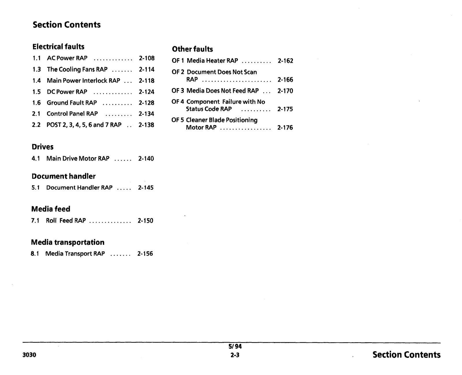
Section Contents

Electricalfaults

AC Power RAP .............

2-108

The Cooling Fans RAP .......

2-114

Main Power Interlock RAP ...

2-118

DC Power RAP .............

2-124

Ground Fault RAP ..........

2-128

Control Panel RAP .........

2-134

POST 2,3,4,5,6 and 7 RAP ..

2-138

Drives


4.1 Main Drive Motor RAP ......

2-140

Document handler

5.1Document Handler RAP ..... 2- I45

Media feed

7.1 Roll Feed RAP ..............

2- 150

Media transportation

8.1 Media Transport RAP .......

2- 156

3030

Other faults

OF 1 Media Heater RAP ..........

2-162

OF 2 Document Does Not Scan

2- 166

RAP .......................

OF 3 Media Does Not Feed RAP ...

2-170

OF 4 Component Failurewith No


Status Code RAP ..........

2-175

OF 5 Cleaner Blade Positioning

2-176

Motor RAP .................

51 94

Section Contents

2-3

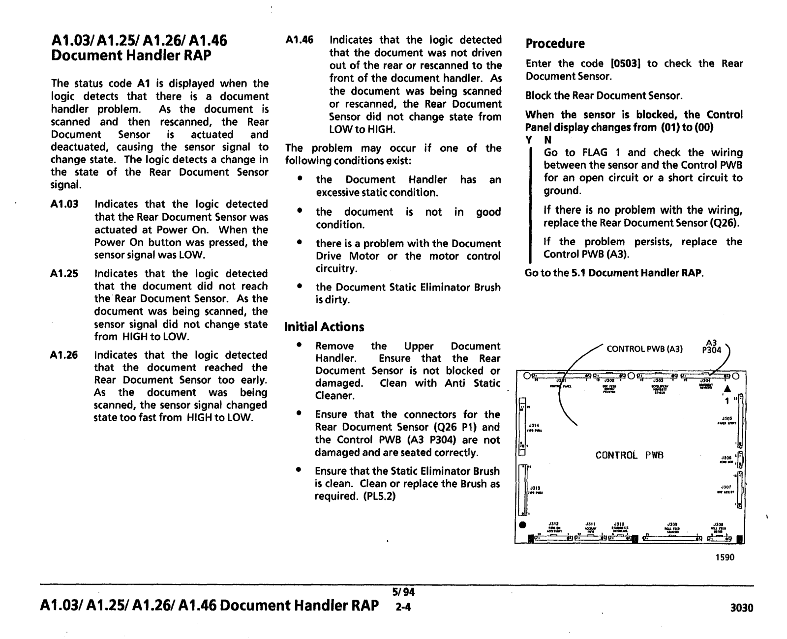
A1.03lA1 .2S/ Al.261 Al.46

Document Handler RAP

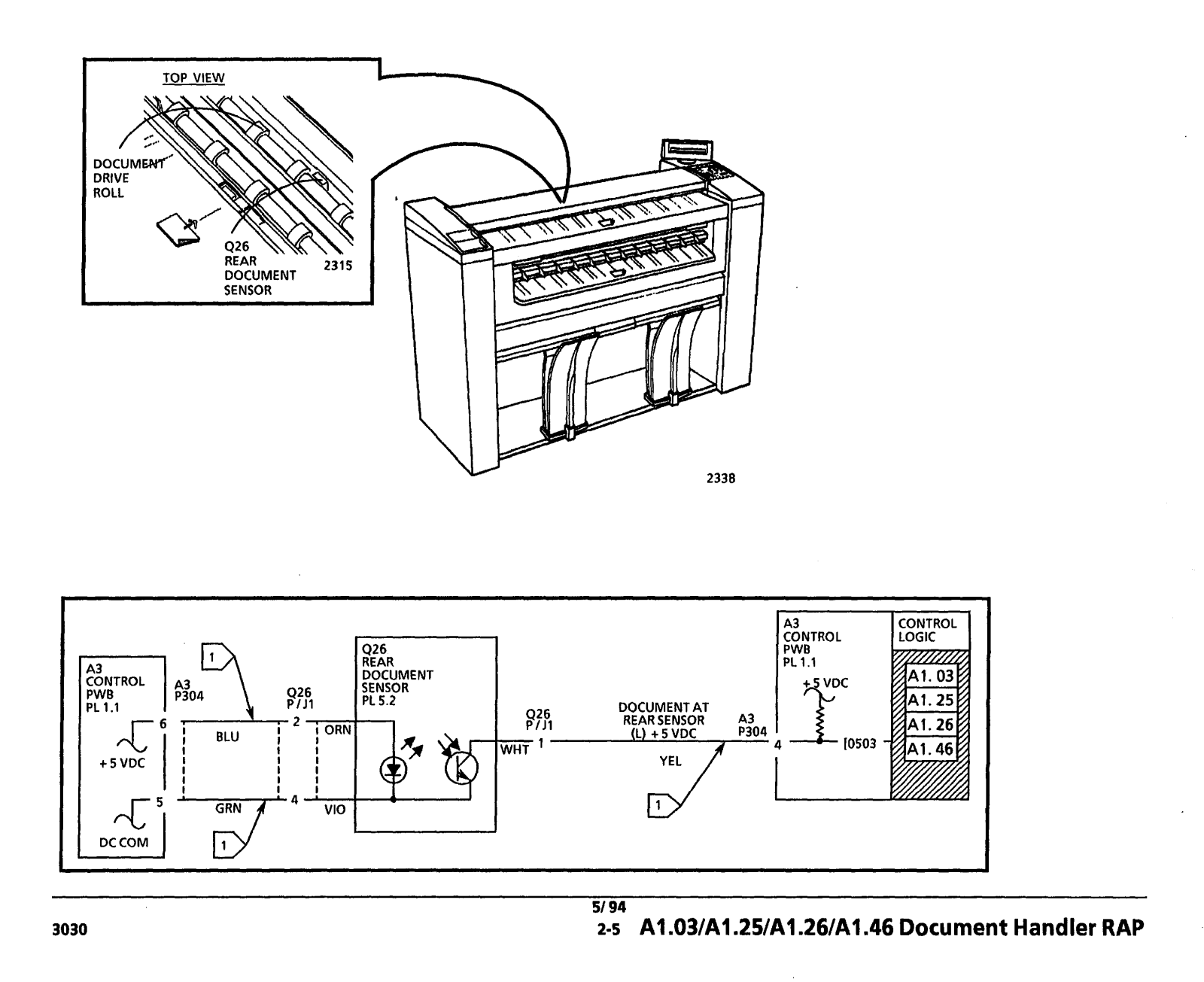
The status code A1 is displayed when the logic detects that there is a document handler problem. As the document is scanned and then rescanned, the Rear Document Sensor is actuated and deactuated, causing the sensor signal to change state. The logic detects a change in the state of the Rear Document Sensor signal.

A1.O3 lndicates that the logic detected that the Rear Document Sensor was actuated at Power On. When the Power On button was pressed, the sensor signal was LOW.

lndicates that the logic detected that the document did not reach the'Rear Document Sensor. As the document was being scanned, the sensor signal did not change state from HlGHto LOW.

lndicates that the logic detected that the document reached the Rear Document Sensor too early. As the document was being scanned, the sensor signal changed state too fast from HlGHto LOW.

A1.46 lndicates that the logic detected that the document was not driven out of the rear or rescanned to the front of the document handler. As the document was being scanned or rescanned, the Rear Document Sensor did not change state from LOW to HIGH.

The problem may occur if one of the following conditionsexist:

the Document Handler has an excessivestatic condition.

the document is not in good condition.

there is a problem with the Document Drive Motor or the motor control circuitry.

the Document Static Eliminator Brush

is dirty.

InitialActions

Remove the Upper Document Handler. Ensure that the Rear Document Sensor is not blocked or damaged. Clean with Anti Static Cleaner.

Ensure that the connectors for the Rear Document Sensor (426 P I ) and the Control PWB (A3 P304) are not damaged and are seated correctly.

Ensurethat the Static Eliminator Brush is clean. Clean or replace the Brush as required. (PL5.2)

5194

A1.03/ A1.25/ A1.261 A1.46 Document Handler RAP 2-4

Procedure

Enter the code [0503] to check the Rear DocumentSensor.

Block the Rear DocumentSensor.

When the sensor is blocked, the Control Paneldisplay changesfrom (01) to (00)

YN

Go to FLAG 1 and check the wiring betweenthe sensor and the Control PWB for an open circuit or a short circuit to ground.

If there is no problem with the wiring, replacethe Rear DocumentSensor (Q26).

If the problem persists, replace the Control PWB (A3).

Go to the 5.1 Document Handler RAP.


/ CONTROL PWB (A31

P%4)


/


S ? "

;=/y

0


ylq-

0P


=&

"-

ST

,A


mun,,".w


1 **fl

IF..

\


,,,


H,


CONTROL

PWB


3030

CONTROL

PL 1.1

t 5 VDC

I

I I

7-4-

I VIO

PI


DC COM


IA3

1 CONTROL

I


1 LOGIC

I

9 2 6

REAR DOCUMENT SENSOR

PL 5.2


51 94

3030

2-5 A1.03lAI .25/A1.26/AI .46 Document Handler RAP

A1.021A1.43 Document

Handler RAP

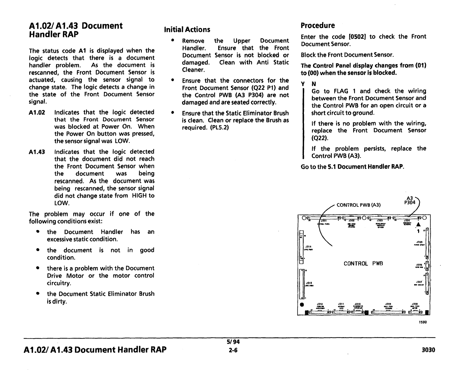
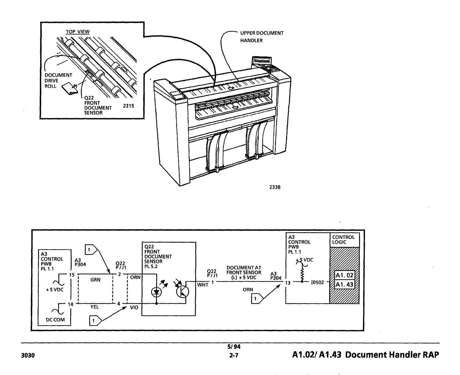
The status code A1 is displayed when the logic detects that there is a document handler problem. As the document is rescanned, the Front Document Sensor is actuated, causing the sensor signal to change state. The logic detects a change in the state of the Front Document Sensor signal.

Indicates that the logic detected that the Front Document Sensor was blocked at Power On. When the Power On button was pressed, the sensor signal was LOW.

Indicates that the logic detected that the document did not reach the Front Document Sensor when the document was being rescanned. As the document was being rescanned, the sensor signal did not change state from HIGH to LOW.

The problem may occur if one of the following conditionsexist:

the Document Handler has an excessive static condition.

the document is not in good condition.

there is a problem with the Document Drive Motor or the motor control circuitry.

the Document Static Eliminator Brush

is dirty.

Initial Actions

Remove the Upper Document Handler. Ensure that the Front Document Sensor is not blocked or damaged. Clean with Anti Static Cleaner.

Ensure that the connectors for the Front Document Sensor (422 PI) and the Control PWB (A3 P304) are not damaged and are seated correctly.

Ensurethat the Static Eliminator Brush is clean. Clean or replace the Brush as required. (PL5.2)

A1.02/ A1.43 Document Handler RAP

51 94

2-6

Procedure

Enter the code [0502] to check the Front DocumentSensor.

Block the Front DocumentSensor.

The Control Panel display changes from (01) to (00) when the sensor is blocked.

YN

Go to FLAG 1 and check the wiring betweenthe Front Document Sensor and the Control PWB for an open circuit or a short circuit to ground.

If there is no problem with the wiring, replace the Front Document Sensor

(422).

If the problem persists, replace the Control PWB (A3).

Go to the 5.1 Document HandlerRAP.

/ CONTROL PWB (A3)

CONTROL PWB

3030

TOP VIEW

FRONT

I

DOCUMENT 2315


SENSOR


A3 CONTROL PWB

PL 1.1

L-

+5 VDC

UPPER DOCUMENT

HANDLER

A3

CONTROL

PWB

PL1.l

DOCUMENT AT


FRONTSENSOR

~3

(L) +5 VDC

P304

A1.021 A1.43 Document Handler RAP

A1.64 Document Handler RAP

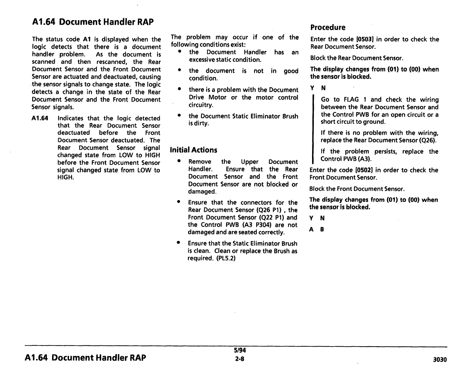
The status code A1 is displayed when the logic detects that there is a document handler problem. As the document is scanned and then rescanned, the Rear Document Sensor and the Front Document Sensor are actuated and deactuated, causing the sensor signals to change state. The logic detects a change in the state of the Rear Document Sensor and the Front Document Sensor signals.

A1.64 Indicates that the logic detected that the Rear Document Sensor deactuated before the Front Document Sensor deactuated. The Rear Document Sensor signal changed state from LOW to HIGH before the Front Document Sensor signal changed state from LOW to HIGH.

The problem may occur if one of the following conditionsexist:

the Document Handler has an excessive static condition.

the document is not in good condition.

there is a problem with the Document Drive Motor or the motor control circuitry.

the Document Static Eliminator Brush

is dirty.

Initial Actions

Remove the Upper Document Handler. Ensure that the Rear Document Sensor and the Front Document Sensor are not blocked or damaged.

Ensure that the connectors for the Rear Document Sensor (426 PA) ,the Front Document Sensor (Q22 PI) and the Control PWB (A3 P304) are not damagedand are seated correctly.

Ensure that the Static Eliminator Brush is clean. Clean or replacethe Brush as required. (PL5.2)

5/94

Procedure

Enter the code I05031 in order to check the Rear Document Sensor.

Blockthe Rear Document Sensor.

The display changes from (01) to (00) when the sensor is blocked.

Go to FLAG 1 and check the wiring between the Rear Document Sensor and the Control PWB for an open circuit or a short circuit to ground.

If there is no problem with the wiring, replacethe Rear Document Sensor (426).

If the problem persists, replace the Control PWB(A3).

Enter the code [0502] in order to check the Front Document Sensor.

Block the Front Document Sensor.

The display changes from (01) to (00) when the sensor is blocked.

A1.64 Document Handler RAP

2-8

3030

Loading...
+ 502 hidden pages