

Page 1
XS400 Sine Wave Inverter
Owner’s Guide
Page 2

Page 3

XS400 Sine Wave Inverter
Owner’s Guide
Page 4

About Xantrex
Xantrex Technology Inc. is a world-leading supplier of advanced power electronics and controls with products from
50 watt mobile units to one MW utility-scale systems for wind, solar, batteries, fuel cel ls, microturbin es , and backup
power applications in both grid-connected and stand-alone syst ems. Xantrex products inc lude inverters, battery
chargers, programmable power supplies, and variabl e s peed drives that conve rt, supply, control, clean, and distribut e
electri cal power.
Trademarks
XS400 Sine Wave Inverter is a trademark of Xantrex International. Xantrex is a registered trademark of Xantrex
International.
Other trademarks, registered trademarks, and product names are the property of their respective owners and are used
herein for identi fication purposes onl y.
Notice of Copyright
XS400 Sine Wave Inverter Owner’s Guide © October 2003 Xantrex International. All rights reserved.
Disclaimer
UNLESS SPECIFICALLY AGREED TO IN WRITING, XANTREX TECHNOLOGY INC. (“XANTREX”)
(a) MAKES NO WARRANTY AS TO THE ACCURACY, SUFFICIENCY OR SUITABILITY OF ANY
TECHNICAL OR OTHER INFORMAT ION PROVIDED IN ITS MANUALS OR OTHER DOCUMENTATION.
(b) ASSUMES NO RESPONSIBILITY OR LIABILITY FOR LOSS OR DAMAGE, WHETHER DIRECT,
INDIRECT, CONSEQUENTIAL OR INCIDENTAL, WHICH MIGHT ARISE OUT OF THE USE OF SUCH
INFORMATION. THE USE OF ANY SUCH INFORMATION WILL BE ENTIRELY AT THE USER’S RISK.
Date and Revision
October 2003 Revision B
Part Number
975-0054-01-01
Contact Inform at ion
Telephone: 1-800-670-0707 (toll free in North America)
1-604-422-2777 (direct)
Fax: 1-604-420-2145
Email: CustomerService@xantrex.com
Web: www.xantrex.com
Page 5

About This G uide
Purpose
The XS400 Sine Wave Inverter Owner’s Guide contains information for
installing, operating, and troubleshooting the XS400 Sine Wa ve Inverter
(XS400) and the S400 Remote Switch.
Scope
This Guide provides safety guide lines, installation, operation,
troubleshooti ng, a nd warranty information for the XS400 and S400
Remote Switch.
Basic information on battery types and sizes is provided in Appendix B,
“Battery Types and Sizes”. For comprehensive information about your
battery, refer to the battery manufacturer’s guide.
Service information is not inc luded as the unit does not contain user serviceable parts.
Audience
This Guide is intended for anyone who needs to install and operate the
XS400 Sine Wave Inverter and S400 Remote Switch. Installer s should be
certified technicians or electricians.
Organization
The Owner’s Guide is or ganized into four chapters and two appendixes.
Chapter 1, “Introduction”, outlines the main performance and safety
features of the XS400. Reading this chapter will give you a clear
understanding of the inverter’s capabilities.
Chapter 2, “Installation”, provides detailed information for install ing the
XS400 and the S400 Remote Switch.
975-0054-01-01 iii
Page 6
About This Guide
Chapter 3, “Operation”, provides information about operating the XS400
and S400 Remote Switch. Details are provide d on how to read the front
panel indicators to monit or the XS400.
Chapter 4, “Troubleshooting”, explains how to identify and solve
problems that can occur with the XS400 and S400 Remote Switch.
Appendix A, “Specifications”, provides the electrical and physical
specifications of the XS400.
Appendix B, “Battery Types and Sizes”, provides information that will
help you to select, connect, and maint ain batteries that are most
appropriate for your application.
“Warranty and Product Information”, contains the product warranty,
explains how to ret urn a product f or se rvice, and describe s how to prepa re
for a call to Xantrex Customer Service.
Conv en t io n s Used
The following conventions are used in this guide.
WARNING
W arnings identify condit ions that could result in personal
injury or loss of life.
CAUTION
Cautions identify conditio ns or practi ces that could resul t in
damage to the XS400 Sine Wave Inverter or to other
equipment.
Note: Notes describe addit ional information which may add to
your understanding of how to use the XS400.
Important:
item that you must pay attention to.
These notes describe an important action item or an
iv 975-0054-01-01
Page 7

Acronyms and Terminology
AC Alternating current
DC Direct current
CSA Canadian Standards Asso ciation
FCC Federal Communications Commission
GFCI Ground fault circuit interrupter
UL Underwriters Laboratories Inc.
Hardwiring to make a permanent electrical connection
Shore power refers to the AC input power from a utility grid,
generator, or other external AC source.
Relat ed Inf o rmation
You can find more information about Xantrex Technology Inc. as well as
its products and servic es at www.xantrex.com
About This Guide
975-0054-01-01 v
Page 8

vi
Page 9
Important Safety Instructions
WARNING
This Owner’s Guide contain s important safety and operating
instructions.
Before using your XS400 Sine Wave Inverter, be sure to read,
understand, and sa ve these safety instructions.
WARNING: Restrictions on Use
The XS400 Sine W ave Inverter shall not be used in connection
with life support systems or other medical eq uipment or
devices.
WARNING: Shock hazard
The XS400 has On/St andby mode only. It does not have an Off
mode, that is, DC power is permanently connected to the unit.
General Precautions
1. Before installing and using the inverter, read all appropriate sections
of this guide and any cautionary marking s on the inverter and the
batteries.
2. Do not operate the inverter if it has received a sharp blow, been
dropped, or oth erwise da maged. If the unit is da maged, see “Warranty
and Product Information” on page WA–1.
3. Do not dismantle the inverter ; it contains no user serviceable parts.
Attempting to s ervice the uni t yourself coul d cause e lectr ical shock or
fire. Internal capacitors remain charged after all power is
disconnected. See “Warranty” on page W A– 1 for instructions on
obtaining servic e.
975-0054-01-01 vii
Page 10
Important Safety Instructions
4. T o reduce the risk of electric al shock, disconnect both AC and DC
power from the inverter before working on any circuits connected to
the inverter. Turning the On/Standby swit ch to Standby ( ) will not
reduce this risk.
5. Protect the inverte r from rain, snow, spray, and water.
6. T o reduc e the risk of overheating, keep the ven tilati on openings c lear ,
and do not install the inverter in a compartment with limited airflow.
Precautions When Working With Batteries
WARNIN G: Explosion and Fire Hazard
1. To reduce the risk of battery explosion, follow all instructions
published by the battery manuf actur er and the manufacturer of the
equipment in which the battery is installed.
2. Make sure the area around the battery is well ventilated.
3. Never smoke or allow a spark or flame near the engine or batteries.
4. Use caution to r educe the risk of drop ping a metal tool on the bat tery.
It could spark or short circuit the bat tery or other electrical parts and
could cause an explosion.
Explosiv e Gas Precautio ns
1. Batteries generate expl osive gases during normal operation. Be sure
you follow all relevant ins tructions exactly before installing or using
your inverter.
2. This equipment contains components which tend to produce arcs or
sparks. To prevent fire or explosion, do not install the inverter in
compartments containing batteries or flammable materials or in
locations that requi re ig nition-p rotected e quip ment. This i nclude s any
space containing gasoline-powered machinery, fuel tanks, as well as
joints, fittings, or other connections between components of the fuel
system.
viii 975-0054-01-01
Page 11

FCC Information to the User
This Class B device complies with Part 15 of the FCC Rules and all
requirements of the Canadian Interference-Causing Equipm ent
Regulations. Operation is subj ect to the following two conditio ns: (1) this
device may not cause harmful interference, and (2) this device must
accept any interference received, including interf erence that may cause
undesired operati on.
Important Safety Instructions
975-0054-01-01 ix
Page 12

x
Page 13

Contents
Important Safety Instructions
General Precautions - - - - - - - - - - - - - - - - - - - - - - - - - - - - - - - - - - - - - - - - - - - - - - - - vii
Precautions When Working With Batteries - - - - - - - - - - - - - - - - - - - - - - - - - - - - - - - - viii
Explosive Gas Precautions - - - - - - - - - - - - - - - - - - - - - - - - - - - - - - - - - - - - - - - - - - - viii
FCC Information to the User - - - - - - - - - - - - - - - - - - - - - - - - - - - - - - - - - - - - - - - - - - - ix
1
Introduction
How XS400 Works - - - - - - - - - - - - - - - - - - - - - - - - - - - - - - - - - - - - - - - - - - - - - - - -1–2
Premium Power and Ease of Use- - - - - - - - - - - - - - - - - - - - - - - - - - - - - - - - - - - - - - -1–2
Comprehensive Protection - - - - - - - - - - - - - - - - - - - - - - - - - - - - - - - - - - - - - - - - - - -1–3
XS400 Features - - - - - - - - - - - - - - - - - - - - - - - - - - - - - - - - - - - - - - - - - - - - - - - - - -1–4
Front Panel - - - - - - - - - - - - - - - - - - - - - - - - - - - - - - - - - - - - - - - - - - - - - - - - - - -1–4
Back Panel - - - - - - - - - - - - - - - - - - - - - - - - - - - - - - - - - - - - - - - - - - - - - - - - - - -1–5
S400 Remote Switch - - - - - - - - - - - - - - - - - - - - - - - - - - - - - - - - - - - - - - - - - - - - - - -1–6
Front Panel - - - - - - - - - - - - - - - - - - - - - - - - - - - - - - - - - - - - - - - - - - - - - - - - - - -1–6
Back Panel - - - - - - - - - - - - - - - - - - - - - - - - - - - - - - - - - - - - - - - - - - - - - - - - - - -1–6
2
Installation
Introduction - - - - - - - - - - - - - - - - - - - - - - - - - - - - - - - - - - - - - - - - - - - - - - - - - - - - -2–2
Preparing for Installa tion - - - - - - - - - - - - - - - - - - - - - - - - - - - - - - - - - - - - - - - - - - - -2–3
Installation Codes - - - - - - - - - - - - - - - - - - - - - - - - - - - - - - - - - - - - - - - - - - - - - -2–3
Materials List - - - - - - - - - - - - - - - - - - - - - - - - - - - - - - - - - - - - - - - - - - - - - - - - -2–4
Installation Tools a nd Materials - - - - - - - - - - - - - - - - - - - - - - - - - - - - - - - - - - - - -2–4
Installing the XS400 - - - - - - - - - - - - - - - - - - - - - - - - - - - - - - - - - - - - - - - - - - - - - - -2–6
Overview - - - - - - - - - - - - - - - - - - - - - - - - - - - - - - - - - - - - - - - - - - - - - - - - - - - -2–6
Step 1: Designing Your Install ation - - - - - - - - - - - - - - - - - - - - - - - - - - - - - - - - - -2–6
Step 2: Mounting Your Inverter - - - - - - - - - - - - - - - - - - - - - - - - - - - - - - - - - - - -2–10
Step 3: Connecting the Chassis Ground - - - - - - - - - - - - - - - - - - - - - - - - - - - - - - -2–11
Step 4: Installing the S400 Remote Switch - - - - - - - - - - - - - - - - - - - - - - - - - - - - -2–12
Step 5: Getting Ready to Connect the DC Cables - - - - - - - - - - - - - - - - - - - - - - - -2–14
Step 6: Routing the DC Cables - - - - - - - - - - - - - - - - - - - - - - - - - - - - - - - - - - - -2–15
Step 7: Connecting the DC Cables - - - - - - - - - - - - - - - - - - - - - - - - - - - - - - - - - -2–16
Step 8: Connecting Your Appliances to the GFCI Outlets - - - - - - - - - - - - - - - - - -2–18
Step 9: Hardwiring the AC Output - - - - - - - - - - - - - - - - - - - - - - - - - - - - - - - - - -2–19
Step 10: Performing Checks Prior to Initial Start-up - - - - - - - - - - - - - - - - - - - - - -2–22
Step 11: Connecting the AC Input Cord - - - - - - - - - - - - - - - - - - - - - - - - - - - - - -2–22
Step 12: Testing Your Install ation - - - - - - - - - - - - - - - - - - - - - - - - - - - - - - - - - -2–23
975-0054-01-01 xi
Page 14

Contents
3
Operation
Front Panel Features- - - - - - - - - - - - - - - - - - - - - - - - - - - - - - - - - - - - - - - - - - - - - - - 3–2
Operating the XS400 - - - - - - - - - - - - - - - - - - - - - - - - - - - - - - - - - - - - - - - - - - - - - - 3–3
Turning the XS400 to On or to Standby - - - - - - - - - - - - - - - - - - - - - - - - - - - - - - - 3–3
Turning the XS400 to Standby When Not in Use - - - - - - - - - - - - - - - - - - - - - - - - - 3–3
Using the S400 Remote Switch - - - - - - - - - - - - - - - - - - - - - - - - - - - - - - - - - - - - - 3–4
Operating in Invert Mode - - - - - - - - - - - - - - - - - - - - - - - - - - - - - - - - - - - - - - - - - - - 3–5
Recharging Your Batteri es When Low Battery Light Illuminates - - - - - - - - - - - - - - 3–6
Recovering from Low Battery Voltage Shutdown - - - - - - - - - - - - - - - - - - - - - - - - 3–6
Restarting or Operati ng Multiple Appliances - - - - - - - - - - - - - - - - - - - - - - - - - - - - 3–6
Operating in Shore Power Mode- - - - - - - - - - - - - - - - - - - - - - - - - - - - - - - - - - - - - - - 3–7
Monitoring the Indicat or Lights - - - - - - - - - - - - - - - - - - - - - - - - - - - - - - - - - - - - - - - 3–8
Resetting After a Fault or Shutdown - - - - - - - - - - - - - - - - - - - - - - - - - - - - - - - - - - - - 3–9
4
Troubleshooting
Troubleshooting Reference - - - - - - - - - - - - - - - - - - - - - - - - - - - - - - - - - - - - - - - - - - 4–2
A
Specifications
Electrical Specifications of XS400 - - - - - - - - - - - - - - - - - - - - - - - - - - - - - - - - - - - - -A–2
Physical Specific ations of XS400 with Projections - - - - - - - - - - - - - - - - - - - - - - - - - -A–2
Regulatory Approvals- - - - - - - - - - - - - - - - - - - - - - - - - - - - - - - - - - - - - - - - - - - - - -A–3
Transfer Circuit - - - - - - - - - - - - - - - - - - - - - - - - - - - - - - - - - - - - - - - - - - - - - - - - - -A–3
Fan Cooling System - - - - - - - - - - - - - - - - - - - - - - - - - - - - - - - - - - - - - - - - - - - - - - -A–3
Physical Specific ations of S400 Remote Switch - - - - - - - - - - - - - - - - - - - - - - - - - - - -A–3
B
Battery Types and Size s
Battery Types - - - - - - - - - - - - - - - - - - - - - - - - - - - - - - - - - - - - - - - - - - - - - - - - - - - B–2
Automotive Starting Batte ries - - - - - - - - - - - - - - - - - - - - - - - - - - - - - - - - - - - - - -B–2
Deep-Cycle Batteries - - - - - - - - - - - - - - - - - - - - - - - - - - - - - - - - - - - - - - - - - - - B–2
Battery Size - - - - - - - - - - - - - - - - - - - - - - - - - - - - - - - - - - - - - - - - - - - - - - - - - - - - B–3
Estimating Battery Requirements - - - - - - - - - - - - - - - - - - - - - - - - - - - - - - - - - - - - - - B–4
Battery Sizing Example - - - - - - - - - - - - - - - - - - - - - - - - - - - - - - - - - - - - - - - - - -B–4
Battery Sizing Worksheet - - - - - - - - - - - - - - - - - - - - - - - - - - - - - - - - - - - - - - - -B–5
Using Multiple Batteri es - - - - - - - - - - - - - - - - - - - - - - - - - - - - - - - - - - - - - - - - - - - -B–6
Two Batteries Connected In Parallel - - - - - - - - - - - - - - - - - - - - - - - - - - - - - - - - - B–6
Two Separate Battery Banks - - - - - - - - - - - - - - - - - - - - - - - - - - - - - - - - - - - - - - - B–6
Battery Tips - - - - - - - - - - - - - - - - - - - - - - - - - - - - - - - - - - - - - - - - - - - - - - - - - - - -B–7
xii 975-0054-01-01
Page 15

Contents
Warranty and Product Information
Warranty - - - - - - - - - - - - - - - - - - - - - - - - - - - - - - - - - - - - - - - - - - - - - - - - - - - - -WA–1
Return Material Authoriz ation Policy- - - - - - - - - - - - - - - - - - - - - - - - - - - - - - - - - -WA–3
Out of Warranty Service - - - - - - - - - - - - - - - - - - - - - - - - - - - - - - - - - - - - - - - - - -WA–4
Information About Your System - - - - - - - - - - - - - - - - - - - - - - - - - - - - - - - - - - - - -WA–4
Index
- - - - - - - - - - - - - - - - - - - - - - - - - - - - - - - - - - - - - - - - - - - - - - - - - - - - - - - - - -IX–1
- - - - - - - - - - - - - - - - - - - - - - - - - - - - - -WA–1
975-0054-01-01 xiii
Page 16

xiv
Page 17

1
Introduction
Congratulations on your purchase of the Xantrex XS400 Sine
Wave Inverter!
The XS400 has been designed to give you premium power,
ease of use, and outstanding reliability . The XS400 is bundled
with the convenient S400 Remote Switch.
Please read this chapter to familiarize yourself with the main
performance and protection features of the XS400.
T o ensure quality customer service for your inverter, be sure to
keep your proof of purchase. Also, take a few minutes at this
time to complete the form, “Information About Your System”
on page WA–4.
Page 18

Introduction
How XS400 Works
XS400 is a sine wave in verter whi ch convert s 12 volt s d irect- curre nt ( DC)
power from your b attery t o 120 v olts al ternati ng curre nt (AC) power. This
AC power is the same as the electricity you get from you r utility. In terms
of output, XS400 provides 400 watts of sine wave power for operating
your appliances.
Premium Power and Ease of Use
XS400 provides premi um power for your entert ainment system and other
home electronics. The inverter’s sine wave output provides clean power
for your TV, VCR, DVD, satellite receiver, ste reo, lights, fans, and
computers.
Superior features a nd rugged durability have been combined with ease of
use:
• 400 watt inverter with 800 watt surge provides suffici ent power for
two entertainment systems
• Filtered sine wave output will not c ause distortion on sensitive
entertainment ele ctronics
• Built-in transfer switch automatically transfers between inverter
power and incoming AC power
• DSP control technology star ts complex loads with ease
• Two GFCI outlets a nd hardwire AC connections
• Easy-to-read indi cator lights on the front panel
• S400 Remote Switch provides On/Standby control fr om a convenient
location
• Automatic cooling fan
1–2 975-0054-01-01
Page 19

Comprehensive Protection
XS400 is designed to meet UL 458 and CSA C22.2 No. 107.1 safety
standards and it is compliant with FCC Class B.
XS400 comes equipped with numerous protec tion features to guarantee
you safe and worry-free operation.
Protection feature This protection feature…
Comprehensive Protection
Low voltage i ndication and
shutdown
High voltage shutd own Protects the XS400 by di sabling the AC output when the input
Over-temperature
shutdown
Overload protection Disables the AC output of the XS400 if the appliance connected to
Supp l emental cir cu it
protection
Protects the battery from becoming complet ely discharged. The
Low Battery light indicates that input voltage is low (10.7 volts). If
the input voltage drops below 10.3 volts, the XS400 shuts down
automatically an d the Inverter ON light turns off. The XS400
recovers automatically when the input voltage comes up to about
12.6 volts.
voltage rises to 15.3 volts or more. The AC output is enabled when
the input voltage drops to 14.5 volts.
Disables the AC out put of the XS400 whe n the int ernal te mpera tur e
rises to unaccepta ble levels due to higher ambient temperature or
overloading. The XS400 recovers automatically when it cools
down.
the inverter exceeds the 400 watt rating of the inverter. The XS400
will have to be reset . (See “Res etti ng After a Faul t or Shut down” on
page 3–9.)
Trips and disables the AC output when a current in excess of 7.5
amps is drawn from the XS400. The supplement al circuit protector
can be reset to enable the unit to operate again after clearing the
overload condit ion. (See “If there is a short circuit, the
Supplementa l Circuit Protecti on button trips.” on page 3–9.)
Short circuit protection Disables the AC out put of the XS400 when a short cir cuit is app lied
on the AC output. Once the short circuit is cleared, the XS400 will
have to be reset. (See “Resetting After a Fault or Shutdown” on
page 3–9.)
Ground fault circuit
interrupter (GFCI)
975-0054-01-01 1–3
Trips and disables the output of the XS400 when a ground fault
current is dete cted. The outp ut can be enable d again by reset ting th e
GFCI, once the ground fault is cleared. (See “Ground Fault” on
page 3–9.)
Page 20
Introduction
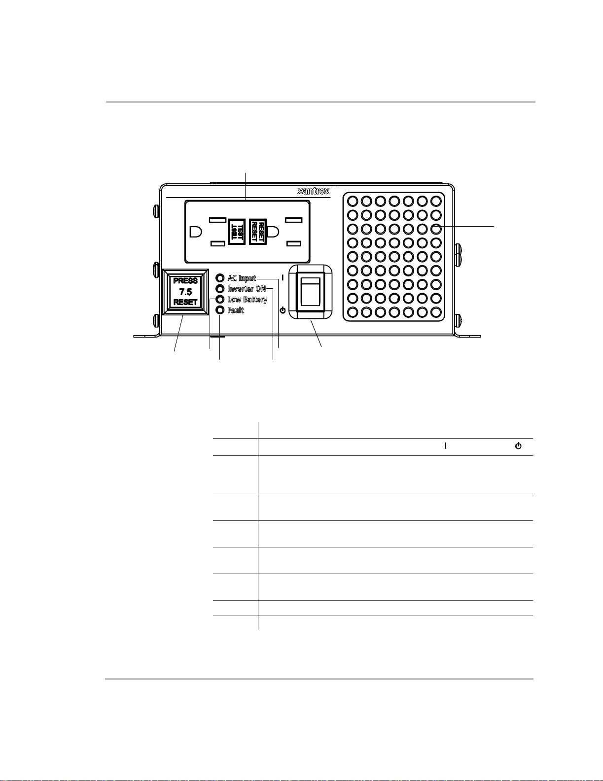
XS400 Features
Front Panel
7
8
Figure 1-1
\
6
4
5
Front Panel of the XS400
Table 1-1
Feature Description
1
2 AC Input light illuminates when you are connect ed to shore power .
3 Inverter ON light illumi nates onl y when th e XS400 is operat ing in
4 Low Battery light illuminates when your battery voltage is lower
5 Fault light illuminates for fault conditions such as over
6 Supplemental Circuit Protection button trips if there is an over-
7 GFCI outlets for connecting your appliances.
8 Ventilation openings provide air circulation for peak performance.
On/Standby Switch turns the inverter to On ( )
(Shore power refers to the AC input power from a utility grid,
generator or external AC source.)
inverter mode.
than 10.7 volts.
temperature, out put overload, or battery over voltage.
current (over 7.5 amps) or a short circuit.
2
1
3
Front Panel Features
or to S tandby ().
1–4 975-0054-01-01
Page 21
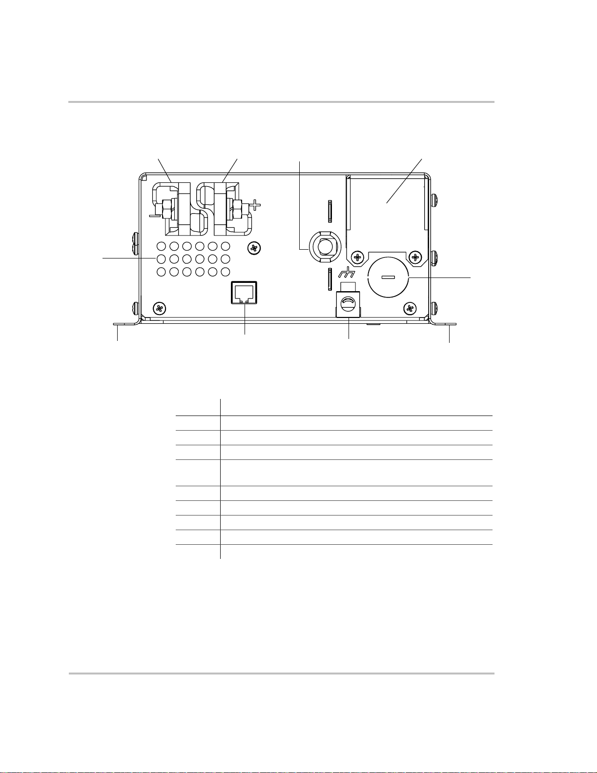
Back Panel
XS400 Features
9
Figure 1-2
12
8
Back Panel of the XS400
Table 1-2
Feature Description
1 DC terminal , negative
2 DC termi nal, positive
3 AC input cord for shore power
4 Wiring box access panel (For a view with the panel removed, see
5 Knockout for AC output hardwiring
6 Chassis ground lug
7 Remote switc h jack
8 Mounting flang es
9 Ventilation openings provide air circulation.
3
7
Back Panel Features
“Completing the Hardwiring” on page 2–21.)
6
4
5
8
975-0054-01-01 1–5
Page 22
Introduction
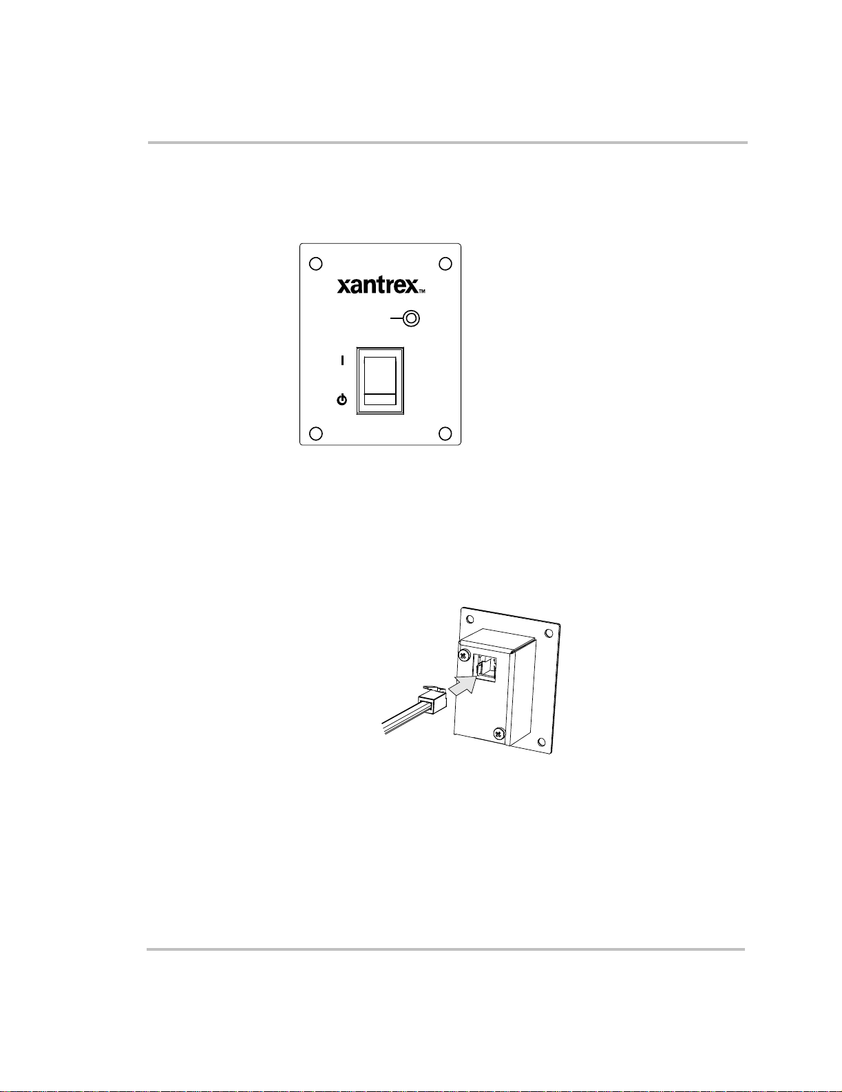
S400 Remote Switch
Front Panel
Inverter ON
Back Panel
Figure 1-3
The On/Standby switch provides remote control when the XS400 is
operating in invert mode.
Figure 1-4
The telephone cable connects to the remote switch jack in the back.
S400 Remote Switch
Connecting Cable to the S400 Remote Switch
1–6 975-0054-01-01
Page 23
2
Installation
Chapter 2, “Installation”, provides detailed information for
installing the XS400 and the S400 Remote Switch. This
chapter provides:
• a system diagram
• safety instructions and installation codes that must be
observed during installation
• a list of installation tools and materials
• detailed installation procedures
• chassis ground and DC cabling information
• procedures for hardwiring the AC output
• an illustration of inverter dimensions
CAUTION
Be sure to read all instructions befor e installing and operating
the XS400.
Page 24
Installation
Introduction
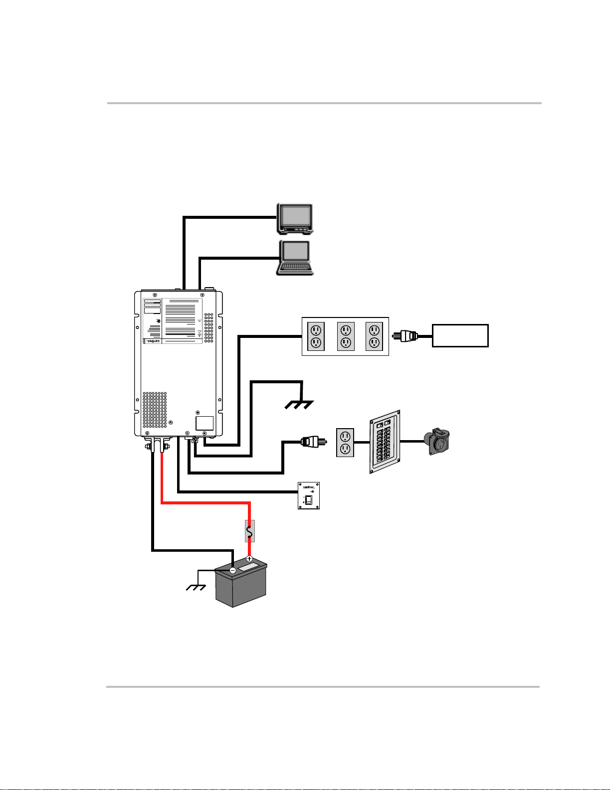
The system diagra m shown in Figure 2-1 is the basic installat ion. Review
this diagram carefully be f ore installing the XS400.
INVERTER
GFCI OUTLET
GFCI OUTLET
AC HARDWIRING
TELEVISION
COMPUTER
AC PLUG
Inverter ON
AC OUTLETS
S400 REMOTE
SWITCH
MAIN
AC PANEL
ADDITIONAL
LOADS
AC IN
(SHORE POWER)
DC FUSE AND DISCONNECT
OR
DC CIRCUIT BREAKER
XS400 Configuration
BATTERY (S)
Figure 2-1
2–2 975-0054-01-01
System Diagram
Page 25
Preparing for Installation
Read this entire installation chapter so you can plan the installation from
beginning to end. Prior to beginning your installation, review the
“Important Safety Ins tructions” on page vii.
WARNING: Electrical shoc k and fire hazards
Xantrex recommends all wiring be done by qualif ied personne l.
Disconnect all AC and DC power sources to prevent accidental
shock. Disable and secure all AC and DC disconnect devic es
and automatic generator starting devices.
It is the installer’ s responsibility to ensure complia nce with all
applicable installation codes a nd regulations.
WARNING: Fire hazard
T o meet regulatory requirements , the XS400 must be mounted
on a flat horizontal surface with the front panel in the upright
position.
Preparing for Installation
Installation Code s
It is the installer’s responsibility to determine which codes apply and to
ensure that all applicable installation requirements are met.
Applicable insta llation codes vary depending on the specific location and
application of the installation. Some examples are:
• The U.S. National Electri cal Code (NEC)
• The Canadian Electrical Code (CEC)
• Canadian Sta ndards As soci ation (CSA), a nd RV Indust ry Associati on
(RVIA) requirements for installation in RVs.
WARNING: Restrictions on Use
The XS400 Sine W ave Inverter shall not be used in
connection with life support systems or other medical
equipment or devices.
975-0054-01-01 2–3
Page 26

Installation
Materials List
Your XS400 Sine Wave Inverter package includes:
• One XS400 Sine W ave Inverter
• One S400 Remote Switch
• 25 ft. (7.5 m) telephone cable
• XS400 Sine Wave Inverte r Owner’s Guide
After you unpack your XS400, be sure to record the product information
in the form “Information About Your System” on page WA–4.
If any of these materials are missing or unsatisfactory, please contact
Customer Service.
Telephone 1-800-670-0707 (tol l free in North America)
1-604-422-2777 (direct)
Fax 1-604-420-2145
Email CustomerS ervice@xantrex.com
Web www.xantrex.com
Installation Tools and Materials
Tools
You will need the following tools and materials to instal l the XS400 and
the S400 Remote Switch:
To install the XS400, you need:
❐ Phillips screwdriver : #2
❐ Slot screwdrivers: 1/8 inch and 1/4 inch
❐ Wrench for DC terminals: 10 mm or adjustable
❐ Wire stripper
T o install the S400 Remote Switch, you ne ed:
❐ Power drill with 1/8-inch bit
❐ Jigsaw (optional)
❐ Feed wire (optional)
2–4 975-0054-01-01
Page 27

Materials for XS400 and S400 Remote Switch
T o install the XS400 and S400 Remote Switch, you require:
❐ DC cables (See Table 2-1 on page 2–9.)
❐ Appropriately sized connectors. Two DC connectors suitable for ¼
inch (6 mm) that go on the DC input cable te rminals. The other cable
connectors will depend on your installation.
❐ Crimping tool for fastening lugs and terminals on DC cables (You
may find it more conve nient to have the cri mp connect ors attache d by
the company that sells you the cable.)
❐ DC fuse and Disconnect or DC circuit breaker (See page 2–9.)
❐ Four #10 hardware fasteners to mount the XS400
❐ Four #6 self-tapping screws to mount the S400 Remote Swit ch
Materials for AC output hardwiring
❐ Cable requirements:
• within the range of No. 14 to No. 18 AWG (minimum size)
• 3 conductors
• solid or stranded
Preparing for Installation
❐ 1/2 inch cable clamp
975-0054-01-01 2–5
Page 28

Installation
Instal ling the XS400
Overview
This chapter provides detailed information on installing the XS400. The
overall procedure is divided into twelve steps:
1. Designing your installation (page 2–6)
2. Mounting your inverter (pa ge 2–10)
3. Connecting the chassis ground (page 2–11)
4. Installing the S400 Remote Switc h
5. Getting ready to connect the DC cables (page 2–14)
6. Routing the DC cables (page 2–15)
7. Connecting the DC cables (page 2–16)
8. Connecting your applian ces to the GFCI outlets (page 2–18)
9. Hardwiring the AC output (page 2–19)
10. Performing checks prior to initial start-up (page 2–22)
11. Connecting the AC input cord (page 2–22)
12. Testing your installation (page 2–23)
(page 2–12)
Step 1: Designing Your Installation
Before doing anything else , you need to determine how you are going to
use your XS400, and then design a power system that will give you
maximum performance. The more thorough your pla nning, the better
your power needs will be met. In particula r, you will need to:
• Be aware of installation cod es
• Choose an appropriate loca tion
• Calculate your batte ry requirements and appropriate battery size
• Calculate the DC cable size
• Select the correct DC fuse and Disconnect or the DC circuit breaker
Installation Codes
See “Installation Codes” on page 2–3 for more information.
2–6 975-0054-01-01
Page 29

Choosing a Location
:
Installing the XS400
WARNING: Risk of fire or explosion
This equipment contains compone nts that could produce arcs or
sparks. To reduce the risk of fire or e xplo sion, do no t ins tall th is
equipment in compartments containing batteries or flammable
materials, or in locations that require ignition-protected
equipment. This includes any space conta ining gasolinepowered machinery, fuel tanks, or joints, fittings, or other
connections between components of the fuel system.
WARNING: Fire hazard
Do not cover or obstru ct the venti lation openings. Do not inst al l
this equipment in a compartment with limite d airf low.
Overheating may result.
The inverter should only be installed in a location tha t meets the
following requirements:
Dry Choose a dry location. Do not allow water or ot her fluids
to drip or splash on the inverter. Do not expose to rain,
snow or splashing water.
Cool Normal air temperature should be between 32 °F (0 °C)
and 104 °F (40 °C) — the coole r the better within th is
range.
Ventilated The inverter requires air circulation to maintain optimum
operating temperat ure and provide best performance. If the
unit has inad equate ventilat ion, it may shut down due to
overheating. Allow as much space a round the ventilation
openings as possible. Xantrex recommends that othe r
objects be at least 3 inches (76 mm) away from the
ventilation openings for best performance. The air vented
through the openings should also have a path to circulate
away from the invert er.
Safe Do not inst all the inverter in t h e same compartment as
batteries or in any compartment containing flammable
liquids like gasoline.
975-0054-01-01 2–7
Page 30

Installation
Battery Requirements
Close to
battery
compartment
Protected
from battery
acid and
gases
Orientation To meet regulatory requirements, the XS400 must be
Long DC cables must be very la rge (and expensive), so
they should be kept s hort (see Table 2-1 on page 2–9).
However, the unit should NOT be installed in the battery
compartment due to the possible presence of explosive
hydrogen gas from the batteries.
Never allow ba ttery acid to drip on the inverter or its
wiring w h en fi ll in g the batteries or re ad ing their s p ec if i c
gravity. Do not mount the unit where it will be exposed to
gases produced by the batteries. These gases are corrosive
and prolonged expo sure will damage the inverter.
mounted on a flat hor izo ntal s urface with t he fron t panel in
the upright position.
CAUTION
The XS400 Sine Wave Inverter must only be connected to
batteries with a nominal output volta ge of 12 volts. The XS400
Sine W ave Inverter will not operate from a 6 volt battery and
will be damaged if connected to a 24 volt battery.
The batteri es that you u se str ongl y af fect t he performanc e of t he XS400. It
is important to connect the inve rter to the correct size and type of battery.
See Appendix B, “Battery Types and Sizes” on page B–1 for more
information.
2–8 975-0054-01-01
Page 31

DC Cables
Installing the XS400
For the best load starting perf ormance, the DC cables should be as short
and large as possible . S ee Table 2-1 for minimum recommended cable
size. Using a smaller cable may cause the inve rter to shut down under
heavy load. A larger cable may be used.
Table 2-1
Cable Length: Battery to Inverter
(each cable)
0–10 feet (0–3 meters) No. 6
10–15 feet (3–4.5 meters) No. 4
15–30 feet (4.5–9 meters) No. 2
30–40 feet (9–12 meters) No. 0
Minimum Recommended DC Input Cable (copper) — AWG
DC Fuse and Disconnect or DC Circuit Breaker
If you are using a DC fuse and Disconnect, a maximum 80 amp Class T
fuse shall be used for the DC fuse. A fuse of lower rating can be used, but
it shall not be lower than 60 amp Class T. The Disconnect shall be rated at
least 50 amps.
Alternately, a DC circuit breaker rated 50 amps can be used.
Minimum Recommended
Cable Size — AWG
975-0054-01-01 2–9
Page 32

Installation
Step 2: Mounting Your Inverter
Mount your inverter before you connect any wires or cables.
For your convenience, the inverter dimensions are provided in
Figure 2-9 on page 2–25.
WARNING: Fire hazard
T o meet regulatory requirements , the XS400 must be mounted
on a flat horizontal surface with the front panel in the upright
position.
To mount your XS400:
1. Turn the On/Standby switch on the front panel of the inverter to
Standby ( ) position.
2. Select an appropriate mounting location and orientation.
See “Choosing a Location” on page 2–7.
3. Hold the inverter against the mounting surface, mark the position of
the mounting screws, and then remove the inve rter .
OR
Use “Inverter Dimensions” on page 2–25 to mark the position of the
mounting screws.
You can also download a full scale version of the mounting template
from www.xantrex.com
4. Pilot drill the four mounting holes.
5. Fasten the inverter to the mount ing surface with four #10 hardware
fasteners.
2–10 975-0054-01-01
Page 33

Step 3: Con necting the Chassis Ground
The chassis ground lug is used to connect the chass is of the inverter to
your system’s chassis gro unding point, as required by installation codes.
Use copper cable tha t is either bare or pr ovided with green insulation. Do
not use the chassis ground lug for your AC output grounding wire.
To connect the chassis ground:
Refer to Figure 2-2.
1. Using the 1/4 inch slot screwdriver, loosen the screw on the chassis
ground lug.
2. Connect a No. 8 AWG copper cable between the inverter’s chassis
ground lug and the DC grounding point for your system.
In an RV or vehicle installation, this will usually be the vehicle
chassis or a dedicated chassis ground bus.
3. Tighten the screw to a torque of 6–7 lbf-in (0.68–0.79 Nm).
Installing the XS400
Figure 2-2
975-0054-01-01 2–11
Connecting the Chassis Ground
Page 34

Installation
Step 4: Instal ling the S400 Remote Switch
WARNING: Shock hazard
Before making an opening in a wall, bulkhead or panel, ensure
there is no wiring or other obstruction within the wall.
WARNING: Shock hazard
Ensure both the S400 Remote Switch and the XS400 are in
Standby ( ) mode before installing.
Installing the S400 Remote Switch is optional. The XS400 operates
normally without the remote switch.
The S400 Remote Switch is designed to be flush mounted on a wall,
bulkhead or panel. A 25 foot (7. 5 meter) telephone cable is supplied with
the remote switch.
If you want to extend the cable, use a high quality, 4-wire telephone
extension cable with 6-position, 4-contact connectors. The maximum
recommended cable length is 50 feet (15 meters).
For your convenience, a full scale mounting template is provided. See
“S400 Remote Switc h Mounting Template ( Scale approximately 1:1)” on
page 2–27.
Note: The S400 Remote Switch connects to a jack at the back of the
inverter. See “System Diagram” on page 2–2.
To install the remote switch:
1. Choose a location tha t is dry , free from corrosive or explosive fumes,
and otherwise appropria te for installing an electronic device.
2. Using the template, pilot-drill the mounting holes. Cut an opening
about 2 inches x 1.2 in ches (50 mm x 30 mm) and 1. 4 inche s (35 mm)
deep.
3. Route the telephone cable inside the wall and through the opening to
the inverter.
2–12 975-0054-01-01
Page 35

Installing the XS400
4. Connect one end of the telephone cable to the back of the inverter as
shown in Figure 2-3.
Figure 2-3
Conne c ting Cabl e to the XS400
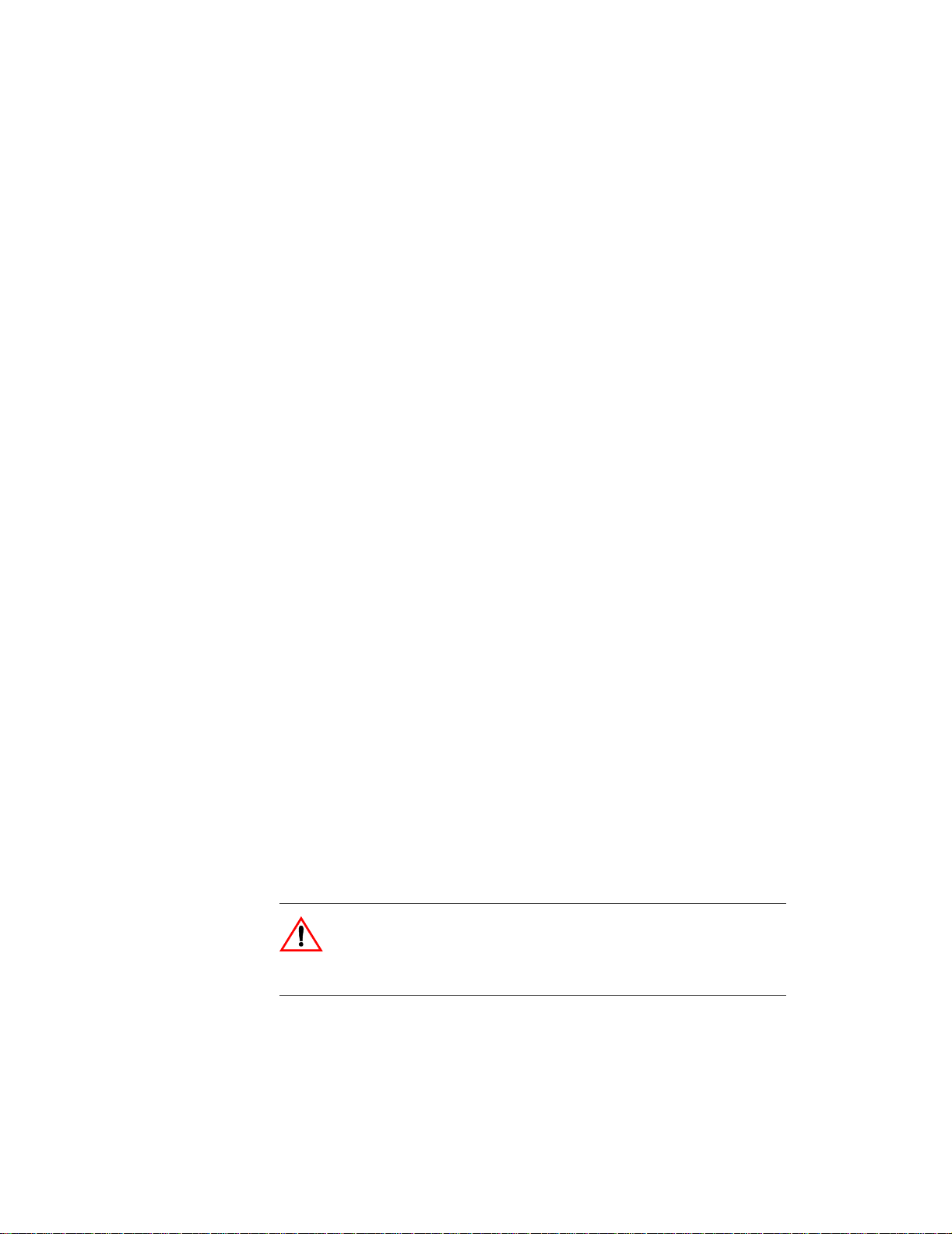
5. Connect the other end of the telephone cable to the remote switch as
shown in Figure 2-4.
Figure 2-4
Connecting Cable to the S400 Remote Switch
6. Place the remote switch in the opening and secure it with the four #6
fasteners.
975-0054-01-01 2–13
Page 36

Installation
Step 5: Getting Ready to Con nect the DC Cables
The DC cables should be as short as possible and large enough to handle
the required c urrent, in acc ordance wit h the elect rical code s or r egulati ons
applicable to your insta llation. The minimum recommended DC cable
size is speci fied in Table 2-1 on page 2–9. For the recommended DC fuse
and Disconnect or DC circuit breaker, see page 2–9.
To prepare the DC cables:
Refer to Figure 2-5, “Connection Order for DC Cables” on page 2–16.
1. Cut the negative cable to the recommended length. (See Table 2-1 on
page 2–9 for DC cable size.) Strip off enough insulation so you can
install the terminal you will be using.
Xantrex recommends the use of crimp connectors such as a ring lug
type. The connector should be designe d for a 6 mm or 1/4 inch stud
size to connect t o the XS 400 Sine Wave Inverter. If a cr imp connector
is used, it should be cri mped using t he tool indi cate d by the connecto r
manufacturer.
2. Cut two lengths of positive cabl e. One cable (max imum 18 inches)
goes from the battery to the DC fuse and Disconnect or to the DC
circuit breaker. The other cable goes from the DC fuse and
Disconnect or to the DC circuit breaker to the positive DC terminal.
3. Attach the connectors to the ends of both cables. Make sur e no stray
wire strands protrude from the terminals.
2–14 975-0054-01-01
Page 37

Step 6: Routing the DC Cables
WARNING: Fire and shock hazard
Route the cables away from sharp edges which might damage
the insulation. Avoid sharp bends in the cable.
Guidelines for Routing the DC Cables
• Do not attempt to use the chassis in place of the battery negative
connection for groundi ng. The inverter requires a reliable return path
directly to the battery.
• T o reduce the chance of interfe rence, keep the positive and negative
cables close together—ideally, tied together at regular intervals as
shown in Figure 2-5, “Connection Order for DC Cables” on page 2–
16.
• T o ensure maximum perfor mance from t he inverter, do not route your
DC cables through a DC distribution panel, battery isolator, or other
device that will cause addi tiona l voltage drops. The exception is the
DC fuse and Disconnect or the DC circuit breaker which is required
to protect the DC wiring.
Installing the XS400
975-0054-01-01 2–15
Page 38

Installation
Step 7: Connecting the DC Cables
8
Battery
Figure 2-5
7
6
3
5
Connection Order for DC Cables
CAUTIO N: Rev ers e pol ar i ty
2
9
4
Inverter
1
Before making the final DC connection, c heck cable polarity at
both the battery and the inverte r. Positive (+) must be connected
to positive (+); negative (–) must be connected to negative (–).
Reversing the positive (+) and negative (–) battery cables will
damage the inverter and void your warranty.
WARNING: Fire hazard
Use only appropriately sized copper cable. Make sure all DC
connections are tightened to a torque of 2.2–2.6 lbf-ft
(3.0–3.5 Nm). Loose connections will overheat.
2–16 975-0054-01-01
Page 39

Installing the XS400
To connect the DC cables:
Connect the DC cables as shown in Figure 2-5, in the order shown by the
numbers.
1. Switch the On/Standby switch to the Standby ( ) position.
2. Route the DC cables from the battery bank to the inverter. See “Step
6: Routing the DC Cables” on page 2–15.
3. Install a DC fuse and Disconnect or a DC circuit breaker in the
positive side of the circuit within 18 inches of the battery.
This protects your batte ry and wiring in case of accidental shorting.
(See “DC Fuse and Disconnect or DC Circuit Breaker” on page 2–9
for recommended fuse size and type.) Open the DC fuse and
Disconnect or turn of f the DC circuit breaker.
4. Connect one connector on the POSITIVE (+) cable to the POSITIVE
DC terminal on the inverter. Tighten the nut to a torque of
2.2–2.6 lbf-ft (3.0–3.5 Nm).
5. Connect the other connector to the posi tive (+) terminal DC fuse and
Disconnect or to the DC circuit breaker. Use a wrench to tighten the
connection according to the manuf acturer’s recommendat ions. Test
that the cable is secure.
6. Attach a short DC cable from the unconne cted end of the DC fuse a nd
Disconnect or DC circuit breaker. Tighten appropriately.
7. Observing polari ty carefully, connect the other end of the fused cable
to the POSITIVE (+) terminal of the battery. Tighte n this connection
to the battery manufacturer’s recommended torque.
8. Connect one connector on the NEGATIVE (–) cable to the
NEGATIVE (–) battery terminal. Tighten the connection according to
the battery manufactur er’s recommended torque .
9. Check that the polarity of the DC connections is correct: positive (+)
on the inverter is connected to the positive (+) on the battery, and
negative (–) is connect ed to the negative (–).
10. Connect the other connector of the NEGATIVE (–) cable onto the
NEGATIVE (–) terminal on the XS400 Sine Wave Inverter.
11. Use a wrench to tighten the nut to a torque of
2.2–2.6 lbf-ft
(3.0–3.5 Nm). Test that the cable is secure.
975-0054-01-01 2–17
Page 40

Installation
Step 8: Connecting Your Appliances to the GFCI Outlets
To connect your AC appliances to the GFCI outlets:
1. Turn the inver ter’s On/Sta ndby switch to Standby ( ).
2. Turn your AC applianc es off.
3. Connect your AC appliances to the GFCI outlet s in the fro nt panel.
4. If you wish to connect more appliances, use a multiple-outlet
extension cord. Ensure that the total power drawn does not exceed
400 watts.
Note: Ensure that the Reset button on the GFCI outle ts is not tripped.
Important:
inverter, Xantrex recommends that they be hardwired. See “Step 9:
Hardwiring the AC Output” on page 2–19.
If you have more permanent loads to connect to the
2–18 975-0054-01-01
Page 41

Step 9: Hardwiring the AC Output
If you wish to permanently connect additional AC outlets, Xantrex
recommends hardwiring the AC output connections.
WARNING: Fire, shock, and energy hazards
Make sure wiring is disconnected from all electrical sources
before handling. All wiring must be done in a ccordance with
local and national electrical wiring codes. Do not connect the
output leads of the inverter to any incoming AC source.
To ha rd w ire the AC outp ut co nn ections:
1. Turn the On/Standby switch to Standby ( ).
2. Remove the knockout using a slot screwdriver as shown in
Figure 2-6. Do not leave the knockout inside the wiring box.
Installing the XS400
Figure 2-6
975-0054-01-01 2–19
Removing the Knockout
Page 42

Installation
3. Locate the wiring box access panel, and remove the three screws to
access the wiring box as shown in Figure 2-7.
Figure 2-7
Removing the 3 Screws on the Wiring Box Access Panel
4. Remove the wiring box access panel from the unit.
5. Install a 1/2 inch cable clamp.
6. Locate the terminal block.
The three terminals are labelled as follows:
• L Line
• N Neutral
• Ground
7. Strip about 2 inches (50 mm) off the jacket of the AC output cable.
The AC output cable must be either solid or stranded, within the
range of No. 14 to No. 18 AWG, and have three conductors.
8. Strip approxi mately 3/8 inch (10 mm) off the insulation of the cable.
9. Run the AC cable through the cable clamp and into the wiring box.
10. Using the 1/8 inch slot screwdriver, loosen the wire attachment
screws on the terminals by five turns.
11. Insert and fasten the Ground wir e into the corresponding terminal.
12. Insert the Line and Neutral wires into the corresponding terminals.
2–20 975-0054-01-01
Page 43

Installing the XS400
13. Tight en the wire attachment screws to a torque of 1.3–1.8 lbf-ft
(1.76–2.44 Nm) as shown in Figure 2-8. Leave some slack inside the
output wiring box.
14. Secure the cable clamp on the cable jacket .
15. Attach the wiring box access panel and tighten the three screws.
Figure 2-8
975-0054-01-01 2–21
Completing the Hard wi ring
Page 44

Installation
Step 10: Performing Checks Prior to Initial Star t-up
Before starting up your inverter, ensure these conditions are met:
❐ Chassis ground is properly insta lled
❐ On/Standby switch is in the S tandby ( ) position on both the XS400
and S400 Remote Switch
❐ Positive (+) battery cable is connected to the positive (+) battery
terminal through the DC fuse and Disconne ct or DC circuit breaker
❐ Negative (–) battery cable is connected to the negative (–) battery
terminal
❐ Battery voltage is within the prope r range for this unit
(10.3–15.3 volts DC)
❐ DC Fuse is intact (not blown)
Step 11: Connecting the AC Input Cord
WARNING: Shock hazard
Connect the AC input cord only to a properly grounded
standard 120 volts AC, 15 or 20 amp receptacle. If the correct
type of receptacle is not available, have an electrician install
one.
WARNING: Shock hazard
When the On/Sta ndby switc h i s in the S tandby ( ) position a nd
the XS400 is connected to shore power , AC voltage will be
present at the output of the inverter.
To co nn ect the AC input cord:
◆ Plug the AC input cord into a properly grounded 120 volts AC, 15 or
20 amp receptacle, connecte d to an external shore power source such
as a utility grid or a generator.
2–22 975-0054-01-01
Page 45

Step 12: Testing Your Installation
WARNING: Shock hazard
The On/Standby switches on the XS400 and the S400 Remote
Switch do not disconnect DC or AC input power to the XS400.
There are two tests to be performed. The first test verifies that the XS400
operates in invert mode. The second test verifies that the XS400 operates
in shore power mode.
When you are re ady to test your installation and operate the XS400, close
the DC fuse and Disconne ct or the DC ci rcuit br eaker t o sup ply DC powe r
to the XS400.
Testing in Invert Mode
To test the XS400 in invert mode:
1. Ensure that shore power is discon necte d.
2. Turn the inver ter’s On/St andby switch to the On ( ) position. Turn the
On/Standby s witch on the S400 Remote Switc h to the On
Installing the XS400
() position.
The green Inverter On indicator illuminates.
3. Plug an appliance of 400 watts or less into one of the GFCI outlet s.
4. Turn the applia nce on to verify that it operates.
5. If the appliance operates, your installation is successful.
6. If the red Fault light illumi nates, see “Troubleshooting” on page 4–1.
Testing in Shore Power Mode
To test the XS400 in shore power mode:
Note: Shore power (pass-through) refers to the AC input power from a
utility grid, generator or external AC source
1. Connect to the shore power sour ce.
The XS400 transfers the applia nces to shor e power with the
On/Standby swit ch of the inverter or the S400 Remote Switch in
either the On ( ) or Standby ( ) position. The green AC Input light
illuminates.
2. Plug an appliance of 400 watts or less into one of the GFCI outlet s.
3. Turn the applia nce on to verify that it operates.
.
975-0054-01-01 2–23
Page 46

Installation
4. If the appliance operates, your installation is successful.
5. If your appliance doesn’t operate, refer to “Troubleshooting” on
page 4–1.
2–24 975-0054-01-01
Page 47

Installing the XS400
Figure 2-9
Inverter Dimensions
This drawing is not to scale. A full scale mounting template is available at www.xantrex.com
975-0054-01-01 2–25
Page 48

2–26
Page 49

Installing the XS400
2.5" (63.5)
2.1" (53.5)
0.2" TYP (5.0)
Inverter ON
0.2" TYP (5.0)
1.6" (40.8)
2" (50.8)
CUTOUT PANEL 2" X 1.2" (50.8 X 30.5)
(DASHED LINE)
DRILL Ø0.125 (1/8") HOLE
4 PLACES FOR #6/32 SELF
TAPPING SCREW
1.1" (28.3)
Figure 2-10
S400 Remote Switch Mounting Template (Scale approximately 1:1)
975-0054-01-01 2–27
Page 50

Page 51

3
Operation
Chapter 3, “Operation” explains how to use your XS400
effectively. This chapter explains how to turn the XS400 to
On () or Standby ( ) from the front panel or from the S400
Remote Switch, monitor the status of the XS400, and reset the
inverter.
CAUTION
Read this chapter before operating the XS400 Sine Wa ve
Inverter.
WARNING: Restrictions on use
The XS400 Sine W ave Inverter shall not be used in connection
with life support systems or other medical eq uipment or
devices.
Page 52

Operation
Front Panel Features
Before you begin to operate the XS400, review the front panel features in
Figure 3-1.
For a detailed description of each of the different features, see “Front
Panel of the XS400” on page 1–4 in the “Introduction” chapter.
7
8
Figure 3-1
\
6
4
5
Front Panel of the XS400
Table 3-1
Feature Description
1 On/Standby Switch
2 AC Input light
3 Inverter ON light
4 Low Battery light
5 Fault light
6 Supplemental Circuit Prote ction button
7 T wo GFCI outlets
8 Ventilation openings
21
3
Front Panel Fea tures
3–2 975-0054-01-01
Page 53

Operating the XS400
Operatin g th e XS4 0 0
The XS400 operates in either invert mo de or shore powe r mode.
Invert mode In invert mode, the XS400 powers your appliances from the battery. See
“Operating in Invert Mode” on page 3–5.
Shore power mode In shore power mode, the XS400 is connected to shore power and your
appliances are powered from the AC input power. See “Operating in
Shore Power Mode” on page 3–7.
Shore power (pass-through) refers to the AC input power from a utility
grid, generator or externa l AC source.
Turning the XS400 to On or to Standby
WARNING: Shock hazard
When the On/Sta ndby switc h i s in the S tandby ( ) position and
the XS400 is connected to shore power , AC voltage will be
present at the output of the inverter.
The On/Standby switc h on the XS400 turns the inverter to On () or to
Standby ( ) when operating in invert mode.
If you have installed the S400 Remote Switc h, you can also use the
remote switch to turn the XS400 to On
the S400 Remote Switch” on page 3–4.
The On/Standby switc h on the XS400 or the S400 Remote Switch is also
used to reset the inverter after a Fault condition. See “Resetting After a
Fault or Shutdown” on page 3–9.
() or to Standby ( ). See “Using
Important: The XS400 operates normally without the S400 Remote
Switch installed.
Turning the XS400 to Standby When Not in Use
If you won’t be using the XS400 for an extended period of time, turn the
inverter’s On/Standby switch to the Standby ( ) position . Turning the
switch to Standby ensu res that the XS400 draws no current from the
battery.
If you are disconnected from shore power with the XS400 On/Standby
swit c h in the On
( ) position, the XS400 draws very little current (about 1 mA) from the
battery.
975-0054-01-01 3–3
() position and the S400 Remote Switch in the Standby
Page 54

Operation
Using the S400 Remote Switch
The S400 Remote Switch performs the same function as the On/Standby
switch on the XS400.
Invert mode use
only
Purpose The S400 Remote Switch provides remote contr ol of the XS400 from a
Cable length You can use a longer cable up to a maximum recommended length of 50
The S400 Remote Switch provides On/Standby control only when the
XS400 is operating in invert mode.
T o use the S400 Remote Switch, the On/Standby swit ch on the XS400
must be turned to the On ( ) position. See “Operating in Invert Mode” on
page 3–5.
Important: When shore power is present, the S400 Remote Switch
will not change the operation of the inver ter.
convenient location of up to 25 feet (7.5 meters) away using the supplied
telephone cable.
feet (15 meters). Xantrex rec ommends using a high quality 4-wire
telephone cable with 6-position, 4-contact connectors.
Inverter ON
Figure 3-2
3–4 975-0054-01-01
S400 Remote Switch
Page 55

Operatin g in In v ert Mode
In invert mode, the XS400 power s your appl iances fr om the batter y. If the
On/Standby swit ch on both the XS400 and the S400 Remote Switch are
turned to On ( ), the XS400 automatically supplies your appliances with
inverter power if the shore power source fails or becomes disconnected.
To operate the XS400 in invert mode:
1. Disconnect the XS400 from shore power.
Operating in Invert Mode
2. Turn the On/Standby switch on the XS400 to the On
The Inverter ON light illuminates on the XS400.
AND
If you have installed the S400 Remote Switch, turn the S400 Remote
Switch to On
The Inverter ON light illuminates on the S400 Remote Switch.
3. Operate your appliances.
Important: The XS400 operates normally without the S400 Remote
Switch installed.
If you are not using th e XS400, see “T urni ng the XS400 to Sta ndby When
Not in Use” on page 3–3.
().
() position.
975-0054-01-01 3–5
Page 56

Operation
Recharging Your Batteries When Low Batter y Light Illuminates
Low battery If the Low Battery light illuminates on the XS400 while it is ope rating,
your battery level is low (less than 10. 7 volts). As long as the Inverter ON
light is illu minated on th e XS400, the unit wi ll conti nue to supply invert er
power to your appliances.
However, Xantrex highly recommends that you recharge your batteries.
Turn off your appliances and recharge your battery. When the Low
Battery light turns of f (12.6 volts), you can restart your appliances. See
“Restarting or Operating Multiple Appliances”.
Importance of
recharging
More information For more informat ion about batt ery c harge rs and batt ery monitor s, se e the
Xantrex recommends that you recharge your batteries before they are
50% discharge d. This gives t hem a much longe r life cycl e than r echargi ng
them when they are almost completely discharged. See “Battery State of
Charge” on page B–8.
Xantrex web site at www.xantrex.com
Recovering from Low Battery Voltage Shutdown
If the Low Battery light illumi nates and the Inverter ON light on the
XS400 turns off when you are operating the unit, the XS400 has shut
down due to low batter y voltage ( 10.3 volts) . Output power is inter rupted.
To recover from a low battery voltage shutdown:
1. Turn off your appliances and recharge your battery.
2. When the Low Battery li ght turns off (12. 6 volts) and th e Inver ter ON
light illuminates, you can restart your appliances.
Restarting or Operating Multiple Appliances
The XS400 can handle several appliances simultaneously as long as they
do not draw more than 400 watts in total.
To restart or operate several appliances:
◆ Turn them on separately after the XS400 has started.
This action ensures that the XS400 does not have to deliver the
starting curren t for all the loads at once and helps to prevent an
overload shutdown.
3–6 975-0054-01-01
Page 57

Operating in Shore Power Mode
Operating in Sh ore Power Mode
Definition Shore power (pass-through) refers to the AC input power from a utility
grid, generator, or external AC source.
Shore power mode In shore power mode, the XS400 is connected to shore power and your
appliances are powered from the AC input power.
Transfer to in v ert
mode
S400 Remote
Switch
The transfer to inverter power will oc cur if shore power is present, but
either the shore power voltage is too low (less than 85 volts AC) or too
high (greater than 140 volts AC). In this c ase, the transfer from shore
power to inverter power prevents damage to your appliances.
You cannot use the S400 Remote Switch to control the XS400 when it is
operating in shore power mode.
Important: The XS400 transfers the appliances to shore power
whenever shore power is connected, r egardless of the position of the
On/Standby swit ches.
To operate in shore power mode:
1. Connect the XS400 to shore power.
The AC Input light on t he XS400 illuminate s. The On/S tandby s witc h
on both the S400 Remote Switch a nd the XS400 can be either On
or in Standby ( ) position.
2. Operate your appliances.
()
975-0054-01-01 3–7
Page 58

Operation
Monitoring th e I n dic a tor Lights
The four indicator light s on the front panel show you the operating status
of the XS400. See Table 3-2.
For an illustra tion of the indicator lights on the front panel, see “Front
Panel of the XS400” on page 3–2.
If none of the front panel lights are on, see “Troubleshooting Reference”
on page 4–2.
Table 3-2
Light Color Status Action
AC Input Green When the XS400 is connect ed to
Inverter ON Green When the XS400 is on, the Inverter
Low Battery &
Inverter ON
Low Battery Yellow When the Low Batte ry light
Fault Red The Fault light illuminates
Status of Indicator Lights
shore power , the AC Input light
illuminates.
ON lig ht illum in ates.
Yellow &
Green
When both lights illuminate, your
battery level is low. (The battery
voltage has dropped below 10.7
volts DC.)
illuminate s, your battery level is
critically low. (The battery voltage
has dropped below 10.3 volts DC.)
whenever there is a battery overvoltage fault condition (exceeds
15.3 volts), output overload fault
condition or over-temperature fault
condition.
You can run all your applian ces f rom
shore power.
You can run your appliances from
the batt er y.
You can run your appliances but
your battery level is low. Charge
your battery or connect to shore
power.
You cannot run appliances. Charge
your battery or connect to shore
power.
You cannot run appliances as the AC
output is disabled in invert mode.
Clear the fault condition. Reset the
XS400 by turning the On/Standby
switch on the XS400 or the S400
Remote Switch to Standby
then to On ( )
power.
() and
, or connect to shore
3–8 975-0054-01-01
Page 59

Resett in g A f ter a Faul t or Sh u tdown
This section provides explanations and procedures for resetting the
XS400 after a fault or shutdown.
If you are una ble to resolve the pr oblem after refer ring to Table 3-3, refer
to the “Trouble shooting” section on page 4–2.
Resetting After a Fault or Shutdown
Table 3-3
Fault Status Action
Shutdown The XS400 needs to be reset . Turn the On/Standby switch on either t he
Short circuit If ther e is a s h or t cir c uit, the
Ground Fault When a fault condition is
Rese tting After A Fault or Shutdown
Supplemental Circuit Protection
button trips.
detected , the Reset button on the
GFCI outl et trip s and po wer t o the
appliances is interrupted.
inverter’s front panel or the S400 Re mote
Switch to Standby ( ) and then to On ( ).
Remove the short circuit then press the
Supplemental Circuit Prote ction button.
Reset: To resume normal operation,
determine and correct the ground fault,
then press the Res e t b utton.
Test: Press the Test button on the GFCI
outlet with either shore power and/or the
XS400 turned t o On ( ). The Reset button
should tr ip. Pr ess the Res et bu tto n t o re set
the GFCI and to continu e with normal
operation. This test should be performed
on a monthly basis.
If the Reset button does not trip, the GFCI
may have failed. Contact your deal er to
have a qu alified service person examine
the XS400.
Overload The XS400 is designed to provide
400 watts continuously and 800
watt s surge c apability for fiv e
seconds. If the connected
appliances draw more than the
rated power, the XS400 will shut
down and the red Fault li ght
illuminates.
975-0054-01-01 3–9
Disconnect the appliances connected to
the inverter and then turn the On/Standby
switch on e ither the inverter’s front panel
or the S400 Remote Sw itch to Standby
( ) and then to On ( ).
See also “Recharging Your Ba tteries
When Low Battery Light Illuminates” on
page 3–6.
Page 60

3–10
Page 61

4
Troubleshooting
The XS400 is designed for high reliability and has a number
of protection features for trouble free operation. If, however,
you have any problems operating your inverter or S400
Remote Switch, refer to the “Troubleshooting Reference for
the XS400” on page 4–3.
Read this troubleshooting chapter b efore calli ng your dealer or
Xantrex Customer Service on page ii.
If you cannot resolve the problem, record the information
asked for on the form, “Information About Your System” on
page WA–4. Providing this information to our Customer
Service Representatives will help them to assist you better.
Page 62

Troubleshooting
Troubleshooting Reference
WARNING: Electrical Shock and Fire Hazard
Do not disassemble the XS400. It does not contain any userserviceable parts. Attempting to service the unit yourself could
result in electrical shock or fire.
This section provides you with troubleshooting tips to identify and solve
most problems that can occur with the XS400 and S400 Remote Switc h.
Before contacting your dealer or customer service, please refer to the
tables, “T roubl eshooting Refer ence for t he XS400” and “T rouble shooting
Reference for the S400 Remote S witch”.
If you are unable to resolve the problem after referring to the
Trouble shooting Reference table s, contact your dealer or Xantrex
Customer Service.
Figure 4-1
For a detailed description of the different features, see “XS400 Features”
on page 1–4.
4–2 975-0054-01-01
Front Panel
Page 63

Troubleshooting Reference
Table 4-1
Problem Possible Cause Solution
No output voltage. No
indicator lights are
illuminated.
No ou t p ut volta g e . I n verter
ON lig ht is illuminate d .
Troubleshooting Reference for the XS400
The On/Sta ndby switch is in
Standby ( ) mode.
The S400 Remote Switch is
in Standby ( ) mode.
No input power to the
inverter.
DC fuse open (external)
Supplemental Circuit
Protection button has tripped.
GFCI has tripped.
Turn the On/S ta ndby swit ch on the inverte r
to On ( ).
Turn the On/Standby switch on the S400
Remote Switch to On ( ).
Check the DC wiring to the inverter for
loose conn ectio ns, frayed wiring o r a n ope n
DC Disconnect.
Have a qualified ser vice technician check
and repl ace the fuse.
Disconn ect all app l iances to reduce the
overload. Check the AC wiri ng and reset
the Supplementa l Circuit Protec tion button.
Clear the ground fault, and reset the GFCI
by pressing the Reset button on the GFCI.
No output v o ltage. Fault light
is illuminated.
975-0054-01-01 4–3
The inverter may be
overloaded.
Battery voltage may be too
high.
Over temp erature.
Disconnect all appliances connected to the
inverter, and reset the invert er by turning
the On/Sta ndby swit ch on eit he r the XS400
or S400 Remote Switch to Standby
and then to On ( ).
The inverter w ill restar t if the battery
voltage drops below 14.5 volts DC.
Allow the inverter to cool down. The
inverter will restart automatically.
()
Page 64

Troubleshooting
Table 4-1
Problem Possible Cause Solution
No output voltage. Low
Battery li ght is illuminate d.
Output voltage is present.
Inverter ON light and Low
Battery light are illumina ted.
AC input cord is con necte d to
shore power and the AC Input
light is off. The appliances
are not po w ered.
AC input cord is con necte d to
shore power and the AC Input
light is illum inated. The
appliances are not being
powered from shore power.
Troubleshooting Reference for the XS400
Battery voltage is too low.
Poor DC wiring.
Battery voltage is low. Disconnect all appliances. Charge the
The shore power voltage is
out of range (less than 85
volts AC or greater than 140
volts AC).
External breaker ha s tripped.
Supplemental circuit breaker
has tripped.
GFCI has tripped.
Recharge the battery to more than 12.6
volts DC. The inverter w ill restart
automatically.
Turn the inve rter to Standby
Disconnect the DC wiring. Us e prope r
wiring and ensure all connec tions are tight.
batteries.
Turn the On/Standby switch to On ( ), and
the appliance will be powered from the
inverter.
Reset the external breaker.
Disconnect all appliances. Check the AC
wiring and press the Supple mental Circuit
Protection button to reset it.
Clear the ground faul t and re set the GFCI.
().
AC input cord is con necte d to
shore power. AC Input light
illuminates intermitte ntly.
Fan does not turn on. The internal components of
4–4 975-0054-01-01
The shore power voltage is
close to being out of range
(less than 85 volts AC or
greater than 140 volts AC).
the inv er t er ar e n ot wa rm .
Turn On/S tandby switch to On ( ), and the
appliance will be powered from t he inverter
or shore power.
No action. The fan will run automat ically
when necessary to coo l th e internal
components of the inverter.
Page 65

Table 4-1
Problem Possible Cause Solution
Troubleshooting Reference for the XS400
Troubleshooting Reference
Fan runs all the time. The amount of power being
consumed by the app liance s
is high.
The ambient temperature is
high.
Table 4-2
Problem Possible Cause Solution
The S400 Remote Switch is
On ( ), but its Inverter ON
light is off.
Troubleshooting Reference for the S400 Remote Switch
The On/Standby switch on
the invert er is in St andby ( )
mode.
The cable connection is l oose
or faulty.
No action. The fan will run at lower speeds
and stop automatically when the internal
temp er at u r e of th e inv e r te r fal ls .
No action. The fan will run at lower speeds
and stop automatically when the am bient
temp erat u r e fa l ls.
For more information on the “Fan C ooling
System”, refer to page A–3.
Swit ch th e in v er t er to O n ( ).
Check the cable.
The S400 Remote Switch is
On ( ) and the Inverter ON
light is illum inated, but
appliances do not ope rate.
975-0054-01-01 4–5
The inverter is in faul t/
protection mode.
Check the lights on the front panel of the
inverter . If th e Fault light is illumina ted, see
Table 4-1, “Troubleshooting Reference for
the XS400” on page 4–3.
Page 66

4–6
Page 67

A
Specifications
Appendix A, “Specifications”, contains the electrical and
physical specifications for the XS400 and physical
specifications for the S400 Remote Switch.
All specifications are subject to change without notice.
Page 68

Specifications
Electrical Specifications of XS400
Output power at 12 VDC input
• Continuous
400 VA
(0 °C to 40 °C), derated
linearly to 300 VA at
122 °F (50 °C)
1
, 32 °F to 104 °F
• Surge capacity for 5 seconds
Input voltage 12 VDC nominal
Output voltage 120 VAC RMS ± 3 VAC
Output frequency 60 Hz ± 0.05 Hz
Output wave form Sine wave
Total harmonic distortion of output waveform <3%
High battery shutd own 15.3 ± 0.3 VDC
Low battery indicati on 10.7 ± 0.3 VDC
Low battery shutdown 10.3 ± 0.3 VDC
Maximum efficiency 88%
No load current draw with switch turned to On ( )
No load current draw with switch se t to Standby
Supplemental circuit protector 7.5 AAC
1.
The term “watts” has been used throughout the guide to refer to output
power. More correctly, the actual unit of power used is “VA”.
800 VA
10.3 to 15.3 VDC
1.25 ADC maximum
0 ADC
()
Physica l Specificat ion s of XS400 with P rojec tions
Length 13.5 inches (343 mm)
Width 7.36 inches (187 mm)
Height 3.27 inches (83 mm)
Weight 10 lb (4.54 kg)
A–2 975-0054-01-01
Page 69

Regulatory Approvals
CSA/NRTL approved to CSA C22.2 No. 107.1 and UL 458
FCC Class B
Transfer Circuit
Transfer circuit 6 Amps, 85 to 140 VAC
Fan Cooling System
A fan cools the internal heat generating components of the inverter. The
fan begins to operate when the int ernal tempe rature r ises
fan increases with internal temperature.
The fan turns off if the int ernal temperature of the inverter drops
Physical Specifications of S400 Remote Switch
Regulatory Approvals
. The speed o f the
.
Height 2.5 inches (63.5 mm)
Width 2 inches (50.8 mm)
Depth 1.1 inches (28.3 mm)
Cable length 25 feet (7.5 m)
975-0054-01-01 A–3
Page 70

A–4
Page 71

Battery Types and
B
Sizes
The batteries that you use strongly affect the performance of
the XS400. It is important to connect the inverter to the correct
size and type of battery.
The information in Appendix B will help you to select,
connect, and maintain batteries that are most appropriate for
your application.
Page 72

Battery Types and Sizes
Battery Types
Automotive Starting Batteries
The lead-acid battery you are most familiar with is probably the starti ng
battery in your vehicle. An automotive starting battery is designed to
deliver a lar ge amount of current for a short period of time (so it can start
your engine). Only a small portion of the battery’s capacity is used when
starting the engine, and the spent capacity is quickly recharged by the
running engine.
The starting battery in your vehicle is not designe d for repeated deepdischarge cycles where the battery is almost completely discharged and
then recharg ed. If a star ting battery is used in this kind of deep discharge
service, it will wear out very rap idly.
Deep-Cycle Batteries
Deep-cycle batteries are designed for deep discharge service where they
will be repeate dly discharged and recharged. They are marketed f or use in
recreational vehicles, boats, a nd electric golf carts—so you may see them
referred to as RV batteries, marine batteries, or golf cart batteries.
For most applications of the XS400, Xantrex recommends that you use
one or more deep-cycle batteries that are separated from the vehicle’s
starting battery by a batte ry isolator .
A battery isolator is a solid -state electronic circuit that allows equipment
to be operated from an auxilia ry batte ry without danger of discha r ging the
vehicle’s starting battery. During vehicle operation, the battery isolator
automatically directs the charge from the alternator to the battery
requiring the charge.
Battery isolators are available at marine and RV dealers and most auto
parts stores.
B–2 975-0054-01-01
Page 73

Battery Size
Battery Size
CAUTION
The XS400 Sine Wave Inverter must only be connected to
batteries with a nominal output volta ge of 12 volts. The XS400
Sine W ave Inverter will not operate from a 6 volt battery and
will be damaged if connected to a 24 volt battery.
Battery size or capacity is as important as the battery type for efficient
operation of your loads. Xantrex recommends that you purchase as much
battery capacity as you need.
A number of different sta ndards are used to rate battery energy stor age
capacity. Automotive and marine starting batteries are normally rated in
cranking amps. This is not a relevant rating for continuous loads like an
inverter. Deep-cycle batteries use a more suitable rating system, either
“amp-hours” (“Ah”) or “reserve capacity” in minutes.
Battery Reserve Capacity Battery reserve capacity is a measure of
how long a battery can deliver a certain amount of current—usually 25
amps. For example, a battery with a reserve capacity of 180 minutes can
deliver 25 amps for 180 minutes before it is completely discharged.
Amp-hour (Ah) Capacity Amp-hour capacity is a measure of how
many amps a battery can deliver for a specified length of time—usually
20 hours. For example, a typical mari ne or RV battery rated for 100 Ah
can deliver 5 amps for 20 hours (5 A x 20 hours = 100 Ah).
This same battery can deliver a higher or lower current for less or more
time, limited a pproxim ately by t he 1 00 Ah figu re (for example , 50 A f or 2
hours, or 200 A for 1/2 hour), but usuall y the capacity f igure given is only
accurate at the specified rate (20 hours).
T o calculate the battery capacity you require, read “Estimating Battery
Requirements” on page B–4 and “Battery Sizing Example” on page B–4,
and then complete the “Battery Sizing Worksheet” on page B–5.
975-0054-01-01 B–3
Page 74

Battery Types and Sizes
Estimating Battery Requirements
To determine how much ba tt ery ca pacity you need:
1. Determine how many watt s are consumed by each appliance that you
will operate from the XS400. You can normally find the watt rating
labelled on the product. If only the current draw is given, multiply it
by 115 to get the power consump tion in watts.
2. Estimate how many hours each appliance will be operating each day.
3. Calculate the daily watt-hours needed for each appliance.
4. Add the total number of watt-hours needed for all the appliances and
multiply it by the number of days between charges.
5. Divide the total watt-hour s of AC load between charges by 10. This
gives the battery Ah used be tween charges.
6. Double the total Ah used between charges to get the recommended
battery size in Ah.
See the battery sizing example that follows.
Battery Sizing Example
This battery sizing example illustrates a typical calculation, assuming an
opportunity to charge the batteries every three days:
.
Daily w att-hour s
(A) Power
Consumption
Appliance
TV 100 W 4 hours 400 Wh
VCR 100 W 4 hours 400 Wh
3 lamps, 60 W each 180 W 4 hours 720 Wh
Audio system 60 W 4 hours 240 Wh
DVD player 100 W 2 hours 200 Wh
Other loads 100 W 3 hours 300 Wh
Total daily watt-hour s of AC loa d 2260 Wh
x Number of days between charges 2
= Tot al watt-hours of AC load between char ges 4520 Wh
Battery Ah used between charges (divide by 10) 452 Ah
Recommended Batter y Bank Size in Ah (multiply by 2) 904 Ah
(Watts)
(B) Operating
Time p e r D ay
(Hours)
needed for this
appliance
(= A x B)
B–4 975-0054-01-01
Page 75

This example illustrates how quickly your battery needs can escalate. To
reduce the required battery size, you can conserve energy by elimina ting
or reducing the use of some loads or by re-charging more frequently.
When sizing your bat tery, resist the tempta tion to skip the last step of this
calculation (multiplying by 2) . More capacity i s bette r sinc e you wi ll h ave
more reserve capacity, be better able to handle large loads and sur ge
loads, and your battery won't be discharged as deeply. Battery life is
directly dependent on how deeply the battery is discharged. The deeper
the discharg e, the shorter the battery life.
Battery Sizing Worksheet
Use the following worksheet to calculate your battery needs. To ensure
sufficie nt battery capacity, be generous when estimating the operating
time per day for each of the loads you will run.
Appliance
Estimating Battery R e quirements
Daily w att-hour s
(A) Power
Consumption
(Watts)
W hours Wh
W hour Wh
(B) Operating
Time p e r D ay
(Hours)
needed for this
appliance
(= A x B)
W hours Wh
W hours Wh
W hours Wh
W hours Wh
Total daily watt-hour s of AC loa d Wh
x Number of days between charges
= Tot al watt-hours of AC load between char ges Wh
Battery Ah used between charges (divide by 10) Ah
Recommended Battery Bank Size in Ah (multiply by 2) Ah
975-0054-01-01 B–5
Page 76

Battery Types and Sizes
Using M u ltiple Batteries
As your power requir ements incr ease, yo u may need to use mor e than on e
battery to obtain sufficient capacity. Read “Two Batter ies Connected In
Parallel” on p age B–6 and “Two Separate Battery Banks” on page B–6 to
determine whether two batte ri es or two battery banks are more
appropriate for your applications.
Two Batteries Connected In Parallel
Two identical batteries can be connected positive (+) to positive (+) and
negative (–) t o nega tive ( –) i n a par allel syste m. A par allel syste m doubles
capacity and maintains the voltage of a single battery.
CAUTION
Do not connect the following in parallel:
• batteries made by different manufacturers
• different types of batteries
• batteries that have different Ah ratings
Decreased battery life and improper charging will result .
Two Separate Battery Banks
If you need more than two batteries (or are using different makes or
models of batteries) , Xant rex recommends that you install two separate
battery banks and a battery selector switch.
By installing a battery selector switch, you can select between the two
battery banks, use both banks in parallel, or disconnect both banks from
the load. Battery selector switches are available at marine and RV dealers.
B–6 975-0054-01-01
Page 77

Battery Tips
Battery Tips
WARNIN G: Explosion and fire hazard
Review “Precautions When Working With Batteries” on
page viii before you work with the batteries in your system.
Explosive/Corrosive Gases Lead-acid bat teries may emit hydrogen
gases, oxygen, and sulfuric acid f umes when recharging. To reduce the
risk of explosion:
• Vent the battery compartment to prevent the accumul ation of gases.
• Do not install electronic or ele ctrical equipment in the battery
compartment.
• Do not smoke or use an open flame when working around batteries.
Temperature Sens itivi ty The capa city of lead-acid batteries is
temperature sensi tive. Battery capacity is rated at 77 ºF (25 ºC). At 0 ºF
(–20 ºC), the Ah capacity is about half the rated capacity. You should
consider temperat ure when designing your system.
• Low Temperatures If extremely low temperatures are expected
where the inverter is going to be located, you should consider a
heated equipment room. If the system is loc ated in an unheated
space, an insulated battery enclosure is recommended.
• High Temperatures The batteries should also be protected from
high temperatures. These can be caused by high ambient
temperatures, solar heating of the battery enclosure, or heat
released by a nearby engine or generator. High battery
temperatures short en battery life and therefore you should
ventilate the enclo sure and use shade and insulation as
appropriate.
Discharged Batteries Do not leave batte ries in a discharged state for
more than a day or two. They will undergo a ch emical process (sulfation)
that can permanently damage the battery. As well, batteries self-dischar ge
over a period of three to six months, and they should be recharged
periodically even if they a re not being used.
Electrolyt e Level If your batterie s are not the “maintenance-free” type,
check the electrolyt e leve l at least once a month. Excessive fluid loss is a
sign of overcharging. Replenish the electrolyte using only distilled water.
Battery Co nn ecti ons Connecti ons to battery posts must be made with
permanent connectors tha t pr ovide a reliable, low-resistance connection.
Do not use alligator clips. Clean the connections regularly and prevent
corrosion by using a protective spray coating or Vaseline.
975-0054-01-01 B–7
Page 78

Battery Types and Sizes
Battery State of Charge You can measure battery state of charge with
a hydrometer or approximate sta te of charge with a voltmeter. Use a
digital voltmete r that can display tenths or hundredths of a volt when
measuring 10 to 30 volts. Make your measurements when the battery has
not been charge d or dis char ged for se veral hours. For a deep- cycle batt ery
at 77 ºF (25 ºC), use the following table:
Battery Voltage State of Charge
12.7–13.0 100%
12.5–12.6 80%
12.3–12.4 60%
12.1–12.2 40%
11.9–12.0 20%
B–8 975-0054-01-01
Page 79

Warranty and Product
Information
Warranty
What does this warranty cover? This Limited Warranty is provided by Xantre x Technology , Inc.
("Xantrex") and cove rs defects in workmanship and materials in your XS400 Sine Wave Inverter and S400
Remote Switch. This warranty lasts for a Warranty Period of 12 months from the date of purchase at point of
sale to you, th e original end user customer.
What will Xantrex do? Xantrex will, at its option, repair or replace the defective product free of charge,
provided th at you notify Xantrex of the product defect within the Warranty Period, and provided that Xant rex
through inspection establi shes the existence of such a defe ct and that it is covered by this Limited Warranty.
Xantrex will, at its option, use new and/or reconditioned parts in performing warranty repair and building
replacement products. Xantrex reserves the right to use parts or products of original or im proved design in the
repair or replacement. If Xantrex repairs or replace s a product, its warranty continues for the remaining
portion of the original Warranty Period or 90 days from the date of the re turn shipment to the customer,
whichever is greater. All replaced products an d all parts removed from repaire d products become the property
of Xantrex.
Xantrex covers both parts and labor necessary to repair the product , a nd return shipment to the customer via a
Xantrex-selec ted non-expedited surface freight within the contiguous Unit ed States and Canada. Alaska and
Hawaii are excluded. Contact Xantrex Custome r Service for details on freight policy for return shipments
outside of the contiguous United States and Canada.
How do you get service? If your product requires troubleshooting or warranty service, contact your
merchant. If you are unable to contact your merchant, or the merchant is unable to provide service, contact
Xantrex directly at:
Phone: 1-800-670-0707 (toll free)
1-604-422-2777 (di r ec t)
Fax: 1-604-420-2145
Email: CustomerService@xantrex.com
Direct returns may be performed according to the Xantrex Return Mat erial Authorization Policy described in
your product manual. For some products, Xantrex maintains a network of regiona l Authorized Service
Centers. Call Xantrex or check our website to s ee if your product can be repaired at one of thes e fa cilities.
In any warranty claim, dated proof of purchase must accompany the pr oduct and the product must not have
been disassembled or modified without prior written authorization by Xantrex.
Proof of purchase may be in any one of th e following forms:
• The dated purchase receipt fr om th e original purchase of the produ ct at point of sale to the end user, or
• The dated dealer invoice or purchase receipt showing original equipment manufacturer (OEM) status, or
• The dated invoice or purchase receipt showing the product exchanged under warranty
975-0054-01-01 WA–1
Page 80

Warranty
What does this warr anty not cover? This Limi ted Warranty does not cover normal wear and te ar of the
product or costs rel ated to the removal, insta llation, or troubleshooting of the cus tom er's electrical systems.
This warranty does not ap ply to and Xantrex will not be responsible for any defect in or damage to:
a) the product if it has been misused, neglected, improperl y installed, physically damaged or altered, either
internally or externally, or damaged from improper use or use in an unsuitable environment;
b) the product if it has been subjected to fire, water, generalized corrosion, biological infestations, or input
voltage that creates operati ng conditions beyond the maximum or minimum limits lis ted in the Xantrex
product specifications including high input voltage from generators and lightning strikes;
c) the product if repairs have been done to it other than by Xantrex or its auth orized service centers
(hereafter "ASCs");
d) the product if it is us ed as a component part of a product expressly warranted by another manufact urer;
e) the product if its original identification (trade-mark, serial number) m arkings have been defaced, altered,
or removed.
Disclaimer
Product
THIS LIMITED WAR RANTY IS THE SOLE AND EXCLUSIVE WARRANTY PROVIDED BY XANTREX IN CONNECTION
WITH YOUR XANTREX PRODUCT AND IS, WHERE PERMITTED BY LAW, IN LIEU OF ALL OTHER WARRANTIES,
CONDITIONS, GUARANTEES, REPRESENTATIONS, OBLIGATIONS AND LIABILITIES, EXPRESS OR IMPLIED,
ST ATUTORY OR OTHER WISE IN CONNECTION WITH THE PRODUCT, HOWEVER ARISING (WHETHER BY CONTRACT,
TORT, NEGLIGENCE, PRINCIPLES OF MANUFACTURER'S LIABILITY, OPERATION OF LAW, CONDUCT, STATEMENT OR
OTHERWISE), INCLUDING WITHOUT RESTRICTION ANY IMPLIED WARRANTY OR CONDITION OF QUALITY,
MERCHANTABILITY OR FITNESS FOR A PARTICULAR PURPOSE. ANY IMPLIED WARRANTY OF MERCHANT AB ILITY
OR FITNESS FOR A PARTICULAR PURPOSE TO THE EXTENT REQUIRED UNDER APPLICABLE LA W TO APPLY TO THE
PRODUCT SHALL BE LIMITED IN DURATION TO THE PERIOD STIPULATED UNDER THIS LIMITED WARRANTY.
IN NO EVENT WILL XANTREX BE LIABLE FOR ANY SPECIAL, DIRECT, INDIRECT, INCIDENTAL OR CONSEQUENTIAL
DAMAGES, LOSSES, COSTS OR EXPENSES HOWEVER ARISING WHETHER IN CONTRACT OR TOR T INCLUDING
WITHOUT RESTRICTION ANY ECONOMIC LOSSES OF ANY KIND, ANY LOSS OR DAMAGE TO PROPER TY, ANY
PERSONAL INJURY, ANY DAMAGE OR INJUR Y ARISING FROM OR AS A RESULT OF MISUSE OR ABUSE, OR THE
INCORRECT INSTALLATION, INTEGRATION OR OPERATION OF THE PRODUCT .
Exclusions
If this product is a con sumer product, federal law doe s not allow an exclusion of implied warranties. To the
extent you are entitled to implied warranties under fe der al law, to the ext ent permitted by applicable law th ey
are limited to the duration of this Limited Warranty. Some state s an d provinces do not allow limitations or
exclusion s on implie d warranti es or on the dur ation of an implied warra nty or on th e limita tio n or exclusion of
incidenta l or cons equential damage s, so the above limitation(s) or exclusion(s ) ma y not apply to you. This
Limited Warranty gives you specific legal rights. You may have other rights which may vary from state to
stat e or pr ovinc e to provi n ce.
WA–2 975-0054-01-01
Page 81

Return Material Authorization Policy
Warning: Limitations On Use
Please refer to your product manual for limitations on uses of the product.
SPECIFICALLY, PLEASE NOTE THAT THE XS400 Sine Wave Inverter SHOULD NOT BE USED IN CONNECTION WITH LIFE
SUPPORT SYSTEMS OR OTHER MEDICAL EQUIPMENT OR DEVICES. WITHOUT LIMITING THE GENERALITY OF THE
FOREGOING, XANTREX MAKES NO REPRESENTATIONS OR WARRANTIES REGARDING THE USE OF THE XANTREX
XS400 Sine Wave Inverter IN CONNECTION WITH LIFE SUPPORT SYSTEMS OR OTHER MEDICAL EQUIPMENT OR
DEVICES.
Please note that the XS400 Sine Wave Inverter is not intended for use as an uninterruptible power supply and
Xantrex makes no warranty or repre sentation in connection with any use of the product for such purposes.
Return M aterial Au th orizat io n Policy
Before returning a product directly to Xantrex you must obtain a Retur n Material Authorizat ion (RMA)
number and the correct factory "Ship To" address. Products must also be shi pped prepaid. Product shipments
will be refused and returned at your expense if they are unauthorized, retu rned without an RMA number
clearly marked on the outside of the shipping box, if they are shipped collect, or if they are shipped to the
wrong location.
When you contact Xantrex to obtain service, please have your instruction manual ready for reference and be
prepared to supply:
• The serial number of your product
• Information about the ins tallation and use of the unit
• Information about the failure and/or reason for the return
• A copy of your dated proof of purchase
Record these details in “Information About Your System”on page WA–4.
Return Procedure
1. Package the unit safely, preferably using the original box and packing materia ls . Please ensure that your
product is shipped fully insured in the original packaging or equivalent. This warranty will not apply
where the product is dama ged due to improper packaging.
2. Include the following:
• The RMA number supplied by Xantrex Technology, Inc. clearly marked on the outside of the box.
• A return address where the unit can be shipped. Post office boxes are not acceptable.
• A contact telephone number where you can be reached during work hours.
• A brief description of the problem.
3. Ship the unit prepaid to the address provided by your Xantrex cus tom er service representative.
If you are return ing a product from outside of the USA or Canada In addition to the above, you
MUST include return freight funds and are fully responsible for all document s, duties, tariffs, and deposit s.
If you are return ing a product to a Xantrex Authorized Servic e Center (ASC) A Xantrex re turn
material authorization (RMA) number is not required. However, you must contact the ASC prior to returning
the product or presenting the unit to verify any return procedures that may apply to that particular facility.
975-0054-01-01 WA–3
Page 82

Out of Warranty Service
Out of Warranty Service
If the warranty period for your XS400 Sine Wave Inverter has expired, if the unit was damag ed by mis use or
incorrect installation, if other conditions of the warranty have not been met, or if no dated proof of purchase is
available, your inve rter may be serviced or replaced for a flat fee.
To return your XS400 Sine Wave Inverter for out of warranty service, contact Xantrex Customer Se rvice for a
Return Materia l Authorization (RMA) number and follow the other steps outlined in “Return Procedure” on
page WA–3.
Payment option s such as credit card or money order will be exp lained by the Customer Service
Representative. In cases where the minimum flat fee does not apply, as with incomplete units or units with
excessive damage, an addi tional fee will be char ged. If applicable, you wi ll be contacted by Customer Service
once your unit has been received.
Inform at ion About Your System
As soon as you open you r XS400 S ine Wave Inverter package, r ecord th e followi ng inform ation and be sure to
keep your proof of purchase.
❐ Serial Number
❐ Purchased From
❐ Purchase Date
If you need to contact Customer Service, please record the following details befo re calling. This information
will help our representatives give you bet ter service.
❐ Type of installati on (e.g. RV, truck)
❐ Length of time inverter has been installed
❐ Battery/battery bank size
❐ Battery type (e.g. flooded, sealed gel cell, AGM)
❐ DC wiring size and length
❐ Alarm sounding?
❐ Description of indicator s on front panel
❐ Appliances operating when proble m occurr ed
❐ Description of problem
_________________________________
_________________________________
_________________________________
__________________________________
__________________________________
__________________________________
__________________________________
__________________________________
__________________________________
__________________________________
__________________________________
__________________________________
______________________________________________________________________________________
______________________________________________________________________________________
WA–4 975-0054-01-01
Page 83

Index
A
abbreviations v
AC input cord, conne cting 2–22
AC Input light
feature described
illustrated 1–4, 3–2
AC output cable, requirements 2–20
acronyms v
Ah
See amp-hour capacity
amp-hour (Ah) capacity
appliances
current draw
DVD 1–2
power consumption B–4
satellite receiver 1–2
stereo 1–2
TV 1–2
VCR 1–2
1–4
B–3
B–4
B
back panel fe atures
described
illustrated 1–5
batteries
amp-hour (Ah) capacity
automotive starting B–2, B–3
connecting two in parallel B–6
deep-cycle lead-acid B–2
depth of discharge B–5
discharged B–7
electrolyte level B–7
explosive gases viii
golf cart B–2
marine B–2
recharging 3–6
reserve capacity B–3, B–5
RV B–2
self-discharge B–7
temp er at u r e sen sitivity B–7
using multipl e B– 6
using two battery banks B–6
battery bank 2–17
battery banks, described B–6
1–5
B–3
battery char gers 3–6
battery connections B–7
battery isolator
avoiding voltage drops
using B–2
battery monitors 3–6
battery reserve capacity B–3
battery select or switch B–6
battery size
estima ti n g example
estimating worksheet B–5
estimating your needs B–3, B –4
battery tips B–7
battery voltage, range of 2–22
2–15
B–4
C
cable cl amp
installing
size of 2–5
chassis ground lu g, connecting 2–11
chassis ground, connecting 2–11
clearan ce, recommended 2–7
computers 1–2
conne ct o r s, ap p r opr i at el y sized 2–5
copper cable, recommended 2–9, 2–11, 2–16
crimp connectors, recommended 2–14
Customer Service
email
fax number WA–1
phone number WA–1
prepar i n g to ca ll WA–4
2–20
WA–1
D
DC cable lengths 2–9
DC cabl es
connecting
guidelines for rout ing 2–15
preparing 2–14
DC circuit breaker
50 amps
closing 2–23
installing 2–17
location of 2–14
2–17
2–9
Page 84

Index
required 2–15
See also DC fuse and Disconnect.
DC Disconnect, minimum rating
DC distribution panel 2–15
DC fuse
maximum rating
minimum rating 2–9
DC fuse and Disconnect
closing
2–23
installing 2–17
location of 2–14
required 2–15
See also DC ci rcu it br e ak er.
DC ground bus (dedicated)
DC grounding point 2–11
depth of discharge (DOD) B–5
2–9
2–9
2–11
E
electrolyte level B–7
email, contacting Customer Service by WA–1
explosive gases viii, B –7
F
fan
cooling system
fans 1–2
Fault light
feature described
illustrated 1–4, 3–2
fax number for Customer Service WA–1
front panel feature s
described
illustrated 1–4, 3–2
A–3
1–4
1–4, 3–2
H
hardwiring
AC output connect ions
definition v
high voltage shutdown, feature described 1–3
hydrometer B–8
2–19
I
indicator lights status 3–8
Information about Your System form WA–4
installation codes 2–3
Canadian Electrical Code (NEC) 2–3
Canadian Standards Associati on (CS A ) 2–3
RV Industry Associ ation (RVIA) 2–3
U.S. National Electrical Code (NEC) 2–3
installation procedures
choosing a location
connecting th e AC input cord 2–22
connecting the chassis ground 2–11
connecting the DC cables 2–16
mounting inverter 2–10
installation, testing 2–23
invert mode
definition
operating in 3–5
testing in 2–23
inverter
purchase date
serial number WA–4
Inverter ON light
feature described
illuminated 2–23
illustrated 1–4, 3–2
3–5
2–7
WA–4
1–4
G
gases
explosive
hydrogen 2–8
gases, explosive viii
GFCI
protection
resetting 3–9
GFCI outlets 1–2
connecting appl iances to 2–18
described 1–4
illustrated 1–4, 3–2
IX–2 975-0054-01-01
B–7
1–3
K
knockout for AC (output) hardwiring
illustrated
removing 2–19
1–5
L
lights 1–2
location, choo s ing a 2–7
Low Battery light
feature described
illustrated 1–4, 3–2
1–4
Page 85

Index
low battery voltage
shutdown
low voltage shutdown, feature described 1–3
3–6
M
materials, AC output hardwiring 2–5
materials, list of 2–5
mounting requirements
S400 Remote Switch
XS400 2–10
multiple appliances, restarting or operating 3–6
2–12
O
On/Standby switch
feature described
illustrated 1–4, 3–2
turning on 2–23
turning to Sta ndby 3–3
operating the XS400 3–3
overload protection, feature described 1–3
overl o ad, resetting aft er 3–9
over-temperature shutdown, feature de s cribed 1–3
1–4
P
pass-through 2–23
polarity of DC connections 2–17
polarity, avoiding reverse 2–16
power output 1–2
preparing for installation 2–3
proof of purchase WA–4
protection fe atures, described 1–3
purchase date WA–4
R
recreatio nal vehicles, chassis grounding 2–11
regulatory appr ovals A–3
reserve capacity B–3
resetting
after fault or shutdown
with On/Standby switch 3–3
reverse polarity , ca ution 2–16
3–9
S
S400 Remote Switch
back panel illustrated
convenienc e of 1–2
front panel illustrated 1–6
installing 2–12
mounting template 2–12
resetting 3–9
See als o Remote Switch
safety informa tion
serial number WA–4
servicing, no user-serviceable parts vii
shore power
definition
out of range 4–4
range of 3–7
shore power mode
definition
operating in 3–7
testing in 2–23
short circuit protection, feature descri bed 1–3
shutdown
high voltage
low vol tage 1–3
over-temperature 1–3
sine wave, effect on e ntertainment system 1–2
specifications of S400, physical A–3
specifications of XS400
electrical
physical A–2
standby
XS400 not in use
starting batteries B–3
start-up, checklist 2–22
state of charge B–8
Supplemental Circuit Prote ction button
feature described
illustrated 1–4, 3–2
resetting 3–9
v, 2–23
3–7
1–3
A–2
1–6
vii
3–3
1–3
T
telephone number for Cus tomer Service WA–1
tools, list of 2– 4
transfer switch 1–2
troubleshooting
remote switch
XS400 4–3
turning the XS400 to On 3–3
turning the XS400 to standby 3–3
4–5
975-0054-01-01 IX–3
Page 86

Index
V
VCR 1–2
vehicle chassis 2–11
ventilation B–7
ventilation openings
feature described
illustrated 1–4, 3–2
precautions viii
recommended cl ea r an ce 2–7
voltage drop, avoiding 2–15
voltmeter B–8
1–4
W
warranty
out of warranty service
terms and conditi ons WA–1
voiding 2–16
WA–4
X
Xantrex, web site v
XS400
limitations on use
operating 3–3
specifications A–1
WA–3
IX–4 975-0054-01-01
Page 87

Page 88

Xantrex Technology Inc.
604 422 2777 Tel
604 420 2145 Fax
800 670 0707 Toll Free North America
CustomerService@xantrex.com
www.xantrex.com
975-0054-01-01
Printed in China
 Loading...