

Page 1
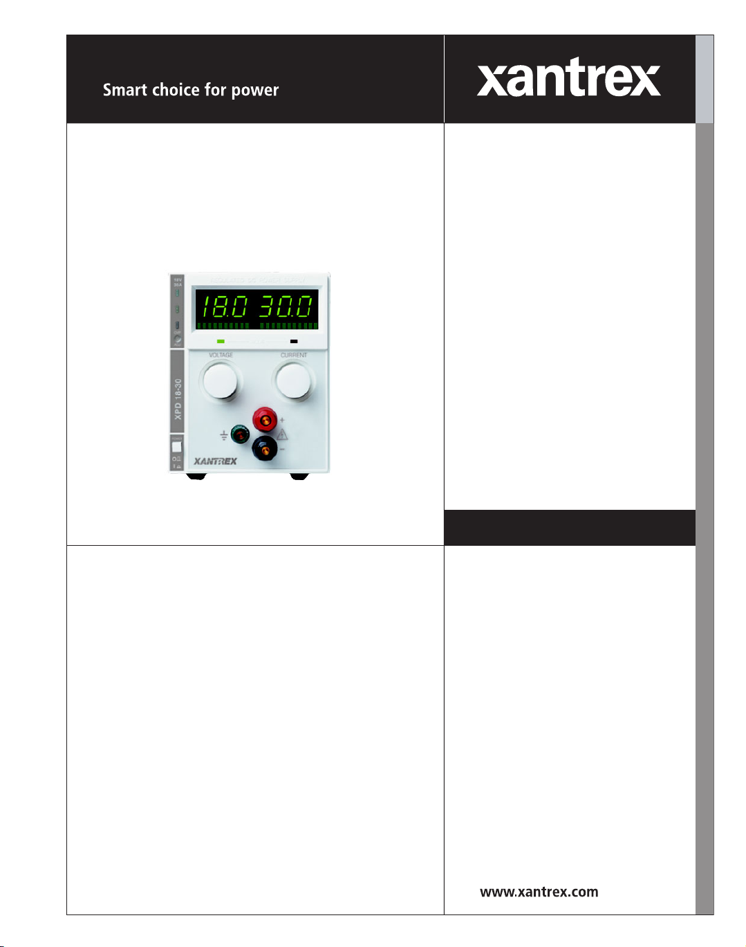
XPD 500 Watt Series
Programmable DC
Power Supply
XPD 7.5-67
XPD 18-30
XPD 33-16
XPD 60-9
XPD 120-4.5
Operating Manual
Page 2

Page 3

Operating Manual for
XPD Series
Programmable DC
Power Supply
Page 4

Limited
Warranty
What does this warranty cover and how long does it last?
This Limited Warranty is provided by Xantrex Technology, Inc. (“Xantrex”) and
covers defects in workmanship and materials in your XPD 500 Watt Series DC
Power Supply. This warranty lasts for a Warranty Period of 5 years from the date of
purchase at point of sale to you, the original end user customer.
What will Xantrex do?
Xantrex will, at its option, repair or replace the defective product free of charge,
provided that you notify Xantrex of the product defect within the Warranty Period,
and provided that Xantrex through inspection establishes the existence of such a
defect and that it is covered by this Limited Warranty.
Xantrex will, at its option, use new and/or reconditioned parts in performing
warranty repair and building replacement products. Xantrex reserves the right to use
parts or products of original or improved design in the repair or replacement. If
Xantrex repairs or replaces a product, its warranty continues for the remaining
portion of the original Warranty Period or 90 days from the date of the return
shipment to the customer, whichever is greater. All replaced products and all parts
removed from repaired products become the property of Xantrex.
Xantrex covers both parts and labor necessary to repair the product, and return
shipment to the customer via a Xantrex-selected non-expedited surface freight
within the contiguous United States and Canada. Alaska and Hawaii are excluded.
Contact Xantrex Customer Service for details on freight policy for return shipments
outside of the contiguous United States and Canada.
How do you get service?
If your product requires troubleshooting or warranty service, contact your merchant.
If you are unable to contact your merchant, or the merchant is unable to provide
service, contact Xantrex directly at:
Phone: 604 422 8595
Toll Free North America: 1 800 667 8422
Fax: 604 421 3056
Email: info@xantrex.com
ii Operating Manual for XPD Series Power Supply
Page 5

Direct returns may be performed according to the Xantrex Return Material
Authorization Policy described in your product manual. For some products, Xantrex
maintains a network of regional Authorized Service Centers. Call Xantrex or check
our website to see if your product can be repaired at one of these facilities.
In any warranty claim, dated proof of purchase must accompany the product and the
product must not have been disassembled or modified without prior written
authorization by Xantrex.
Proof of purchase may be in any one of the following forms:
• The dated purchase receipt from the original purchase of the product at point of
sale to the end user, or
• The dated dealer invoice or purchase receipt showing original equipment
manufacturer (OEM) status, or
• The dated invoice or purchase receipt showing the product exchanged under
warranty
What does this warranty not cover?
This Limited Warranty does not cover normal wear and tear of the product or costs
related to the removal, installation, or troubleshooting of the customer’s electrical
systems. This warranty does not apply to and Xantrex will not be responsible for any
defect in or damage to:
a. the product if it has been misused, neglected, improperly installed, physically
damaged or altered, either internally or externally, or damaged from improper
use or use in an unsuitable environment;
b. the product if it has been subjected to fire, water, generalized corrosion,
biological infestations, and high input voltage from lightning strikes;
c. the product if repairs have been done to it other than by Xantrex or its authorized
service centers (hereafter “ASCs”);
d. the product if it is used as a component part of a product expressly warranted by
another manufacturer;
e. the product if its original identification (trade-mark, serial number) markings
have been defaced, altered, or removed.
Release A iii
Page 6

Disclaimer Product
THIS LIMITED WARRANTY IS THE SOLE AND EXCLUSIVE WARRANTY PROVIDED
BY XANTREX IN CONNECTION WITH YOUR XANTREX PRODUCT AND IS, WHERE
PERMITTED BY LAW, IN LIEU OF ALL OTHER WARRANTIES, CONDITIONS,
GUARANTEES, REPRESENTATIONS, OBLIGATIONS AND LIABILITIES, EXPRESS
OR IMPLIED, STATUTORY OR OTHERWISE IN CONNECTION WITH THE PRODUCT,
HOWEVER ARISING (WHETHER BY CONTRACT, TORT, NEGLIGENCE, PRINCIPLES
OF MANUFACTURER’S LIABILITY, OPERATION OF LAW, CONDUCT, STATEMENT
OR OTHERWISE), INCLUDING WITHOUT RESTRICTION ANY IMPLIED WARRANTY
OR CONDITION OF QUALITY, MERCHANTABILITY OR FITNESS FOR A
PARTICULAR PURPOSE. ANY IMPLIED WARRANTY OF MERCHANTABILITY OR
FITNESS FOR A PARTICULAR PURPOSE TO THE EXTENT REQUIRED UNDER
APPLICABLE LAW TO APPLY TO THE PRODUCT SHALL BE LIMITED IN DURATION
TO THE PERIOD STIPULATED UNDER THIS LIMITED WARRANTY.
IN NO EVENT WILL XANTREX BE LIABLE FOR ANY SPECIAL, DIRECT, INDIRECT,
INCIDENTAL OR CONSEQUENTIAL DAMAGES, LOSSES, COSTS OR EXPENSES
HOWEVER ARISING WHETHER IN CONTRACT OR TORT INCLUDING WITHOUT
RESTRICTION ANY ECONOMIC LOSSES OF ANY KIND, ANY LOSS OR DAMAGE TO
PROPERTY, ANY PERSONAL INJURY, ANY DAMAGE OR INJURY ARISING FROM OR
AS A RESULT OF MISUSE OR ABUSE, OR THE INCORRECT INSTALLATION,
INTEGRATION OR OPERATION OF THE PRODUCT.
Exclusions If this product is a consumer product, federal law does not allow an exclusion of
implied warranties. To the extent you are entitled to implied warranties under federal
law, to the extent permitted by applicable law they are limited to the duration of this
Limited Warranty. Some states and provinces do not allow limitations or exclusions
on implied warranties or on the duration of an implied warranty or on the limitation
or exclusion of incidental or consequential damages, so the above limitation(s) or
exclusion(s) may not apply to you. This Limited Warranty gives you specific legal
rights. You may have other rights which may vary from state to state or province to
province.
iv Operating Manual for XPD Series Power Supply
Page 7

Information WITHOUT LIMITING THE GENERALITY OF THE FOREGOING, UNLESS
SPECIFICALLY AGREED TO BY IT IN WRITING, XANTREX
a. MAKES NO WARRANTY AS TO THE ACCURACY, SUFFICIENCY OR SUITABILITY
OF ANY TECHNICAL OR OTHER INFORMATION PROVIDED IN MANUALS OR
OTHER DOCUMENTATION PROVIDED BY IT IN CONNECTION WITH THE
PRODUCT; AND
b. ASSUMES NO RESPONSIBILITY OR LIABILITY FOR LOSSES, DAMAGES,
COSTS OR EXPENSES, WHETHER SPECIAL, DIRECT, INDIRECT,
CONSEQUENTIAL OR INCIDENTAL, WHICH MIGHT ARISE OUT OF THE USE OF
SUCH INFORMATION.
THE USE OF ANY SUCH INFORMATION WILL BE ENTIRELY AT THE USER’S RISK.
WARNING:
Limitations
on Use
Please refer to your product user manual for limitations on uses of the product.
Specifically, please note that this power supply is not intended for use in connection
with life support systems and Xantrex makes no warranty or representation in
connection with any use of the product for such purposes.
Xantrex Technology, Inc.
8999 Nelson Way
Burnaby, British Columbia
Canada V5A 4B5
Information
About Your
Power
Supply
Please record the following information when you first open your Power Supply
package:
Model Number ______________________________________________
Serial Number ______________________________________________
Purchased From ______________________________________________
Purchase Date ______________________________________________
Release Release A (2003-06)
Copyright © 2002 Xantrex Technology Inc. All rights reserved.
Printed in Canada
Release A v
Page 8
Warnings
!
!
!
and
Cautions
Power
Supply
Safety
Warnings and cautions are defined and formatted in this manual as shown below.
WARNING
Describes a potential hazard which could result in injury or death, or, a procedure
which, if not performed correctly, could result in injury or death.
CAUTION
Describes a procedure which, if not performed correctly, could result in damage
to data, equipment, or systems.
WARNING—High Energy and High Voltage
Exercise caution when using and calibrating a power supply. High energy levels
can be stored at the output voltage terminals on a power supply in normal
operation. In addition, potentially lethal voltages exist in the power circuit and on
the output and sense connectors of a power supply with a rated output greater
than 40 V. Filter capacitors store potentially dangerous energy for some time after
power is removed.
CAUTION
Operate the power supply in an environment free of flammable gases or fumes. To
ensure that the power supply’s safety features are not compromised, use the
power supply as specified in this manual and do not substitute parts or make any
unauthorized modifications. Contact the service technician for service and repair
help. Repairs must be made by experienced service technicians only.
CAUTION
For Use as a Battery Charger
When you are using any of these power supplies for battery charging applications,
it is essential to provide an appropriately sized fuse or circuit breaker in series
between the power supply output and the battery.
Installation of a protector (fuse or DC circuit breaker) rated for about 115% of the
maximum current rating of the power supply and designed specifically to interrupt
the DC voltage of the battery, will provide adequate reverse polarity current
protection. Where several power supplies are in parallel, it is best to fuse each one,
rather than one large fuse for all.
vi Operating Manual for XPD Series Power Supply
Page 9

About This Manual
This Operating Manual contains operating information for the XPD Series of
high-performance, switching, laboratory power supplies, available in several voltage
models at 500 watts. It provides information on features and specifications,
installation procedures, and basic functions testing, as well as operating procedures
for using both front panel control and remote analog programming functions.
Who Should Use This Manual
This manual is designed for the user who is familiar with basic electrical theory,
especially as they apply to the operation of power supplies. This implies a
recognition of Constant Voltage and Constant Current operating modes and the
control of input and output power, as well as the observance of safe techniques while
making supply or pin connections and any changes in switch settings.
Main Sections
Section 1 Features and Specifications Describes the power supply and lists
its features and specifications.
Section 2 Installation Goes through basic setup procedures. Describes
inspection, cleaning, shipping, and storage procedures. Includes AC input
connection, basic functions testing, and load and sense lines connections.
Section 3 Local Operation Provides procedures for local (front panel)
operation. Includes procedures for using over voltage protection, shutdown function,
multiple supplies, and over temperature protection.
Section 4 Remote Operation Covers remote analog programming operation
and remote monitoring of output voltage and current.
Manual Revisions
The current release of this manual is listed below. Updates may be issued as an
addendum.
Release A (2003-06)
Release A vii
Page 10

About This Manual
Power Supply Safety Markings
Alternating Current Off (Supply)
Earth (Ground) Terminal On (Supply)
Protective Conductor Terminal
Caution (Check manual for
additional information.)
viii Operating Manual for XPD Series Power Supply
Page 11

Contents
About This Manual . . . . . . . . . . . . . . . . . . . . . . . . . . . . . . . . . . . . . . . . . . . . . . . . . . . vii
Section 1.
Features and
Specifications
Section 2.
Installation
Description . . . . . . . . . . . . . . . . . . . . . . . . . . . . . . . . . . . . . . . . . . . . . . . . . . . . . . . . . 11
Features and Options . . . . . . . . . . . . . . . . . . . . . . . . . . . . . . . . . . . . . . . . . . . . . . . . . 11
Front Panel Controls. . . . . . . . . . . . . . . . . . . . . . . . . . . . . . . . . . . . . . . . . . . . . . . . . . 12
Rear Panel Connectors . . . . . . . . . . . . . . . . . . . . . . . . . . . . . . . . . . . . . . . . . . . . . . .13
Output Connectors . . . . . . . . . . . . . . . . . . . . . . . . . . . . . . . . . . . . . . . . . . . . . . . 14
Rear Panel J210 Connector. . . . . . . . . . . . . . . . . . . . . . . . . . . . . . . . . . . . . . . . 15
Making J210 Connections . . . . . . . . . . . . . . . . . . . . . . . . . . . . . . . . . . . . . . . . . 17
Wiring. . . . . . . . . . . . . . . . . . . . . . . . . . . . . . . . . . . . . . . . . . . . . . . . . . . . . . . . . 17
Electrical Specifications . . . . . . . . . . . . . . . . . . . . . . . . . . . . . . . . . . . . . . . . . . . . . . . 18
Additional Specifications. . . . . . . . . . . . . . . . . . . . . . . . . . . . . . . . . . . . . . . . . . . . . . . 19
Input Conditions . . . . . . . . . . . . . . . . . . . . . . . . . . . . . . . . . . . . . . . . . . . . . . . . . . . . .19
Additional Characteristics . . . . . . . . . . . . . . . . . . . . . . . . . . . . . . . . . . . . . . . . . . . . . . 20
Remote Programming and Monitoring . . . . . . . . . . . . . . . . . . . . . . . . . . . . . . . . . . . . 20
Environmental Specifications . . . . . . . . . . . . . . . . . . . . . . . . . . . . . . . . . . . . . . . . . . . 21
Mechanical Specifications . . . . . . . . . . . . . . . . . . . . . . . . . . . . . . . . . . . . . . . . . . . . . 21
Introduction. . . . . . . . . . . . . . . . . . . . . . . . . . . . . . . . . . . . . . . . . . . . . . . . . . . . . . . . . 23
Basic Setup Procedure . . . . . . . . . . . . . . . . . . . . . . . . . . . . . . . . . . . . . . . . . . . . . . . . 23
Inspection, Cleaning, and Packaging . . . . . . . . . . . . . . . . . . . . . . . . . . . . . . . . . . . . . 24
Initial Inspection . . . . . . . . . . . . . . . . . . . . . . . . . . . . . . . . . . . . . . . . . . . . . . . . . 24
Periodic Cleaning. . . . . . . . . . . . . . . . . . . . . . . . . . . . . . . . . . . . . . . . . . . . . . . . 24
Returning Power Supplies to the Manufacturer . . . . . . . . . . . . . . . . . . . . . . . . . . . . . 25
Return Material Authorization Policy . . . . . . . . . . . . . . . . . . . . . . . . . . . . . . . . . 25
Packaging for Shipping or Storage . . . . . . . . . . . . . . . . . . . . . . . . . . . . . . . . . . 26
Location, Mounting, and Ventilation . . . . . . . . . . . . . . . . . . . . . . . . . . . . . . . . . . . . . . 27
Rack Mounting . . . . . . . . . . . . . . . . . . . . . . . . . . . . . . . . . . . . . . . . . . . . . . . . . . 27
Ventilation . . . . . . . . . . . . . . . . . . . . . . . . . . . . . . . . . . . . . . . . . . . . . . . . . . . . . 27
AC Input Power Connection . . . . . . . . . . . . . . . . . . . . . . . . . . . . . . . . . . . . . . . . . . . . 28
AC Input Connector . . . . . . . . . . . . . . . . . . . . . . . . . . . . . . . . . . . . . . . . . . . . . .28
AC Input Cord . . . . . . . . . . . . . . . . . . . . . . . . . . . . . . . . . . . . . . . . . . . . . . . . . . 28
Functional Tests . . . . . . . . . . . . . . . . . . . . . . . . . . . . . . . . . . . . . . . . . . . . . . . . . . . . . 29
Power-on Check. . . . . . . . . . . . . . . . . . . . . . . . . . . . . . . . . . . . . . . . . . . . . . . . . 29
Voltage Mode Operation Check. . . . . . . . . . . . . . . . . . . . . . . . . . . . . . . . . . . . . 29
Current Mode Operation Check . . . . . . . . . . . . . . . . . . . . . . . . . . . . . . . . . . . . .29
Load Connection. . . . . . . . . . . . . . . . . . . . . . . . . . . . . . . . . . . . . . . . . . . . . . . . . . . . . 30
Load Wiring . . . . . . . . . . . . . . . . . . . . . . . . . . . . . . . . . . . . . . . . . . . . . . . . . . . . 30
Making Load Connections . . . . . . . . . . . . . . . . . . . . . . . . . . . . . . . . . . . . . . . . .31
Inductive Loads . . . . . . . . . . . . . . . . . . . . . . . . . . . . . . . . . . . . . . . . . . . . . . . . . 32
Connecting Multiple Loads. . . . . . . . . . . . . . . . . . . . . . . . . . . . . . . . . . . . . . . . . 32
Remote Sensing . . . . . . . . . . . . . . . . . . . . . . . . . . . . . . . . . . . . . . . . . . . . . . . . . . . . . 33
Sense Wiring . . . . . . . . . . . . . . . . . . . . . . . . . . . . . . . . . . . . . . . . . . . . . . . . . . .34
Release A ix
Page 12

Section 3.
Local
Operation
Introduction . . . . . . . . . . . . . . . . . . . . . . . . . . . . . . . . . . . . . . . . . . . . . . . . . . . . . . . . 35
Standard Operation . . . . . . . . . . . . . . . . . . . . . . . . . . . . . . . . . . . . . . . . . . . . . . . . . . 35
Operating Modes and Automatic Crossover . . . . . . . . . . . . . . . . . . . . . . . . . . . 35
Constant Voltage Mode Operation . . . . . . . . . . . . . . . . . . . . . . . . . . . . . . . . . . 36
Constant Current Mode Operation . . . . . . . . . . . . . . . . . . . . . . . . . . . . . . . . . . 36
Setting the Current Limit . . . . . . . . . . . . . . . . . . . . . . . . . . . . . . . . . . . . . . . . . . 36
Setting the Supply to Operate in CI Mode. . . . . . . . . . . . . . . . . . . . . . . . . . . . . 37
Automatic Mode Crossover. . . . . . . . . . . . . . . . . . . . . . . . . . . . . . . . . . . . . . . . 37
Shipped Configuration (Local Control Mode) . . . . . . . . . . . . . . . . . . . . . . . . . . . . . . . 37
Using Over Voltage Protection (OVP) . . . . . . . . . . . . . . . . . . . . . . . . . . . . . . . . . . . . 38
Defining the OVP Setpoint . . . . . . . . . . . . . . . . . . . . . . . . . . . . . . . . . . . . . . . . 38
OVP Circuit Check . . . . . . . . . . . . . . . . . . . . . . . . . . . . . . . . . . . . . . . . . . . . . . 38
Using the Shutdown Function . . . . . . . . . . . . . . . . . . . . . . . . . . . . . . . . . . . . . . . . . . 39
Controlling Shutdown Function via J210 Connector . . . . . . . . . . . . . . . . . . . . . 39
Master-Slave Tracking. . . . . . . . . . . . . . . . . . . . . . . . . . . . . . . . . . . . . . . . . . . . . . . . 39
Using Multiple Supplies . . . . . . . . . . . . . . . . . . . . . . . . . . . . . . . . . . . . . . . . . . . . . . . 40
User Diagnostics . . . . . . . . . . . . . . . . . . . . . . . . . . . . . . . . . . . . . . . . . . . . . . . . . . . . 45
Emergency Shutdown . . . . . . . . . . . . . . . . . . . . . . . . . . . . . . . . . . . . . . . . . . . . 45
Unusual or Erratic Operation. . . . . . . . . . . . . . . . . . . . . . . . . . . . . . . . . . . . . . . 45
Trouble Shooting for Operators. . . . . . . . . . . . . . . . . . . . . . . . . . . . . . . . . . . . . 45
Section 4.
Remote
Operation
Introduction . . . . . . . . . . . . . . . . . . . . . . . . . . . . . . . . . . . . . . . . . . . . . . . . . . . . . . . . 49
Remote Digital Programming . . . . . . . . . . . . . . . . . . . . . . . . . . . . . . . . . . . . . . 49
Remote Analog Programming of Output Voltage and Current Limit . . . . . . . . . . . . . 49
Remote Programming Options . . . . . . . . . . . . . . . . . . . . . . . . . . . . . . . . . . . . . 50
Programming Output Voltage with a 0-10 Vdc Voltage Source . . . . . . . . . . . . 50
Programming Output Current with a 0-10 Vdc Voltage Source. . . . . . . . . . . . . 50
Readback and Status Indicators . . . . . . . . . . . . . . . . . . . . . . . . . . . . . . . . . . . . . . . . 50
Voltage and Current Readback. . . . . . . . . . . . . . . . . . . . . . . . . . . . . . . . . . . . . 50
Status Flags. . . . . . . . . . . . . . . . . . . . . . . . . . . . . . . . . . . . . . . . . . . . . . . . . . . . . . . . 51
x Operating Manual for XPD Series Power Supply
Page 13

Section 1. Features and Specifications
Description
The XPD Series of DC power supplies provides stable, variable output voltage and
current for a broad range of development and system requirements. The units use
high-frequency soft-switching technology to achieve high power density and retain
a small package size. They feature a built-in analog programming interface, with
optional RS-232 and IEEE-488 controlled programming, making this series the first
choice in flexible power system design. See Table 1.1 for the list of available models.
Table 1.1 500 Watt Series Models
Model Output Voltage Output Current
7.5-67 0-7.5 V 0-67 A
18-30 0-18 V 0-30 A
33-16 0-33 V 0-16 A
60-9 0-60 V 0-9 A
120-4.5 0-120 V 0-4.5 A
Features and Options
• The power supply delivers simultaneous digital displays for both voltage and
current, and bar graph displays for monitoring transient changes, which gives the
user the benefit of continuous, up-to-date information.
• Active Power Factor Correction (PFC) delivers lower input current and input
current harmonics.
• Ten-turn voltage and current controls permits high resolution setting of the
output.
• The automatic crossover system allows the power supply to automatically
switch operating modes between current or voltage mode.
• Multiple units can be connected in parallel or series to produce greater diversity
or for use in high precision applications.
• Short-circuit-proof power outlets give greater operating safety.
• A built-in Analog Programming (APG) Interface provides analog signal control
of voltage and current, overvoltage protection (OVP), master/slave output
tracking, and remote ENABLE/DISABLE for safety and precision.
Release A 11
Page 14
Section 1. Features and Specifications
Front Panel Controls
• This unit may be equipped with an optional internal GPIB or RS-232 control for
remote digital programming and readback.
• Remote output sensing provides load cable compensation up to 5 V/line
(3 V/line for 7.5 V model).
• A rack mount kit (Option RM) is also available for this product.
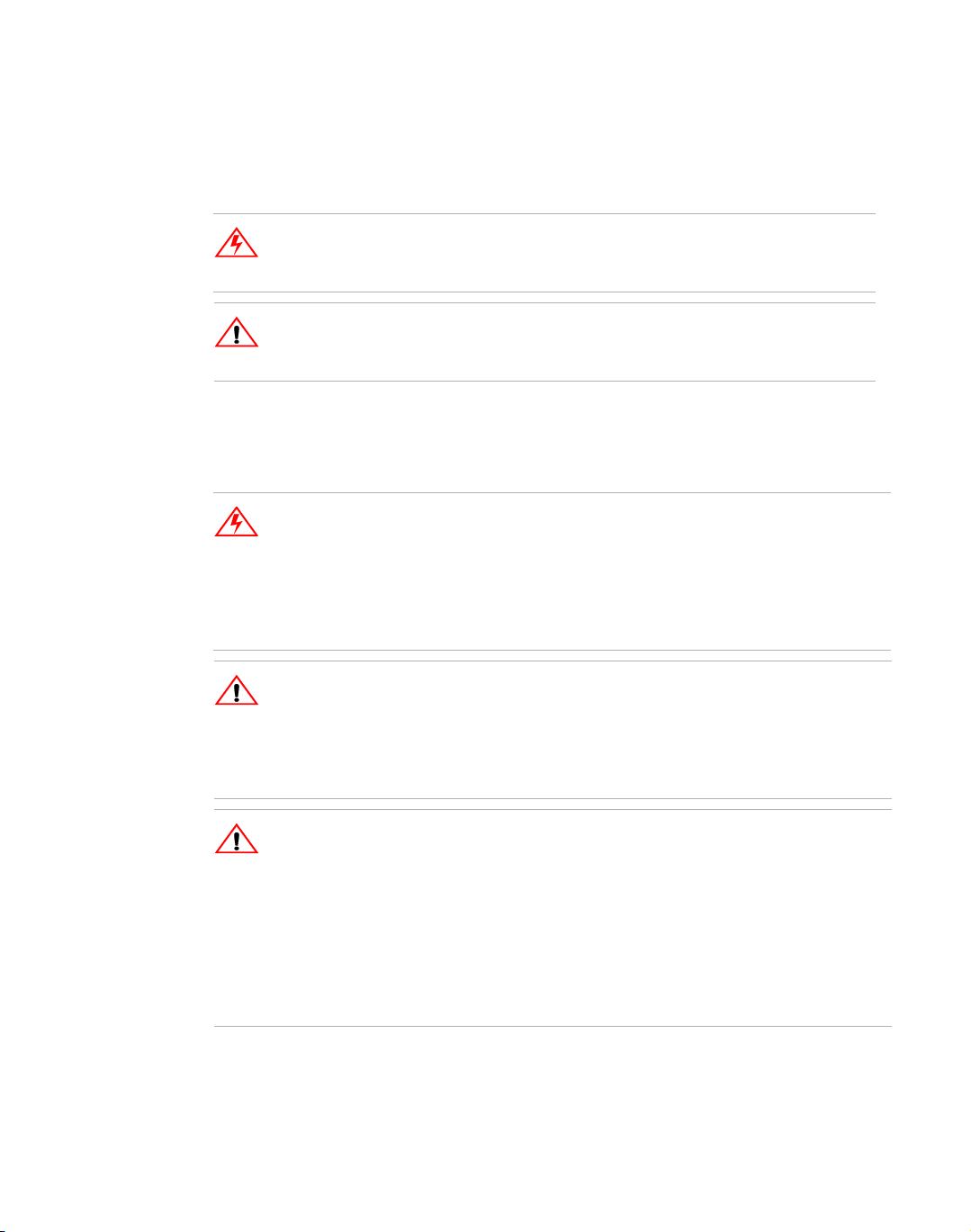
Front Panel Controls
See Figure 1.1 to review the displays, LEDs, indicators, and controls located on the
power supply’s front panel. Check the following sections for additional descriptions
for front panel controls and functions.
• “Mechanical Specifications” on page 21
• “Functional Tests” on page 29
• “Standard Operation” on page 35l
SQR: Service Request.
On M9B equipped units only
REM: Supply is under
Remote Control
S/D: Unit is in Stand By.
Supply output is disabled.
OVP ADJ: Single turn Over
Voltage Protection threshold
adjusting potentiometer
Voltage Mode Operation
Indicator (green LED)
10-turn Voltage Control Knob
AC Power Switch
Safety Ground Binding Post (green)
Figure 1.1 500 Watt Series Power Supply Front Panel
Digital Display of DC
Output (volts, amperes)
Analog Bar Graph Display
Current Mode Operation
Indicator (red LED)
10-turn Current Control Knob
Return (+) Output BInding Post
(red)
Return (-) Output BInding Post (black)
12 Operating Manual for XPD Series Power Supply
Page 15
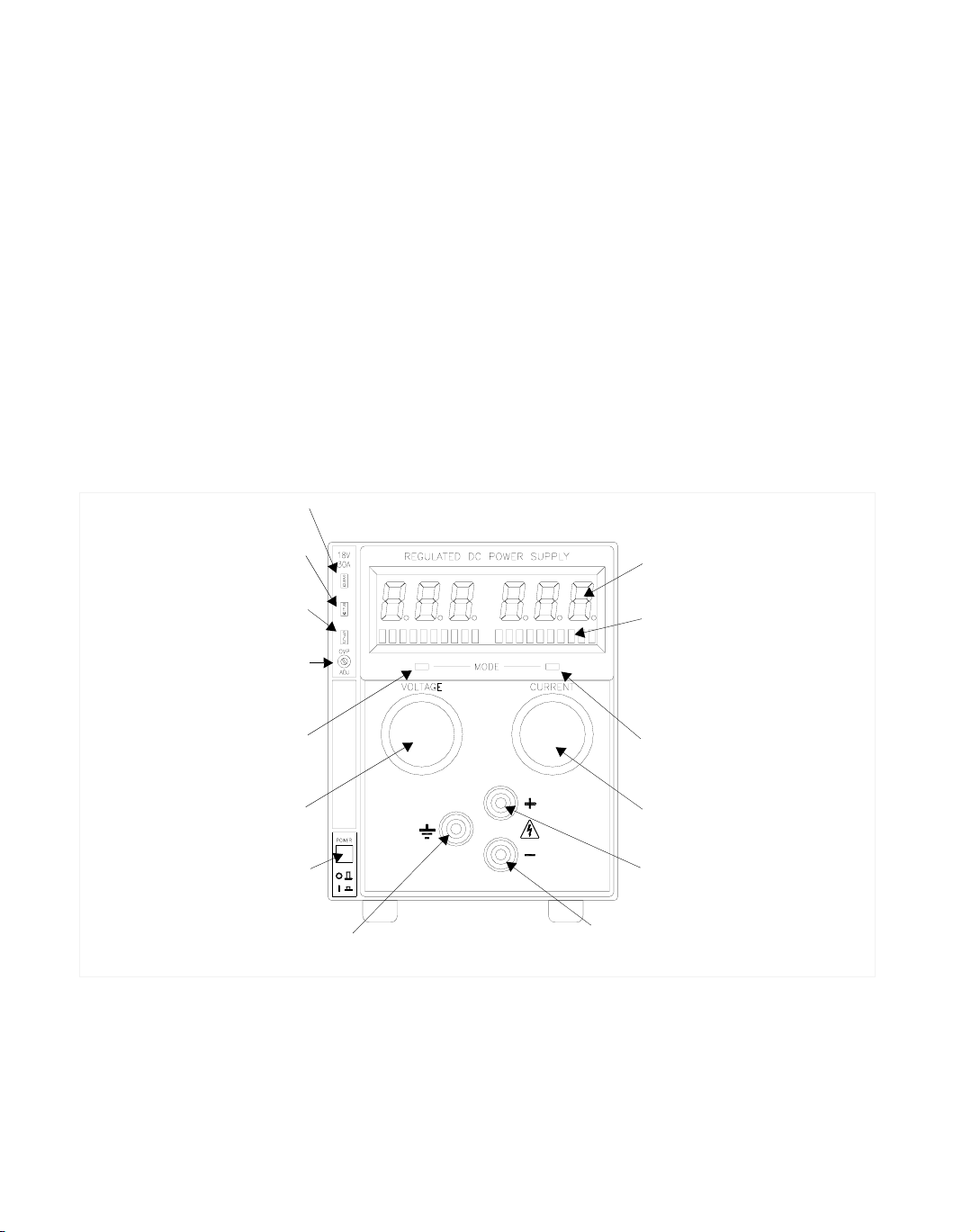
Rear Panel Connectors
Remote Sensing
Port: Remove
Default Jumpers to
use Remote Sensing
Programming and
Readback
Output Busbars
Section 1. Features and Specifications
Rear Panel Connectors
Blank Sub-Plate:
Replaced if Digital
Programming
Option is Installed
Fan Exhaust
Vents:
Do not obstruct
Analog
Busbar Cover
IEC 320 AC Input
Connector
Figure 1.2 500 Watt Power Supply Rear Panel (7.5 V and 18 V)
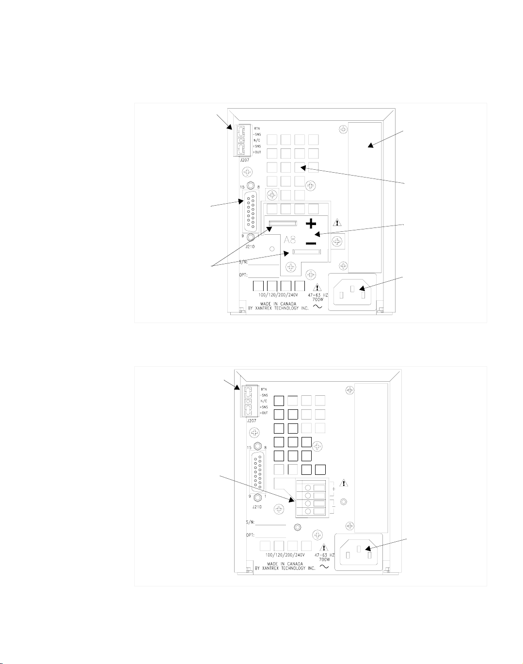
Remote Sensing
Port: Remove
Default Jumpers to
use Remote Sensing
DC Output
Connector:
33 V, 60 V and
120 V models
Figure 1.3 500 Watt Power Supply Rear Panel (33 V to 120 V)
IEC 320 AC Input
Connector
Release A 13
Page 16

Section 1. Features and Specifications
Rear Panel Connectors
Output
Connectors
Low Voltage Models Equipped with positive and negative busbars. The busbars
are offset to facilitate load cable connections.
WARNING
Disconnect the AC input before making any connections to the unit.
.
Figure 1.4 Output Busbars - note polarity markings
(Low Voltage Models)
High Voltage Models High voltage models are equipped with a 4-terminal output
block. The top two are positive terminals whereas the lower two are negative. Screw
clamps are used to secure load connections.
WARNING
Disconnect the AC input before making any connections. Lethal voltages may be
present at the output terminals for up to 15 seconds after the AC power has been
removed.
Figure 1.5 Output Terminal - note polarity markings
(High Voltage Models)
14 Operating Manual for XPD Series Power Supply
Page 17
Section 1. Features and Specifications
Rear Panel Connectors
Rear Panel
J210
Connector
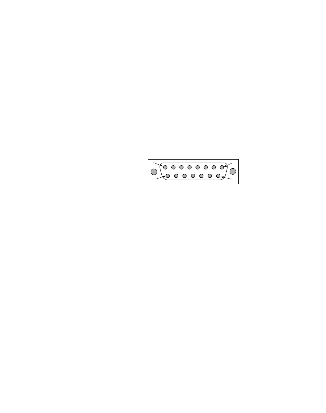
The J210 Analog Interface connector is a 15-pin female DSUB connector located on
the rear panel. See Figure 1.6. Use the J210 programming, monitoring, and
shutdown 15 pin DSUB connector for remote programming and monitoring
functions. See Figure 1.2 for the location of the J210 connector at the rear panel. We
recommend that you mate the J210 connector with a 15-pin male connector, such as
a Tyco 747908-2 or equivalent.
The J210 connector provides access to the following functions:
• Remote programming of both output voltage and current
• Calibrated readback signals for remote monitoring of output voltage and output
current
• Isolated remote shutdown function using a 5-15 V signal
See Figure 1.6 for a graphic presentation of the J210 connector and its pinouts.
8
15
Figure 1.6 Analog Interface Programming and Monitoring J210 Connector
See Table 1.2 for a list of the J210 connector pin numbers, their references, and
corresponding functions.
1
9
Release A 15
Page 18

Section 1. Features and Specifications
Rear Panel Connectors
Table 1.2 Rear Panel J210 Connector Pins and Functions
Pin Reference Name Function
J210-1 TTL S/D
RTN
J210-2 TTL S/D Shutdown Input (+) Input for shutdown signal.
J210-3 N/C No connection None.
J210-4 N/C No connection None.
J210-5 IPGM Output Current Limit
J210-6 VRMT
SELECT
J210-7 IRMT
SELECT
J210-8 AGND Auxiliary Ground Auxiliary ground.
J210-9 N/C No connection None.
J210-10 N/C No connection None.
J210-11 N/C No connection None.
J210-12 IMON Output current monitor Output for output current monitor
J210-13 PGM/MON
RTN
J210-14 VPGM Output Voltage
J210-15 VMON Output Voltage Monitor Output for output voltage monitor
1. The TTL shutdown circuit is isolated to 500 V from the power supply output and chassis.
2. Jumpering pins J210-6, J210-7, and J210-8 will select both remote output voltage
programming and remote output current limit programming.
Shutdown Signal Return
Return for shutdown signal
1
.
(−)
1
Input for current limit programming
Programming Input
Remote Output Voltage
Programming Select
Remote Output Current
Limit Programming
Select
signals from an analog device.
Selects remote output voltage
programming when to jumpered to
2
pin 8.
Selects remote output current limit
programming when jumpered to
2
pin 8.
signal.
Program/Monitor Return Return for voltage and current
program and monitor signals.
Input for voltage programming
Programming Input
signals from an analog device.
signal.
16 Operating Manual for XPD Series Power Supply
Page 19

Making J210
!
!
!
Connections
Wiring
Section 1. Features and Specifications
Rear Panel Connectors
CAUTION
Program/monitor signal and return are internally connected to the power
supply negative output. Do not attempt to bias these away from that
potential.
CAUTION
To maintain the isolation of the power supply output and prevent ground
loops, use an isolated (ungrounded) programming source when operating
the power supply via remote analog control at the J210 connector.
CAUTION
Before making connections from external circuits to the J210 connector, turn
the power supply OFF and wait until the front panel displays have gone out.
WARNING
There is a potential shock hazard at the output when using a power supply
with a rated output greater than 40 V. Use load wiring with a minimum
insulation rating equivalent to the maximum output voltage of the power
supply. For example, select TEW, 105
120 V, 4.5 A power supply.
°C, 300 V wiring for use with a
For most connectors and jumpers, use any suitable wire such as 16 to 24 AWG
stranded wire. For lowest noise performance, use shielded pair wiring of 16 to 24
AWG. Use the shortest leads possible. Ground the shield to pin 8 (auxiliary ground)
on the J210 connector or to the chassis via one of the J210 connector screws.
Release A 17
Page 20

Section 1. Features and Specifications
Electrical Specifications
Electrical Specifications
These specifications are warranted over a temperature range of 0 °C to 50 °C
with local sense. Above 50 °C, derate output linearly to zero at 70 °C. Nominal
line voltages are 100/120/200/230/240 Vac. Specifications and characteristics
refer to a single output model unless otherwise stated, and specifications apply
to either front or rear outputs unless noted.
Table 1.3 Electrical Specifications for 7.5 V to 120 V Models
Models 7.5-67 18-30 33-16 60-9 120-4.5
Output Ratings:
Output Voltage
Output Current
Output Power
Line regulation:
Voltage (0.01% of Vmax + 2 mV)
Current (0.01% of Imax + 1 mA)
Load Regulation:
Voltage (0.01% of Vmax + 2 mV)
Current (0.01% of Imax + 5 mA)
Meter Accuracy
Voltage (1% of Vmax + 1 count)
Current (1% of Imax + 1 count)
Output Noise (0-20 MHz):
Voltage (p-p) 50 mV 50 mV 75 mV 125 mV 180 mV
Output Ripple (0-100 kHz) (rms):
Voltage
Current
Drift (60 minutes):
Voltage (0.15% of Vmax)
Current (0.3% of Imax)
Drift (8 hours):
Voltage (0.03% of Vmax)
Current (0.05% of Imax)
Temperature Coefficient:
Voltage (0.015% of Vmax/º C
Current (0.02% of Imax/º C
OVP Adjustment Range:
Minimum (5% of Vmax)
Maximum (110% of Vmax)
Efficiency
2
3
4
5
6
7
8
0-7.5 V
0-67 A
502.5 W
2.8 mV
7.7 mV
2.8 mV
11.7 mA
0.2 V
0.8 A
5mV
250 mA
11.3 mV
201 mA
2.3 mV
34 mA
1.2 mV
13.4 mA
0.4 V
8.3 V
1
0-18 V
0-30 A
540 W
3.8 mV
4mV
3.8 mV
8mA
0.3 V
0.4 A
5mV
250 mA
27 mV
90 mA
5.4 mV
15 mA
2.7 mV
6mA
0.9 V
19.8 V
0-33 V
0-16 A
528 W
5.3 mV
2.6 mV
5.3 mV
6.6 mA
0.5 V
0.3 A
7.5 mV
150 mA
49.5 mV
48 mA
9.9 mV
8mA
5mV
3.2 mA
1.7 V
36.3 V
0-60 V
0-9 A
540 W
8mV
1.9 mV
8mV
5.9 mA
0.7 V
0.2 A
10 mV
150 mA
90 mV
27 mA
18 mV
4.5 mA
9mV
1.8 mA
3V
66 V
0-120 V
0-4.5 A
540 W
14 mV
1.5 mV
14 mV
5.5 mA
2.2 V
0.2 A
20 mV
75 mA
180 mV
13.5 mA
36 mV
2.3 mA
18 mV
0.9 mA
6V
132 V
81% 83% 85% 85% 84%
18 Operating Manual for XPD Series Power Supply
Page 21

Section 1. Features and Specifications
Additional Specifications
1. Front output current limited to 30 A maximum.
2. For input voltage variation over the AC input voltage range, with constant rated load.
3. For 0 to 100% load variation, with constant nominal line voltage (rear output only).
4. Current mode noise is measured from 10% to 100% of rated output voltage, full current, resistive load.
5. Maximum drift over 60 minutes with constant line, load, and temperature, after power on.
6. Maximum drift over 8 hours with constant line, load, and temperature, after 60-minute warm-up.
7. Change in output per ° C change in ambient temperature, with constant line and load.
8. Typical efficiency is measured at 120 V and full output power.
Additional Specifications
Rise Time (No load, full load) 50 ms
Fall Time (Full load) 50 ms
Fall Time (No load) 400 ms
Voltage Mode Transient Response 1 ms
Time delay from power on until output stable 3 s maximum
Input Conditions
Rated AC Input Voltage 100/120/200/230/240 Vac, universal input
Maximum AC Input Power 700 W
Operational AC Input Voltage Range 85 to 264 Vac; power factor corrected
Maximum Input Current 7 A maximum at 100 Vac, 6 A maximum at
120 Vac, 3 A maximum at 220 Vac
Input Frequency Range 47 to 63 Hz
Power Factor 0.98 minimum for full load at nominal
voltage
Input Harmonic Distortion Current harmonics meet IEC 1000-3-2
Release A 19
Page 22

Section 1. Features and Specifications
Additional Characteristics
Additional Characteristics
Over Temperature Protection (OTP) Unit latches off when T > rated maximum.
OVP Control Adjustable on front panel single turn control.
Switching Frequency 125 kHz (250 kHz output ripple)
Output Hold-up Time 10 ms @120 Vac input
Insulation Resistance Input to chassis: >30 M ohm, with 500 Vdc
Isolation Voltage Input to output: 1350 Vac
Remote Programming and Monitoring
Auto restart when cool
110% setting 5% of rated output
Output to chassis: >20 M ohm, with
1000 Vdc
Remote S/D and Interlock
1
5–15 V signal or TTL-compatible output,
selectable logic. TTL input impedance: 2 k
(in series with one diode drop)
Remote Analog Programming (Full
Scale Input)
Voltage and current programming inputs
(source must be floating): 0-10 V voltage
sources.
Input impedance (V and I): 20 k
Remote Monitoring Output voltage and current: 0-10 V
Output impedance (V and I): approximately
221 ohm; output short circuit current:
approximately 20 mA (load must be floating)
Remote Programming and Monitoring
1% of full scale output for the default range
Accuracy
Maximum Remote Sense Line Drop
Compensation
7.5 V model: 3 V/line;
18-120 V models: 5 V/line
2
2
Optional Digital Control RS-232, GPIB interfaces
1. Isolated from power supply output and chassis to 500 V.
2. Line drop must be deduced from supply maximum output.
20 Operating Manual for XPD Series Power Supply
Page 23

Environmental Specifications
Operating Temperature Range 0 to 50 °C
Storage Temperature Range -40 to 85 °C
Humidity Range Up to 95% RH non-condensing
Operating Altitude Maximum 6,500 feet (2,000 m)
Storage Altitude Up to 50,000 feet (15 000 m)
Installation Category
Pollution Degree 2
Mechanical Specifications
Section 1. Features and Specifications
Environmental Specifications
Derate maximum operating temperature by
1 °C per 1,000 feet (300 m) for operation
between 5,000 feet (1500 m) and 6,500 feet
(2,000 m)
II
Front Panel Voltage and Current
Control
Front Panel Voltage Control Resolution 0.02% of maximum voltage
Front Panel Current Control Resolution 0.02% of maximum current
Front Panel Voltage and Current
Meters
AC Input Connector Type IEC 320 connector, appropriate power cord
Input Fuses Non-user accessible, both lines fused.
Output Connector Front panel: 5-way binding posts maximum
Sense Connector 5 terminal wire clamp connector
Analog Programming Connector 15-pin female DSUB connector
Chassis Ground Front panel binding post; chassis is
Cooling Fan cooled. Variable speed fan. Air flows
10-turn voltage and current potentiometers
3-digit green numeric LED displays. For
meter accuracy, see Table 1.3, on page 18
provided for destination country
current limit 30 A
Rear panel: 7.5–18 V models: bus bars with
0.3” holes. 33–120 V models: wire clamp
connectors
grounded through power cord
from front to rear, with vents on top, bottom,
and sides
Release A 21
Page 24

Section 1. Features and Specifications
Mechanical Specifications
Mounting Optional 19 in. (483 mm) rack mount kit
Maximum Dimensions
(single output)
Weight Single output: 9.0lb. (4.1 kg)
Approvals
Accessories Rack mount kit
Options GPIB, RS-232 interfaces
(mounts 4 units).
Free standing:
Height: 5.55 in. (140 mm)
Width: 4.24 in (108 mm)
Mounted:
Height: 5.25 in.(133 mm) (3 U).
Width: 1/4 rack (4 per 19 in. rack)
Depth: 13 in. (330 mm) (not including front
panel controls and front and back output
terminals)
CSA certified to UL 3101-1, CSA C22.2 No.
1010-1, and 1010-1B
FCC Part 15B and Industry Canada Class A
CE Marked for Low Voltage Directive and
EMC Directive (Class A emissions)
22 Operating Manual for XPD Series Power Supply
Page 25

Section 2. Installation
Introduction
This section provides recommendations and procedures for inspecting, installing,
and testing the power supply.
Basic Setup Procedure
See Table 2.1 for a summary of the basic setup procedure and a view of the
subsections in this section. Use this procedure as a quick reference if you are
unfamiliar with the installation requirements for the power supply. Each step in the
procedure refers to subsequent sections which contain more details. Follow each step
in the sequence given.
Table 2.1 Basic Setup Procedure
Step # Description Action Reference
1 Inspection Perform an initial physical
inspection of the power
supply.
2 Installation Install the supply (bench or
rack mount). Ensure
adequate ventilation.
3 Input Power Connect AC input power. “AC Input Power Connection”
4 Test Perform functional tests for
voltage mode operation,
current mode operation,
and front panel controls.
5 Load Connect the load. “Load Connection” on page 30
6 Sensing Connect sensing lines. “Remote Sensing” on page 33
“Inspection, Cleaning, and
Packaging” on page 24
“Location, Mounting, and
Ventilation” on page 27
on page 28
“Functional Tests” on page 29
Release A 23
Page 26

Section 2. Installation
Inspection, Cleaning, and Packaging
Inspection, Cleaning, and Packaging
Initial
Inspection
Periodic
Cleaning
When you first receive your unit, perform a quick physical check.
1. Inspect the unit for scratches and cracks in the chassis and front panel, and for
broken switches, connectors, and displays.
2. If you see external damage or suspect internal damage, have a service technician
check the unit before attempting to use it. If the unit is damaged, save all packing
materials and notify the carrier immediately. See packing instructions in
“Returning Power Supplies to the Manufacturer” on page 25.
3. Ensure that the packing box contains the 7.5' (2.5 m) power cord.
No routine servicing of the power supply is required, except for periodic cleaning.
Whenever a unit is removed from operation, clean the metal surfaces with naptha or
an equivalent solvent and the front panel with a weak solution of soap and water. Use
low-pressure compressed air to blow dust from components on the printed circuit
boards.
24 Operating Manual for XPD Series Power Supply
Page 27

Returning Power Supplies to the Manufacturer
Section 2. Installation
Returning Power Supplies to the Manufacturer
Return
Material
Authorization
Policy
Before returning a product directly to Xantrex you must obtain a Return Material
Authorization (RMA) number and the correct factory “Ship To” address. Products
must also be shipped prepaid. Product shipments will be refused and returned at your
expense if they are unauthorized, returned without an RMA number clearly marked
on the outside of the shipping box, if they are shipped collect, or if they are shipped
to the wrong location.
When you contact Xantrex to obtain service, please have your operating manual
ready for reference and be prepared to supply:
• The serial number of your product
• Information about the installation and use of the unit
• Information about the failure and/or reason for the return
• A copy of your dated proof of purchase
When you ship:
1. Package the unit safely following the procedures on page 26, preferably using
the original box and packing materials. Please ensure that your product is
shipped fully insured in the original packaging or equivalent. This warranty will
not apply where the product is damaged due to improper packaging.
2. Include the following:
• The RMA number supplied by Xantrex Technology Inc clearly marked on
the outside of the box.
• A return address where the unit can be shipped. Post office boxes are not
acceptable.
• A contact telephone number where you can be reached during work hours
• A brief description of the problem
Ship the unit prepaid to the address provided by your Xantrex customer service
representative.
If you are returning a product from outside of the USA or Canada:
In addition to the above, you MUST include return freight funds and are fully
responsible for all documents, duties, tariffs, and deposits.
If you are returning a product to a Xantrex Authorized Service Center (ASC):
A Xantrex return material authorization (RMA) number is not required. However,
you must contact the ASC prior to returning the product or presenting the unit to
verify any return procedures that may apply to that particular facility.
Release A 25
Page 28

Section 2. Installation
Returning Power Supplies to the Manufacturer
Packaging for
Shipping or
Storage
Follow these instructions to prepare the unit for shipping or storage.
1. When returning the unit or sending it to the service center, attach a tag to the unit
stating its model number (available from the front panel label) and its serial
number (available from the rear panel label). Give the date of purchase and an
invoice number, if you have it, as well as a brief description of the problem.
2. For storage or shipping, repack the power supply in its original container. If the
original container is not available, seal the unit in a plastic bag and then pack it
in a 200 lb. (90 kg) test, corrugated cardboard carton large enough to allow 2
inches (5 cm) of cushioning material to surround the unit. Use a material such as
foam slabs or chips.
3. Label the carton as shown in Figure 2.1.
4. If shipping, mark the address of the service center and your return address on the carton.
5. If storing, stack no more than eight cartons high. Check the storage temperature
range and storage altitude specification in “Environmental Specifications” on
page 21.
POWER SUPPLY
Model Number: _______________________
Serial Number: _______________________
FRAGILE — ELECTRONIC EQUIPMENT
Figure 2.1 Shipping or Storage Carton Label
26 Operating Manual for XPD Series Power Supply
Page 29

Section 2. Installation
Location, Mounting, and Ventilation
Location, Mounting, and Ventilation
You may use the 500 watt power supply in rack-mounted or in benchtop
applications.
Rack
Mounting
WARNING
Ensure that any mounting screws do not penetrate more than 1/8 in. (3.0 mm)
into the bottom and/or back of the unit
The power supply is designed to fill 1/4 of a standard 19 in. (483 mm) equipment
rack.
Units can be combined with 300 watt and 60 watt series models for customer
applications. Contact the manufacturer about the RM (Rack Mount Kit) option.
Ventilation Whether operating the power supply in a rack or on a bench, allow cooling air to
reach the ventilation inlets on the bottom and sides of the unit. Ensure that
rack-mounted units have 1 U (1.75 in./44.5 mm) between units. Ventilation space at
the top and bottom, or sides of the power supply is essential for proper operation.
See “Environmental Specifications” on page 21, for the operating ambient
temperature range and the operating altitude specification.
Release A 27
Page 30
Section 2. Installation
!
AC Input Power Connection
AC Input Power Connection
WARNING
There is a potential shock hazard if the power supply chassis and cover are not
connected to an electrical ground via the safety ground in the AC input
connector. Ensure that the power supply is connected to a grounded AC outlet
with the recommended AC input cord configured for the available line voltage as
described in this section.
WARNING
Disconnect AC power from the unit before removing the cover. Even with the
front panel power switch in the OFF position, live line voltages are exposed
when the cover is removed. Repairs must be made only by experienced service
technicians.
CAUTION
When the power switch is turned on, the output voltage or current previously set
will be applied to loads
AC Input
Connector
The AC input connector is a standard IEC 15 A, 250 V male connector located on
the power supply’s rear panel. See Figure 1.2 500 Watt Power Supply Rear Panel
(7.5 V and 18 V), p. 13.
AC Input
Cord
WARNING
The AC input cord is the disconnect device for the power supply. The plug must
be readily identifiable by and accessible to the operator. The input cord must be
no longer than 9.85 feet (3 m).
The AC input cord that we provide is appropriate to the country of destination. If you
require a special cord, contact us.
28 Operating Manual for XPD Series Power Supply
Page 31

Functional Tests
These functional test procedures include power-on and front panel function checks
as well as voltage and current mode operation checks.
Section 2. Installation
Functional Tests
Power-on
Check
Voltage Mode
Operation
Check
Current Mode
Operation
Check
1. Ensure that the front panel power switch is in the extended (OFF) position and
the voltage and current controls are in their fully counter-clockwise positions.
2. Ensure that the AC line voltage is within operating range.
3. Plug the line cord into a grounded AC outlet.
4. Push the power switch to turn on the power supply.
After a short power-on delay, the display and the red current mode LED lights. The
meter reading remains at zero.
For more about standard operations, see “Standard Operation” on page 35.
1. Ensure that the front panel voltage and current control are turned fully
counter-clockwise.
2. Set the power switch to ON.
3. Rotate the current control one half-turn clockwise. Slowly rotate the voltage
control clockwise and observe the digital meter. Minimum control range should
be from zero to maximum rated output. Observe the bar graph meter to see that
it tracks as the voltage rises. Verify that the voltage mode indicator light is ON.
4. Set the power switch to OFF.
1. Ensure that the front panel power switch is set to OFF.
2. Rotate the voltage and current controls fully counter-clockwise.
3. Rotate the voltage control one half-turn clockwise.
4. Connect a short circuit across the output terminals. Use leads of sufficient
current carrying capacity.
5. Set the power switch to ON.
6. Rotate the current control slowly clockwise. The control range should be from
zero to the maximum rated output
1
. Also check that the current bar graph meter
follows the rise in current and that the current mode indicator light is ON.
7. Set the power switch to OFF.
1. On 7.5-67 model, front panel current is limited to 30 A. Short the rear busbar terminals to test the
full current range is required.
Release A 29
Page 32

Section 2. Installation
Load Connection
Load Connection
This section provides recommendations for load wires and covers single and
multiple load configurations.
Load Wiring Make load connections at the rear of the power supply at the positive (+) and
negative (−) terminals.
To select wiring for connecting the load to the power supply, consider the following
factors:
• insulation rating of the wire
• current carrying capacity of the wire
• maximum load wiring length for operation with sense lines
• noise and impedance effects of the load lines
Insulation Rating Use load wiring with a minimum insulation rating equivalent
to the maximum output voltage of the power supply.
Current Carrying Capacity As a minimum, load wiring must have a current
carrying capacity greater than the output rating of the power supply. This ensures that
the wiring will not be damaged, even if the load is shorted. Tabl e 2.2 shows the
maximum current rating, based on 450 A/cm
105 °C operation. Operating at the maximum current rating results in an
approximately 30 °C temperature rise for a wire operating in free air. Where load
wiring must operate in areas with elevated ambient temperatures or bundled with
other wiring, use larger gauges or wiring rated for higher temperatures.
2
, for various gauges of wire rated for
Table 2.2 Current Carrying Capacity for Load Wiring
Wire Size
(AWG)
20 2.5 6 61
18 4 4 97
16 6 2 155
14 10 1 192
12 16 1/0 247
10 21 2/0 303
836
30 Operating Manual for XPD Series Power Supply
Maximum Current
(A)
Wire Size
(AWG)
Maximum Current
(A)
Page 33

Section 2. Installation
!
Load Connection
WIRE GAUGE (AWG)
16
100
90
80
70
60
50
40
30
WIRE LENGTH (FEET)
20
10
1
2345678910
14
12
8
10
6
2030405060708090100
LOAD CURRENT (AMPS)
4
1 2/0
2 1/0
200
300
400
500
1000
Figure 2.2 Maximum Load Wire Length for 1 V Line Drop
Noise and Impedance Effects To minimize noise pickup or radiation, use
shielded pair wiring of shortest possible length for load wires. Connect the shield to
the power supply chassis. Where shielding is impossible or impractical, simply
twisting the wires together will offer some noise immunity.
Making Load Connections
WARNING
There is a shock hazard at the load when using a power supply with a rated
output greater than 40 V. To protect personnel against accidental contact with
hazardous voltages, ensure that the load, including connections, has no live
parts which are accessible. Also ensure that the insulation rating of the load
wiring and circuitry is greater than or equal to the maximum output voltage of the
power supply.
CAUTION
When making connections to the bus bars, ensure that each terminals’ mounting
hardware and wiring assembly are placed to avoid touching the other terminal
and shorting the power supply output. Heavy connecting cables must have some
form of strain relief to avoid loosening the connections or bending the bus bars.
Release A 31
Page 34

Section 2. Installation
Load Connection
Inductive
Loads
Connecting
Multiple
Loads
To prevent damage to the power supply from inductive kickback, connect a diode
across the output. The diode must be rated at least 20% greater than the supply’s
output voltage and have a current rating greater than or equal to the supply’s output
rating. Connect the cathode to the positive output and the anode to the return.
Where positive load transients such as back EMF from a motor may occur, connect
a transorb or a varistor across the output to protect the power supply. The breakdown
voltage rating for the transorb or varistor must be approximately 10% higher than the
rated supply output.
Proper connection of distributed loads is an important aspect of power supply use.
Two common methods of connection are the parallel power distribution method and
the radial power distribution method.
Radial Power Distribution Method To connect distributed loads, we
recommend that you use this method. With this method, you connect power to each
load individually from a single pair of terminals designated as the positive and
negative distribution terminals. This pair of terminals may be the power supply
output terminals, the load terminals, or a distinct set of terminals specially
established for distribution. In this scheme, there are no ground loops and the effect
of one load upon another is minimized.
Connect the remote sense leads to these terminals to compensate for losses and
minimize the effect of one load upon another. See “Remote Sensing” below for more
information about using remote sensing.
Parallel Power Distribution Method This distribution method involves
connecting leads from the power supply to one load, from that load to the next load,
and so on for each load in the system. The voltage at each load depends on the current
drawn by the other loads and DC ground loops are developed. Except for low-current
applications, we recommend that you do not use this method.
32 Operating Manual for XPD Series Power Supply
Page 35

Remote Sensing
Remote sensing permits you to shift the regulation point of the power supply from
the output terminals to the load or other distribution terminals. It compensates for
voltage losses of up to a total of 5 V in the power leads supplying the load (3 V on
7.5 V unit).
For best noise performance, use shielded pair wiring of 16 to 24 AWG for remote
sense lines.
Section 2. Installation
Remote Sensing
Remove default jumpers (Pins 1-2 and 4-5)
Connect sense lines as close to
load as possible or at point to be
regulated
In order to connect the sense wires, follow this procedure:
1. Using a small flat blade screwdriver, remove the two sense jumpers on the J207
connector.
2. Using the appropriate gauge shielded wire (see “Sense Wiring”), connect one
end to the load or point at which load is to be regulated.
3. Connect the positive sense line from the load to J207-4 (+SNS) and the return or
(-SNS).
Release A 33
Page 36

Section 2. Installation
Remote Sensing
To compensate for losses in power leads connected to the output, your power supply
provides sense connections beside the output terminals. With remote sense leads in
place, the supply regulates to the displayed voltage at the point where the sense lines
are connected to the output leads (provided the sum of these lead losses does not
exceed 5 V per line or 3.5 V per line for a 7.5 V unit). With the sense lines
disconnected, the supply regulates the voltage at the output terminals.
Do not operate the supply with sense lines connected to the load without also
connecting the load power leads to the output terminals. Avoid reversing positive and
negative lead connections.
Note Long load leads with large capacitance at the load and remote sensing can cause
voltage instability due to inductance of the load leads. Measures to reduce inductance
and/or capacitance (raising resonant frequency) or using local sense can be beneficial
in stabilizing the system.
Sense Wiring
WARNING
There is a potential shock hazard at the sense connectors when using a power
supply with a rated output greater than 40 V. Select wiring with a minimum
insulation rating equivalent to the maximum output voltage of the power supply
for use as local sense jumpers or for remote sense wires. Ensure that
connections at the load end are shielded to prevent contact with hazardous
voltages.
34 Operating Manual for XPD Series Power Supply
Page 37

Section 3. Local Operation
Introduction
Once you have installed the power supply, it is ready to operate in local control mode
(that is, operation at the unit’s front panel).
• See “Standard Operation” for a brief explanation of Constant Voltage and
Constant Current Mode operation.
• See “Using Over Voltage Protection (OVP)” on page 38, “Using the Shutdown
Function” on page 39, and “Using Multiple Supplies” on page 40 for information
on these topics.
• See “User Diagnostics” on page 45, for troubleshooting information for the
operator.
•Turn to Section 4. Remote Operation for descriptions of remote programming
options and remote monitoring of the supply.
Standard Operation
This power supply has two basic operating modes: Constant Voltage Mode and
Current Mode, and two control modes: Local Control Mode (default setting) and
Remote Programming Mode. Both operating modes are available regardless of
which control mode is used.
Operating
Modes and
Automatic
Crossover
The mode in which the power supply operates at any given time depends on the
combination of:
• output voltage setting V
• output current limit setting I
• resistance of the attached load R
SET
SET
L
See Figure 3.1 for a graphical representation of the relationships between these
variables.
Release A 35
Page 38

Section 3. Local Operation
Standard Operation
V
Output
Voltage
SET
Constant Voltage
Mode Region
V
SET
R
L
I
SET
Crossover Point
Constant Current
Mode Region
V
SET
R
L
I
SET
V
SET
R
L
I
SET
Where
Load Resistance
R
L
Output Voltage Setting
V
SET
Output Current Limit Setting
I
SET
Constant
Voltage Mode
Operation
Constant
Current Mode
Operation
0
0
Output
Current
I
SET
Figure 3.1 Operating Modes
Note The control circuits have been designed to allow you to set output voltage and
current up to 1.5% over the model-rated maximum values. The power supply will
operate within these extended ranges, but we cannot guarantee full performance to
specification.
The power supply will operate in constant voltage mode whenever the load current
I
L is less the current limit setting I
, or: IL < I
SET
(Note: IL = V
SET
/ RL). In
SET
constant voltage mode, the power supply maintains the output voltage at the selected
value (V
) while the load current IL varies with the load requirements.
SET
To use the power supply in Constant Voltage mode, either set the current limit to
maximum by turning the current control to its extreme clockwise position, or take
the precaution of setting a desired maximum current, then set the voltage control to
the desired voltage.
The power supply will operate in Constant Current mode whenever the load
resistance is low enough that the load current I
setting I
, or: IL>I
SET
output current at the selected value (I
. In constant current mode, the power supply maintains the
SET
) while the load voltage varies with the load
SET
is greater than the current limit
L
requirements.
Setting the
Current Limit
Set the Current Limit by following the steps below:
1. Connect a shorting lead across the output terminals.
2. Turn the voltage control a half-turn clockwise.
3. Set the desired maximum current limit by turning the current control slowly
clockwise to the desired level.
36 Operating Manual for XPD Series Power Supply
Page 39

Section 3. Local Operation
Shipped Configuration (Local Control Mode)
4. Disconnect the shorting lead from the output terminals. The power supply will
now automatically switch into current limiting mode (current regulation) as
soon as the preset current level is reached.
Setting the
Supply to
Operate in CI
Mode
To operate the supply in CI mode:
1. Set the current limit as described above.
2. Set the voltage control fully clockwise or to the compliance voltage of the
circuit.
As soon as the supply starts operating in current mode, the red current mode
LED will turn on.
Automatic
Mode
Crossover
The automatic crossover system allows the power supply to automatically switch
operating modes in response to changing load requirements. For example, if the load
current attempts to increase above the setting of the current adjust control, the unit
will switch automatically from Constant Voltage to Constant Current mode. If you
lower the load requirements, the supply will automatically return to Constant Voltage
mode.
Shipped Configuration (Local Control Mode)
The factory ships units already configured for local control (front panel) operation.
See Table for a summary of this configuration.
Table 3.1 Shipped Configuration (Local Control Mode)
Local Control Configuration Additional References
Use the front panel controls to adjust
output voltage and current limit
settings.
The OVP set point is adjusted at the
front panel to over 110% of rated
output voltage.
See Section for front panel operation.
See Section 4, page 49, for remote
analog programming procedures.
“Using Over Voltage Protection
See
(OVP)” on page 38
adjustment procedure.
, for the
Release A 37
Page 40

Section 3. Local Operation
Using Over Voltage Protection (OVP)
Using Over Voltage Protection (OVP)
The OVP circuit protects the load in the event of a remote programming error, an
incorrect voltage control adjustment, or a power supply failure. The protection
circuit monitors the output voltage at the output of the power supply and will shut
down the main power converter whenever a preset voltage limit is exceeded. Set the
preset voltage limit (also called the setpoint or trip level) using the
screwdriver-adjustable front panel OVP ADJ potentiometer, or via one of the
optional GPIB or RS-232 programming interfaces.
Defining the
OVP Setpoint
OVP Circuit
Check
1. Turn the power supply OFF.
2. Using a small, flat-blade screwdriver, turn the OVP ADJ potentiometer screw to
a fully clockwise position.
3. Turn the power supply ON. Set the output to the desired trip voltage.
4. Slowly turn the OVP ADJ potentiometer screw counter-clockwise until the red
OVP indicator lamp lights.
5. Push the power switch to OFF.
6. Turn the voltage control knob to minimum.
7. Push the power switch ON and increase the voltage to check that the power
supply shuts off the output at the set voltage.
8. Reset the OVP circuit after activation by removing the overvoltage condition
and turning the unit OFF and back ON, or, by momentarily activating the TTL
remote shutdown circuit. See “Using the Shutdown Function” on page 39, for
information about shutdown circuit operation.
1. Turn power supply ON.
2. Adjust voltage to maximum. Adjust the front panel OVP ADJUST
potentiometer counter-clockwise.
3. The OVP LED will light up and the output of the power supply will drop to near zero.
4. Rotate the front panel OVP ADJUST potentiometer fully clockwise.
5. Momentarily apply 5-15 V across J210 pins 1-2 (P1 -ve, P2 +ve) or cycle the AC
input power.
6. The power supply output will recover, indicating that the OVP circuit was reset
by momentarily activating the TTL S/D logic or cycling the AC power.
38 Operating Manual for XPD Series Power Supply
Page 41

Using the Shutdown Function
Use the shutdown function to disable or enable the supply’s output via a logic level
signal so that you can make adjustments to either the load or the power supply
without shutting off the power supply. Activate this function via remote control
through the rear panel J210 Programming and Monitoring connector, using a
transistor-transistor logic (TTL) or CMOS compatible signal. The input lines of the
shutdown circuit are optically isolated and will withstand a highpot test potential of
500 Vac maximum to chassis.
Section 3. Local Operation
Using the Shutdown Function
Controlling
Shutdown
Function via
J210
Connector
The shutdown circuit accepts a TTL or CMOS-compatible signal to disable or enable
the power supply output. Make connections for signals at the rear panel J210
connector. See “Rear Panel J210 Connector” on page 15, for more information about
the J210 connector.
To activate the shutdown function:
• Connect the control signal source between J210 connector pin 2
(shutdown/positive) and pin 1 (shutdown return/negative).
Master-Slave Tracking
Note It is important to note that a Master-Slave configuration only applies to 2 positive
outputs, not split supply operation.
For tracking positive and negative outputs, use the following setup:
1. Connect master return (J210 connector pin 13) to slave RTN (J210 connector pin
13).
2. Connect master Vmon (J210 connector pin 15) to slave voltage program input
(J210 connector pin 14).
Note Master/slave power supplies must have the same output ratings.
As the slave is referenced to the master’s output, the noise and ripple on the slave may
increase. In addition, if the master’s output decreases due to the current limit acting,
the output voltage of the slave will follow. However, overcurrent of the slave supply and
consequent output voltage decrease will not reflect on the master.
Release A 39
Page 42
Section 3. Local Operation
!
!
Using Multiple Supplies
Using Multiple Supplies
WARNING
There is a shock hazard at the load when using a power supply with a rated or
combined output greater than 40 V. To protect personnel against accidental
contact with hazardous voltages created by series connection, ensure that the
load, including connections, has no live parts which are accessible. Also ensure
that the insulation rating of the load wiring and circuitry is greater than or equal to
the maximum or combined output voltage of the power supply.
CAUTION
Do not connect power supplies from different manufacturers in parallel or in
series.
CAUTION
The remote programming inputs are internally referenced to the supply’s
negative output. Do not connect remote programming ground lines (J210
terminal 8,13)
to the supply’s positive output.
You can operate power supplies of the SAME MODEL with outputs in series or in
parallel to obtain increased load voltage or increased current. Split supply operation
gives you two positive outputs, or a positive and a negative output.
40 Operating Manual for XPD Series Power Supply
Page 43
Section 3. Local Operation
Using Multiple Supplies
Configuring Multiple Supplies for Series Operation (Voltage Mode Only)
Connect power supplies in series to obtain a single output supply with higher output
voltage. Connect the negative (–) terminal of one supply to the positive (+) terminal
of the next supply. The total voltage available is the sum of the maximum voltages
of each supply (add voltmeter readings). The maximum current available to the load
is equal to the current of the lowest rated supply in the series. See Figure 3.2 for a
representation of series operation.
Positive Sense
Positive Output
Terminal
Negative Output
Terminal
Return Sense
Positive Sense
Positive Output
Terminal
Negative Output
Terminal
Return Sense
Positive Load
Terminal
Negative Load
Terminal
Figure 3.2 Series Operation
Note You do not need to use remote sensing for series operation. If you choose to use
it, refer to
Release A 41
“Remote Sensing” on page 33.
Page 44

Section 3. Local Operation
!
Using Multiple Supplies
Configuring Multiple Supplies for Parallel Operation
Connect power supplies in parallel to obtain a single output supply with a higher
output current limit. Set all of the outputs to the same voltage before connecting the
positive (+) and negative (−) terminals in parallel. The total current available is the
sum of the maximum currents of each supply.
The maximum voltage available at the load is equal to the voltage of the lowest rated
supply. When you connect two supplies in parallel, the supply with the higher
voltage setting will be in the current limiting mode, while the other supply controls
the output voltage.
CAUTION
For parallel operation , set all OVP trip points higher than the maximum output
voltage.
Positive Sense
Positive Output
Terminal
Negative Output
Terminal
Return Sense
Positive Load
Terminal
Negative Load
Positive Sense
Positive Output
Terminal
Negative Output
Terminal
Return Sense
Terminal
Figure 3.3 Parallel Operation
42 Operating Manual for XPD Series Power Supply
Page 45

Section 3. Local Operation
Using Multiple Supplies
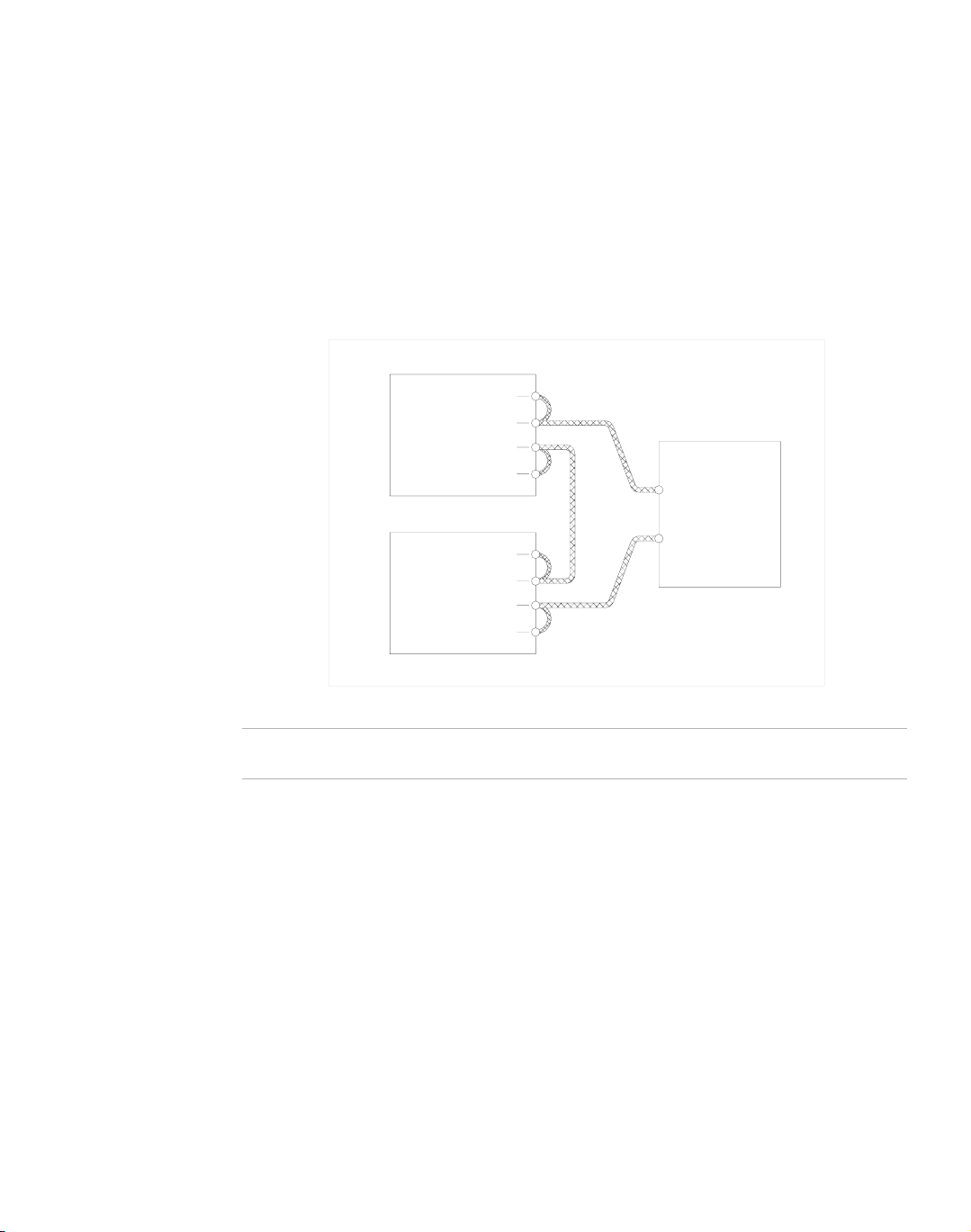
Configuring Multiple Supplies for Split Supply Operation
Split supply operating uses two power supplies to obtain two positive voltages with
a common ground, or to obtain a positive-negative supply.
Two Positive Voltages To obtain two positive voltages, connect the negative
output terminals of both supplies together in a common connection. The positive
output terminals will provide the required voltages with respect to the common
connection.
Postive Sense
Positive Output
Terminal
Negative Output
Terminal
Return Sense
Power Supply 1
Postive Sense
Positive Output
Terminal
Negative Output
Terminal
Return Sense
Load Lines
Use the largest gauge and
shortest length possible
Positive Load
Terminal #1
Postive Load
Terminal #2
Negative Load
Terminal
Load
Power Supply 2
Figure 3.4 Split Supply Operation of Multiple Supplies (Two positive voltages)
Release A 43
Page 46

Section 3. Local Operation
Using Multiple Supplies
Positive-negative supply To obtain a positive-negative supply, connect the
negative output terminal of one supply to the positive terminal of the second supply.
The positive output terminal of the first supply now provides a positive voltage
relative to the common connection. The negative output terminal of the second
supply provides the negative voltage. The current limits can be set independently of
each other. The maximum current available in split operation is equal to the rated
output of the supplies.
Postive Sense
Positive Output
Terminal
Negative Output
Terminal
Return Sense
Power Supply 1
Postive Sense
Positive Output
Terminal
Negative Output
Terminal
Return Sense
Load Lines
Use the largest gauge and
shortest length possible
Positive Load
Terminal
Common Load
Terminal
Negative Load
Terminal
Load
Power Supply 2
Figure 3.5 Split Supply Operation of Multiple Supplies (Positive-negative Supply)
Note Split supply operation requires the use of an isolated analog interface card on the
slave unit. In this arrangement, one-knob control of both supplies is possible
44 Operating Manual for XPD Series Power Supply
Page 47

User Diagnostics
If your power supply is not performing as described in this manual, run through the
procedures and checks in this section before calling your service technician. These
procedures are confined to operator level functions only. They do not require
cover-off servicing.
Section 3. Local Operation
User Diagnostics
Emergency
Shutdown
Unusual or
Erratic
Operation
In an emergency, carry out both of these steps:
1. Shut the power supply OFF immediately.
2. Disconnect the mains supply, if possible.
3. Disconnect the power supply from the load.
If the power supply displays any unusual or erratic operation, follow these steps:
1. Shut the power supply OFF immediately.
2. Disconnect the power supply from the load and external programming.
3. Test the power supply with no load, running the tests in “Functional Tests” on
page 29.
4. If the tests show that the power supply is functioning normally, check all load,
programming, and monitoring connections and circuits.
5. Check the AC input for correct voltage and frequency.
If the problem is not solved after you have followed this procedure, or if the unit fails
to operate correctly upon retesting, call your service technician.
Turn to “Trouble Shooting for Operators” below for more information about
troubleshooting for operators.
Trouble
Shooting for
Operators
Use the checks in Table 3 .2 to ensure that the power supply is configured and
connected for normal operation. If you need any further troubleshooting, call your
service technician.
Abbreviated References Used in Table
OVP over voltage protection
S/D shutdown
Release A 45
Page 48

Section 3. Local Operation
User Diagnostics
Table 3.2 User Diagnostics
Symptom Check Further Checks and Corrections
No output and the
display is blank.
No output but the
display turns on.
Output voltage not
adjustable.
In input voltage within
specified range?
Power switch ON? Turn on power.
Internal circuit? See your service technician.
OVP LED turned on? See
Connect to appropriate voltage
source. See
Connection” on page 28
“AC Input Power
.
“Using Over Voltage
Protection (OVP)” on page 38
Front panel S/D LED
turned on?
Current limit set to zero? See
Voltage control set to
zero?
REM LED turned on? If using remote analog control,
See
“Using the Shutdown
Function” on page 39
.
“Standard Operation” on page
35.
check your analog programming
source (See
“Remote Operation”
on page 49).
Internal circuit. See your service technician.
Is unit in current limit
mode? (Red Current
Limit mode LED turned
on.)
Is unit in remote
programming mode?
(Green PGM LED is
turned on.)
Is unit at maximum
voltage or current limit?
Turn current knob clockwise to
increase current limit. Reduce load
if current is at maximum. See
“Standard Operation” on page 35.
If using remote analog control,
check your analog programming
source (See
on page 49
digital interface manual.
Reduce load for lower voltage or
current requirement.
“Remote Operation”
). If not, refer to your
.
46 Operating Manual for XPD Series Power Supply
Page 49

Section 3. Local Operation
User Diagnostics
Symptom Check Further Checks and Corrections
Output voltage
fluctuating or
regulation poor.
Output oscillating. Internal circuit. See your service technician.
Is unit at current limit? Increase current limit setting or
reduce load. See
Operation” on page 35
Is input voltage within
specified range?
Connect to appropriate AC voltage
source. See
Connection” on page 28
Are sense lines
connected?
is unit under remote
analog control?
Internal circuit. See your service technician.
See
“Load Connection” on page
30
, and “Remote Sensing” on
page 33
Ensure that program source is
stable.
.
“Standard
.
“AC Input Power
.
Release A 47
Page 50

Section 3. Local Operation
User Diagnostics
48 Operating Manual for XPD Series Power Supply
Page 51

Section 4. Remote Operation
Introduction
The switches and connector on the rear panel of the power supply allow you to
program the supply with an analog device or to readback analog signals.
Remote
Digital
Programming
You can operate the power supply from a computer if you have the optional GPIB or
RS-232 interface card installed. Refer to the separate interface manual for all setup
and operation instructions for remote digital programming.
Remote Analog Programming of Output Voltage and Current Limit
Remote analog programming allows control of the power supply’s output voltage
and output current limit to shift from local operation at the front panel voltage and
current controls to external analog input sources. As you vary the programming
source, the power supply’s output varies proportionally over its output range.
Using remote analog programming requires that you make connections to the J210
connector on the power supply’s rear panel. See “Rear Panel J210 Connector” on
page 15. To reduce radiated emissions, add a ferrite block to the wires that go to the
J210 connector. The 1 inch square ferrite block with built in housing clip is packaged
and shipped with the power supply.
J210 connector
J210 cable Ferrite Block
Max. 5 cm
Figure 4.1 J210 User Cable with Ferrite Block
Release A 49
To user interface
Page 52

Section 4. Remote Operation
Readback and Status Indicators
Remote
Programming
Options
Programming
Output
Voltage with a
0-10 Vdc
Voltage
Source
Programming
Output
Current with
a 0-10 Vdc
Voltage
Source
See Table 4.1 for a summary of the options available to you for programming output
voltage and current limit using an analog source.
Table 4.1 Remote Programming Options
Control of... Programming Scale
Output voltage 0-10 V voltage sources
Current limit 0-10 V voltage sources
1. Connect J210 pin 6 (remote voltage program select) to J210 pin 8 (auxiliary ground).
2. Connect the control voltage source between pin 14 (voltage program) and pin 13
(program return).
3. Vary the external voltage from 0-10 Vdc to cause the power supply output to
vary from 0-100% of rated output voltage.
1. Connect J210 pin 7 (remote current program select) to J210 pin 8 (auxiliary ground).
2. Connect the control voltage source between J210 pin 5 (current program,
positive) and pin 8 (program return).
3. Vary the external voltage from 0-10 Vdc to cause the power supply current limit
to vary from 0-100% of rated output.
Readback and Status Indicators
Voltage and
Current
Readback
50 Operating Manual for XPD Series Power Supply
Voltage Readback Connect a voltage monitoring device between J210
connector pin 15 (voltage readback - positive) and pin 13 (program return negative).
Range: 0-10 V = 0-100% full rated voltage output of power supply
Current Readback Connect a voltage monitoring device between J210
connector pin 12 (current readback - positive) and pin 13 (program return negative).
Range: 0-10 V = 0-100% full rated current output of power supply
Page 53

Status Flags
Section 4. Remote Operation
Status Flags
The power supply has 5 status flags to indicate the operating state. The S/D LED on
the front panel, and 4 LEDs visible from the top of the unit. The flags, listed in order
from front to rear, are OTP, OVP, SNS-PROT and AC-FAIL.
OTP Over-temperature protection indicates a supply shutdown due to
over-temperature triggering the OTP circuitry. The unit has an
auto-restart feature when the supply’s temperature is within the correct
temperature range again.
OVP Over-voltage protection indicates shutdown due to output voltage
exceeding the threshold preset using the OVP trimpot on the front
panel.
SNS-PROT Sense line protection indicates a shutdown due to a voltage drop on the
load lines exceeding 5 V per line (3 V per line for 7.5 V model) in remote
sense mode. This condition may also occur if the unit is operated
without the J207 default sense line connector.
AC-FAIL AC fail indicates a mains V
(i.e. below 85 V
or over 264 V
ac
input out of the supply’s specified range
ac
ac).
In the event of one of the flags being tripped, the flag is raised along with S/D flag
on the front panel. An S/D flag with none of the other 4 flags indicates remote
shutdown (J210,1and 2).
Release A 51
Page 54

Section 4. Remote Operation
Status Flags
52 Operating Manual for XPD Series Power Supply
Page 55

Page 56

Xantrex Technology Inc.
8999 Nelson Way
Burnaby, British Columbia
Canada V5A 4B5
604 422 8595 Tel
604 421 3056 Fax
800 667 8422 Toll Free North America
prg.info@xantrex.com
www.xantrex.com
TM-PDOP-01XN
PRINTED IN CANADA
 Loading...