

Page 1

Xantrex Datacom
Inverter
XDI2048
2kVA/1.5kW
Operating Manual
Page 2

Page 3

Xantrex Datacom Inverter
XDI2048 2kVA/1.5kW
Operating Manual
Page 4

About Xantrex
Xantrex Technology Inc. is a world-leading supplier of advanced power electronics and controls with products
from 50 watt mobile units to one MW utility-scale systems for wind, solar, batteries, fuel cells, microturbines,
and backup power applications in both grid-connected and stand-alone systems. Xantrex products include
inverters, battery chargers, programmable power supplies, and variable speed drives that convert, supply, control,
clean, and distribute electrical power.
Trademarks
Xantrex Datacom Inverter is a trademark of Xantrex International. Xantrex is a registered trademark of Xantrex
International.
Other trademarks, registered trademarks, and product names are the property of their respective owners and are
used herein for identification purposes only.
Notice of Copyright
Xantrex Datacom Inverter Operating Manual © December 2003 Xantrex International. All rights reserved.
Disclaimer
UNLESS SPECIFICALLY AGREED TO IN WRITING, XANTREX TECHNOLOGY INC. (“XANTREX”)
(a) MAKES NO WARRANTY AS TO THE ACCURACY, SUFFICIENCY OR SUITABILITY OF ANY
TECHNICAL OR OTHER INFORMATION PROVIDED IN ITS MANUALS OR OTHER
DOCUMENTATION.
(b) ASSUMES NO RESPONSIBILITY OR LIABILITY FOR LOSS OR DAMAGE, WHETHER DIRECT,
INDIRECT, CONSEQUENTIAL OR INCIDENTAL, WHICH MIGHT ARISE OUT OF THE USE OF SUCH
INFORMATION. THE USE OF ANY SUCH INFORMATION WI LL BE ENTIRELY AT THE USER’S RISK.
Date and Revision
December 2003 Revision C
Part Number
TM-DIOP-01XN-01
Contact Information
Telephone: 1 800 670 0707 (toll free North America)
Fax: 1 800 994 7828 (toll free North America)
Email: customerservice@xantrex.com
Web: www.xantrex.com
1 360 925 5097 (direct)
1 360 925 5143 (direct)
Page 5

About This Manual
Purpose
The purpose of this Operating Manual is to provide explanations and
procedures for installing, operating, maintaining, and troubleshooting the
Xantrex Datacom Inverter.
Scope
The Manual provides safety guidelines, detailed planning and setup
information, procedures for installing the inverter, as well as information
about operating and troubleshooting the unit.
Audience
The Manual is intended for anyone who needs to install and operate the
Xantrex Datacom Inverter. Installers should be certified technicians or
electricians.
Organization
This Manual is organized into five chapters and an appendix:
Chapter 1, “Introduction”, Chapter 1 contains an introduction to the XDI
Inverter and the Ethernet card. This chapter provides a list of the major
features, protections and options included with both the XDI Inverter and
the Ethernet card.
Chapter 2, “Rack Mount Frame Assembly and Installation”, Chapter 2
contains information and procedures to assemble and install the rack mount,
and install the inverter.
TM-DIOP-01XN-01 iii
Page 6
About This Manual
Chapter 3, “Inverter Module Installation and Operation”, Chapter 3
contains information and procedures for installing and using the XDI
Inverter.
Chapter 4, “Remote Communication & Monitoring”, Chapter 4 contains
information and procedures for using the Ethernet to provide remote
communication and monitoring.
Chapter 5, “Troubleshooting”, Chapter 5 contains information and
procedures for troubleshooting your XDI Inverter and Ethernet card.
Appendix A, “Specifications”, Appendix A supplies information about
specifications for the XDI Inverter and the Ethernet.
Conventions Used
The following conventions are used in this guide.
WARNING
Warnings identify conditions that could result in personal injury or loss of life.
CAUTION
Cautions identify conditions or practices that could result in damage to the unit
or other equipment.
Important:
but not as serious as a caution or warning.
These notes describe things which are important for you to know,
Related Information
You can find more information about Xantrex Technology Inc. as well as
its products and services at www.xantrex.com
iv TM-DIOP-01XN-01
Page 7
Important Safety Instructions
WARNING
Operate the Inverter in an environment free of flammable gases or fumes. To
ensure that the Inverter’s safety features are not compromised, use the Inverter as
specified in this manual and do not substitute parts or make any unauthorized
modifications. Contact the service technician for service and repair help. Repairs
must be made by experienced service technicians only.
WARNING
The XDI is intended for installation in a restricted access location. This is an area
intended for qualified or trained personnel only, access to which is controlled by
a locking mechanism (for example, a key lock or an access card system).
WARNING
Appropriate care and attention must be exercised when connecting any
equipment to a DC supply system due to the short circuit energy hazard that
exists.
CAUTION
The inverter will operate from a DC source in the range of -40 V to -60 V. The
maximum voltage without damage to the unit is -80 V. The source and cabling
shall be capable of supplying 45 A continuously for a worst case operating
voltage of -40 V. Under overload conditions (maximum 3 kW) the source
requirement will be 90 A at -40 V
TM-DIOP-01XN-01 v
Page 8

vi
Page 9

Contents
Important Safety Instructions
1
Introduction
Inverter Information - - - - - - - - - - - - - - - - - - - - - - - - - - - - - - - - - - - - - - - - - - - -1–2
Description - - - - - - - - - - - - - - - - - - - - - - - - - - - - - - - - - - - - - - - - - - - - - - -1–2
Features and Options - - - - - - - - - - - - - - - - - - - - - - - - - - - - - - - - - - - - - - - - -1–2
Ethernet Information - - - - - - - - - - - - - - - - - - - - - - - - - - - - - - - - - - - - - - - - - - -1–3
Description - - - - - - - - - - - - - - - - - - - - - - - - - - - - - - - - - - - - - - - - - - - - - - -1–3
Features and Functions - - - - - - - - - - - - - - - - - - - - - - - - - - - - - - - - - - - - - - -1–3
Part Number and Ordering Information - - - - - - - - - - - - - - - - - - - - - - - - - - - - - - -1–4
2
Rack Mount Frame Assembly and Installation
Initial Inspection - - - - - - - - - - - - - - - - - - - - - - - - - - - - - - - - - - - - - - - - - - - - - -2–2
Packaging for Shipping or Storage - - - - - - - - - - - - - - - - - - - - - - - - - - - - - - -2–3
Introduction - - - - - - - - - - - - - - - - - - - - - - - - - - - - - - - - - - - - - - - - - - - - - - - - -2–4
Location, Mounting and Ventilation - - - - - - - - - - - - - - - - - - - - - - - - - - - - - - - - -2–5
Installation Into Cabinet Style Equipment Racks - - - - - - - - - - - - - - - - - - - - - -2–5
Installation into Relay Racks - - - - - - - - - - - - - - - - - - - - - - - - - - - - - - - - - - -2–6
DC Input Power- - - - - - - - - - - - - - - - - - - - - - - - - - - - - - - - - - - - - - - - - - - - - - -2–7
Input Connector and Cables - - - - - - - - - - - - - - - - - - - - - - - - - - - - - - - - - - - -2–7
DC Input Wire Connection - - - - - - - - - - - - - - - - - - - - - - - - - - - - - - - - - - - - -2–7
AC Load and Signal Line Connection - - - - - - - - - - - - - - - - - - - - - - - - - - - - - - - -2–9
AC Output Connector - - - - - - - - - - - - - - - - - - - - - - - - - - - - - - - - - - - - - - - -2–9
Load Wiring - - - - - - - - - - - - - - - - - - - - - - - - - - - - - - - - - - - - - - - - - - - - - -2–9
Load Connection - - - - - - - - - - - - - - - - - - - - - - - - - - - - - - - - - - - - - - - - - -2–10
User Line Connection - - - - - - - - - - - - - - - - - - - - - - - - - - - - - - - - - - - - - - -2–11
Overview - - - - - - - - - - - - - - - - - - - - - - - - - - - - - - - - - - - - - - - - - - - - -2–11
User Line Connector - - - - - - - - - - - - - - - - - - - - - - - - - - - - - - - - - - - - -2–12
User Line Wiring - - - - - - - - - - - - - - - - - - - - - - - - - - - - - - - - - - - - - - -2–12
User Line Connection - - - - - - - - - - - - - - - - - - - - - - - - - - - - - - - - - - - -2–12
TM-DIOP-01XN-01 vii
Page 10

Contents
CAN/SYNC Connector - - - - - - - - - - - - - - - - - - - - - - - - - - - - - - - - - - - - - - 2–13
Overview - - - - - - - - - - - - - - - - - - - - - - - - - - - - - - - - - - - - - - - - - - - - 2–13
Specifications: - - - - - - - - - - - - - - - - - - - - - - - - - - - - - - - - - - - - - - - - - 2–13
CAN/SYNC Connection - - - - - - - - - - - - - - - - - - - - - - - - - - - - - - - - - - 2–13
CAN/SYNC Wiring - - - - - - - - - - - - - - - - - - - - - - - - - - - - - - - - - - - - - 2–14
Connection Schemes - - - - - - - - - - - - - - - - - - - - - - - - - - - - - - - - - - - - - - - - - - 2–15
Stand-Alone Operation - - - - - - - - - - - - - - - - - - - - - - - - - - - - - - - - - - - - - - 2–15
Parallel Operation - - - - - - - - - - - - - - - - - - - - - - - - - - - - - - - - - - - - - - - - - 2–15
Connection - - - - - - - - - - - - - - - - - - - - - - - - - - - - - - - - - - - - - - - - - - - 2–15
Split Phase Operation - - - - - - - - - - - - - - - - - - - - - - - - - - - - - - - - - - - - - - - 2–17
Three Phase Operation - - - - - - - - - - - - - - - - - - - - - - - - - - - - - - - - - - - - - - 2–18
Overview - - - - - - - - - - - - - - - - - - - - - - - - - - - - - - - - - - - - - - - - - - - - 2–18
3-Phase Synchronization and Signal Wiring- - - - - - - - - - - - - - - - - - - - - - - - - - - 2–19
3-Phase, 3-Wire Delta Output Wiring - - - - - - - - - - - - - - - - - - - - - - - - - - - - 2–20
3-Phase, 3-Wire Y-Connection Output Wiring - - - - - - - - - - - - - - - - - - - - - - 2–20
3-Phase, 4-Wire Y-Connection Output Wiring - - - - - - - - - - - - - - - - - - - - - - 2–21
Ethernet Port- - - - - - - - - - - - - - - - - - - - - - - - - - - - - - - - - - - - - - - - - - - - - - - - 2–21
3
Inverter Module Installation and Operation
Installation into Rack Mount Frame - - - - - - - - - - - - - - - - - - - - - - - - - - - - - - - - - 3–2
Operation of Inverter Module - - - - - - - - - - - - - - - - - - - - - - - - - - - - - - - - - - - - -3–4
Theory of Operation - - - - - - - - - - - - - - - - - - - - - - - - - - - - - - - - - - - - - - - - -3–4
System Startup - - - - - - - - - - - - - - - - - - - - - - - - - - - - - - - - - - - - - - - - - - - - - 3–4
Standby Mode - - - - - - - - - - - - - - - - - - - - - - - - - - - - - - - - - - - - - - - - - - - - -3–5
Cooling Fans - - - - - - - - - - - - - - - - - - - - - - - - - - - - - - - - - - - - - - - - - - - - - -3–5
User Interface - - - - - - - - - - - - - - - - - - - - - - - - - - - - - - - - - - - - - - - - - - - - - - - - 3–6
Front Panel - - - - - - - - - - - - - - - - - - - - - - - - - - - - - - - - - - - - - - - - - - - - - - -3–6
User Lines - - - - - - - - - - - - - - - - - - - - - - - - - - - - - - - - - - - - - - - - - - - - - - - -3–6
Protections and Alarms- - - - - - - - - - - - - - - - - - - - - - - - - - - - - - - - - - - - - - - - - - 3–7
Overview - - - - - - - - - - - - - - - - - - - - - - - - - - - - - - - - - - - - - - - - - - - - - - - -3–7
Input Voltage Protection - - - - - - - - - - - - - - - - - - - - - - - - - - - - - - - - - - - - - -3–7
Output Voltage Protection - - - - - - - - - - - - - - - - - - - - - - - - - - - - - - - - - - - - -3–7
Overload Protection - - - - - - - - - - - - - - - - - - - - - - - - - - - - - - - - - - - - - - - - - 3–8
Over Temperature Protection (OTP) - - - - - - - - - - - - - - - - - - - - - - - - - - - - - - 3–9
Short-circuit Protection - - - - - - - - - - - - - - - - - - - - - - - - - - - - - - - - - - - - - - - 3–9
Over-Current protection - - - - - - - - - - - - - - - - - - - - - - - - - - - - - - - - - - - - - -3–9
Internal Diagnostics - - - - - - - - - - - - - - - - - - - - - - - - - - - - - - - - - - - - - - - - - 3–9
viii TM-DIOP-01XN-01
Page 11

Fuses and Grounding - - - - - - - - - - - - - - - - - - - - - - - - - - - - - - - - - - - - - - - -3–10
Incorrect Connection Protection - - - - - - - - - - - - - - - - - - - - - - - - - - - - - - - -3–10
Output (AC) Alarm - - - - - - - - - - - - - - - - - - - - - - - - - - - - - - - - - - - - - - - - -3–10
To Clear an Alarm - - - - - - - - - - - - - - - - - - - - - - - - - - - - - - - - - - - - - - - - -3–11
Maintenance - - - - - - - - - - - - - - - - - - - - - - - - - - - - - - - - - - - - - - - - - - - - - - - -3–11
4
Remote Communication & Monitoring
Introduction - - - - - - - - - - - - - - - - - - - - - - - - - - - - - - - - - - - - - - - - - - - - - - - - -4–2
Web-enabled User Interface- - - - - - - - - - - - - - - - - - - - - - - - - - - - - - - - - - - - - - -4–2
Initial Setup - - - - - - - - - - - - - - - - - - - - - - - - - - - - - - - - - - - - - - - - - - - - - - - - -4–2
Introduction - - - - - - - - - - - - - - - - - - - - - - - - - - - - - - - - - - - - - - - - - - - - - - -4–2
How to Setup For the First Time - - - - - - - - - - - - - - - - - - - - - - - - - - - - - - - - -4–4
Hardware Setup - - - - - - - - - - - - - - - - - - - - - - - - - - - - - - - - - - - - - - - - -4–4
Ethernet Setup - - - - - - - - - - - - - - - - - - - - - - - - - - - - - - - - - - - - - - - - - -4–5
Resetting - - - - - - - - - - - - - - - - - - - - - - - - - - - - - - - - - - - - - - - - - - - - - -4–6
Operating Instructions - - - - - - - - - - - - - - - - - - - - - - - - - - - - - - - - - - - - - - - - - -4–9
Introduction - - - - - - - - - - - - - - - - - - - - - - - - - - - - - - - - - - - - - - - - - - - - - - -4–9
Network Connection - - - - - - - - - - - - - - - - - - - - - - - - - - - - - - - - - - - - - - - - -4–9
Using DHCP - - - - - - - - - - - - - - - - - - - - - - - - - - - - - - - - - - - - - - - - - - - - -4–11
What Power On Does - - - - - - - - - - - - - - - - - - - - - - - - - - - - - - - - - - - - - - - 4–11
Password - - - - - - - - - - - - - - - - - - - - - - - - - - - - - - - - - - - - - - - - - - - - - - - -4–12
Automatic Power-On Email - - - - - - - - - - - - - - - - - - - - - - - - - - - - - - - - - - -4–13
How to Use the Web Interface - - - - - - - - - - - - - - - - - - - - - - - - - - - - - - - - -4–13
Manage Page - - - - - - - - - - - - - - - - - - - - - - - - - - - - - - - - - - - - - - - - - -4–14
Setup Page - - - - - - - - - - - - - - - - - - - - - - - - - - - - - - - - - - - - - - - - - - - -4–15
Monitor page - - - - - - - - - - - - - - - - - - - - - - - - - - - - - - - - - - - - - - - - - -4–17
Automatic Shutdown Email - - - - - - - - - - - - - - - - - - - - - - - - - - - - - - - - - - -4–19
Contents
5
Troubleshooting
User Diagnostics - - - - - - - - - - - - - - - - - - - - - - - - - - - - - - - - - - - - - - - - - - - - - -5–2
Emergency Shutdown - - - - - - - - - - - - - - - - - - - - - - - - - - - - - - - - - - - - - - - -5–2
Unusual or Erratic Operation - - - - - - - - - - - - - - - - - - - - - - - - - - - - - - - - - - -5–2
Diagnostic Guide - - - - - - - - - - - - - - - - - - - - - - - - - - - - - - - - - - - - - - - - - - -5–3
TM-DIOP-01XN-01 ix
Page 12

Contents
A
Specifications
Inverter Specifications - - - - - - - - - - - - - - - - - - - - - - - - - - - - - - - - - - - - - - - - - A–2
Electrical Specifications - - - - - - - - - - - - - - - - - - - - - - - - - - - - - - - - - - - - - A–2
Regulatory Approvals - - - - - - - - - - - - - - - - - - - - - - - - - - - - - - - - - - - - - - - A–4
Environmental Specifications - - - - - - - - - - - - - - - - - - - - - - - - - - - - - - - - - - A–4
Mechanical Specifications - - - - - - - - - - - - - - - - - - - - - - - - - - - - - - - - - - - - A–5
Ethernet Specifications- - - - - - - - - - - - - - - - - - - - - - - - - - - - - - - - - - - - - - - - - A–7
Warranty and Product Information
Warranty - - - - - - - - - - - - - - - - - - - - - - - - - - - - - - - - - - - - - - - - - - - - - - - - - - -B–1
Return Material Authorization Policy - - - - - - - - - - - - - - - - - - - - - - - - - - - - - - - -B–3
Return Procedure- - - - - - - - - - - - - - - - - - - - - - - - - - - - - - - - - - - - - - - - - - - - - -B–4
Out of Warranty Service- - - - - - - - - - - - - - - - - - - - - - - - - - - - - - - - - - - - - - - - -B–4
Information About Your System - - - - - - - - - - - - - - - - - - - - - - - - - - - - - - - - - - -B–4
xTM-DIOP-01XN-01
Page 13

Figures
Figure 2-1 Packing List - - - - - - - - - - - - - - - - - - - - - - - - - - - - - - - - - - - - - - - - - - 2–2
Figure 2-2 Shipping or Storage Carton Label- - - - - - - - - - - - - - - - - - - - - - - - - - - - 2–3
Figure 2-3 Rack Mount Frame Rear View- - - - - - - - - - - - - - - - - - - - - - - - - - - - - - 2–4
Figure 2-4 Installing into Cabinet Style Racks- - - - - - - - - - - - - - - - - - - - - - - - - - - 2–5
Figure 2-5 Installing into Relay Racks - - - - - - - - - - - - - - - - - - - - - - - - - - - - - - - - 2–6
Figure 2-6 Connecting the Input Wires- - - - - - - - - - - - - - - - - - - - - - - - - - - - - - - - 2–8
Figure 2-7 User Lines Schematic- - - - - - - - - - - - - - - - - - - - - - - - - - - - - - - - - - - 2–11
Figure 2-8 Parallel Operation - - - - - - - - - - - - - - - - - - - - - - - - - - - - - - - - - - - - - 2–16
Figure 2-9 Split-Phase Operation- - - - - - - - - - - - - - - - - - - - - - - - - - - - - - - - - - - 2–17
Figure 2-10 3-Phase Sync Connection - - - - - - - - - - - - - - - - - - - - - - - - - - - - - - - - 2–19
Figure 3-1 Installing an Inverter into a Rack - - - - - - - - - - - - - - - - - - - - - - - - - - - - 3–3
Figure 3-2 Inverter Front Panel - - - - - - - - - - - - - - - - - - - - - - - - - - - - - - - - - - - - - 3–3
Figure 3-3 Overload curve - - - - - - - - - - - - - - - - - - - - - - - - - - - - - - - - - - - - - - - - 3–8
Figure 3-4 Replacing the Fan Filters - - - - - - - - - - - - - - - - - - - - - - - - - - - - - - - - 3–12
Figure 4-1 Ethernet Interface PCB- - - - - - - - - - - - - - - - - - - - - - - - - - - - - - - - - - - 4–3
Figure 4-2 First Time Setup Connections - - - - - - - - - - - - - - - - - - - - - - - - - - - - - - 4–4
Figure 4-3 Removing Unit’s Top Cover - - - - - - - - - - - - - - - - - - - - - - - - - - - - - - - 4–7
Figure 4-4 Ethernet Reset Jumper - - - - - - - - - - - - - - - - - - - - - - - - - - - - - - - - - - - 4–8
Figure 4-5 Network Setup - - - - - - - - - - - - - - - - - - - - - - - - - - - - - - - - - - - - - - - 4–10
Figure 4-6 Password Confirmation Boxes- - - - - - - - - - - - - - - - - - - - - - - - - - - - - 4–12
Figure 4-7 Manage Page of Web Interface - - - - - - - - - - - - - - - - - - - - - - - - - - - - 4–14
Figure 4-8 Setup Page of Web Interface - - - - - - - - - - - - - - - - - - - - - - - - - - - - - - 4–15
Figure 4-9 Monitor Page of Web Interface - - - - - - - - - - - - - - - - - - - - - - - - - - - - 4–17
Figure A-1 Inverter and Rack Mount Frame Dimensions - - - - - - - - - - - - - - - - - - - - A–6
TM-DIOP-01XN-01 xi
Page 14

xii
Page 15

Tables
Table 2-1 User Line Connection- - - - - - - - - - - - - - - - - - - - - - - - - - - - - - - - - - - 2–12
Table 2-2 CAN/SYNC Pin-out- - - - - - - - - - - - - - - - - - - - - - - - - - - - - - - - - - - - 2–14
Table 2-3 3-Phase Configurations- - - - - - - - - - - - - - - - - - - - - - - - - - - - - - - - - - 2–18
Table 3-1 Front Panel LED Functions- - - - - - - - - - - - - - - - - - - - - - - - - - - - - - - - 3–6
Table 3-2 User Line Pins- - - - - - - - - - - - - - - - - - - - - - - - - - - - - - - - - - - - - - - - - 3–6
Table 4-1 Default Settings- - - - - - - - - - - - - - - - - - - - - - - - - - - - - - - - - - - - - - - - 4–5
Table 4-2 User Configured Settings - - - - - - - - - - - - - - - - - - - - - - - - - - - - - - - - - 4–6
Table 4-3 Reset Settings - - - - - - - - - - - - - - - - - - - - - - - - - - - - - - - - - - - - - - - - - 4–7
Table 4-4 Manage Page of Web Interface - - - - - - - - - - - - - - - - - - - - - - - - - - - - 4–14
Table 4-5 Setup Page of Web Interface - - - - - - - - - - - - - - - - - - - - - - - - - - - - - - 4–16
Table 4-6 Monitor Page of Web Interface - - - - - - - - - - - - - - - - - - - - - - - - - - - - 4–18
Table 4-7 Shutdown Code- - - - - - - - - - - - - - - - - - - - - - - - - - - - - - - - - - - - - - - 4–19
Table 5-1 Inverter Diagnostics- - - - - - - - - - - - - - - - - - - - - - - - - - - - - - - - - - - - - 5–3
Table 5-2 Ethernet Diagnostics - - - - - - - - - - - - - - - - - - - - - - - - - - - - - - - - - - - - 5–4
TM-DIOP-01XN-01 xiii
Page 16

xiv
Page 17

1
Introduction
Chapter 1 contains an introduction to the XDI Inverter and the
Ethernet card. This chapter provides a list of the major features,
protections and options included with both the XDI Inverter and
the Ethernet card.
Page 18

Introduction
Inverter Information
Description
The Xantrex Datacom Inverter (patent pending) is the most versatile
modular rack mounted Inverter system for telecom and industrial
applications requiring constant AC power from standard –48 V battery
systems. The XDI consists of a 1 U (1.7 in, 73 mm) thin, true sinewave
2000 VA/1500 W inverter module rated for continuous duty, and a
compatible 19-inch wide equipment rack mount frame with back-plane
mounted connectors. The system is easily scalable by adding parallelconnected modules and can be configured in N+1 single or three-phase
arrays for maximum reliability. No single unit is a “master”, and an array
of units will tolerate the failure of one or more parallel-connected
inverters.
Features and Options
Product
Features
Protection
Features
Options • Optional TCP/IP enabled Ethernet port card
• Compact size (1 U) designed to fit standard 19 in (483 mm)
equipment racks
• Easily paralleled for N+1 redundant systems
• High efficiency and reliability
• Power share in parallel system for up to 20 kVA (10 units) of AC
power
• 3 kW, 4 kVA (5 s) surge capability
• Short circuit proof
• Rack mounted back plane accommodates DC input and AC output
connectors
• High performance noise filters on both input and output
• 3-year warranty
• cCSAus, CE, NEBS LEVEL 3, FCC Class B approvals
• Input under/over voltage protection
• Output under/over voltage protection
• Incorrect connection protection
• Temperature limit shutdown
• Output overload protection
• Optional static transfer switch for added system reliability
1-2 TM-DIOP-01XN-01
Page 19

Ethernet Information
Ethernet Information
Description
The internal XDI Ethernet interface allows you to monitor and operate
your inverter from a local or remote computer equipped with an Ethernet
card.
The Ethernet interface allows monitoring and configuration of the XDI
Inverter as well as network settings for the interface card itself. The
interaction is done through an HTTP server and a custom Web page
served by the Ethernet interface.
A proactive emailing system uses SMTP to inform you that the unit has
turned on or a fault condition has occurred.
This section describes the features and specifications of the XDI Ethernet
interface card.
Features and Functions
Features • No special software required to monitor/control XDI Inverter (Simple
Web browser will work)
• Easy to use Web page interface
• Automatically sends email when XDI is powered on
• Automatically sends email when XDI shuts down
• Allows remote monitor from any PC with Internet access
• Possible re-use of network cable infrastructure for connections
• Password protected for added security
Programmable
Functions
• Output Standby Mode
• Password
• Default IP address
• Gateway IP address
• Sub-Net Mask
• Domain Name Server #1
• Domain Name Server #2
• SMTP Server
• Email Alert Address
TM-DIOP-01XN-01 1-3
Page 20

Introduction
Monitor
Functions
• DSP Firmware Version
• Manufacturer
•Model
• Serial Number
• Front Panel LED status
• Output Voltage
• Output Current
• Percent Load
• Startup State
• Current Fault Status
• Faults Since Power On
Part Number and Ordering Information
XDI2048-RM Includes Inverter Module and Rack Mount Frame.
Ready to install into 19 in. (483 mm) standard
equipment rack.
XDI2048HV-RM (“HV” for 230 V/50 Hz output)
XDI2048 Includes Inverter Module only . Ready to insert into
a pre-wired Rack Mount Frame.
XDI2048HV (“HV” for 230 V/50 Hz output)
ENET -XDI Optional factory-installed TCP/IP enabled Ethernet
communications card.
RM-XDI Includes Rack Mount Frame Assembly. Ready to
be installed in a 19 in. (483 mm) standard
equipment rack.
RM-1U23 Optional Rack Mount Adapter Kit to mount
equipment into a 23 in. (585 mm) standard
equipment rack.
1-4 TM-DIOP-01XN-01
Page 21

Rack Mount Frame
2
Assembly and
Installation
Chapter 2 contains information and procedures to assemble and
install the rack mount, and install the inverter.
This chapter describes the following:
• rack mounting the Inverter
• connecting the DC input power
• connecting the AC load and signal line
• setting up a variety of operating formats
Page 22
Rack Mount Frame Assembly and Installation
Initial Inspection
When you first receive your unit, perform a quick physical check.
1. Inspect the unit for scratches and cracks, broken switches, connectors,
terminals, and missing accessories.
2. Have a service technician check the unit if you suspect internal
damage.
If the unit is damaged, save all packing materials and notify the carrier
immediately. See instructions in “Packaging for Shipping or Storage” on
page 2–3 and “Return Procedure” on page B–4.
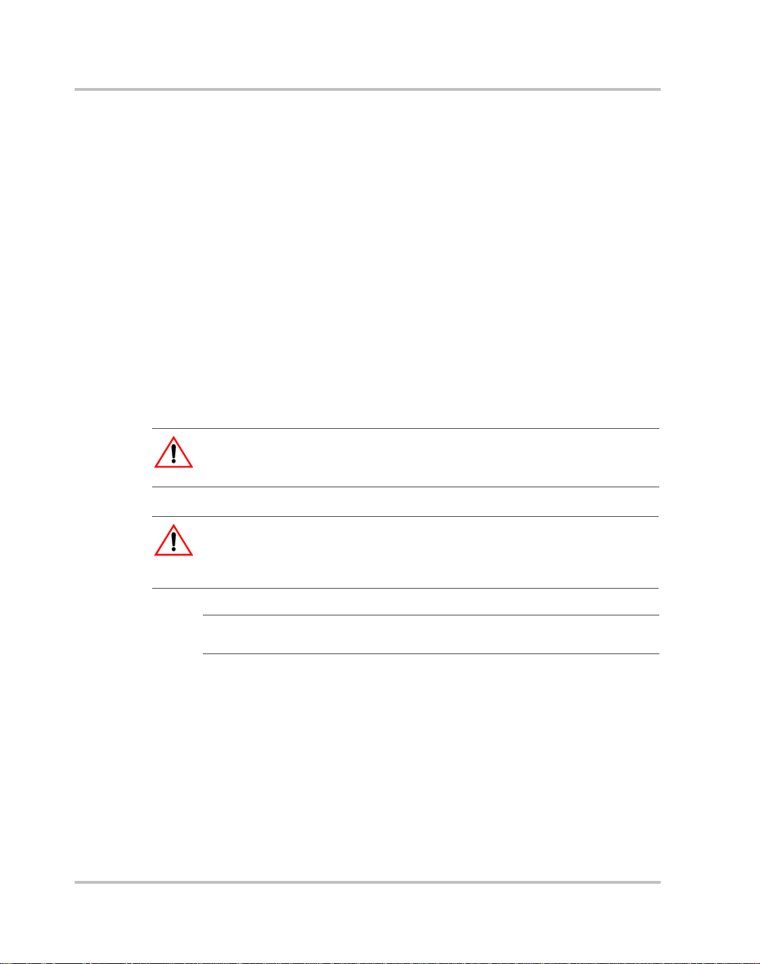
Your purchase should ship with the following items:
INVERTER MODULE
RACK MOUNT BACKPLANE
RELAY RACK MOUNTING BRACKETS
SLIDING RAILS
OUTPUT STRAIN RELIEF COVER
USER MANUAL
MANUAL
Figure 2-1
2-2 TM-DIOP-01XN-01
Packing List
Page 23

Packaging for Shipping or Storage
Follow these instructions to prepare the unit for shipping or storage.
1. When returning the unit or sending it to the service center, attach a tag
to the unit stating its model number (available from the front panel
label) and its serial number (available from the rear panel label). Give
the date of purchase and an invoice number, if you have it, as well as
a brief description of the problem. You will need an RMA number to
return the unit. See “Return Material Authorization Policy” and
“Return Procedure” on page B–4.
2. For storage or shipping, repack the inverter in its original container. If
the original container is not available, seal the unit in a plastic bag and
then pack it in a 200 lb. (90 kg) test, corrugated cardboard carton
large enough to allow 2 in (50 mm) of cushioning material to
surround the unit. Use a material such as foam slabs or chips.
3. Label the carton as shown in Figure 2-2.
4. If shipping, mark the address of the service center and your return
address on the carton.
5. If storing, stack no more than eight cartons high. Check the storage
temperature range and storage altitude specification in
“Environmental Specifications” on page A–4.
Initial Inspection
INVERTER
Model Number: _______________________
Serial Number: _______________________
FRAGILE — ELECTRONIC EQUIPMENT
Figure 2-2
TM-DIOP-01XN-01 2-3
Shipping or Storage Carton Label
Page 24
Rack Mount Frame Assembly and Installation
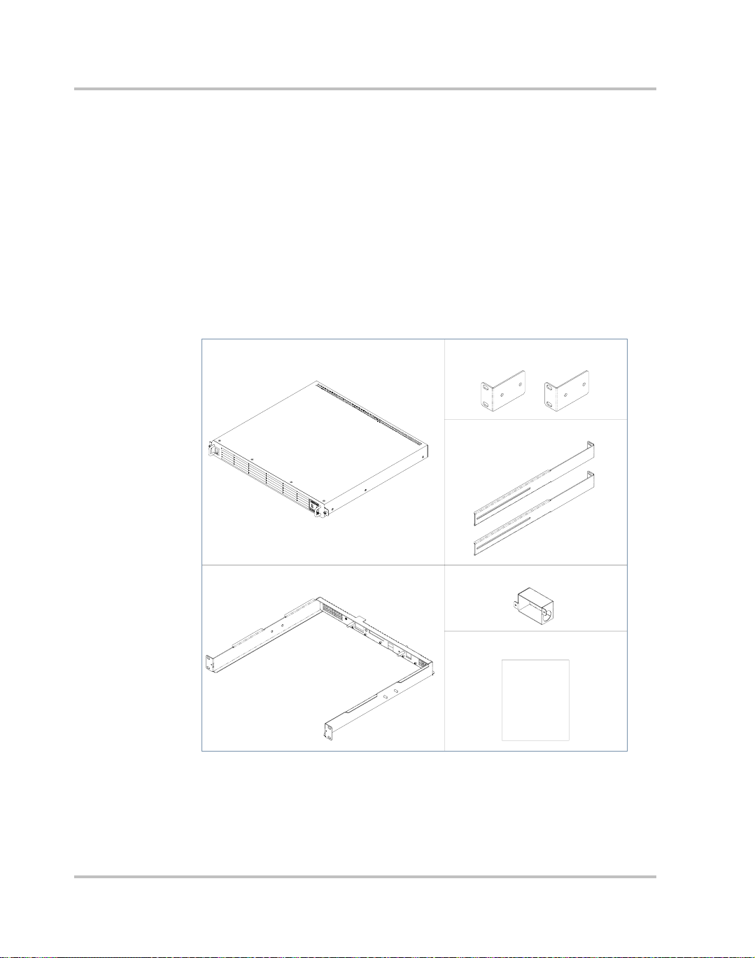
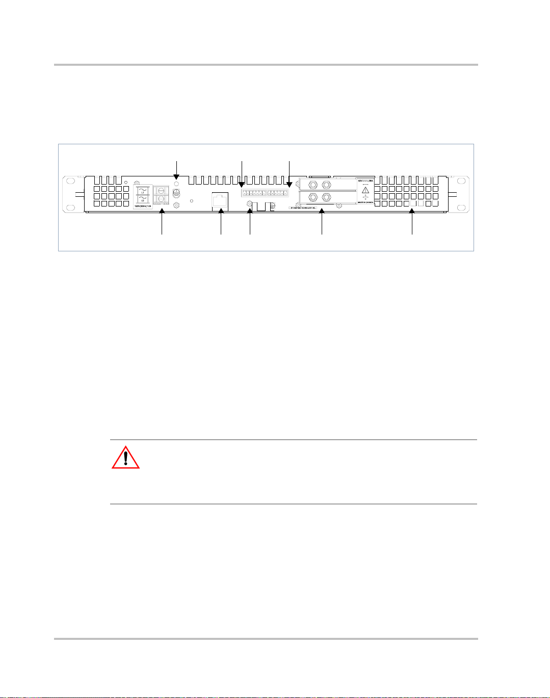
Introduction
You can use the Inverter in rack-mounted applications. Alternate
configurations can be created for custom applications.
246
Figure 2-3
ETHERNET
135 7 8
Rack Mount Frame Rear View
1. AC Output Terminal Block
2. AC Output Ground Stud
3. Ethernet card (optional)
4. Can/Sync Connector
5. DC Input Ground Stud
6. User Lines Connector
7. DC Input Terminal Block
8. Air Vents
WARNING
The XDI is intended for installation in a restricted access location. This is an area
intended for qualified or trained personnel only, access to which is controlled by
a locking mechanism (for example, a key lock or an access card system).
CAN/SYNC USER LINES
1234567 123456
2-4 TM-DIOP-01XN-01
Page 25
Location, Mounting and Ventilation
Location, Mounting and Ventilation
When you install the Inverter into a rack, allow cooling air to reach the
ventilation inlets. At the same time, do not block the air exhaust. See
“Electrical Specifications” on page A–2 for the operating altitude
specification and the operating ambient temperature range measured at
the unit case.
The inverter is designed to fit into a standard 19 in. (483 mm) equipment
rack. Mounting brackets are included which allow the unit to be mounted
in either cabinet style racks or relay racks.
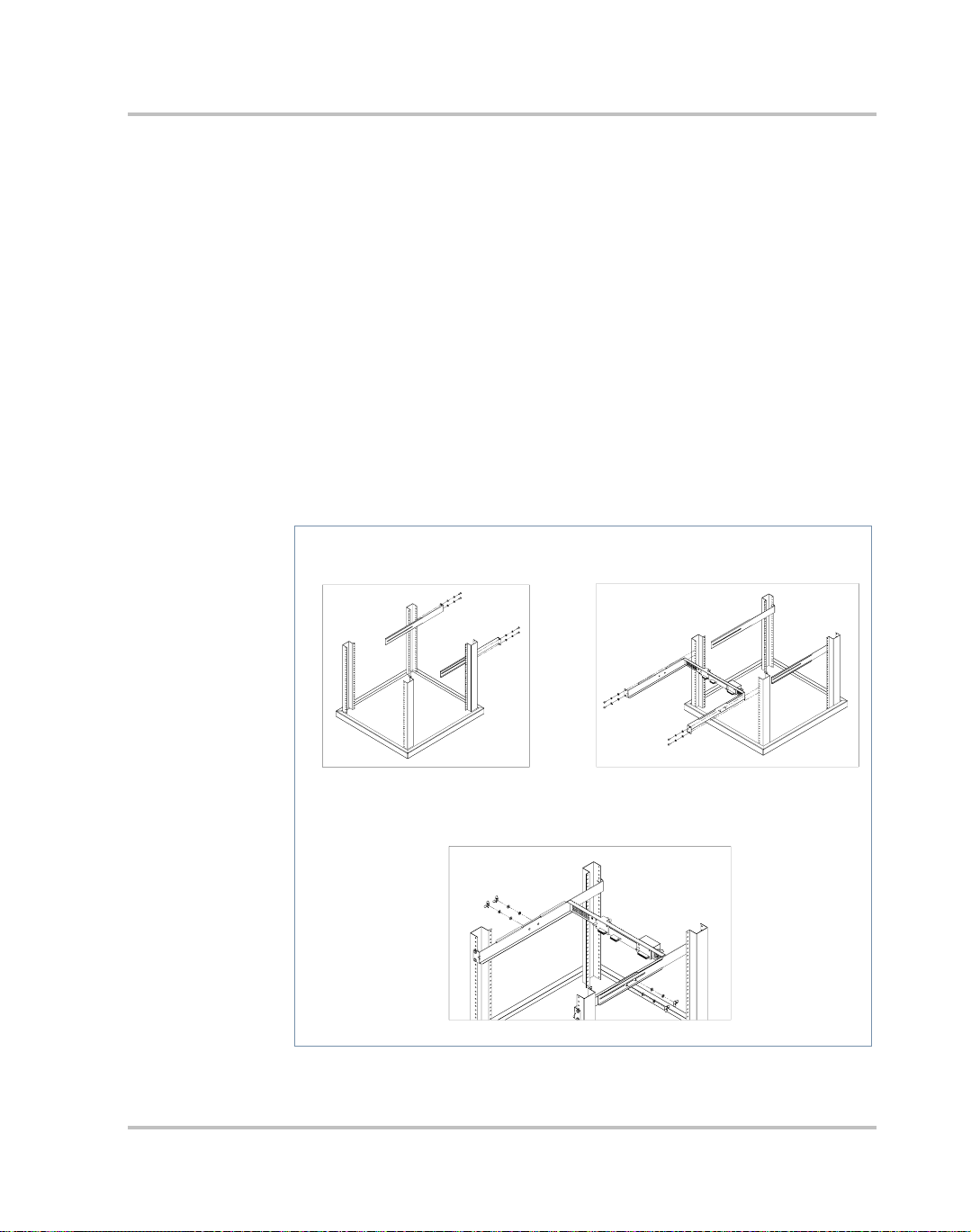
Installation Into Cabinet Style Equipment Racks
For installation into a cabinet style equipment rack, the backplane is
secured using two sliding rails as shown below.
2. Assemble the Backplane1. Assemble the Sliding Rails
3. Secure the Backplane
Figure 2-4
TM-DIOP-01XN-01 2-5
Installing into Cabinet Style Racks
Page 26
Rack Mount Frame Assembly and Installation
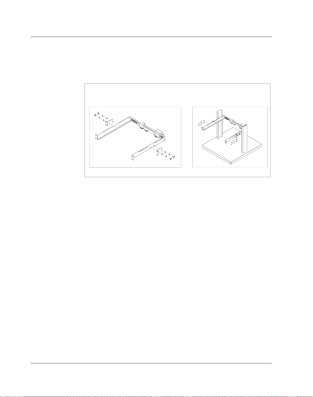
Installation into Relay Racks
Use the supplied mounting brackets to secure the backplane in a relay
rack.
2. Assemble in Relay Rack1. Attach the Mounting Brackets
Figure 2-5
Installing into Relay Racks
2-6 TM-DIOP-01XN-01
Page 27

DC Input Power
CAUTION
The inverter will operate from a DC source in the range of -40 V to -60 V. The
maximum voltage without damage to the unit is -80 V. The source and cabling
shall be capable of supplying 45 A continuously for a worst case operating
voltage of -40 V. Under overload conditions (maximum 3 kW) the source
requirement will be 90 A at -40 V
Input Connector and Cables
The XDI input connector is a 2-pole, double lug terminal block with
separate double studs for the ground connection. A minimum of 6 AWG
copper conductor (rated 85°C minimum) is the recommended wire gauge
for all three input cables.
DC Input Wire Connection
DC Input Power
Important:
that the installation complies with the specific wiring rules applicable to your
country or area of jurisdiction.
The DC input wiring should be routed through a 60 A circuit breaker for
each inverter used. This provides additional disconnect options and adds
to safety. A 2-pole breaker is recommended, but should a single pole be
used, it should be mounted in the negative side of the input wiring.
To connect DC input wires from the breaker:
1. Ensure DC breaker is de-energized.
2. Strip 7/16 in. (11 mm) off the positive, negative and ground cables
and install a standard two hole compression lug (hole diameter:
0.25 in. (6 mm)) on each cable.
• Burndy part #: YA6CL2TC14
• T&B part #: 54205
• Hendry part #: 06117-01
3. Remove the supplied nut and washer on the ground studs and install
and secure the ground connection.
The following procedure should be used as a guide only. Ensure
TM-DIOP-01XN-01 2-7
Page 28
Rack Mount Frame Assembly and Installation
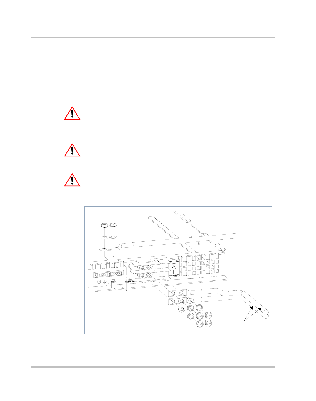
4. Note the polarity on the input connector as indicated and fasten the
positive and negative cable ends onto the terminal block using the
brass screws and washers provided. Tighten both securely . See Figure
2-6.
5. The DC input wiring should be appropriately restrained to the
equipment rack to provide strain relief.
WARNING
Appropriate care and attention must be exercised when connecting any
equipment to a DC supply system due to the short circuit energy hazard that
exists.
WARNING
It is critical that the wires be stripped the right length so that the insulator enters
the connector.
WARNING
T o avoid the risk of a short-circuit hazard, bare wire must NOT protrude past the
connector.
DC Input
Figure 2-6
2-8 TM-DIOP-01XN-01
Connecting the Input Wires
Page 29

AC Load and Signal Line Connection
AC Load and Signal Line Connection
Important:
that the installation complies with the specific wiring rules applicable to your
country or area of jurisdiction.
AC Output Connector
This is a two terminal barrier strip for use with up to #12 AWG wire. The
two terminals, L1 & L2 are floating outputs, L1 or L2 can be grounded to
simulate a neutral conductor. The barrier strip will accept a maximum lug
width of 0.32 in. (8.1 mm). The recommended torque on the screw is 9 inlbs.
Load Wiring
When selecting load wiring, consider the following factors:
• Current carrying capacity of the wire
• Maximum wire length
• Maximum ambient temperature
• Noise effects on signal lines
Use the table below as a guide to help identify wiring requirements for
permanent connection to an AC distribution box. The distribution box
shall include a 2 pole appropriately rated circuit breaker in series with
each inverter used in an array of units. The guide below applies for up to
2.5m long load terminations. Consider other means such as bus bar
distribution for longer runs.
The following procedure should be used as a guide only. Ensure
AC Output Voltage Wire
120 Minimum 3 x 16 AWG (2 wire plus safety ground),
stranded copper 105°C, 300 V
220-230 Minimum 3 x 16 AWG (2 wire plus safety ground),
stranded copper 105°C, 300 V
TM-DIOP-01XN-01 2-9
Page 30

Rack Mount Frame Assembly and Installation
Load Connection
WARNING
Exercise caution when making connections to a rack in an existing installation.
Ensure all input and output breakers are de-energized and that adjacent racks are
also powered down.
1. If necessary, remove the output cover by loosening the two securing
nuts. Release the clamp on the strain relief and insert one end of the
load wire
2. Strip and install appropriately sized spade or ring terminals on the two
load lines. Only use a ring type terminal for the safety ground
connection.
[70 mm]
1.97"
[50 mm]
2.76
"
GROUND
LINE 1
LINE 2
3. Loosen or remove the two screws on the barrier strip and insert the
load connections noting polarity if neutral is chosen. Tighten screws
to secure.
4. Connect the safety ground wire to the ground stud provided. The
ground stud accepts a 0.2 in. (5 mm) #10 diameter ring terminal.
5. Route the load wires inside the cover to prevent pinching but with a
sufficient service loop. Replace cover and secure. Tighten clamping
screw on strain relief to secure wire in place.
2-10 TM-DIOP-01XN-01
Page 31

User Line Connection
Overview
The User-line interface provides basic remote control and monitoring on
the Inverter using TTL logic signals. The available signals are an Inverter
on/off input, fault and Inverter-on flags as well as a configurable auxiliary
line. The aux output can only be configured when the Ethernet option
card is installed. The user lines are optically isolated with typical source/
sink capability of 10 mA. To prevent damage to this interface, do not
exceed 40 mA of source/sink current.
CAUTION
Do not bias this port more than 50 V DC to chassis.
AC Load and Signal Line Connection
Figure 2-7
TM-DIOP-01XN-01 2-11
User Lines Schematic
Page 32

Rack Mount Frame Assembly and Installation
User Line Connector
The user-line is a 6-position wire clamp connector adjacent to the DC
input connector. Table 2-1 lists user functions and associated terminal
numbers.
User Line Wiring
Use twisted pairs of 22-24 AWG for connections. Before making any
connections, ensure power to the rack has been disconnected. Carefully
route the wires away from high power load cables to minimize noise
effects on signal integrity .
User Line Connection
Use this table to wire appropriate signals.
Table 2-1
Terminal Label I/O Logic Level Function
1 User line return GND GND GND reference
2 User shutdown Input Active high Shuts down
3 Fault Flags Output Active high Inverter faults
4 AUX flag Output N/A User configurable
5 Inverter flag Output Active high Inverter on-line
6 Not used N/A N/A N/A
User Line Connection
inverter
User line voltages are below:
Inputs
High
Low
Outputs
High
Low
1.25 V to 5 V
0.0 V to 1.25 V
5V
1.5 V max.
2-12 TM-DIOP-01XN-01
Page 33

CAN/SYNC Connector
Overview
The CAN/SYNC connector provides access to functions necessary for
operation of multiple units in parallel, series or three phase. The
connector is a 7-position wire clamp adjacent to the user-line. T w o sets of
signals are provided on this connector:
• Can-bus: Paralleled units relay data necessary to achieve load sharing
between units using this arbitration bus. The protocol used is
proprietary hence cannot be and should not be interfaced to different
products.
• Sync-lines: Used to configure and synchronize units in parallel, series
or 3 phase.
Specifications:
Maximum number of units 10
Bus Speed 1 Mb/sec
Termination 120 Ω 1/4 W
AC Load and Signal Line Connection
Addresses 1 to 10
CAN/SYNC Connection
Table 2-2 outlines the pinout of the terminal. See connection schemes for
wiring method applicable to your requirements.
TM-DIOP-01XN-01 2-13
Page 34

Rack Mount Frame Assembly and Installation
CAN/SYNC Wiring
Due to high bus speed, use shielded twisted pairs of 22-24 AWG for
improved noise immunity . Before ma king any connections, ensure power
to the rack has been disconnected. Carefully route the wires away from
high power load cables to minimize noise effects on signal integrity.
Table 2-2
Terminals Function
1 Return/GND
2 CAN-LO
3 CAN-HI
4 Return/GND
5 SYCN-OUT 240 degrees
6 SYCN-OUT 120 degrees
7 SYCN-OUT 0 degrees
CAN/SYNC Pin-out
2-14 TM-DIOP-01XN-01
Page 35

Connection Schemes
CAUTION
Before attempting any connections, ensure power to rack is off by de-energizing
input and output circuit breakers.
This section covers the realization of different output configurations available
with this product line.
Stand-Alone Operation
A 120 Ohm resistor should be connected across the CAN-hi and CAN-lo
terminals to properly terminate the bus. No other connections to this port
are necessary for single unit operation.
Parallel Operation
When operated in this mode, up to ten XDI inverters can operate on a
single bus by daisy chaining the canbus lines. Any additional units above
this will still operate autonomously and not participate in load sharing
arbitration. At power-up, the first ten units to access the bus acquire a
unique I.D. each, beyond which no more I.D.s are made available. No
unique master exists in a parallel system. All units continuously execute a
complex algorithm to determine the load current based on the number of
units online and the highest individual current. This ensures no
interruption to the load should any unit in the system fail or is turned off.
Connection Schemes
Connection
• Make connections to the CAN/SYNC connector using its screw-type
wire clamps. It may be necessary to remove the mating connector to
facilitate connections to the terminal. Daisy chain the CAN-bus lines
across all units in parallel (i.e. all CAN-hi terminals are connected
together and likewise for CAN-lo). 120 Ohm terminating resistors
must be connected across the CAN terminals of the first and last units
in the chain.
• Also daisy chain the “SYNC-OUT 0” and “return” terminals on the
connector. This provides phase lock between paralleled units. See
Figure 2-8.
TM-DIOP-01XN-01 2-15
Page 36

Rack Mount Frame Assembly and Installation
Figure 2-8
Parallel Operation
L1
1
L2
L1
L2
1
L1
L2
1
7
5
3
26
4
7
5
36
2
4
75
36
4
2
• The AC output load wires are also connected in parallel ensuring only
like terminals L1 and L2 are connected together at the distribution
bus or load. Each inverter output should be in series with a suitably
rated two pole circuit breaker before being terminated at the load.
2-16 TM-DIOP-01XN-01
Page 37

Split Phase Operation
Use this scheme to extend the output voltage. No more than two units
should be connected in series though more can be added in parallel with
either series unit.
To connect two units for split voltage, proceed as follows:
• First ensure power to the rack has been disconnected. make
connections to the CAN/SYNC connector using its screw-type wire
clamps. It may be necessary to remove the mating connector to
facilitate connections to the terminal
• Start with the phase synchronizing lines on the CAN/SYNC
connector. W ire the “SYNC_OUT 0” and “RETURN” of the first unit
in the top phase to those of the first unit in the bottom phase.
• To add units in parallel on either top or bottom phase, see “Parallel
Operation” on page 2–15 for wiring details.
• To create the Split-voltage between the top phase and bottom phase,
connect the L2 terminals of the first group to L1 terminals of the
second group. This node must also be connected to safety ground.
• This leaves L1 of top phase and L2 of bottom phase as the output
terminals. These should be connected to the load or distribution bus
using a suitably rated circuit breaker.
Connection Schemes
Load Terminal Voltage Output Voltage
120 V model 230 V model
T erminal - Terminal (L1-L2) 240 460
Terminal - Chassis (L1-GND or L2-GND) 120 230
TO TOP PARALLEL UNITS
L1
2-POLE BREAKER
L2
Figure 2-9
Split-Phase Operation
L1
L2
L1
L2
5
7
36
4
21
357
26
4
1
TO BOTTOM PARALLEL UNITS
UNIT 1
UNIT 2
TM-DIOP-01XN-01 2-17
Page 38

Rack Mount Frame Assembly and Installation
Three Phase Operation
Overview
XDI inverters can be configured for 3-phase operation where necessary.
Synchronizing signals are used to achieve this functionality, precisely
phase locking the units at 120 phase displacement. For single units this
results in a 6kVA 3-phase source but up to 2 more units can be added to
each phase to increase capacity. (See “Parallel Operation” on page 2–15
for wiring details.) The units can be configured for 3-phase, 4-wire or 3phase,3-wire depending on the load setup.
Table 2-3
Wiring
Configuration Circuit
3-Phase Configurations
Output
Terminals Model Voltage
120 V 230 V
3-phase, 3-wire
(DELTA)
L1
L2
L3
GND
3-phase, 3-wire (Y) Line Voltage 208 230
3-phase, 4-wire (Y) Phase Voltage
L1
L2
L3
GND
L1
N
L2
L3
GND
Line/Phase
Volta ge
Line Voltage
120 230
120
208
230
398
2-18 TM-DIOP-01XN-01
Page 39

3-Phase Synchronization and Signal Wiring
3-Phase Synchronization and Signal Wiring
Figure 2-10
L1
L2
L1
L2
L1
L2
3-Phase Sync Connection
5
3
4
6
21
5
3
26
41
5
1
36
4
2
7
7
7
Refer to Table 2-2 for the signal pinouts.
To achieve proper three-phase output, units configured for each phase
need to be wired to the appropriate phase. Extra care should be exercised
when multiple paralleled units are also wired for 3-phase operation. In
this case it is advisable to group all parallel inverters belonging to the
same phase together in a rack.
• First ensure power to the rack has been disconnected. Make
connections to the CAN/SYNC connector using its screw-type wire
clamps. It may be necessary to remove the mating connector to
facilitate connections to the terminal.
• T wisted bundles of four multi-colored wires should be used for easier
identification.
• Start with unit in Phase-1, wire from “SYNC-OUT 0” in this phase to
“SYNC-OUT 120” of Phase-2 and “SYNC-OUT 240” of Phase-3.
• Next, Connect a different color wire from “SYNC-OUT 120” of
Phase-1 to “SYNC-OUT 240” of phase-2 and “SYNC-OUT 0” of
Phase-3.
• Connect a different color wire from “SYNC-OUT 240” of Phase-1 to
“SYNC-OUT 0” of phase-2 and “SYNC-OUT 120” of Phase-3.
• Lastly , connect all “R ETURN” lines together.
• See section on “Parallel Operation” on page 2–15 to connect
additional units to each phase.
TM-DIOP-01XN-01 2-19
Page 40

Rack Mount Frame Assembly and Installation
3-Phase, 3-Wire Delta Output Wiring
L1
L2
L1
L2
L1
L2
• All outputs should be wired through an appropriately rated circuit
breaker.
• On Phase-1, Connect terminal L1 to phase-3 Terminal L2.
• On phase-1, connect terminal L2 to phase-2 terminal L1.
• On phase-2, connect terminal L2 to phase-3 terminal L1.
3-Phase, 3-Wire Y-Connection Output Wiring
L1
L2
L1
L2
L1
L2
• All outputs should be wired through an appropriately rated circuit
breaker.
• Connect L2 terminals of the three phases to a common bus.
• Wire L1 of phase-1 to Line-1 output.
• Wire L1 of phase-2 to Line-2 output.
• Wire L1 of phase-3 to Line-3 output.
2-20 TM-DIOP-01XN-01
Page 41

3-Phase, 4-Wire Y-Connection Output Wiring
This scheme is the same as the preceding with the addition of a neutral
connection.
L1
L2
L1
L2
L1
L2
• All outputs should be wired through an appropriately rated circuit
breaker.
• Connect L2 terminals of the three phases to the neutral bus.
• Connect L1 of phase-1 to Line-1 output.
• Connect L1 of phase-2 to Line-2 output.
• Connect L1 of phase-3 to Line-3 output.
Ethernet Port
Ethernet Port
Network connection to each inverter module is made through a standard
RJ-45 connector mounted on the rack mount frame assembly.
TM-DIOP-01XN-01 2-21
Page 42

2-22
Page 43

Inverter Module
3
Installation and
Operation
Chapter 3 contains information and procedures for installing
and using the
This chapter describes the following:
• installing the
• setting up the inverter
• protections and alarms
• maintaining the
XDI Inverter.
inverter
inverter
Page 44

Inverter Module Installation and Operation
Installation into Rack Mount Frame
WARNING
During the installation or removal of the inverter, ensure that the power switch
(see Figure 3-2) is in the off position.
Installing To install an inverter module, slide it into a pre-wired rack mount frame
until the mounting ears are flush with the front of the rack. In order to
prevent the inverter from being accidentally displaced from its proper
position, apply the captive screws.
The mating of the inverter with the rack mount frame should be
established without excessive force. If the unit does not slide into the rack
mount frame completely, please verify that the rack mount frame was
assembled and installed into the equipment rack according to “Installation
Into Cabinet Style Equipment Racks” on page 2–5 or “Installation into
Relay Racks” on page 2–6.
The inverter is a forced air cooled device. Please observe that the air
intake and exhaust are not blocked (refer to “Initial Inspection” on
page 2–2).
Please refer to Figure 3-1.
3-2 TM-DIOP-01XN-01
Page 45

Installation into Rack Mount Frame
Figure 3-1
1
1
Figure 3-2
Installing an Inverter into a Rack
2
3
2
3
4
4
Inverter Front Panel
5
5
1. Captive Screw
2. Handle
3. Power Switch
4. Air Intake Vents
5. “Fault” and “ON” LED’s
Uninstalling To uninstall the inverter module, release the captive screws and slide the
module out.
TM-DIOP-01XN-01 3-3
Page 46

Inverter Module Installation and Operation
Operation of Inverter Module
Theory of Operation
The XDI is a digitally controlled power converter. It provides galvanic
isolation from the DC input to the AC output. The isolation stage is a
resonant full-bridge converter and the inversion stage is a highly efficient
class D amplifier (patent pending).
Depending on the rack wiring, inverters can operate in stand-alone,
parallel, 3-phase or split-phase mode. Details on rack wiring are in
Chapter 2.
When paralleled there is no master unit and each unit adjusts its own
power level for best power sharing.
The user interface lines and the optional Ethernet provide a convenient
way to remotely control and monitor the status of each Inverter in the
rack.
All user lines (see Figure 2-3) as well as communication lines between the
units (CANbus and synchro lines - see Figure 2-3) are isolated from the
input DC and output AC power potential.
System Startup
Turn the front panel switch (see Figure 3-2) to the ON position to enable
the inverter.
At power-on, the unit enters into a self-diagnostic mode to check that the
inverter is functioning correctly and no alarm conditions exist. During
this short delay (about 10 seconds), the “Standby/ON” Indicator (see
Figure 3-2) will flash green. Once the unit has completed its selfdiagnosis and everything is functioning correctly, by default the inverter
output will turn on. The “Standby/ON” indicator will remain solid green
and he power will be delivered to the output AC terminals (see Figure 2-
3).
3-4 TM-DIOP-01XN-01
Page 47

Standby Mode
Cooling Fans
Operation of Inverter Module
This low power state allows your inverter to recommence operation
quickly but conserves power in the meantime. In this mode the output to
your inverter remains OFF and the green “S tandby/ON” LED (see Figure
3-2) on the front panel flashes. The “Standby” mode can be initiated via
the user interface lines (see Figure 2-3) or via an optional Ethernet
connection.
Please note that during the self diagnostic mode, the flashing of the green
LED is with approximately 50% duty cycle. During the standby mode the
flashing is significantly slower (with approximately 10% duty cycle, this
is referred to as “short flash”.)
To improve operating efficiency and extend fan lifespan, fan speed is
controlled by the XDI’s microprocessor. When the XDI’s internal
temperatures are below a safe threshold the fans will remain off. As the
internal temperatures rises, fan speed will smoothly increase to the
maximum.
TM-DIOP-01XN-01 3-5
Page 48

Inverter Module Installation and Operation
User Interface
Front Panel
User Lines
Table 3-1
Red LED Green LED Function
ON OFF A con tinuously incompatible operating condition
OFF ON Regular operating conditions. Output is on and
OFF fast flashing Self-Diagnostic mode. Prior to enabling the
OFF slow-short flash Stand-by mode.
Front Panel LED Functions
exists and an alarm has tripped. See “Protections
and Alarms” on page 3–7). The inverter is
automatically turned off until the fault/alarm has
been cleared.
delivering power.
inverter the unit always performs a self-check and
diagnostics.
The port with user lines is located at the rear panel of the rack mount
frame (Figure 2-3). See Figure 2-7. The following table lists the signals:
Table 3-2
Pin Name Function
1 User_Ground All user lines are referenced to user_gnd. User_gnd is
2 Shut_Down This is an input pin. The input impedance is 100 Ω in
3 Fault_Flag This is an output pin. A logic high (5 V) indicates that an
4 Auxiliary_Line This is an output pin. The functionality of this user line is
5 Inverter_On This is an output pin. A logic high (5 V) indicates that the
User Line Pins
isolated from both the input DC power and the output AC
power.
parallel with 20 pF . A logic high (1.25 V to 5 V) would set
the inverter into Standby Mode (see page 3–5). If pin 2 is
floating, the internal pull_down resistor of 100 Ω will
force a logic “0” and this pin becomes inactive.
alarm has tripped. The output of the inverter is, therefore,
disabled.
factory preset. It can be user configured if the Ethernet
option is installed.
inverter is in an “on” state and delivering AC power to the
AC output power terminal.
3-6 TM-DIOP-01XN-01
Page 49

Protections and Alarms
Overview
The Digital Signal Processor (DSP) in the inverter continuously monitors
a number of parameters for purposes of protecting the power source, load,
inverter and user from hazardous conditions. Fuses on the DC input and
AC output provide additional hardware fault protection. An alarm is
triggered whenever a fault is detected. The protective action in the case of
a fault is to turn the inverter off. The inverter then enters a self-diagnosis
loop until the fault causing the alarm clears. This also clears the alarm in
the fault register and allows the inverter to resume normal operation. If an
alarm is tripped the fault flag on the user port as well as the red front panel
indicator will be active.When equipped with the Ethernet option, the
actual fault condition causing the alarm can be queried.
Input Voltage Protection
The inverter will continuously operate from an input source in the range
of -35 to -75 Vdc. Should the input voltage fall outside this range for
more than 4 seconds, the inverter output is disabled and internal relays
open to isolate the load and source. In this condition, the red LED on the
front panel is lit and fault flag on the user port is set high. The inverter
resumes normal operation as soon as the input is within acceptable limits
for 2 seconds.
Protections and Alarms
Output Voltage Protection
The output is monitored for conditions potentially damaging to the
inverter or load. A voltage exceeding 140 Vac (263 Vac for the 230 V
model) at the inverter output for over 1 second, or a voltage below 80 V
(154 Vac for the 230 V model) for more than 5 seconds will cause the
inverter to shut down and open the internal load relay. This fault condition
is reported by setting the fault flag on the user port and fault LED on the
front panel. The DSP continues to check for compatible output conditions
before enabling the inverter and switching to “on-line” status.
TM-DIOP-01XN-01 3-7
Page 50

Inverter Module Installation and Operation
Overload Protection
The inverter will deliver the rated load power continuously at the rated
ambient temperature. It will also reliably operate up to 1600 Watts
without further restriction on the maximum ambient temperature. The
internal temperatures of critical components monitored by the DSP will
determine operating time at this overload range. Beyond 1600 Watts, the
DSP computes the power and extrapolates the operating time at that
power level before shutting down. The maximum overload rating is
3000 Watts for 5 seconds. After each overload trip event, the inverter
re-starts after a 10-second pause. Should three such events occur within a
2-minute interval, the inverter shuts down permanently . Normal operation
can be restored by clearing the alarm (see “To Clear an Alarm” on
page 3–11) or using the front panel switch.
3500
3000
OVERL OAD OP ERATION
2500
2000
1500
1000
Output Power (W)
500
0
0 5 10 15 20
Time (s)
Figure 3-3
3-8 TM-DIOP-01XN-01
Overload curve
Page 51

Over Temperature Protection (OTP)
This feature protects critical components from failure due to temperature
stress should a fan fail or the ambient temperature or internal temperature
exceed acceptable levels. This module also controls the fans, turning them
on when internal temperatures exceed 35°C and increasing fan speed in
proportion to increase in temperature. When an OTP event occurs, the
Inverter shuts down and the fault flag is set on the front panel and userline port. Fans maintain operation at maximum speed until internal heatsink temperatures drop below 70°C at which point the inverter re-starts.
Short-circuit Protection
The inverter output is short-circuit proof. The DSP detects a sustained
short-circuit (greater than 2 seconds) and shuts down the inverter to
protect the load. The inverter will attempt to power the load a total of
three times in a 4-second window before permanently shutting down.
After clearing the load fault, normal operation can be restored (see “To
Clear an Alarm” on page 3–11).
Over-Current protection
Protections and Alarms
The inverter can reliably deliver up to 50 A of peak current without
tripping any protections. Two levels of protections are provided. The first
level of protection is hardware based, providing peak current clipping at
50 A. Should the current exceed this (e.g. in the event of severe backfeed) the DSP forces the inverter to skip a line cycle. Three consecutive
line cycle skips will force a reset of the inverter where the output is
temporarily disabled for about 4 seconds or until the back-feed falls away .
Internal Diagnostics
Upon power-up or fault event, the inverter executes a sequence of internal
diagnostics checking for compatible conditions at the DC input, output
and selected internal modules. Different alarms cause execution of
differing diagnostic sequences. All preceding fault conditions are
continuously monitored as part of the internal diagnostics routine. In
addition, the internal bus voltage, which is the inverter voltage source is
also monitored. The diagnostic module checks to ensure this is within
limits at start-up and continuously during normal operation. A failure of
this bus sets the fault flag on the front panel and user-line port and
disables the inverter. Normal operation resumes when within limits.
TM-DIOP-01XN-01 3-9
Page 52

Inverter Module Installation and Operation
Fuses and Grounding
The inverter is equipped with non-user replaceable, internal fuses for fault
protection. The input fuse (fuse F1) is rated at 60 A, 170 Vdc, 100 kA 1R
and positioned in the return path. Both L1 and L2 output ports are
protected with slow acting fuses (fuses F2 and F3). The fuse ratings are
model dependant and as follows:
XDI2048 120 V output: 20 A 250 V
XDI2048 230 V output: 12 A 250 V
Grounding studs are provided adjacent to the DC input and AC output
ports. The equipment must be grounded at these locations as required by
end applications and local regulations. See Chapter 2, “Rack Mount
Frame Assembly and Installation” for connection details.
Incorrect Connection Protection
• Input contactor will not close for normal startup with reverse polarity
input connection.
• The output contactor will not close if AC back feed is detected on
power up or if a unit is unable to synchronize to the AC bus.
• The output fuse will open for output faults not covered by internal
protection circuitry.
Output (AC) Alarm
The following conditions will cause an output alarm:
• Output overload
• Output short circuit
• Output Over-voltage
•Over-temperature
• Module failure
When such a condition exists,
1. The red FAULT indicator located on the front panel is turned on,
2. The open collector “Fault” alarm output is energized,
3. The output contactor is opened and the inverter output is disabled.
Except in the case of an Output Overload when the module will
continue to run for a short period, depending on the overload power,
prior to shutdown.
3-10 TM-DIOP-01XN-01
Page 53

To Clear an Alarm
Depending on the cause of the alarm, the alarm may be cleared
automatically as soon as the fault condition has elapsed. In some cases,
the alarm is cleared by:
• cycling the ON/OFF switch on the rear panel,
• toggling the Shut_Down user line,
• or toggling between Standby and Active buttons on the Web Browser
Maintenance
Maintenance
interface (if Ethernet Option is being used).
Periodic
Cleaning
Fan Filter
Replacement
Whenever a unit is removed from operation, clean the outside surfaces
with a weak solution of soap and water. If required, use low-pressure
compressed air to blow dust from in and around components on the
printed circuit boards.
The XDI is fitted with disposable fan filters which prevent the entry of
dust and debris into the unit. These filters should be inspected every six
months. When the filters become dirty they can be replaced as shown in
Figure 3-4.
TM-DIOP-01XN-01 3-11
Page 54

3. Remove the Fan Bracket
2. Remove the Cover1. Unscrew the Cover
5. Remove the Fan and Fan Filters4. Remove the Front Panel
Figure 3-4
3-12
Replacing the Fan Filters
Page 55

Remote
4
Communication &
Monitoring
Chapter 4 contains information and procedures for using the
Ethernet to provide remote communication and monitoring.
This chapter describes the following:
• setting up the computer and inverter for the first time
• using the Ethernet to remotely communicate with the
inverter
• setting up and using the Web interface
Page 56

Remote Communication & Monitoring
Introduction
When installed, the optional TCP/IP enabled Ethernet communications
card and user interface provides remote monitoring and ON/STBY
control of a Xantrex Datacom Inverter module.
Web-enabled User Interface
• Provides monitoring capability: Pout, Vout, Iout, On/Stby Status,
Inverter model/version, and Fault Condition (if exists)
• Provides control capability: Remote On/Stby control of inverter
• Provides pro-active Fault Alarm: Emails SRQ to user-specified email
address
• Output Current, Iout
• On/Stby Status
• Inverter model/version
• Fault Condition Query
Initial Setup
Introduction
To use the XDI Inverter Ethernet Interface Card, you must have the
following equipment:
• A compatible model of inverter
• CAT5/CAT5e patch cable if you want to connect over the network
• Computer with Ethernet installed
• Web browser program
The Ethernet interface is usually installed in the inverter at the factory.
Your local distributor or service center can also install the interface,
especially for use in a previously-purchased inverter already on site. The
Ethernet interface card will be configured with default settings (Table 4-
1).
4-2 TM-DIOP-01XN-01
Page 57

Initial Setup
[96 mm]
Figure 4-1
Important:
The only way to configure the interface card is through the
Ethernet port using TCP/IP protocol. Therefore, the Ethernet interface must be
set up properly the first time. Once it is setup, the parameters (such as, password
and IP address) should be saved in a safe place. Table 4-2 is provided to record
your settings after they have changed.
3.45 " [88 mm]
Ethernet Board Top View Ethernet Board Bottom View
Ethernet Interface PCB
TM-DIOP-01XN-01 4-3
Page 58

Remote Communication & Monitoring
How to Setup For the First Time
Hardware Setup
In order to communicate to the XDI Ethernet for the first time, you will
need a CAT5/CAT5e cable and a computer with an Ethernet adapter
installed.
Setting up to configure for the first time:
1. Wire up the rack mount assembly as stated in Chapter 2.
2. Connect to the unit as shown in Figure 4-2, “First Time Setup
Connections” on page 4–4.
3. Turn on the inverter.
4. Configure the computer’s Ethernet adapter settings (contact Network
Administrator).
5. Open your Web browser and go to the default IP address (Table 4-1).
Special cross-over cable required
PC
Network Setup (PC to
Inverter)
Inverter
OR
PC
Network Setup (PC to Hub to
Figure 4-2
4-4 TM-DIOP-01XN-01
First Time Setup Connections
Hub
Inverter)
Inverter
Page 59

Ethernet Setup
Initial Setup
You must run a Web browser to communicate and configure the XDI
Ethernet. Microsoft Internet Explorer or Netscape Communicator are
such examples.
Important:
Ensure the computer’s IP address and sub-net mask are compatible with the
unit’s. (contact network administrator for details).
Ensure that the unit’s IP address is unique on the network.
Configure Ethernet settings:
1. Run your Web browser program.
2. In the address box type in the “Default IP” (Table 4-1).
3. Select the “Setup” link located on the upper left hand side.
4. Configure the Ethernet settings to your unique setup (see “Setup
Page” on page 4–15).
Table 4-1
Setting Default Value
Default IP 192.168.1.1
Gateway IP 0.0.0.0
Sub-Net Mask 255.255.255.0
Domain Name Server 1 0.0.0.0
Domain Name Server 2 0.0.0.0
SMTP (email) Server none
Email Alert Address none
Password 12345
Default Settings
Important:
changed to a value where communication can not be established any more, a hard
reset must be done (see “Resetting” on page 4–6).
TM-DIOP-01XN-01 4-5
Be careful when you change the network settings. If they are
Page 60

Remote Communication & Monitoring
You can use Table 4-2 to record your own settings.
Resetting
Table 4-2
Setting V alue
Default IP
Gateway IP
Sub-Net Mask
Domain Name Server 1
Domain Name Server 2
SMTP (email) Server
Email Alert Address
Password
User Configured Settings
To reset the Ethernet settings the cover will have to be removed to put a
jumper onto the control card. When the Ethernet is reset, its settings will
be changed to the default values as shown in Table 4-3.
To reset the Ethernet:
1. Remove the XDI unit from it’s rack mount.
2. Remove the top cover (Figure 4-3, “Removing Unit’s Top Cover” on
page 4–7).
3. Place a jumper on SW2 (Figure 4-4, “Ethernet Reset Jumper” on page
4–8).
4. Replace top cover.
5. Apply power to the XDI by putting it back into the rack mount and
turning the unit on.
6. Wait 10 seconds.
7. Remove the XDI from the rack mount.
8. Remove the top cover.
9. Remove the jumper on SW2.
10. Replace the top cover.
4-6 TM-DIOP-01XN-01
Page 61

Initial Setup
Table 4-3
Setting Reset Value
Default IP 192.168.1.1
Gateway IP 0.0.0.0
Sub-Net Mask 255.255.255.0
Domain Name Server 1 0.0.0.0
Domain Name Server 2 0.0.0.0
SMTP (email) Server not changed
Email Alert Address not changed
Password 12345
Reset Settings
Figure 4-3
TM-DIOP-01XN-01 4-7
Removing Unit’s Top Cover
Page 62

Remote Communication & Monitoring
Ethernet configuration
reset jumper (SW2)
Figure 4-4
Ethernet Reset Jumper
4-8 TM-DIOP-01XN-01
Page 63

Operating Instructions
Introduction
The Ethernet interface card allows you to monitor/configure settings
using a Web page. It also adds email functionality to the XDI. The unit
will automatically send an email when it is powered up or when there is a
fault condition.
This section describes how the Web page and email works.
Network Connection
This configuration is used when you want to communicate to one or more
XDI inverters over a network. In order to use network connection the
network settings on the XDI’s Ethernet interface card must be configured
properly. Chapter 2 describes how to configure the network settings for
the first time.
Setting up to communicate using network connection:
1. Wire up the rack mount assembly as stated in the XDI manual.
Operating Instructions
2. Connect the XDI to a network.
3. Turn on the inverter.
4. Wait for an email that will be sent to the configured “Email Alert
Address”.
5. Run a Web browser program on the computer.
6. In the address box of your browser, type in the configured IP address
sent in the email.
Important:
browser to access its Web page at any one time.
TM-DIOP-01XN-01 4-9
Each XDI Ethernet on the network will allow only one Web
Page 64

Remote Communication & Monitoring
Special cross-over cable required
PC
PC
PC
Inverter
Network Setup (PC to Inverter)
InverterHub
Network Setup (PC to Hub to Inverter)
DHCP Server
Inverter
Inverter
Inverter
Figure 4-5
Hub
PC
Network Setup (Full Network)
Network Setup
4-10 TM-DIOP-01XN-01
Page 65

Using DHCP
Operating Instructions
A DHCP server is used to obtain a dynamic IP that is unique on the
network. To enable DHCP, set the default IP to “0.0.0.0”. On power up
the Ethernet interface card will request a unique IP address from the
DHCP server which it will set as its active IP address.
If the “SMTP (email) Server” and “Email Alert Address” is setup
properly the Ethernet interface card will send an email with the obtained
IP address to be used on your Web browser.
On power up, if the default IP address is set to “0.0.0.0” the “Gateway IP”
will be reset to “0.0.0.0” as well so that it could obtain a valid gateway IP.
This is done to facilitate the use of the XDI on different networks when
using DHCP. If the default IP is static, the gateway IP is left unchanged.
Important:
directly to the inverter (without a DHCP server), the unit’s active IP will also be
“0.0.0.0”and communication to the inverter will not be possible.
To correct the problem, connect the inverter back onto the network using DHCP
or reset the Ethernet (see “Resetting” on page 4–6).
What Power On Does
During power on the Ethernet interface card takes approximately 8
seconds to initialize. If a DHCP server is used, the card resets the gateway
IP and attempts to get a new active IP and gateway. Once initialization is
completed, the card will attempt to enable its Web server. It will do so for
the next minute. If successful, it attempts to send an email to the
configured “Email Alert Address” using the configured “SMTP Server”
(see “Network Connection” on page 4–9).
If you set the default IP to “0.0.0.0” and you connect a computer
TM-DIOP-01XN-01 4-11
Page 66

Remote Communication & Monitoring
Password
The Web page interface is password protected. See “Password” on
page 4–12 for the default password. The Web page uses the industry
standard MD5 algorithm to authenticate the remote user.
Network configurations (Default IP, SMTP Server etc.) are protected with
one password (at+iRPG) and all other settings (for example, Monitor
Refresh Rate and Standby) are protected by another (at+iWPWD). For
simplicity, the Web interface will set both passwords to the same value.
Therefore, when you try to change a parameter, a password prompt may
appear twice. After submitting a password you can freely change
parameters for 10 minutes.
Figure 4-6, “Password Confirmation Boxes” on page 4–12 shows the
screen that will appear when both passwords are needed. There may be
only one box at other times. Enter the previously saved password into
both boxes and select “Submit”.
Passwords must be 4 to 10 characters long. To disable the password enter
a new password with blanks in the Setup Page (see page 4–15).
Important:
following the procedure described in “Resetting” on page 4–6.
Figure 4-6
If you forget the password, you can reset all the parameters by
Password Confirmation Boxes
4-12 TM-DIOP-01XN-01
Page 67

Automatic Power-On Email
When the inverter is turned on, it will attempt to send an email to the
configured “Email Alert Address” using the configured “SMTP Server”.
Contents of the email:
From: XDI <serial number>
To: <Email Alert Address>
Subject: Unit powered on
Body:
IP address: <IP_address>
How to Use the Web Interface
To communicate to the Web interface the active IP must be entered into
the “Address” box of your Web browser. i .e. “192.168 .1.1”. The “Man age
page” will be displayed and it will contain links to monitor and setup the
inverter. You will have access to the “Manage page”, described on
page 4–14, the “Setup page”, described on page 4–15, and the “Monitor
page”, described on page 4–17 .
Operating Instructions
TM-DIOP-01XN-01 4-13
Page 68

Remote Communication & Monitoring
Manage Page
The “Manage page” is the first page of the Web page. It contains
information about the inverter as well as buttons to put the unit into or out
of standby mode.
Figure 4-7
4-14 TM-DIOP-01XN-01
Manage Page of Web Interface
Table 4-4
Object Description
Active Button Puts the unit into active mode. The inverter’s output
Standby Button Puts the unit into standby mode. The inverter’s output
DSP Firmware Version Current version of the inverter’s control DSP
Manufacturer inverter manufacturer
Serial Number Programmed inverter serial number
Manage Link Link to same page
Monitor Link Link to Monitor Page
Setup Link Link to Setup Page
Manage Page of Web Interface
is enabled.
is disabled.
firmware.
Page 69

Setup Page
Operating Instructions
The “Setup page” allows the user to set the Ethernet interface card’s
network setting, email settings and refresh rate. It is important that the
network settings are correct to ensure proper communication.
Important:
Contact Network Administrator for more information.
Figure 4-8
TM-DIOP-01XN-01 4-15
Setup Page of Web Interface
Page 70

Remote Communication & Monitoring
Table 4-5
Object Description
Monitor Page
Refresh Rate
Active IP Inverter’s active IP address
Default IP Set this value to a static IP if desired or set it to 0.0.0.0
Gateway IP Address for network gateway
Sub-Net Mask Identifies which portion of IP address is the network ID
Domain Name
Server #1
Domain Name
Server #2
SMTP (email) Server Address of network email server
Email Alert Address Email address used to send alert messages
Web Password Text to change to a new password (4–10 characters
Password Confirm Confirmation of new password
Submit Updates the Ethernet interface card with the above
Manage Link Link to Setup Page
Monitor Link Link to Monitor Page
Setup Link Link to same page
Setup Page of Web Interface
The rate at which to automatically refresh the monitor
page
(The Refresh Data link on the “Monitor Page” should be
selected for the new refresh rate to take effect.)
to use a DHCP server.
and which portion is the host ID
IP address to common name translator #1
IP address to common name translator #2
long)
Leave empty to disable password
configuration
4-16 TM-DIOP-01XN-01
Page 71

Monitor page
Operating Instructions
The “Monitor page” shows the current status of the Inverter. It displays
the output measurements, output conditions and faults.
Figure 4-9
TM-DIOP-01XN-01 4-17
Monitor Page of Web Interface
Page 72

Remote Communication & Monitoring
Table 4-6
Object Description
Output Voltage Last measured output voltage (V rms)
Output Current Last measured output current (Arms)
Percent Load Last measured percent load (%). Indicates percentage of
Startup Status of startup sequence
Fault Status List of current faults of the inverter (see Table 4-7 on
Faults Since Power OnList of faults that have occurred since power up (see
On LED Indicates state of the inverter:
Fault LED Indicates fault condition:
Refresh Data Link Updates all the data on the page. Select this every time
Close Window
Link
Monitor Page of Web Interface
load being drawn from the inverter with respect to
maximum load capability
page 4–19)
Table 4-7)
Green – Inverter is operating normally
Yellow – Inverter is running startup sequence, or in
standby mode
Off – Inverter’s output is disabled because a fault has
occurred.
Red – Inverter has a fault condition
Off – Inverter is operating normally
the “Monitor Page Refresh Rate” parameter has been
changed.
Closes the page
4-18 TM-DIOP-01XN-01
Page 73

Automatic Shutdown Email
When the inverter shuts down due to a fault or a user shutdown, the
Ethernet interface will attempt to send an email to the configured “Email
Alert Address” using the configured “SMTP Server” (see “Network
Connection” on page 4–9).
Contents of the email:
From: XDI <serial number>
To: <Email Alert Address>
Subject: Unit has shutdown
Body:
Serial # <Serial> at <IP> has shutdown. <Shutdown_Code>
The shutdown code list is a list of decimal values that represent specific
shutdown conditions (Table 4-7, “Shutdown Code” on page 4–19)
currently exhibited by the inverter. Each shutdown code is separated by a
space.
Operating Instructions
Important:
shutdown due to a fault, the inverter may have already corrected the problem.
Table 4-7
Code Fault Description
16 Reserved
15 Reserved
14 Reserved
13 Input stage voltage out of range
12 DC link stage over voltage
11 Output stage over voltage
10 Multiple output stage over current
9 Output overload
8 Synchronization error
7 Over temperature
6 Output disabled via interlock
5 Output disabled via interface command
4 Output disabled by user.
3 DC link stage under voltage
2 Output stage under voltage
1 Output stage over current
By the time you have received the email, if the inverter has
Shutdown Code
(To enable, toggle inter l ock or interface command)
TM-DIOP-01XN-01 4-19
Page 74

Remote Communication & Monitoring
Important:
detailed description of faults.
Refer to “Protections and Alarms” on page 3–7 for a more
4-20 TM-DIOP-01XN-01
Page 75

5
Troubleshooting
Chapter 5 contains information and procedures for
troubleshooting your XDI Inverter and Ethernet card
.
Page 76

Troubleshooting
User Diagnostics
If your XDI is not performing as described in this manual, run through the
procedures and checks in this section before calling your service
technician. These procedures are confined to operator-level functions
only and do not require cover-off servicing.
Emergency Shutdown
In an emergency, carry out both of these steps:
1. Shut the inverter off immediately.
2. Isolate the power source by turning off the input and output breakers.
Unusual or Erratic Operation
If the inverter displays any unusual or erratic operation, follow these
steps:
1. Shut the inverter off immediately.
2. Disconnect the load by turning off the output breaker or load switch.
3. Test the inverter with no load. Check front panel LED status against
Table 3-1 on page 3–6 and “Protections and Alarms” on page 3–7.
4. If the tests show that the power supply is functioning normally, check
that load, programming, and monitoring connections and circuits.
Refer to Table 5-1, “Inverter Diagnostics” on page 5–3 and Table 5-2,
“Ethernet Diagnostics” on page 5–4 for more detailed user diagnostics.
If the problem is not solved by following this procedure, or if the unit fails
to operate correctly after additional diagnostics in Table 5-1 and Table 52, call your service technician.
5-2 TM-DIOP-01XN-01
Page 77

User Diagnostics
Diagnostic Guide
I
Table 5-1
Symptom Check Further Checks and Corrections
No output.
No front panel indication.
Red LED on.
No output
Unit cycles on/off.
Green LED - steady blink
briefly each time prior to
turning on.
No output.
Green LED - short blink at
a slow rate (approx. 1/
sec.)
Inverter Diagnostics
Is input breaker and power to rack
enabled?
Is unit fully recessed and secured in
rack?
Is power switch ON? Beyond scope of user
Is input voltage within working
range?
Are fans operating continuously at
high speed?
Internal module fault. Beyond scope of user
Check for load fault. Ensure no overload or short
Internal module fault? Beyond scope of user
Unit in shut down? Check status of signal on
Is unit fully recessed and secured in
rack?
Internal module fault. Beyond scope of user
Check for availability of power
source.
See Chapter 2.
troubleshooting. Service
required.
Verify input voltage is within
-35Vto-75V
Check if ambient temperature is
within
0–50°C.
troubleshooting. Service
required.
circuit condition is present at
output.
troubleshooting. Service
required.
shutdown pin on user port or
query same status using Ethernet
if equipped with one.
If connectors don’t make full
contact, the unit remains
shutdown. See Chapter 2.
troubleshooting. Service
required.
TM-DIOP-01XN-01 5-3
Page 78

Troubleshooting
Table 5-2
Symptom Check Further Checks and Corrections
IP address doesn’t work 1. Static IP already being used by
Email was not sent on
power up or fault
condition
Monitor page is not
updating
Can not change any
settings on Web page
Pictures missing on Web
page
Ethernet Diagnostics
another device on the network
2. DHCP server failed to assign IP 2. IP was not configured to
3. Connected to 100baseT only hub 3. Connect to 10baseT or 10/
4. Another computer on the network
is accessing the Web page
1. Network traffic is high 1. Wait a few minutes for the
2. Network settings are incorrect 2. Recheck the “SMTP server”
3. XDI failed to connect to computer
or network
1. Auto refresh rate is set to “Don’t
auto refresh”
2. Monitor page has not yet refreshed 2. Click on the “Refresh Data”
1. Password is incorrect 1. Set the correct password in the
1. Web browser failed to cache
pictures on the first try due to traffic
1. Change the static IP to an
unused address
0.0.0.0 to use DHCP server
Check with IT to see if DHCP
server working properly
100baseT hub
4. Close the W eb page on the
other computer and retry
email to be sent
and “Email Alert Address”
settings in the Setup page
3. See suggestions for
troubleshooting when IP address
doesn’t work
1. Change the “Page Refresh
Rate” setting on the setup page
and click “Submit”
link on the monitor page
password box (see “Password” on
page 4–12)
1. Clear the W eb browser’s cache.
Usually in the options stating
clearing temporary files.
Important:
problem. If the problem still persists, try to reset the Ethernet interface card
settings by doing a hard reset as stated in “Resetting” on page 4–6.
5-4 TM-DIOP-01XN-01
Cycling the power on the inverter may automatically fix the
Page 79

A
Specifications
Appendix A supplies information about specifications for the
XDI Inverter and the Ethernet.
Page 80

Specifications
Inverter Specifications
Electrical Specifications
Input Voltage, Current, Power, Frequency Ranges
Nominal Input - 48 VDC
Input Range - 4 0 to - 60 V (meets all specification)
Safe Input Range ± 80 Vdc (will not damage unit)
Maximum Input Current 90 A (at 40 V in, max 3 kW surge output,
Nominal input Current 36 A (at 48 V input, 1500 W output)
Maximum Input Current Ripple < 1% Input Current
DC Side Voice Band Noise Limit less than 32 dBrnc (C-message
Over Current Protection electronic limit on input boost converter
Inrush Current Controlled 40 A typ ical at 48 V < (2x I
5s max)
weighting)
stage, 60 A fuse on DC input Inverter
stage output fuse for extreme faults
)
rated
Output Voltage, Current, Power, Frequency Ranges
Waveform True Sinusoidal
THD < 3% Typical for linear loads
Output Voltage 120 Vac/60 Hz
230Vac/50Hz
Voltage Regulation < -10%/+4% over full operating range
Frequency Stability ± 0.05%
Frequency Accuracy 60/50 Hz ± 0.1%
Fully Isolated input to output
Power Rating 2 kVA/1.5 kW Max, over full operating
temperature range
Peak Output Current Into
Nonlinear Load
A-2 TM-DIOP-01XN-01
50A
maximum for 120VAC
pk
maximum for 230VAC
25A
pk
Page 81

Inverter Specifications
Power Factor • linear – powers all loads with 0
leading to 0 lagging PF
• stable with constant power type loads
like Power factor corrected power
supplies
• non-linear – powers rectified loads
with up to 2.8 Crest Factor at full load
Motor Starting 4 kVA output for 5 s maximum
TM-DIOP-01XN-01 A-3
Page 82

Specifications
Efficiency • Minimum 85% efficiency at full power, peak efficiency 89%
• No load draw: less than 60 W
Star t Up
Behavior
• Hot-Swap capable, with controlled inrush current
• No arcing of connectors when unit inserted or withdrawn
• Output phase locked to parallel connected units prior to power up
• Smooth balancing of power with parallel connected units.
Regulatory Approvals
CE EMC Directive requirements FCC Part 15 Class B radiated and
conducted limits.
NEBS LEVEL 3
120 V, 60Hz: Certified to CAN/CSA C22.2 No. 60950-00 and
UL60950, 3rd Ed. and carries the cCSAus mark. Complies with FCC Part
15, Subpart B, Class B (radiated and conducted emissions.)
230 V, 50Hz: Carries CE mark and complies with the Low Voltage
Directive and EN60950. Complies with the specific requirements of both
EN55022 (emissions) and EN55024 (immunity).
Environmental Specifications
Operating Ambient Temperature 0° (32°F) to +50°C (122°F), no de-rating
Storage Temperature Range -50° (-58°F) to +85°C (185°F)
Humidity Range Max 95% non-condensing
A-4 TM-DIOP-01XN-01
Page 83

Mechanical Specifications
Ventilation Air intake from front of unit
Mounting 1 U rack height in rack mount frame, no
Weight 22 lbs. (10kg)
Control Connectors on Back Plane User lines and paralleling signal lines
Front Panel Indicators and Switches Inverter on/off rocker switch
Reliability MTBF > 100,000 hours
Reparability MTTR < 1 minute (for basic module
Inverter Specifications
No additional clearance required top or
bottom
additional clearance required top or
bottom
Chassis for 19” rack holds 1 module
via wire clamp connectors
Optional Ethernet port accessible via
standard RJ-45 connector
Green LED indicates STANDBY
MODE when flashing, ON when solid
Red LED indicated FAULT
Maintenance is minimal, air inlets
should be kept free of dust
swap)
TM-DIOP-01XN-01 A-5
Page 84

Specifications
Dimensions
22.14 in.
(562 mm)
17.25 in.
(438 mm)
19.00 in. (483 mm)
Figure A-1
Inverter and Rack Mount Frame Dimensions
Weight Inverter: 22 lbs. (10kg)
Rack Mount Frame: 6 lbs (2.7 kg) with sliding rails
20.24 in.
(514 mm)
1.71 in. (43 mm)
A-6 TM-DIOP-01XN-01
Page 85

Ethernet Specifications
Ethernet Specifications
Specifications The specifications in this section are warranted at 25°C ± 5°C unless
otherwise specified. All specifications are subject to change without
notice.
Readback Resolution
Volta ge
Current
Percent Load
Readback Accuracy
Volta ge
Current
Percent Load
Network Wiring Scheme 10baseT
0.1 V
0.1 A
0.1%
0.5 V
0.5 A
5%
TM-DIOP-01XN-01 A-7
Page 86

A-8
Page 87

Warranty and Product Information
Warranty
What does this warranty cover? This Limited Warranty is provided by Xantrex Technology, Inc.
("Xantrex") and covers defects in workmanship and materials in your Xantrex Datacom Inverter. This
warranty period lasts for three (3) years from the date of purchase at the point of sale to you, the original
end user customer. You require proof of purchase to make warranty claims.
What will Xantrex do? Xantrex will, at its option , rep air or replace the defective product free of
charge, provided that you notify Xantrex of the product defect within the W arranty Period, and provided
that Xantrex through inspection establishes the existence of such a defect and that it is covered by this
Limited Warranty.
Xantrex will, at its option, use new and/or reconditioned parts in performing warranty repair and
building replacement products. Xantrex reserves the right to use parts or products of original or
improved design in the repair or replacement. If Xantrex repairs or replaces a product, its warranty
continues for the remaining portion of the original Warranty Period or 90 days from the date of the
return shipment to the customer, whichever is greater. All replaced products and all parts removed from
repaired products become the property of Xantrex.
Xantrex covers both parts and labor necessary to repair the product, and return shipment to the customer
via a Xantrex-selected non-expedited surface freight within the contiguous United States and Canada.
Alaska and Hawaii are excluded. Contact Xantrex Customer Service for details on freight policy for
return shipments outside of the contiguous United States and Canada.
How do you get service? If your product requires troubleshooting or warranty service, contact your
merchant. If you are unable to contact your merchant, or the merchant is unable to provide service,
contact Xantrex directly at:
Telephone: 1 800 670 0707 (toll free North America)
1 360 925 5097 (direct)
Fax: 1 800 994 7828 (toll free North America)
1 360 925 5143 (direct)
Email: customerservice@xantrex.com
Direct returns may be performed according to the Xantrex Return Material Authorization Policy
described in your product manual. For some products, Xantrex maintains a network of regional
Authorized Service Centers. Call Xantrex or check our website to see if your product can be repaired at
one of these facilities.
TM-DIOP-01XN-01 B-1
Page 88

Warranty
What proof of purchase is required? In any warranty claim, dated proof of purchase must
accompany the product and the product must not have been disassembled or modified without prior
written authorization by Xantrex.
Proof of purchase may be in any one of the following forms:
• The dated purchase receipt from the original purchase of the product at point of sale to the end user,
or
• The dated dealer invoice or purchase receipt showing original equipment manufacturer (OEM)
status, or
• The dated invoice or purchase receipt showing the prod uct exchanged under warranty
What does this warranty not cover? This Limited W arranty does not cover normal wear and tear
of the product or costs related to the removal, installation, or troubleshooting of the customer's electrical
systems. This warranty does not apply to and Xantrex will not be responsible for any defect in or
damage to:
a) the product if it has been misused, neglected, improperly installed, physically damaged or altered,
either internally or externally, or damaged from improper use or use in an unsuitable environment;
b) the product if it has been subjected to fire, water, generalized corrosion, biological infestati ons, or
input voltage that creates operating conditions beyond the maximum or minimum lim it s listed in
the Xantrex product specifications including high input voltage from generators and lightning
strikes;
c) the product if repairs have been done to it other than by Xantrex or its authorized service centers
(hereafter "ASCs");
d) the product if it is used as a component part of a product expressly warranted by another manufac-
turer;
e) the product if its original identification (trade-mark, serial number) markings have been defaced,
altered, or removed.
Disclaimer
Product
THIS LIMITED WARRANTY IS THE SOLE AND EXCLUSIVE WARRANTY PROVIDED BY XANTREX IN
CONNECTION WITH YOUR XANTREX PRODUCT AND IS, WHERE PERMITTED BY LAW, IN LIEU OF ALL OTHER
WARRANTIES, CONDITIONS, GUARANTEES, REPRESENTATIONS, OBLIGA TIONS AND LIABILITIES, EXPRESS OR
IMPLIED, STATUTORY OR OTHERWISE IN CONNECTION WITH THE PRODUCT, HOWEVER ARISING (WHETHER
BY CONTRACT, TORT, NEGLIGENCE, PRINCIPLES OF MANUFACTURER'S LIABILITY, OPERATION OF LAW,
CONDUCT, STATEMENT OR OTHERWISE), INCLUDING WITHOUT RESTRICTION ANY IMPLIED WARRANTY OR
CONDITION OF QUALITY, MERCHANTABILITY OR FITNESS FOR A PARTICULAR PURPOSE. ANY IMPLIED
WARRANTY OF MERCHANTABILITY OR FITNESS FOR A PARTICULAR PURPOSE TO THE EXTENT REQUIRED
UNDER APPLICABLE LAW TO APPLY TO THE PRODUCT SHALL BE LIMITED IN DURATION TO THE PERIOD
STIPULATED UNDER THIS LIMITED WARRANTY.
IN NO EVENT WILL XANTREX BE LIABLE FOR ANY SPECIAL, DIRECT, INDIRECT, INCIDENTAL OR
CONSEQUENTIAL DAMAGES, LOSSES, COSTS OR EXPENSES HOWEVER ARISING WHETHER IN CONTRACT OR
TORT INCLUDING WITHOUT RESTRICTION ANY ECONOMIC LOSSES OF ANY KIND, ANY LOSS OR DAMAGE TO
PROPERTY, ANY PERSONAL INJURY, ANY DAMAGE OR INJURY ARISING FROM OR AS A RESULT OF MISUSE OR
ABUSE, OR THE INCORRECT INSTALLATION, INTEGRATION OR OPERATION OF THE PRODUCT.
B-2 TM-DIOP-01XN-01
Page 89

Return Material Authorization Policy
Exclusions
If this product is a consumer product, federal law does not allow an exclusion of implied warranties. To
the extent you are entitled to implied warranties under federal law, to the extent permitted by applicable
law they are limited to the duration of this Limited Warranty. Some states and provinces do not allow
limitations or exclusions on implied warranties or on the duration of an implied warranty or on the
limitation or exclusion of incidental or consequential damages, so the above limitation(s) or
exclusion(s) may not apply to you. This Limited Warranty gives you specific legal rights. You may
have other rights which may vary from state to state or province to province.
Warning: Limitations On Use
Please refer to your product manual for limitations on uses of the product.
SPECIFICALLY, PLEASE NOTE THAT THE XANTREX DATACOM INVERTER SHOULD NOT BE USED IN
CONNECTION WITH LIFE SUPPORT SYSTEMS OR OTHER MEDICAL EQUIPMENT OR DEVICES. WITHOUT
LIMITING THE GENERALITY OF THE FOREGOING, XANTREX MAKES NO REPRESENTATIONS OR WARRANTIES
REGARDING THE USE OF THE
SYSTEMS OR OTHER MEDICAL EQUIPMENT OR DEVICES.
Please note that the Xantrex Datacom Inverter is not intended for use as an uninterruptible power supply
and Xantrex makes no warranty or representation in connection with any use of the product for such
purposes.
XANTREX DATACOM INVERTER IN CONNECTION WITH LIFE SUPPORT
Return Material Authorization Policy
Before returning a product directly to Xantrex you must obtain a Return Material Authorization (RMA)
number and the correct factory "Ship To" address. Products must also be shipped prepaid. Product
shipments will be refused and returned at your expense if they are unauthorized, returned without an
RMA number clearly marked on the outside of the shipping box, if they are shipped collect, or if they
are shipped to the wrong location.
When you contact Xantrex to obtain service, please have your instruction manual ready for reference
and be prepared to supply:
• The serial number of your product
• Information about the installation and use of the unit
• Information about the failure and/or reason for the return
• A copy of your dated proof of purchase
Record these details in “Information About Your System” on page B–4.
TM-DIOP-01XN-01 B-3
Page 90

Warranty
Return Procedure
1. Package the unit safely, preferably using the original box and packing materials. Please ensure that
your product is shipped fully insured in the original packaging or equivalent. This warranty will not
apply where the product is damaged due to improper packaging.
2. Include the following:
• The RMA number supplied by Xantrex Technology, Inc. clearly marked on the outside of the
box.
• A return address where the unit can be shipped. Post office boxes are not acceptable.
• A contact telephone number where you can be reached during work hours.
• A brief description of the problem.
3. Ship the unit prepaid to the address provided by your Xantrex customer service representative.
If you are returning a product from outside of the USA or Canada In addition to the above,
you MUST include return freight funds and are fully responsible for all documents, duties, tariffs, and
deposits.
If you are returning a product to a Xantrex Authorized Service Center (ASC) A Xantrex
return material authorization (RMA) number is not required. However, you must contact the ASC prior
to returning the product or presenting the unit to verify any return procedures that may apply to that
particular facility.
Out of Warranty Service
If the warranty period for your Xantrex Dataco m In verter has expired, if the unit was damaged by
misuse or incorrect installation, if other conditions of the warranty have not been met, or if no dated
proof of purchase is available, your inverter may be serviced or replaced for a flat fee.
T o return your Xantrex Datacom Inverter for out of warranty service, contact Xantrex Customer Service
for a Return Material Authorization (RMA) number and follow the other steps outlined in “Return
Procedure” on page B–4.
Payment options such as credit card or money order will be explained by the Customer Service
Representative. In cases where the minimum flat fee does not apply, as with incomplete units or units
with excessive damage, an additional fee will be charged. If applicable, you will be contacted by
Customer Service once your unit has been received.
Information About Your System
As soon as you open your Xantrex Datacom Inverter package, record the following information and be
sure to keep your proof of purchase.
❐ Serial Number
❐ Purchased From
❐ Purchase Date
B-4 TM-DIOP-01XN-01
_________________________________
_________________________________
_________________________________
Page 91

Page 92

Xantrex Technology Inc.
1 800 670 0707 Tel toll free NA
1 360 925 5097 Tel direct
1 800 994 7828 Fax toll free NA
1 360 925 5143 Fax direct
customerservice@xantrex.com
www.xantrex.com
TM-DIOP-01XN-01
Printed in Canada
 Loading...