

Page 1

by
XPower Charger 15 and 40
Owner’s Guide
Page 2

About Xantrex
Xantrex Technology Inc. is a world-leading supplier of advanced power
electronics and controls with products from 50 watt mobile units to one MW
utility -scale systems for wind, solar, bat teries, fuel cells, microturbines, and
backup power applica tions in both grid-connected and stand-alone systems.
Xantrex products include inverters, battery chargers, programmable power
supplies, an d variable speed drives that conve rt, supply, control, cl ean, and
distrib u t e el ec tr i cal power.
T rademarks
XPower Charger 15 and 40 are trademarks of Xantrex International. Xantrex is a
registered trademark of Xantrex International.
Other trademarks, registered trademarks, and product names are the property of
their respecti ve owners and are used herein for identification purposes only.
Notice of Copyright
XPower Charger 15 and 40 Owner’s Guide© April 2004 Xantrex Inte rnational.
All rights reserved.
Disclaimer
UNLESS SPECIFICALLY AGREED TO IN WRITING, XANTREX TECHNOLOGY INC.
(“XANTREX”)
(a) MAKES NO WARRANTY AS TO THE ACCURACY, SUFFICIENCY OR SUITABILITY OF
ANY TECHNICAL OR OTHER INFORMATION PROVIDED IN ITS MANUALS OR OTHER
DOCUMENTATION.
(b) ASSUMES NO RESPONSIBILITY OR LIABILITY FOR LOSS OR DAMAGE, WHETHER
DIRECT, INDIRECT, CONSEQUENTIAL OR INCIDENTAL, WHICH MIGHT ARISE OUT OF
THE USE OF SUCH INFORMATION. THE USE OF ANY SUCH INFORMATION WILL BE
ENTIRELY AT THE USER ’S RISK.
Date and Revision
April 2004 Revisi on A
Part Number
975-0147-01-01
Contact Information
Telephone: 1 800 670 0707 (toll free North Americ a)
1 360 925 5097 (direct)
Fax: 1 800 994 7828 (toll free North Americ a)
1 360 925 5143 (direct)
Email: customerservice@xantrex.com
Web: www.xantrex.com
Page 3

About This Guide
Purpose
This guide introduces the XPower Charger 15 and 40,
describes the features, explains how the XPower Chargers
charge batte ries, and provides procedures for oper ating the
chargers.
Scope
This guide provides inform ation for two products, the
XPower Charger 15 and the XPower Charger 40 . Where
information is specifi c to one product, that pr oduct i s refe rred
to by name. When information applies to both products, they
are referred to collectively as XPower Charger.
This guide does not provide details abo ut particu lar bran ds of
batteries. You need to consult individual battery
manufacturers for this information.
Audience
The Guide is intended for anyone who needs to install and
operate the XPower Charger 15 and 40.
Organization
This Guide is organized into 4 chapters and 2 appendices:
Chapter 1, “Introducti on”, Chapter 1 contains infor mation on
the features avail able and the location of important parts on
the front panel of the XPower Charger 15 and 40.
Chapter 2, “Operation”, Chapter 2 explain s how to operat e
the XPower Ch arger effic ie ntly to charge a vehi cle ba tte ry.
iii
Page 4
About This Guide
Chapter 3, “Troubleshooting”, Chapter 3 will help you
identify and remedy the common problems than can occu r
with the XPower Charger.
Appendix A, “Specifications”, Appendix A lists the
specifications for the XPower Charger.
Appendix B, “Battery Charging”, Appendix B describes
battery char ging in more detail.
Conv en t io n s Used
The following conventions are used in this guide.
WARNING
Warnings identify conditions that could result in personal injury or
loss of life.
CAUTION
Cautions ide ntify conditions or practices that could result in
damage to the unit or to other equipment.
Important:
an item that you must pay attention to.
These notes describe an important action item or
Relat ed Inf o rmation
You can find more information about Xantrex Technology
Inc. as well as its products and services at www.xantrex.com
iv 975-0147-01-01
Page 5
Important Safety Instructions
The XPower Charger 15 and 40 generate a low DC voltage
and high DC current to the battery being charged. Operating
the XPower Charger 15 and 40 incorrectly or misusing them
may damage the e quipment or crea te haz ardous co nditi ons for
the user.
Save these instructions. This guide contains important safet y
and operating instruc tions.
WARNING: Explosion hazard
The XPower Charger 15 and 40 are designed to charge 12 V leadacid batter ies only. Do not use these products on ba tteries with
other voltage ratings.
WARNING: Shock hazard. Keep away from
children.
The XPower Charger 15 and 40 generate a low voltage and high
current DC to the battery being char ged. Do not expose the c harger
to water, rain, snow or spray.
Do not open the XPower Charger 15 an d 40. Th ere are no userserviceable parts inside the unit.
WARNING: Explosion hazard
Do not use this product where there are flammable fumes or gases,
such as in the bilge of a gasoline-powered boat, or near propane
tanks. Do not use thi s prod uct in an enclosure conta ining lead acid
batteries. Thes e batt eries ve nt e xplos ive hydro gen gas whi ch can be
ignited by sparks from electrical connections.
When wo rking on elect ri c al equ i p men t , al w ay s ens u r e so meone is
nearby to help you in an emergency.
WARNING: Explosion hazard
Battery rec onditioning mode works only on flooded lead-a cid 12 V
batteries. Do not attempt to recondition sealed lead- acid batteries.
v
Page 6
Safety
WARNING: Explosion hazard
During battery reconditioning phase , the battery generates
potentially flammable gases. Follow all the battery safety
precautions l ist ed i n this gu ide. Ventilat e the ar ea aro und t he bat tery
thoroughly and ensure that there are no sources of flame or sparks
in the vicinity.
WARNING: Heated surface
Ensure at least 2" (5 cm) air space is maintained on all sides of the
XPower Charger 15 and 40. During operation, keep away from
materials that may be affected by high temperatures.
WARNING: Explosion hazard
Never attempt to ch arge a frozen batte ry.
WARNING: Shock hazard
To reduce the risk of elec trical shock, disconnect both AC and DC
power from the XPower Charger 15 and 40 before attempting any
maintenance or cle aning or working on any circuits connected to
the XPower Charger 15 and 40. Turning AC
will not reduc e this risk.
ON/OFF switch to OFF
CAUTION
Do not expose the XPower Charge r 15 and 40 to temperatures over
104 °F (40 °C).
vi 975-0147-01-01
Page 7

Safety
Precautions When Working With Batteries
WARNING: Explosion or fire hazard
1. Follow all instructions published by the battery
manufacturer and the manufacturer of the equipment in
which the battery is instal led.
2. Make sure the area around the battery is well ventilated.
3. Never smoke or allow a spark or flame near the engine or
batteries.
4. Use caution to reduce the risk or dr oppi ng a metal too l on
the battery. It could spark or short circuit the battery or
other electrica l parts and could cause an explosion.
5. Remove all metal items, like rings, bracelets, and
watches when working with lead-ac id batteries. Leadacid batterie s produce a short circuit current high enough
to weld metal to skin, causing a severe burn.
6. Have someone within range of your voice or close
enough to come to your aid when you work near a leadacid battery.
7. Have plenty of fresh water and soap nearby in case
battery acid contacts skin, clothing, or eyes.
8. Wear complete eye protection and clothing protection.
Avoid touching your eyes while working near batteries.
9. If battery acid contacts skin or clothing, wash
immediately with soap and water. If acid enters your eye,
immediately flood it with running cold water for at least
twenty minutes and get medical attention immediately.
10. If you need to remove a battery, always remove the
ground terminal from the batte ry first. Make sure all
accessories ar off so you don’t cause a spark.
975-0147-01-01 vii
Page 8

Safety
FCC Information to the User
This equipment has been teste d and found to comply wit h the
limits for a Class B digital device, pursuant to part 15 of the
FCC Rules. These limits are designed to provide reasonable
protection against ha rmful interference in a residential
installati on. This e quipment generates, uses and can radiat e
radio frequency energy and, if not installed and used in
accordance with the inst ruction guide, may cause harmful
interference to radio communications. Operation of this
equipment in a residentia l are a is likely to cause harmful
interference in which case the user will be required to correct
the interference at his own expense.
viii 975-0147-01-01
Page 9

Contents
Important Safety In str uctions
1
Introduction
XPower Charger Features - - - - - - - - - - - - - - - - - - - - - - - - - -1-1
Continuous Charge Rating - - - - - - - - - - - - - - - - - - - - - - -1-2
Wide Voltage Range - - - - - - - - - - - - - - - - - - - - - - - - - - -1-2
Protection Features - - - - - - - - - - - - - - - - - - - - - - - - - - - -1-2
Isolated Design- - - - - - - - - - - - - - - - - - - - - - - - - - - - - - -1-3
Front Panel Selectors- - - - - - - - - - - - - - - - - - - - - - - - - - - 1-3
Front Panel Indicator Lights and Settings - - - - - - - - - - - - - - - -1-4
Charger Cable Storage Compartment - - - - - - - - - - - - - - - - 1-6
2
Operation
Operating Condition s and Guidelines - - - - - - - - - - - - - - - - - -2-1
Choosing a Location- - - - - - - - - - - - - - - - - - - - - - - - - - - - - -2-2
Charging 12 Volt Batteries- - - - - - - - - - - - - - - - - - - - - - - - - -2-3
Charging Rat e s Se lect ion Gu ide - - - - - - - - - - - - - - - - - - -2 -5
Reconditioning (Equalizing) Flooded Type Batteries - - - - - - - - 2-6
- - - - - - - - - - - - - - - - - - - - v
3
Troubleshooting
Troubleshooting Reference - - - - - - - - - - - - - - - - - - - - - - - - -3-1
A
Specifications
Physical Specifications - - - - - - - - - - - - - - - - - - - - - - - - - - - A-1
Electrical Specifications - - - - - - - - - - - - - - - - - - - - - - - - - - A-2
AC Input Specification s - - - - - - - - - - - - - - - - - - - - - - - - - - A-3
Protection Features - - - - - - - - - - - - - - - - - - - - - - - - - - - - - - A-3
Approvals - - - - - - - - - - - - - - - - - - - - - - - - - - - - - - - - - - - - A-3
ix
Page 10

Contents
B
Battery Charging
Bulk Charge - - - - - - - - - - - - - - - - - - - - - - - - - - - - - - - - - - B-1
Absorption Charge - - - - - - - - - - - - - - - - - - - - - - - - - - - - - - B-1
Float Charge - - - - - - - - - - - - - - - - - - - - - - - - - - - - - - - - - - B-2
Calculating External Battery Charging Time- - - - - - - - - - - - - B-3
Battery Reconditioning Mode- - - - - - - - - - - - - - - - - - - - - - - B-4
About Reconditioning - - - - - - - - - - - - - - - - - - - - - - - - - B-5
Warran ty and Return Information
- - - - - - - - - - - - -WA-1
x 975-0147-01-01
Page 11

1
Introduction
Chapter 1 contains infor mation on the features available and
the location of important pa rts on the front panel of the
XPower Charger 15 and 40.
XPower Charger Features
The XPo wer Ch a rgers are advanced batter y chargers
designed specific ally for high performance, deep-cycl e leadacid engine batte ries. They are smaller and lighter tha n many
other charge rs.
XPower Charger changes the alternatin g current (AC) supply
from the utility to the controlled low-voltage, direct current
(DC) required to char ge a 12 V battery by using highfrequency, switching-mode power conversion circuits. The
high-frequency power conversion method is similar to that
used in power supplies for computer s and other electronic
equipment. It results in a significantly smaller and ligh ter
charger than other power c onversion methods allow.
The XPower Charger has AC to DC isolation, a surge
protector, and many other safety features which reduce
potential shock and fir e hazar ds.
1-1
Page 12

Continuous Charge Rating
The XPower Charger 15 delivers 2/8/15 amp charging
current. The XPower Charger 40 delivers 2/20/40 amp
charging curr ent. Traditional (low frequency) char gers only
deliver their rate d char ging current for a short initial part of
the charge cycle. The XPower Charger only reduces the
charging current below these rated levels when the battery is
approaching full charge. Because it delivers rated current
over most of the charge cycle, XPower Charger charges your
batteries fast er than many other chargers with the same or
higher rating.
Wide Voltage Range
XPower Charger maintains the correct charging voltage for
your battery when the AC line voltage drops as low as
104 VAC or rises as high as 127 VAC. A surge protector in
XPower Charger protec ts i t from surg es and spik es on th e AC
power line.
Protection Features
XPower Charger provide s the following protection featur es:
• Overheating protection
• Reverse polarity warning indicator light
• Overvoltage protection
• Bad battery indication
• Over current protection
• Charging time out protection
1-2 975-0147-01-01
Page 13

Isolated Design
The DC battery charging circuits of XPower Charger are
galvanically isolated by a transformer from the AC power
circuits. This feature reduces the risk of electric shock and
helps to prevent corrosion in marine applications.
Front Panel Selectors
Display Selection
The Display Selection push butt on allows you to toggle the
display to show the vehicle batt ery voltage and charging
current during the charging mode. The display indicates the
battery capacity when the AC is not plugged in.
Charge Rate
The Charge Rate push button al lows you t o select t he optimal
charge current for your battery. Refer to Table 2-3 and
Table 2-4 on page 2-5 for appropriate charge rate selections.
Battery Reconditioning
The Battery Reconditioning push button (pin-hole type)
allows you to recondition a bad flooded battery that does not
accept charge.
XPower Charger Features
975-0147-01-01 1-3
Page 14
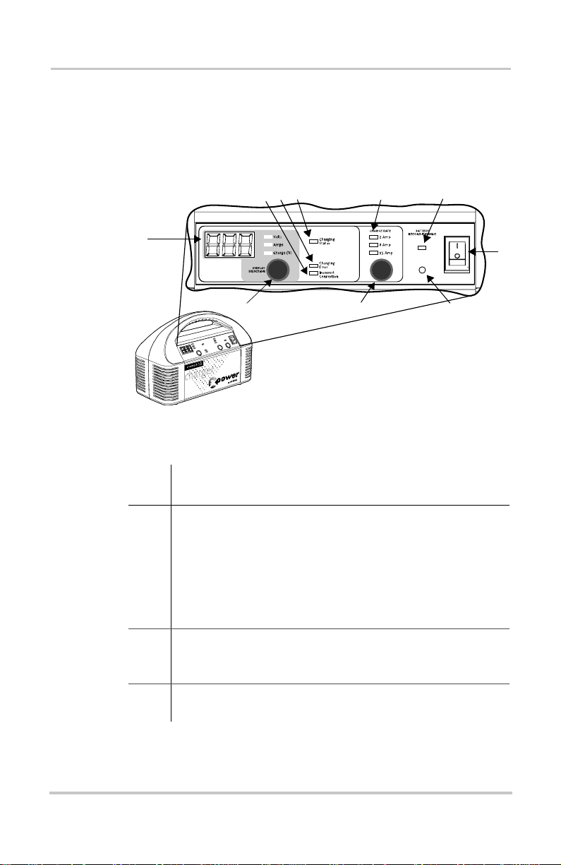
Front Panel I ndicator Lights and Settings
This section describes the parts of the XPower Charger.
Figure 1-1 shows the front panel. Descriptions are provided
in the table.
34
2
1
10
Figure 1-1
Panel
Item Description
1 Digital Display displays the numerical value of the
2 Incorrect Connection l ight, under the Bat tery Charger
3 Charging Error light illuminates when a fault condition
XPower Charger Front Panel
(XPower Charger 15 shown)
battery voltage, charging current and capacity. The
Volts (V), Current (A), Battery % lights indicate which
condition is being reported.
The digital display is also used to indicate error codes
when Charging Error light (Item 6) is illuminated. See
Chapter 3, “Troubleshooting”.
section, illuminates when a revers e polarity is detecte d at
the charging cable.
is detected.
5
9
6
8
7
1-4 975-0147-01-01
Page 15

Front Panel Indicator Lights and Settings
Panel
Item Description
4 Charging Status light indicat es the charging status of the
battery. A blinking light indicates that charging is in
progress. A solid light indicates that the battery is fully
charged.
5 Charge Rate light indicates the selected charging current.
Charge rat e ca n be selected by pushing the Charge Rate
button (Item 12).
6 Battery Reconditioning light in dicates that the battery
reconditioning function is ac tivated. A blinking light
indicate s that the battery reconditioning process is in
progress. A solid light indic ates that the battery
reconditioning process is finished.
7AC power
ON/OFF switch
8 Battery Reconditioning push button (pin hole type)
allows you to recondition a bad flooded battery that is not
acceptin g ch arge (see Item 9).
9 Charge Rate push button al lows you to se lect the opt im al
charge current for your ba ttery (see Item 8).
10 Display Select ion pus h button allows you to to ggle
between the battery voltage and charging current during
battery charging (see Item 4). It also indicates battery
capacity when the unit is not connected to an AC standard
wall outlet.
975-0147-01-01 1-5
Page 16

Charger Cable Storage Compartment
ERROR
CHARGING
ERROR
Battery is not accepting charge or
BAD BATTER Y SHUTDOWN
battery charge rate is low
OVERVOLTAGE
Battery model being charged is
18V or above
HIGH CURRENT S HU TDOWN
High current load is connected to
the battery
Unit is overheated due to poor
OVER HEAT SHU TDOWN
ventilation
CHARGING TIME OFF
Charging time reached 24 hours • Check load is connected to battery
PO SSI BLE C AUSE REC OMM ENDA TIO N
• Selec t a higher charge r ate
•For flooded battery, activate the battery
reconditioning feature (see Owner's Guide)
• Check battery being connected. XPower will
recharge 12V batteries only. Use
appropriate charger for your battery.
• Remove all loads from battery being
charged.
• Ensure vent openings are not obstructed.
Unit will automatically reset.
•Select higher charge rate
• Battery has damaged cells and cannot be
charged. Replace battery.
CODE
EO1
EO2
EO3
EO4
EO5
2
4
1
3
Figure 1-2
XPower Charger Storage Compartment
(XPower Charger 15 shown)
Panel
Item Description
1 Battery Ch arging Clips for charging your vehicle
battery.
2 Storage Compartment for AC cable and battery clips.
3 Error Code Reference Table provides quick battery
troubleshooting.
4 AC Cable c onnects the XP ower Charger to the AC wall
socket.
1-6
Page 17

2
Operating Conditions and Guidelines
Operation
Chapter 2 explains how to operate the XPower Charger
efficiently to charge a vehicl e bat te ry.
CAUTION
Read all ope rating instructions before operating the XPower
Charger.
2-1
Page 18

Choo sing a Lo c ation
WARN ING: Fire or explosion
The XPower Charger contains components that tend to produce
arcs or sparks. To prevent fire or explosion, do not operate the
XPower Charger in compartmen ts containing flammable mate rials,
or in locations that require ignition-protected equipment.
The XPower Charger should be operated only in a location
that meets thes e requ i rem ent s :
Dry
Cool
Ventilated
Safe
Protected
from battery
gases
Do not allow water or other liquids to drop or splash on the
XPower Charger.
Ambient air temperature should be between 32 an d 104ºF
(0 and 40ºC)—the cooler the better within thi s range.
Leave at least 2" (5 cm) clearance around the XPower
Charger for air flow. Ensure that the ventilation openings
are not obstructed.
Do not operate the unit in any compartment capable of
storing flamma ble liquids li ke gasoline.
Do not operate the XPower Charger where it will be
exposed to batte ry gas es. These gases are very corrosive,
and prolonged exposure will damage the XPower Charger.
2-2 975-0147-01-01
Page 19

Charging 12 Volt Batteries
Before you start to charge batteries read the “Important
Safety Instr uctions” on page v and tak e all safety preca utions
when working with batteries .
The XPower Charger has been designed to provide fully
automatic rec h arge of 12 V, automo ti ve , ma rine , deep -c y cl e,
AGM and gell cell batteries.
WARNING: Explosion hazard
The XPower Charge r 15 and 40 are des igned to charge 12 V leadacid batter ies only. Do not use these prod ucts on batteries with
other voltage ratings.
To charge your 12 volt battery:
1. If possible, disconnect all loads from the battery, by
removing battery cables, opening a disconnect switch, or
switching loads off.
The charger detects a battery is fully charged when its
charging current drops below a preset limit. The presence
of electrical loads on the battery may interfere with this
detection method. The 24-hour timer-based char ging
shutdown feature acts as a backup, but the charging
current- based method is preferable.
Charging 12 Volt Batteries
2. Apply AC power to the XPower Charger, turn the AC
power
3. Connect the red positive (+) clip of the charger cabl es to
the positive (+) terminal of the vehicle battery.
The battery’s positive terminal is usually la rger in
diameter than the ne gative te rminal. In most vehicle s, the
battery’s positive terminal has a red wire connected to it.
4. Connect the black negative (–) clip of the charger cabl es
to the negative (–) battery terminal.
If the red Incorrect connection indicator light on the
975-0147-01-01 2-3
ON/OFF switch to ON.
Page 20

Battery Charge r function illumina tes, reverse pola rity has
been detected. Correct polarity must be established
before proceeding. Go back to Step 3.
5. The Charge Rate indicator light will blink. Select the
suitable charging current for your battery (see Table 2-3
or Ta ble 2-4 on page 2-5) by toggling the Char ge Rate
push button located below the indicator light. If the
charging curre nt is not se lect ed with in 10 sec onds , the
unit will set to a default char ge rate of 2 A.
6. The Charging Status indicator light on the Battery
Charger function section will blink and the fullyautomatic charging sequence begins.
7. During charging, the charging curr ent can be set to a
different charge rate or terminated at any time by
toggling the Char ge Rate push button.
XPower Charger 15
0 2815
XPower Charger 40
0 22040
8. During charging, you can toggle the Display Select ion
push button to show either the charging voltage or the
charging current on the Digital Display.
9. When the charging process is complete, the Charging
Status indicator light on the Battery Charger function
section changes from blin king to solid.
A 24-hour timer is built into the unit to avoid battery
overcharging.
The charger will automatically recharge the ba ttery if the
charge current rises above the threshold specified in
T able 2-1 and Table 2-2.
2-4 975-0147-01-01
Page 21

Charging 12 Volt Batteries
Table 2-1
Char gi ng R ate Thr esho ld
Table 2-2
Char gi ng R ate Thr esho ld
XPower Charger 15
2 A 0.6
8 A 1.5
15 A 2.0
XPower Charger 40
2 A 0.6
20 A 3.0
40 A 6.0
10. Turn the AC power ON/OFF switch to OFF.
11. Remove the black negative (–) clip and the red positive
(+) clip from the vehicle’s battery terminals.
12. Store the charging cables in the storage compartment at
the back of the unit.
Charging Rates Selection Guide
Use Table 2-3 a nd Table 2-4 to determine the charging rate.
Table 2-3
Char gi ng R ate
Table 2-4
Char gi ng R ate
975-0147-01-01 2-5
XPower Charger 15
Recommen ded
Battery Size
2 A 6 Ah or above
8 A 20 Ah or above
15 A 40 Ah or above
XPower Charger 40
Recommen ded
Battery Size
2 A 6 Ah or above
20 A 50 Ah or above
40 A 100 Ah or above
Page 22

Reconditioning (Equalizing) Flooded Type
Batteries
WARNING: Explosion hazard
Battery reconditioning featu r e works only on flooded lead-acid
batteries. Do not attempt to recondition sealed lead-acid batteries.
WARNING: Explosion hazard
During the ba ttery reconditioning process, the battery generates
potentially flammable gases. Follow all the battery safety
precautions l ist ed i n this gu ide. Ventilat e the ar ea aro und t he bat tery
thoroughly and ensure that there are no sources of flame or sparks
in the vicinity.
CAUTION
Turn off or disconnect all loads on the battery during
reconditioning. The voltage applied to the battery during
recondition ing ma y be abo ve the safe le vels for some loa ds. Be sur e
to check battery el ec trolyte before and after reconditioning. Fill
only with distilled water.
Important:
timing limit.
To recondi tio n y our ba tt eri es (on the vehicle):
1. Disconnect all loads from the battery by removing
battery cables or by opening a disconnect switch.
2. Apply AC power to the XPower Charger, and turn the
AC power
3. Connect the red positive (+) clip of the cables to the
positive (+) terminal of the engine battery.
The battery’s positive terminal is usually la rger in
diameter than the ne gative te rminal. In most vehicle s, the
battery’s positive terminal has a red wire connected to it.
2-6 975-0147-01-01
The battery reconditioning mode has a 4 hour
ON/OFF switch to ON.
Page 23

Reconditioning (Equalizing) Flooded Type Batteries
4. Connect the black negative (–) clip of the cables to the
negative (–) batter y termi nal.
If the red Incorrect Connect ion indicator light on the
Battery Charge r function illumina tes, reverse pola rity has
been detected. Correct polarity must be established
before proceeding.
5. Use a toothpick, paper clip, pen point or other small
object to push the Battery Recondi tioning button
(pin-hole type).
6. The Battery Reconditioning a nd Charge Rate indicator
lights illuminat e and blink.
The display shows ( _ _ _ ) then ( – – – ) then ( ).
7. Select the suitable battery reconditioning current for the
battery size (see Table 2-3 or Tabl e 2-4 on page 2-5) by
pushing the Charge Rate push button.
If the bat tery r econdi tioning c urrent is not se lect ed withi n
10 seconds, the unit will set to a default charging rate of
2A.
8. Monitor the specific gravity of each cell of the battery
during reconditi oning with a battery hydrometer.
Reconditioning is complete when the specific gravity of
each cell of the battery remains constant. Most lead-acid
batteries have a specific gravity of approximately 1.265
when fully charge d.
When the battery reaches the target specific gravity, press
the Charge Rate butto n until all charge rate lights are off
or remove the battery clips to terminate the
reconditioning mode.
9. If the specific gravity is still rising when the
reconditioning mode reaches the 4 hour timing limit, you
can initiate furthe r reconditi oning by pre ssing the Batter y
Reconditioning button again.
After approximately 4 hours, the Battery Reconditioning
indicator light change s from blinking to solid and the
digital display will show ( ).
The battery reconditioning mode has been terminated.
975-0147-01-01 2-7
Page 24

10. Turn the AC power ON/OFF switch to OFF.
11. Remove the black negative (–) clip and the red positive
(+) clip from the vehicle’s battery terminals.
12. Check the battery electrolyte level. If necessary, refill
with distilled water only.
2-8 975-0147-01-01
Page 25

3
Troubleshooting
Chapter 3 will help you identify and remedy the common
problems than can occur with the XPower Charger.
Read this chapter before calling Customer Service.
If you cannot solve the problem with the XPower Charger,
record the inf ormation aske d for on “Inform ation About Your
System” on page WA–6 and then call Customer Service.
Troubleshooting Reference
WARN ING: Electric shock hazard
Do not disassemble the XPower Charger. The XPower Cha rger
does not contain any internal user-serviceable parts and attempting
to service the unit yourself could result in electrical shock or burn.
Page 26

Table 3-1
Troubleshooting reference
Problem Possib l e Ca us e Solution
Digital
Display or
LED
on unit does
not turn on
Digital
Display shows
voltage and
charging
current but not
Charge %
during
charging
Digital
Display shows
Charge % but
not voltage
and charging
current
Digital disp lay
always shows
0 when the
battery is
connected
No power at the AC
receptacle
AC Power
is
OFF
ON/OFF switch
Unit is normal, as the
charge % reading is
disabled when unit is
charging a battery
Unit is normal. With no
AC connected to the unit,
the digital display will
only show bat tery capaci ty
(in %) when it is
connected
The battery bei ng ch arged
is below 2.5 VDC
Poor connection on
battery termi nals
Ensure that power is available at
the receptacle
Ensure AC Power
is
ON
ON/OFF switch
Battery cannot be charged
Check battery conn ec tions
The red Incorrect
Connection indicator light
is illu minated indi ca ting
that the positive and
Reconnect the char ger cable
clips to the correct polarity (see
“T o char ge y our 12 v olt ba ttery: ”
on pa ge 2-3)
negative charging cable
clips ar e rev er sed
3-2 975-0147-01-01
Page 27

Troubleshooting Reference
Table 3-1
Problem Possib l e Ca us e Solution
Charging
Error E01
Bad Battery
Shutdown
Charging
Error E02
Overcharge
Shutdown
Charging
Error E03
High Current
Shutdown
Charging
Error E04
Overheat
Shutdown
Troubleshooting reference
Battery is not ac cepting
charge
Charging rate selected is
too low for the battery
being charged
Battery model being
charged is 18 V or above
High current load is
connected to the battery
Unit has ov erheat ed due to
poor ventilation or
excessivel y warm
environmental conditions
For flooded battery, try
reconditioning the battery (see
“To recondition your batteries
(on the vehicle):” on pag e 2-6)
Select a higher c harge rate (see
Table 2-3 or Table 2-3 on
page 2-5)
Check battery being connected.
This charger will recharge 12 V
batteries only. Use appropriate
charger for your battery
Remo v e all loads fro m th e
battery being charged
Clear blocked ventilation
openings or remove object s
covering the unit. Unit will
automatically restart when it
cools down
Move the XPower Char ger to a
cooler environment
Charging
Error E05
Charging T ime
Off
975-0147-01-01 3-3
Battery charging time
reaches 24 hours
Charging rate selected for
battery charg ing is too low
for the battery being
charged
Battery has a damaged cell
Check load is connect ed to
battery
Select a h igher char ging rate (se e
Table 2-3 or Table 2-3 on
page 2-5)
Replace battery
Page 28

3-4
Page 29

A
Specifications
Appendix A lists the specific ations for the XPower Charger.
Important:
Specificati ons are subject to change without notice.
Physica l Specifications
\
Dimensions
• XPower Charger 15
• XPower Charger 40
Weight
• XPower Charger 15
• XPower Charger 40
AC Input Connections
• XPower Charger 15
• XPower Charger 40
DC Output Connections
XPower Charger 15
XPower Charger 40
270 mm x 130 mm x 180 mm
(10.63 in. x 5.12 in. x 7.09 in.)
295 mm x 143 mm x 202 mm
(11.61 in. x 5.63 in. x 7.95 in.)
1.94 kg (4 .28 lb s )
3.54 kg (7 .8 lbs)
6.5’ (2.0 m) AWG 18
6.5’ (2.0 m) AWG 16
6.0’ (1.8 m) AWG 14
6.0’ (1.8 m) AWG 10
A-1
Page 30

Electric al Specifications
Battery Charging S ystem
\
Number of Battery Bank Outputs 1
Nominal Battery Voltage 12 VDC
Nominal Operating Output Range 2.5 – 15.6 VDC
Rated DC Output Current
• XPower Charger 15
• XPower Charger 40
Charg e M o d es 3 stage
Absorption Voltage 14.4 VDC
Float Voltage at no Load 13.6 VDC
Battery Reconditioning Mode
\
Maximum Output Voltage 16.5 VDC
Battery Reconditioning Mode
Current
• XPower Charger 15
• XPower Charger 40
2/8/15 ADC
2/20/40 ADC
0.25 A with 2 A settin g
1.0A with 8A setting
2.0 A with 15 A setting
0.25 A with 2 A settin g
2.5 A with 20 A setting
5.0 A with 40 A setting
A-2 975-0147-01-01
Page 31

AC Input Specifications
AC Input Specific ations
\
XPower Charger 15 XPower Charger 40
AC Input Voltage Range 104 – 127 VAC, 50/60 Hz
Typical AC Input Current at
120 VAC
No-load AC Power Draw Less than 3 watts
Power Factor Rated Load 0.66 0. 68
Efficiency – peak 83%
3.5 A RMS 8.5 A RMS
Protection Features
\
Battery Reverse Pola rity Reverse Polarity indicator light on charger
section of front panel illuminates
Output Current Limit
• XPower Charger 15
• XPower Charger 40
Error Code with Light
ON E01 — E05
2A — 2.1A
8A — 8.4A
15 A — 15.8 A
2A — 2.1A
20 A — 21 A
40 A — 42 A
Approvals
\
Product Safety ETL approved to CSA107.2 and UL 1236
standards
Electromagnetic Compatibility
(EMC)
975-0147-01-01 A-3
Complies with FCC part 15B, Class B
Page 32

A-4
Page 33

B
Battery Charging
Appendix B describes battery charging in more detail.
XPower Charger charges batteries in a sequence known as a
three-stage charge. The charging voltage delivered to the
battery depends on the batte ry
The three automatic stages are:
• bulk
• absorption
•float
There is a fourth stage, battery recondition (equalization),
that is initialized manually since it is only performed
occasionally and only on a floode d battery .
Bulk Charge
In the fir st stage, k nown as the bulk charge, XPower Charger
delivers its full - rated output current.This consta nt current is
delivered to the ba tteries until the bat tery voltage approaches
its absorpti on voltage—typically around 14.5 volts. The bulk
charge stage restores about 75% of the battery’s charge.
Absorption Cha rge
During the absorption charge, the charging voltage is held
constant near the gassing voltage, and the battery graduall y
reduces the char ging cu rrent it demands as it attains full
charge. Once the current drops to around 1/6 of the charging
current in bulk charge mode, the c harger exits to Float charge
mode.
B-1
Page 34

Float Charge
The float charge is a maint enance mode in which the output
voltage of the charger is reduced to a lower level, typically
about 13.5 volts to maintain the battery’ s charge without
losing electrolyte through gassing. In the float mode, the
charger will initiate a new charge cycle under any of these
conditions:
• AC power is disconnected and reconnected
• current demand on char ger exce eds the battery recharge
current setting
The chart in Figure B-1 shows the three-stage charging
profile.
Charging started
DC Voltage
DC Current
Time
Figure B-1
Bulk stage Absorption
stage
Constant voltage
at Absorpt i on
voltage setting
Constant current
at maximum
charge rate
Three-stage charging profile
Float stage
Constant vo ltag e
at the Float
voltage setting
Load current on demand
B-2
Page 35

Calculating External Batte ry Charging Time
Calculating External Battery Charging Time
Formula
Charging time will depend on the capacity of your battery
and on how deeply it is discharg ed. The following equation
calculates an appr o xim ate ch arg ing tim e:
Charging time = CA P x DO D
CC x 80%
where:
Charging Time: Battery recharge time in hour s
CAP: Battery capacity in amp-hours
DOD: Battery depth of discharge in per cent. A fully
discharged batte ry has 100% DOD
CC: Charge current, the rat ed current output of the
charger in amperes
80%: Typical charging efficiency for lead-acid batteries
Example
A Group 27 size battery rated at 82 amp-hours is 40%
discharge d, tha t is, it has a DOD = 40. Charging time with a
XPower Charger unit is cal culated as follows:
Charging time = 82 Ah x 40% = 2 hours
20 A x 80%
975-0147-01-01 B-3
Page 36

Battery Reconditioning Mode
A battery rec onditioning charge should be performed only on
vented, flooded (non-sealed or “wet”) batteries. It should be
performed only if recommended by the battery manufacturer
and only as often as specified. Battery reconditioning is a
deliberate overc harge designe d to return each cell to opti mum
condition by reducing sul fation and stratification in the
battery. The overcharge helps the battery to reach and
maintain peak capacity by equalizing the chemistry in the
individual battery cells.
CAUTION: Risk of battery damage
XPower Charger cannot automatically determine when to stop the
reconditioning of a battery. You must monitor the battery specific
gravity thr oughout reconditioning to determine the end of the
reconditioning cycle. The 4 hour time-out is intended as a safety
feature but may not be sufficiently short to prevent battery damage.
WARNING
Do not recondition gel cell batteries.
WARNING
Always monitor the reconditioning charge cycle. Provide pr oper
ventilation for battery fumes. Do not allow any sparks during
recondition ing. If one or more cells beg in to overflow, terminate the
recondition cycle.
WARNING
Check the batt ery electrolyte both before and after the
recondition ing cha r ge. Do not ex pose the batte ry pl ates to ai r . Leav e
the battery caps on while reconditioning. Top off after
reconditioning.
WARNING
Remove all load s from the DC system before reconditioning. Some
DC loads may not tolerate the high charge voltage.
B-4 975-0147-01-01
Page 37

About Reconditioning
Frequency
Approximately once a month, you may wish to recondition
your flooded batteri es by using the battery reconditioning
mode.
Important
Reconditioning can damage your batteries if it is not
performed properly. Never recondition a battery more than
twice a month. Always check battery fluid level before and
after reconditioning. Fill batteries only with distilled water.
Battery manufactur ers' recommendations on reconditi oning
vary. Always follow the battery manufacturer's instructions
so batteries are proper ly reconditioned. As a guide, a heavily
used battery may require reconditionin g once a month while a
battery in light duty se rvice, only needs reconditioning every
two to four months. XPower Charger provides a high-quality
charge so batteries will not need to be reconditioned as often
as with a lower quality char ger.
Battery type
Battery Reconditioning Mode
XPower Charger reconditions only flooded lead-acid
batteries. It does not recondition sealed lead-acid batteries
since they can be damaged by this process.
Duration
Reconditioning is manually terminated when the specific
gravity in each cell is about 1.265 and rema ins constant at
that level. XPower Charger automatically exits the
reconditioning mode afte r six hours.
Battery charge state
Reconditioning is only performed on fully-charged batteries.
If they are not charged, the first part of the process is similar
to the absorption charge and ensures the battery is fully
charged.
Recommended
The manufacturer recommends tha t you run a normal charge
cycle on the batteries bef ore you rec ondition them.
975-0147-01-01 B-5
Page 38

B-6
Page 39

Warranty and R etu rn
Information
Warranty
What does this warranty cover? This Limited Warranty is provided by Xantrex Technolog y, Inc. ("Xantrex") and covers defects in workmanship and materials in your XPower Charger 15 and 40. This warranty period lasts for 12 mon ths from the date of purchase at the point of sale to you, the original end user customer. You require proof of purchase to make warranty claims.
What will Xantrex do? Xantrex will, at its option, repair or re place the defective product free of char ge, provided that you notify Xantrex of the product defect within the Warrant y Period, and provided that Xa ntrex throug h inspection establishes the existence of such a defect and that it is covered by this Limited Warranty.
Xantrex will, at its option, use new and/or reconditioned parts in performing warranty
repair and building replacement products. X antrex reserves the right to use part s or
products of original or improved design in the repair or replacement. If Xantrex repairs or
replaces a product, its warrant y continues for the remaining porti on of the original
Warrant y P eriod or 90 days fr om the date of the return shipment to the customer,
whichever is greater. All replaced products and all parts rem oved from repa ired products
become the property of Xantrex.
Xantrex covers bot h p arts and labo r nec ess ary t o re pai r the pr oduct, an d ret urn shi pmen t to
the customer via a Xantrex-selected non-expedited surface freight within the contiguous
United States and Ca nada. Alaska and Hawaii are excluded . Contact Xantrex Custom er
Servic e for details on freight policy for return shipments outside of the conti guous United
States and Canada.
How do you get service? If your product requires troubleshooting or warranty serv ice, contac t your merchant. If you are una ble to contact your merchant, or the merchant is unable t o provide service, contact Xantrex directly at:
Telephone: 1 800 670 0707 (toll free North America)
1 360 925 5097 (direct)
Fax: 1 800 994 7828 (toll free North America)
1 360 925 5143 (direct)
Email: customerservice@xantrex.com
Direct returns may be performed accord ing to the Xant rex Return Mat erial Author ization
Policy des cr ibed i n you r p roduct manu al . For s ome pr odu ct s, Xant r ex mai ntai ns a networ k
of regional Authorized Service Centers. Call Xan trex or check our w ebsite to see if your
product can be repaired at one of these facilities.
WA-1
Page 40

Warranty and Return
What proof of purchase is required? In any warran ty claim, dated proof of purcha se must accompany the product and the product must not have been disassembled or modifie d without prior written au thorization by Xantrex.
Proof of pu rchase may be in any one of the foll ow ing forms:
• The dated purc hase re cei pt from the ori gi nal purc has e of the prod uct at po int of sal e to
the end use r, or
• The dated dealer invoice or purchase receipt showing original equipment
manufacturer (OEM) status, or
• The dated invoice or purchase recei pt showing the pr oduct exchanged under warranty
What does this warranty not cover? This Limited Warranty does not cover normal wear and te ar of t he produc t o r c osts rel ated to th e rem oval, i nstal la tion , o r tro ubl eshoot i ng of the customer's electrica l systems. This warranty does not apply to and Xantrex will not be respon sible for any defect in or dam age to:
a) the product if it has been misused, neglected, improperly installed, phys ically
damaged or altered, either internally or externally, or damaged from im proper use or
use in an unsuitable envi ronment;
b) the product if it has been subjecte d to fire, water, generalized corrosion, bi ological
infestat i ons, o r input vol tage th at crea te s oper at ing condi ti ons b eyon d t he maxim um or
minim um limits liste d in th e X an tr ex produc t sp ec if ication s in cl u di ng hi gh in pu t v ol tage from generators and lightning strikes;
c) the product if repairs have been done to it other than by Xantrex or its authorized ser-
vice centers (hereafter “ASCs”);
d) the product if it is used as a component part of a product expressly warranted by
another ma nufacturer;
e) th e product if its original id entifica ti o n (tr ade-mar k, serial numb er) markin g s ha v e
been defaced, altered, or removed.
WA-2 975-0147-01-01
Page 41

Warranty and Return
Disclaimer
Product
THIS LIMITED W ARRANTY IS THE SOLE AND EXCLUSIVE WARRANTY PROVIDED BY
XANTREX IN CONNECTION WITH YOUR XANTREX PRODUCT AND IS, WHERE
PERMITTED BY LAW, IN LIEU OF ALL OTHER W AR RANTIES, CONDITIONS,
GUARANTEES, REPRESENTATIONS, OBLIGATIONS AND LIABILITIES, EXPRESS OR
IMPLIED, STATUTORY OR OTHERWISE IN CONNECTION WITH THE PRODUCT,
HOWEVER ARISING (WHETHER BY CONTRACT, T ORT, NEGLIGENCE, PRINCIPLES OF
MANUFACTURER'S LIABILITY, OPERATION OF LAW, CONDUCT, STATEMENT OR
OTHERWISE), INCLUDING WITHOUT RESTRICTION ANY IMPLIED WARRANTY OR
CONDITION OF QUALITY, MERCHANTABILITY OR FITNESS FOR A PARTICULAR
PURPOSE. ANY IMPLIED WARRANTY OF MERCHANTABILITY OR FITNESS FOR A
PARTICULAR PURPOSE TO THE EXTENT REQUIRED UNDER APPLICABLE LAW TO
APPLY TO THE PRODUCT SHALL BE LIMITED IN DURATION TO THE PERIOD
STIPULATED UNDER THIS LIMITED WARRANTY.
IN NO EVENT WILL XANTREX BE LIABLE FOR ANY SPECIAL, DIRECT, INDIRECT,
INCIDENT AL OR CONSEQUENTIAL DAMAGES, LOSSES, COSTS OR EXPENSES
HOWEVER ARISING WHETHER IN CONTRACT OR TORT INCLUDING WITHOUT
RESTRICTION ANY ECONOMIC LOSSES OF ANY KIND, ANY LOSS OR DAMAGE TO
PROPERTY, ANY PERSONAL INJURY, ANY DAMAGE OR INJURY ARISING FROM OR AS
A RESULT OF MISUSE OR ABUSE, OR THE INCORRECT INSTALLATION, INTEGRATION
OR OPERATION OF THE PRODUCT.
Exclusions
If this product is a consumer product, federal law does not allow an exclusion of implied
warranties. To the extent you are entitled to implied warranties under federal law, to the
extent permitted by applicable law they are limited to the duration of this Limited
Warrant y. Some states and provinces do not al low limitations or exclusions on impli ed
warranties or on the duration of an implied warranty or on the limitation or excl usion of
incidental or consequential dam ages, so the above limitation(s) or exclusion(s) may not
apply to you. This Limited Warranty gives you specific legal rights. You may have other
rights w hich may vary from state to state or province to province.
Warning: Limitations On Use
Please refer to your product manual for limitations on uses of the product.
SPECIFICAL LY, PLEAS E N OTE TH AT THE XPOWER CHARGER 15 AND 40 SHOULD
NOT BE USED IN CONNECTION WITH LIFE SUPPORT SYSTEMS OR OTHER MEDICAL
EQUIPMENT OR DEVICES. WITHOUT LIMITING THE GENERALITY OF THE FOREGOING ,
XANTREX MAKES NO REPRESENTATIONS OR WARRANTIES REGARDING THE USE OF
THE XANTREX
SYSTEMS OR OTHER MEDICAL EQUIPMENT OR DEVICES.
975-0147-01-01 WA-3
XPOWER CHARGER 15 AND 40 IN CONNECTION WITH LIFE SUPPORT
Page 42

Warranty and Return
Return Material Authorization Policy
Before returning a product directly to Xantrex you m u st obtain a Return Material
Authori zation (RMA) num ber and the correct factory "Ship To" address. Products must
also be shipp ed pr epa id. Pr oduc t shipme nt s wil l be ref used and ret urn ed at your expe nse if
they are unauthorized, returned without an RMA num b er clearly marked on the outside o f
the shipping box, if they are shipped collect, or if they are shippe d to the wrong location.
When you contact Xantrex to obtain service, please have your instruction manual ready
for reference and be prepa re d to su pp ly:
• The seri al number of your product
• Information about the inst allation and use of the unit
• Information about the failure and/or reason f o r the return
• A copy of your dated proof of purchase
Record these details in “Informa tion About Your System” on pageWA-6.
Return Procedure
1. Package the unit safely , preferably using the original box and pa cking materia ls.
Please ensure that your product is shipped full y insured in the original pack aging or
equivalent. This warranty will not apply where the product is dam aged due to
improper packaging.
2. Include the fol lowing:
• The RMA number supplied by Xantrex Technology, Inc. clearly mar ked on the
outside of the box.
• A return address where the unit can be shipped. Post office boxes are not
acceptable.
• A contact telephone number where you can be reached during work hours.
• A brief des cription of the problem.
3. Ship the unit prepaid to the address provided by your Xantrex customer service
representative.
If you ar e returning a product from outside of the US A or C anada In addition to the above, you M UST in clude r et urn fr ei ght fun ds a nd ar e ful ly r espons ib le for al l docum ents , duties, tariffs, and deposits.
If you are returning a product to a Xant rex Authorized Service Center (ASC) A Xantrex return material authorization (RMA) number is not required. However, you must contac t the ASC prior to re turning the product or presenting the unit to verify any return procedu res that may apply to that particular facility.
WA-4 975-0147-01-01
Page 43

Warranty and Return
Out of Warranty Service
If the warranty period for your XPower Charger 15 and 40 has expired, if the unit was
damaged by misuse or incor rect installation, if other condi tions of the warr anty have not
been met, or if no dated proof of purchase is available, your inverter may be serviced or
replac ed for a flat fee.
To return yo ur X P ower Charger 15 and 40 for out of warranty service, contact Xantrex
Customer Service for a Return Material Authori zation (RMA) nu mber and follow the
other steps outlined in “Return Proce dure” on page WA-4.
Payment opt ions such as credit card or mo ney order will be explaine d by the Customer
Service Represent ative. In cases where the minimum fla t fee does not apply, as with
incomplete units or units with excessive damage, an additional fee will be charged. If
applicable, you will be contacted by Customer Service on ce your unit has been received.
975-0147-01-01 WA-5
Page 44

Warranty and Return
Inform at ion About Your System
As soon as you open your XPower Charger 15 and 40 package, record the foll ow ing
information and be su re to keep your proof of purcha se.
❐ Serial Number (on DC end)
❐ Purchased From
❐ Pu rchase Date
If you need to contact Customer Service, please record the following details before
calling. This inform ation will hel p our representatives give you better service.
❐ Battery/battery bank si ze
❐ DC wiring size and length
_______________________________
_______________________________
_______________________________
_________________________________
_________________________________
❐ Warning, Error or Panel
Fault Message
_________________________________
❐ Appliances operating when
problem occur r ed
❐ Description of problem
______________________________________________________________
______________________________________________________________
_________________________________
_________________________________
WA-6 975-0147-01-01
 Loading...