

Page 1
TM
TM
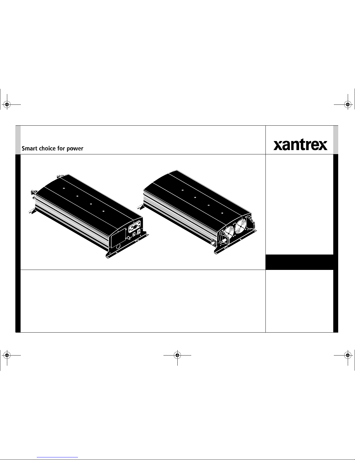
XPower™ Inverter 3000
Owner’s Guide
813-3000-UL
XPower 3000 Inverter Owners Guide.book Page i Friday, April 13, 2018 11:26 AM
Page 2

XPower 3000 Inverter Owners Guide.book Page ii Friday, April 13, 2018 11:26 AM
Page 3
975-0555-01-01 i
Copyright © 2018 Schneider Electric. All Rights Reserved. All trademarks are
owned by Schneider Electric Industries SAS or its affiliated companies.
Exclusion for Documentation
UNLESS SPECIFICALLY AGREED TO IN WRITING, SELLER
(A) MAKES NO WARRANTY AS TO THE ACCURACY, SUFFICIENCY OR SUITABILITY OF ANY
TECHNICAL OR OTHER INFORMATION PROVIDED IN ITS MANUALS OR OTHER DOCUMENTATION;
(
B) ASSUMES NO RESPONSIBILITY OR LIABILITY FOR LOSSES, DAMAGES, COSTS OR EXPENSES,
WHETHER SPECIAL, DIRECT, INDIRECT, CONSEQUENTIAL OR INCIDENTAL, WHICH MIGHT ARISE
OUT OF THE USE OF SUCH INFORMATION. THE USE OF ANY SUCH INFORMATION WILL BE ENTIRELY
AT THE USER’S RISK; AND
(C) REMINDS YOU THAT IF THIS MANUAL IS IN ANY LANGUAGE OTHER THAN ENGLISH,
ALTHOUGH STEPS HAVE BEEN TAKEN TO MAINTAIN THE ACCURACY OF THE TRANSLATION, THE
ACCURACY CANNOT BE GUARANTEED. APPROVED CONTENT IS CONTAINED WITH THE ENGLISH
LANGUAGE VERSION WHICH IS POSTED AT WWW.XANTREX.COM.
Document Part Number
975-0555-01-01
Date and Revision
April 2018 Rev C
Product Part Number
813-3000-UL
Contact Information
Information About Your System
As soon as you open your product, record the following information and be sure to
keep your proof of purchase.
To view, download, or print the latest revision, visit the website shown under Contact
Information.
Telephone: +1 800 670 0707
+1 408 987 6030
Web: www.xantrex.com
Email: customerservice@xantrex.com
Serial Number
_________________________________
Product Number
_________________________________
Purchased From
_________________________________
Purchase Date
_________________________________
XPower 3000 Inverter Owners Guide.book Page i Friday, April 13, 2018 11:26 AM
Page 4

ii XPower Inverter 3000 Owner’s Guide
About This Guide
Purpose
The purpose of this Owner’s Guide is to provide explanations and
procedures for operating, maintaining, and troubleshooting the XPower
Inverter 3000.
Scope
The Guide provides safety guidelines, as well as information about
operating and troubleshooting the inverter. It does not provide details about
particular brands of batteries. You need to consult individual battery
manufacturers for this information.
This Guide does not provide installation instructions. Installation should be
handled by qualified installers including licensed technicians and
electricians. Qualified installers have knowledge and experience in
installing electrical equipment, knowledge of the applicable installation
codes, and awareness of the hazards involved in performing electrical work
and how to reduce those hazards.
Qualified installers are to use the XPower Inverter 3000 Installation Guide
(doc. part number: 975-0556-01-01).
Audience
The Guide is intended for users and operators as well as installers of the
XPower Inverter 3000.
Related Information
You can find more information about Xantrex-branded products and
services at www.xantrex.com.
XPower 3000 Inverter Owners Guide.book Page ii Friday, April 13, 2018 11:26 AM
Page 5
975-0555-01-01 iii
Important Safety Instructions
IMPORTANT: READ AND SAVE THIS OWNER’S GUIDE FOR FUTURE
REFERENCE.
This guide contains important safety instructions for the XPower Inverter
3000 that must be followed during operation and troubleshooting.
Read these instructions carefully and look at the equipment to become
familiar with the device before trying to operate, service or maintain it. The
following special messages may appear throughout this bulletin or on the
equipment to warn of potential hazards or to call attention to information
that clarifies or simplifies a procedure.
The addition of either symbol to a “Danger” or “Warning” safety
label indicates that an electrical hazard exists which will result in
personal injury if the instructions are not followed.
This is the safety alert symbol. It is used to alert you to potential
personal injury hazards. Obey all safety messages that follow this
symbol to avoid possible injury or death.
DANGER
DANGER indicates an imminently hazardous situation, which, if not
avoided, will result in death or serious injury.
WARNING
WARNING indicates a potentially hazardous situation, which, if not
avoided, can result in death or serious injury.
CAUTION
CAUTION indicates a potentially hazardous situation, which, if not
avoided, can result in moderate or minor injury.
NOTICE
NOTICE indicates a potentially hazardous situation, which, if not avoided,
can result in equipment damage.
Important: These notes describe things which are important for you to
know, however, they are not as serious as a caution or warning.
XPower 3000 Inverter Owners Guide.book Page iii Friday, April 13, 2018 11:26 AM
Page 6
iv XPower Inverter 3000 Owner’s Guide
Safety Information
This chapter contains important safety instructions for operating the
XPower Inverter 3000. Each time, before using the XPower Inverter 3000,
READ ALL instructions and cautionary markings on or provided with the
inverter and all appropriate sections of this guide.
NOTE: The XPower Inverter 3000 contains no user-serviceable parts.
NOTE: Turning the inverter to Standby mode using the O
N/STANDBY switch
on the front panel will not reduce an electrical shock hazard.
DANGER
HAZARD OF FIRE, ELECTRIC SHOCK, EXPLOSION, OR ARC FLASH
• Do not expose the inverter to rain, snow, spray, or bilge water. This
inverter is designed for indoor use only.
• Do not operate the inverter if it has received a sharp blow, been
dropped, has cracks or openings in the enclosure including if the fuse
cover has been lost, damaged, or will not close, or otherwise damaged
in any other way.
• Do not disassemble, open, or repair the inverter. Refer all servicing to
qualified service personnel.
• Disconnect both AC and DC power from the inverter before
attempting any maintenance or cleaning or working on any circuits
connected to the inverter. Internal capacitors remain charged after all
power is disconnected.
• Do not operate the inverter with damaged or substandard wiring.
Make sure that all wiring is in good condition and is not undersized.
Failure to follow these instructions will result in death or serious injury.
DANGER
FIRE AND BURN HAZARD
• Do not cover or obstruct the air intake vent openings.
• Do not use transformerless battery chargers in conjunction with the
inverter due to overheating.
Failure to follow these instructions will result in death or serious injury.
DANGER
EXPLOSION HAZARD
• The XPower Inverter 3000 is designed for deep cycle lead-acid
batteries. See warning below when connecting to lithium ion
batteries.
• Do not work in the vicinity of lead-acid batteries. Batteries generate
explosive gases during normal operation. See note #1.
• Do not operate in compartments containing flammable materials or in
locations that require ignition-protected equipment. See notes #2 and
#3.
Failure to follow these instructions will result in death or serious injury.
XPower 3000 Inverter Owners Guide.book Page iv Friday, April 13, 2018 11:26 AM
Page 7
975-0555-01-01 v
NOTES:
1. Follow these instructions and those published by the battery
manufacturer and the manufacturer of any equipment you intend to use
in the vicinity of the battery. Review cautionary markings on these
products and on the engine.
2. This inverter contains components which tend to produce arcs or
sparks.
3. Locations include any space containing gasoline-powered machinery,
fuel tanks, as well as joints, fittings, or other connections between
components of the fuel system.
Precautions When Working With Batteries
NOTES:
1. Locate the XPower Inverter 3000 unit away from batteries in a well
ventilated compartment.
2. Always have someone within range of your voice or close enough to
come to your aid when you work near a lead-acid battery.
3. Always have plenty of fresh water and soap nearby in case battery acid
contacts skin, clothing, or eyes.
4. If battery acid contacts skin or clothing, wash immediately with soap
and water. If acid enters your eye, immediately flood it with running
cold water for at least twenty minutes and get medical attention
immediately.
5. Use extra caution to reduce the risk or dropping a metal tool on the
battery. It could spark or short circuit the battery or other electrical
parts and could cause an explosion.
WARNING
LITHIUM ION BATTERY TYPE HAZARD
Make sure to use a lithium ion battery pack that includes a certified
Battery Management System (BMS) with built-in safety protocols.
Follow the instructions published by the battery manufacturer.
Failure to follow these instructions can result in death or serious injury.
WARNING
BURN FROM HIGH SHORT-CIRCUIT CURRENT, FIRE AND EXPLOSION
FROM VENTED GASES HAZARDS
• Always wear proper, non-absorbent gloves, complete eye protection,
and clothing protection. Avoid touching your eyes and wiping your
forehead while working near batteries. See note #4.
• Remove all personal metal items, like rings, bracelets, and watches
when working with batteries. See notes #5 and #6 below.
• Never smoke or allow a spark or flame near the engine or batteries.
Failure to follow these instructions can result in death or serious injury.
XPower 3000 Inverter Owners Guide.book Page v Friday, April 13, 2018 11:26 AM
Page 8

vi XPower Inverter 3000 Owner’s Guide
6. Batteries can produce a short circuit current high enough to weld a ring
or metal bracelet or the like to the battery terminal, causing a severe
burn.
7. When removing a battery, always remove the negative terminal from
the battery first for systems with grounded negative. If it is grounded
positive, remove the positive terminal first. Make sure all loads
connected to the battery and all accessories are off so you don’t cause
an arc.
Precautions When Placing the Inverter
Regulatory
The XPower Inverter 3000 is certified to UL458 and CSA 107.1 standard.
For more information see “Regulatory Approvals” on page 18.
The XPower Inverter 3000 is intended to be used for mobile or commercial
applications. It is not intended for use in marine and other applications as it
may not comply with the additional safety code requirements needed for
those applications. See “Limitations On Use” below.
The XPower Inverter 3000 includes a “Floating Neutral” AC output design.
It may be permanently damaged if the AC output Neutral is bonded to
Ground which is common in distribution panels. Such damage voids the
warranty.
The XPower Inverter 3000 provides a non-sinusoidal (that is, modified sine
wave) AC output. For more information, see “Inverter Loads” on page 7.
NOTICE
RISK OF DAMAGE TO THE INVERTER
• Never allow battery acid to drip on the inverter when reading gravity,
or filling battery.
• Never place the XPower Inverter 3000 unit directly above batteries;
gases from a battery will corrode and damage the inverter.
• Do not place a battery on top of the inverter.
Failure to follow these instructions can result in equipment damage.
WARNING
LIMITATION ON USE
• Do not use in connection with life support systems or other medical
equipment or devices.
• Do not use in ambulances or other life-saving emergency vehicles.
Failure to follow these instructions can result in death or serious injury.
XPower 3000 Inverter Owners Guide.book Page vi Friday, April 13, 2018 11:26 AM
Page 9

Important Safety Instructions
. . . . . . . . . . . . . . . . . . . . . . . . . . . . . . . . . . . . . . . . . . . . . . . . . . . . . . . . . . . . . . . . . . . . . . . . . . . . . . . . . . . . iii
Introduction . . . . . . . . . . . . . . . . . . . . . . . . . . . . . . . . . . . . . . . . . . . . . . . . . . . . . . . . . . . . . . . . . . . . . . . . . . . . . . . . . . . . . . . . . . . . . . . . . . . . 1
Quality Power . . . . . . . . . . . . . . . . . . . . . . . . . . . . . . . . . . . . . . . . . . . . . . . . . . . . . . . . . . . . . . . . . . . . . . . . . . . . . . . . . . . . . . . . . .1
Ease of Use . . . . . . . . . . . . . . . . . . . . . . . . . . . . . . . . . . . . . . . . . . . . . . . . . . . . . . . . . . . . . . . . . . . . . . . . . . . . . . . . . . . . . . . . . . . .1
Comprehensive Protection . . . . . . . . . . . . . . . . . . . . . . . . . . . . . . . . . . . . . . . . . . . . . . . . . . . . . . . . . . . . . . . . . . . . . . . . . . . . . . . . .1
Inverter Materials List . . . . . . . . . . . . . . . . . . . . . . . . . . . . . . . . . . . . . . . . . . . . . . . . . . . . . . . . . . . . . . . . . . . . . . . . . . . . . . . . . . . .2
Inverter Features . . . . . . . . . . . . . . . . . . . . . . . . . . . . . . . . . . . . . . . . . . . . . . . . . . . . . . . . . . . . . . . . . . . . . . . . . . . . . . . . . . . . . . . . . . . . . . . .3
AC Panel . . . . . . . . . . . . . . . . . . . . . . . . . . . . . . . . . . . . . . . . . . . . . . . . . . . . . . . . . . . . . . . . . . . . . . . . . . . . . . . . . . . . . . . . . . . . . . 3
DC Panel . . . . . . . . . . . . . . . . . . . . . . . . . . . . . . . . . . . . . . . . . . . . . . . . . . . . . . . . . . . . . . . . . . . . . . . . . . . . . . . . . . . . . . . . . . . . . . 4
Inverter Operation . . . . . . . . . . . . . . . . . . . . . . . . . . . . . . . . . . . . . . . . . . . . . . . . . . . . . . . . . . . . . . . . . . . . . . . . . . . . . . . . . . . . . . . . . . . . . . .5
Turning the Inverter On and Standby mode . . . . . . . . . . . . . . . . . . . . . . . . . . . . . . . . . . . . . . . . . . . . . . . . . . . . . . . . . . . . . . . . . . .5
Testing the GFCI . . . . . . . . . . . . . . . . . . . . . . . . . . . . . . . . . . . . . . . . . . . . . . . . . . . . . . . . . . . . . . . . . . . . . . . . . . . . . . . . . . . . . . . .6
Operating Several Loads at Once . . . . . . . . . . . . . . . . . . . . . . . . . . . . . . . . . . . . . . . . . . . . . . . . . . . . . . . . . . . . . . . . . . . . . . . . . . . 6
Operating Limits . . . . . . . . . . . . . . . . . . . . . . . . . . . . . . . . . . . . . . . . . . . . . . . . . . . . . . . . . . . . . . . . . . . . . . . . . . . . . . . . . . . . . . . .6
Inverter Loads . . . . . . . . . . . . . . . . . . . . . . . . . . . . . . . . . . . . . . . . . . . . . . . . . . . . . . . . . . . . . . . . . . . . . . . . . . . . . . . . . . . . . . . . . .7
High Surge Loads . . . . . . . . . . . . . . . . . . . . . . . . . . . . . . . . . . . . . . . . . . . . . . . . . . . . . . . . . . . . . . . . . . . . . . . . . . . . . . . . . . . .7
Trouble Loads . . . . . . . . . . . . . . . . . . . . . . . . . . . . . . . . . . . . . . . . . . . . . . . . . . . . . . . . . . . . . . . . . . . . . . . . . . . . . . . . . . . . . . .7
Connecting Appliances to the Inverter . . . . . . . . . . . . . . . . . . . . . . . . . . . . . . . . . . . . . . . . . . . . . . . . . . . . . . . . . . . . . . . . . . . . . . .8
Routine Maintenance . . . . . . . . . . . . . . . . . . . . . . . . . . . . . . . . . . . . . . . . . . . . . . . . . . . . . . . . . . . . . . . . . . . . . . . . . . . . . . . . . . . . .8
Maintaining the Inverter . . . . . . . . . . . . . . . . . . . . . . . . . . . . . . . . . . . . . . . . . . . . . . . . . . . . . . . . . . . . . . . . . . . . . . . . . . . . . . .8
Testing the GFCI . . . . . . . . . . . . . . . . . . . . . . . . . . . . . . . . . . . . . . . . . . . . . . . . . . . . . . . . . . . . . . . . . . . . . . . . . . . . . . . . . . . .8
Troubleshooting. . . . . . . . . . . . . . . . . . . . . . . . . . . . . . . . . . . . . . . . . . . . . . . . . . . . . . . . . . . . . . . . . . . . . . . . . . . . . . . . . . . . . . . . . . . . . . . . .9
Common Problems . . . . . . . . . . . . . . . . . . . . . . . . . . . . . . . . . . . . . . . . . . . . . . . . . . . . . . . . . . . . . . . . . . . . . . . . . . . . . . . . . . . . . . .9
Contents
XPower 3000 Inverter Owners Guide.book Page i Friday, April 13, 2018 11:26 AM
Page 10

Buzz in Audio Equipment . . . . . . . . . . . . . . . . . . . . . . . . . . . . . . . . . . . . . . . . . . . . . . . . . . . . . . . . . . . . . . . . . . . . . . . . . . . . .9
Television Reception . . . . . . . . . . . . . . . . . . . . . . . . . . . . . . . . . . . . . . . . . . . . . . . . . . . . . . . . . . . . . . . . . . . . . . . . . . . . . . . . .9
Troubleshooting Reference . . . . . . . . . . . . . . . . . . . . . . . . . . . . . . . . . . . . . . . . . . . . . . . . . . . . . . . . . . . . . . . . . . . . . . . . . . . . . . . .9
Specifications . . . . . . . . . . . . . . . . . . . . . . . . . . . . . . . . . . . . . . . . . . . . . . . . . . . . . . . . . . . . . . . . . . . . . . . . . . . . . . . . . . . . . . . . . . . . . . . . .14
XPower 3000 Inverter Owners Guide.book Page ii Friday, April 13, 2018 11:26 AM
Page 11

975-0555-01-01 1
Introduction
The XPower Inverter 3000 has been designed to give you quality power,
ease of use, and reliability.
Please take a few moments to read this chapter to familiarize yourself with
the main performance features and protection features.
Quality Power
The XPower Inverter 3000 is a quality inverter designed for recreational
vehicle (RV) and truck applications.
• The inverter provides up to 2500 watts of continuous power. It is
designed to handle loads such as microwaves, refrigerators, freezers,
circular saws, and small air compressors.
• The inverter’s high surge capability lets you handle many hard-to-start
loads, including large TVs, refrigerators, and freezers.
• The cooling fan in the inverter is thermally activated and comes on
when the inverter becomes warm. The fan turns off automatically after
the inverter has cooled.
Ease of Use
Superior features and rugged durability have been combined with ease of
use:
• The unit is compact, light weight, and easy to install (see XPower
Inverter 3000 Installation Guide (doc. part number: 975-0556-01-01).
• Loads can be powered directly from the GFCI-protected AC outlets.
• Easy-to-read indicators on the front panel let you monitor system
performance at a glance.
• One O
N/STANDBY remote switch with communications cable lets you
control the inverter from a convenient location while the inverter itself
is mounted out of sight.
Comprehensive Protection
The XPower Inverter 3000 is equipped with numerous protection features
to guarantee safe and trouble-free operation:
Low battery alarm Alerts you if the battery has become discharged to
11.0 V or lower.
Low battery voltage shutdown Shuts the inverter down automatically if
the battery voltage drops below 10.5 volts. This feature protects the battery
from being completely discharged.
High battery voltage shutdown Shuts the inverter down automatically if
the input voltage rises to 15 volts or more.
Overload and short-circuit shutdown Shuts the inverter down
automatically if a short circuit is detected in the circuitry connected to the
inverter’s output, or if the loads connected to the inverter exceed the
inverter’s operating limits.
Over temperature shutdown Shuts the inverter down automatically if
its internal temperature rises above an unacceptable level.
XPower 3000 Inverter Owners Guide.book Page 1 Friday, April 13, 2018 11:26 AM
Page 12

2 XPower Inverter 3000 Owner’s Guide
Introduction
Inverter Materials List
The inverter ships with the following items:
• one XPower Inverter 3000 unit,
• owner’s guide,
• one O
N/STANDBY remote switch with communications cable,
• two sets of locks and washers for DC cables,
• one set of rubber boots for DC terminals (not shown), and
• strain-relief clamps for AC input cables (not shown).
NOTE: If any of the items are missing, contact Xantrex or any authorized
Xantrex dealer for replacement. See “Contact Information” on page i.
IMPORTANT:
Keep the carton and packing material in case you need to
return the inverter for servicing.
Figure 1
Materials List
Inverter
with GFCI-protected outlets
Owner’s Guide
ON/STANDBY remote switch with
communications cable
locks and washers
XPower 3000 Inverter Owners Guide.book Page 2 Friday, April 13, 2018 11:26 AM
Page 13

975-0555-01-01 3
Inverter Features
This section describes the different parts of the inverter.
AC Panel
Item Description
1 AC compartment with cover (1a) houses the AC terminal
block for hardwiring the inverter
2 GFCI-protected dual AC outlet
3 AC knockout
Take the cover out when passing cables (wires) through for
hard wiring the inverter.
4 Reset button is used to reset the 20 A supplementary (over-
current) protectors.
5 Power light (green) indicates the inverter is operating.
6 Remote ON/S
TANDBY connector port for connecting the
remote ON/STANDBY switch.
7 Fault light (red) indicates that the inverter has shut down due
to inverter overload or over-temperature.
8 ON/S
TANDBY Switch
Turns the inverter’s control circuit on and on Standby mode.
This switch is not a power disconnect switch. Disconnect AC
and DC power before working on any circuits connected to the
inverter.
9 Remote ON/S
TANDBY Switch comes with 20 feet (6m) long
cable.
Figure 2
AC Panel
REMOTE
POWER
PUISSANCE
FAULT
FAUTE
Non-sin uso id al
output only.
Nonseulement de
sorti e si nuso ïd al e.
3
1
1a
425
6 7 8
9
XPower 3000 Inverter Owners Guide.book Page 3 Friday, April 13, 2018 11:26 AM
Page 14

4 XPower Inverter 3000 Owner’s Guide
Inverter Features
DC Panel
Figure 3
DC Panel
BATT.
NEG.
BATT.
POS.
2
3
1
4
Item Description
1 Negative DC Input Terminal always connects to the
negative terminal of the battery via a negative DC input
cable (black battery cable). The negative DC input
terminal is colored black.
2 Positive DC Input Terminal always connects to the
positive terminal of the battery via a positive DC input
cable (red battery cable). The positive DC input terminal
is colored red.
3 Chassis Ground Screw connects to vehicle chassis, DC
grounding bus or to engine’s negative bus.
4 Ventilation Openings must not be obstructed for the
proper operation of the inverter. When the inverter is
mounted, the ventilation opening on the DC panel must
not point up or down.
XPower 3000 Inverter Owners Guide.book Page 4 Friday, April 13, 2018 11:26 AM
Page 15

975-0555-01-01 5
Inverter Operation
This section explains how to operate the inverter efficiently and effectively:
• Gives procedures for operating the inverter from the front panel
• Discusses operating limits and inverter loads
• Discusses battery charging frequency
• Provides information about routine maintenance
Turning the Inverter ON and S
TANDBY MODE
The ON/STANDBY switch on the inverter’s front panel is the main switch
that turns the control circuit in the inverter on and in Standby mode.
To turn the inverter on and in Standby mode from its front panel:
• Move the O
N/STANDBY switch to the On position to turn the inverter
on.
• Move the O
N/STANDBY switch to the Standby position to turn the
inverter to Standby mode.
When in Standby mode, the inverter draws a very low current from the
battery. See important note below.
To turn the inverter on and in Standby mode from the remote switch:
• Make sure the main O
N/STANDBY switch on the front panel is turned
on.
• Move the remote O
N/STANDBY switch to the On position to turn the
inverter on.
• Move the remote O
N/STANDBY switch to the Standby position to turn
the inverter to Standby mode.
When in Standby mode, the inverter draws a very low current from the
battery.
WARNING
ELECTRICAL SHOCK HAZARD
The inverter’s O
N/STANDBY switch does not disconnect DC battery
power from the inverter. You must disconnect AC and DC power before
working on any circuits connected to the inverter.
Failure to follow these instructions can result in death or serious injury.
IMPORTANT:
The inverter draws less than 300 mA from the battery with
the main ON/STANDBY switch turned on and no load connected. If the main
switch is left on, even with no loads the inverter will eventually discharge
the battery.
To prevent unnecessary battery discharge, turn the inverter to Standby
mode when you are not using it
XPower 3000 Inverter Owners Guide.book Page 5 Friday, April 13, 2018 11:26 AM
Page 16

6 XPower Inverter 3000 Owner’s Guide
Inverter Operation
Testing the GFCI
Perform the following GFCI Test:
1. Turn the inverter on.
2. Plug a simple appliance, such as a lamp, in the GFCI outlet. Turn the
lamp on.
3. Press the TEST button. Observe a clicking sound. The lamp turns off.
4. Press the RESET button all the way to the bottom until the button
locks into position. The lamp turns back on.
Operating Several Loads at Once
If you are going to operate several loads from the inverter, turn the loads on
one at a time after you have turned the inverter on.
Turning loads on separately helps to ensure that the inverter does not have
to deliver the starting current for all the loads at once, and will help prevent
an overload shutdown.
Operating Limits
Power Output The XPower Inverter 3000 can deliver up to 2500 watts
continuous. The wattage rating applies to resistive loads such as
incandescent lights.
Input Voltage The allowable XPower Inverter 3000 input voltage ranges
are shown in the following table:
IMPORTANT:
Perform this GFCI test once a month to ensure continued
functionality of the GFCI.
Operating
Condition
Voltage Range Comment
Normal 10–15 volts n/a
Optimum
Performance
12–13 volts n/a
Low voltage alarm 11 volts or less The audible low battery alarm
sounds.
Low voltage
shutdown
less than 10.5
volts
The inverter shuts down to
protect the battery from being
over-discharged.
High voltage
shutdown
15 volts or more The inverter shuts down to
protect itself from excessive input
voltage.
NOTE: Although the inverter
incorporates over-voltage
protection, it can still be damaged
if input voltage exceeds 16 volts.
XPower 3000 Inverter Owners Guide.book Page 6 Friday, April 13, 2018 11:26 AM
Page 17

975-0555-01-01 7
Inverter Operation
Inverter Loads
The XPower Inverter 3000 will operate most AC loads within its power
rating of 2500 watts. However, some appliances and equipment may be
difficult to operate, and other appliances may actually be damaged if you
try to operate them with the inverter. Please read “High Surge Loads” and
“Trouble Loads” carefully.
High Surge Loads
Some induction motors used in freezers, pumps, and other motor-operated
equipment require high surge currents to start. The inverter may not be able
to start some of these motors even though their rated current draw is within
the inverter’s limits. The inverter will normally start single-phase induction
motors rated at 3/4 horsepower or less.
Trouble Loads
NOTICE
EQUIPMENT DAMAGE
Some appliances, including the types listed below, may be damaged if
they are connected to the inverter because of the inverter’s modified sine
wave output:
• Electronics that modulate RF (radio frequency) signals on the AC
line will not work and may be damaged.
• Speed controllers found in some fans, power tools, kitchen
appliances, and other loads may be damaged.
• Some chargers for small rechargeable batteries can be damaged. See
“Precautions For Using Rechargeable Appliances” on page viii for
details.
• Metal halide arc (HMI) lights can be damaged.
• If you are unsure about powering any device with the inverter,
contact the manufacturer of the device.
Failure to follow these instructions can damage the unit and/or damage
other equipment.
XPower 3000 Inverter Owners Guide.book Page 7 Friday, April 13, 2018 11:26 AM
Page 18

8 XPower Inverter 3000 Owner’s Guide
Inverter Operation
Connecting Appliances to the Inverter
Since regular amounts of AC current flows between the inverter and your
appliances, commonly available extension cords can be used to connect the
inverter to your appliances. If your appliance will be connected at a
considerable distance from the inverter, it is much more practical and less
expensive to lengthen the AC wiring than it is to lengthen the DC wiring.
Routine Maintenance
Maintaining the Inverter
Minimal maintenance is required to keep your inverter operating properly.
Periodically you should:
• clean the exterior of the unit with a damp cloth to prevent the
accumulation of dust and dirt,
• ensure that the DC cables are secure and fasteners are tight, and
• make sure the ventilation openings on the DC panel and bottom of the
inverter are not clogged.
Testing the GFCI
Perform a monthly test of the GFCI. See “Testing the GFCI” on page 6 for
instructions.
XPower 3000 Inverter Owners Guide.book Page 8 Friday, April 13, 2018 11:26 AM
Page 19

975-0555-01-01 9
Troubleshooting
This section describes the most common problems you may encounter with
the operation of the inverter along with resolutions.
If you encounter problems other than what is described in this section,
contact customer support at the number listed on “Contact Information” on
page i.
Common Problems
Buzz in Audio Equipment
Some inexpensive stereo systems may emit a buzzing noise from their
loudspeakers when operated from the inverter. This occurs because the
power supply in the audio system does not adequately filter the modified
sine wave produced by the inverter. The only solution is to use a sound
system that has a higher quality power supply.
Television Reception
When the inverter is operating, it can interfere with television reception on
some channels. If interference occurs, try the following:
1. Make sure that the chassis ground screw on the rear of the inverter is
solidly connected to the ground system of your vehicle or home.
2. Make sure that the television antenna provides an adequate (“snowfree”) signal, and that you are using good quality cable between the
antenna and the television.
3. Keep the cables between the battery and the inverter as short as
possible, and twist them together with two to three twists per foot.
(This minimizes radiated interference from the cables.)
4. Move the television as far away from the inverter as possible.
5. Do not operate high power loads with the inverter while the television
is on.
Troubleshooting Reference
NOTE: See Table 1, “Troubleshooting Reference” on page 10.
WARNING
ELECTRICAL SHOCK HAZARD
Do not disassemble, open, or repair the XPower Inverter 3000. It does
not contain any user-serviceable parts. Refer all servicing to qualified
service personnel.
Failure to follow these instructions can result in death or serious injury.
XPower 3000 Inverter Owners Guide.book Page 9 Friday, April 13, 2018 11:26 AM
Page 20

10 XPower Inverter 3000 Owner’s Guide
Troubleshooting
Table 1
Troubleshooting Reference
# LED Problem Possible Cause Solution
1
Fault LED: Off
Buzzer: Beeping
every 2 seconds.
Inverter's Input Under Voltage
Warning Alarm is on.
Poor battery condition
Poor DC wiring
Charge the battery.
Install a new battery.
Use proper cable size and lengths and make
solid connections.
For more information, refer to “Selecting
Cable Sizes” of the Installation Guide.
2
Fault LED: Off
Buzzer: Beeping
every 2 seconds.
Internal over temperature warning
alarm is on.
Ambient temperature is too high.
Inverter ventilation openings are
obstructed.
Reduce the ambient temperature.
Improve ventilation.
Make sure the inverter’s ventilation openings
are not obstructed.
3
Fault LED: On
Buzzer: Beeping
every second.
Inverter is in undervoltage
shutdown.
Poor battery condition
Poor DC wiring
Charge the battery.
Install a new battery.
Use proper cable size and lengths and make
solid connections.
For more information, refer to “Selecting
Cable Sizes” of the Installation Guide.
XPower 3000 Inverter Owners Guide.book Page 10 Friday, April 13, 2018 11:26 AM
Page 21

975-0555-01-01 11
Troubleshooting
4
Fault LED: On
Buzzer: Beeping
every second.
Inverter is in overvoltage
shutdown.
High input voltage Make sure the inverter is connected to a 12 V
battery.
Check the voltage regulation of the charging
system.
To reset: turn power switch off then on again.
5
Fault LED: On
Buzzer: Beeping
every second.
Inverter is in overload shutdown. Load applied is above the
continuous operation limit.
Reduce the load if continuous operation is
required.
To reset: turn power switch off then on again.
6
Fault LED: On
Buzzer: Beeping
every second.
Inverter is in internal over
temperature
shutdown.
Ambient temperature is too high.
Load applied is above the
continuous operation limit.
Reduce the ambient temperature.
Reduce the load if continuous operation is
required.
7
Fault LED: On
Buzzer: Beeping
every second.
Inverter is in short circuit
shutdown.
Inverter has short-circuited. Disconnect DC power to the inverter. Have a
qualified electrician check the AC output
connections, wiring, and appliances for
indications of short circuits.
To reset: turn inverter’s main O
N/STANDBY
switch to Off and then On again.
Table 1
Troubleshooting Reference
# LED Problem Possible Cause Solution
XPower 3000 Inverter Owners Guide.book Page 11 Friday, April 13, 2018 11:26 AM
Page 22

12 XPower Inverter 3000 Owner’s Guide
Troubleshooting
8
Fault LED: On
Buzzer: Beeping
every second.
Inverter internal problem. Internal fuse blown. Internal fuse is not
user-replaceable. See your warranty card.
8
N/A Low output voltage
(96 VAC–104 VAC)
You are using a voltmeter that
cannot accurately read the RMS
voltage of a modified sine wave.
Use a true RMS reading voltmeter such as the
Fluke 87.
9
N/A Low output voltage
on a true RMS
reading voltmeter.
Low input voltage and the load is
close to maximum allowable
power.
Check the connections and DC cables and
check if the battery is fully charged. Recharge
the battery if it is low.
Reduce the load.
10
N/A No AC output voltage; no DC
input voltage indication.
The inverter is off.
No power to the inverter.
Battery disconnect switch or
breaker is off.
Turn the inverter on.
Check if the DC cables are connected from
battery to the inverter.
Close battery disconnect switch or breaker.
Table 1
Troubleshooting Reference
# LED Problem Possible Cause Solution
XPower 3000 Inverter Owners Guide.book Page 12 Friday, April 13, 2018 11:26 AM
Page 23

975-0555-01-01 13
Troubleshooting
11
N/A No AC output voltage; there is
DC input voltage indication.
20 A supplementary protector
tripped.
The inverter could have been
connected with reverse DC input
polarity.
GFCI may have tripped.
Reduce the AC load and reset the
supplementary protector by pressing the reset
button.
The inverter has been damaged. Return the
inverter. Go to www.xantrex.com for
information.
Note: Damage caused by reverse polarity is not
covered by the warranty.
Reset the GFCI.
Table 1
Troubleshooting Reference
# LED Problem Possible Cause Solution
XPower 3000 Inverter Owners Guide.book Page 13 Friday, April 13, 2018 11:26 AM
Page 24

14 XPower Inverter 3000 Owner’s Guide
Specifications
NOTE: Specifications are subject to change without prior notice.
Electrical Specifications
Output power at 77 º F (25 ºC) ambient
temperature and 12 VDC input:
Maximum continuous output power
Five-minute rating
2500 W
3000 W
Output power at 104 º F (40 ºC) ambient
temperature and 12 VDC input:
Maximum continuous output power 1900 W
Output current:
Maximum continuous output (AC)
Five-minute rating (AC)
21 A
26 A
Output voltage 115 Vac ± 5%
Output waveform Modified sine wave
Output frequency 60 Hz ± 1 Hz
Input voltage 10.5–15.5 Vdc
(12 Vdc nominal)
Input current:
Maximum continuous output
Five-minute rating
260 A
310 A
Low battery alarm 11.0 V
Low battery cutout 10.5 V
Optimum efficiency 90%
No load current draw <0.6 Adc
Regulatory Approvals
Safety ITS certified to CSA107.1 and UL458
Physical Specifications
Base Unit Dimensions and Weight:
L × W × H 468×240×109 mm (18.5×9.5×4.3 in.)
Net Weight 5.9 kg (12.9 lbs)
Electrical Specifications
XPower 3000 Inverter Owners Guide.book Page 14 Friday, April 13, 2018 11:26 AM
Page 25

XPower 3000 Inverter Owners Guide.book Page i Friday, April 13, 2018 11:26 AM
Page 26

Schneider Electric Solar
Inverters USA Inc.
+1 800 670 0707
+1 408 987 6030
www.xantrex.com
975-0555-01-01 Rev C Printed in China.
XPower 3000 Inverter Owners Guide.book Page ii Friday, April 13, 2018 11:26 AM
 Loading...