


by
XP_D igital_200-400-800.book Page i Wednesday, O ctober 26, 2005 2:51 PM
Digital Inverter 200 W ,
400 W, 800 W
Owner’s Guide

XP_D igital_200-400-800.book Page ii Wednesday, October 26, 2005 2:51 PM
About Xan tre x
Xantrex Technology In c. is a worl d-leading supplier of advanced power el ectronics and
controls with products from 50 watt mobile units to one MW utility-scale systems for
wind, solar, batter ies, fuel cells, micro turbines, and backup power applications in both
grid-connected and stand- alone systems. X a ntrex products include inverters, battery
chargers, program mable power supplies, and var iable speed dri ves that convert, supply ,
control, clean, and distribute electrical power.
Trademarks
Digi tal Inverter 200 W, 400 W, 800 W is a tradem ark of Xantrex Interna ti onal. Xantrex is
a regist ered trademark of X antrex International.
Other trademarks, reg istered trademarks, and produc t names are t he pr operty of thei r
respective owner s a nd ar e us ed here in for identificat ion purposes only.
Notice of Copyright
Digi tal Inverter 200 W, 400 W, 800 W Owner’s Guide © October 200 5 X an tr e x
Inter nati on a l. All rig hts r es er ved .
Disclaimer
UNLESS SPECIFICALLY AGREED TO IN WRITING, XANTREX TECHNOLOGY INC. (“XANTREX”)
(a) MAKES NO WARRANTY AS TO THE ACCURACY, SUFFICIENCY OR SUITABILITY OF ANY
TECHNICAL OR OTHER INFORMATION PROVIDED IN ITS MANUALS OR OTHER DOCUMENTATION.
(b) ASSUMES NO RESPONSIBILITY OR LIABILITY FOR L OSS OR DAMAGE, WHETHER DIR ECT,
INDIRECT, CONSEQUENTIAL OR INCIDENTAL, WHICH MIGHT ARISE OUT OF THE USE OF SUCH
INFORMATION. THE USE OF ANY SUCH INFORMATI ON WILL BE ENTIRELY AT THE USER’S RISK.
Date and Revision
October 2005 Revis ion B
Part Number
975-0176- 01-01
Contact Information
Telep hone: 1 360-925-5097
Fax: 1 360- 925-5143
Web: www.xantrex.com/support

XP_D igital_200-400-800.book Page iii Wednesday , October 26, 2005 2:51 P M
Contents
1. Introduction . . . . . . . . . . . . . . . . . . . . . . . . . . . . . . . . . . . . . . . . . . 1
About This Guide . . . . . . . . . . . . . . . . . . . . . . . . . . . . . . . . . . . . . 2
2. Important Safety Information. . . . . . . . . . . . . . . . . . . . . . . . . . . . 3
Warnings and Cautions . . . . . . . . . . . . . . . . . . . . . . . . . . . . . . . . . 3
Additional Safety Guidelines . . . . . . . . . . . . . . . . . . . . . . . . . . . . 5
3. Digital Inverter Features . . . . . . . . . . . . . . . . . . . . . . . . . . . . . . . . 6
AC (Front) Panel . . . . . . . . . . . . . . . . . . . . . . . . . . . . . . . . . . . . . . 6
DC (Back) Panel . . . . . . . . . . . . . . . . . . . . . . . . . . . . . . . . . . . . . . 8
Digital Display (Top) Panel . . . . . . . . . . . . . . . . . . . . . . . . . . . . . 10
Types of Connections . . . . . . . . . . . . . . . . . . . . . . . . . . . . . . . . . 12
Accessories . . . . . . . . . . . . . . . . . . . . . . . . . . . . . . . . . . . . . . . . . 13
4. Connecting the Digital Inverter . . . . . . . . . . . . . . . . . . . . . . . . . 14
Choosing a Location . . . . . . . . . . . . . . . . . . . . . . . . . . . . . . . . . . 14
Connecting for Loads Under 150 W . . . . . . . . . . . . . . . . . . . . . . 15
Connecting for Loads Over 150 W . . . . . . . . . . . . . . . . . . . . . . . 16
5. Operating the Digital Inverter . . . . . . . . . . . . . . . . . . . . . . . . . . 19
Opera ting Conditions and Guideli nes . . . . . . . . . . . . . . . . . . . . . 19
Shutting the inverter off . . . . . . . . . . . . . . . . . . . . . . . . . . . . . . 20
Operating normal loads . . . . . . . . . . . . . . . . . . . . . . . . . . . . . . 21
Operating loads with high surge requirements. . . . . . . . . . . . . 22

XP_Digital_200-400-800.book Page iv Wednesday, October 26, 2005 2:51 PM
6. Maintaining Battery Condition . . . . . . . . . . . . . . . . . . . . . . . . . .24
7. Troubleshooting. . . . . . . . . . . . . . . . . . . . . . . . . . . . . . . . . . . . . . .26
Common Problems . . . . . . . . . . . . . . . . . . . . . . . . . . . . . . . . . . . 27
Buzz in audio systems. . . . . . . . . . . . . . . . . . . . . . . . . . . . . . . . 27
Television interference . . . . . . . . . . . . . . . . . . . . . . . . . . . . . . . 27
Troubl eshooting Reference . . . . . . . . . . . . . . . . . . . . . . . . . . . . 28
8. Specifications . . . . . . . . . . . . . . . . . . . . . . . . . . . . . . . . . . . . . . . . .31
9. Warranty and Return. . . . . . . . . . . . . . . . . . . . . . . . . . . . . . . . . .33
10. Other Xantrex Products . . . . . . . . . . . . . . . . . . . . . . . . . . . . . . .39
iv

XP_D igital_200-400-800.book Page 1 Wednesday, October 26, 2005 2: 51 PM
1 Introduction
Thank you for purchasing the XPower Digital Inverter 200 W, 400 W,
800 W. These Digita l Inverters are part of a family of advanced highperfor mance powe r invert ers f rom Xant rex, t he leade r in h igh freq uency
inverter design.
Connected to the 12 volt outlet in your car, truck, boat, RV, or directly
from a dedic ated 12 V battery ( 400 and 800 W only), the Digital
Invert er efficiently and reliably po wers a wide varie ty of household AC
products, such as portable stereos, laptop computers, TV s, VCRs, and
other similar products.
The Digital Inver ter use s reliable solid s tate power electronics for years
of saf e, trouble-free operati on and includes the foll owing automatic
features to ensure safe and trouble-fre e operation:
• Low ba tt er y al ar m
• Low voltage shutdown
• High voltage shutdown
• Ove rload shutdown
• Ove rheating shutdown
• Short-circuit protection
1

XP_D igital_200-400-800.book Page 2 Wednesday, October 26, 2005 2: 51 PM
About This Guide
To get the best pe rformance from your Digi tal Inverte r, we recommend
that you read this guide before connecting a nd using the Digital
Inverter. Save this guide for future re fere nce .
This guide contains:
• Important safety information (page 3)
• Digital Inverter fe atures (page 6)
• Instructions for connecting the inverter (page 14)
• Operating guidelines (page 19)
• Troubleshooting information (page 26)
• Spe cifications (page 31)
• Warranty and service information (page 33)
2
XP_D igital_200-400-800.book Page 3 Wednesday, October 26, 2005 2: 51 PM
2 Important Sa fety Inf o rmatio n
Misusi ng or incorrectly connecting the Digital Inverter 200 W, 400 W,
800 W may damage the equipment or crea te hazardous conditions for
users . Rea d th e followi ng sa fety in struc tio ns and pay sp ecia l atte nt ion to
all Caution and Warning statements in the guide.
Warnings identify
conditions that may result in persona l injury or loss
of life.
Cautions identify conditions or practices that may damage the unit or
other equipment.
Warnings and Cautions
W ARN ING : Shock hazard
Keep children aw ay from the Digital Inverter inverter. The inverter
generates the sam e potential ly lethal AC power as a normal household
wal l ou tl e t. Trea t th e o ut l e t w ith re sp ec t!
W ARN ING : Heated surface
The Digital Inverter housing may become uncomfortably warm,
rea ching 140° F (60° C) under extended hi gh power operation. Ensur e
that at least 2 inches (5 cm) of air surround t he inverter. During
operation, keep it away from materials that may be affected by hig h
temperatures.
3
XP_D igital_200-400-800.book Page 4 Wednesday, October 26, 2005 2: 51 PM
W ARN ING : Explosion hazard
Do not use the Digital Invert er in the presence of flammable fumes or
gases, such as in the bilge of a gasoline powere d boat, or near propane
tanks. Do not use the Digital Inverter in an enclosure containing
automotive-type, lead-acid batteries. These batterie s, unl ike sea led
batt eries, vent explosive hydrogen ga s, which can be ignited by sparks
from electrical connections.
W ARN ING : Crash hazard
Vehicle driver s should not configure or troubl eshoot the Digital Inverter
while they are driving the vehicle.
CAUTION: Output non-sinusoidal
Some chargers for small nickel-cadmium batt eries can be dam aged if
connected to the Digital Inver ter. Do not use the i nverter with the
foll owing appliances:
• Small battery-operated appliances like rechargeable flashlights,
some r ech ar geabl e sha vers, an d night l ights th at ar e pl ug ged dir ec tly
int o an AC rece p ta cl e to rec harg e .
• Battery chargers used in hand power too ls. These chargers display a
warning label stating that da ngerous voltages are pre sent at the
charger battery terminals.
4
XP_D igital_200-400-800.book Page 5 Wednesday, October 26, 2005 2: 51 PM
CAUTION
Do not connect live AC power to the Digital Inverter’s AC outlets. The
inverter will be damaged even if it is turned off .
Do not connect any AC load tha t has its neutr al conductor connected to
ground to the Digital Inverter.
Additional Safety Guidelines
• Do not insert foreign objects in the Digital Inverter outlets or
vent ilation openings.
• Ne ver connect the inverter to power utility AC distribution wiring.
• Do not use the Digital Inverter in temperatures over 100° F (40° C).
• Do not expose the Digi tal Inverter to water, rain, sn ow, or spray.
Failure to follow these safety guidelines may cause p ersonal injury and/
or dam age to the Digital Inverter. It may also void your product
warranty.
5
XP_D igital_200-400-800.book Page 6 Wednesday, October 26, 2005 2: 51 PM
3 Dig it al In vert er Features
This section describes th e main features of the Digital Inverter.
CAUTION
To prevent overhea ting, ensur e that all the ventilatio n openings on the
unit are kept cl ear.
AC (Front) Panel
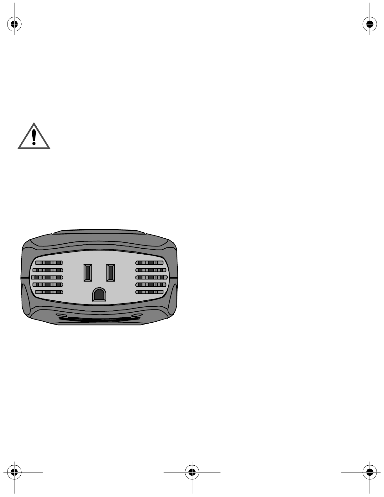
Figure 1 shows the AC panel of the 200 W unit.
OUTPUT: 115 VAC 60 HZ
160 W/1.4A Continuous
Figure 1
AC Panel of 200 W unit
An AC receptacle is loca ted on one end of the 200 W unit. You can plug
in 120 V appli ances wit h a combined total continuous power
consum ption of 160 W or less when the inverter is turned on.
6
XP_D igital_200-400-800.book Page 7 Wednesday, October 26, 2005 2: 51 PM
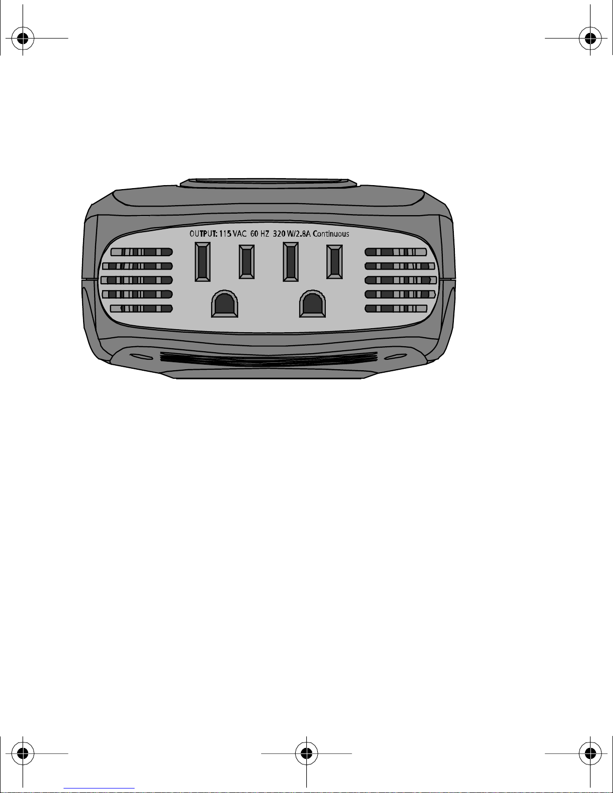
Figure 2 shows the AC panel of the 400 W unit, which is very s imila r to
the 800 W unit.
Figure 2
AC Panel of 400 W unit
Two AC receptacle s are located on one end of the 400 W unit and the
800 W unit. You can plug in 120 V appliance s wit h a combined total
cont inuous power consumption of 320 W (400 W unit) or 640 W
(800 W unit) or le ss when the inverter is turned on.
7
XP_D igital_200-400-800.book Page 8 Wednesday, October 26, 2005 2: 51 PM
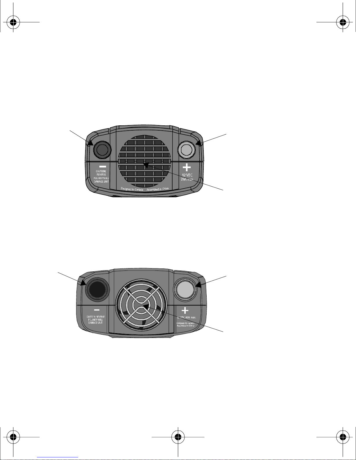
DC (Back) Panel
Figure 3 shows the DC pane l of the 200 W unit. Use Table 1 to i dentify
the function of items.
2B
Figure 3
DC Panel of 200 W unit
2A
1
Figure 4 shows the DC panel of the 800 W unit, which is very s imila r to
the 400 W unit. Use Table 1 to ident ify the function of items.
2B
2A
Figure 4
DC Panel of 800 W unit
8
1

XP_D igital_200-400-800.book Page 9 Wednesday, October 26, 2005 2: 51 PM
Table 1
DC Panel Functions
Item Function
1
Fan and Ventilation Openings
The cooling fan on the units are desi gned to operate only when
output power is gre ater than approximately 80 W. When the inverter
is tu rned on, the fan may oper ate momentarily. The ventilation
openings should not be cove red at any time w hile the inver ter is
operating.
2
A) Positive and B) Negative Cabling Terminals
Con nect th e ri ng te rmi nal s on th e power cables to th ese ter mina ls . To
ensure correct polarity, red must be connected to red and black must
be connected to black.
9

XP_D igital_200-400-800.book Page 10 Wednesday, Octo be r 26, 2005 2:5 1 PM
Digital Display (Top) Panel
Figure 5 shows the Digital Display panel. Use Table 2 to identify the
funct ion of items.
3
2
Figure 5
10
1
Digital Disp lay Panel

XP_D igital_200-400-800.book Page 11 Wednesday, Octo be r 26, 2005 2:5 1 PM
Table 2
Digital Display Panel Functions
Item Function
1 Swi tch to turn the unit on and off.
Press to toggle the display function to show input voltage, output
power and output vol tage.
2 Normal Operation
Digit al display sh ow s input volta ge, output power and output
voltage.
Erro r Mode
Digital display shows erro r codes and alarm sounds when unit has
shut down d ue t o under - vo ltage , o ver -vo lt age, o ver-load , over hea ting
or high - s u rge.
3 LEDs indi cate the status of the digital display.
Audible Alarm
An audib le alarm warn s you if an und er -vol t age shut down is abo ut to
occur.
11

XP_D igital_200-400-800.book Page 12 Wednesday, Octo be r 26, 2005 2:5 1 PM
Types of Connections
Cable Clamps/Battery
Product Lighter Plug Conne cti on
200 W unit Available – You must connect
Connections
Not Available
a separate lighter plug cable
(incl uded).
400 W unit Available – You must connect
a separate lighter plug cable
(incl uded).
Available – You must conn ect
a separate battery cl amp cable
(incl uded).
800 W unit Not Availab le Available – You must conn ect
a separate battery cl amp cable
(incl uded).
12

XP_D igital_200-400-800.book Page 13 Wednesday, Octo be r 26, 2005 2:5 1 PM
Accessories
Figure 6 shows the lighter plug cable that is included with the 200 W
unit and 400 W unit.
Figure 6
Lighter Plug Cable
Figure 7 shows the cable supplied with the 400 W unit and 800 W unit
for dire ct connection to a 12 V battery.
Figure 7
Cable for Direct Connection to a 12 V B at te ry
13

XP_D igital_200-400-800.book Page 14 Wednesday, Octo be r 26, 2005 2:5 1 PM
4 Conne cting the Digital Inverter
CAUTION
The Digital Inverter must only be connected to a battery that has a
nominal output of 12 V. It will not operate if connecte d to a 6 V batte ry
and may be damaged if connect ed to a bat tery with 16 V or m ore.
It is recommended that you hard wire the 800 W unit directly to the
12 V batter y.
Choosing a Location
For best performance, place the inverte r on a flat s urface in a location
tha t is :
Dry Do not expose the inver ter to water, rain, snow or spray.
Cool Operate the inverter in ambient temperatures between 0°C
and 40 °C (32 ° F and 100 °F ). Keep it away fr om heating
vents and direct sunlight.
Well-ventilated For proper cooling, allow at least 2 inches (5 cm) of
clearance around the inverter .
Clean and free of
dust and dirt
Safe Do not ins tall the in verter in a compartm ent with batteries
Choose a location that is free of an y debris that could get
into the inverter.
or fla m ma ble liquids, such as gasoline, or explosive vapors .
14

XP_D igital_200-400-800.book Page 15 Wednesday, Octo be r 26, 2005 2:5 1 PM
Connecting for Loads Under 150 W
Follow these steps to connect the 200 W unit or 400 W unit:
1. P lace the inverter on a flat surface such as the floor of your vehicle.
2. Make sure tha t the unit is off by verifying the digital display is off.
3. Take the power cord equipped with the lighter plug (Figure 6) and
place the ring terminals over the two cabling terminals on the back
of the inv erter. (The cabling termina ls are shown in Figure 3 and
Figure 4.)
CAUTION: Reverse polarity
Power connections of the 12 V DC battery to the Digi tal Invert er must
be positive to positive and negative to negative.
A reverse polarity connect ion (positive to negat ive) will blow a fuse in
the i nverter and may permanently damage the unit. Damage caused by a
reverse polarity connection is not covered by your warranty.
CA U TION
Make sure you connect red to re d and black to black, and make sure you
scr ew th e n ut s on tig h tly.
4. F asten the posit ive (red ) clam p to the posit ive batte ry post , and th en
fasten the negative (black) clamp to the nega tive ba ttery post.
15

XP_D igital_200-400-800.book Page 16 Wednesday, Octo be r 26, 2005 2:5 1 PM
5. Tighte n the nut on each DC te rminal until it is snug. Do not
over-tighten.
6. P lace the inverter’s lighter pl ug in the vehicle’s light er s ocket or a
12 V outlet.
7. Turn on the unit by holding the switc h located on top of the unit
until 888 is shown on the displa y.
The digit al displ ay will s how the ba ttery vol ta ge, ind icati ng th at the
Digital Inverter is opera ting normally and AC powe r is available at
the outlet.
8. Plug in the AC product you want to operate.
When not in use always turn the inverter off by holding the switch until
the di gital display turns off.
Connecting for Loads Over 150 W
You must connect the 400 W unit or 800 W unit directly to a 12 V
batte ry if you are going to operate loads greater than 150 W
cont inuously. When the inverter is connected this way, you can operate
load s of an y size up to 320 W continuous ly with a 400 W unit and
640 W continuously with a 800 W unit.
16

XP_D igital_200-400-800.book Page 17 Wednesday, Octo be r 26, 2005 2:5 1 PM
W ARN ING : Shock hazard
Batteries cont ain corrosive materials and pres ent an electrical shock
hazard. To prevent irritation and burns, wear protect ive eyewear and
clot hing when you in stall the in verter or work with the batterie s. Take
special care t o ensure that m etal tools and personal metal objects like
rings and bracelets do not contact the battery term inals.
Follow these steps to make a dir ec t battery connection:
1. Pla ce th e in v erter on a flat s u rfa ce.
2. Make sure tha t the unit is off by verifying the digital display is off.
CAUTION: Reverse polarity
Power connections of the 12 V DC battery to the Digi tal Invert er must
be positive to positive and negative to negative.
A reverse polarity connect ion (positive to negat ive) will blow a fuse in
the inverter and may permanently damage the unit. D amage caused by a
reverse polarity connection is not covered by your warranty.
3. Take the cable s equi pped with ba tt ery cla mps on one e nd (Figu re 7)
and place the ring terminals over the two cabling terminals on the
back of the inverter. (The cabling terminals are shown in Figure 3
and Figure 4.)
17

XP_D igital_200-400-800.book Page 18 Wednesday, Octo be r 26, 2005 2:5 1 PM
CA U TION
Make sure you connect red to red and black to black, and make sure you
scr ew th e n ut s on tig h tly.
4. F asten the posit ive (red ) clam p to the posit ive batte ry post , and th en
fasten the negative (black) clamp to the nega tive ba ttery post.
5. Turn on the unit by holding the switc h located on top of the unit
until 888 is shown on the displa y.
The digit al displ ay will s how the ba ttery vol ta ge, ind icati ng th at the
Digital Inverter is opera ting normally and AC powe r is available at
the outlet.
6. P lug in the AC appliance you want to operate.
When no t in use, always turn the inverter off by holding the switch until
the di gital display turns off.
18

XP_D igital_200-400-800.book Page 19 Wednesday, Octo be r 26, 2005 2:5 1 PM
5 Operating the Digital Inverter
This s ection explains how to operate the Digital Inve rter most
efficiently.
Operating Conditions and Guidelines
This s ection describe s normal oper ation as well as conditi ons that
trigger an alar m or automatically shut down the Digital Inverter.
Normal Operation When you connect the inverter to the vehic le’s
lighte r socket or directly to a 12 V battery and turn on the unit, the
digital display will show input voltage, the input voltage
LED
illuminates and AC power is available at the outlets. You can now plug
in your AC products and turn them on one at a time.
Low Battery Alarm and Shutdown As the batte ry discharges , its
voltage decrea ses. When the Digita l I nverter senses that the vo ltage at
its DC input has dropped to 11.0 V, it sounds an alarm, giving you time
to shut down sensi tive loads such as computers. If you ignore the alarm,
and the DC input voltage drops below 10.5 V, the inverte r shuts down
all loads to s ave the battery from further discha rge. The under-voltage
error code ‘E 01’ will show on the digital display.
19

XP_D igital_200-400-800.book Page 20 Wednesday, Octo be r 26, 2005 2:5 1 PM
High-input Vol tage Shutdown If a defective battery charging system
cause s the batte ry voltage to rise to dang erously high levels, the Digital
Invert er shuts down automatically. The over-vol tage error cod e ‘E02 ’
will show on the digi tal display.
Overload Shutdown If you connect an AC loa d that is rate d too high
(see Tabl e 3 ) or a lo ad tha t dr a w s ex ce ss i v e s u rge po w e r, the Digi t al
Inverter s huts down. The overload error code ‘E03’ will show on the
digital display.
Overheating Shutdown The Digital Inverter shut s down
aut om at ical l y if it e x ce ed s its saf e o pe r at in g temp er a tu r e. T he
overhe ating error code ‘E04’ will show on the digital display.
Shut ting the inv erter off
• If you are going to dis connect the battery, turn the inverter off first.
• Turn the inverter off by holding the switch until the display turns
off.
20

XP_D igital_200-400-800.book Page 21 Wednesday, Octo be r 26, 2005 2:5 1 PM
Operating normal loads
The Digital Inverter is capabl e of continuously poweri ng most 120 V
AC product s with the following power rating maximums:
Table 3
Product
200 W unit 200 W 160 W 400 W
400 W unit 400 W 320 W 700 W
800 W unit 750 W 640 W 1200 W
Po wer and Surge Ratings
5 min Max.
Power Rating
Continuous
Power Rating
Sur ge Rating
Max.
The inverter’s AC (“modi fied sine wave”) output waveform is designed
to funct ion simil arly to the sine wave shape of utility power. Most AC
produc ts c orrect ly r ated for the power ra tin g maxi mums lis ted i n Table 3
or less will operate norm ally with the D igital Inverter.
21

XP_D igital_200-400-800.book Page 22 Wednesday, Octo be r 26, 2005 2:5 1 PM
Operating loads with high surge requirements
The power, or wattage rating, of AC loads is the average amount of
power t hey use. Some appli ances c onsume more powe r than t heir po wer
rating when they are first turned on. TV s, monito r s, and el ectric mo to r s
are some products that have high sur ge requirements at star t up. The
Digital Invert er ca n s upply momentary surge power that is higher than
its maxim um power rating. Some products rated less than power r ating
maximum for your inverter may exc eed its surge capability and trigger
an over load shutdown. If this problem occurs when attempting to
opera te several AC products at the same time, tr y firs t turning on the
inve rter with all AC products turned off, then one by one tu rn ea ch on,
starting with the high-surge product first.
22

XP_D igital_200-400-800.book Page 23 Wednesday, Octo be r 26, 2005 2:5 1 PM
Table 4
Pro duct
Wattage of Common AC Products
a
Watts
b
200 W unit 400 W unit 800 W unit
Cell ph one/camcorder
10 Yes Yes Yes
charger
Video game console 20 Yes Yes Yes
Portable work light 25 Yes Yes Yes
Stereo system 50 Yes Yes Yes
Laptop computer 75 Yes Yes Yes
13" TV 100 Yes Yes Yes
27" TV 200 Yes Yes
20" TV/VCR combo 300 Yes Yes
Small appliances 400+ Yes
Power tools 400+ Yes
a.Power requirem ents for prod uct examples are estimates onl y. To calcu late the wattage of a product, use
the following equation: amperage x 115.
b.If you want to pow er two or more pro ducts simultaneously, ad d the power requirements of both prod-
ucts to determine the total wattage.
23

XP_D igital_200-400-800.book Page 24 Wednesday, Octo be r 26, 2005 2:5 1 PM
6 Maintaining Battery Condit ion
The battery oper ating time of the Digital Inverter de pends on the charge
level of the battery, ba ttery capacity, and t he amount of power drawn by
the AC loads you are operating. With a typical ve hicle battery, you can
expect the following:
Table 5
Inverter L oa d Sample Appliance Operating Time
200 W un it 50 W CD player 6–8 hours
400 W unit 100 W small TV 3–4 hours
800 W un it 200 W TV/VCR 1–2 hours
Battery Operating Times
24

XP_D igital_200-400-800.book Page 25 Wednesday, Octo be r 26, 2005 2:5 1 PM
Here are some guidelines that will hel p to preserve your battery:
• Vehicle batteries are not designed for repeated deep-discharge
cycles , and cons tantl y rechar gi ng a vehic le’s bat tery wil l shorte n its
life. Th erefore, when you are using a vehicle batte ry as a power
sour ce, start the vehicle every hour or two to recharge the battery.
• The Digital Inverter will operate whil e the engine is running, but
the vol tage drop that occurs when the engine starts may trigger a
low-voltage shutdown.
• Vehicle batteries are designed to provide brief periods of very high
current needed for engine starting. They are not intended for
constant deep discharge. Regul arly operating the Digita l Inverter
from a vehicle battery until the low-voltage alarm s ounds will
shor ten the life of the batte r y. Consider connecting the Digital
Invert er to a separate dee p discharge-type batter y if you will be
freque ntly running electrical products for extended perio ds of ti me .
• If you are not going to use the Digital Inverter for a few days, turn
off the unit. The in verter d raws 0.4 A or less whe n th e unit is on and
no load is connecte d , but it will eventually discharge the batt ery.
25

XP_D igital_200-400-800.book Page 26 Wednesday, Octo be r 26, 2005 2:5 1 PM
7 Troubleshooting
This s ection will help you identi fy the source of m ost problems that can
occur with the Digital Inverter.
If you have a problem with the inverter, please review this section
before contacting your dealer. If you are unable to solve a probl em and
need to contact service, please prepare for the call by writing down the
following details:
• Inverter’s serial number
• How long the inverter has been in use
• Wh er e it is in sta lled
• Appliances operati ng when the problem occurred
• A brie f description of the prob lem
26

XP_D igital_200-400-800.book Page 27 Wednesday, Octo be r 26, 2005 2:5 1 PM
Common Problems
W ARN ING : Electrical shock and burn hazard
Do not disassemble the Di gital Inver ter. It does not contain any userserv ic eab le pa rt s. A tte m ptin g t o s er vic e the i nve rter yo urs el f cou ld re sult
in an el ectrical shock or bur n.
Buzz in audio systems
Some in expensive stereo s ystems have inadequate interna l power
supply f ilteri ng and buzz slight ly when power ed by the Digital Inverter .
The bes t so lution is to use an audio system with a hig h-quality filter.
Television interference
The Digital Inverter is shielded to minimize interference with T V
signal s. If TV signa ls are weak, you may see interference in the form of
lines scrolling across the screen. Try one of these suggestions to
minimize or elim inate the problem:
• Adjust the orientation of the Digital Inverte r, television, antenna,
and cables.
• Maximize TV signal strength by using a better antenna, and use
shielded antenna cab le wher e p o ssible.
• Try a different TV. Different models vary cons iderably in their
susceptibility to interfer ence.
27

XP_D igital_200-400-800.book Page 28 Wednesday, Octo be r 26, 2005 2:5 1 PM
Troubleshooting Reference
This section describes problem s, their symptoms, possible ca uses, and
solutions.
Problem: The AC load will not operate. Digital d isplay is off.
Pos sible Cause Solution
Batte ry is defective. Check battery and replace if required.
The i nvert er ha s b een co nne ct ed
with reverse DC input polarity.
Loose cable connections. Check cables and connections.
Check connection to battery.
The inverter has likely been damaged and
needs to be repaired.
Have the unit repaired (not covered un der
warranty).
Tighten as required.
Problem: Th e inverter will r u n some small loads, but not larger ones.
Pos sible Cause Solution
Voltage drop across DC cables. Shorten ca bles or use heavi er cables.
28

XP_D igital_200-400-800.book Page 29 Wednesday, Octo be r 26, 2005 2:5 1 PM
Prob lem: Measur ed inverter outp ut is too low.
Pos sible Cause Solution
A standard “average-reading”
AC vo lt m e te r ha s b ee n use d to
measure output vol tage,
resulting in an ap parent reading
For accurate measurement, the Digital
Inverter modifi ed sine wave output require s
a “true RMS” voltmeter for accurate
measurements.
5–15 V too low.
The batt ery voltage is too low. Recharge the battery.
Problem: Battery run time is less than expected.
Pos sible Cause Solution
The AC product power
consumption is higher tha n
rated.
The battery is old or defective. Replace the battery.
Use a larger batt ery to make up for the
increased power requirement .
The bat tery i s not be in g char ge d
properly.
Some chargers are not able to fully recharge
a batt ery. Mak e sure th at you use a power ful
charger.
Power dissipati on in DC cables. Use shorter/hea vier DC cables.
29

XP_D igital_200-400-800.book Page 30 Wednesday, Octo be r 26, 2005 2:5 1 PM
Problem: T he AC load w i ll not operate, error code shows on di gi tal
display and alarm is sounding.
Error Possible Cause Solution
E01 Low voltage shutdown because
battery is discharged.
E02 O ver - volt age shutdo wn be cau se
of hi gh input voltage.
E03 The AC product(s) connected
are rated at more than the
inverter’s continuous power
rating; overload shutdown has
occurred.
E04 T he in ver ter ha s overhe at ed due
to poor ventilation.
Overheating shutdown has
occurred.
Recharge battery.
Shorten cables or use heavier
cables.
Ve r ify the ch a rgi ng sy stem is
properly regulated and the battery
is 12 V nominal .
Use a product with a po w er rating
within the inverte r’s cont in uo u s
power rat ing (see Table 3).
Turn inverter off and allow to cool
for 15 minu tes. Clear bl ocked fan
or remove objects covering u nit.
Move the inve rter to a co o ler
place. Reduce load if continuous
operation is required.
E05 The AC product s connected
have a sur ge po wer tha t ex ceeds
the Digital Inverter’s surge
capability or the AC prod ucts
connected are short-circuited
and shutdown has occurred.
30
The products exceed the inverter’s
surge capability. Use a product
with a starting surge power within
the Digi tal Inverte r’s capability.

XP_D igital_200-400-800.book Page 31 Wednesday, Octo be r 26, 2005 2:5 1 PM
8 Specifications
Specifications are subject to change without notice.
200 W unit 400 W unit 800 W unit
AC output volt a ge (nominal) 120 V AC
DC input voltage range 10.5 –15.5 V DC
Maximum continuous AC
outpu t power
5 minute s A C output power 200 W 400 W 750 W
Maximum AC o utput surge
power
AC output fre quency 60 ± 1 Hz
AC output wavef or m Modified Sine Wave
No load curr e nt draw
(at 12 V input)
160 W 320 W 640 W
400 W 700 W 1200 W
0.3 A 0.3 A 0.4 A
a
Efficiency (maximum) 90%
Ambient operating
temperat ur e range
Storage temperature -20–60 °C -4 –140 °F
0–40 ° C 32–104 °F
31

6
-- -
5
8
-- -
1
2
-- -
1
2
-- -
3
8
-- -
XP_D igital_200-400-800.book Page 32 Wednesday, Octo be r 26, 2005 2:5 1 PM
a
Low volt age alarm
Low voltage shutdo wn
High vol tage shutdown
Dimensions
(L × W × H)
200 W unit 400 W unit 800 W unit
11.0 V
10.5 V
15.5 V
102 × 84 × 51 mm
5
---
4 × 3 × 2"
1
11.0 V
10.5 V
15.5 V
137 × 102 × 51 mm
5 × 4 × 2"
11.0 V
10.5 V
15.5 V
141 × 114 × 61 mm
7 × 4 × 2"
W eight 10 oz (0.28 kg) 1 lb (0. 44 kg) 1 lb 13 oz (0.82 kg)
a.Provides maximum 800 watts of AC output power for up to 1 minute.
32

XP_D igital_200-400-800.book Page 33 Wednesday, Octo be r 26, 2005 2:5 1 PM
9 Warranty and Return
Warranty
What does this warranty cover? Thi s Limit ed Warranty is provided by
Xantrex Technology Inc. ("Xa ntrex") and covers defects in workmanship and
materials in your D igital In verter 200 W, 400 W, 800 W. This warranty period
lasts for six (6) months from the dat e of purchase at the point of sale to you, the
original end user customer. You require proof of purchase to make warranty
claims.
What will Xantrex do? Xantrex will, at its option, repair or replace the
defe ct ive pr odu ct fr ee o f c har ge, pr ovided th at you n ot if y Xan trex o f t he pro duc t
defe ct withi n t he Warr anty Pe ri od, a nd pr ov ided t hat Xan trex t hr oug h insp ect ion
establishes the existence of such a defect and that it is covered by this Limited
Warranty.
Xantrex will, at its option, use new and/or reconditioned parts in performing
warr ant y repai r and bu ildi ng r eplac ement pr oducts . Xa ntrex res erves the ri ght to
use p ar ts or pro duc ts of o ri gi nal or imp rov ed d esign in the repai r or rep laceme nt.
If Xa ntr ex rep ai rs or repl ac es a produc t, its warr an ty cont in ues for t he r emai ni ng
portion of the or iginal Warranty Period or 90 da ys from the date of the r eturn
shipment to the customer, whichever is greater. All replaced products and all
parts removed from repaired products become the property of Xantrex.
Xantrex covers both parts and labor necessary to repair the product, and return
shipment to the cu stomer via a Xa ntrex-selected non-expedited sur face freight
within the contiguous Un ited States and Canad a. Alaska and Hawaii are
excluded. Contact Xantrex Customer Service for details on freight policy for
ret urn shi pm ents outsid e of the contiguous United S tates and Canad a.
33

XP_D igital_200-400-800.book Page 34 Wednesday, Octo be r 26, 2005 2:5 1 PM
How do yo u get service?
If your product requires troubleshooting or war ranty service, contact your
dealer.
If you are unable to conta ct your dealer, or the dealer is unab le to pr ovide
service, contact Xantrex directly at:
Telep hone: 1 360-925-5097
Fax: 1 360- 925-5143
Web: www.xantrex.com/support
Direct returns may be perform ed according to the Xantrex Return Material
Authorization Policy described in your prod uct manual. For some products,
Xantrex maintains a network of regional Authorized Service Centers. Call
Xantrex or check ou r w ebsite to see if your product can be repa ired at one of
these facilities.
Wha t pro o f of pu rch as e is requ ired ? In any warranty cla im, date d proof of
purchase must accompany the product and the product must not ha ve been
disassembled or modi fied without prior w ritten authorization by Xantrex.
Proof of purchase may be in any one of the following forms:
• The dated purchase receipt from the original purchase of the product at
point of sale to the end user, or
• The dated dealer invoice or purchase receipt showing original equipment
manufacturer (OEM) status, or
• The dated invoice or purch ase receipt showing the product exchanged
under warranty
34

XP_D igital_200-400-800.book Page 35 Wednesday, Octo be r 26, 2005 2:5 1 PM
What does this warranty not cover? This Limited Warranty does not cover
normal wear and tear of the product or costs related to the removal, installation,
or troubleshooting of the custome r's electrical systems. This w arranty does not
apply to and Xantrex will no t be responsible for any defect in or dama ge to:
a) the product if it has been misused, neglected, imp roperly inst alled, phys i-
cally damaged or al tered, eit her internally or externally, or damaged from
improper use or use in an unsuitable en vironment;
b) the produ ct if it has been subjected to fire, w ater, generalized corrosi on,
biol ogical infestatio ns, or input vol tage that cr eates operating condit ions
beyond the maximum or minimum limits l isted in the Xantrex product
specifications including high input vol tage from generators and lightning
strikes;
c) the product if repairs have been done to it other than by Xantrex or its
authorized service centers (her eafter "ASCs");
d) the produ ct if it is used as a component part of a product expr essly war-
ranted by another manufacturer;
e) the pro d uc t if its or ig in a l id en tifi ca tio n (tr a de -mar k, seria l nu mb er) mark -
ings have been defaced, altered, or removed.
Disclaimer
Product
THIS LIMITED WARRANTY IS THE SOLE AND EXCLUSIVE WARRANTY
PROVIDED BY XANTREX IN CONNECTION WITH YOUR XANTREX PRODUCT
AND IS, WHERE PERMITTED BY LAW, IN LIEU OF ALL OTHER WARRANTIES,
CONDITIONS, GUARANTEES, REPRESENTATIONS, OBLIGATIONS AND
LIABILITIES, EXPRESS OR IMPLIED, STATUTORY OR OTHERWISE IN
35

XP_D igital_200-400-800.book Page 36 Wednesday, Octo be r 26, 2005 2:5 1 PM
CONNECTION WITH THE PRODUCT, HOWEVER ARISING (WHETHER BY
CONTRACT, TORT, NEGLIGENCE, PRINCIPLES OF MANUFACTURER'S
LIABILITY, OPERATION OF LAW, CONDUCT, STATEMENT OR OTHERWISE),
INCLUDING WITHOUT RESTRICTION ANY IMPLIED WARRANTY OR
CONDITION OF QUALITY, MERCHANTABIL ITY OR FITNESS FOR A
PARTICULAR PURPOSE. ANY IMPLIED WARRANTY OF MERCHANTABILITY
OR FITNESS FOR A PARTICULAR PURPOSE TO THE EXTENT REQUIRED
UNDER APPLICABLE LAW TO APPLY TO THE PRODUCT SHALL BE LIMITED
IN DURATION TO THE PERIOD STIPULATED UNDER THIS LIMITED
WARRANTY.
IN NO EVENT WILL XANTREX BE LIABLE FOR ANY SPECIAL, INDIRECT,
INCIDENTAL OR CONSEQUENTIAL DAMAGES, LOSSES, COSTS OR EXPENSES
HOWEVER ARISING WHETHER IN CONTRACT OR TOR T INCLUDING
WITHOUT RESTRICTION ANY ECONOMIC LOSSES OF ANY KIND, ANY LOSS
OR DAMAGE TO PROPERTY, ANY PERSONAL INJURY, ANY DAMAGE OR
INJURY ARISING FROM OR AS A RESULT OF MISUSE OR ABUSE, OR THE
INCORRECT INSTALLATION, INTEGRATION OR OPERATION OF THE
PRODUCT.
Exclusions
If th is prod uct is a consumer pro duct , fede ra l law does no t al low an ex clusi on of
implied warrant ies. To the extent you are entitled to impl ied warranties under
federal law, to the extent permitted by applicable law they are limited to the
duration of this Limited Warranty. Some states and provinces do not al low
limitations or exclusions on implied warranties or on the du ration of an impl ied
warranty or on the limitation or exclusion of incidental or consequential
36

XP_D igital_200-400-800.book Page 37 Wednesday, Octo be r 26, 2005 2:5 1 PM
damages, so the abo v e limitation(s) or exclu sion(s) may not apply to you. This
Limited Warrant y gives you specific legal rights. You may have other rights
which may vary from state to state or province to provin ce.
Wa rning: Limitations On Use
Please refer to your product manual for limi tations on us es of the product.
SPECIF ICA L LY, PLEASE N OTE TH AT TH E DIGITAL INVERTER 200 W, 400 W,
800 W
SYSTEMS OR OTHER MEDICAL EQUIPMENT OR DEVICES. WITHOUT
LIMITING THE GENERALITY OF THE FOREGOING, XANTREX MAKES NO
REPRESENTATIONS OR WARRANTIES REGARDING THE USE OF THE
XANTREX
LIFE SUPPORT SYSTEMS OR OTHER MEDICAL EQUIPMENT OR DEVICES.
SHOULD NOT BE USED IN CONNECTION WITH LIFE SUPPORT
DIGITAL INVERTER 200 W, 400 W, 800 W IN CONNECTION WITH
Return Material Authoriza tion Policy
Before return ing a prod uct directly to Xantrex you must obtain a Return
Material Author ization (RMA) number and the correct fac tory "Ship To"
address. Products must also be shipped prepaid. Product shipments will be
refused and ret u rned at your expense if they are unauthorized, returned without
an RMA number clearl y marked on the outside of the shipping box, if the y are
shipped collect, or if they are shipped to the wrong location.
37

XP_D igital_200-400-800.book Page 38 Wednesday, Octo be r 26, 2005 2:5 1 PM
When you contact Xantrex to obtain service, please have your instruction
manual ready for reference and be prepared to supply:
• The serial number of your product
• Information about the installation and use of the unit
• Information about the failure and/or reason for the return
• A copy of your dated pro of of purchase
38

XP_D igital_200-400-800.book Page 39 Wednesday, Octo be r 26, 2005 2:5 1 PM
Return Procedure
1. Package the unit safely , prefera bly usi ng the origina l box and pa cking
materials. Please ensure that your product is shipped fully ins ured in the
ori ginal packaging or equiva lent. This warranty will not apply where the
product is damage d due to impr oper packaging.
2. Include the fol lowing:
• The RMA numb er supplied by Xantrex Technolog y Inc. clearl y
marked on the outsi de of the box.
• A return address where the uni t can be shipped. Post office boxes are
not acceptab le.
• A contact telephone number where you can be reached during work
hours.
• A brief descr iption of the problem.
3. Ship the unit prepaid to the address provided by your Xantrex customer
service representative.
If you are returning a product from outside of the USA or Canada In
addition to the above, you MUST include return freight funds and are fully
responsible for all documents, duti es, tariffs, and deposits.
If you are returning a product to a Xantrex Authorized Service Center
(ASC) A Xantrex return m aterial au thorizati on (RMA) number is not required.
However, you must contact t he ASC prior to ret urning the product or presenting
the unit to verify any return proce dures that may apply to that particular fac ility.
39

XP_D igital_200-400-800.book Page 40 Wednesday, Octo be r 26, 2005 2:5 1 PM
Out of Warranty Service
If t he w arranty per iod for your Digi tal Inverte r 200 W, 400 W, 800 W has
expired, if the unit was dama ged by misuse or incorr ect installation, if other
condi tion s of t he war ranty have not bee n met, or if no date d pro of of purc has e is
available, your unit may be serviced or replaced for a flat fee.
To return your Digital Inver ter 200 W, 400 W, 800 W for out of warranty
service, contact Xantrex Customer Service for a Return Material Authorization
(RM A) num ber and follow the other steps outlined in “Return Procedur e” on
page 39.
Payment options such as credit card or mo ney order will be explained by the
Customer Service Representati ve. In cases where the minim um flat fee does not
appl y , a s wi th in compl et e uni ts or uni t s with exc ess ive d amage , an a ddit ion al fe e
will be charged. If applicable, you w ill be contacted by Customer Ser vice once
your unit has been received.
10 Oth er Xa n trex Pro du ct s
To see the range of inverters and chargers offered by Xantrex, visit our
web site at www.x a ntrex .com.
40
 Loading...