

XKW 8-350
XKW 10-300
XKW 12-150
XKW 20-150
XKW 40-75
XKW 55-55
XKW 60-50
XKW 80-37
XKW 150-20
XKW 300-10
Operating Manual
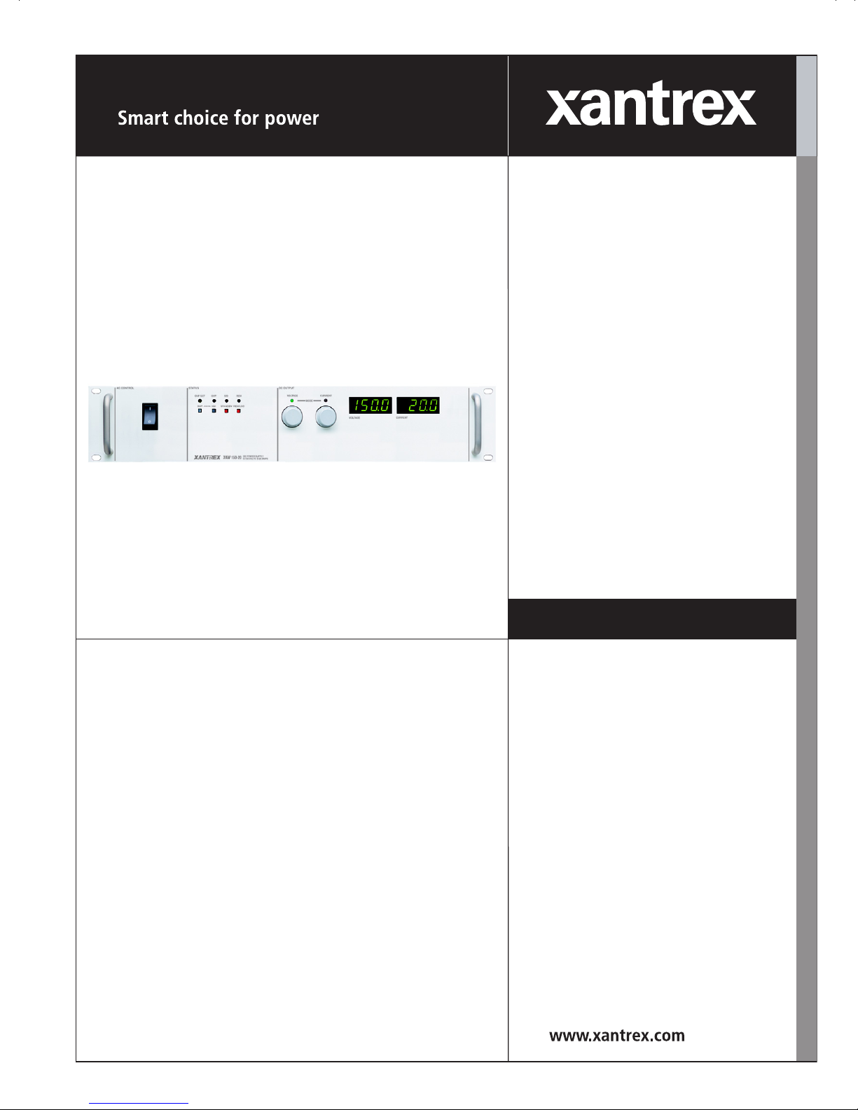
XKW 3000 Watt Series
Programmable DC
Power Supply


Operating Manual for
XKW 3000 Watt Series
Programmable DC
Power Supply

Limited
Warranty
What does this warranty cover and how long does it last?
This Limited Warranty is provided by Xantrex Technology, Inc. (“Xantrex”) and
covers defects in workmanship and materials in your XKW 2500 Watt Series DC
Power Supply. This warranty lasts for a Warranty Period of 5 years from the date of
purchase at point of sale to you, the original end user customer.
What will Xantrex do?
Xantrex will, at its option, repair or replace the defective product free of charge,
provided that you notify Xantrex of the product defect within the Warranty Period,
and provided that Xantrex through inspection establishes the existence of such a
defect and that it is covered by this Limited Warranty.
Xantrex will, at its option, use new and/or reconditioned parts in performing
warranty repair and building replacement products. Xantrex reserves the right to use
parts or products of original or improved design in the repair or replacement. If
Xantrex repairs or replaces a product, its warranty continues for the remaining
portion of the original Warranty Period or 90 days from the date of the return
shipment to the customer, whichever is greater. All replaced products and all parts
removed from repaired products become the property of Xantrex.
Xantrex covers both parts and labor necessary to repair the product, and return
shipment to the customer via a Xantrex-selected non-expedited surface freight
within the contiguous United States and Canada. Alaska and Hawaii are excluded.
Contact Xantrex Customer Service for details on freight policy for return shipments
outside of the contiguous United States and Canada.
How do you get service?
If your product requires troubleshooting or warranty service, contact your merchant.
If you are unable to contact your merchant, or the merchant is unable to provide
service, contact Xantrex directly at:
Telephone: 1 800 670 0707 (toll free North America)
1 360 925 5097 (direct)
Fax: 1 800 994 7828 (toll free North America)
1 360 925 5143 (direct)
Email: customerservice@xantrex.com
Web: www.xantrex.com
ii Operating Manual for XKW 3kW Series Power Supply

Direct returns may be performed according to the Xantrex Return Material
Authorization Policy described in your product manual. For some products, Xantrex
maintains a network of regional Authorized Service Centers. Call Xantrex or check
our website to see if your product can be repaired at one of these facilities.
In any warranty claim, dated proof of purchase must accompany the product and the
product must not have been disassembled or modified without prior written
authorization by Xantrex.
Proof of purchase may be in any one of the following forms:
• The dated purchase receipt from the original purchase of the product at point of
sale to the end user, or
• The dated dealer invoice or purchase receipt showing original equipment
manufacturer (OEM) status, or
• The dated invoice or purchase receipt showing the product exchanged under
warranty
What does this warranty not cover?
This Limited Warranty does not cover normal wear and tear of the product or costs
related to the removal, installation, or troubleshooting of the customer’s electrical
systems. This warranty does not apply to and Xantrex will not be responsible for any
defect in or damage to:
a. the product if it has been misused, neglected, improperly installed, physically
damaged or altered, either internally or externally, or damaged from improper
use or use in an unsuitable environment;
b. the product if it has been subjected to fire, water, generalized corrosion,
biological infestations, and high input voltage from lightning strikes;
c. the product if repairs have been done to it other than by Xantrex or its authorized
service centers (hereafter “ASCs”);
d. the product if it is used as a component part of a product expressly warranted by
another manufacturer;
e. the product if its original identification (trade-mark, serial number) markings
have been defaced, altered, or removed.
Revision A iii

Disclaimer Product
THIS LIMITED WARRANTY IS THE SOLE AND EXCLUSIVE WARRANTY PROVIDED
BY XANTREX IN CONNECTION WITH YOUR XANTREX PRODUCT AND IS, WHERE
PERMITTED BY LAW, IN LIEU OF ALL OTHER WARRANTIES, CONDITIONS,
GUARANTEES, REPRESENTATIONS, OBLIGATIONS AND LIABILITIES, EXPRESS
OR IMPLIED, STATUTORY OR OTHERWISE IN CONNECTION WITH THE PRODUCT,
HOWEVER ARISING (WHETHER BY CONTRACT, TORT, NEGLIGENCE, PRINCIPLES
OF MANUFACTURER’S LIABILITY, OPERATION OF LAW, CONDUCT, STATEMENT
OR OTHERWISE), INCLUDING WITHOUT RESTRICTION ANY IMPLIED WARRANTY
OR CONDITION OF QUALITY, MERCHANTABILITY OR FITNESS FOR A
PARTICULAR PURPOSE. ANY IMPLIED WARRANTY OF MERCHANTABILITY OR
FITNESS FOR A PARTICULAR PURPOSE TO THE EXTENT REQUIRED UNDER
APPLICABLE LAW TO APPLY TO THE PRODUCT SHALL BE LIMITED IN DURATION
TO THE PERIOD STIPULATED UNDER THIS LIMITED WARRANTY.
IN NO EVENT WILL XANTREX BE LIABLE FOR ANY SPECIAL, DIRECT, INDIRECT,
INCIDENTAL OR CONSEQUENTIAL DAMAGES, LOSSES, COSTS OR EXPENSES
HOWEVER ARISING WHETHER IN CONTRACT OR TORT INCLUDING WITHOUT
RESTRICTION ANY ECONOMIC LOSSES OF ANY KIND, ANY LOSS OR DAMAGE TO
PROPERTY, ANY PERSONAL INJURY, ANY DAMAGE OR INJURY ARISING FROM OR
AS A RESULT OF MISUSE OR ABUSE, OR THE INCORRECT INSTALLATION,
INTEGRATION OR OPERATION OF THE PRODUCT.
Exclusions If this product is a consumer product, federal law does not allow an exclusion of
implied warranties. To the extent you are entitled to implied warranties under federal
law, to the extent permitted by applicable law they are limited to the duration of this
Limited Warranty. Some states and provinces do not allow limitations or exclusions
on implied warranties or on the duration of an implied warranty or on the limitation
or exclusion of incidental or consequential damages, so the above limitation(s) or
exclusion(s) may not apply to you. This Limited Warranty gives you specific legal
rights. You may have other rights which may vary from state to state or province to
province.
iv Operating Manual for XKW 3kW Series Power Supply

Information WITHOUT LIMITING THE GENERALITY OF THE FOREGOING, UNLESS
SPECIFICALLY AGREED TO BY IT IN WRITING, XANTREX
a. MAKES NO WARRANTY AS TO THE ACCURACY, SUFFICIENCY OR SUITABILITY
OF ANY TECHNICAL OR OTHER INFORMATION PROVIDED IN MANUALS OR
OTHER DOCUMENTATION PROVIDED BY IT IN CONNECTION WITH THE
PRODUCT; AND
b. ASSUMES NO RESPONSIBILITY OR LIABILITY FOR LOSSES, DAMAGES,
COSTS OR EXPENSES, WHETHER SPECIAL, DIRECT, INDIRECT,
CONSEQUENTIAL OR INCIDENTAL, WHICH MIGHT ARISE OUT OF THE USE OF
SUCH INFORMATION.
THE USE OF ANY SUCH INFORMATION WILL BE ENTIRELY AT THE USER’S RISK.
WARNING:
Limitations
on Use
Information
About Your
Power
Supply
Please refer to your product user manual for limitations on uses of the product.
Specifically, please note that this power supply is not intended for use in connection
with life support systems and Xantrex makes no warranty or representation in
connection with any use of the product for such purposes.
Xantrex Technology, Inc.
8999 Nelson Way
Burnaby, British Columbia
Canada V5A 4B5
Please record the following information when you first open your Power Supply
package:
Model Number ______________________________________________
Serial Number ______________________________________________
Purchased From ______________________________________________
Purchase Date ______________________________________________
Release Revision A (2003-12)
Copyright © 2003 Xantrex Technology Inc. All rights reserved.
Printed in Canada
Revision A v
Warnings
!
!
!
and
Cautions
Power
Supply
Safety
Warnings and cautions are defined and formatted in this manual as shown below.
WARNING
Describes a potential hazard which could result in injury or death, or, a procedure
which, if not performed correctly, could result in injury or death.
CAUTION
Describes a procedure which, if not performed correctly, could result in damage
to data, equipment, or systems.
WARNING—High Energy and High Voltage
Exercise caution when using and calibrating a power supply. High energy levels
can be stored at the output voltage terminals on a power supply in normal
operation. In addition, potentially lethal voltages exist in the power circuit and on
the output and sense connectors of a power supply with a rated output greater
than 40 V. Filter capacitors store potentially dangerous energy for some time after
power is removed.
CAUTION
Operate the power supply in an environment free of flammable gases or fumes. To
ensure that the power supply’s safety features are not compromised, use the
power supply as specified in this manual and do not substitute parts or make any
unauthorized modifications. Contact the service technician for service and repair
help. Repairs must be made by experienced service technicians only.
CAUTION
For Use as a Battery Charger
When you are using any of these power supplies for battery charging applications,
it is essential to provide an appropriately sized fuse or circuit breaker in series
between the power supply output and the battery.
Installation of a protector (fuse or DC circuit breaker) rated for about 115% of the
maximum current rating of the power supply and designed specifically to interrupt
the DC voltage of the battery, will provide adequate reverse polarity current
protection. Where several power supplies are in parallel, it is best to fuse each one,
rather than one large fuse for all.
vi Operating Manual for XKW 3kW Series Power Supply

About This Manual
This Operating Manual contains user information for the XKW Series of variable
DC output power supplies, available in several voltage models at 3000 Watts. It
provides information about features and specifications, installation procedures, and
basic functions testing, as well as operating procedures for using both front panel
control and remote analog programming functions.
Who Should Use This Manual
This manual is designed for the user who is familiar with basic electrical laws
especially as they apply to the operation of power supplies. This implies a
recognition of Constant Voltage and Constant Current operating modes and the
control of input and output power, as well as the observance of safe techniques while
making supply or pin connections and any changes in switch settings.
Main Sections
Section 1 Features and Specifications Describes the power supply and lists
its features and specifications.
Section 2 Installation Goes through basic setup procedures. Describes
inspection, cleaning, shipping, and storage procedures. Includes AC input
connection, basic functions testing, and load and sense lines connections.
Section 3 Operation Provides procedures for local (front panel) operation.
Includes procedures for using over voltage protection, shutdown function, multiple
supplies, and over temperature protection.
Section 4 Calibration Includes calibration for programming and readback
accuracy.
Manual Revisions
The current release of this manual is listed below. Updates may be issued as an
addendum.
Revision A (2003-12)
Revision A vii

About This Manual
Power Supply Safety Markings
Alternating Current Off (Supply)
Earth (Ground) Terminal Caution (Hot Surface)
Protective Conductor Terminal Caution (Check manual for
additional information.)
On (Supply)
viii Operating Manual for XKW 3kW Series Power Supply

Contents
About This Manual . . . . . . . . . . . . . . . . . . . . . . . . . . . . . . . . . . . . . . . . . . . . . . . . . . . vii
List of Figures . . . . . . . . . . . . . . . . . . . . . . . . . . . . . . . . . . . . . . . . . . . . . . . . . . . . . . .xiii
List of Tables . . . . . . . . . . . . . . . . . . . . . . . . . . . . . . . . . . . . . . . . . . . . . . . . . . . . . . . xv
Section 1.
Features and
Specifications
Section 2.
Installation
Description . . . . . . . . . . . . . . . . . . . . . . . . . . . . . . . . . . . . . . . . . . . . . . . . . . . . . . . . . 17
Features and Options . . . . . . . . . . . . . . . . . . . . . . . . . . . . . . . . . . . . . . . . . . . . . . . . . 18
Front Panel Controls. . . . . . . . . . . . . . . . . . . . . . . . . . . . . . . . . . . . . . . . . . . . . . . . . . 19
Rear Panel Connectors and Switch . . . . . . . . . . . . . . . . . . . . . . . . . . . . . . . . . . . . . .20
Specifications . . . . . . . . . . . . . . . . . . . . . . . . . . . . . . . . . . . . . . . . . . . . . . . . . . . . . . . 21
Electrical Specifications . . . . . . . . . . . . . . . . . . . . . . . . . . . . . . . . . . . . . . . . . . . 21
Additional Specifications . . . . . . . . . . . . . . . . . . . . . . . . . . . . . . . . . . . . . . . . . .23
Input Conditions. . . . . . . . . . . . . . . . . . . . . . . . . . . . . . . . . . . . . . . . . . . . . . . . . 23
Additional Features . . . . . . . . . . . . . . . . . . . . . . . . . . . . . . . . . . . . . . . . . . . . . . 23
Remote Programming and Monitoring . . . . . . . . . . . . . . . . . . . . . . . . . . . . . . . . 24
Environmental Specification. . . . . . . . . . . . . . . . . . . . . . . . . . . . . . . . . . . . . . . . 24
Mechanical Specifications . . . . . . . . . . . . . . . . . . . . . . . . . . . . . . . . . . . . . . . . . 25
Introduction. . . . . . . . . . . . . . . . . . . . . . . . . . . . . . . . . . . . . . . . . . . . . . . . . . . . . . . . . 27
Basic Setup Procedure . . . . . . . . . . . . . . . . . . . . . . . . . . . . . . . . . . . . . . . . . . . . . . . . 27
Inspection, Cleaning, and Packaging . . . . . . . . . . . . . . . . . . . . . . . . . . . . . . . . . . . . . 28
Initial Inspection . . . . . . . . . . . . . . . . . . . . . . . . . . . . . . . . . . . . . . . . . . . . . . . . . 28
Periodic Cleaning . . . . . . . . . . . . . . . . . . . . . . . . . . . . . . . . . . . . . . . . . . . . . . . . 28
Returning Power Supplies to the Manufacturer . . . . . . . . . . . . . . . . . . . . . . . . . . . . . 29
Return Material Authorization Policy . . . . . . . . . . . . . . . . . . . . . . . . . . . . . . . . . 29
Packaging for Shipping or Storage . . . . . . . . . . . . . . . . . . . . . . . . . . . . . . . . . . 30
. . . . . . . . . . . . . . . . . . . . . . . . . . . . . . . . . . . . . . . . . . . . . . . . . . . . . . . . . . . . . . 30
Location, Mounting and Ventilation. . . . . . . . . . . . . . . . . . . . . . . . . . . . . . . . . . . . . . . 31
Ventilation Requirements. . . . . . . . . . . . . . . . . . . . . . . . . . . . . . . . . . . . . . . . . . 31
Rack Mounting . . . . . . . . . . . . . . . . . . . . . . . . . . . . . . . . . . . . . . . . . . . . . . . . . . 31
Bus Bar Cover . . . . . . . . . . . . . . . . . . . . . . . . . . . . . . . . . . . . . . . . . . . . . . . . . .31
AC Input Power. . . . . . . . . . . . . . . . . . . . . . . . . . . . . . . . . . . . . . . . . . . . . . . . . . . . . . 32
AC Input Connector and Voltage Selection . . . . . . . . . . . . . . . . . . . . . . . . . . . .32
AC Input Cord . . . . . . . . . . . . . . . . . . . . . . . . . . . . . . . . . . . . . . . . . . . . . . . . . . 32
AC Input Wire Connection . . . . . . . . . . . . . . . . . . . . . . . . . . . . . . . . . . . . . . . . . 33
Input Line Impedance. . . . . . . . . . . . . . . . . . . . . . . . . . . . . . . . . . . . . . . . . . . . . 34
Functional Tests . . . . . . . . . . . . . . . . . . . . . . . . . . . . . . . . . . . . . . . . . . . . . . . . . . . . . 35
Voltage Mode Operation . . . . . . . . . . . . . . . . . . . . . . . . . . . . . . . . . . . . . . . . . . 35
Current Mode Operation . . . . . . . . . . . . . . . . . . . . . . . . . . . . . . . . . . . . . . . . . . 36
Front Panel Function Checks. . . . . . . . . . . . . . . . . . . . . . . . . . . . . . . . . . . . . . . 36
Revision A ix

Controls, Connectors, and Indicators. . . . . . . . . . . . . . . . . . . . . . . . . . . . . . . . . . . . . 37
Load Connection . . . . . . . . . . . . . . . . . . . . . . . . . . . . . . . . . . . . . . . . . . . . . . . . . . . . 37
Load Conductor Ratings . . . . . . . . . . . . . . . . . . . . . . . . . . . . . . . . . . . . . . . . . . 38
Load Wiring Length for Operation with Sense Lines. . . . . . . . . . . . . . . . . . . . . 38
Noise and Impedance Effects . . . . . . . . . . . . . . . . . . . . . . . . . . . . . . . . . . . . . . 39
Making the Connections . . . . . . . . . . . . . . . . . . . . . . . . . . . . . . . . . . . . . . . . . . 39
Connecting Single Loads . . . . . . . . . . . . . . . . . . . . . . . . . . . . . . . . . . . . . . . . . 39
Load Connection and Grounding . . . . . . . . . . . . . . . . . . . . . . . . . . . . . . . . . . . 41
Local and Remote Sensing . . . . . . . . . . . . . . . . . . . . . . . . . . . . . . . . . . . . . . . . . . . . 43
Local Programming Mode Operation . . . . . . . . . . . . . . . . . . . . . . . . . . . . . . . . 43
Local Mode Default Configuration. . . . . . . . . . . . . . . . . . . . . . . . . . . . . . . . . . . 43
Setting Output Voltage and Current Limit . . . . . . . . . . . . . . . . . . . . . . . . . . . . . 43
Using Remote Sensing . . . . . . . . . . . . . . . . . . . . . . . . . . . . . . . . . . . . . . . . . . . . . . . 44
Connecting Remote Sensing Lines. . . . . . . . . . . . . . . . . . . . . . . . . . . . . . . . . . 44
Section 3.
Operation
Introduction . . . . . . . . . . . . . . . . . . . . . . . . . . . . . . . . . . . . . . . . . . . . . . . . . . . . . . . . 47
Accessing Advanced Features . . . . . . . . . . . . . . . . . . . . . . . . . . . . . . . . . . . . . 47
Configuring for Remote Programming, Sensing, and Monitoring . . . . . . . . . . . . . . . 48
Programming, Monitoring, and Control Functions. . . . . . . . . . . . . . . . . . . . . . . 48
Locating Jumpers, Switch, and Connector . . . . . . . . . . . . . . . . . . . . . . . . . . . . 51
Resetting Jumpers and Switch . . . . . . . . . . . . . . . . . . . . . . . . . . . . . . . . . . . . . 51
Making J3 Connections. . . . . . . . . . . . . . . . . . . . . . . . . . . . . . . . . . . . . . . . . . . 53
Remote Programming of Output Voltage and Current Limit . . . . . . . . . . . . . . . . . . . 54
Remote Programming Options . . . . . . . . . . . . . . . . . . . . . . . . . . . . . . . . . . . . . 54
Programming Output Voltage and Current Limit with the REM/LOC Switch. . . 55
Programming Output Voltage . . . . . . . . . . . . . . . . . . . . . . . . . . . . . . . . . . . . . . 57
Programming Output Current Limit . . . . . . . . . . . . . . . . . . . . . . . . . . . . . . . . . . 59
Using Over Voltage Protection (OVP) . . . . . . . . . . . . . . . . . . . . . . . . . . . . . . . . . . . . 62
Front Panel OVP Operation . . . . . . . . . . . . . . . . . . . . . . . . . . . . . . . . . . . . . . . 62
Resetting the OVP Circuit . . . . . . . . . . . . . . . . . . . . . . . . . . . . . . . . . . . . . . . . . 62
Programming OVP with an External Voltage Source . . . . . . . . . . . . . . . . . . . . 63
Using Over Temperature Protection (OTP) . . . . . . . . . . . . . . . . . . . . . . . . . . . . . . . . 64
Resetting the OTP circuit . . . . . . . . . . . . . . . . . . . . . . . . . . . . . . . . . . . . . . . . . 64
Using the Shutdown Function . . . . . . . . . . . . . . . . . . . . . . . . . . . . . . . . . . . . . . . . . . 65
STANDBY Switch . . . . . . . . . . . . . . . . . . . . . . . . . . . . . . . . . . . . . . . . . . . . . . . 65
Programming the Shutdown Function. . . . . . . . . . . . . . . . . . . . . . . . . . . . . . . . 65
AC/DC Shutdown . . . . . . . . . . . . . . . . . . . . . . . . . . . . . . . . . . . . . . . . . . . . . . . 67
Shutdown Application Contact Closure. . . . . . . . . . . . . . . . . . . . . . . . . . . . . . . 68
Remote Monitoring of Readback Signals and Status Indicators . . . . . . . . . . . . . . . . 72
Readback Signals . . . . . . . . . . . . . . . . . . . . . . . . . . . . . . . . . . . . . . . . . . . . . . . 72
Status Indicators . . . . . . . . . . . . . . . . . . . . . . . . . . . . . . . . . . . . . . . . . . . . . . . . 72
Using Multiple Supplies . . . . . . . . . . . . . . . . . . . . . . . . . . . . . . . . . . . . . . . . . . . . . . . 73
Configuring Multiple Supplies for Series Operation. . . . . . . . . . . . . . . . . . . . . . 73
Configuring Multiple Supplies for Parallel Operation. . . . . . . . . . . . . . . . . . . . . 74
x Operating Manual for XKW 3kW Series Power Supply

Configuring Multiple Supplies for Split Supply Operation. . . . . . . . . . . . . . . . . . 76
Section 4.
Calibration
Introduction. . . . . . . . . . . . . . . . . . . . . . . . . . . . . . . . . . . . . . . . . . . . . . . . . . . . . . . . . 79
Calibration Setup . . . . . . . . . . . . . . . . . . . . . . . . . . . . . . . . . . . . . . . . . . . . . . . . . . . . 79
Service Environment and Precautions. . . . . . . . . . . . . . . . . . . . . . . . . . . . . . . . 79
Accessing Calibration Potentiometers . . . . . . . . . . . . . . . . . . . . . . . . . . . . . . . .79
Calibrating for Programming Accuracy. . . . . . . . . . . . . . . . . . . . . . . . . . . . . . . . . . . . 82
Voltage Programming Circuit Calibration . . . . . . . . . . . . . . . . . . . . . . . . . . . . . . 82
Current Programming Circuit Calibration. . . . . . . . . . . . . . . . . . . . . . . . . . . . . . 83
Voltage Readback Calibration . . . . . . . . . . . . . . . . . . . . . . . . . . . . . . . . . . . . . . 84
Current Readback Calibration . . . . . . . . . . . . . . . . . . . . . . . . . . . . . . . . . . . . . . 85
Battery Charging. . . . . . . . . . . . . . . . . . . . . . . . . . . . . . . . . . . . . . . . . . . . . . . . . . . . . 86
Revision A xi

xii Operating Manual for XKW 3kW Series Power Supply

List of Figures
Figure 1.1 Power Supply Front Panel. . . . . . . . . . . . . . . . . . . . . . . . . . . . . . . . . . 19
Figure 1.2 Power Supply Rear Panel . . . . . . . . . . . . . . . . . . . . . . . . . . . . . . . . . .20
Figure 2.1 Shipping or Storage Carton Label . . . . . . . . . . . . . . . . . . . . . . . . . . . . 30
Figure 2.2 Stripped Wire Installed in Strain Relief . . . . . . . . . . . . . . . . . . . . . . . .34
Figure 2.3 Connector J3 Configuration for Local Operation . . . . . . . . . . . . . . . . . 35
Figure 2.4 Maximum Load Wire Length . . . . . . . . . . . . . . . . . . . . . . . . . . . . . . . . 38
Figure 2.5 Single Load with Local Sensing (Default) . . . . . . . . . . . . . . . . . . . . . . 40
Figure 2.6 Single Load with Remote Sensing. . . . . . . . . . . . . . . . . . . . . . . . . . . . 40
Figure 2.7 Multiple Loads with Local Sensing. . . . . . . . . . . . . . . . . . . . . . . . . . . . 42
Figure 2.8 Multiple Loads with Remote Sensing. . . . . . . . . . . . . . . . . . . . . . . . . . 42
Figure 2.9 Local Mode Default Configuration . . . . . . . . . . . . . . . . . . . . . . . . . . . . 43
Figure 2.10 Connecting Remote Sense Lines . . . . . . . . . . . . . . . . . . . . . . . . . . . .45
Figure 3.1 J3 Program, Sense, and Monitor Connector Description . . . . . . . . . . 49
Figure 3.2 Internal Jumpers and Switch (Default Settings Shown). . . . . . . . . . . .50
Figure 3.3 Locating Jumpers, Switch, and Connector . . . . . . . . . . . . . . . . . . . . .51
Figure 3.4 Programming Output Voltage and Current Limit . . . . . . . . . . . . . . . . . 56
Figure 3.5 Programming Output Voltage with a 0-5Vdc Source . . . . . . . . . . . . . . 57
Figure 3.6 Programming Output Voltage with a 0-10Vdc Source . . . . . . . . . . . . . 58
Figure 3.7 Programming Output Voltage with a 0-1mA Source . . . . . . . . . . . . . . 58
Figure 3.8 Programming Output Voltage with a 5k ohm Resistance . . . . . . . . . . 59
Figure 3.9 Programming Output Current Limit with a 0-5Vdc Source. . . . . . . . . .59
Figure 3.10 Programming Output Current Limit with a 0-10Vdc Source. . . . . . . . .60
Figure 3.11 Programming Output Current Limit with a 0-1mA Source . . . . . . . . . . 61
Figure 3.12 Programming Output Current Limit with a 5k ohm Resistance . . . . . . 61
Figure 3.13 Remote Programming of OVP. . . . . . . . . . . . . . . . . . . . . . . . . . . . . . . 63
Figure 3.14 Remote Programming of OVP. . . . . . . . . . . . . . . . . . . . . . . . . . . . . . . 64
Figure 3.15 Using Shutdown with a TTL Compatible (Positive Logic) . . . . . . . . . . 66
Figure 3.16 Using Shutdown with a TTL Compatible (Negative Logic) . . . . . . . . . 66
Figure 3.17 Using Shutdown with an AC or DC Input (Positive Logic). . . . . . . . . . 67
Figure 3.18 Using Shutdown with an AC or DC Input (Negative Logic) . . . . . . . . . 68
Figure 3.19 Using Shutdown with Contact Closure of a Normally OPEN Relay. . . 69
Figure 3.20 Using Shutdown with Contact Closure of an OPEN Relay . . . . . . . . . 70
Figure 3.21 Using Shutdown with Contact Closure of a CLOSED Relay . . . . . . . . 70
Figure 3.22 Using Shutdown with Contact Closure of a CLOSED Relay . . . . . . . . 71
Figure 3.23 Series Operation of Multiple Supplies . . . . . . . . . . . . . . . . . . . . . . . . . 74
Figure 3.24 Parallel Operation of Multiple Supplies . . . . . . . . . . . . . . . . . . . . . . . . 75
Revision A xiii

List of Figures
Figure 3.25 Split Supply Operation of Multiple Supplies . . . . . . . . . . . . . . . . . . . . 76
Figure 3.26 Split Supply Operation of Multiple Supplies . . . . . . . . . . . . . . . . . . . . 77
Figure 4.1 Calibration Adjustment Locations . . . . . . . . . . . . . . . . . . . . . . . . . . . . 81
xiv
Operating Manual for XKW 3kW Series Power Supply

List of Tables
Table 1.1 Available Voltage and Current Ranges . . . . . . . . . . . . . . . . . . . . . . . . 17
Table 1.2 Electrical Specifications for 8 V to 40 V Models . . . . . . . . . . . . . . . . . 21
Table 1.3 Electrical Specifications for 55 V to 300 V Models . . . . . . . . . . . . . . . 22
Table 2.1 Basic Setup Procedure . . . . . . . . . . . . . . . . . . . . . . . . . . . . . . . . . . . .27
Table 2.2 AC Connections for Single and Three Phase Input. . . . . . . . . . . . . . . 34
Table 2.3 Current Carrying Capacity for Load Wiring . . . . . . . . . . . . . . . . . . . . . 38
Table 3.1 Remote Programming Options . . . . . . . . . . . . . . . . . . . . . . . . . . . . . . 54
Table 3.2 Switch Settings for TTL Shutdown Circuit Logic . . . . . . . . . . . . . . . . . 66
Table 3.3 Switch Settings for AC/DC Shutdown Circuit Logic. . . . . . . . . . . . . . .67
Table 3.4 Relay and Switch Settings for Contact Closure . . . . . . . . . . . . . . . . . . 69
Table 3.5 Supply Settings for Remote Monitoring of Readback Signals . . . . . . . 72
Table 3.6 Power Supply Settings for Status Indicator Signals. . . . . . . . . . . . . . . 72
Table 4.1 Voltage Programming Calibration Procedures . . . . . . . . . . . . . . . . . . 82
Table 4.2 Current Programming Calibration Procedures. . . . . . . . . . . . . . . . . . . 83
Table 4.3 Voltage Readback Calibration . . . . . . . . . . . . . . . . . . . . . . . . . . . . . . . 84
Table 4.4 Current Readback Calibration . . . . . . . . . . . . . . . . . . . . . . . . . . . . . . . 85
Revision A xv

List of Tables
xvi
Operating Manual for XKW 3kW Series Power Supply

Section 1. Features and Specifications
Description
This series of power supplies provides highly stable, variable DC output voltage and
current at 3000 Watts of output power. You can select from several remote control
choices: standard analog programming, optional isolated programming or readback,
and optional GPIB programming or RS-232 control. It is designed for a broad range
of development, system and burn-in applications and uses high frequency switching
regulator technology to achieve high power density in a small package size. See
Table 1.1. for the list of available models.
Table 1.1 Available Voltage and Current Ranges
Model Voltage Range Current Range
8-350 0-8 V 0-350 A
10-300 0-10 V 0-300 A
12-250 0-12 V 0-250 A
20-150 0-20 V 0-150 A
40-75 0-40 V 0-75 A
55-55 0-55 V 0-55 A
60-50 0-60 V 0-50 A
80-37 0-80 V 0-37 A
150-20 0-150 V 0-20 A
300-10 0-300 V 0-10 A
Revision A 17

Features and Specifications
Features and Options
Features and Options
• Simultaneous digital display of both voltage and current.
• Ten-turn front panel voltage and current controls for high resolution setting of
the output voltage and current from zero to the rated output.
• Automatic mode crossover into current or voltage mode.
• Optional 190-250 Vac input voltage, Delta configuration three phase, 47–63 Hz,
or 200-250 Vac input voltage, single phase, 47–63 Hz.
• High frequency switching technology allows high power density, providing
increased power output in a small, light package.
• Multiple units can be connected in parallel or in series to provide increased
current or voltage and operated in master/slave mode.
• Remote sensing to compensate for losses in power leads up to 1 V per lead.
• Adjustable Over Voltage Protection (OVP).
• External TTL, AC, or DC shutdown.
• Remote voltage, current limit and OVP programming with selectable
programming ranges.
• External indicator signals for remote monitoring of OVP status, local/remote
programming status, thermal shutdown and output voltage and current.
• Isolated analog remote programming control of the output voltage or current
with the optional ISOL Interface.
• Optional internal GPIB control for remote digital programming and readback
from a computer.
• Front panel push button control of Output Standby Mode, OVP reset,
Remote/Local Programming Mode selection and preview of voltage, current and
OVP setpoints.
• Optional bus bar cover may be purchased as there may be a high voltage issue
for benchtop units operating above 42 Vdc.
18 Operating Manual for XKW 3kW Series Power Supply
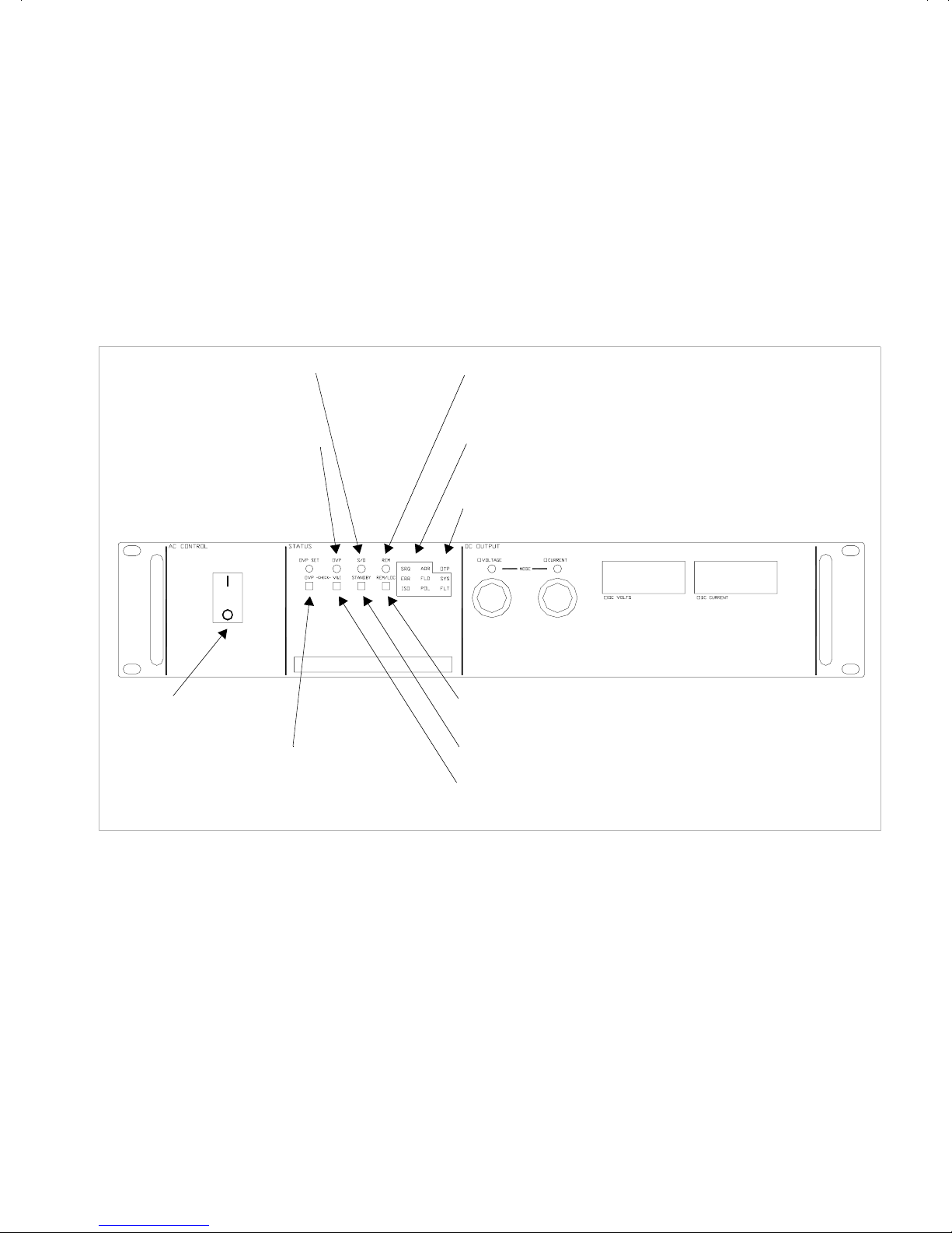
Front Panel Controls
See Figure 1.1 to review the controls, LEDs, and meters located on the power
supply’s front panel. Check the following sections for additional descriptions of front
panel controls and functions.
• “Mechanical Specifications” on page 25
• “Functional Tests” on page 35
• Section 3, “Operation”
Features and Specifications
Front Panel Controls
Shutdown LED (S/D)
Indicates when S/D is activated
by an external S/D signal
Over Voltage LED (OVP)
Indicates when the output
voltage exceeds the limit set
AC Power Switch
Local OVP Setting Preview
Switch (OVP CHECK)
Remote LED (REM)
Indicates that the unit is in remote mode
Remote Programming LEDs
(for units with optional programming interface installed)
Over Temperature LED (OTP)
Remote/Local Switch (REM/LOC)
Forces Unit into Remote or Local Mode
Standby Switch (STANDBY)
Local Voltage and Current Limit
Setting Preview Switch (V&I CHECK)
Figure 1.1 Power Supply Front Panel
Revision A 19
Features and Specifications
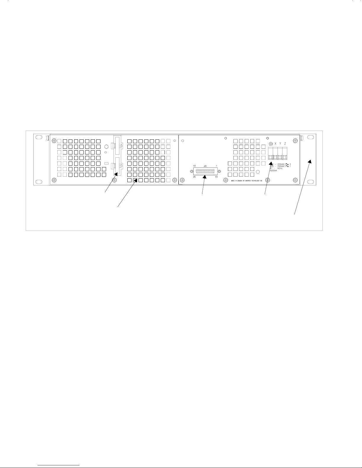
Rear Panel Connectors and Switch
Rear Panel Connectors and Switch
The input AC power, output DC power, as well as the remote program sense and
monitor connector are located on the rear panel. The program and monitor function
selector switch (SW1) is located internally on the main PCB. See Figure 1.2, on page
20 for locations. Refer to Section 2, “Installation” for detail on procedures for
connections and settings.
DC Output Busbars
Ventilation Outlets
Figure 1.2 Power Supply Rear Panel
J3 Program, Sense and
Monitor Connector
AC Input
Terminal Block
Allow Adequate Clearance on
Sides for Ventilation
20 Operating Manual for XKW 3kW Series Power Supply

Specifications
Features and Specifications
Specifications
Electrical
These specifications are warranted over a temperature range of 0 °C to 50 °C.
Specifications
Specifications are subject to change without notice.
Table 1.2 Electrical Specifications for 8 V to 40 V Models
Models 8-350 10-300 12-250 20-150 40-75
Output Ratings:
Output Voltage
Output Current
Output Power
Line Regulation:
1
Voltage
Current
Load Regulation:
2
Voltage
Current
Meter Accuracy:
Voltage
Current
OVP Adjustment Range: 0.4-8.8 V 0.5-11 V 0.6-13.2 V 1-22 V 2-44 V
Output Noise and Ripple:
(20 Hz - 20 MHz)
Voltage (p-p)
Voltage (rms)
0-8 V
0-350 A
2800 W
8mV
350 mA
8mV
350 mA
0.09 V
4.5 A
100 mV
12 mV
0-10 V
0-300 A
3000 W
10 mV
300 mA
10 mV
300 mA
0.11 V
4.0 A
100 mV
15 mV
0-12 V
0-250 A
3000 W
12 mV
250 mA
12 mV
250 mA
0.13 V
3.5 A
100 mV
15 mV
0-20 V
0-150 A
3000 W
20 mV
150 mA
20 mV
150 mA
0.2 V
1.6 A
100 mV
15 mV
0-40 V
0-75 A
3000 W
40 mV
75 mA
40 mV
75 mA
0.5 V
0.85 A
150 mV
20 mV
Analog Programming Accuracy
Voltage (1% of Vmax)
Current (1% of Imax)
3
Drift:
Voltage
Current
Temperature Coefficient:
4
Voltage
Current
1. For input voltage variation over the AC input voltage range, with constant rated load.
2. For 0-100% load variation, with constant nominal line voltage.
3. Maximum drift over 8 hours with constant line, load and temperature, after 90 minute warm-up.
4. Change in output per °C change in ambient temperature, with constant line and load.
Revision A 21
80 mV
3500 mA
4mV
175 mA
1.6 mV
105 mA
100 mV
3000 mA
5mV
150 mA
2mV
90 mA
120 mV
2500 mA
6mV
125 mA
2.4 mV
75 mA
200 mV
1500 mA
10 mV
75 mA
4mV
45 mA
400 mV
750 mA
20 mV
37.5 mA
8mV
22.5 mA

Features and Specifications
Specifications
Table 1.3 Electrical Specifications for 55 V to 300 V Models
Models 55-55 60-50 80-37 150-20 300-10
Output Ratings:
Output Voltage
Output Current
Output Power
Line Regulation:
Voltage
Current
Load Regulation:
Voltage
Current
1
2
0-55 V
0-55 A
3025 W
55 mV
55 mA
55 mV
55 mA
0-60 V
0-50 A
3000 W
60 mV
50 mA
60 mV
50 mA
0-80 V
0-37 A
2960 W
80 mV
37 mA
80 mV
37 mA
0-150 V
0-20 A
3000 W
150 mV
20 mA
150 mV
20 mA
0-300 V
0-10 A
3000 W
300 mV
10 mA
300 mV
10 mA
Meter Accuracy:
Voltage
Current
0.65 V
0.65 A
0.7 V
0.6 A
0.9 V
0.47 A
1.6 V
0.30 A
3.1 V
0.20 A
OVP Adjustment Range: 2.75-60.5 V 3-66 V 4-88 V 7.5-165 V 15-330 V
Output Noise and Ripple:
(20 Hz - 20 MHz)
Voltage (p-p)
Voltage (rms)
150 mV
20 mV
150 mV
20 mV
150 mV
20 mV
200 mV
30 mV
300 mV
30 mV
Analog Programming Accuracy
Voltage (1% of Vmax)
Current (1% of Imax)
3
Drift:
Voltage
Current
Temperature Coefficient:
4
Voltage
Current
1. For input voltage variation over the AC input voltage range, with constant rated load.
2. For 0-100% load variation, with constant nominal line voltage.
3. Maximum drift over 8 hours with constant line, load and temperature, after 90 minute warm-up.
4. Change in output per °C change in ambient temperature, with constant line and load.
550 mV
550 mA
27.5 mV
27.5 mA
11 mV
16.5 mA
600 mV
500 mA
30 mV
25 mA
12 mV
15 mA
800 mV
370 mA
40 mV
18.5 mA
16 mV
11.1 mA
1.5 V
200 mA
75 mV
10 mA
30 mV
6.0 mA
3.0 V
100 mA
150 mV
5mA
60 mV
3.0 mA
22 Operating Manual for XKW 3kW Series Power Supply

Ad ditional
Specifications
Features and Specifications
Specifications
Input
Conditions
Rise Time (No Load, Full Load):
Fall Time (No Load):
Fall Time (Full Load):
1
1
Voltage Mode Transient Response:
Time Delay from power on until
1
~ 30 ms
~ 1 s
~ 50 ms
2
1ms
5 s maximum
output stable
1. Measured with stepped 0-10 V analog programming source and a resistive load.
2. Time for the output voltage to recover within 1% band for 30% step load change from
70% to 100% or 100% to 70%.
Rated AC Input Voltage with
Maximum Input Current
200-250 Vac at 26 Arms, single phase
or 190-250 Vac at 14 Arms, three phase
Maximum AC Input Power 3800 W
Operational AC Input Voltage 200-250 Vac or 190-250 Vac
Input Frequency Range 47-63 Hz
Additi onal
Features
Power Factor 0.65 or better
Switching Frequency Nominal 30 kHz, 60 kHz output ripple
Maximum Voltage Differential from
±400 Vdc
either output to safety ground
Revision A 23

Features and Specifications
Specifications
Remote
Programming
and
Monitoring
Remote Start/Stop and Interlock TTL compatible input. Contact Closure,
Remote Analog Programming Voltage and current programming:
12-250 Vac or 12-130 Vdc
0-5k resistances; 0-5V, 0-10V sources; 0-1mA
sources
OVP programming:
0-5V, 0-10V sources
Environmental
Specification
Maximum Remote Sense Line Drop
Compensation
Operating Temperature Range 0-50 °C. From 50-70 °C, derate output 2% per °C
Storage Temperature Range -55 °C to +85 °C
Humidity Range Up to 80% non-condensing
Operating Altitude Derate maximum operating temperature by 1°C
Storage Altitude Up to 50,000 feet (15,000 m)
Installation Category II
Pollution Degree 2
1V max.
per 1,000 feet (30 m) for operation between
5,000 feet and (1,500 m) and 15,000 feet
(4,500 m)
24 Operating Manual for XKW 3kW Series Power Supply

Mechanical
Specifications
Features and Specifications
Specifications
Front Panel V and I Control 10-turn voltage and current potentiometers
Front Panel Voltage Control
0.02% of V max
Resolution
Front Panel Voltage and Current
Meters
3 or 4 digit LED readouts for each.
See Table 1.2 and Table 1.3 for accuracy.
AC Input Connector Type IEC
Output Connector Nickel-plated copper busbars
Sense Connector Part of J3
Analog Programming Connector Part of J3
Cooling Fan cooled. Air exhausts to rear. Over temperature
shutdown: automatic restart.
Mounting Integral rack mount ears on front panel
Dimensions 3.45 in. (87.6 mm) H x 19 in. (482.6 mm) W x
20 in. (508 mm) D
Weight Approximately 35 lb. (16 kg)
Approvals CSA Certified to CSA Bulletin 556B
FCC Part 15B and Industry Canada Class A
CE Marked for Low Voltage Directive and EMC
Directive (Class A emissions)
Revision A 25

Features and Specifications
Specifications
26 Operating Manual for XKW 3kW Series Power Supply

Section 2. Installation
Introduction
This section provides recommendations and procedures for inspecting, installing,
and testing the power supply.
Basic Setup Procedure
See Table 2.1 for a summary of the basic setup procedure and an overall view of the
subsections in Section 2. Use the procedure as a quick reference if you are familiar
with the installation requirements for the power supply. If you want more
information, each step in the procedure refers to subsequent sections which contain
more details. Execute each step in the sequence given.
Table 2.1 Basic Setup Procedure
Step # Description Action Reference
1 Safety Read and follow safety
recommendations
2 Inspection Perform an initial physical
inspection of the supply.
3 Installation Install the supply (bench or rack
mount), ensuring adequate
ventilation.
4 Input Power Connect AC input power. “AC Input Power” on
“Inspection, Cleaning, and
Packaging” on page 28
“Inspection, Cleaning, and
Packaging” on page 28
“Location, Mounting and
Ventilation” on page 31
page 32
5 Test Perform functional tests for
voltage mode operation, current
mode operation, and front panel
controls.
6 Load Connect the load. “Load Connection” on
“Functional Tests” on
page 35
page 37
7 Sensing Connect sensing lines. “Local and Remote
Sensing” on page 43
See Section 3, “Operation” for instructions about front panel operation, OVP, OTP,
shutdown, and using multiple supplies. You will also find remote programming and
monitoring described in the same section.
Revision A 27

Installation
Inspection, Cleaning, and Packaging
Inspection, Cleaning, and Packaging
Initial
Inspection
Periodic
Cleaning
When you first receive your unit:
1. Inspect the unit for scratches and cracks, and for broken switches, connectors,
and displays.
2. Have the service technician check the printed circuit board and its components
if you suspect internal damage.
If the unit is damaged, save all packing materials and notify the carrier immediately.
See packing instructions on page 29.
No routine servicing of the power supply is required except for periodic cleaning.
Whenever a unit is removed from operation, clean metal surfaces with naphtha or an
equivalent solvent and the front panel with a weak solution of soap and water. Use
low-pressure compressed air to blow dust from in and around components on the
printed circuit boards.
28 Operating Manual for XKW 3kW Series Power Supply

Returning Power Supplies to the Manufacturer
Installation
Returning Power Supplies to the Manufacturer
Return
Material
Authorization
Policy
Before returning a product directly to Xantrex you must obtain a Return Material
Authorization (RMA) number and the correct factory “Ship To” address. Products
must also be shipped prepaid. Product shipments will be refused and returned at your
expense if they are unauthorized, returned without an RMA number clearly marked
on the outside of the shipping box, if they are shipped collect, or if they are shipped
to the wrong location.
When you contact Xantrex to obtain service, please have your operating manual
ready for reference and be prepared to supply:
• The serial number of your product
• Information about the installation and use of the unit
• Information about the failure and/or reason for the return
• A copy of your dated proof of purchase
When you ship:
1. Package the unit safely following the procedures on page 30, preferably using
the original box and packing materials. Please ensure that your product is
shipped fully insured in the original packaging or equivalent. This warranty will
not apply where the product is damaged due to improper packaging.
2. Include the following:
• The RMA number supplied by Xantrex Technology Inc clearly marked on
the outside of the box.
• A return address where the unit can be shipped. Post office boxes are not
acceptable.
• A contact telephone number where you can be reached during work hours
• A brief description of the problem
Ship the unit prepaid to the address provided by your Xantrex customer service
representative.
If you are returning a product from outside of the USA or Canada:
In addition to the above, you MUST include return freight funds and are fully
responsible for all documents, duties, tariffs, and deposits.
If you are returning a product to a Xantrex Authorized Service Center (ASC):
A Xantrex return material authorization (RMA) number is not required. However,
you must contact the ASC prior to returning the product or presenting the unit to
verify any return procedures that may apply to that particular facility.
Revision A 29

Installation
Returning Power Supplies to the Manufacturer
Packaging for
Shipping or
Storage
Follow these instructions to prepare the unit for shipping or storage.
1. When returning the unit or sending it to the service center, attach a tag to the unit
stating its model number (available from the front panel label) and its serial
number (available from the rear panel label). Give the date of purchase and an
invoice number, if you have it, as well as a brief description of the problem.
2. For storage or shipping, repack the power supply in its original container. If the
original container is not available, seal the unit in a plastic bag and then pack it
in a 200 lb. (90 kg) test, corrugated cardboard carton large enough to allow 2
inches (5 cm) of cushioning material to surround the unit. Use a material such as
foam slabs or chips.
3. Label the carton as shown in Figure 2.1.
4. If shipping, mark the address of the service center and your return address on the
carton.
5. If storing, stack no more than eight cartons high. Check the storage temperature
range and storage altitude specification in “Environmental Specification” on
page 24.
POWER SUPPLY
Model Number: _______________________
Serial Number: _______________________
FRAGILE — ELECTRONIC EQUIPMENT
Figure 2.1 Shipping or Storage Carton Label
30 Operating Manual for XKW 3kW Series Power Supply

Location, Mounting and Ventilation
Installation
Location, Mounting and Ventilation
V entilation
Requirements
Rack
Mounting
Bus Bar
Cover
The power supply may be used in rack mounted or benchtop applications. In either
case, sufficient space must be allowed for cooling air to reach the ventilation inlets
in the top and on each side of the unit and for the fan exhaust air to exit from the rear
of the unit.
The power supply is designed to fit in a standard 19 in. equipment rack. Bolt holes
in the chassis sides are provided for rack mount slides such as the ZERO #C300S18
slides. When installing the unit in a rack, be sure to provide adequate support for the
rear of the unit while not obstructing the ventilation inlets on the sides of the unit.
An optional busbar cover is available for bench-top power supplies. This will guard
against injury from the exposed bus-bars at voltages above 42 Vdc. Rack mounted
supplies are already protected.
Revision A 31

Installation
!
AC Input Power
AC Input Power
WARNING
There is a potential shock hazard if the power supply chassis and cover are not
connected to an electrical ground via the safety ground in the AC input connector.
Ensure that the power supply is connected to a grounded AC outlet with the
recommended AC input connector configured for the available voltage as described
in this section.
WARNING
Disconnect AC power from the unit before removing the cover. Even with the
front panel power switch in the OFF position, live line voltages are exposed
when the cover is removed. Repairs must be made by experienced service
technicians only.
CAUTION
When the power switch is turned ON, output voltage or current previously
set will be applied to loads.
AC Input
Connector
and Voltage
Selection
AC Input
Cord
The AC input connector is a 4-terminal wire clamp located on the power supply’s
rear panel. Operate the power supply with either a single phase or three phase AC
power source. Check the specifications in the table below for input voltage, current,
and frequency.
AC Voltage Range Maximum Input Current Frequency
200-250 Vac, 1 φ 26 Arms 47-63 Hz
190-250 Vac, 3 φ 14 Rms 47-63 Hz
WARNING
The AC input cord is the disconnect device for the power supply. The plug must
be readily identifiable by and accessible to the operator. The input cord must be
no longer that 9.84 feet (3 m).
32 Operating Manual for XKW 3kW Series Power Supply

Installation
AC Input Power
The AC input cord we recommend is specified in the table below. Add a non-locking
plug suitable for use in the country in which you are operating. If you require a
special cord, please contact the manufacturer.
Wire Size Ratings Cable Outside Diameter
AC Input Wire
Connection
3 x 12 AWG stranded copper
(1 φ)
4 x 12 AWG stranded copper
(3 φ)
WARNING
Wear protective gloves and use caution when removing the circular knockout
from the cover as described below. The exposed metal edges of the knockout
may be sharp.
60 °C minimum, 300 V 0.545-0.708 in.
(13.63-17.7 mm)
60 °C minimum, 300 V 0.545-0.708 in.
(13.63-17.7 mm)
The power supply is shipped with a protective cover for the AC input connector. As
long as the screw-holes on the AC input cover and the standoffs on the unit align, the
cover may be installed at any orientation. To prepare and connect the AC input
wiring, follow these steps:
1. Use a gloved finger or a blunt tool to push in the circular knockout on the cover
that is preferred for your system setup. After you push in the knockout, twist it
until it detaches from the cover, and throw it away.
2. Strip the outside insulation on the AC cable approximately 2 in. (5 cm). Strip
0.25 in. (6 mm) at the end of each of the wires. See Figure 2.2, on page 34 for
details.
3. Unscrew the base of the strain relief from the helix-shaped body. Insert the base
through the outside opening in the AC input cover and, from the inside, screw
the locknut securely onto the base.
4. Slide the helix-shaped body onto the AC cable. Insert the stripped wires through
the strain relief base until the outer cable jacket is flush with the edge of the base.
Tighten the body to the base while holding the cable in place. The cable is now
securely fastened inside the strain relief.
5. Route the AC wires to the input connector terminals as required. For input
connector terminal locations, see the label on the rear panel of the unit and Tabl e
2.2, on page 34. To connect the wiring, loosen the terminal screw, insert the
stripped wire into the terminal, and tighten the screw securely.
Revision A 33

Installation
AC Input Power
6. Route the wires inside the cover to prevent pinching. Fasten the AC input cover
to the standoffs on the unit using the 6-32 x 2 in. (2) screws, flat washers, and
lock washers provided.
Input Line
Impedance
Figure 2.2 Stripped Wire Installed in Strain Relief
Table 2.2 AC Connections for Single and Three Phase Input
Phase Ground X Terminal Y Terminal Z Terminal
Single phase E L N
Three phase E L L L
The maximum input line impedance for operation at full rated output is 1 ohm.
Higher source impedances can be tolerated by raising the input line voltage or by
reducing the output voltage and/or current.
34 Operating Manual for XKW 3kW Series Power Supply

Functional Tests
Before connecting the unit to an AC outlet, make sure that the power switch is in the
OFF position and that the voltage and current controls are turned fully counter
clockwise. Check that the J3 mating connector on the rear of the unit is in place with
jumpers connected for local operation as shown below. (This is the default
configuration as shipped from the factory). Connect the unit to a 230 Vac grounded
outlet and switch the unit on. After a short power on delay the front panel meters
should light up with both displays reading zero.
Figure 2.3 Connector J3 Configuration for Local Operation
Installation
Functional Tests
Voltage Mode
Operation
To check voltage mode operation, proceed as follows:
1. Connect a DVM, rated better than 0.5% accuracy, to the rear output terminals,
observing correct polarity.
2. Rotate the CURRENT control 1/2 turn clockwise. Slowly rotate the VOLTAGE
control clockwise and observe both the internal and external meters. Minimum
control range should be from zero to the maximum rated output. Compare the
test meter reading with the front panel voltmeter reading. Check that the green
voltage mode indicator led is ON.
3. Set the POWER switch to OFF.
Revision A 35

Installation
Functional Tests
Current Mode
Operation
Front Panel
Function
Checks
To check current mode operation, proceed as follows:
1. Rotate the VOLTAGE and CURRENT controls fully counterclockwise.
2. Rotate the VOLTAGE control 1/2 turn clockwise.
3. Connect a high current DC ammeter
1
across the rear output terminals, observing
correct polarity. Select leads of sufficient current carrying capacity and an
ammeter range compatible with the unit's rated current output. The ammeter
should have an accuracy of better than 0.5%.
4. Set the POWER switch to ON.
5. Rotate the CURRENT control slowly clockwise. The control range should be
from zero to the maximum rated output. Compare the test meter reading with the
reading on the front panel ammeter. Check that the red current mode indicator
led is ON.
6. Set the POWER switch to OFF.
1. Press OVP CHECK switch and check that the voltmeter displays approximately
the model-rated output voltage plus 10%.
2. Turn OVP SET potentiometer counter-clockwise and check that the voltmeter
reading decreases. Continued turning (up to 20 turns) will see the reading
decrease to approximately 5% of the model-rated voltage output. Turn the
potentiometer clockwise until the voltmeter once again displays approximately
the model-rated output voltage plus 10%.
3. With voltage and current controls turned all the way in a clockwise direction,
press the V & I CHECK switch and check that the voltmeter and ammeter
display a minimum of the power supply model output ratings.
4. With voltage and current controls turned all the way in a clockwise direction,
push the STANDBY switch to its IN position and check that the voltmeter
reading falls to zero and the S/D (Shutdown) LED illuminates. Push the
STANDBY switch once again to reset it to its OUT position. The S/D LED will
turn off.
5. Push REM/LOC switch to IN position and check that the REM LED illuminates
and the voltmeter reading falls to zero. Reset the REM/LOC switch to its OUT
position for local (default) operation.
1. Either a direct reading meter or calibrated meter and shunt combination.
36 Operating Manual for XKW 3kW Series Power Supply

Controls, Connectors, and Indicators
!
CAUTION
All remote programming input and monitoring lines are internally referenced to the
supply’s negative output. Do not reference remote programming or monitor lines to
the supply’s positive output. J3 pin 6 (ground) is directly connected to the supply’s
negative output. Do not connect this pin to the positive output or to the chassis.
Please refer to Figure 1.1, “Power Supply Front Panel” on page 19 for front panel
controls and indicators, Figure 1.2, “Power Supply Rear Panel” on page 20 for rear
panel connectors and switch details, and to Figure 3.1, “J3 Program, Sense, and
Monitor Connector Description” on page 49 for a description of the J3 Program,
Sense, and Monitor Connector.
Note: J3 pins 1, 2, and 14 form an isolated control function and may be biased
relative to the supply output
Installation
Controls, Connectors, and Indicators
Load Connection
Reliable performance of the power supply can be obtained if certain basic
precautions are taken when connecting it for use on the lab bench or installing it in
a system.
To obtain a stable, low noise output, careful attention should be paid to factors such
as conductor ratings, system grounding techniques and the way in which the load and
remote sensing connections are made.
Revision A 37

Installation
Load Connection
Load
Conductor
Ratings
Load Wiring
Length for
Operation
with Sense
Lines
As a minimum, load wiring must have a current capacity greater than the output
current rating of the power supply. This ensures that the wiring will not be damaged
even if the load is shorted. Ta ble 2. 3 shows the maximum current rating, based on
2
450 A/cm
, for various gauges of wire rated for 105 °C operation. Operating at the
maximum current rating results in an approximately 30 °C temperature rise for a
wire operating in free air. Where load wiring must operate in areas with elevated
ambient temperatures or bundled with other wiring, use larger gauges or wiring rated
for higher temperatures.
Table 2.3 Current Carrying Capacity for Load Wiring
Wire Size
(AWG)
20 2.5 6 61
18 4 4 97
16 6 2 155
14 10 1 192
12 16 1/0 247
10 21 2/0 303
836
Maximum Current (A)
Wire Size
(AWG)
Maximum Current (A)
For applications using remote sensing, the voltage drop across each load line must
be limited to 1V or less. Figure 2.4, shows the maximum allowable wire length that
may be used for a given load current and wire size to ensure that this limit is not
exceeded.
Figure 2.4 Maximum Load Wire Length
38 Operating Manual for XKW 3kW Series Power Supply

Installation
!
Load Connection
Noise and
Impedance
Effects
Making the
Connections
To minimize noise pickup or radiation, use shielded-twisted pair wiring of as short a
length as possible for load wires. Connect the shield to the chassis via a rear panel
mounting screw. Where shielding is impossible or impractical, simply twisting the
wires together will offer some noise immunity. When using local sense connections,
use the largest practical wire size to minimize the effects of load line impedance on
the regulation of the supply.
CAUTION
When making connections to the bus bars, ensure each terminal's mounting
hardware and wiring assembly is placed to avoid touching the other terminal and
shorting the power supply output. Heavy connecting cables must have some form of
strain relief to avoid loosening the connections or bending the bus bars.
Make load connections to the power supply at the positive and negative output
terminals (or bus bars) at the rear of the power supply. See Figure 1.2, “Power
Supply Rear Panel” on page 20. The power supply provides three load wiring
mounting holes on each bus bar terminal as specified in the following table.
Load Wiring Mounting
Holes
Diameter Hardware Size
Connecting
Single Loads
One (1) per terminal 0.332 in.
Two (2) per terminal
0.190 in. on 0.5 in. centers #10
1/4 in.
(5/16 in. for 8V + 12V models)
Figure 2.5 and Figure 2.6 show recommended load and sensing connections for
single loads. Local sense lines shown are default J3 connections. Refer to
“Connecting Remote Sensing Lines” on page 44 for more information about the
sense line shield.
Revision A 39

Installation
Load Connection
LOAD LINES
USE THE LARGEST GAUGE
AND SHORTEST LENGTH
POSSIBLE
POSITIVE SENSE
POSITIVE OUTPUT
TERMINAL
OUTPUT RETURN
TERMINAL
RETURN SENSE
POWER SUPPLY
Figure 2.5 Single Load with Local Sensing (Default)
USE THE LARGEST GAUGE
AND SHORTEST LENGTH
POSITIVE SENSE
POSITIVE OUTPUT
TERMINAL
OUTPUT RETURN
TERMINAL
RETURN SENSE
POSITIVE LOAD
TERMINAL
NEGATIVE LOAD
TERMINAL
LOAD
LOAD LINES
POSSIBLE
POSITIVE LOAD
TERMINAL
NEGATIVE LOAD
TERMINAL
POWER SUPPLY
Figure 2.6 Single Load with Remote Sensing
40 Operating Manual for XKW 3kW Series Power Supply
SEE SECTION 3.3 FOR
REMOTE SENSE LINE
CONNECTION PROCEDURE
LOAD

Load
Connection
and
Grounding
Installation
Load Connection
WARNING
Exercise caution when using and servicing power supplies. High energy levels can
be stored at the output voltage terminals on all power supplies in normal operation. In
addition, potentially lethal voltages exist in the power circuit and the output connector
of power supplies which are rated at 40V and over. Filter capacitors store potentially
dangerous energy for some time after power is removed.
Proper connection of distributed loads is an important aspect of power supply
application. A common mistake is to connect leads from the power supply to one
load, from that load to the next load, and so on for each load in the system. In this
parallel power distribution method, the voltage at each load depends on the current
drawn by the other loads and DC ground loops are developed. Except for low current
applications, this method should not be used.
The preferred way to distribute power is by the radial distribution method in which
power is connected to each load individually from a single pair of terminals
designated as the positive and negative distribution terminals. The pair of terminals
may be the power supply output terminals, the terminals of one of the loads or a
distinct set of terminals especially established for distribution. Connecting the sense
leads to these terminals will compensate for losses and minimize the effect of one
load upon another.
Inductive Loads To prevent damage to the power supply from inductive
kickback, connect a diode (rated at greater than the supply’s output voltage and with
a current surge rating greater than or equal to the supply’s output current rating)
across the output. Connect the cathode to the positive output and the anode to return.
Where positive load transients such as back EMF from a motor may occur, connect
a transorb or a varistor (with a breakdown voltage approximately 10% higher than
the rated supply output) across the output to protect the power supply.
Revision A 41

Installation
Load Connection
POSITIVE SENSE
POSITIVE OUTPUT
TERMINAL
OUTPUT RETURN
TERMINAL
RETURN SENSE
LOAD LINES
USE THE LARGEST GAUGE
AND SHORTEST LENGTH
POSSIBLE
POSITIVE LOAD
TERMINAL
NEGATIVE LOAD
TERMINAL
POWER SUPPLY
LOAD LINES
USE THE LARGEST GAUGE
AND SHORTEST LENGTH
POSSIBLE
Figure 2.7 Multiple Loads with Local Sensing
SEE SECTION 3.3 FOR
REMOTE SENSE LINE
CONNECTION PROCEDURE
POSITIVE SENSE
POSITIVE OUTPUT
TERMINAL
OUTPUT RETURN
TERMINAL
RETURN SENSE
POSITIVE
DISTRIBUTION
TERMINAL
POSITIVE LOAD
NEGATIVE LOAD
LOAD 1
POSITIVE LOAD
TERMINAL
NEGATIVE LOAD
TERMINAL
LOAD 2
TERMINAL
TERMINAL
POWER SUPPLY
Figure 2.8 Multiple Loads with Remote Sensing
42 Operating Manual for XKW 3kW Series Power Supply
NEGATIVE
DISTRIBUTION
TERMINAL
LOAD LINES
USE THE LARGEST GAUGE
AND SHORTEST LENGTH
POSSIBLE
LOAD 1
POSITIVE LOAD
TERMINAL
NEGATIVE LOAD
TERMINAL
LOAD 2

Local and Remote Sensing
Installation
Local and Remote Sensing
Local
Programming
Mode
Operation
Local Mode
Default
Configuration
Units are shipped from the factory configured for local programming mode
operation.
• Output voltage and current limit settings are adjusted with the front panel
controls.
• The sense point of the supply is at the output terminals.
• The front panel OVP potentiometer determines the OVP set point. See “Using
Over Voltage Protection (OVP)” on page 62 for the adjustment procedure.
Figure 2.9 shows the default factory settings for the internal jumpers JMP1 and
JMP2, for switch SW1, and for rear panel connector J3. These controls are used to
select among the various options for programming, sensing, and monitoring. See
“Configuring for Remote Programming, Sensing, and Monitoring” on page 48.
C
B
A
JMP 1
C
B
A
JMP 2
8 7 6 5 4 3 2 1
Figure 2.9 Local Mode Default Configuration
Setting
Output
Voltage and
After installing the power supply and connecting the load, set the required output
voltage and current limit according to the following front panel procedure:
1. Turn both the voltage and current controls fully counter-clockwise.
Current Limit
2. Turn the AC power ON.
3. Press the STANDBY switch to its IN position to disable the power supply
output.
4. Press and hold the V & I CHECK button to display the voltage and current
control settings on the voltmeter and ammeter displays.
5. Adjust the voltage control to the required voltage (the compliance voltage for
applications using current mode operation).
6. Adjust the current control to the required current limit setting.
7. Release the V & I CHECK button.
Revision A 43

Installation
!
Using Remote Sensing
8. Press the STANDBY switch to its OUT position to apply power to the load.
Using Remote Sensing
CAUTION
Do not use remote sensing with multiple supplies connected in series or in parallel.
Remote sensing is used during voltage mode operation to shift the power supply's
regulation point from its output terminals (default sense point) to the load or
distribution terminals by using a separate pair of wires to monitor the load voltage.
Remote sensing allows the power supply to compensate for voltage losses in the load
lines (up to 1V per line) which will otherwise degrade the regulation of the supply.
The sense line connection points are located on the rear panel J3 connector.
“Configuring for Remote Programming, Sensing, and Monitoring” on page 48 has
more information about making J3 connector changes.
Connecting
Remote
Sensing
Lines
Sense wires can be any size (24 AWG or larger) but in high noise environments or
when the lowest possible power supply ripple is required, sense wires must be
twisted and/or shielded.
To connect remote sense lines, refer to Figure 2.10 and to the following procedure:
1. Ensure the power supply is turned OFF. Allow five (5) minutes to elapse to
dissipate stored energy before altering J3 connector pin connections.
2. Remove the local sense jumpers connecting J3 pins 13 to 25 (positive sense) and
pins 12 to 24 (negative sense or return sense).
3. Connect the positive sense lead to pin 13 and the negative lead to pin 12. Use
shielded-twisted pair wiring of 24 AWG or larger for sense lines.
4. Ground the sense line shield, at one point only, to the power supply's return
output connection at the load, or, to the power supply's return output at its output
terminal, or to the power supply's chassis.
5. The optimal point for the shield ground must be determined by experiment, but
the most common connection point is at the power supply's return output
connection at the load.
6. Turn the power supply ON.
Notes:
• If the power supply is operated with remote sense lines connected and with either
of the positive or negative load lines not connected, the power supply shutdown
circuit will be activated, causing the output voltage and current to fall to zero.
44 Operating Manual for XKW 3kW Series Power Supply

Installation
Using Remote Sensing
• If the power supply is operated without remote sense lines or local sense
jumpers in place, the supply will continue to work, but supply regulation will be
degraded and/or erratic.
NEG
POWER SUPPLY
OUTPUT
TERMINAL
POS
SNS
SNS
12
J3
POWER SUPPLY
POSITIVENEGATIVE
113
OUTPUT
TERMINAL
POSITIVE
SENSE WIRE
SENSE LINE
SHIELD
NEGATIVE
OUTPUT
LOAD WIRE
GROUND SHIELD IN
ONE LOCATION ONLY
(SEE TEXT FOR
ALTERNATE
LOCATIONS)
-SNS +SNS
-+
LOAD
Figure 2.10Connecting Remote Sense Lines
NEGATIVE
SENSE WIRE
14
POSITIVE
OUTPUT
LOAD WIRE
Revision A 45

Installation
Using Remote Sensing
46 Operating Manual for XKW 3kW Series Power Supply

Section 3. Operation
Introduction
All power supplies in this series offer the following features as part of their standard
configuration.
Feature Reference
Accessing
Advanced
Features
Remote Programming of Output Voltage and Current Limit with 0-5V,
0-10V, 0-1mA, and 0-5k ohms
Overvoltage Protection (OVP) with front panel controls or 0-5V and
0-10V programming
Programmable Shutdown with AC, DC, or TTL compatible signals and
contact closure
Remote Monitoring of Status Indicators for thermal shutdown, OVP
status, remote/local programming mode, and voltage/current mode
operation
Calibrated Readback Signals for output voltage and output current with
selectable 0-5V or 0-10V scales
Multiple Supply Configurations such as series, parallel, and split
supplies
page 54
page 62
page 65
page 72
page 72
page 73
Accessing these features may require that you use one or more of the following
procedures:
• Using the front panel REM/LOC (Remote/Local Programming) switch.
• Reconfiguring the rear panel J3 connector.
• Making connections to the J3 connector.
• Resetting internal jumpers JMP1 and JMP2.
• Resetting internal switch SW1.
“Configuring for Remote Programming, Sensing, and Monitoring” on page 48
provides a reference to the function and location of these controls, and procedures
for making any required changes.
Revision A 47

Operation
Configuring for Remote Programming, Sensing, and Monitoring
Configuring for Remote Programming, Sensing, and Monitoring
This section lists switch, connector, and jumper functions for the power supply.
Subsequently, it provides a location diagram, gives procedures for resetting the
internal jumpers and switches, and covers reconfiguring or making connections to
the J3 connector.
You will find remote programming procedures and diagrams covered in more detail
in “Remote Programming of Output Voltage and Current Limit” on page 54, remote
sensing in “Local and Remote Sensing” on page 43, and remote monitoring of
readback signals and status indicators in “Remote Monitoring of Readback Signals
and Status Indicators” on page 72.
Programming,
Monitoring,
and Control
Functions
Front Panel REM/LOC Switch You can use the REM/LOC (Remote/Local
Programming) switch for remote programming. When set to REM (Remote
Programming), control of BOTH output voltage AND current limit is passed to
external voltage and/or current sources which are connected to the J3 connector.
Resetting the switch to LOC returns the supply to local (front panel) control. See
“Remote Programming of Output Voltage and Current Limit” on page 54 for more
information about using this switch.
External J3 Connector
The external J3 connector provides user access to the following functions:
• Remote programming of output voltage OR current limit, and for OVP
• Remote monitoring of the following readback signals and status indicators
Readback Signals Status Indicators
• Calibrated output voltage
• Calibrated output current
• Thermal shutdown
• OVP circuit
• Remote/local programming mode
• Remote programming of the shutdown function using AC, DC, or TTL
compatible signals
• Remote sensing of output voltage
See Figure 3.1.
48 Operating Manual for XKW 3kW Series Power Supply

Operation
Configuring for Remote Programming, Sensing, and Monitoring
15
NOT USED
15
NOT USED
0-5V AND 0-10V OUTPUT REPRESENTS 0-100% OUTPUT VOLTAGE
CALIBRATED OUTPUT VOLTAGE MONITOR
Figure 3.1 J3 Program, Sense, and Monitor Connector Description
Revision A 49

Operation
Configuring for Remote Programming, Sensing, and Monitoring
Internal Switch and Jumpers If you should need to change any of the standard
configurations of the supply, internal jumpers JMP1 and JMP2, and switch SW1
enable you to select:
• Voltage and Current Programming Scale Factor
• Over Voltage Protection (OVP) Programming Mode and Scale
• Voltage and Current Monitor Range
• Shutdown Circuit Logic
SELECTS OVP
PROGRAMMING RANGE
CLOSED = 0-10V
OPEN = 0-5V
SELECTS SHUTDOWN
CIRCUIT LOGIC
CLOSED = NEGATIVE LOGIC
OPEN = POSITIVE LOGIC
SELECTS OVP
PROGRAMMING MODE
CLOSED = LOCAL
OPEN = REMOTE
SELECTS VOLTAGE
PROGRAMMING INPUT PROGRAMMING INPUT
B-C = 0-5V B-C = 0-5V
A-B = 0-10V A-B = 0-10V
SELECTS VOLTAGE
MONITOR RANGE
CLOSED = 0-5V
OPEN = 0-10V
SW1
OPEN (OFF)
CLOSED (ON)
23456781
SELECTS CURRENT LIMIT
RANGE RANGE
NOT USED
SELECTS CURRENT
MONITOR RANGE
CLOSED = 0-5V
OPEN = 0-10V
NOT USED
CC
BB
AA
JMP2JMP1
Figure 3.2 Internal Jumpers and Switch (Default Settings Shown)
50 Operating Manual for XKW 3kW Series Power Supply

Operation
Configuring for Remote Programming, Sensing, and Monitoring
Locating
Jumpers,
Switch, and
Connector
Switch SW1 and jumpers JMP1 and JMP2 are located on the main printed circuit
board (A2) inside the power supply. “Resetting Jumpers and Switch” on page 51
provides a procedure for removing the power supply cover and changing jumper and
switch settings. The J3 connector is located on the unit's rear panel. “Making J3
Connections” on page 53 provides a procedure for changing connections to the J3
connector.
FRONT PANEL
1
2
3
JMP2JMP1
4
5
6
7
8
CLOSED
(ON)
SW1
Resetting
Jumpers and
Switch
AA
BB
CC
REAR PANEL
A2 PCB
J3 CONNECTOR
PROGRAM, SENSE AND
MONITOR CONNECTOR
Figure 3.3 Locating Jumpers, Switch, and Connector
Most applications will use the default factory settings of the internal jumpers, JMP1
and JMP2, or of the internal 8-position DIP switch, SW1. If the jumpers and switch
should require resetting, follow the procedures in this section.
The steps to follow are:
• Dissipating stored energy
• Removing the cover
• Removing the option board (when required)
• Resetting JMP1, JMP2 and SW1
• Replacing the option board
• Replacing the cover
• Powering up
Revision A 51

Operation
!
Configuring for Remote Programming, Sensing, and Monitoring
Dissipating Stored Energy
1. Ensure the power supply is turned OFF. Disconnect the AC input connector.
Allow five (5) minutes to elapse to dissipate stored energy before removing the
cover.
Removing the Cover
CAUTION
If you should remove the unit's cover, use proper static control techniques to avoid
damage to static-sensitive digital components on the printed circuit board.
2. Unscrew and remove the eight (8) flathead Philips screws from the top of the
cover: two (2) are located near the front panel, six (6) near the rear panel. Use a
#1 Philips screwdriver.
3. Loosen but do not remove the six (6) Philips screws located three (3) to a side in
the slots along each side of the power supply.
4. Lift cover off and set aside.
Removing the Option Board (when required) The power supply may have
either of two option circuit boards installed over the A2 circuit board where the
jumpers and switches are located. The option board must be removed to allow access
to them.
5. Unplug any external mating connector and attached wiring.
6. Use a nutdriver to remove the jack screws which fasten the option board to the
rear panel.
7. Unscrew the mounting screws which fasten the option board down.
8. Unplug any attached cables.
9. Lift out the option board and set aside.
Resetting JMP1, JMP2, and SW1
10. Lift the appropriate jumper from its pin header and replace it as the programming
requires. The default location is B-C for both JMP1 and JMP2. Alternate
locations are A-B in each case.
11. Push the dual position SW1 switches closed (ON) or open (OFF) as required by
the application.
12. Place the option board into its original location over the A2 circuit board.
13. Reinstall the mounting screws into the standoffs. Reattach any cables.
52 Operating Manual for XKW 3kW Series Power Supply

Operation
Configuring for Remote Programming, Sensing, and Monitoring
14. Reinstall the jack screws with the nut driver.
15. Reconnect any external cables and connector.
Replacing the Cover
16. Place the cover in its original location.
17. Reinstall the eight (8) flathead Philips screws on the top of the cover, then
tighten the six (6) Philips screws in the side slots.
Powering Up
18. Reconnect the AC input connector. Turn the power supply ON.
Making J3
Connections
Some applications will use only the default factory connections on the J3 connector
located on the rear panel. Other applications will require replacing pin-to-pin
connections or making connections to external devices such as voltage sources,
current sources, or resistance. Follow the procedures in this section whenever the
rear panel connector, J3, is to be reconfigured.
The steps to follow are:
• Dissipating stored energy
• Making the connections
• Powering up
Refer to the “Dissipating Stored Energy” on page 52 and “Powering Up” on page 53.
Making the Connection
To make pin-to-pin connections:
1. Unsolder any pin-to-pin jumpers as required by the application.
2. Solder new connections using any appropriate single bus wire such as AWG 20
to 24.
To connect external source leads, resistance leads, or monitoring or sense lines:
3. Unsolder any jumpers as required by the application.
4. Solder leads to the specified pin using the recommended wiring and/or
grounding point for the application. Pin, wiring, and grounding specifications
for particular applications can be found in this section, except for remote sensing
specifications which are in “Using Remote Sensing” on page 44.
Revision A 53

Operation
!
Remote Programming of Output Voltage and Current Limit
Remote Programming of Output Voltage and Current Limit
CAUTION
The remote programming input is internally referenced to the supply's negative
output. Do not connect remote programming input lines (J3 pins 9 and 10) to the
supply's positive output.
Remote programming allows control of the power supply's output voltage and/or
current limit to shift from local operation at the front panel voltage and current
controls to external analog input sources. As a programming source is varied, the
power supply's output varies proportionally over its output range.
The analog programming signals are connected to the rear panel J3 connector. To
provide the lowest noise performance, use shielded-twisted pair wiring for making
connections from external circuits to the J3 connector. Use the shortest leads
possible. Ground the shield to pin 6 on the J3 connector or to the chassis via one of
the J3 connector screws.
Remote
Programming
Options
The following table summarizes access options for programming output voltage and
current limit with the input scales supported for the power supply. Refer to
“Programming Output Voltage and Current Limit with the REM/LOC Switch” on
page 55 for a procedure and a connection diagram for programming output voltage
and current limit using the REM/LOC switch. Subsequent sections provide short
procedures and diagram the J3 connector configurations and connections required
for remote programming of output voltage and/or current limit without using the
REM/LOC switch.
Table 3.1 Remote Programming Options
Remote Programming Options Control of... Programming Scales
Programming with the
REM/LOC Switch
Programming without
the REM/LOC Switch
1. These scales may be used in any combination.
Output Voltage and
Current Limit
Output Voltage and/or
Current Limit
0-5V
0-1mA
0-10V (see Notes below)
0-5V
0-1mA
0-5k
Local control
0-10V (see Notes below)
1
54 Operating Manual for XKW 3kW Series Power Supply

Operation
Remote Programming of Output Voltage and Current Limit
Notes for Programming with a 0-10V Source:
WARNING
Exercise caution when resetting internal jumpers. Follow the procedures for
removing the cover and resetting jumpers in “Resetting Jumpers and Switch” on
page 51
1. Programming with a 0-10V external voltage source requires that you reset
internal jumpers JMP1 and/or JMP2 in addition to performing any external
operations.
2. Resetting internal jumpers may require a recalibration of the programming
circuit to maintain programming accuracy. See “Calibrating for Programming
Accuracy” on page 82.
“Configuring for Remote Programming, Sensing, and Monitoring” on page 48
explains how to use the front panel REM/LOC switch, how to reconfigure or make
connections to the external J3 connector, and how to access internal jumpers JMP1
and JMP2 to change their settings.
Programming
Output
Voltage and
Current Limit
with the
REM/LOC
Switch
The front panel REM/LOC (Remote/Local Programming) switch will allow you to
switch back and forth between remote and local operation when programming output
voltage and current limit with external voltage and/or current sources.
For programming output voltage and current limit using the REM/LOC switch:
1. Connect the programming source between pins 9 (voltage programming
input/positive) and 12 (return).
2. Connect the programming source between pins 10 (current limit programming
input/positive) and 12 (return).
3. Set the front panel REM/LOC switch to REM.
Revision A 55

Operation
Remote Programming of Output Voltage and Current Limit
J3
1
-+-+
CURRENT LIMIT
12 810
13
25
PROGRAMMING SOURCE PROGRAMMING SOURCE
OPTIONS OPTIONS
++
0-5V 0-5V
+
0-1mA 0-1mA
+
0-10V 0-10V
SEE NOTE BELOW SEE NOTE BELOW
WHEN USING 0-10V WHEN USING 0-10V
PROGRAMMING PROGRAMMING
Figure 3.4 Programming Output Voltage and Current Limit
(with the REM/LOC Switch)
14
OUTPUTOUTPUT
+
+
VOLTAGE
PROGRAMMINGPROGRAMMING
SOURCESOURCE
Notes:
1. If you are programming both output voltage and current limit with a 0-10V
source and using the REM/LOC switch, set internal jumpers JMP1 and JMP2 to
their A-B locations before connecting the voltage and current limit programming
inputs.
2. Resetting internal jumpers may require a recalibration of the programming
circuit to maintain programming accuracy. See “Calibrating for Programming
Accuracy” on page 82 for the procedures.
56 Operating Manual for XKW 3kW Series Power Supply

Operation
Remote Programming of Output Voltage and Current Limit
Programming
Output
Voltage
Programming Output Voltage with a 0-5Vdc Source
1. Remove the jumpers connecting pins 8 to 9 and 20 to 21 on connector J3.
2. Connect the external programming source between pins 9 (voltage
programming input/positive) and 12 (return).
Varying the programming voltage from 0 to 5Vdc will cause the output to vary from
0 to 100% of the model rating. The output current limit may be programmed using
another source or set locally by adjusting the front panel current limit control.
J3
+
0-5V
Figure 3.5 Programming Output Voltage with a 0-5Vdc Source
Programming Output Voltage with a 0-10V Source
WARNING
Exercise caution when resetting internal jumpers. Follow the procedures for
removing the cover and resetting jumpers in “Configuring for Remote
Programming, Sensing, and Monitoring” on page 48.
1. Set internal jumper JMP1 to its A-B location.
2. Remove the jumpers connecting pins 8 to 9 and 20 to 21 on connector J3.
3. Connect the external voltage programming source between pins 9 (voltage
programming input/positive) and 12 (return).
Varying the programming voltage from 0 to 10Vdc will cause the output voltage to
vary from 0 to 100% of the model rating. The output current limit may be
programmed using another source or set locally by adjusting the front panel current
control.
Note:
Resetting internal jumpers may require a recalibration of the programming circuit to
maintain programming accuracy. See “Calibrating for Programming Accuracy” on
page 82.
Revision A 57

Operation
Remote Programming of Output Voltage and Current Limit
C
B
A
J3
JMP 1
C
B
A
JMP 2
8 7 6 5 4 3 2 1
0-10V
+
Figure 3.6 Programming Output Voltage with a 0-10Vdc Source
Programming Output Voltage with a 0-1mA Source
1. Remove the jumper between pins 20 and 21 of connector J3.
2. Connect the external programming source between pin 9 (voltage programming
input/positive) and pin 12 (return) of connector J3.
Varying the current source from 0 to 1mA will vary the output voltage from 0 to
100% of the model rating. The output current limit is set by adjusting the front panel
current limit control.
J3
+
0-1mA
Figure 3.7 Programming Output Voltage with a 0-1mA Source
58 Operating Manual for XKW 3kW Series Power Supply

Operation
Remote Programming of Output Voltage and Current Limit
Programming Output Voltage with a 0-5k Resistance
1. Remove the jumpers connecting pins 8 to 9 and pins 20 to 21 on connector J3.
2. Connect pins 9 (voltage programming input/positive) and 21 (1 mA current
source for voltage control) to the counter-clockwise end of the 5 k potentiometer
and connect the tap and clockwise end of the potentiometer to pin 12 (return).
Adjusting the resistance from 0 to 5k will vary the output voltage from 0 to 100% of
the model rating. The output current limit is set locally by adjusting the front panel
current limit control.
J3
Programming
Output
Current Limit
0-5kΩ
Figure 3.8 Programming Output Voltage with a 5k ohm Resistance
Programming Output Current Limit with a 0-5Vdc Source
1. Remove the jumpers connecting pins 10 to 11 and 22 to 23 on connector J3.
2. Connect the external programming source between pins 10 (current limit
programming input/positive) and 12 (return).
Varying the programming voltage from 0 to 5Vdc will cause the current limit to vary
from 0 to 100% of the model rating. The output voltage is set locally by adjusting the
front panel voltage control.
J3
+
Figure 3.9 Programming Output Current Limit with a 0-5Vdc Source
Revision A 59
0-5V

Operation
Remote Programming of Output Voltage and Current Limit
Programming Output Current Limit with a 0-10Vdc Source
WARNING
Exercise caution when resetting internal jumpers. Follow the procedures for
removing the cover and resetting jumpers in “Configuring for Remote
Programming, Sensing, and Monitoring” on page 48
1. Set jumper JMP2 to its A-B location.
2. Remove the jumpers connecting pins 10 to 11 and 22 to 23 on connector J3.
3. Connect the external current programming source between pins 10 (current limit
programming input/positive) and 12 (return).
Varying the programming voltage from 0 to 10Vdc will cause the output current limit
to vary from 0 to 100% of the model rating. The output voltage is set locally by
adjusting the front panel voltage control.
.
Note:
Resetting internal jumpers may require a recalibration of the programming circuit to
maintain programming accuracy. See “Calibrating for Programming Accuracy” on
page 82.
J3
C
B
A
JMP 2
+
0-10V
Figure 3.10Programming Output Current Limit with a 0-10Vdc Source
60 Operating Manual for XKW 3kW Series Power Supply

Operation
Remote Programming of Output Voltage and Current Limit
Programming Output Current Limit with a 0-1mA Source
1. Remove the jumper between pins 22 and 23 of connector J3.
2. Connect the external programming source between pin 10 (current limit
programming input/positive) and pin 12 (return) of connector J3.
Varying the current source from 0 to 1mA will vary the current limit from 0 to 100%
of the model rating. The output voltage is set by adjusting the front panel voltage
control.
J3
+
0-1mA
Figure 3.11Programming Output Current Limit with a 0-1mA Source
Programming Output Current Limit with a 0-5k Resistance
1. Remove the jumpers connecting pins 10 to 11 and pins 22 to 23 on connector J3.
2. Connect pins 10 (current limit programming input/positive) and 22 (1mA
current source for current control) to the counterclockwise end of the 5k
potentiometer and connect the tap and clockwise end of the potentiometer to pin
12 (return).
Adjusting the resistance from 0 to 5k will vary the current limit from 0 to 100% of
the model rating. The output voltage is set by adjusting the front panel voltage
control.
J3
Figure 3.12Programming Output Current Limit with a 5k ohm Resistance
Revision A 61
0-5kΩ

Operation
Using Over Voltage Protection (OVP)
Using Over Voltage Protection (OVP)
The OVP circuit allows for protection of the load in the event of a remote
programming error, an incorrect voltage control adjustment, or a power supply
failure. The protection circuit monitors the output voltage and will reduce the output
current and voltage to zero whenever a preset voltage limit is exceeded. The preset
voltage limit, also called the set point or trip level, can be set either in local
programming mode from the front panel or by remote programming through the J3
connector on the rear panel.
The red OVP LED on the front panel will light up when the OVP circuit has been
activated.
Front Panel
OVP
Operation
Resetting the
OVP Circuit
In local programming mode, the OVP set point can be checked at any time by
pressing the OVP CHECK switch: the OVP set point is the value displayed on the
digital voltmeter.
To set the trip level from the front panel:
1. Adjust the power supply output to zero volts.
2. Press the OVP CHECK switch to observe the OVP set point on the voltmeter
display.
3. Turn the OVP SET potentiometer until the desired set point is reached. Release
the OVP CHECK switch.
4. Increase the power supply output voltage to check that the power supply shuts
off the output at the selected set point.
To reset the OVP circuit after it has been activated:
1. Reduce the power supply's output voltage setting to below the OVP set point.
2. Press the STANDBY switch IN. The Shutdown (S/D) LED on the front panel
will light up.
3. Press the STANDBY switch again to return power to the load and resume normal
operation.
OR
1. Reduce the power supply's output voltage setting to below the OVP set point.
2. Turn the power supply OFF using the AC power switch, then turn it back ON
again.
62 Operating Manual for XKW 3kW Series Power Supply

Operation
Using Over Voltage Protection (OVP)
Programming
OVP with an
External
Voltage
Source
To set the OVP trip level with a 0-5Vdc or a 0-10Vdc external voltage source:
1. Ensure the power supply is turned OFF and that both the AC power source and
the load are disconnected. Allow five (5) minutes to elapse to dissipate stored
energy before resetting switches or making connections. Refer to “Configuring
for Remote Programming, Sensing, and Monitoring” on page 48 for instructions
for removing the cover and resetting switches or making J3 connections.
2. Set the power supply's internal switch SW1-7 OPEN. Ensure switch SW1-6 is
set to OPEN for 0-5Vdc OVP programming (factory default setting) or set it to
CLOSED for 0-10Vdc OVP programming. See Figure 3.13 and Figure 3.14.
3. Connect the external voltage source between pin 3 (positive) and pin 12 (return)
on the J3 connector on the rear panel. See Figure 3.13 and Figure 3.14. The use
of shielded-twisted pair wiring is recommended. Ground the shield to J3
connector pin 6 or to the chassis using one of the J3 connector screws.
4. Set the external programming source voltage to maximum (5 Vdc or 10 Vdc).
5. Turn the power supply ON and turn the front panel voltage control clockwise
until the voltmeter shows the desired trip voltage.
6. Slowly reduce the external programming voltage until the red OVP LED lights
and the power supply shuts down.
Note:When OVP is programmed by an external voltage source, the OVP set point
can be approximated using the following formula:
OVP Set Point +
2% = (VO / PGM
SCALE)VPGM
where: VO is the power supply model-rated voltage
PGM
V
PGM
.
is the external voltage source maximum voltage (5 or 10)
SCALE
is the remote OVP program voltage setting (0 to 5Vdc or 0 to 10Vdc)
J3
+
8 7 6 5 4 3 2 1
0-5V
Figure 3.13Remote Programming of OVP
(with a 0-5Vdc External Voltage Source)
Revision A 63

Operation
Using Over Temperature Protection (OTP)
8 7 6 5 4 3 2 1
Figure 3.14Remote Programming of OVP
(with a 0-10Vdc External Voltage Source)
Using Over Temperature Protection (OTP)
The OTP circuit protects the power supply in the event of excessive temperature. The
protection circuit monitors the temperature of a supply heatsink using a temperature
sensor, and will activate the internal shutdown circuit whenever the maximum
temperature is exceeded.
J3
+
0-10V
Resetting the
OTP circuit
The red OTP LED on the front panel lights up when an OTP shutdown occurs.
To reset the OTP after it activates:
1. The supply recovers to normal operation when the over temperature condition
no longer exists.
OR
1. Turn the AC power switch OFF.
2. Correct the situation causing the over temperature condition.
3. Turn the AC power switch ON.
64 Operating Manual for XKW 3kW Series Power Supply

Using the Shutdown Function
!
The Shutdown function is used to disable or enable the supply's output voltage and
current. It can be used to allow adjustments to be made to either the load or the power
supply without shutting off the entire supply. This function may be activated from
the front panel at any time by using the STANDBY switch. It can also be activated
via remote programming, using positive or negative logic, with a TTL compatible
input or with an AC or DC signal.
Operation
Using the Shutdown Function
STANDBY
Switch
Programming
the Shutdown
Function
The STANDBY switch is a press ON/press OFF switch located on the power
supply's front panel. See the front panel diagram, Figure 1.1, on page 19. When
pushed IN, or depressed, the Shutdown circuit is activated, the output voltage and
current fall to zero and the S/D (Shutdown) LED on the front panel is illuminated.
Pushing the switch once more resets it to its OUT position and normal power supply
operation is resumed.
CAUTION
The external voltage applied to J3 connector pins 1 and 2 (Shutdown input and
return) cannot exceed 250V rms with respect to the supply’s negative output or the
supply may be damaged
.
The Shutdown circuit uses either a TTL compatible signal, or a 12-250Vac or
12-130Vdc input, to disable or enable the power supply output. Connections for
either TTL, AC, or DC input signals are made at connector J3. Internal switch
SW1-8 settings determine whether positive or negative logic for the signal is used.
The input lines for the Shutdown circuit are optically isolated and can therefore be
used by input sources with a voltage differential of up to 400Vdc.
External Wiring Use 20 to 24 AWG wiring when making connections to the J3
connector. Keep wiring as short as possible.
TTL Shutdown To activate the Shutdown function using a TTL compatible input:
1. Turn off the power supply and disconnect the AC power source. Allow five (5)
minutes to elapse to dissipate stored energy before making connections or
resetting switches.
2. Connect the TTL signal source to pin 14 (TTL Shutdown Input/positive) and
pin 2 (Return for Shutdown Input) on the J3 connector on the rear panel. See
Figure 3.15 and Figure 3.16.
Revision A 65

Operation
Using the Shutdown Function
3. Set internal switch SW1-8 to select the desired circuit logic as set out in the
following table.
Table 3.2 Switch Settings for TTL Shutdown Circuit Logic
Switch SW1-8 Setting TTL Signal Level Output Condition
OPEN (Positive logic) HIGH
LOW
CLOSED (Negative logic) HIGH
LOW
OFF
ON
ON
OFF
The red S/D (Shutdown) LED on the front panel lights up when the Shutdown circuit
is activated.
J3
-
8 7 6 5 4 3 2 1
TTL SIGNAL HIGH = OUTPUT OFF
TTL SIGNAL LOW = OUTPUT ON
Figure 3.15Using Shutdown with a TTL Compatible (Positive Logic)
TTL
SIGNAL
SOURCE
+
J3
-
8 7 6 5 4 3 2 1
TTL SIGNAL HIGH = OUTPUT OFF
TTL SIGNAL LOW = OUTPUT ON
Figure 3.16Using Shutdown with a TTL Compatible (Negative Logic)
66 Operating Manual for XKW 3kW Series Power Supply
TTL
SIGNAL
SOURCE
+

AC/DC
!
Shutdown
Operation
Using the Shutdown Function
CAUTION
The external voltage applied to J3 connector pins 1 and 2 (Shutdown input and
return) cannot exceed 250V rms with respect to the supply’s negative output or the
supply may be damaged
.
To activate the Shutdown function using a 12-250Vac input or a 12-130Vdc input:
1. Turn off the power supply and disconnect the AC power source. Allow five (5)
minutes to elapse to dissipate stored energy before making connections or
resetting switches.
2. Connect the AC or DC source to pin 1 (positive) and pin 2 (return) on the J3
connector on the rear panel. See Figure 3.17 and Figure 3.18.
3. Set internal switch SW1-8 to select the desired circuit logic as set out in
Ta b l e 3 . 3 .
Table 3.3 Switch Settings for AC/DC Shutdown Circuit Logic
Switch SW1-8 Setting AC/DC Signal Level Output Condition
OPEN (Positive) ON
OFF
CLOSED (Negative) ON
OFF
OFF
ON
ON
OFF
The red SD (shutdown) LED on the front panel lights up with the Shutdown circuit
is activated.
J3
8 7 6 5 4 3 2 1
12-250Vac
or 12-130Vdc
SOURCE
AC/DC SOURCE ON = OUTPUT OFF
AC/DC SOURCE OFF = OUTPUT ON
-
+
Figure 3.17Using Shutdown with an AC or DC Input (Positive Logic)
Revision A 67

Operation
Using the Shutdown Function
J3
Shutdown
Applicati on
Contact
Closure
12-250Vac
8 7 6 5 4 3 2 1
Figure 3.18Using Shutdown with an AC or DC Input (Negative Logic)
or 12-130Vdc
SOURCE
AC/DC SOURCE ON = OUTPUT OFF
AC/DC SOURCE OFF = OUTPUT ON
-
+
An external relay, whether normally open or normally closed, may be used to
activate the Shutdown circuit. Either positive or negative logic may be used.
To activate the Shutdown function using an external relay:
1. Turn off the power supply and disconnect the AC power source. Allow five (5)
minutes to elapse to dissipate stored energy before making connections or
resetting switches. Refer to “Configuring for Remote Programming, Sensing,
and Monitoring” on page 48 for instructions for resetting switches or making J3
connections.
2. Connect one side of the external relay to pin 15 (+15Vdc Auxiliary Output) on
connector J3. Connect the other side of the relay to pin 14 (TTL Shutdown
Input). Also connect pin 2 (Shutdown Return) to pin 6 (Auxiliary Supply
Ground). See Figure 3.19 through Figure 3.22.
3. Set internal switch SW1-8 to select the desired circuit logic as set out in
Table 3.4.
68 Operating Manual for XKW 3kW Series Power Supply

Operation
Using the Shutdown Function
Table 3.4 Relay and Switch Settings for Contact Closure
Relay Switch SW1-8 Setting Relay Coil State Output
Normally Open Relay OPEN (Positive Logic) Energized OFF
De-energized ON
CLOSED (Negative Logic) Energized ON
De-energized OFF
Normally Closed Relay OPEN (Positive Logic) Energized ON
De-energized OFF
CLOSED (Negative Logic) Energized OFF
De-energized ON
The red S/D (Shutdown) LED on the front panel lights up when the Shutdown circuit
is activated.
SW1
OPEN (OFF)
C
B
A
JMP2
CLOSED (ON)
RELAY COIL ENERGIZED = OUTPUT OFF
RELAY COIL DE-ENERGIZED = OUTPUT ON
(AS SHOWN)
23456781
NORMALLY OPEN
13
25
RELAY
J3
62
15
1
14
Figure 3.19Using Shutdown with Contact Closure of a Normally OPEN Relay
(Positive Logic)
Revision A 69

Operation
Using the Shutdown Function
SW1
OPEN (OFF)
C
B
A
JMP2
CLOSED (ON)
RELAY COIL ENERGIZED = OUTPUT ON
RELAY COIL DE-ENERGIZED = OUTPUT OFF
(AS SHOWN)
23456781
NORMALLY OPEN
13
25
RELAY
J3
62
15
1
Figure 3.20Using Shutdown with Contact Closure of an OPEN Relay
(Negative Logic)
C
B
A
JMP2
SW1
OPEN (OFF)
CLOSED (ON)
13
23456781
25
J3
62
15
14
1
14
RELAY COIL ENERGIZED = OUTPUT ON
RELAY COIL DE-ENERGIZED = OUTPUT OFF
(AS SHOWN)
Figure 3.21Using Shutdown with Contact Closure of a CLOSED Relay
(Positive Logic)
70 Operating Manual for XKW 3kW Series Power Supply
NORMALLY CLOSED
RELAY

Operation
Using the Shutdown Function
C
B
A
JMP2
SW1
OPEN (OFF)
CLOSED (ON)
13
23456781
25
J3
62
15
1
RELAY COIL ENERGIZED = OUTPUT OFF
RELAY COIL DE-ENERGIZED = OUTPUT ON
(AS SHOWN)
NORMALLY CLOSED
RELAY
Figure 3.22Using Shutdown with Contact Closure of a CLOSED Relay
(Negative Logic)
14
Revision A 71

Operation
Remote Monitoring of Readback Signals and Status Indicators
Remote Monitoring of Readback Signals and Status Indicators
Readback
Signals
Calibrated readback signals for remote monitoring of the output voltage and current
are available via connections at the J3 connector on the rear panel. Internal switch
SW1 settings allow you to select either a 0-5Vdc or a 0-10Vdc range for the output.
See “Configuring for Remote Programming, Sensing, and Monitoring” on page 48
for more information about making these connections.
Table 3.5 shows the required pin connections and switch settings for remote
monitoring of readback signals with 0-5Vdc or 0-10Vdc outputs. Use
shielded-twisted pair wiring (20 to 24 AWG) and ground the shield to J3 connector
pin 6 or to the chassis via one of the J3 connector screws.
Table 3.5 Supply Settings for Remote Monitoring of Readback Signals
Readback Signal
J3 Connections: Switch SW1 Settings:
Signal (+) Return (-) Switch # Setting
Output Voltage Pin 19 Pin 12 SW1-4 CLOSED
OPEN
Output Current Pin 7 Pin 12 SW1-3 CLOSED
OPEN
Output Signal
Range
0-5Vdc
0-10Vdc
0-5Vdc
0-10Vdc
The readback signal represents 0 to 100% of the model-rated output.
Status
Indicators
Status indicators for thermal shutdown, OVP circuit, programming mode, and
operating mode are available via connections on the J3 connector on the rear panel.
Table 3.6 shows the indicator signals, the J3 connector pin at which they are
available, an approximation of the signal magnitude, and the source impedance
through which the signal is fed. Use 20 to 24 AWG wiring.
Table 3.6 Power Supply Settings for Status Indicator Signals
Indicator Signal/Alternate State
Thermal Shutdown/
Normal Operation
OVP Circuit Activated/
OVP Circuit Not Activated
Remote Programming Mode/
Local Programming Mode
Voltage Mode Operation/
Current Mode Operation
J3 Connections:
Signal (+) Return (-)
Pin 18
Pin 18
Pin 17
Pin 17
Pin 4
Pin 4
Pin 5
Pin 5
Pin 6
Pin 6
Pin 6
Pin 6
Pin 6
Pin 6
Pin 6
Pin 6
Signal
Voltage
+13V
0V
+13V
-13V
+13V
0V
+13V
-13V
Source
Impedance
1k ohms
1k ohms
1k ohms
1k ohms
1k ohms
1k ohm
1k ohms
1k ohms
72 Operating Manual for XKW 3kW Series Power Supply

Using Multiple Supplies
!
!
Power supplies of the SAME MODEL in this series may be operated with outputs in
series or in parallel to obtain increased load voltage or increased current. Split supply
operation allows two positive or a positive and a negative output to be obtained.
Configuring
Multiple
Supplies for
Series
Operation
CAUTION
Do not use remote sensing during series operation.
CAUTION
The remote programming input is internally referenced to the supply's negative
output. Do not connect remote programming input lines (J3 pins 9 and 10) to the
supply's positive output.
Operation
Using Multiple Supplies
Series operation is used to obtain a higher voltage from a single output using two or
more supplies. Connect the negative (-) output terminal of one supply to the
positive (+) output terminal of the next supply. See Figure 3.23. The total voltage
available is the sum of the maximum voltages of each supply (add voltmeter
readings). The maximum allowable current for a series string of power supplies is
the model-rated output current of a single supply in the string.
Note:The maximum allowable sum of the output voltages is 600Vdc. This is limited
by the voltage rating of certain internal components.
Revision A 73

Operation
Using Multiple Supplies
POSITIVE SENSE
POSITIVE OUTPUT
TERMINAL
OUTPUT RETURN
TERMINAL
RETURN SENSE
LOAD LINES
USE THE LARGEST GAUGE
AND SHORTEST LENGTH
POSSIBLE
Configuring
Multiple
Supplies for
Parallel
Operation
POWER SUPPLY 1
POSITIVE SENSE
POSITIVE OUTPUT
TERMINAL
OUTPUT RETURN
TERMINAL
RETURN SENSE
POWER SUPPLY 2
POSITIVE LOAD
TERMINAL
NEGATIVE LOAD
TERMINAL
LOAD
Figure 3.23Series Operation of Multiple Supplies
(Local sense lines shown are default J3 connections.)
Parallel operation is used to obtain a higher current through a single output using two
or more supplies. Set all of the outputs to the same voltage before connecting the
positive (+) output terminals and negative (-) output terminals in parallel. See
Figure 3.23. The total current available is the sum of the maximum currents of each
supply.
Notes:
1. Set the OVP trip level to the same point for all of the paralleled supplies.
2. When operating multiple supplies in parallel, the operating mode of each supply
will depend on the load current being drawn. For example, with two 60V-50A
output power supplies operating in parallel with a 75A load, one supply will
operate in constant current mode supplying 50A and the other supply will
operate in voltage mode supplying the remaining 25A.
74 Operating Manual for XKW 3kW Series Power Supply
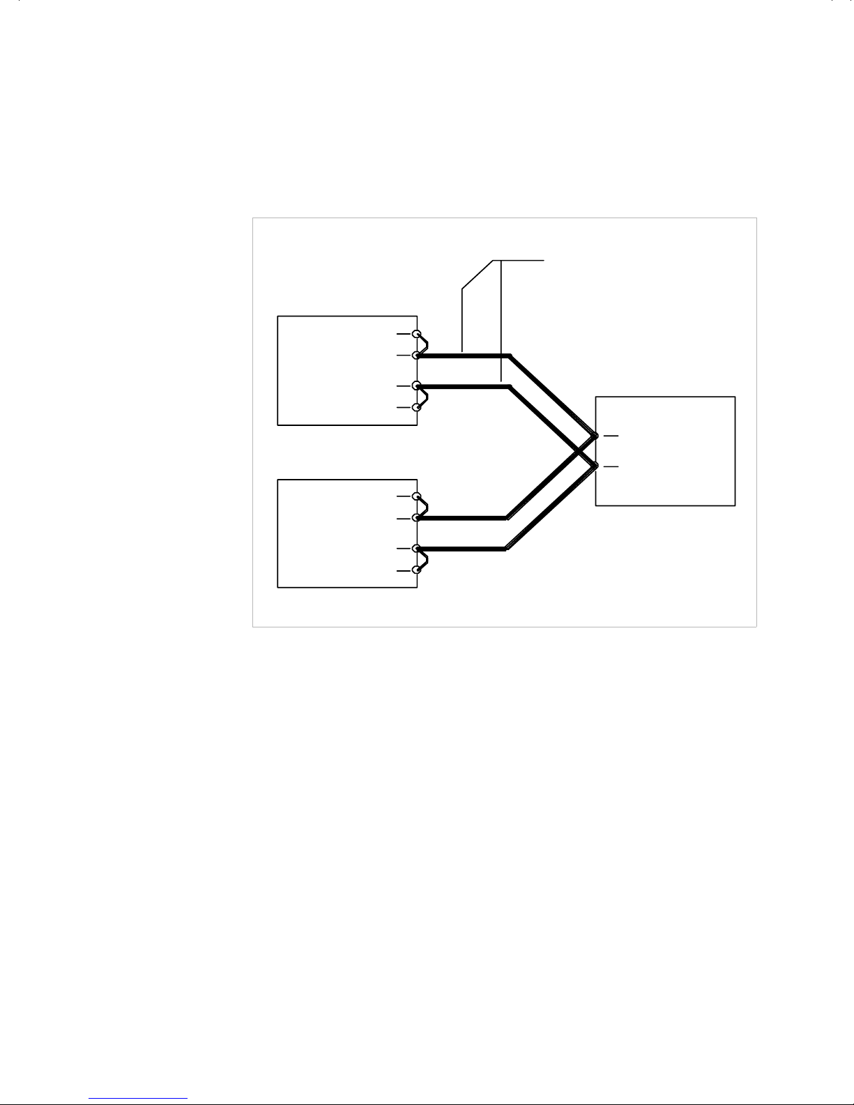
Operation
Using Multiple Supplies
Sensing for Parallel Operation Use default local sensing to enhance power
sharing between units, as the impedance of the load lines will tend to correct for
current imbalance. If you use remote sensing at the load for better voltage regulation,
one supply always operates in current limit mode and supplies most of the power.
LOAD LINES
USE THE LARGEST GAUGE
AND SHORTEST LENGTH
POSSIBLE
POSITIVE SENSE
POSITIVE OUTPUT
TERMINAL
OUTPUT RETURN
TERMINAL
RETURN SENSE
POWER SUPPLY 1
POSITIVE SENSE
POSITIVE OUTPUT
TERMINAL
OUTPUT RETURN
TERMINAL
RETURN SENSE
POWER SUPPLY 2
Figure 3.24Parallel Operation of Multiple Supplies
(Local sense lines shown are default J3 connections.)
POSITIVE LOAD
TERMINAL
NEGATIVE LOAD
TERMINAL
LOAD
Revision A 75

Operation
!
Using Multiple Supplies
Configuring
Multiple
Supplies for
Split Supply
Operation
Split supply operation uses two power supplies to obtain two positive voltages with
a common ground, or to obtain a positive-negative supply.
To obtain two positive voltages, connect the negative output terminals of both
supplies together. The positive output terminals will provide the required voltages
with respect to the common connection. See Figure 3.25. To obtain a
positive-negative supply, connect the negative output terminal of one supply to the
positive output terminal of the second supply. The positive output terminal of the
first supply then provides a positive voltage relative to the common connection while
the negative output terminal of the second supply provides a negative voltage. The
current limits can be set independently. The maximum current available in split
supply operation is equal to the model-rated output of the supplies used. See
Figure 3.26.
CAUTION
To prevent possible damage to the supply, do not connect the remote program return
line of the negative supply to the common connection.
LOAD LINES
USE THE LARGEST GAUGE
AND SHORTEST LENGTH
POSSIBLE
POSITIVE SENSE
POSITIVE OUTPUT
TERMINAL
OUTPUT RETURN
TERMINAL
RETURN SENSE
POWER SUPPLY 1
POSITIVE SENSE
POSITIVE OUTPUT
TERMINAL
OUTPUT RETURN
TERMINAL
RETURN SENSE
POWER SUPPLY 2
Figure 3.25Split Supply Operation of Multiple Supplies
(Two Positive Voltages)
(Local sense lines shown are default J3 connections)
POSITIVE LOAD
TERMINAL #1
POSITIVE LOAD
TERMINAL #2
NEGATIVE LOAD
TERMINAL
LOAD
76 Operating Manual for XKW 3kW Series Power Supply
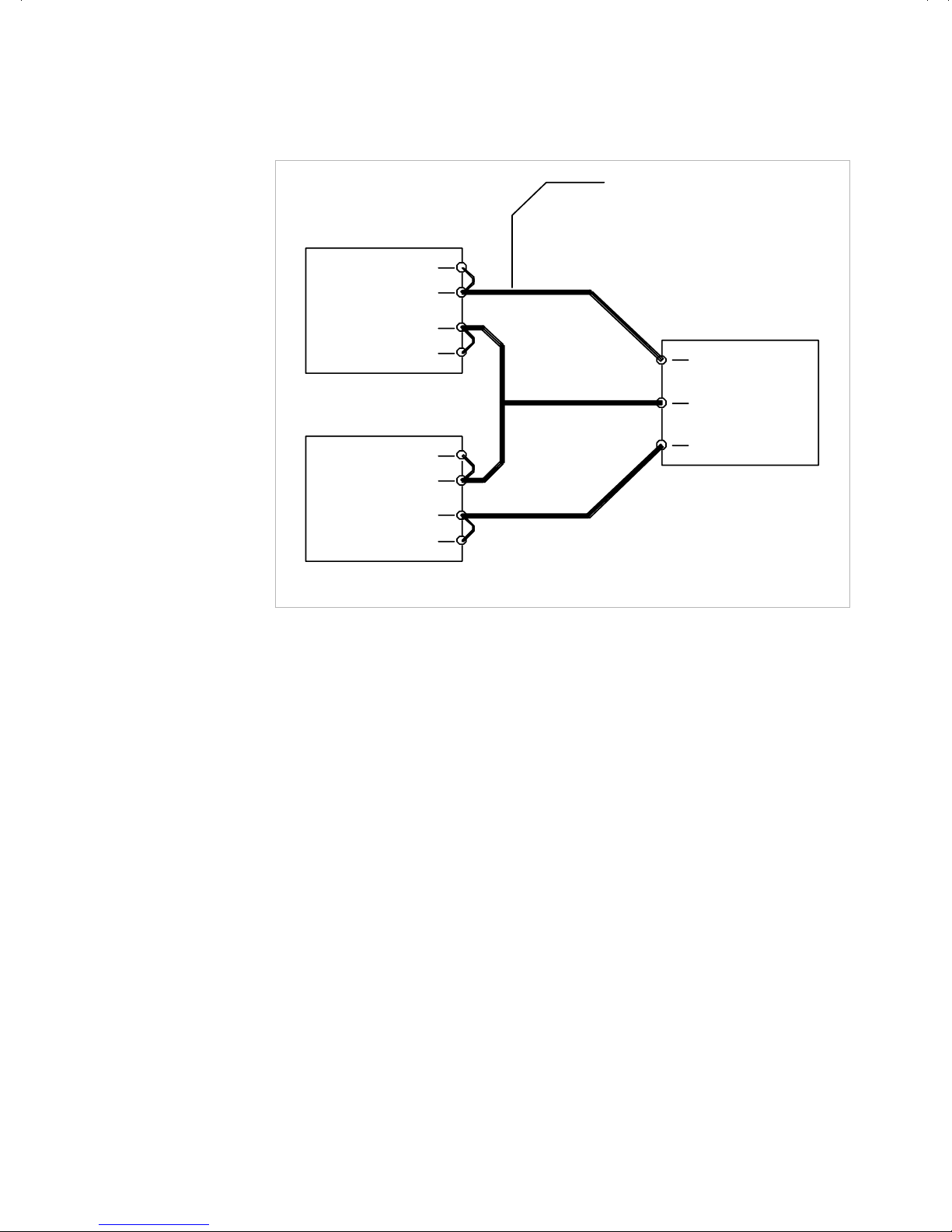
POSITIVE SENSE
POSITIVE OUTPUT
TERMINAL
OUTPUT RETURN
TERMINAL
RETURN SENSE
POWER SUPPLY 1
POSITIVE SENSE
POSITIVE OUTPUT
TERMINAL
OUTPUT RETURN
TERMINAL
RETURN SENSE
LOAD LINES
USE THE LARGEST GAUGE
AND SHORTEST LENGTH
POSSIBLE
POSITIVE LOAD
TERMINAL
COMMON LOAD
TERMINAL
NEGATIVE LOAD
TERMINAL
Operation
Using Multiple Supplies
LOAD
POWER SUPPLY 2
Figure 3.26Split Supply Operation of Multiple Supplies
(Positive-negative Supply)
(Local sense lines shown are default J3 connections.)
Revision A 77

Operation
Using Multiple Supplies
78 Operating Manual for XKW 3kW Series Power Supply

Section 4. Calibration
Introduction
WARNING
Exercise caution when using and calibrating a power supply. High energy levels
can be stored at the output voltage terminals on a power supply in normal
operation. In addition, potentially lethal voltages exist in the power circuit and on
the output and sense connectors of a power supply with a rated output greater
than 40 V. Filter capacitors store potentially dangerous energy for some time
after power is removed.
Adjustments to programming and readback accuracy for the power supply are made
using cover-off procedures which must be performed by a service technician.
Calibration Setup
Service
Environment
and
Precautions
Accessing
Calibration
Potentiometers
• Follow established antistatic procedures.
• Work at a bench with adequate room and support for the unit under test and for
all equipment required.
• To reduce shock hazard, use only an insulated, straight-blade screwdriver when
calibrating trim potentiometers.
• NEVER calibrate these units alone. Ensure that someone is present who can help
should an accident occur.
WARNING
Disconnect AC power from the unit before removing the cover. Even when the
front panel power switch is in the OFF position, live line voltages are exposed
when the cover is removed. Repairs and adjustments must be made by
experienced service technicians only.
WARNING
Use a non-conducting, straight-blade screwdriver to adjust the trim pots.
Revision A 79

Calibration
!
Calibration Setup
CAUTION
Follow established antistatic procedures. There are static-sensitive parts on the
printed circuit boards.
Removing the Cover
1. Unscrew and remove the eight (8) flathead Philips screws from the top of the
cover: two (2) are located near the front panel, six (6) near the rear panel. Use a
#1 Philips screwdriver.
2. Loosen but do not remove the six (6) Philips screws located three (3) to a side in
the slots along each side of the power supply.
3. Lift cover off and set aside.
Removing the Option Board (when required)
The power supply may have either of two option circuit boards installed over the A2
circuit board where the jumpers and switches are located. The option board must be
removed to allow access to them.
1. Unplug any external mating connector and attached wiring.
2. Use a nutdriver to remove the jack screws which fasten the option board to the
rear panel.
3. Unscrew the mounting screws which fasten the option board down.
4. Unplug any attached cables.
Lift out the option board and set aside.
80 Operating Manual for XKW 3kW Series Power Supply

R93
R95
R60
R66
R55
R56
Calibration
Calibration Setup
R23
R24
Figure 4.1 Calibration Adjustment Locations
Revision A 81

Calibration
Calibrating for Programming Accuracy
Calibrating for Programming Accuracy
The offset and range of the voltage and current programming circuits are calibrated
for default 0-5Vdc programming signals at the factory. Recalibration may be
necessary when you use custom 0-10Vdc programming or when you switch back to
0-5Vdc programming after previously calibrating for 0-10Vdc programming.
Voltage
Programming
Circuit
Calibration
Table 4.1 Voltage Programming Calibration Procedures
Function & designation
of multiturn trim pots
Voltage Program Offset
(R93)
Voltage Program Scale
(R60)
Repeat this procedure until the voltage programming is adjusted to the desired
accuracy.
Step Action
1 Disconnect any load. Connect a DVM rated at better than 0.5%
accuracy to the power supply output.
2 Apply 1% of program voltage. Example: 0.1 for 0-10Vdc or 0.05 for
0-5Vdc programming source
3 Adjust R93 until the DVM reads 1% of the rated output voltage.
Example: 0.4Vdc for 40V Model
1 Disconnect any load. Connect a DVM rated at better than 0.5%
accuracy to the power supply output.
2 Apply 100% of program voltage. Example: 10V for 0-10Vdc or 5V for
0-5Vdc programming source
3 Adjust R60 until the DVM reads 100% of the rated output voltage.
Example: 40Vdc for 40V Model
82 Operating Manual for XKW 3kW Series Power Supply

Current
Programming
Circuit
Calibration
Table 4.2 Current Programming Calibration Procedures
Calibration
Calibrating for Programming Accuracy
Function & designation
of multiturn trim pots
Current Program Offset
(R95)
Current Program Scale
(R66)
Repeat this procedure until the current programming is adjusted to the desired
accuracy.
Notes:
1. The DC shunt-DVM combination must be rated better than 0.5% accuracy. The
Step Action
1 Connect a shunt and DVM to the power supply output. See Note 1.
2 Apply 1% of program voltage. Example: 0.1 for 0-10Vdc or 0.05 for
0-5Vdc programming source
3 Adjust R95 until the DVM indicates 1% of the rated output current.
Example: 0.75A for 40V Model. See Note 2.
1 Connect a shunt and DVM to the power supply output. See Note 1.
2 Apply 100% of program voltage. Example: 10V for 0-10Vdc or
5V for 0-5Vdc programming source
3 Adjust R66 until the DVM indicates 100% of the rated output current.
Example: 75A for 40V Model. See Note 2.
recommended current ratings for the DC shunt and connecting wire must be at
least 10% greater than the power supply's output current rating.
2. The required DVM reading is calculated using V=I x R where V is the DVM
reading, I is the current, and R is the DC shunt resistance.
Revision A 83

Calibration
Calibrating for Programming Accuracy
Voltage
Readback
Calibration
The factory calibrates the offset and range of the output voltage and current monitor
circuits to within 1% for the default 0-5Vdc scales. Should you need to recalibrate,
make adjustments to multiturn potentiometers on the A2 Assembly PCB which you
access by removing the cover of the power supply.
Table 4.3 Voltage Readback Calibration
Function & Designation
of multiturn trim pots
Output Voltage Monitor
Offset (R55) 2 Set the power supply output to 1% of its rated output voltage.
Output Voltage Monitor 1 Set the power supply output to 100% of its rated voltage.
Range (R56) 2 Adjust R56 until the monitor DVM reads 100% of the readback scale.
Step Action
1 Disconnect any load. Connect two DVMs; one to the power supply
output and the second to the voltage monitor terminals on the rear
panel J3 connector [J3-19 (Positive) and J3-6 (Negative)]. See Note.
3 Adjust R55 until the monitor DVM reads 1% of the readback scale.
Example: 0.4Vdc for 40V Model.
Example: 40Vdc for 40V Model.
Repeat this procedure until the monitor signal is adjusted to the desired accuracy.
Note:
1. The recommended accuracy rating for the DVMs is four times better than your
desired readback accuracy.
84 Operating Manual for XKW 3kW Series Power Supply

Current
Readback
Calibration
Table 4.4 Current Readback Calibration
Calibration
Calibrating for Programming Accuracy
Function & Designation
of multiturn trim pots
Output Current Monitor
Offset (R23) 2 Set the supply output current to 1% of its rated output current.
Output Current Monitor 1 Set the supply output current to 100% of its rated value.
Range (R24) 2 Adjust R24 until the monitor DVM indicates 100% of the readback
Step Action
1 Disconnect any load. Connect a shunt and DVM across the power
supply output to read the output current. Connect a second DVM to the
rear panel J3 output current monitor terminals. [J3-7 (Pos.) and J3-12
(Neg.)]. See Note 1.
See Note 2.
3 Adjust R23 until the monitor DVM indicates 1% of the readback scale.
Example: 0.75A for 40V Model.
scale. Example: 75A for 40V Model.
Repeat this procedure until the monitor scale is adjusted to the desired accuracy.
Notes:
1. The recommended accuracy of the DVM and DC shunt-DVM combination is
four times better than your desired readback accuracy. The recommended
current ratings for the DC shunt and connecting wire is at least 10% greater than
the power supply's output current rating.
Calculate the required DVM reading using V=I x R where V is the DVM reading,
I is the current, and R is the DC shunt resistance.
Revision A 85

Calibration
Battery Charging
Battery Charging
When using this power supply to charge a battery, take the following precautions to
prevent damage to the supply and/or the battery in case the overvoltage protection
(OVP) circuit is activated.
1. Select a diode rated to handle the required charging current and voltage. Use the
Peak Charging Current Maximum Voltage Diode Type
following table as a reference.
250-350A 40V Two (2) parallel MBR30045CT
60-249A 40V One (1) MBR30045CT
25-59A 100V One (1) MUR7015
10-24A 300V One (1) MUR3040PT
5-9A 500V One (1) MUR1560
<5A 600V One (1) MUR758
2. Connect the diode in series with either supply output to prevent the battery from
discharging through the internal OVP crowbar transistor. The diode must be
mounted on a suitably-rated heatsink to prevent its case temperature from
exceeding the manufacturer's maximum limits.
86 Operating Manual for XKW 3kW Series Power Supply


Xantrex Technology Inc.
1 800 670 0707 Tel toll free NA
1 360 925 5097 Tel direct
1 800 994 7828 Fax toll free NA
1 360 925 5143 Fax direct
customerservice@xantrex.com
www.xantrex.com
TM-25OP-01XN
Printed in Canada
 Loading...