


Sorensen XFR Series
2.8 kW
DC Power Supply with Zero Voltage “Soft Switching”
• Analog programming
• Zero voltage “soft switching”
• Constant voltage or constant current operation
with automatic crossover and mode indication
• Standby/Remote/Local modes
• Front panel button preview of voltage, current, OVP
• Remote sense, 5 V line loss compensation
• LabVIEW® and LabWindows® drivers
The Sorensen XFR Series provides 2.8 kilowatts
of power for research, product development,
and production test applications such as magnet
control, ATE, process control, electroplating and
burn-in. The XFR Series is ideal for applications
where high power and a wide adjustment of
output voltage or current is required.
The XFR Series is designed for excellent thermal
management so each unit can be conveniently
stacked in rack mounts without leaving ventilation
space between each unit.
The XFR Series features zero voltage “soft
switching” which virtually eliminates switching
transients, resulting in lower noise performance
that is closer to linear levels. Soft switching also
increases efciency, decreases heat generation,
and reduces stress on the switching transistors –
resulting in higher reliability.
7.5–600 V
4–300 A
19
0 208 230
208 230
858.458.0223
sales.ppd@ametek.com
AMETEK
Programmable Power
9250 Brown Deer Road
San Diego, CA 92121-2267
USA
10252013
47
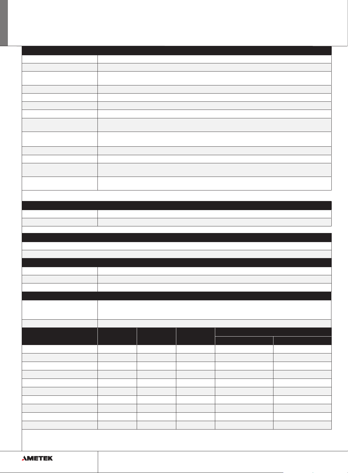
XFR Series : Product Specications
Common
Switching Frequency XFR 2.8 kW: Nominal 31 kHz (62 kHz output ripple) 60 V to 600 V models: nominal 62.5 kHz (125 kHz output ripple).
Time Delay 7 sec maximum from power on until output stable
Voltage Mode Transient Response Time < 3 ms for output voltage to recover within 0.5% of its rated voltage after a step change in load current of up
Maximum Voltage Differential ±600 Vdc from output to safety ground
Remote Start/Stop and Interlock 2.5-15 V signal or TTL-compatible input, selectable logic
Remote Analog Programming Voltage and current programming inputs (source must be isolated): 0-5 k, 0-10 k resistances; 0-5 V, 0-10 V (default) voltage sources
Remote Analog Monitoring Voltage and current monitor outputs 0-5 V, 0-10 V (default) ranges for 0-100% of output
Remote Programming &
Monitoring Accuracy
Maximum Remote Sense
Line Drop Compensation
Front Panel Voltage and Current Control 10-turn voltage and current potentiometers
Front Panel Voltage Control Resolution 0.02% of maximum voltage
Main Output Connector XFR 2.8 kW: 7.5 - 100 V models: nickel-plated copper bus bars with bus bar cover and strain relief; 150V to 600 V models: 4-terminal,
Approvals NRTL approved and CE-marked to UL Std. No. 61010-1, CAN/CSA-C22.2 No. 61010-1-04, EN 610101-1 (Equipment Class I, Pollution
Input
Input Voltage Ranges XFR 2.8 kW: 190-264 Vac, 1φ (24.3 A @ 208 Vac; 20.5 A @ 230 Vac typical), 47-63 Hz; Option: M2 3φ 208 Vac input
AC Input Connector Type 3-terminal, 34 A, 250 V, wire clamp connector with strain relief cover
to 10% to 90% of rated output
1% zero to full scale output for the default range
5 V / line (Line drop is subtracted from total voltage available at supply output.)
wire clamp connector with cover and strain relief
Degree 2, Installation Category II) Meets USA EMC standard: FCC, part 15B, Class A; Meets Canadian EMC standard: ICES-001, Class A.
Protection Features
Over-voltage protection
Over-temperature protection
Environmental
Operating Temperature XFR 2.8 kW: 0 to 50°C
Storage Temperature -20°C to 70°C
Humidity (Non-condensing) Up to 90% RH, non-condensing
Physical XFR 2.8 kW
Dimensions Width: 19” (429.4 mm)
Weight 33 lb (15 kg)
Height: 3.5” (88.9 mm)
Depth: 21” (533.5 mm)
Model Output Voltage Output Current Output Power Line Regulation
Voltage Current
XFR 7.5-300
XFR 12-220
XFR 20-130
XFR 33-85
XFR 40-70
XFR 60-46
XFR 100-28
XFR 150-18
XFR 300-9
XFR 600-4
0-7.5 V 0-300 A 2250 W 2.75 mV 32 mA
0-12 V 0-220 A 2640 W 3.2 mV 24 mA
0-20 V 0-130 A 2600 W 4 mV 15 mA
0-33 V 0-85 A 2805 W 5.3 mV 10.5 mA
0-40 V 0-70 A 2800 W 6 mV 9 mA
0-60 V 0-46 A 2760 W 8 mV 6.6 mA
0-100 V 0-28 A 2800 W 12 mV 4.8 mA
0-150 V 0-18 A 2700 W 17 mV 3.8 mA
0-300 V 0-9 A 2700 W 32 mV 2.9 mA
0-600 V 0-4 A 2400 W 62 mV 2.4 mA
2
48
www.ProgrammablePower.com
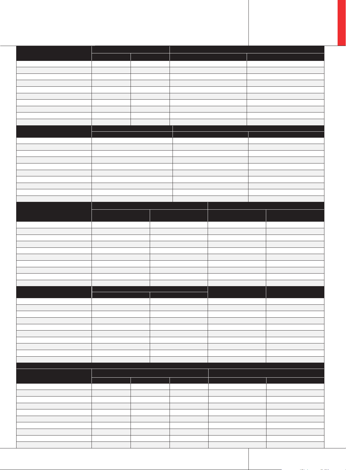
XFR Series : Product Specications
2.8 kW
Model Load Regulation
3
Meter Accuracy
Voltage Current Voltage (1% of Vmax + 1 count) Current (1% of lmax + 1 count)
XFR 7.5-300
XFR 12-220
XFR 20-130
XFR 33-85
XFR 40-70
XFR 60-46
XFR 100-28
XFR 150-18
XFR 300-9
XFR 600-4
6.5 mV 65 mA 0.09 V 4 A
7.4 mV 49 mA 0.13 V 2.3 A
9 mV 31 mA 0.3 V 1.4 A
11.6 mV 22 mA 0.43 V 0.95 A
13 mV 19 mA 0.5 V 0.8 A
17 mV 14.2 mA 0.7 V 0.56 A
27 mV 10.6 mA 1.1 V 0.38 A
35 mV 8.6 mA 1.6 V 0.19 A
65 mV 6.8 mA 4 V 0.1 A
125 mV 5.8 mA 7 V 0.05 A
Model Output Noise (0-20MHz) Output Ripple (rms)
Voltage (p-p) Voltage Current
XFR 7.5-300
XFR 12-220
XFR 20-130
XFR 33-85
XFR 40-70
XFR 60-46
XFR 100-28
XFR 150-18
XFR 300-9
XFR 600-4
100 mV 10 mV 1600 mA
100 mV 10 mV 1200 mA
100 mV 10 mV 400 mA
100 mV 15 mV 300 mA
150 mV 15 mV 200 mA
150 mV 15 mV 100 mA
175 mV 25 mV 80 mA
200 mV 25 mV 40 mA
400 mV 40 mV 20 mA
500 mV 100 mV 10 mA
Model Drift (8 hours)4 Temp Coeffcient
Voltage
(0.05% of Vmax)
XFR 7.5-300
XFR 12-220
XFR 20-130
XFR 33-85
XFR 40-70
XFR 60-46
XFR 100-28
XFR 150-18
XFR 300-9
XFR 600-4
3.75 mV 150 mA 1.5 mV 90 mA
6 mV 110 mA 2.4 mV 66 mA
10 mV 65 mA 4 mV 39 mA
16.5 mA 42.5 mA 6.6 mV 25.5 mA
20 mV 35 mA 8 mV 21 mA
30 mV 23 mA 12 mV 13.8 mA
50 mV 14 mA 20 mV 8.4 mA
75 mV 9 mA 30 mV 5.4 mA
150 mV 4.5 mA 60 mV 2.7 mA
300 mV 2 mA 120 mV 1.2 mA
Model Program Slew Rate
Rise time Fall time
XFR 7.5-300
XFR 12-220
XFR 20-130
XFR 33-85
XFR 40-70
XFR 60-46
XFR 100-28
XFR 150-18
XFR 300-9
XFR 600-4
100 ms 100 ms 0.375-8.25 V 80%
100 ms 100 ms 0.6-13.2 V 82%
100 ms 100 ms 1-22 V 85%
100 ms 100 ms 1.65 - 36.6 V 85%
100 ms 100 ms 2-44 V 87%
100 ms 100 ms 3-66 V 90%
170 ms 170 ms 5-110 V 90%
170 ms 170 ms 7.5-165 V 90%
170 ms 170 ms 15-330 V 91%
170 ms 100 ms 30-660 V 91%
Current
(0.05% of lmax)
6
Voltage
(0.02% of Vmax ºC)
OVP Adjustment Range
(5% to 110% of Vmax)
(0.03% of Vmax ºC)
Interface Specications with RS-232 or GPIB Interface Installed*
Model Program Accuracy Readback Accuracy
Voltage (mV) Current (mA) OVP (mV) Voltage (mV) Current (mA)
XFR 7.5-300
XFR 12-220
XFR 20-130
XFR 33-85
XFR 40-70
XFR 60-46
XFR 100-28
XFR 150-18
XFR 300-9
XFR 600-4
10 +0.12% 900 +0.15% 40 30 +0.12% 900 +0.1%
75 +0.12% 750 +0.15% 75 75 +0.12% 750 +0.1%
75 +0.12% 500 +0.15% 100 75 +0.2% 500 +0.1%
75 +0.3% 425 +0.1% 175 75 +0.3% 425 +0.1%
75 +0.3% 350 +0.15% 200 75 +0.3% 350 +0.1%
150 +0.3% 250 +0.1% 300 150 +0.35% 250 +0.1%
150 +0.35% 140 +0.15% 500 150 +0.35% 140 0.1%
225 +0.35% 120 +0.1% 750 225 +0.35% 120 +0.1%
225 +0.35% 80 +0.1% 1500 225 +0.35% 80 +0.1%
300 +0.35% 80 +0.1% 3000 250 +0.35% 80 +0.1%
5
Current
Efciency
7
858.458.0223
sales.ppd@ametek.com
49

XFR Series : Diagram
16.9 [429.3]
21.2 [538.1]
TOP VIEW
17.5 [443.9]
3.5 [87.6]
50
19.0 [482.6]
FRONT VIEW
XFR 2.8
www.ProgrammablePower.com

XFR 40
Series
Voltage
70
Current
(XXX)
Options
XFR Series
Model Number Description
XFR 2.8 Options and Accessories
MGA / MGB* GPIB / IEEE 488.1
MGP Multi-channel GPIB / IEEE 488.2
MCA CANbus interface for hardware linking multiple units (used with GPIB-M)
MRA / MRB* RS-232 interface
MIA ISOL interface card provides isolated analog control and readback
M2 3-phase 208 Vac input
Specications subject to change without notice.
1. Specications indicate typical performance at 25°C ±5°C, nominal line input of 208 Vac.
2. For input voltage variation over the AC input voltage range, with constant rated load.
3. For 0-100% load variation, with constant nominal line voltage.
4. Maximum drift over 8 hours with constant line, load and temperature, after 30 minute warm-up.
5. Change in output per °C change in ambient temperature, with constant line and load.
6. Measured with stepped 0-10 V analog programming source and a resistive load.
7. Typical efciency at nominal input voltage and rated output power.
8. Apply accuracy specications according to the following voltage program accuracy example:
Set a model 20-130 power supply to 10 V. The expected result will be within the range of 10 V ± 75 mV ± 0.12% of the set voltage of 10 V.
* MGB/MRB 600V output only. MGA/MRA for output less than 600V GB 600V output only. MGA for output less than 600V
2.8 kW
© 2013 AMETEK Programmable Power All rights reserved. AMETEK Programmable Power is the trademark of AMETEK Inc., registered in the U.S. and other countries.
Elgar, Sorensen, California Instruments, and Power Ten are trademarks of AMETEK Inc., registered in the U.S.
sales.ppd@ametek.com
858.458.0223
51

Notes
52
www.ProgrammablePower.com
 Loading...